tm - glynwed · pdf fileindustrial technical manual series vol.vi, ... for specific details...
TRANSCRIPT

Volume VI:DoubleContainmentPiping Systems
Industrial TechnicalManual Series
DOUBLE CONTAINMENT PIPINGSYSTEMS
Encase TM polypropylene p ip ingGuardian PVC and Corzan TM CPVCCustom Guard TM systemsCentra-Guard TM cable- leak detect ion
S E C O N D E D I T I O N

Double Containment Piping Systems
Industrial Technical Manual Series
Vol. VI, 1st Edition
© 2003 by IPEX

About IPEXAt IPEX, we have been manufacturing nonmetallic pipe and fittings for the North American marketplace since 1951. Today,we supply the widest variety of thermoplastic systems available anywhere, including complete lines of pipe, fittings, valvesand custom-fabricated products.
As a leader in the plastic piping industry, IPEX continually develops new products, modernizes manufacturing facilities andacquires innovative process technologies. We formulate our own thermoplastic compounds during development, and maintainstrict quality control during production. Our products are then made available for distribution thanks to a network of regionalstocking locations throughout North America. In addition, our staff take pride in their work, making available to customerstheir extensive thermoplastic knowledge and field experience.
For specific details about any IPEX product, please contact your local IPEX representative or our customer service department(you’ll find contact information on the back cover).
CONTENTS
Section One: Introduction to Double Containment
Overview . . . . . . . . . . . . . . . . . . . . . . . . . . . . . . . . . . . . . . . . . . . . . . . . .5
Section Two: EncaseTM
Overview . . . . . . . . . . . . . . . . . . . . . . . . . . . . . . . . . . . . . . . . . . . . . . . . .7
Dimensions . . . . . . . . . . . . . . . . . . . . . . . . . . . . . . . . . . . . . . . . . . . . . . .8
Section Three: EncaseTM Procedures
Installation . . . . . . . . . . . . . . . . . . . . . . . . . . . . . . . . . . . . . . . . . . . . . .15
Multiple Joint Fusion . . . . . . . . . . . . . . . . . . . . . . . . . . . . . . . . . . . . . . .17
Pipe Modifications . . . . . . . . . . . . . . . . . . . . . . . . . . . . . . . . . . . . . . . . .20
Pipe Clean Out . . . . . . . . . . . . . . . . . . . . . . . . . . . . . . . . . . . . . . . . . . .21
Pipe Termination Fittings . . . . . . . . . . . . . . . . . . . . . . . . . . . . . . . . . . . . .22
Pipe Repair . . . . . . . . . . . . . . . . . . . . . . . . . . . . . . . . . . . . . . . . . . . . . .22
Testing . . . . . . . . . . . . . . . . . . . . . . . . . . . . . . . . . . . . . . . . . . . . . . . . .25
Section Four: Guardian
Overview . . . . . . . . . . . . . . . . . . . . . . . . . . . . . . . . . . . . . . . . . . . . . . . .27
Dimensions . . . . . . . . . . . . . . . . . . . . . . . . . . . . . . . . . . . . . . . . . . . . . .28
Section Five: Guardian Procedures
Installation . . . . . . . . . . . . . . . . . . . . . . . . . . . . . . . . . . . . . . . . . . . . . .37
Termination Fittings . . . . . . . . . . . . . . . . . . . . . . . . . . . . . . . . . . . . . . . .40
Closure Couplings . . . . . . . . . . . . . . . . . . . . . . . . . . . . . . . . . . . . . . . . . .41
Section Six: CustomGuardTM
Overview . . . . . . . . . . . . . . . . . . . . . . . . . . . . . . . . . . . . . . . . . . . . . . . .45
Dimensions . . . . . . . . . . . . . . . . . . . . . . . . . . . . . . . . . . . . . . . . . . . . . .46
Section Seven: CustomGuardTM Procedures
Installation . . . . . . . . . . . . . . . . . . . . . . . . . . . . . . . . . . . . . . . . . . . . . .55
Section Eight: System Design
Guidelines . . . . . . . . . . . . . . . . . . . . . . . . . . . . . . . . . . . . . . . . . . . . . . .61
External Support . . . . . . . . . . . . . . . . . . . . . . . . . . . . . . . . . . . . . . . . . .62
Expansion Loops and Elbows . . . . . . . . . . . . . . . . . . . . . . . . . . . . . . . . . .63
Buried Pipe . . . . . . . . . . . . . . . . . . . . . . . . . . . . . . . . . . . . . . . . . . . . . .65
i

Section Nine: Leak Detection
Centra-GuardTM . . . . . . . . . . . . . . . . . . . . . . . . . . . . . . . . . . . . . . . . . . . .67
Cable Leak Detection . . . . . . . . . . . . . . . . . . . . . . . . . . . . . . . . . . . . . . .74
Section Ten: Specialty Components
Neutratank® . . . . . . . . . . . . . . . . . . . . . . . . . . . . . . . . . . . . . . . . . . . . . .77
EncaseTM . . . . . . . . . . . . . . . . . . . . . . . . . . . . . . . . . . . . . . . . . . . . . . . .78
Guardian/CustomGuardTM . . . . . . . . . . . . . . . . . . . . . . . . . . . . . . . . . . . . .79
Section Eleven: Specifications
EncaseTM . . . . . . . . . . . . . . . . . . . . . . . . . . . . . . . . . . . . . . . . . . . . . . . .81
Guardian . . . . . . . . . . . . . . . . . . . . . . . . . . . . . . . . . . . . . . . . . . . . . . . .82
CustomGuardTM . . . . . . . . . . . . . . . . . . . . . . . . . . . . . . . . . . . . . . . . . . . .86
Appendix A: Conversion Charts . . . . . . . . . . . . . . . . . . . . . . . . . . . . . . . . . . . . . . . . . .91
Appendix B: Checklists . . . . . . . . . . . . . . . . . . . . . . . . . . . . . . . . . . . . . . . . . . . . . . .97
ii

5
OVERVIEW
INTRODUCTIONTO
DOUBLE
CONTAINM
ENT
Safety and environmental issues, such as ground water contamination, have long been serious concerns for North Americanindustry. Add to this the enormous costs of litigation, clean up, and increasingly stringent corporate guidelines and legalregulations, and the importance of fail-safe double containment systems becomes immediately clear.
However, exactly what constitutes ‘double containment’? Although, on paper, simple solutions such as the lining of ditches orsimilar methods may appear to meet double containment requirements, in reality, they fall short. With double containment,engineers are not designing a single system or even two separate single-wall systems, but rather a combination of the two:interrelated systems, where changing conditions continually affect both primary and secondary pipes.
IPEX’s Experience
By investing heavily in people and technology, IPEX has amassed more than 15 years of expertise in design and fabrication ofdouble containment systems. In addition, IPEX is the only manufacturer of double containment systems offering all of thefollowing:
• A specialized and dedicated division dealing exclusively with double containment.
• The ability to manufacture a large majority of double containment components in-house.
• A variety of materials including thermoplastics, thermosets, and metallic and dissimilar systems.
• Both drainage and pressure systems.
• A patented system with 60% fewer joints than conventional systems.
• Both off-the-shelf and custom-designed systems.
• Cable as well as point-of-collection leak detection systems.
Double Containment Systems
With such breadth and depth of products, IPEX offers customers proven designs that best suit their needs. Because of thelarge variety of systems available, it would be difficult to include all of them in one publication. Therefore this manual dealsspecifically with those systems most commonly used, including:
• EncaseTM, a polypropylene piping system that uses proven Enfusion joining methods to provide an easy-to-install, safe, reliable and cost-effective method to convey chemical waste under gravity-flow conditions.
• Guardian systems. Made from PVC and Corzan® CPVC, these systems offer a complete selection of pre-tested modular components that are considered unmatched in the industry. Installed using its patented Centra-Lok™ design, Guardian reduces the number of joints in a system by as much as 60%.
• CustomGuardTM systems. Together with Encase and Guardian, CustomGuard sets IPEX apart from any other double containment system. CustomGuard is available in several different materials including carbon and stainless steel, copper, fiberglass, plastics and dissimilar materials. Unlike other manufacturers, IPEX is not constrained by a limited material selection. This variety enables IPEX to provide customers with the best solution for their double containment needs.
• Centra-GuardTM, a cable leak detection system that offers an economical pro-active solution against potential containment challenges. Its automated, trouble-free and user-friendly design guards against environmental damage and the high cost of clean up.
Please contact your IPEX representative for details on all other systems not included in this manual.

6
This page intentionally
left blank

7
OVERVIEW
EN
CASE
The Encase System has been designed to overcome thedeficiencies of existing double containment systems. Someof the features and benefits of the system are describedbelow.
Polypropylene Material
• Thirty years of success in chemical waste applications.
• High corrosion resistance.
• Wide temperature range.
• Excellent chemical resistance.
Same Material Inside and Out
• Eliminates differential expansion problems.
• Chemical resistance is the same for the entire piping system.
• System integrity is maintained in the event of a primary pipe leak.
Restrained System
• Expansion anchor plates are installed on each fitting to control expansion.
• No expansion loops necessary.
Full Product Range
• 11/2" to 8" primary sizes held in stock.
• Available in both non-flame retardant as well as flame retardant material for above ground installation.
Drainage Pattern Fittings
• Ensures smooth chemical flow.
Proven System
• Enfield piping has been used for chemical waste for over20 years.
Modular Design
• Components are factory fabricated. The only site joining necessary is the fusion of couplings to pipes and fittings.
• Reduces labor costs.
Fast Joining Method
• All site joints are made by electrofusion using an EnfusionTM machine. Joints are completed in minutes, without the need for costly and cumbersome butt fusion machines.
• Quick and simple to make.
• Proven technology.
• Narrower trench widths than for butt fusion, resulting in quicker and cheaper installation.
• Joints can be made in the trench. This reduces installation time.
• Automatic microprocessor-controlled Enfusion unit ensures joint repeatability.
Easy System Testing
• The primary pipe can be inspected and tested prior to closing the secondary joint (impossible with butt-welded systems).
• Any suspect primary joints can be re-fused prior to final closure of the secondary pipe.
Leak Detection Compatible
• Encase is compatible with all common types of leak detection systems.
• Upon request, pipe is furnished with knot-free twine to allow insertion of a pull rope for leak detection cable installation. This minimizes installation time.
Full Product Backup
• Expert personnel are available to assist in every facet of the Encase product.
SECTION TWO: ENCASETM

ENCA
SE
8
DIMENSIONS
Primary/Secondary Part No. L (ft)
11/2 / 4 264150 20
2 / 4 264200 20
3 / 6 266300 20
4 / 8 268400 20
6 / 10 261060 20
8 / 12 261280 20
Pipe- Schedule 40, Socket x Spigot
Primary/Secondary Part No. L
11/2 / 4 314150
2 / 4 314200
3 / 6 316300
4 / 8 318400
6 / 10 311060
8 / 12 311280
Pipe Spool- Schedule 40, Socket x Socket
MADE
TO
ORDER
Secondary Size Part No. L (in.)
4 024000 57/8
6 026000 57/8
8 028000 63/8
10 021000 9
12 021200 10
Secondary Coupling - Socket
Secondary Size Part No. L (in.)
4 014000 85/8
6 016000 105/8
8 018000 111/2
10 011000 111/2
12 011200 111/2
Secondary Repair Coupling - Socket
L
L
L
L

9
EN
CASE
1/4 Bend - Socket x Spigot
A
B
A
B
C
D E
D E
C
1/8 Bend - Socket x Spigot
Equal Wye - Socket x Spigot x Socket
Reducing Wye - Socket x Spigot x Socket
Part No. A (in.) B (in.)
11/2 / 4 044150 123/8 111/4
2 / 4 044200 125/8 11
3 / 6 046300 137/8 111/8
4 / 8 048400 157/8 131/4
6 / 10 041060 203/8 145/8
8 / 12 041280 23 16
Primary/Secondary
Part No. A (in.) B (in.)
11/2 / 4 064150 8 67/8
2 / 4 064200 81/4 65/8
3 / 6 066300 91/8 63/8
4 / 8 068400 101/8 71/2
6 / 10 061060 137/8 8
8 / 12 061280 151/2 83/8
Primary/Secondary
Part No. C (in.) D (in.) E (in.)
11/2 / 4 124150 9 81/8 9
2 / 4 124200 83/4 83/8 83/4
3 / 6 126300 13 91/8 13
4 / 8 128400 161/8 10 ¼ 161/8
6 / 10 121060 183/4 137/8 183/4
8 / 12 121280 211/8 15 ½ 211/8
Primary/Secondary
Primary Secondary Part No. C (in.) D (in.) E (in.)
2 x 11/2 4 x 4 154215 9 83/8 83/4
3 x 11/2 6 x 4 156315 121/2 75/8 111/2
3 x 2 6 x 4 156320 121/4 75/8 111/2
4 x 2 8 x 4 158420 133/4 71/4 131/4
4 x 3 8 x 6 158430 143/8 83/4 143/4
6 x 2 10 x 4 151062 143/4 93/8 141/2
6 x 3 10 x 6 151063 161/8 107/8 157/8
6 x 4 10 x 8 151064 173/4 123/8 171/4
8 x 3 12 x 6 151283 175/8 12 161/8
8 x 4 12 x 8 151284 191/2 125/8 181/4
8 x 6 12 x 10 151286 205/8 141/8 193/4

ENCA
SE
10
Comb. Wye & 1/8 Bend – Socket x Spigot x Socket
Primary Secondary Part No. D (in.) E (in.) F (in.) G (in.)
11/2 4 174150 81/8 9 157/8 121/4
2 4 174200 83/8 83/4 161/8 12
3 6 176300 91/8 13 193/4 17
4 8 178400 101/4 161/8 221/2 20
6 1 171060 137/8 183/4 267/8 221/2
8 12 171280 151/2 191/8 33 5/8 261/2
F
G
ED
Reducing Comb. Wye & 1/8 Bend - Socket x Spigot x Socket
Primary Secondary Part No. D (in.) E (in.) F (in.) G (in.)
2 x 11/2 4 x 4 204215 83/8 83/4 135/8 121/4
3 x 11/2 6 x 4 206315 75/8 111/2 171/8 141/4
3 x 2 6 x 4 206320 75/8 111/2 173/8 14
4 x 2 8 x 4 208420 71/4 131/4 163/4 151/4
4 x 3 8 x 6 208430 83/4 143/4 201/4 177/8
6 x 2 10 x 4 201062 93/8 141/8 177/8 183/4
6 x 3 10 x 6 201063 107/8 157/8 253/8 203/4
6 x 4 10 x 8 201064 123/8 171/4 257/8 21
8 x 3 12 x 6 201283 111/4 17 261/4 213/8
8 x 4 12 x 8 201284 125/8 181/4 273/8 221/4
8 x 6 12 x 10 201286 141/8 163/4 301/4 241/8
F
G
ED
Double Wye - Socket x Spigot
Primary Secondary Part No. D (in.) E (in.) F (in.) G (in.)
11/2 4 224150 9 81/8 9 63/8
2 4 224200 83/4 81/4 83/4 63/16
3 6 226300 14 91/8 13 91/4
4 8 228400 161/8 101/4 161/8 113/8
6 10 221060 183/4 137/8 183/4 131/4
8 12 221280 211/8 151/2 211/8 15
C
G
D E

11
EN
CASE
Reducer Coupling - Socket x Spigot
L
Primary Secondary Part No. L (in.)
2 x 11/2 4 x 4 344215 57/8
3 x 11/2 6 x 4 346315 103/8
3 x 2 6 x 4 346320 113/8
4 x 11/2 8 x 4 348415 115/8
4 x 2 8 x 4 348420 113/4
4 x 3 8 x 6 348430 131/4
6 x 11/2 10 x 4 341061 18
6 x 2 10 x 4 341062 173/4
6 x 3 10 x 6 341063 157/8
6 x 4 10 x 8 341064 141/2
8 x 3 12 x 6 341283 193/4
8 x 4 12 x 8 341284 181/2
8 x 6 12 x 10 341286 151/4
P-Trap - Socket x Spigot
Primary Secondary Part No. A (in.) D (in.) E (in.) H (in.)
11/2 4 374150 133/8 81/4 8 33/8
2 4 374200 131/8 81/4 73/4 33/8
E
D
H A
A
D
J
P-Trap - Socket x Spigot
Primary Secondary Part No. A (in.) D (in.) J (in.)
3 6 376300 313/4 223/4 261/16
4 8 378400 371/2 251/8 293/16
6 10 371060 42 315/8 37
8 12 371280 445/8 371/4 351/8

ENCA
SE
12
K
D
E
Floor Drain - Spigot
Primary Secondary Part No. D (in.) E (in.) K (in.)
11/2 4 514150 111/8 11/2 141/2
2 4 514200 113/8 11/2 141/2
3 6 516300 63/4 11/2 141/2
4 8 518400 7 11/2 141/2
6 10 511060 65/8 11/2 141/2
L
C
Access Tee - Socket x Spigot x Spigot
Primary Secondary Part No. C (in.) L (in.)
11/2 4 544150 11 153/4
2 4 544200 11 151/2
3 6 x 4 540643 12 171/4
4 8 x 4 540844 13 185/8
6 10 x 4 541046 14 217/8
8 12 x 4 541248 15 231/8
Primary Part No. L (in.)
11/2 L241 3
2 L242 31/8
3 L243 41/2
4 L244 43/4
6 L246 67/8
Cleanout - Spigot
L

13
EN
CASE
Primary Part No. L (in.)
11/2 641500 13/4
2 642000 21/4
3 643000 31/8
4 644000 33/8
6 646000 41/2
8 648000 5
10 641000 53/8
12 641200 53/4
End Caps - Socket
L
Flange - Socket, ASA 150
Size Part No. D1 (in.) D2 (in.) E (in.) F (in.) G (in.)
11/2 L361 37/8 5 11/8 9/165/8
2 L362 43/4 6 7/8 11/1611/16
3 L363 6 71/2 11/4 11/167/8
4 L364 71/2 9 13/8 11/16 11/8
6 L366 91/2 107/8 13/8 13/16 1
8 L368 113/4 131/2 11/4 7/8 3/4
10 L3610 141/4 16 11/4 1 3/4
12 L3612 17 19 11/4 1 3/4
d2d1
E
F
G
d2d1
G
F
Blind Flange - ASA 150
Size Part No. d1 (in.) d2 (in.) F (in.) G (in.)
11/2 621500 37/8 5 3/4 3/4
2 622000 43/4 6 3/4 3/4
3 623000 6 71/2 3/4 3/4
4 624000 71/2 9 3/4 3/4
6 626000 91/2 11 7/8 3/4
8 628000 113/4 131/2 7/8 3/4
10 621000 141/4 16 1 3/4
12 621200 17 19 1 3/4

ENCA
SE
14
L
M
End Seal - Socket x Spigot
Primary Secondary Part No. L (in.) M (in.)
11/2 4 644150 8 24
2 4 664200 73/4 24
3 6 666300 81/2 24
4 8 668400 73/4 24
6 10 661060 63/4 24
8 12 661820 63/4 24
L
M
Cleanout Assembly - Socket
Primary Secondary Part No. L (in.) M (in.)
11/2 4 484150 8 12
2 4 484200 73/4 12
3 6 486300 81/2 12
4 8 488400 73/4 12
6 10 481060 63/4 121/2

EN
CASE
PROCEDU
RES
15
INSTALLATION
Pipe and Fittings Assembly
All pipes and fittings have a socket welded into position onthe upstream side of the component, and a spigot on thedownstream side. After fusing the primary joint, a secondarycoupling is used to close the secondary sections together.
EnfusionTM Joints
Encase is easily joined by Enfield’s Enfusion process. Bothprimary and secondary couplings are manufactured with anintegral resistance wire which is precisely molded in placeusing a proprietary molding process. The wire is electricallyheated by a microprocessor controlled Enfusion Control Unit.This results in fusion, bonding the pipe to the fitting. Joiningis achieved within minutes.
The Enfusion joint achieves the optimum level ofperformance where it matters most – at the joint interface.There is a controlled fit, controlled temperature andcontrolled time. All of this is achieved by the EnfusionControl Unit, which ensures proper electrical connections,joint timing and input/output levels. The combination ofthese features provides both simplicity of joining and perfectcontrol. The result is an unparalleled level of jointrepeatability.
The integral resistance wire is manufactured from achrome/nickel alloy, which allows for uniform electricalresistance and heating while offering excellent chemicalresistance.The overall result is a joining method offeringsimplicity and efficiency, while guaranteeing repeatability.
Job site Precautions
1. Do not test the system using compressed air or gases. Only use a hydrostatic test on the system. Testing with air is dangerous.
2. Store pipe and fittings out of direct sunlight. If material is stored outside, it should be covered with a black tarp. If the ambient temperature exceeds 100ºF, make provisions to allow air to circulate beneath the tarp.
3. Handle the Enfusion machine carefully. Do not tamper!Call your IPEX representative for machine service.
4. Do not mix brands. Good joints can only be made using Enfield pipe, fittings and clamps. Mixing brands voids all warranties.
Installation
For installation in cold weather, refer to the ‘Cold WeatherFusion’ procedure described later in this section.
Before making the Enfield joint, it is important to check withan RMS meter, that the power source is providing between104 and 126 volts @ 45 to 65 cycles with 16-amp capacity.The Enfusion machine provides for normal power variations,however generators should be checked to assure the correctoutput is being provided.
1. Using a tube cutter with a wheel designed for plastic (saw and miter box can also be used as an alternative), cut the pipe square making sure to remove all burrs and loose material. Do not chamfer.
2. Using 60-grit emery cloth, prepare the end of the pipe by removing dirt and oil (important to obtain a good bonding) and roughing up an area equal to 1.5 times thefitting’s socket depth. Clean the roughed up area with ethyl or isopropyl alcohol to ensure complete removal of grease and residue. Once treated do not handle this area ofthe pipe or allow it to get dirty.
3. Completely unwind all cables from the Enfusion machine’s frame before use.
4. Insert the pipe all the way to the stop at the bottom of the socket.
Secondary Coupling
Spigot
Socket
SECTION THREE: ENCASETM PROCEDURES

16
ENCA
SE
PROC
EDU
RES
5. Decide whether single or multiple joints are being made.In case of multiple joints consult the “Multiple Joints Fusion” table that follows for cable connections and maximum allowable number of simultaneous joints.
6. Loosely fit IPEX-supplied clamp(s) only over the hub(s) of the socket(s) to be fused. Clamps position must be flush with the outer edge of the socket (Figure 1).
7. Tighten the clamp(s). A tight clamp is essential to the quality of the joint. It should not be possible to rotate the pipe inside the fitting.
8. Turn the Enfusion machine on and observe the copyright message being displayed as the machine runs a self-diagnostic test.
9. Following the “CONNECT OUTPUT LEAD” instruction onthe display, connect the output leads (Figure 2). If required, connect link cable for multiple fusions.
10. Following the “SELECT PIPE SIZE” instructions on the display, select the size of the joint being fused by using the ‘SELECT” button (Figure 3).
This will automatically set the fusion time (Figure 4).
11. Once the correct size is displayed, press the START button. Temperature and welding time will be displayed. Time will count down to zero.
12. Upon completion of the fusion cycle an audible alarm will sound and the message ‘DISCONNECT INPUT LEAD” will be displayed.
13. A 30 second rest period must be observed to allow the joint(s) to cool before disconnecting the leads. The Enfusion machine will automatically reset, ready for the next operation.
14. Allow five additional minutes before removing the clamps so that the joint can sufficiently cool and properly cure (Figure 5).
Figure 1
Figure 3
Figure 2
Figure 4
Figure 5

17
EN
CASE
PROCEDU
RES
Troubleshooting
Problem
Stop the welding process.
Fault with the output current.
Lead disconnected during cycle.
Action
Press the “STOP” button. Use the “SELECT” button to reset.
Press the “SELECT” button to reset.
Reconnect cable and press “START” button. Jointwill be welded for the remaining time. If the jointhas been in a fault condition for more than two minutes, the complete cycle will be run again.
Display
INTERRUPTED WELD - SELECT RESETS.
OUTPUT FAULT - SELECT RESETS.
CONNECTION FAULT - RECONNECT LEAD.
COLD WEATHER FUSION
Whenever possible pipe and fittings should be stored indoors. It is always preferable to perform pipe preparation and weldingin a protected environment. However, should that not be possible, during cold weather (particularly at freezing or below) it isrecommended that both pipe and fittings be stored in similar ambient temperature and conditions.
In addition, when the actual welding takes place in freezing or sub-freezing environments, this cold weather pre-fusionprocedure must be followed.
1 Follow steps 1 through 9 of Standard Enfield Electrofusion Installation.
2 When the “SELECT PIPE SIZE” prompt appears on the screen keep pushing the select button until all pipe sizes have been displayed.
3 Next will appear the first flash cycle: 11/2" to 2".
4 If the fitting(s) being welded is within this flash range, press START.
5 If the fitting(s) being welded is not included in this flash range, press the SELECT button one more time to display the second flash cycle: 3" through 12".
6 Press START.
7 Upon completion of the flash cycle, the display will show the “DISCONNECT INPUT LEAD” message. Do not disconnect the leads
8 Tighten clamps if necessary (see notes below).
9 Allow the joints to cool for 5 minutes before beginning the fusion cycle.
10 After 5 minutes, continue with steps 10 through 14 of the Standard Enfield Electrofusion Installation procedure.
NOTES
Screen the joints being fused from the wind in very cold conditions to prevent heat loss.
Particular care must be taken to adequately tighten the clamps during extremely cold weather because of increased stiffnessof the materials. One or two additional turns of the tightening screw might be required, above and beyond what is commonlysufficient in fair weather conditions. This is particularly true when welding large diameters.
The additional tightening of the clamps, designed to eliminate any gap between the pipe and the fitting, should be performedtowards the end of the flash cycle. However, care must be taken not to overtighten to avoid distorting or crushing the fittingjoint.
Marking of the pipe (indicating socket depth) is also recommended to assure that the pipe remains fully seated in the socketduring the fusion cycle.

MULTIPLE JOINT FUSION
ENCA
SE
PROC
EDU
RES
In-Field Joining
The Encase system is manufactured in modular form fromfactory-assembled components. Minimal site fabrication isrequired and therefore site installation time is cut to aminimum. The only joining necessary is to fuse the primaryand secondary pipe with Encase couplings. Both primary andsecondary joints can be assembled in the trench, or above-ground local to the trench, depending on the site conditions.The general principles for fusing the primary and secondaryEncase couplings to the Encase pipe is essentially the sameas that described above – with some slight modifications inprocedure. These are detailed in the following section.
Primary Pipe Joining
Prior to commencing joining, ensure the trench has beencorrectly prepared to accept the Encase system. Suggestedtrench and bedding preparation details are shown in SectionEight of this manual under “Buried Pipe”.
1. After preparing the trench, the Encase componentsshould be placed in position with the pipe ends aligned forjoining. Each pipe is labelled to facilitate correct alignment.Make sure there is at least 6” of clearance all around thepipe local to the joints to allow easy access.
2. It is essential that the anchor plate at each end of thepipe is positioned so that the drainage and leak detectioncable port is at the bottom of the pipe.
3. All fittings have four access ports to allow the fittings tobe installed at the desired angle. Both pipe and fittings aresupplied with twine to simplify installation of leak detectioncable after primary joining. Make sure the twine is placed outof the way prior to commencing work.
4. Lay the pipe on sandbags in the trench to facilitatesetting the necessary fall on the pipe run to allow freedrainage as dictated by the local codes. This also allows easyaccess for pipe joining.
The chart indicates the number of joints that can be fused at one time. Remember, multiple fusions can only be done withthe same size fittings. Do not attempt multiple fusions of different size fittings.
Attach the connector leads and link cable leads to fitting terminals as shown in Figure 6. The link cables should be connectedin series. Follow the fusion procedure, as outlined in steps 1-14, to complete the multiple fusion.
Note: Each joint being fused must have an IPEX clamp flush with the outer edge of the socket.
11/2
10
2
8
3
4
4
3
6
2
8
1
10
1
12
1
Pipe Size (inches)
Max # of joints
Maximum Allowable Joints Per Size
ENFUSIONCONTROL
UNIT
CONNECTORCABLE
LINKCABLE
Figure 6
18
Top of Pipe
Secondary Pipe
Primary Pipe
Drainage Port
6"

EN
CASE
PROCEDU
RES
5. Alternatively, the trench bed may be completely coveredwith sand or pea gravel. In this case, the bedding materialmust be removed from underneath the secondary pipe to adepth of 6" and along a length of three feet either side of thejoint centerline, to allow insertion and fusion of thesecondary coupling.
6. Clean off the outside surfaces of both the primary andsecondary pipe sections, making sure that all moisture, mudand grit is removed and that the primary coupling is alsoclean.
7. Slide the secondary coupling over the one section of thepipe to be joined so that it is out of the way and does notinterfere with the primary joining process.
8. Make sure the primary joint is properly aligned beforefusion. We suggest a straight edge be placed across the gap(as shown) to ensure the joint is square before joining.
9. Prepare and fuse the primary pipe in the manneroutlined in the figure below.
Secondary Pipe Joining
10. The ends of all fittings and pipe sections are markedwith a white line to show where the secondary couplingshould be positioned for joining. Make sure that all dirt, oil,water and grease is removed from the area between thepipe/fitting end and the white line, and then lightly abradethe pipe surfaces with a 60-grip emery cloth.
CAUTION: It is essential that the white lines are visible on eitherside of the coupling prior to commencing the joining operation.
Failure to position the secondary coupling centrally betweenthe white lines may result in the fusion wires being incontact with the secondary pipe. If this happens, the wirewill overheat and a poor joint will result.
11. Slide the secondary coupling back over the joining areaand onto the mating pipe/fitting. The coupling MUST becentrally located between the white lines of the matingcomponents before fusing.
12. Place one secondary clamp on the outside edge of eachend of the coupling and tighten. It is usually necessary totighten by hand followed by three or four turns of a handwrench to fully lock the secondary coupling into position. Itis essential that, after tightening the clamp, the fit of thesecondary coupling onto the pipe/fitting is checked. Thecoupling MUST NOT move. It if does, the clamp should betightened further until the coupling is FIRMLY LOCKED ontothe pipe/fitting.
Note: Extremes in ambient temperature may result insecondary clamps bottoming out before full pressure on thecoupling can be achieved. Should this occur, the clamp mustbe replaced. When the coupling is correctly locked in place,the clamps should still have a gap between the clamp jaws.This must be verified prior to joint fusion.
PrepareJoint Area
White Line
Clamp
3 ft.
Straight Edge
19

ENCA
SE
PROC
EDU
RES
13. Connect the blue Enfusion lead to the secondary coupling,select the correct fitting size and complete the Enfusion cycleas described previously in the ‘Joining Procedure’.
14. Leave the joint undisturbed for 10 minutes, after whichtime the secondary clamps can be removed and the systempressure tested according to the procedures detailed under‘Testing’ at the end of this section.
PIPE MODIFICATIONS
Encase is factory-supplied in modular form ready for siteassembly. The only fabrication that may be necessary in thefield is modifying the pipe lengths. This should be done fromthe spigot end only and can be easily accomplished as shownbelow.
1. Mark the desired cutting length on the outside of thesecondary pipe and transpose this mark around the entirecircumference.
2. Cut squarely through both the secondary and primarypipe sections using a sharp carpenter’s saw or band saw.
3. Mark the secondary pipe dimension ‘A’ from the end asshown in the table below and transpose this mark around thesecondary pipe circumference.
4. Cut squarely through the secondary pipe, taking care notto cut into primary pipe, using a sharp carpenter’s saw orlarge diameter pipe cutter.
5. Clean any burrs from the pipe ends.
6. Mark a pencil line on the end of the secondary pipe tolocate the joining positions for the secondary coupling. Thepencil line should be at the following distances from the pipeends:
7. Double-check the gap dimension to make sure the spigotlength is correct before fusing the joint.
A
Size (in) Spigot ‘A’ (in)
11/2 / 4 11/8
2 / 4 13/8
3 / 6 13/4
4 / 8 17/8
6 / 10 25/8
8 / 12 27/8
20
Distancefrom end
Size (in) Dist. From End
11/2 / 4 23/8
2 / 4 13/8
3 / 6 29/16
4 / 8 25/8
6 / 10 33/4
8 / 12 41/4
Gap
Size (in) Gap (in)
11/2 /4 11/8
2 / 4 11/4
3 / 6 3/4
4 / 8 11/8
6 / 10 11/2
8 / 12 11/2

21
EN
CASE
PROCEDU
RES
PIPE CLEAN OUT
Encase can be assembled a number of different ways inorder to clean out the system. The individual pipe lengthsand fittings can be assembled on-site from standardcomponents to give the following configurations:
1. The secondary pipe vented and drained.
2. The secondary pipe completely sealed with no provisionfor draining or venting.
1. Secondary Pipe Vented and Drained
Spigot ended cleanout plugs, part number L24, can be usedin sizes up to 6". The clean out can be used as follows.
Pipe Assembly
All pipe is installed so that the downstream end is a primaryspigot connection.
By fusing a pipe spool, part number Series 31, to the end ofthe system, the secondary pipe can be vented to atmosphere,as shown in the diagrams below.
First a pipe spool is fused to the downstream end of the piperun. A cleanout plug, part number series L24, is then fusedinto the socket of the pipe spool.
The assembly is completed by fusing a secondary couplingattached to a short section of secondary pipe, flange andblind flange, as shown in the diagram.
2. Secondary Pipe Sealed
Pipe Assembly
Instead of using a pipe spool, a clean out spool is fused tothe downstream end of the pipe run. It has a built-in cleanout, plus a blind anchor on the downstream side of the spool.This allows for clean out of the primary pipe, while closingoff the space between the primary and secondary pipesections.
Fitting Assembly
Simply order the required number of fittings with a blindanchor plate at the clean out end. IPEX will supply the cleanouts and blind fittings for site assembly.
Liquid Flow
Spigot End
Upstream Downstream
Spigot end of Pipe
Pipe Spool
Cleanout
Secondary Coupling
Flange /Blind Flange
Pipe Spool Cleanout
Blind Anchor Plate
Spigot end of pipe Pipe Spool Cleanout
Specify BlindAnchor Plate
22
ENCA
SE
PROC
EDU
RES
PIPE TERMINATION FITTINGS
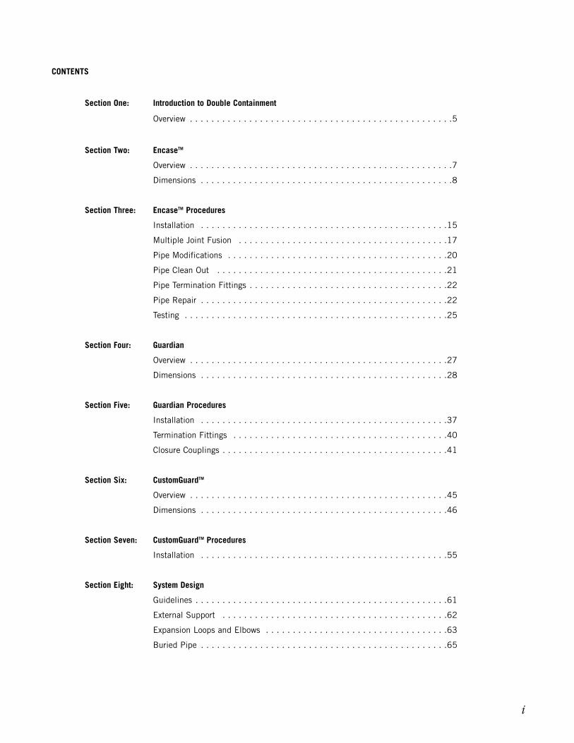
Pipes and fittings can be terminated with clean outs asdescribed above, or by using “end seals”, “end caps” orflanges/blind flanges.
End Seals
End seals are used where the secondary pipe section is beingterminated, but the primary pipe is continued. The end seal,part number series 66, shown below, is used for this purpose.The downstream anchor plate is blind.
End Caps and Flanges/Blind Flanges
End caps and flanges are socket-ended and can be fused toeither the primary or secondary pipe runs to give a morepermanent termination than a clean out.
Pipe Repair
In the unlikely event of a leak from the primary pipe, Encasecan be easily repaired. Encase secondary piping is designedwith the same chemical resistance and integrity as theprimary pipe. This means that the Encase system cancontinue to be used even after a leak has been detected. Thisenables the end-user to make the necessary repairs during ascheduled shutdown rather than having to instantly shut theplant down, with the consequential loss of production.
Procedure
The leak detection system will activate an alarm and indicatethe location of the leak (generally to within +/- one foot ofthe leak source for cable leak detection). Having been alertedto the presence of a leak, the plant operator may choose toeither start immediate repairs, or wait for a scheduledmaintenance shutdown. In any event, the plant operatorshould repair the pipe in the following manner:
1. Drain both the primary and secondary piping and thenflush through with water to remove any residual chemicals
2. Open the cable access tees located on either side of theleak area, then carefully disconnect and remove this part ofthe leak detection cable from the system. (Remember toattach a pull rope to the cable prior to removal. This willenable the cable to be reinserted after the pipe repair hasbeen completed.) The cable should be dried and stored in aclean area.
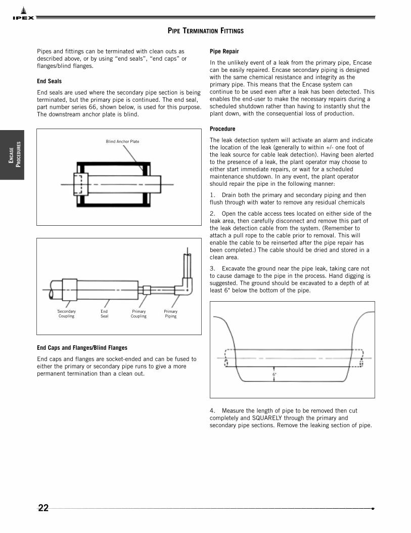
3. Excavate the ground near the pipe leak, taking care notto cause damage to the pipe in the process. Hand digging issuggested. The ground should be excavated to a depth of atleast 6" below the bottom of the pipe.
4. Measure the length of pipe to be removed then cutcompletely and SQUARELY through the primary andsecondary pipe sections. Remove the leaking section of pipe.
Blind Anchor Plate
Secondary Coupling
EndSeal
PrimaryCoupling
Primary Piping
6"

23
EN
CASE
PROCEDU
RES
5. Mark the secondary pipe dimension ‘A’ from the end asshown in the table below and transpose this mark around thesecondary pipe circumference.
6. Cut squarely through the secondary pipe ends, takingcare not to cut into the primary pipe. Clean any burrs frompipe ends.
7. Mark a pencil line on the ends of each primary andsecondary pipe section to locate the joining position for theprimary and secondary repair couplings. The pencil lineshould be at the following distances from the pipe ends.
8. Slide one secondary repair coupling over each end of theexposed secondary pipe sections, and one primary repaircoupling over the exposed spigots of the primary pipesections.
9. Measure, prepare and insert a pipe spool piece into theline to be repaired. For dimensions refer to the table thatfollows.
Note: IPEX will cut and supply short pipe lengths to suit siteconditions. Please contact our Customer ServiceRepresentatives for details.
A
Primary/SecondarySize (in) Gap (in)
11/2 / 4 11/8
2 / 4 13/8
3 / 6 13/4
4 / 8 17/8
6 / 10 25/8
8 / 12 27/8
A
Primary Size Primary Mark Secondary Size Secondary Mark(in) (in) (in) (in)
11/2 3/4 4 21/8
2 1 4 21/8
3 13/8 6 17/8
4 11/2 8 17/8
6 2 10 11/8
8 21/4 12 27/16
Mark forSecondary Coupling
Locator mark forPrimary Coupling
Primary Repair Couplings
Secondary Repair Coupling
Spigot ASpool Piece

24
ENCA
SE
PROC
EDU
RES
10. Prepare the primary and secondary pipe sections forjoining, as described earlier in Section 4. (See ‘Primary PipeJoining’ and ‘Secondary Pipe Joining’).
11. Slide the primary repair couplings back into position toclose the joint. Make sure they are centrally located betweenthe pencil marks previously scribed onto the primary spigotends. Place the hub clamps over the primary repair couplingsand fuse the joints in the normal manner.
12. Remove the hub clamps after allowing the joints to coolfor 10 minutes.
13. Test the primary joints as detailed in the next section.
14. Slide the secondary repair couplings into positionbetween the pencil lines previously scribed onto secondarypipe ends. Place the secondary clamps over the secondaryrepair couplings and fuse the joints as described in‘Secondary Pipe Joining’.
15. Remove the hub clamps after allowing the joints to coolfor 10 minutes.
16. Test the secondary joints as detailed in the next section, then fully drain the system.
17. Surround the pipe with pea gravel, then backfill andconsolidate.
18. Purge the gap between the primary and secondary pipesection with dry nitrogen, or air, making sure the pressuredoes not exceed 5 psi.
19. Replace the leak detection cable and re-seal the accesstees.
20. Close any drain valves.
21. Reset the leak detection alarm module.
Primary Size Secondary Size Spigot ‘A’
11/2 4 11/8
2 4 13/8
3 6 13/4
4 8 17/8
6 10 25/8
8 12 27/8
Center Couplingbetween lines
LeakDetection Cable
25
EN
CASE
PROCEDU
RES
TESTING
The purpose of a site pressure test is to establish that all joints have been correctly made. Encase allows for the individualtesting of the primary and secondary piping.
Primary Pipe
Hydrostatic testing of the primary joint can be performed ten minutes after the final primary joint has been completed. Thepressure testing procedure detailed below should be strictly followed.
1. Fully inspect the installed piping for evidence of mechanical abuse and suspect joints.
2. Split the system into convenient test sections, not exceeding 1,000 ft. The piping should be capped off with an expandable plug at the end of the pipe section to be tested.
3. Prior to starting the test, straight lengths of pipe should be backfilled between fittings that are tested.
4. Slowly fill the pipe section with cold water, taking care to evaluate all trapped air in the process. Use air release valves in any high spots in the system. Do not pressurize at this stage.
5. Leave the pipe for at least one hour to allow an equilibrium temperature to be achieved.
6. Visually check the system for leaks. If clear, check for, and remove any, remaining air from the system.
7. Pressurize the system to a suggested maximum of 10 feet head by means of a standard 10 foot standing watertest using a 10 foot vertical riser, or a low-pressure handpump.
8. Leave the line at 10 feet head for a period of up to eighthours, during which time the water level should not change (standing water test), nor should the pressure gauge reading change (hand pump test).
9. If there is a significant drop in pressure, or extended times are required to achieve the desired pressure, either joint leakage has occurred or air is still entrapped in the line. In this event, inspect for joint leaks. If none are found, check for entrapped air – this must be removed prior to continuing the test.
10. If joints are found to be leaking, the system must be fully drained and the joints repaired. Dry, or marginal, Encase joints can be simply re-fused by following the procedure detailed in this manual. Prior to re-fusing the joint, make sure the hub clamps are in position, then use the flash cycle to drive off any moisture left in the joint. Re-fuse using the correct time for the size of pipe being joined. It should not be necessary to cut out the joint, unless the joint has previously been overheated, contaminated or very badly made in the first instance. Where joints have to be cut out and replaced, the procedures for pipe modification detailed in this manual should be strictly followed.
11. Repeat the 10 feet head test after repairing any leaking joints, following the procedure described above.

26
Secondary Pipe - Hydrostatic Testing
1. After successfully completing the primary pipe 10 foot head test, the secondary pipe can be joined and tested. Do not drain the primary pipe. Simply leave the primary pipe at a 10 foot-head hydrostatic pressure to avoid any possibility of the primary pipe collapsing due to the external load from the secondary pipe test.
2. Fill the secondary pipe with cold water and repeat steps 5 to 11 in ‘Primary Pipe’ procedure..
3. After successfully completing the secondary pipe test, leave the primary pipe full of water and under pressure. Drain the secondary pipe and purge through with low pressure, dry (-100F dewpoint), air or nitrogen to purge out all moisture from the system.
1. For cable leak detection systems, an alternative tohydrostatically testing the secondary pipe exists. Thisalternative testing uses dry, low pressure air, subject to theengineer and/or authority having jurisdiction.
2. Leave the primary pipe at a 10-foot head hydrostaticpressure to avoid any possibility of the primary pipecollapsing due to external load from the secondary pipe test.
3. Fill secondary pipe with air to amaximum of 5 psi for 1 hour using theEncase test cap (see below).
Note: For more information on lowerpressure air testing of thermoplasticpiping systems, reference Unibell B6.
4. While taking great care not toimpact or damage the secondary pipe,the exposed secondary joints should bewiped with a warm soap solution todetect any bubble leaks. In addition,check the pressure gauge to make surethat there is no pressure decay. It isessential that the system is closelymonitored and that the pipe suffers noimpact or other damage during the test.
Note: If the secondary system is tested using air, IPEXrecommends using the Encase test cap. This test cap isdesigned to be used with the system and will provide safe,repeatable test results. It comes complete with air valve,quick disconnect, gage and regulator valve. These test capsare available in all secondary pipe sizes. Contact ourCustomer Service Department to order.
Hose Clamp
Installed Piping
FlexibleCoupling
Quick Connect Test Guage
Test Flangewith Quick Connect
Secondary Pipe - Air Testing
WARNING
Take special care to avoid causing impact to the piping when testing the interstitial space of rigid thermoplastic systems usingcompressed gases. Impact to the system during air testing can cause failure which may result in injury or death.
Conduct this test only when the ambient temperature is 50ºF or above.
The secondary pipe should never be pressurized to any more than 5 psi when using air.
ENCA
SE
PROC
EDU
RES
27
GU
ARDIAN
Material Selection
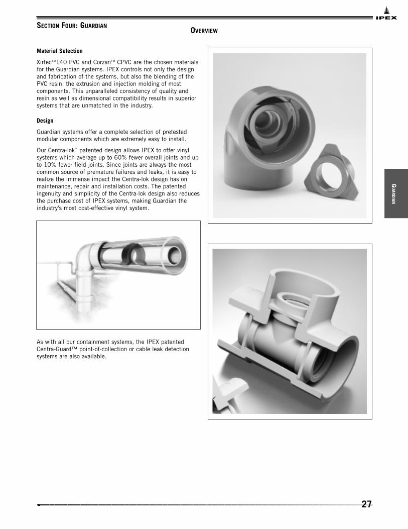
XirtecTM140 PVC and CorzanTM CPVC are the chosen materialsfor the Guardian systems. IPEX controls not only the designand fabrication of the systems, but also the blending of thePVC resin, the extrusion and injection molding of mostcomponents. This unparalleled consistency of quality andresin as well as dimensional compatibility results in superiorsystems that are unmatched in the industry.
Design
Guardian systems offer a complete selection of pretestedmodular components which are extremely easy to install.
Our Centra-lok™ patented design allows IPEX to offer vinylsystems which average up to 60% fewer overall joints and upto 10% fewer field joints. Since joints are always the mostcommon source of premature failures and leaks, it is easy torealize the immense impact the Centra-lok design has onmaintenance, repair and installation costs. The patentedingenuity and simplicity of the Centra-lok design also reducesthe purchase cost of IPEX systems, making Guardian theindustry’s most cost-effective vinyl system.
As with all our containment systems, the IPEX patentedCentra-Guard™ point-of-collection or cable leak detectionsystems are also available.
OVERVIEWSECTION FOUR: GUARDIAN
28
GUAR
DIAN
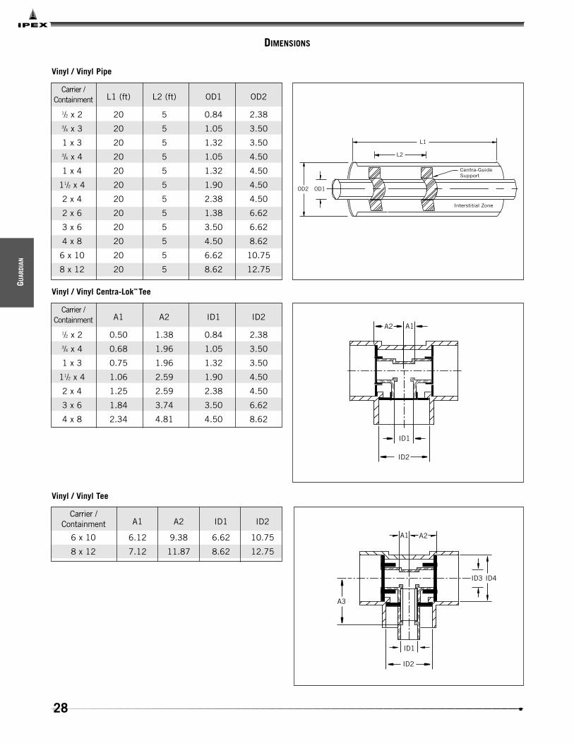
DIMENSIONS
L1
L2
OD2 OD1
Centra-GuideSupport
Interstitial Zone
Vinyl / Vinyl Pipe
L1 (ft) L2 (ft) OD1 OD2
1/2 x 2 20 5 0.84 2.383/4 x 3 20 5 1.05 3.50
1 x 3 20 5 1.32 3.503/4 x 4 20 5 1.05 4.50
1 x 4 20 5 1.32 4.50
11/2 x 4 20 5 1.90 4.50
2 x 4 20 5 2.38 4.50
2 x 6 20 5 1.38 6.62
3 x 6 20 5 3.50 6.62
4 x 8 20 5 4.50 8.62
6 x 10 20 5 6.62 10.75
8 x 12 20 5 8.62 12.75
Carrier /Containment
ID2
ID1
A2 A1
Vinyl / Vinyl Centra-Lok™ Tee
A1 A2 ID1 ID2
1/2 x 2 0.50 1.38 0.84 2.383/4 x 4 0.68 1.96 1.05 3.50
1 x 3 0.75 1.96 1.32 3.50
11/2 x 4 1.06 2.59 1.90 4.50
2 x 4 1.25 2.59 2.38 4.50
3 x 6 1.84 3.74 3.50 6.62
4 x 8 2.34 4.81 4.50 8.62
Carrier /Containment
Vinyl / Vinyl Tee
A1 A2 ID1 ID2
6 x 10 6.12 9.38 6.62 10.75
8 x 12 7.12 11.87 8.62 12.75
ID2
ID1
A3
A2A1
ID3 ID4
Carrier /Containment

29
GU
ARDIAN
ID 1 ID 2
A1
A2
Vinyl / Vinyl Centra-Lok™ 90º Elbow
A1 A2 ID1 ID2
1/2 X 2 0.50 1.38 0.84 2.383/4 X 3 0.68 1.96 1.05 3.50
1 X 3 0.75 1.96 1.32 3.50
11/2 X 4 1.06 2.59 1.90 4.50
2 X 4 1.25 2.59 2.38 4.50
3 X 6 1.84 3.74 3.50 6.62
4 X 8 2.34 4.81 4.50 8.62
6 X 10 3.50 5.93 6.62 10.75
8 X 12 4.56 6.93 8.62 12.75
Carrier /Containment
A1
A2
ID 1
ID2
Vinyl / Vinyl Centra-Lok™ 45º Elbow
A1 A2 ID1 ID2
1/2 x 2 0.25 0.87 0.84 2.383/4 x 3 0.34 1.00 1.05 3.50
1 x 3 0.38 1.00 1.32 3.50
11/2 x 4 0.50 1.25 1.90 4.50
2 x 4 0.62 1.25 2.38 4.50
3 x 6 0.75 2.00 3.50 6.62
4 x 8 1.00 2.25 4.50 8.62
6 x 10 1.75 4.75 6.62 10.75
8 x 12 2.00 6.81 8.62 12.75
Carrier /Containment
L1
L2
OD1OD2
Centra-GuideSupport
Interstitial Zone
PVC DWV / PVC DWV Pipe
L1 (ft) L2 (ft) OD1 OD2
11/2 x 4 20 5 1.90 4.50
2 x 4 20 5 2.38 4.50
3 x 6 20 5 3.50 6.62
4 x 8 20 5 4.50 8.62
6 x 10 20 5 6.62 10.75
8 x 12 20 5 8.62 12.75
Carrier /Containment

30
A1A2
ID1
ID2
PVC DWV / PVC DWV 90º Elbow
A1 A2 ID1 ID2
11/2 x 4 1.75 4.15 1.90 4.50
2 x 4 2.31 4.15 2.38 4.50
3 x 6 3.06 5.87 3.50 6.62
4 x 8 3.88 6.26 4.50 8.62
6 x 10 3.50 5.93 6.62 10.75
8 x 12 4.56 6.93 8.62 12.75
Carrier /Containment
A2A1
A3
ID1
ID2
PVC DWV / PVC DWV Sanitary Tee
A1 A2 A3 A4 A5 A6 ID1 ID2
11/2 x 4 6.13 2.75 3.88 1.75 3.88 4.36 1.90 4.50
2 x 4 6.13 3.68 3.88 2.31 3.88 5.11 2.38 4.50
3 x 6 8.50 4.88 4.94 3.06 4.94 7.13 3.50 6.62
4 x 8 10.88 6.13 5.94 3.88 5.94 8.35 4.50 8.62
6 x 10 3.50 6.00 9.29 - - - 6.62 10.75
8 x 12 4.50 7.14 11.87 - - - 12.22 12.75
Carrier /Containment
A1
A2
ID1 ID2
A5A6
A2
A1
ID1 ID2
A4
A3
G UAR
DIAN

31
GU
ARDIAN
A4
ID1 ID2
A6
A5
A3
A1
A2
PVC DWV / PVC DWV Wye
Carrier / Containment A1 A2 A3 A4 A5 A6 ID1 ID2
11/2 x 4 8.75 5.38 2.13 1.13 4.25 6.38 1.90 4.50
2 x 4 8.75 6.50 2.13 1.38 5.13 6.38 2.38 4.50
3 x 6 10.69 9.63 2.00 1.63 8.00 8.44 3.50 6.62
4 x 8 12.25 11.75 2.63 1.87 9.88 11.75 4.50 8.62
6 x 10 23.50 16.19 7.50 1.75 14.44 19.25 6.62 10.75
8 x 12 28.00 19.75 9.50 2.38 19.75 22.75 8.62 12.75

32
GUAR
DIAN
A1 A2
A3A4
ID1 ID2
A6
A5
PVC DWV / PVC DWV Wye with 1/8 Bend
Carrier / Containment A1 A2 A3 A4 A5 A6 ID1 ID2
11/2 x 4 8.75 5.38 2.13 1.13 9.66 10.72 1.90 4.50
2 x 4 8.75 6.50 2.13 1.38 10.03 10.72 2.38 4.50
3 x 6 10.69 9.63 2.00 1.63 14.34 16.22 3.50 6.62
4 x 8 12.25 11.75 2.63 1.87 17.17 17.74 4.50 8.62
6 x 10 23.50 16.19 7.50 1.75 36.28 38.55 6.62 10.75
8 x 12 28.00 19.75 9.50 2.38 39.71 44.30 8.62 12.75

33
GU
ARDIAN
A5A4
A3
ID1 ID2
A2
A1
PVC DWV / PVC DWV P Trap
Carrier / Containment A1 A2 A3 A4 A5 ID1 ID2
11/2 x 4 13.00 15.30 11.25 1.75 4.14 2.38 4.50
2 x 4 13.55 15.30 11.25 2.31 4.15 3.50 6.62
3 x 6 20.30 23.42 17.25 3.06 5.87 4.50 8.62
4 x 8 23.88 26.55 20.00 3.88 6.25 6.62 10.75
6 x 10 26.98 27.60 21.75 3.50 5.93 8.62 12.75
8 x 12 31.40 32.90 25.40 4.56 6.93 8.62 12.75

34
GUAR
DIAN
ID1
ID2
ID4
ID3
A1
PVC DWV / PVC DWV Reducer / Increaser
A1 ID1 ID2 ID3 ID4
3 x 2 / 6 x 4 4.90 4.50 2.38 6.63 3.50
4 x 2 / 8 x 4 6.50 4.50 2.38 8.63 4.50
4 x 3 / 8 x 6 6.40 6.63 3.50 8.63 4.50
6 x 4 / 10 x 8 7.75 8.63 4.50 10.75 6.63
8 x 6 / 12 x 10 9.25 10.75 6.63 12.75 8.63
Carrier /Containment
A1
ID1
ID2
PVC DWV / PVC DWV Clean Out
Carrier / Containment A1 ID1 ID2
11/2 x 4 7.12 4.50 1.90
2 x 4 7.12 4.50 2.38
3 x 6 11.00 6.63 3.50
4 x 8 12.50 8.63 4.50
6 x 10 18.50 10.75 6.63
A2
A1
ID1
ID2
PVC DWV / PVC DWV Floor Drain
A1 A2 ID1 ID2
3 x 6 11.88 12.00 3.50 6.63
4 x 8 11.88 12.00 4.50 8.63
Carrier /Containment
35
GU
ARDIAN
L1
D1
DoubleO-Ring Seal
ID 1
1/2 FPT Tap OptionalContainment Pipe
Carrier Pipe
OD 1
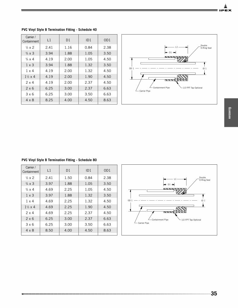
PVC Vinyl Style B Termination Fitting - Schedule 40
L1 D1 ID1 OD1
1/2 x 2 2.41 1.16 0.84 2.383/4 x 3 3.94 1.88 1.05 3.503/4 x 4 4.19 2.00 1.05 4.50
1 x 3 3.94 1.88 1.32 3.50
1 x 4 4.19 2.00 1.32 4.50
11/2 x 4 4.19 2.00 1.90 4.50
2 x 4 4.19 2.00 2.37 4.50
2 x 6 6.25 3.00 2.37 6.63
3 x 6 6.25 3.00 3.50 6.63
4 x 8 8.25 4.00 4.50 8.63
Carrier /Containment
L1
D1
DoubleO-Ring Seal
ID 1
1/2 FPT Tap OptionalContainment Pipe
Carrier Pipe
OD 1
PVC Vinyl Style B Termination Fitting - Schedule 80
L1 D1 ID1 OD1
1/2 x 2 2.41 1.50 0.84 2.383/4 x 3 3.97 1.88 1.05 3.503/4 x 4 4.69 2.25 1.05 4.50
1 x 3 3.97 1.88 1.32 3.50
1 x 4 4.69 2.25 1.32 4.50
11/2 x 4 4.69 2.25 1.90 4.50
2 x 4 4.69 2.25 2.37 4.50
2 x 6 6.25 3.00 2.37 6.63
3 x 6 6.25 3.00 3.50 6.63
4 x 8 8.50 4.00 4.50 8.63
Carrier /Containment

36
This page intentionally
left blank
37
GU
ARDIAN
PROCEDU
RES
INSTALLATION
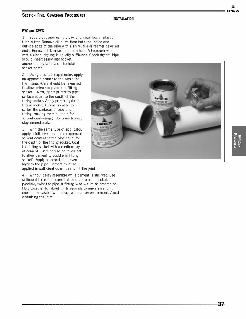
PVC and CPVC
1. Square cut pipe using a saw and miter box or plastictube cutter. Remove all burrs from both the inside andoutside edge of the pipe with a knife, file or reamer bevel allends. Remove dirt, grease and moisture. A thorough wipewith a clean, dry rag is usually sufficient. Check dry fit. Pipeshould insert easily into socket,approximately 1/4 to 3/4 of the totalsocket depth.
2. Using a suitable applicator, applyan approved primer to the socket ofthe fitting. (Care should be taken notto allow primer to puddle in fittingsocket.) Next, apply primer to pipesurface equal to the depth of thefitting socket. Apply primer again tofitting socket. (Primer is used tosoften the surfaces of pipe andfitting, making them suitable forsolvent cementing.) Continue to nextstep immediately.
3. With the same type of applicator,apply a full, even coat of an approvedsolvent cement to the pipe equal tothe depth of the fitting socket. Coatthe fitting socket with a medium layerof cement. (Care should be taken notto allow cement to puddle in fittingsocket). Apply a second, full, evenlayer to the pipe. Cement must beapplied in sufficient quantities to fill the joint.
4. Without delay assemble while cement is still wet. Usesufficient force to ensure that pipe bottoms in socket. Ifpossible, twist the pipe or fitting 1/8 to 1/4 turn as assembled.Hold together for about thirty seconds to make sure jointdoes not separate. With a rag, wipe off excess cement. Avoiddisturbing the joint.
SECTION FIVE: GUARDIAN PROCEDURES
38
GUAR
DIAN
PROC
EDU
RES
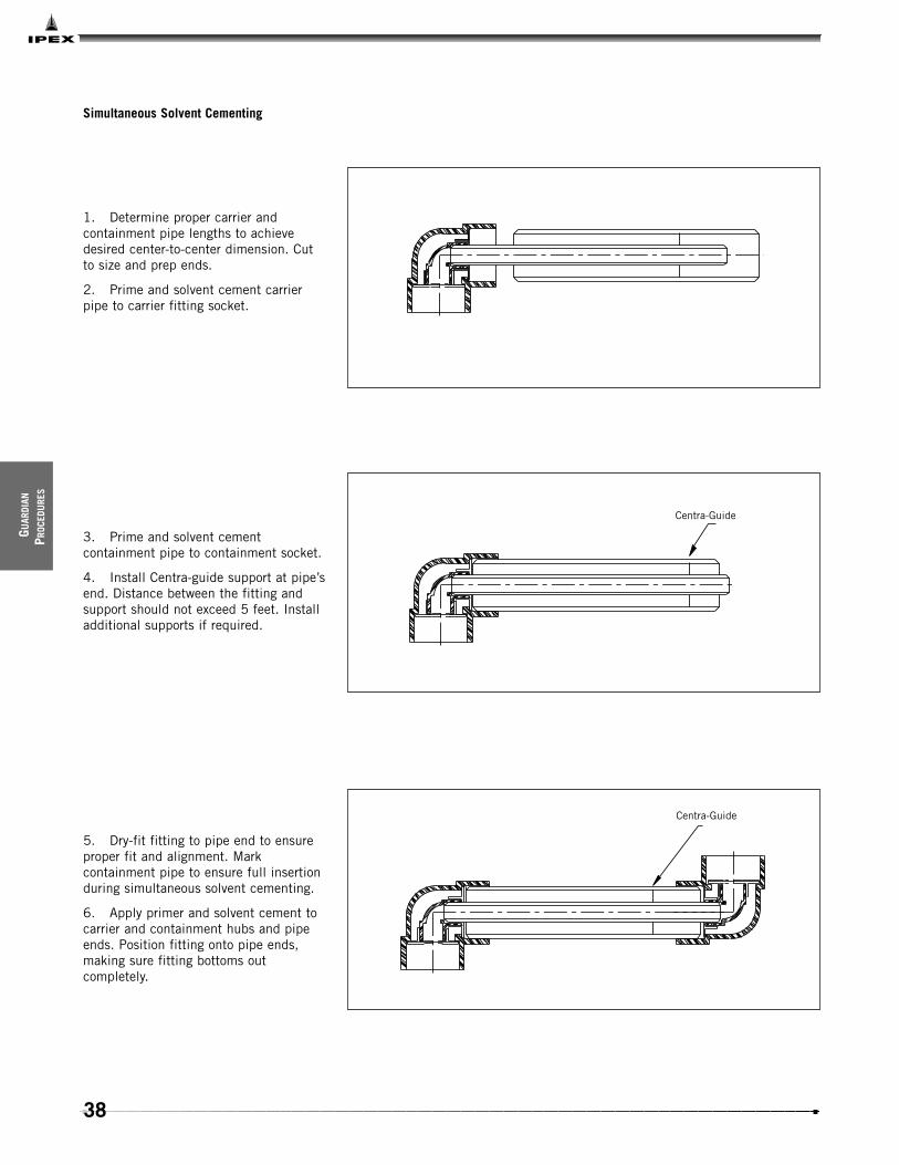
Simultaneous Solvent Cementing
1. Determine proper carrier andcontainment pipe lengths to achievedesired center-to-center dimension. Cutto size and prep ends.
2. Prime and solvent cement carrierpipe to carrier fitting socket.
3. Prime and solvent cementcontainment pipe to containment socket.
4. Install Centra-guide support at pipe’send. Distance between the fitting andsupport should not exceed 5 feet. Installadditional supports if required.
5. Dry-fit fitting to pipe end to ensureproper fit and alignment. Markcontainment pipe to ensure full insertionduring simultaneous solvent cementing.
6. Apply primer and solvent cement tocarrier and containment hubs and pipeends. Position fitting onto pipe ends,making sure fitting bottoms outcompletely.
Centra-Guide
Centra-Guide

39
GU
ARDIAN
PROCEDU
RES
Single Closure Coupling Method
1. Determine proper carrier andcontainment length to achieve desiredcenter-to-center dimension. Cut carrierpipe to size and prep ends. For singleclosure coupling installations, thecontainment pipe is cut into 2 pieces.Piece #1 is equal to 2 x containmentsocket depth. Piece #2 is equal to thepredetermined containment pipe lengthless the overall length of piece #1 plus1". See example.
2. Prime and solvent cement piece #2into fitting. Install support(s) as required.Slide closure coupling onto clean, drycontainment pipe, making sure couplingis installed in proper direction. (Takeappropriate precautions to ensure closurecoupling is kept free of dirt and moistureprior to closure coupling installation. i.e.wrap with plastic or tape ends.) Primeand solvent cement fitting pup intosocket of fitting #2.
3. Prime and solvent cement carrierpipe to fitting #2. If containment pipewas cut properly, there should be a 1"window between containment pipepieces. After successfully testing carrierpipe, install closure coupling perinstructions.
Note: IPEX recommends that vinyl/vinylsystems be installed without closurecouplings whenever possible.
Closure Coupling Centra-Guide
Fitting Pup
Fitting #2
Closure Coupling Centra-Guide
Fitting Pup
Fitting #2Window
1" WindowRemainder
Piece #2Piece #1
Containment Socket
Desired Containment Length
2 X

40
GUAR
DIAN
PROC
EDU
RES
TERMINATION FITTINGS
Style A
Install containment pipe socket flange using standard procedure. Always bevel carrier pipe end or damage to the o-rings willoccur. The blind flange can be ordered with taps to allow for venting, draining, etc.
Style B
PVC and CPVC termination fittings are supplied as one-piece components, complete with carrier pipe o-rings. Always bevelcarrier pipe end or damage to the o-rings will occur. Prime both the containment pipe and socket of termination fitting. Applycement to both containment pipe and termination socket and slide into position, rotating 1/8 to 1/4 turn. Allow 24 hours curetime prior to testing. The fitting can be ordered with taps to allow for venting, draining, etc. Do not apply primer or solventcement to o-rings.
Gasket
150# Blind Flange
Apply StandardO-Ring Lubricant
Bevel Carrier
Bevel Containment Field Joint
150# Socket Flange
Containment
Carrier
Termination Fitting
Apply StandardO-Ring Lubricant
Bevel Carrier Pipe
Bevel Containment
Cement
PVC, CPVC

41
GU
ARDIAN
PROCEDU
RES
CLOSURE COUPLINGS
PVC and CPVC Notes
Guardian vinyl closure coupling installations 3" and uprequires the following:
• gallon containers of primer and cement
• medium-body, slow-set cement
• large daubers/rollers/brushes
IMPORTANT: Always apply primer and cement liberally. Do nottake shortcuts. Follow Guardian’s instructions explicitly.
Note: Always allow 48 hours or more, depending onenvironmental conditions, to cure before testing vinylcarrier/containment pipe.
Factory testing of trial joints made by contractor is availableat no charge. This is strongly recommended.
Common Mistakes
• insufficient amount of cement
• incorrect or outdated cement
• incorrect or no primer used
• pipe ends not bevelled
• pipes misaligned
• contamination (dirt) on cementing area
• improper positioning of closure coupling on containment pipe
• pipe window too large
• movement of pipe sections before cement is fully cured
• wrong size applicator
• closure coupling and/or pipe not dry prior to solvent cementing closure coupling
42
GUAR
DIAN
PROC
EDU
RES
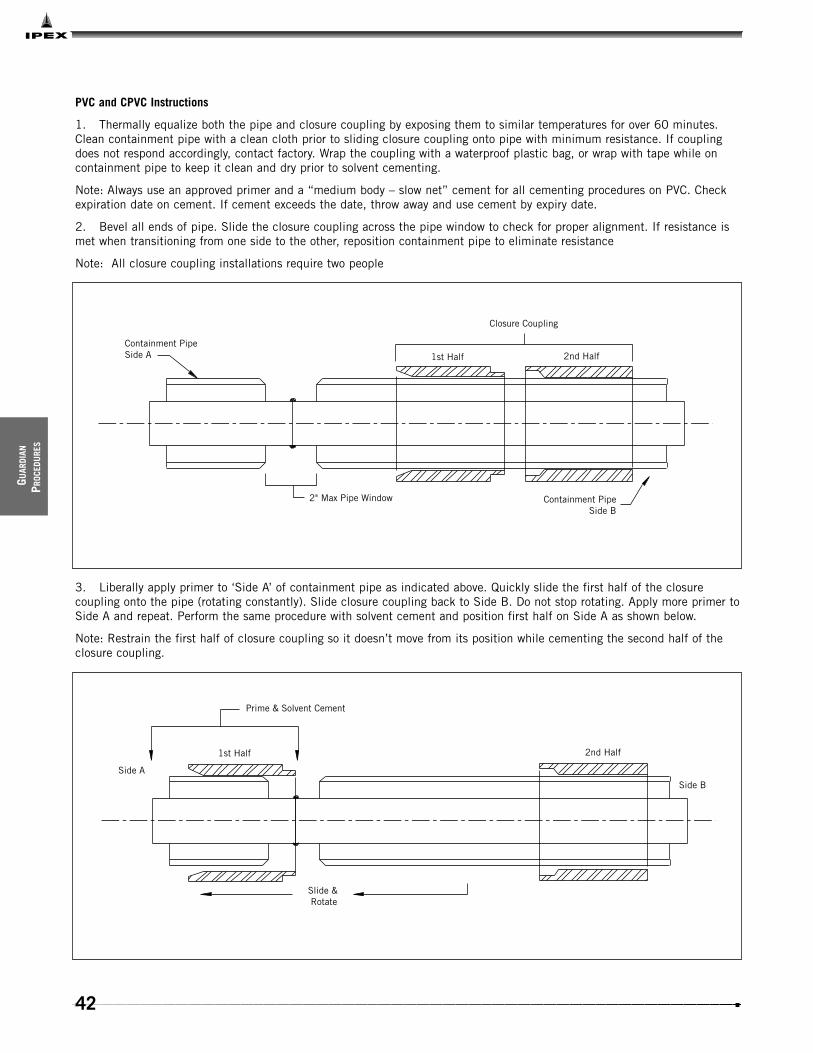
PVC and CPVC Instructions
1. Thermally equalize both the pipe and closure coupling by exposing them to similar temperatures for over 60 minutes.Clean containment pipe with a clean cloth prior to sliding closure coupling onto pipe with minimum resistance. If couplingdoes not respond accordingly, contact factory. Wrap the coupling with a waterproof plastic bag, or wrap with tape while oncontainment pipe to keep it clean and dry prior to solvent cementing.
Note: Always use an approved primer and a “medium body – slow net” cement for all cementing procedures on PVC. Checkexpiration date on cement. If cement exceeds the date, throw away and use cement by expiry date.
2. Bevel all ends of pipe. Slide the closure coupling across the pipe window to check for proper alignment. If resistance ismet when transitioning from one side to the other, reposition containment pipe to eliminate resistance
Note: All closure coupling installations require two people
3. Liberally apply primer to ‘Side A’ of containment pipe as indicated above. Quickly slide the first half of the closurecoupling onto the pipe (rotating constantly). Slide closure coupling back to Side B. Do not stop rotating. Apply more primer toSide A and repeat. Perform the same procedure with solvent cement and position first half on Side A as shown below.
Note: Restrain the first half of closure coupling so it doesn’t move from its position while cementing the second half of theclosure coupling.
Containment PipeSide A
Closure Coupling
1st Half 2nd Half
2" Max Pipe Window Containment Pipe Side B
Prime & Solvent Cement
Side A
1st Half
Slide & Rotate
2nd Half
Side B

43
GU
ARDIAN
PROCEDU
RES
4. Repeat the previous step with the second half of the closure coupling on Side B and place into position as shown below.
5. If the containment pipe will see temperature changes during the curing process or while in operation, shear pins need tobe installed. Using a 3/8" bit, drill holes through the closure coupling and containment pipe as shown above. Use caution whiledrilling to prevent any damage to the carrier pipe. Apply primer and solvent cement to the shear pins (provided with theclosure coupling) and insert into hole. Allow 24 to 48 hours cure time before pressure testing.
Prime & Cement
1st Half 2nd HalfContainment Pipe Side A
2" Max Pipe WindowContainment Pipe Side B
1st Half 2nd HalfContainment Pipe Side A
2" Max Pipe Window
Containment Pipe Side B
Shear Pin (Type 6)

44
GUAR
DIAN
PROC
EDU
RES
2" and 3" Closure Couplings
The procedure for installing 2" and 3" closure couplings is the same as 4" and above, except that the design is slightlydifferent. The 2" and 3" closure couplings have a female socket on the trailing edge of the first half piece and a male end onthe leading edge of the second half. Also, the first half piece is much longer than the second half piece. This means that thetrailing edge of the first half piece will rest on ‘Side B’ of the containment pipe as opposed to being in the 2" window (seedrawing below).
Side A Side B
45
CU
STOMG
UARD
OVERVIEW
Material Selection
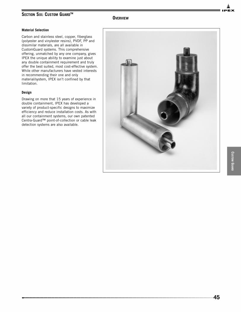
Carbon and stainless steel, copper, fiberglass(polyester and vinylester resins), PVDF, PP anddissimilar materials, are all available inCustomGuard systems. This comprehensiveoffering, unmatched by any one company, givesIPEX the unique ability to examine just aboutany double containment requirement and trulyoffer the best suited, most cost-effective system.While other manufacturers have vested interestsin recommending their one and onlymaterial/system, IPEX isn’t confined by thatlimitation.
Design
Drawing on more that 15 years of experience indouble containment, IPEX has developed avariety of product-specific designs to maximizeefficiency and reduce installation costs. As withall our containment systems, our own patentedCentra-Guard™ point-of-collection or cable leakdetection systems are also available.
SECTION SIX: CUSTOM GUARDTM

46
CUST
OMGU
ARD
DIMENSIONS
L1
L2
OD1OD2
Centra-GuideSupport
Interstitial Zone
Steel / Vinyl - Pipe
L1 (ft) L2 (ft) OD1 OD2
1/2 x 2 20 5 0.84 2.383/4 x 3 20 5 1.05 3.50
1 x 3 20 5 1.32 3.50
11/2 x 4 20 5 1.90 4.50
2 x 4 20 5 2.38 4.50
3 x 6 20 5 3.50 6.62
4 x 8 20 5 4.50 8.62
6 x 10 20 5 6.62 10.75
8 x 12 20 5 8.62 12.75
Carrier /Containment
OD1 OD2
A2
A1
Steel / Vinyl - 90º Elbow
A1 A2 OD1 OD2
1/2 x 2 7.50 6.50 0.84 2.383/4 x 3 8.50 7.50 1.05 3.50
1 x 3 8.50 7.50 1.32 3.50
11/2 x 4 8.50 7.50 1.90 4.50
2 x 4 9.25 8.25 2.38 4.50
3 x 6 10.50 9.50 3.50 6.63
4 x 8 15.00 14.00 4.50 8.63
6 x 10 18.00 17.00 6.63 10.75
8 x 12 21.70 20.70 8.63 12.75
Carrier /Containment
A1A2
OD1
OD2
Steel / Vinyl - 45º Elbow
A1 A2 OD1 OD2
1/2 x 2 8.50 7.50 0.84 2.383/4 x 3 8.50 7.50 1.05 3.50
1 x 3 8.62 7.62 1.32 3.50
11/2 x 4 8.75 7.75 1.90 4.50
2 x 4 9.25 8.25 2.38 4.50
3 x 6 8.75 7.75 3.50 6.63
4 x 8 11.00 10.00 4.50 8.63
6 x 10 15.00 14.00 6.63 10.75
8 x 12 18.94 17.94 8.63 12.75
Carrier /Containment

47
CU
STOMG
UARD
OD1 OD2
A2
A1
Steel / Vinyl - Tee
A1 A2 OD1 OD2
1/2 x 2 5.25 4.25 0.84 2.383/4 x 3 6.60 5.60 1.05 3.50
1 x 3 6.60 5.60 1.32 3.50
11/2 x 4 8.10 7.10 1.90 4.50
2 x 4 8.10 7.10 2.38 4.50
3 x 6 10.50 9.50 3.50 6.63
4 x 8 14.50 13.50 4.50 8.63
6 x 10 17.90 16.90 6.63 10.75
8 x 12 21.70 20.70 8.63 12.75
Carrier /Containment
L1
L2
OD2 OD1
Centra-GuideSupport
Interstitial Zone
Steel / Steel - Pipe
L1 (ft) L2 (ft) OD1 OD2
1/2 x 2 20 5 0.84 2.383/4 x 3 20 5 1.05 3.50
1 x 3 20 5 1.32 3.50
11/2 x 4 20 5 1.90 4.50
2 x 4 20 5 2.38 4.50
3 x 6 20 5 3.50 6.62
4 x 8 20 5 4.50 8.62
6 x 10 20 5 6.62 10.75
8 x 12 20 5 8.62 12.75
Carrier /Containment
OD1 OD2
A2
A1
Steel / Steel - 90º Elbow
A1 A2 OD1 OD2
1/2 x 2 7.50 6.50 0.84 2.383/4 x 3 8.50 7.50 1.05 3.50
1 x 3 8.50 7.50 1.32 3.50
11/2 x 4 8.50 7.50 1.90 4.50
2 x 4 9.25 8.25 2.38 4.50
3 x 6 10.75 9.75 3.50 6.63
4 x 8 15.00 14.00 4.50 8.63
6 x 10 17.62 16.63 6.63 10.75
8 x 12 19.00 18.00 8.63 12.75
Carrier /Containment

48
CUST
OMGU
ARD
A1A2
OD1OD2
Steel / Steel - 45º Elbow
A1 A2 OD1 OD2
1/2 x 2 8.50 7.50 0.84 2.383/4 x 3 8.50 7.50 1.05 3.50
1 x 3 8.62 7.62 1.32 3.50
11/2 x 4 8.75 7.75 1.90 4.50
2 x 4 9.25 8.25 2.32 4.50
3 x 6 8.75 7.75 3.50 6.63
4 x 8 13.00 12.00 4.50 8.63
6 x 10 18.25 17.25 6.63 10.75
8 x 12 19.50 18.50 8.63 12.75
Carrier /Containment
A1
A2
OD1 OD2
Steel / Steel - Tee
A1 A2 (ft) OD1 OD2
1/2 x 2 4.50 3.50 0.84 2.383/4 x 3 7.00 6.00 1.05 3.50
1 x 3 6.70 5.70 1.32 3.50
11/2 x 4 7.75 6.75 1.90 4.50
2 x 4 7.30 6.30 2.37 4.50
3 x 6 9.63 8.63 3.50 6.63
4 x 8 13.13 12.13 4.50 8.63
6 x 10 17.63 16.63 6.63 10.75
8 x 12 19.00 18.00 8.63 12.75
Carrier /Containment
L1
L2
OD2 OD1
Centra-GuideSupport
Interstitial Zone
Steel / FRP - Pipe
L1 (ft) L2 (ft) OD1 OD2
1/2 x 2 20 5 0.84 2.383/4 x 3 20 5 1.05 3.50
1 x 3 20 5 1.32 3.50
11/2 x 4 20 5 1.90 4.50
2 x 4 20 5 2.38 4.50
3 x 6 20 5 3.50 6.62
4 x 8 20 5 4.50 8.62
6 x 10 20 5 6.62 10.75
8 x 12 20 5 8.62 12.75
Carrier /Containment

49
CU
STOMG
UARD
OD1 OD2
A2
A1
Steel / FRP - 90º Elbow
A1 A2 OD1 OD2
1/2 x 2 7.50 6.50 0.84 2.383/4 x 3 8.50 7.50 1.05 3.50
1 x 3 8.50 7.50 1.32 3.50
11/2 x 4 8.50 7.50 1.90 4.50
2 x 4 9.25 8.25 2.38 4.50
3 x 6 11.50 10.50 3.50 6.63
4 x 8 15.00 14.00 4.50 8.63
6 x 10 17.63 16.63 6.63 10.75
8 x 12 19.00 18.00 8.63 12.75
Carrier /Containment
A2A1
OD1
OD2
Steel / FRP - 45º Elbow
A1 A2 OD1 OD2
1/2 x 2 8.50 7.50 0.84 2.383/4 x 3 8.50 7.50 1.05 3.50
1 x 3 8.62 7.62 1.32 3.50
11/2 x 4 8.75 7.75 1.90 4.50
2 x 4 9.25 8.25 2.38 4.50
3 x 6 8.75 7.75 3.50 6.63
4 x 8 13.00 12.00 4.50 8.63
6 x 10 18.25 17.25 6.63 10.75
8 x 12 19.50 18.50 8.63 12.75
Carrier /Containment
OD1 OD2
A2
A1
A1 A2
OD1OD2

50
CUST
OMGU
ARD
C
A
ID OD
A1
B1
B
PVC Closure Coupling - Schedule 40
Carrier / Containment A A1 B B1 C ID OD
2 4.30 1.00 2.40 1.00 6.75 2.37 2.72
3 8.00 2.00 4.00 2.00 10.00 3.50 4.00
4 8.00 2.00 4.70 2.00 11.00 4.50 5.05
6 7.25 2.00 3.50 2.00 9.00 6.63 7.37
8 9.25 2.00 4.50 2.00 12.00 8.63 9.81
10 11.20 2.00 5.20 2.00 14.50 10.75 11.50
12 14.00 2.00 7.00 2.00 19.50 12.75 13.62

51
CU
STOMG
UARD
C
A
ID OD
A1
B1
B
PVC Closure Coupling - Schedule 80
Carrier / Containment A A1 B B1 C ID OD
2 3.25 1.00 3.25 1.00 5.75 2.37 2.89
3 4.00 1.00 4.00 1.00 7.00 3.50 4.17
4 4.75 2.00 4.75 2.00 8.00 4.50 5.23
6 6.50 1.50 3.00 1.50 8.00 6.63 8.00
8 9.25 1.50 4.50 1.50 12.50 8.63 10.12
10 12.00 2.00 6.00 2.00 14.00 10.75 11.87
12 14.00 2.00 7.00 2.00 19.50 12.75 14.12

52
CUST
OMGU
ARD
OD2
OD1
A2A1
Steel / FRP - Tee
A1 A2 OD1 OD2
1/2 x 2 7.00 6.00 0.84 2.383/4 x 3 7.38 6.32 1.05 3.50
1 x 3 7.75 6.75 1.32 3.50
11/2 x 4 9.25 8.25 1.90 4.50
2 x 4 9.00 8.00 2.38 4.50
3 x 6 11.50 10.50 3.50 6.63
4 x 8 13.13 12.13 4.50 8.63
6 x 10 17.63 16.63 6.63 10.75
8 x 12 19.00 18.00 8.63 12.75
Carrier /Containment
ID1
L1
Carbon Steel - Closure Coupling
Containment L1 ID1
2 6.00 2.50
3 6.00 3.62
4 6.00 4.62
6 6.00 6.75
8 6.00 8.75
10 6.00 10.87
12 6.00 12.87
OD2
OD1
A2A1

53
CU
STOMG
UARD
Outer Sections (2)(I.D. Sanded Only)
Inner Sections (2)(I.D. & O.D. Sanded)
Carrier Pipe
Containment Pipe
Worm Clamp (2)
FRP - Closure Coupling
Adhesive Requirement Chart (5 oz. kits)
Pipe Size (in) Adhesive Required
2 1/2
3 1/2
4 1
6 2
8 2
10 3
12 3
Wing LengthNote #1
120º
WingLength
I.D.Note #2
Pipe / Fitting Support, Centra-GuideTM
Size (in) Stock I.D.#2 Wing Length Part #
1/2 0.19 0.83 1.75 728007
3/4 0.19 1.04 1.75 728008
1 0.25 1.30 1.25 728009
11/2 0.25 1.89 1.10 728011
2 0.25 2.36 2.13 728012
3 0.38 3.49 1.50 728014
4 0.38 4.49 1.75 728016
6 0.50 6.61 1.75 728018
8 0.50 8.61 1.75 728019
10 0.75 10.70 2.00 728020
Kit contains:
2 – inner 180 degree FRP shells—I.D & O.D. de-glossed
2 – outer 180 degree FRP shells—I.D. de-glossed
2 – worm clamps
1 – epoxy resin/hardener bonding kit
2 – mixing sticks, gloves, sand paper and a brush
General Notes:
1. Length is sized to fit bore of containment pipe.
2. I.D. sized to provide non-slip against carrier pipe.
Clip is approx. 2" wide.

54
CUST
OMGU
ARD
Carbon Steel Butt Weld Termination
1/2" MPT Optional
Field Weld by others type
ID 1
Carrier Pipe
L1
OD 2
L1 ID1 OD2
1/2 x 2 3.00 0.89 2.38
1 x 3 3.50 1.37 3.50
11/2 x 4 4.00 1.96 4.50
2 x 4 4.00 2.43 4.50
3 x 6 5.50 3.55 6.62
4 x 8 6.00 4.56 8.62
6 x 10 6.00 6.68 10.75
8 x 12 7.00 8.68 12.75
Carrier /Containment

55
INSTALLATION
CU
STOMGU
ARD
PROCEDU
RES
Metal/Vinyl, Metal/FRP
This is an example of a metal carrier and vinyl containment90-degree elbow being joined to its mating pipes. Fitting issupplied with metal pipe beveled for welding and spigotcontainment ends. Metal pipe is welded and, after testing,the closure coupling is installed. The pipe window should notexceed two inches. All joints on this type of system requirethis procedure.
Note: To close FRP window, see FRP closure couplinginstructions.
WARNING: Flammable vapors may be present in the spacebetween the carrier pipe and containment pipe. Use cautionwhen an open flame is present or when welding.
Carrier Pipe Weld(by certified welder only)
Centra-GuideSupports (Type)
See section on vinyl closures for detailsSection on FRP closure couplings for details
Vinyl or FPR Containment
Metal Carrier
Fitting
FieldWeld
Pipe
Typical Socket Weld
SECTION SEVEN: CUSTOM GUARDTM PROCEDURES

56
CUST
OMGU
ARD
PROC
EDU
RES
Metal/Vinyl: Style A Termination Fitting
Install containment pipe socket flange using standardprocedure. The pre-bored blind flange should be installedand back-welded to the carrier pipe. The blind flange can beordered with tape to allow for venting, draining, etc.
WARNING: Flammable vapors may be present in the spacebetween the carrier pipe and containment pipe. Use cautionwhen an open flame is present or when welding.
Always purge the space between the carrier pipe and thecontainment pipe with clean, dry nitrogen and then test witha gas fume meter (sniffer) before welding or subjecting thesystem to an open flame.
Gasket
Field Weld(by a certified welder)
150# Socket Flange
Field Joint
Vinyl Containment
Metal Carrier
57
CU
STOMGU
ARD
PROCEDU
RES
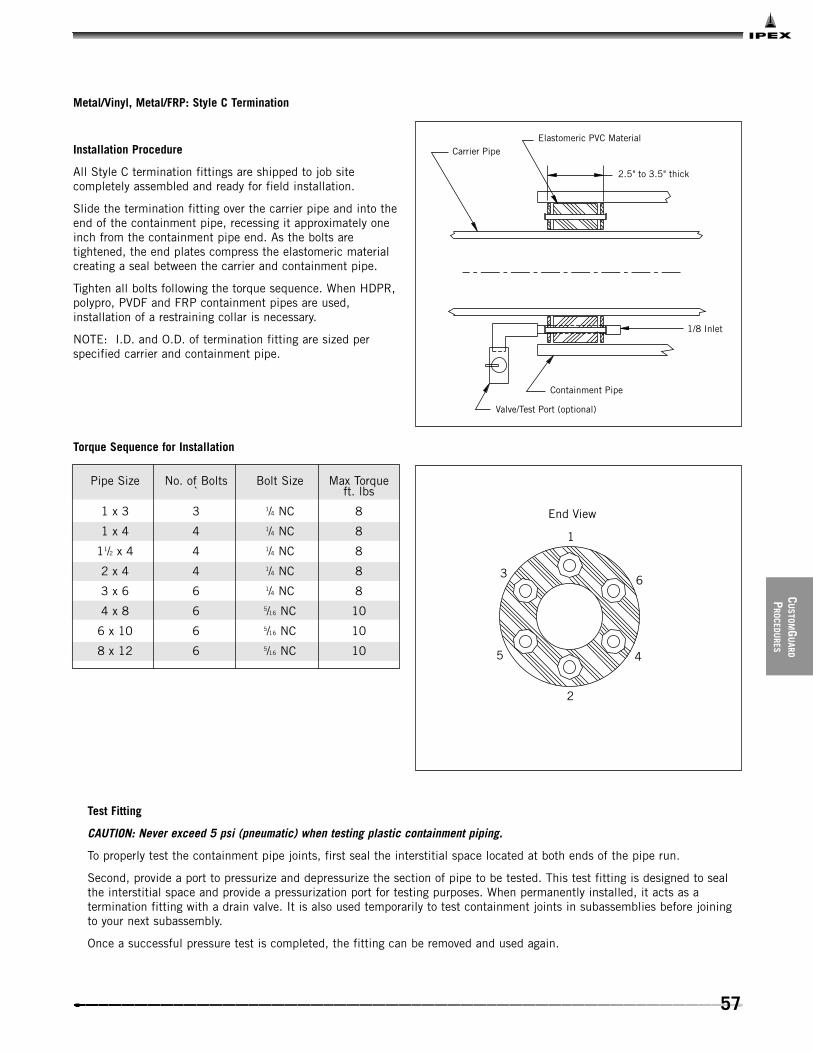
Installation Procedure
All Style C termination fittings are shipped to job sitecompletely assembled and ready for field installation.
Slide the termination fitting over the carrier pipe and into theend of the containment pipe, recessing it approximately oneinch from the containment pipe end. As the bolts aretightened, the end plates compress the elastomeric materialcreating a seal between the carrier and containment pipe.
Tighten all bolts following the torque sequence. When HDPR,polypro, PVDF and FRP containment pipes are used,installation of a restraining collar is necessary.
NOTE: I.D. and O.D. of termination fitting are sized perspecified carrier and containment pipe.
Elastomeric PVC Material
2.5" to 3.5" thick
Carrier Pipe
1/8 Inlet
Containment Pipe
Valve/Test Port (optional)
Metal/Vinyl, Metal/FRP: Style C Termination
Torque Sequence for Installation
1
6
4
2
3
5
End View
Pipe Size No. of Bolts Bolt Size Max Torque` ft. lbs
1 x 3 3 1/4 NC 8
1 x 4 4 1/4 NC 8
11/2 x 4 4 1/4 NC 8
2 x 4 4 1/4 NC 8
3 x 6 6 1/4 NC 8
4 x 8 6 5/16 NC 10
6 x 10 6 5/16 NC 10
8 x 12 6 5/16 NC 10
Test Fitting
CAUTION: Never exceed 5 psi (pneumatic) when testing plastic containment piping.
To properly test the containment pipe joints, first seal the interstitial space located at both ends of the pipe run.
Second, provide a port to pressurize and depressurize the section of pipe to be tested. This test fitting is designed to sealthe interstitial space and provide a pressurization port for testing purposes. When permanently installed, it acts as atermination fitting with a drain valve. It is also used temporarily to test containment joints in subassemblies before joiningto your next subassembly.
Once a successful pressure test is completed, the fitting can be removed and used again.

58
CUST
OMGU
ARD
PROC
EDU
RES
General Notes
Epoxy adhesive may require a heat source to enhance curingin cold weather conditions. Please consult factory. If heatblankets are required, refer to cure times shown on adhesiveinstruction and heating blanket.
Carefully handle FRP parts to avoid contamination. Use newgloves or clean, dry cotton cloths. Protect the bondingsurfaces from any moisture; during wet weather, tenting isrequired.
Installation Instructions
1. Center the inner FRP shells over the containment pipewindow. Mark the pipe at each end of the shells. Using asander with 40-grit belt, sand (de-gloss only) the overlay areaof the containment pipe beyond your marks.
2. Again, place the inner FRP shells over the pipe window.Examine and fit, as necessary, the mating edge of the shellsto provide a 1/8 inch maximum gap between mating edge (oneside only). Remove after proper fit is verified.
3. Using sandpaper, lightly finish sanding all shell bondingsurfaces, then brush any dust from all shell and pipesurfaces to be bonded. Install a loose worm clamp outsideeach pipe mark.
4. Following the mixing instructions furnished with your kit,mix the hardener and resin until a consistent color isachieved. Pot life allows for a 15 to 20 minute workingcycle.
5. Apply a thin, even coat of mixed epoxy to the sandedpipe and inner shells. Place the inner shells over the pipewindow (center), re-coat the complete O.D. of the two innershells including seams as well as the two I.D. surface of theouter shells. Place the coated outer shells over the coatedinner shells ensuring seam overlap occurs.
6. Position the two worm clamps by dividing the closurecoupling into thirds evenly and tighten them to provide a thinbond layer between the shells. Spread excess adhesive alongall seams and ends of the shells and pipe connections.
FRP Closure Coupling Installation
Adhesive Requirement Chart (5 oz. kits)
Pipe Size (in) Adhesive Required
2 1/2
3 1/2
4 1
6 2
8 2
10 3
12 3
2", 3" & 4" kit contains:
2 – 180º shells4 – sets nuts / bolts1 – epoxy resin/hardener kit2 – mixing sticks, gloves, sandpaper & brush
6" & up kit contains:
2 – inner 180º FRP shells—I.D & O.D. de-glossed2 – outer 180º FRP shells—I.D. de-glossed2 – worm clamps1 – epoxy resin/hardener bonding kit2 – mixing sticks, gloves, sandpaper & brush

59
CU
STOMGU
ARD
PROCEDU
RES
Metal/Metal Installation
Double containment installations of this kind always requirestaggered assembly. First weld all the carrier joints. Leave awindow (gap) between the containment pipe ends, to beclosed with a closure coupling later. One advantage of thismethod is the ability to test and inspect all carrier pipe jointsbefore closing the containment pipe sections. Pipe andfittings are supplied with spigot ends on all outlets. Allfittings are supplied with the carrier nipple or socketextending beyond the end of the containment pipe. Carrierpipe nipples are supplied with beveled ends.
When joining pipe sections or pipe to fittings, it is importantto slip a closure coupling onto the containment pipe beforeyou weld the carrier pipe. A window will be created by properback cutting of the containment pipe. Every carrier pipe weld
will have its own closure coupling to seal the containmentpipe window. Windows lengths will vary depending on thelength of the closure coupling. Proper window length willallow for a minimum one-inch overlap of closure coupling onboth sides of containment pipe.
After the carrier pipe system has been fitted, welded, testedand accepted, the closure couplings are then installed overthe window to seal the containment piping. Position thecoupling over the pipe window (centerline of the couplingshould meet the centerline of the pipe window). Weld theclosure coupling to the containment pipe (per weldingspecifications). Test containment as per IPEX testinginstructions.
Pipe Window
Closure Coupling
Containment Pipe
Carrier Pipe

60
This page intentionally
left blank

61
SYSTEM
DESIGN
GUIDELINES
1. Always use containment pipe dimensions as the basis for determining piping layout and center to center dimensions.
2. Termination fittings are usually required at the beginning, end and at any branch line of double containment systems, except when draining back to a collection sump, pit or tank.
3. Closure couplings are normally required at all field jointsfor systems with dissimilar materials.
4. Systems with long runs or extreme temperature changes may require expansion loops or elbows. Consult factory.
5. Complete information regarding media should always be provided to the factory to determine proper piping material and elastomer seals.
6. For above-ground and outdoor applications, UV protection may be required on certain materials. Consult factory.
Standard Sizes
1/2 x 2 4 x 83/4 x 3 6 x 10
1 x 3 8 x 12
2 x 4 10 x 16
3 x 6
Note: Containment pipe mayneed to be sized larger toaccommodate cable leakdetection. Consult factory.
SECTION EIGHT: SYSTEM DESIGN

62
SYST
EMDE
SIGN
EXTERNAL SUPPORT
Support and spacing requirements for double containment pipe systems parallels overhead process piping installations. PVCand fiberglass materials are frequently selected as a secondary jacket. Therefore it is important to place hangers nearinterstitial supports. Extra support considerations should be given to components such as valves, in-line pumps, etc.
Horizontal piping systems should be supported on uniform centers, which are determined by maximum containment pipetemperatures (see support chart for recommendations). Valves apply to uninsulated lines either in a building or exposed to theenvironment.
Regardless of the type of hanger selected, it is important to note that a wide surface is recommended, free from burrs andsharp edges. Pipe saddles work fine for this. Do not anchor by means of a U-bolt directly to the containment pipe. Doublecontainment anchors are available for all systems.
When pipe clamps are used, they should not force the pipe fittings into position. Each pipe section should be laid out andjointed to its mating section whether it is cemented or welded. Once the joints have been completed, the final clamping isdone. When correctly installed, a clamp or anchor can be loosened or removed without the pipe shifting.
Recommended Support Spacing (ft)
1 x 3 12.0 11.5 10.5 6.7 6.0
2 x 4 13.5 12.7 11.2 7.5 6.7 PVC
3 x 6 15.0 14.2 13.5 9.0 7.5 S/8080
4 x 8 16.5 13.5 13.5 9.7 8.5
1 x 3 10.5 10.5 9.0 6.0 5.5
2 x 4 11.2 10.5 9.7 6.7 6.0 PVC
3 x 6 12.7 12.0 11.2 7.5 6.7 S/4040
4 x 8 13.5 12.7 12.0 7.5 6.7 S/8040
1 x 3 12.0 12.0 11.2 10.5 10.5
2 x 4 13.5 13.5 12.7 12.0 11.2 CPVC
3 x 6 16.5 16.5 15.0 13.5 12.5 S/8080
4 x 8 18.0 18.0 16.5 13.5 13.5
1 x 3 12.0 10.5 10.5 10.5 9.0
2 x 4 12.2 11.7 11.7 10.5 9.0 CPVC
3 x 6 14.2 12.7 12.0 11.2 10.5 S/4040
4 x 8 14.2 12.7 12.0 11.2 10.5 S/8040
1 x 3 20.0 20.0 20.0 18.0 17.0
2 x 4 22.0 22.0 22.0 20.0 19.0 FRP/
3 x 6 26.0 26.0 25.0 23.0 21.0 FRP
4 x 8 34.0 34.0 30.0 27.0 25.0
1 x 3 26.0 26.0 26.0 24.0 22.0
2 x 4 30.0 30.0 30.0 27.0 25.0 Metal/
3 x 6 35.0 35.0 33.0 32.0 30.0 FRP
4 x 8 45.0 45.0 40.0 36.0 33.0
1 x 3 22.0 22.0 20.0 18.0 18.0
2 x 4 24.0 24.0 20.0 20.0 20.0 Metal/
3 x 6 26.0 26.0 22.0 20.0 20.0 PVC
4 x 8 28.0 28.0 24.0 22.0 22.0
Hanger
Shield
PipeSize
SystemOption
Temperature ºF (ºC)
60 80 100 120 140(16) (27) (38) (49) (60)
Notes:
All valves and points of concentrated loads such as teesand flanges should have supports independent of normalspan supports.
Riser clamps evenly distribute vertical loads. Clamps arealways placed at interstitial supports.
Regardless of the type of support, place inner and outersupports near each other. This will eliminate pointloading.
Riser Clamp

63
SYSTEM
DESIGN
EXPANSION LOOPS AND ELBOWS
A common method to control the effects of expansion orcontraction in a piping system is to install a combination ofanchors and guides with expansion loops or ells. Anchorsdirect pipe to free movement area. Guides control the carrierpipe movement down the bore of the containment pipe to,and away from, the expansion loop or ells. A relaxedexpansion loop as well as one subjected to temperaturechange are depicted above. As you can see, when a pipe issubjected to temperature change, some degree of movementwill occur. Failure to compensate for temperature changemay cause stress and ultimately failure.
Note: Always consult factory for loop sizing.
ContainmentExpansion
CarrierContraction
(Under Force)
Support
(Neutral)
Caps shipped loose andinstalled after carrier pipehas been sucessfully tested
Oversizedcontainment
Field install

64
SYST
EMDE
SIGN
Loop Sizing
Free space Schedule 40 and Schedule 80 PVC fittings
1 x 3 0.400 4 x 8 1.500
1 x 4 0.950 4 x 10 1.750
1 x 6 2.000 4 x 12 3.500
2 x 4 0.300 6 x 10 1.300
2 x 6 1.250 6 x 12 2.100
2 x 8 2.750 6 x 14 2.500
3 x 6 0.750 8 x 12 1.000
3 x 8 1.375 8 x 14 1.600
3 x 10 3.000 8 x 16 2.200
Size(in)
Free SpaceArea (in)
Size(in)
Free SpaceArea (in)
Note: Free space area denotes maximum movement ofcarrier to initial interference with containment
Unwanted stresses resulting from thermal expansion canbe minimized or eliminated by providing for flexibility ina double containment piping system. This is achieved byincorporating expansion loops or elbows.
Linear expansion and contraction factors per 100 feet of pipe
in. / 20ºF / 100'
D ºF Steel Copper PVC CPVC FRP PVDF
0 0 0 0 0 0 0
20 0.15 0.25 0.62 0.82 0.26 2.00
40 0.30 0.45 1.30 1.63 0.52 4.00
60 0.455 0.65 2.20 2.45 0.78 6.00
80 0.61 0.87 2.80 3.25 1.05 8.00
100 0.77 1.10 3.50 4.08 1.31 10.00
120 0.915 1.35 4.25 4.90 1.57 12.00
140 1.076 1.57 4.80 5.71 1.83 14.00
160 1.235 1.77 5.50 6.53 2.09 16.00
180 1.40 2.00 6.30 7.34 2.35 18.00
200 1.57 2.25 7.12 8.16 2.62 20.00
Piston Guide Triple O-ring Seal

65
SYSTEM
DESIGN
BURIED PIPE
When installing below-ground systems, simple precautionsshould be taken.
Trench widths can be much narrower than for butt-fusedsystems. A distance of about one foot on either side of thepipe should be allowed for access during joining.
The pipe should be buried to a minimum depth of 24" fromthe crown of the pipe where normal foot traffic is expected.Local codes may require different burial depths and theseshould be strictly followed. The effects of “frost heave”should be considered when installing in ground subject tofreezing. Where heavy ground traffic is expected, the pipemay require further protection, such as a greater burial depthor a structural encasement of concrete or steel.
When excavating in unstable soil, the trench walls should beshored up according to local regulations. Do not lower anypipe into a trench until the walls are stabilized.
The trench bottom should be continuous and free of rocks andsharp objects. Where ledge rock, hardpan or boulders areencountered, they should be padded with sand or compacted,friable, fine-grain soil.
All free-standing water should be removed from the trenchbefore lowering any piping into it. This will eliminate waterentering the gap between the primary and secondary pipewalls, which could lead to problems when using cable leakdetection systems. It will also ensure the joints remain dry.
Sandbags should be placed on the trench bed at eight footspacings to facilitate the temporary support of the pipeduring joining. This will also make it easier for the contractorto lay the pipe at a suitable fall for gravity flow conditions asrequired by the local codes. Alternatively, the trench shouldbe lined with a 6" depth of a suitable bedding material suchas sand, rock-free soft soil or 3/8" pea gravel.
Shoring
Bedding
Firm Soilor Gravel

66
SYST
EMDE
SIGN
The pipe should be carefully lowered into the trench to avoidbreakage. To avoid damage to the pipe, chains must not beused. Use nylon rope or straps only. Make sure the cableaccess port is at the bottom of the pipe and that the pipelabel is at the top of the pipe. The pipe end protectorsshould be removed prior to joining.
Bedding material should be placed all around the pipe withat least 6” of bedding above the crown of the pipe. This willoffer the pipe protection from undue stresses and sharpobjects.
The bedding material should be hand-tamped. Make sure tocompact the bedding material firmly and evenly around thepipe.
Backfill should consist of earth that is free of large rocks andstones which could damage the pipe. The backfill should besand or a sand gravel mixture in which the gravel is eitherpea gravel or crushed stone without sharp edges. Particlesshould be no larger than 1/2" and 90% of the soil should passthrough a No. 4 sieve. The backfill should be built up in 6"layers and carefully compacted using either a hand tamper orwater saturation. A mechanical tamper should not be usedsince this may damage the pipe.
Prior to testing, additional bedding and backfill material maybe placed around the pipe, making sure that the joint areasare fully exposed to allow secondary joining to take place.
Bedding
6" Layers
90 - 95% Proctor
Bedding
6" min.
Native Backfill 85% Proctor
Raise in12" Layers
Raise in6" Layers

67
LEAKD
ETECTION
The basic concept behind cable leak detection is that amonitor detects any changes in the electrical properties ofthe cable caused by contact with a liquid. The monitor thenraises an alarm in the plant to warn operators that a leak hasbeen detected. Usually the detection system will pinpoint theleak and report its location. This allows operators to quicklyrectify the situation.
Centra-GuardTM
IPEX’S patented leak detection systems offer the ultimatedefense against potential containment challenges. Centra-Guard™ is automated, trouble-free and user-friendly. It offersan economical, proactive solution for guarding againstenvironmental damage and the high cost of cleanup.
Centra-GuardTM is the only non-intrusive leak detection systemavailable. The sensor never comes in contact with the media.
Application
Centra-Guard™ leak detection systems are well suited toabove-ground suspended pipeline applications, with sensorshoused in a saddle-type clamp, as well as undergroundpipeline systems with drip leg assembly.
- Sensors
To detect the presence of fluid leakage into the interstitialspace, individual external capacitive sensors are affixed tothe containment pipe at each zone. Each sensor iscompletely self-contained in plastic housing to ensureprotection and maximum performance. A built-in sensitivitycontrol enables sensing point adjustment.
- Electrical Connections
The capacitive proximity sensors are 3-wire, 24 VDC,normally closed solid state switches. Regulated power issourced to the sensors from the control panel. Sensorswitches open when they detect fluid in the outercontainment pipe.
- Control Panel
The internally fused panel requires 120 VAC. Plug-in 24 VDGgeneral-purpose relays offer easy maintenance. The controlsare housed in a NEMA 4 enclosure and handle one to tenleak detection zones each. Panel size is 14 x 12 x 6.2 withmounting flange.
When leaks are detected, audible and visual signals in thepanel alert the operators; a 95 dB alarm sounds, and an LEDindicator in the sensor also illuminates. Each panel comeswith a SPDT general alarm relay switch which allows thepanel to interact with a plant PLC.
CENTRA-GUARDTMSECTION NINE: LEAK DETECTION

68
LEAK
DETE
CTIO
N
10-Zone Leak Detection Panel
Continuity AlarmWhite Lens
Leak AlarmRed Lens
AudibleAlarmHorn
Off / On
Zone
IPEXGuardian Centra Guard
Double Contained Piping SystemsLeak Detection
U.S. Patent No 5.343.191
Power Alarm/Lockout
14.0
12.0
9.75
Zone 1 2 3 4 5
6 7 8 9 10
Guardian, Centra-Guard
1-, 5, and 10-zone panels
• Failsafe Design has separate lights for detection of fluid by sensor and continuity of wire.
• Standard general alarm SPDT relay contacts allow communication with plant PLC.
• Standard NEMA 4X powder-coated steel enclosure.
• Optional NEMA 4X enclosures: FRP, aluminum, T304 stainless steel, T316 stainless steel.
• Specially designed panels available upon request.

69
LEAKD
ETECTION
120 VAC/60HZ/1ph w/Grounded Neutral FU
1-1
amp
OFF ON
N
32
24VOC
4POWER ON
FU2-2amp
SENSOR1
BLUE BROWN
BLACK
SENSOR2
BLUE BROWN
BLACK
SENSOR3
BLUE BROWN
BLACK
SENSOR4
BLUE BROWN
BLACK
SENSOR5
BLUE BROWN
BLACK
SENSOR6
BLUE BROWN
BLACK
SENSOR7
BLUE BROWN
BLACK
SENSOR8
BLUE BROWN
BLACK
SENSOR9
BLUE BROWN
BLACK
SENSOR10
BLUE BROWN
BLACK
G
CR1
CR2
CR3
CR4
CR5
CR6
CR7
CR8
CR9
CR10
CR1
CR2
CR3
CR4
CR5
CR6
CR7
CR8
CR9
CR10
V
R
V
R
V
R
V
R
V
R
V
R
V
R
V
R
V
R
V
R
V
R
5
5
5
5
5
31
5
5
5
32
5
5
5
33
5
5
5
34
5
5
5
35
5
5
5
36
5
5
5
37
5
5
5
38
5
5
5
39
5
5
5
30
6
6
6
6
6
6 21
6
6
6
6 22
6
6
6
6 23
6
6
6
6 24
6
6
6
6 25
6
6
6
6 26
6
6
6
6 27
6
6
6
6 28
6
6
6
6 29
6
6
6
6 20
41
11
42
12
43
13
44
14
45
15
46
16
47
17
48
18
49
19
40
10

70
LEAK
DETE
CTIO
N
Underground Leak Detection Station with Sensor and Pump Out Port
General Notes
• All fittings are factory tested.
• Leak detection shipped in four separate pieces consisting of: containment tee, saddle, sensor riser, pump out riser and u-bend.
• Containment tee sized per system requirement.
• Leak detection – U.S. patent no. 5,343,191.
2" FIP Adapter with Threaded Plug
Pump-out Port
2" PVC 80
5'0"
8.5"12.5"
Sensor
12"
__ x 2 Reducing Tee(run sized per containment)
Centra-Guide

71
LEAKD
ETECTION
Visual Underground Leak Detection Station
General Notes
• Leak detection shipped in three separate pieces consisting of containment tee, saddle, riser and U-bend.
• Containment tee sized per system requirement.
Clean out
4" Pipe
Visual Inspection Riser
Containment Tee sized per system requirements
2'0"
4" 90º Ell Typical2'10"
Double Containment Pipe
5'0" Riser
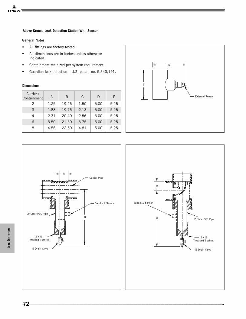
72
LEAK
DETE
CTIO
N
Above-Ground Leak Detection Station With Sensor
External Sensor
E
D
Dimensions
A B C D E
2 1.25 19.25 1.50 5.00 5.25
3 1.88 19.75 2.13 5.00 5.25
4 2.31 20.40 2.56 5.00 5.25
6 3.50 21.50 3.75 5.00 5.25
8 4.56 22.50 4.81 5.00 5.25
Carrier /Containment
A
Carrier Pipe
Saddle & Sensor
B
½ Drain Valve
2 x ½Threaded Bushing
2" Clear PVC Pipe
2" Clear PVC Pipe
2 x ½Threaded Bushing
½ Drain Valve
Saddle & Sensor
C
B
General Notes
• All fittings are factory tested.
• All dimensions are in inches unless otherwise indicated.
• Containment tee sized per system requirement.
• Guardian leak detection – U.S. patent no. 5,343,191.

73
LEAKD
ETECTION
Above-Ground Leak Detection Station
Dimensions
A B C D E
2 1.25 19.25 1.50 5.00 5.25
3 1.88 19.75 2.13 5.00 5.25
4 2.31 20.40 2.56 5.00 5.25
6 3.50 21.50 3.75 5.00 5.25
8 4.56 22.50 4.81 5.00 5.25
Carrier /Containment
A
B
Carrier Pipe
2" Clear PVC Pipe
2 x ½ Threaded Bushing
½ Drain Valve ½ Drain Valve
2 x ½ Threaded Bushing
2" Clear PVC PipeB
C
General Notes
• All fittings are factory tested.
• All dimensions are in inches unless otherwise indicated.
• Containment tee sized per system requirement.

74
LEAK
DETE
CTIO
N
Leak Detection Cable
Access Tee
Although several different cable leak detection systems are on the market, they all operate on similar principles. The leakdetection cable is manufactured from corrosion-resistant material and rests on the bottom of the piping. Should any chemicalspillage occur, the cable will automatically detect the leak.
CABLE LEAK DETECTION

75
LEAKD
ETECTION
General Requirements For Leak Detection Cable
These general requirements are intended as a guide only andare not a substitute for the detailed instructions given byIPEX. IPEX recommends that in all cases, the designer andinstaller contact us for specific design installation advice.
1. The leak detection cable should be installed in the gapbetween the primary and secondary pipe sections, at the “6o’clock position”.
2. Access points to the pipe are required for properinstallation of the sensing cable and for future modification.IPEX recommends that an access tee should be placed at thefollowing points in the system:
• After each 180 degrees of pipe bend.
• Every 250 to 400 feet of straight pipe run.
• Local to each wye.
• At every cable entry and termination point.
IPEX manufactures an access tee to meet the aboverequirements.
Secondary Pipe
Pipe Support
Primary Pipe
Sensing Cable
250 - 400'
Blind flange
Gasket
Flange
Pipe Spool
Secondary Coupling
Access Tee

76
LEAK
DETE
CTIO
N
3. A cable service loop (i.e. an extra loop of sensing cablereaching to the top of the access) should be provided to alloweasy access to the cable connector.
4. The system should be free of contaminants and waterbefore installing the leak detection cable. Failure to removecontaminants such as oil, grease or other non-evaporativesubstances may cause the cable to be permanently in the alarmmode.
IPEX systems are shipped to the site complete with endprotection to minimize the amount of contamination of thepiping.
5. During installation, the pull rope, (which should be aminimum of 1/4" and 300 lbs. pulling strength), should extendat least three feet from the access point. Tie or tape the pullrope to the top of the access point.
After a successful hydrostatic testing of the primary pipe, theleak detection cable can be installed, as required, followedby joining the secondary pipe.
Leak detection cable should be installed in full compliancewith the manufacturer’s recommendations. Nylon pulling-rope, similar to ski tow rope, is normally recommended topull the leak detection cable through the piping system. Therope should be at least 1/4" diameter and knot-free. IPEX pre-inserts twine into every Encase component to assist theinstaller in pulling the rope through the piping, prior toinstalling the leak detection cable.
The leak detection cable must always be installed after theprimary pipe has been tested. It should not be installed asthe primary joints are being made, since site conditions, orleaking joints during testing, may wet the cable and causeinstallation/operational problems. The cable must remain dryduring installation. After inserting the leak detection cable,the secondary joints can be made.
Cable

77
SPECIALTY
COM
PONEN
TS
NEUTRATANK®
Neutralization Tanks
IPEX double containment NeutratanksTM are designed for usein gravity-flow systems where neutralization of chemicals isrequired prior to discharge into public sewers. The double-contained feature of the IPEX Neutratank ensures that, in theevent of a failure of the primary tank, the secondary tank willaccommodate any spill until the necessary repairs can bemade. Neutratanks are molded from chemically resistantpolyethylene or polypropylene and are custom-fabricated tosuit individual customers’ requirements regarding inlet, outletand vent connections.
Double contained Neutratanks are manufactured in secondarysizes up to 2,000 gallons, with primary tanks as small as 5gallons. IPEX will manufacture double containment tanks inthe primary/secondary combinations that the individualcustomer requires. Tanks in sizes up to 275 gallons can beequipped with either an easy access cover, or a bolted stylecover. Further details on both styles of tanks are shown in theIPEX Acid Waste Piping Systems Technical Manual.
In all cases, IPEX recommends that Neutratanks are installedin a concrete vault to enable easy access for drainage andrepair, and that some method of automatic leak detection isemployed.
IPEX’s exclusive “EZ Access Cover” is an assembly that ispermanently welded to the top of the tank. The assemblyincludes a threaded cover, collar and neoprene seal. The EZAccess Cover allows for quick and easy removal of the tankcover and facilitates quick installation, inspection andmaintenance. Using the EZ Access Cover eliminates thetedious and time-consuming chores associated withtraditional tank covers, including aligning the gasket andsecuring its numerous bolts.
SECTION TEN: SPECIALTY COMPONENTS

78
SPEC
IALT
Y
COM
PON
ENTS
Encase is designed in modular form to allow contractors totake stock items and assemble them with the minimal sitefabrication.
Where a contractor requires a pre-assembled manifold(similar to that shown below), these can be provided by IPEXupon receipt of dimensional drawings. This type of customfabrication can be provided in lengths up to 40 feet.
Order a composite assembly where two or more fittings arepre-assembled at IPEX to your specifications. These can bedone in lengths up to 40 feet.
Encase is also available in flame-retardant materials. ContactIPEX’s customer service department for pricing.
ENCASETM
Butt Weld

79
SPECIALTY
COM
PONEN
TS
IPEX also provides a number of specialty components andservices. These include:
• Ball Valve - Manual & Actuated (Electric or Pneumatic)
• Check Valves
• Expansion Loops
• Expansion Ells
• Access Tees
• Sub-Assemblies (IPEX provides isometric and detail drawings of system)
• Detailed Stress Analysis by licensed professional engineer
Consult IPEX for more detailed information.
GUARDIAN/CUSTOMGUARDTM

80
This page intentionally
left blank

81
SPECIFICATION
S
ENCASETM
Encase Long Form
General
Acid waste double containment drain lines, as shown ondrawings, shall be Encase, manufactured by IPEX, with nosubstitutions. Pipe and fittings shall be manufactured fromSchedule 40 polypropylene and joined by the Enfusionmethod.
Material
Pipe, fittings, internal pipe supports and anchor plates shallbe manufactured from Type 1 homopolymer or Type 2copolymer polypropylene material as described in ASTM D4101.
Pipe and Fittings – Construction
All pipe fittings shall be factory assembled and of unitizedconstruction, with the primary and secondary componentsintegrally anchored together to prevent movement of theprimary pipe/fitting within the containment pipe/fitting. Allpiping components shall be manufactured to Schedule 40dimensions. The primary pipe shall be adequately supportedby means of support plates welded to the primary pipe.Anchor plates shall be provided at each end of thepipe/fitting section to restrain pipe expansion. All anchorplates must be mechanically located in a machined recesson the inside of each secondary pipe/fitting and welded toboth the primary and secondary pipe/fitting sections.
Factory Welded Joints
All factory joints shall be made either by butt fusion orEnfusion. Joining by means of fillet welding is expresslyforbidden.
Site Joints
All site joints shall be made using Enfusion couplings,manufactured from polypropylene with a nickel/chromeresistance wire, molded in place. Components with copperwire elements are prohibited. Solvent, butt-welded or fillet-welded site joints are also prohibited.
Installation
Installation shall be in accordance with the contractdrawings, the manufacturer’s recommendations and thelocal plumbing code. The entire installation shall beinstalled in proper alignment and free of stress.
Testing
The system shall be tested in accordance with themanufacturer’s recommendations and the local plumbingcode. The primary pipe shall be tested prior to making thesecondary joints.
If Secondary pipe cannot be hydro-tested, as determinedby the engineer or authority having jurisdiction, then theuse of nitrogen or air at a MAXIMUM 5 psi (gauge) shallbe allowed. It is imperative that a working-pressureregulator be used during the pneumatic test to ensure thatover-pressurization of the PVC, beyond 5 psi, cannot occur.The following must also be noted: Air or nitrogen underpressure is compressed and therefore poses a potentialhazard. If a failure of the pipe or fitting occurs during suchtest, the air exits at the failure point and expands rapidly.This increase in velocity can cause the system to fail in acatastrophic mode. Therefore during such air test allpersonnel involved in the test or present in the testsurrounding area must be aware of such a possibility andtake all necessary precautions. Precautions include, butare not limited to, taking extreme care not to impact ordamage the system in any way.
Such procedure is a limited exception to IPEX standardpolicy which forbids the use of its rigid systems with anycompressed gases.
Encase Short Form
Acid waste double containment drain lines shall be Encase, as manufactured by IPEX, with no substitutions. Pipe andfittings shall be manufactured from Schedule 40, ASTM D 4101 Type 1 homopolymer or Type 2 Copolymer polypropylene.Joining shall be made using Enfusion couplings and a nickel/chrome wire molded in place. All pipe fittings shall be factoryassembled, with Enfusion, or butt fusion welds, and be of unitized construction, with primary and secondary componentsintegrally anchored together to control expansion and contraction. All primary joints shall be pressure tested and inspected,in accordance with the manufacturer’s instructions and any local plumbing codes, prior to making any secondary joints.
SECTION ELEVEN: SPECIFICATIONS

82
SPEC
IFIC
ATIO
NS
PVC Schedule 80/PVC Schedule 80 Double Containment PipingSystem
General
Scope of Work
Furnish all labor, materials, equipment and incidentalsrequired to install a Guardian Schedule 80 PVC(Primary)/Schedule 80 PVC (Secondary) double containmentpiping, valves and appurtenances for complete systems asshown on the drawings and as specified herein.
Description of Systems
_____% Chemical Names (To be inserted)
Submittals
Shop drawings shall be submitted to the engineer andinclude details of pipe fabrications (including supportingdevices, method of attachment, spacing, etc.), prefabricateddouble containment fitting dimensions, starting andterminating connections, high-point vent and low-point draindetails for the secondary containment, valves andaccessories. Submit joint details, methods and location ofsupports, and all other pertinent technical data for all pipingto be furnished.
Qualifications
The double containment piping system shall be a Guardianprefabricated system as manufactured by IPEX. The systemshall be fabricated, installed and tested in accordance withIPEX’s recommendations and as specified herein and shall besuitable for the intended service. Manufacturer shall have aminimum of five (5) years experience. Contractor shall notdesign and/or fabricate the piping system.
Products
General
Each contained piping system shall consist of Xirtec 140™schedule 80 PVC primary piping system supported within aXirtec 140™ Schedule 80 PVC secondary containmenthousing. Carrier fitting sizes 1/2" through 4" will use Centra-Lok [U.S. Patent No. 5,398,973] molded supportsminimizing the number of field (factory assembled) fittingjoints. Carrier sizes 6" and larger will use IPEX standardpolypropylene fitting discs to support and centralize. Eachsystem shall be provided with suitable drains and vents andbe designed to provide complete drainage of both the primaryand secondary containment piping. Interstitial supportingdevices shall be made from Polypropylene Centra-Guidesupports and shall be provided within the secondarycontainment pipe, and shall be designed to allow continuousdrainage in the annular space to the drain points. Drainfittings shall be designed to allow a valve attachment to bemade so that the secondary containment compartment maybe readily drained and manually checked for leaks.
Materials
The primary pipe and fittings shall be manufactured fromXirtec140 schedule 80 materials as manufactured by IPEXand as listed by ASTM and ANSI.
The secondary containment pipe and fittings shall bemanufactured from Xirtec140 schedule 80 PVC materials asmanufactured by IPEX and as listed by ASTM and ANSI.
All listed primary pipe and containments shall be IPEX’sXirtec140 schedule 80 materials. Pipe shall have schedule80 PVC pipe thickness. All listed pressure fittings shall beschedule 80 PVC according to ASTM D-2467 specifications.All other unlisted components intended for use as pressureretaining components shall have sufficient thickness andreinforcement so as to be able to maintain the same pressureratings as the equivalent schedule 80 PVC pipe.
Interstitial supporting devices used to center and support theprimary piping within the secondary containment piping shallbe manufactured from Polypropylene Centra-Guide supports,according to ASTM and ANSI.
All listed secondary containment pipe and fittings shall beIPEX’s Xirtec140 schedule 80 materials as manufactured byIPEX. Pipe shall have schedule 80 thickness according toASTM D-1784. All listed pressure fittings shall be schedule80 according to ASTM D-2467. All other unlistedcomponents intended for use as pressure retainingcomponents shall have sufficient thickness andreinforcement so as to be able to maintain the same pressureratings as the equivalent schedule 80 PVC pipe.
All fittings will be pre-assembled (1/2" through 4" carrierfittings will be supported with the Centra-Lok [U.S. PatentNo. 5,398,973] system, 6" and larger carrier will besupported with IPEX standard Polypropylene fitting discs)and pretested by the manufacturer (IPEX).
GUARDIAN

83
SPECIFICATION
S
Execution
Installation
All installation procedures shall be according to themanufacturer’s (IPEX) specific recommendations. Themanufacturer shall furnish the services of a competentrepresentative to supervise the contractor’s personnel duringthe start of the installation.
All secondary containment joints shall be solvent-cementedjoints using heavy body-slow set PVC cement ASTM D-2564,made in accordance with ASTM D-2855 procedure. Thesplitting and re-welding of fittings shall not be permitted.The use of hot gas welding for pressure-retaining joints shallbe kept to those locations where deemed necessary by IPEX.
All contractor personnel that will prepare solvent cementedjoints shall be qualified for such bonding practices accordingto the bonding qualifications procedures described in ASMEB 31.3, Chapter VII for bonding of plastic piping.
Cleaning and Testing
Upon completing installation, the primary piping system shallbe hydrostatically tested at 150% of the system designpressure for a period of one hour. Additionally, the systemmay be tested during the installation at intervals to bedetermined by the manufacturer (IPEX).
If Secondary pipe cannot be hydro-tested, as determined bythe engineer or authority having jurisdiction, then the use ofnitrogen or air at a MAXIMUM 5 psi (gauge) shall be allowed.The external joint should be soaped and visually inspectedfor leaks.
Both the preliminary and final tests shall be performed instrict accordance with the recommendations of themanufacturer (IPEX) including the sequence and duration ofsuch tests.
Warning
It is imperative that a working-pressure regulator be used duringthe pneumatic test to ensure that over-pressurization of the PVC,beyond 5 psi, cannot occur. The following must also be noted:Air or nitrogen under pressure is compressed and thereforeposes a potential hazard. If a failure of the pipe or fitting occursduring such test, the air exits at the failure point and expandsrapidly. This increase in velocity can cause the system to fail ina catastrophic mode. Therefore during such air test all personnelinvolved in the test or present in the test surrounding area mustbe aware of such a possibility and take all necessaryprecautions. Precautions include, but are not limited to, takingextreme care not to impact or damage the system in any way.Such procedure is a limited exception to IPEX standard policywhich forbids the use of its rigid systems with any compressedgases, unless the product(s) is specifically designed for theconveyance of compressed gases.
Following installation of the systems, the primary pipingsystem shall be flushed clean. The contractor shall checkthe operation of all valves, leak detection devices andappurtenances.
The annular space shall be purged of moisture containing airby replacing the volume of air with clean, dry nitrogen.
Leak Detection – U.S. Patent No. 5,343,191
Provide and install at each zone a density sensor stationconsisting of an external clip-on sensor, drip leg and drainvalve with hose connection and/or riser and sensor extensionhandle. Each sensor shall have an LED testing lamp,adjusting potentiometer and be removable for periodictesting. Sensor shall not penetrate the containment pipingjacket. Control console shall be housed in a NEMA IVenclosure, operating on 120 VAC and supplies 24 VDC tozone sensors. Console shall have alarm lamps, pilot lamp,test buttons and mute switch. Console shall also have acommon audible alarm and external output switch foraccessory alarms. Leak detection system shall be Centra-Guard™ as manufactured by IPEX.

84
SPEC
IFIC
ATIO
NS
GUARDIAN
PVC Schedule 80/PVC Schedule 40 Double Containment PipingSystem
General
Scope of Work
Furnish all labor, materials, equipment and incidentalsrequired to install a Guardian Schedule 80 PVC(Primary)/Schedule 40 PVC (Secondary) double containmentpiping, valves and appurtenances for complete systems asshown on the drawings and as specified herein.
Description of Systems
_____% Chemical Names (To be inserted)
Submittals
Shop drawings shall be submitted to the engineer andinclude details of pipe fabrications (including supportingdevices, method of attachment, spacing, etc.), prefabricateddouble containment fitting dimensions, starting andterminating connections, high-point vent and low-point draindetails for the secondary containment, valves andaccessories. Submit joint details, methods and location ofsupports, and all other pertinent technical data for all pipingto be furnished.
Qualifications
The double containment piping system shall be a Guardianprefabricated system as manufactured by IPEX. The systemshall be fabricated, installed and tested in accordance withIPEX’s recommendations and as specified herein and shall besuitable for the intended service. Manufacturer shall have aminimum of five (5) years experience. Contractor shall notdesign and/or fabricate the piping system.
Products
General
Each contained piping system shall consist of Xirtec 140™schedule 80 PVC primary piping system supported with aXirtec 140™ Schedule 40 PVC secondary containmenthousing. Carrier fitting sizes 1/2" through 4" will use Centra-Lok [U.S. Patent No. 5,398,973] molded supportsminimizing the number of (factory assembled) fitting joints.Carrier sizes 6" and larger will use IPEX standardpolypropylene fitting discs to support and centralize. Eachsystem shall be provided with suitable drains and vents andbe designed to provide complete drainage of both the primaryand secondary containment piping. Interstitial supportingdevices shall be made from Polypropylene Centra-GuideTM
supports and shall be provided within the secondarycontainment pipe, and shall be designed to allow continuousdrainage in the annular space to the drain points. Drainfittings shall be designed to allow a valve attachment to bemade so that the secondary containment compartment maybe readily drained and manually checked for leaks.
Materials
The primary pipe and fittings shall be manufactured fromXirtec140 schedule 80 materials as manufactured by IPEXand as listed by ASTM and ANSI.
The secondary containment pipe and fittings shall bemanufactured from Xirtec140 schedule 40 PVC materials asmanufactured by IPEX and as listed by ASTM and ANSI.
All listed primary pipe shall be Xirtec™140 schedule 80materials. Pipe shall have schedule 80 PVC pipe thickness.All listed pressure fittings shall be schedule 80 PVCaccording to ASTM D-2467 specifications. All other unlistedcomponents intended for use as pressure retainingcomponents shall have sufficient thickness andreinforcement so as to be able to maintain the same pressureratings as the equivalent schedule 80 PVC pipe.
Interstitial supporting devices used to center and support theprimary piping within the secondary containment piping shallbe manufactured from Polypropylene Centra-Guide supports,according to ASTM and ANSI.
All listed secondary containment pipe and fittings shall beXirtec™140 schedule 40 materials as manufactured by IPEX.Pipe shall have schedule 40 thickness according to ASTM D-2467. All other unlisted components intended for use aspressure retaining components shall have sufficientthickness and reinforcement so as to be able to maintain thesame pressure ratings as the equivalent schedule 40 PVCpipe.
All fittings will be pre-assembled (1/2" through 4" carrierfittings will be supported with the Centra-Lok [U.S. PatentNo. 5,398,973] system, 6" and larger carrier will besupported with standard Polypropylene fittings discs) andpretested by the manufacturer (IPEX).

85
SPECIFICATION
S
Execution
Installation
All installation procedures shall be according to themanufacturer’s (IPEX) specific recommendations. Themanufacturer shall furnish the services of a competentrepresentative to supervise the contractor’s personnel duringthe start of the installation.
All secondary containment joints shall be solvent-cementedjoints using heavy body-slow set PVC cement ASTM D-2564,made in accordance with ASTM D-2855 procedure. Thesplitting and re-welding of fittings shall not be permitted.The use of hot gas welding for pressure-retaining joints shallbe kept to those locations where deemed necessary by IPEX.
All contractor personnel that will prepare solvent cementedjoints shall be qualified for such bonding practices accordingto the bonding qualifications procedures described in ASMEB 31.3, Chapter VII for bonding of plastic piping.
Cleaning and Testing
Upon completing installation, the primary piping system shallbe hydrostatically tested at 150% of the system designpressure for a period of one hour. Additionally, the systemmay be tested during the installation at intervals to bedetermined by the manufacturer (IPEX).
If Secondary pipe cannot be hydro-tested, as determined bythe engineer or authority having jurisdiction, then the use ofnitrogen or air at a MAXIMUM 5 psi (gauge) shall be allowed.The external joint should be soaped and visually inspectedfor leaks.
Both the preliminary and final tests shall be performed instrict accordance with the recommendations of themanufacturer (IPEX) including the sequence and duration ofsuch tests.
Warning
It is imperative that a working-pressure regulator be used duringthe pneumatic test to ensure that over-pressurization of the PVC,beyond 5 psi, cannot occur. The following must also be noted:Air or nitrogen under pressure is compressed and thereforeposes a potential hazard. If a failure of the pipe or fitting occursduring such test, the air exits at the failure point and expandsrapidly. This increase in velocity can cause the system to fail ina catastrophic mode. Therefore during such air test all personnelinvolved in the test or present in the test surrounding area mustbe aware of such a possibility and take all necessaryprecautions. Precautions include, but are not limited to, takingextreme care not to impact or damage the system in any way.Such procedure is a limited exception to IPEX standard policywhich forbids the use of its rigid systems with any compressedgases, unless the product(s) is specifically designed for theconveyance of compressed gases.
Following installation of the systems, the primary pipingsystem shall be flushed clean. The contractor shall checkthe operation of all valves, leak detection devices andappurtenances.
The annular space shall be purged of moisture containing airby replacing the volume of air with clean, dry nitrogen.
Leak Detection – U.S. Patent No. 5,343,191
Provide and install at each zone a density sensor stationconsisting of an external clip-on sensor, drip leg and drainvalve with hose connection and/or riser and sensor extensionhandle. Each sensor shall have an LED testing lamp,adjusting potentiometer and be removable for periodictesting. Sensor shall not penetrate the containment pipingjacket. Control console shall be housed in a NEMA IVenclosure, operating on 120 VAC and supplies 24 VDC tozone sensors. Console shall have alarm lamps, pilot lamp,test buttons and mute switch. Console shall also have acommon audible alarm and external output switch foraccessory alarms. Leak detection system shall be Centra-Guard™ as manufactured by IPEX.

86
SPEC
IFIC
ATIO
NS
CUSTOMGUARDTM
Schedule 40 A-53 Carbon Steel/UL FRP Double ContainmentPiping System
General
Scope of Work
Furnish all labor, materials, equipment and incidentalsrequired to install a CustomGuard™ Schedule 40 A-53Carbon Steel (Primary)/UL FRP (Secondary) doublecontainment piping, valves and appurtenances for completesystems as shown on the drawings and as specified herein.
Description of Systems
_____% Chemical Names (To be inserted)
Submittals
Shop drawings shall be submitted to the engineer andinclude details of pipe fabrications (including supportingdevices, method of attachment, spacing, etc.), prefabricateddouble containment fitting dimensions, starting andterminating connections, high-point vent and low-point draindetails for the secondary containment, valves andaccessories. Submit joint details, methods and location ofsupports and all other pertinent technical data for all pipingto be furnished. Manufacturer shall submit mill certs for allmetal piping used in this project.
Qualifications
The double containment piping systems shall be aCustomGuard™ prefabricated system as manufactured byIPEX. The system shall be fabricated, installed and tested inaccordance with IPEX’s recommendations and as specifiedherein and shall be suitable for the intended service.Manufacturer shall have a minimum of five (5) yearsexperience. Contractor shall not design and/or fabricate thepiping system.
Products
General
Each contained piping system shall consist of Schedule 40A-53 Carbon Steel primary piping system supported within aUL FRP secondary containment housing. Each system shallbe provided with suitable drains and vents and be designedto provide complete drainage of both the primary andsecondary containment piping. Interstitial supporting devicesshall be made from Polypropylene Centra-Guide supports andshall be provided within the secondary containment pipe, andshall be designed to allow continuous drainage in the annularspace to the drain points. Drain fittings shall be designed toallow a valve attachment to be made so that the secondarycontainment compartment may be readily drained andmanually checked for leaks.
Materials
The primary pipe and fittings shall be manufactured from A-53 Carbon Steel materials as listed by ASTM and ANSI.
The secondary containment pipe and fittings shall be ULFRP.
All listed primary pipe and containments shall be Schedule40 materials. Pipe shall have Schedule 40 steel pipethickness according to ANSI. All listed pressure fittings shallbe Schedule 40 according to ANSI. All other unlistedcomponents intended for use as pressure retainingcomponents shall have sufficient thickness andreinforcement so as to be able to maintain the same pressurerating as the equivalent Schedule 40 steel pipe.
Interstitial supporting devices used to center and support theprimary piping within the secondary containment pipe andfittings shall meet ASTM specifications D-2310, D-2992, D-2996 and MIL 29206. Containment fittings shall havecarrier components pre-assembled, supported and tested.Carrier fittings will be pre-beveled, ready for field welding.Containment fittings shall have spigot ends to allow for aclosure coupling to be installed after primary system ispressure tested.
All fittings will be pre-assembled and pretested by themanufacturer of CustomGuard™ (IPEX).

87
SPECIFICATION
S
Execution
Installation
All installation procedures shall be according to themanufacturer’s (IPEX) specific recommendations. Themanufacturer shall furnish the services of a competentrepresentative to supervise the contractor’s personnel duringthe start of the installation.
All secondary containment joints shall be solvent-cementedjoints using heavy body-slow set PVC cement ASTM D-2564,made in accordance with ASTM D-2855 procedure. Thesplitting and re-welding of fittings shall not be permitted.The use of hot gas welding for pressure-retaining joints shallbe kept to those locations where deemed necessary by IPEX.
All contractor personnel that will prepare solvent cementedjoints shall be qualified for such bonding practices accordingto the bonding qualifications procedures described in ASMEB 31.3, Chapter VII for bonding of plastic piping.
Cleaning and Testing
Upon completing installation, the primary piping system shallbe hydrostatically tested at 150% of the system designpressure for a period of one hour.
Upon completing the installation, the secondary containmentpiping system shall be pneumatically tested at a minimumduration of 21/2 hours. The external joints should be soapedand visually inspected for leaks. It is imperative that aworking pressure regulator be used during the pneumatic testto insure that over-pressurization of the UL FRP, beyond 5psi cannot occur. Also, all precautions should be taken toprotect against the hazards of a possible brittle fracture ofUL FRP under compressed gas.
Following installation of the systems, the primary pipingsystem shall be flushed clean. The contractor shall check theoperation of all valve, leak detection devices andappurtenances.
Leak Detection – U.S. Patent No. 5,343,191
Provide and install at each zone a density sensor stationconsisting of an external clip-on sensor, drip leg and drainvalve with hose connection and/or riser and sensor extensionhandle. Each sensor shall have an LED testing lamp,adjusting potentiometer and be removable for periodictesting. Sensor shall not penetrate the containment pipingjacket. Control console shall be housed in a NEMA IVenclosure, operating on 120 VAC and supplies 24 VDC tozone sensors. Console shall have alarm lamps, pilot lamp,test buttons and mute switch. Console shall also have acommon audible alarm and external output switch foraccessory alarms. Leak detection system shall be Centra-Guard™ as manufactured by IPEX.

88
SPEC
IFIC
ATIO
NS
CUSTOMGUARDTM
Schedule 40 A-53 Carbon Steel/Schedule 80 PVC DoubleContainment Piping System
General
Scope of Work
Furnish all labor, materials, equipment and incidentalsrequired to install a Cutsom-Guard™ Schedule 40 A-53Carbon Steel (Primary)/Sch 80 PVC (Secondary) doublecontainment piping, valves and appurtenances for completesystems as shown on the drawings and as specified herein.
Description of Systems
_____% Chemical Names (To be inserted)
Submittals
Shop drawings shall be submitted to the engineer andinclude details of pipe fabrications (including supportingdevices, method of attachment, spacing, etc.), prefabricateddouble containment fitting dimensions, starting andterminating connections, high-point vent and low-point draindetails for the secondary containment, valves andaccessories. Submit joint details, methods and location ofsupports, and all other pertinent technical data for all pipingto be furnished. Manufacturer shall submit mill certs for allmetal piping used in this project.
Qualifications
The double containment piping systems shall be aCustomGuard™ prefabricated system as manufactured byIPEX. The system shall be fabricated, installed and tested inaccordance with IPEX’s recommendations and as specifiedherein and shall be suitable for the intended service.Manufacturer shall have a minimum of five (5) yearsexperience. Contractor shall not design and/or fabricate thepiping system.
Products
General
Each contained piping system shall consist of Schedule 40A-53 Carbon steel primary piping system supported within aXirtec 140™ PVC Schedule 80 secondary containmenthousing. Each system shall be provided with suitable drainsand vents and be designed to provide complete drainage ofboth the primary and secondary containment piping.Interstitial supporting devices shall be made fromPolypropylene Centra-Guide supports and shall be providedwithin the secondary containment pipe, and shall bedesigned to allow continuous drainage in the annular spacethe drain points. Drain fittings shall be designed to allow avalve attachment to be made so that the secondarycontainment compartment may be readily drained andmanually checked for leaks.
Materials
The primary pipe fittings shall be manufactured fromSchedule 80 PVC materials as manufactured by IPEX and aslisted by ASTM and ANSI.
The secondary containment pipe and fittings shall bemanufactured from Schedule 80 PVC materials asmanufactured by IPEX and as listed by ASTM and ANSI.
All listed primary pipe shall be Schedule 40 materials. Pipeshall have Schedule 40 steel pipe thickness according toANSI. All listed pressure fittings shall be Schedule 40according to ANSI. All other unlisted components intendedfor use as pressure retaining components shall havesufficient thickness and reinforcement so as to be able tomaintain the same pressure ratings as the equivalentSchedule 40 steel pipe.
Interstitial supporting devices used to center and support theprimary piping within the secondary containment piping shallbe manufactured from Polypropylene Centra-Guide supports,according to ASTM and ANSI.
All listed secondary containment pipe and fittings shall beSchedule 80 materials as manufactured by IPEX. Pipe shallhave Schedule 80 thickness according to ASTM D-1784 Type1, Grade 1. All listed pressure fittings shall be schedule 80according to ASTM D-2466. All other unlisted componentsintended for use as pressure retaining components shall havesufficient thickness and reinforcement so as to be able tomaintain the same pressure ratings as the equivalentSchedule 80 PVC pipe.
All fittings will be pre-assembled and pretested by themanufacturer of Cutsom-Guard™ (IPEX).

89
SPECIFICATION
S
Execution
Installation
All installation procedures shall be according to themanufacturer’s (IPEX) specific recommendations. Themanufacturer shall furnish the services of a competentrepresentative to supervise the contractor’s personnel duringthe start of the installation.
All secondary containment joints shall be solvent-cementedjoints using heavy body-slow set PVC cement ASTM D-2564,made in accordance with ASTM D-2855 procedure. Thesplitting and re-welding of fittings shall not be permitted.The use of hot gas welding for pressure-retaining joints shallbe kept to those locations where deemed necessary by IPEX.
All contractor personnel that will prepare solvent cementedjoints shall be qualified for such bonding practices accordingto the bonding qualifications procedures described in ASMEB 31.3, Chapter VII for bonding of plastic piping.
Cleaning and Testing
Upon completing installation, the primary piping system shallbe hydrostatically tested at 150% of the system designpressure for a period of one hour. Additionally, the systemmay be tested during the installation at intervals to bedetermined by the manufacturer (IPEX).
If Secondary pipe cannot be hydro-tested, as determined bythe engineer or authority having jurisdiction, then the use ofnitrogen or air at a MAXIMUM 5 psi (gauge) shall be allowed.The external joint should be soaped and visually inspectedfor leaks.
Both the preliminary and final tests shall be performed instrict accordance with the recommendations of themanufacturer (IPEX) including the sequence and duration ofsuch tests.
Warning
It is imperative that a working-pressure regulator be used duringthe pneumatic test to ensure that over-pressurization of the PVC,beyond 5 psi, cannot occur. The following must also be noted:Air or nitrogen under pressure is compressed and thereforeposes a potential hazard. If a failure of the pipe or fitting occursduring such test, the air exits at the failure point and expandsrapidly. This increase in velocity can cause the system to fail ina catastrophic mode. Therefore during such air test all personnelinvolved in the test or present in the test surrounding area mustbe aware of such a possibility and take all necessaryprecautions. Precautions include, but are not limited to, takingextreme care not to impact or damage the system in any way.Such procedure is a limited exception to IPEX standard policywhich forbids the use of its rigid systems with any compressedgases, unless the product(s) is specifically designed for theconveyance of compressed gases.
Following installation of the systems, the primary pipingsystem shall be flushed clean. The contractor shall checkthe operation of all valves, leak detection devices andappurtenances.
The annular space shall be purged of moisture containing airby replacing the volume of air with clean, dry nitrogen.
Leak Detection – U.S. Patent No. 5,343,191
Provide and install at each zone a density sensor stationconsisting of an external clip-on sensor, drip leg and drainvalve with hose connection and/or riser and sensor extensionhandle. Each sensor shall have an LED testing lamp,adjusting potentiometer and be removable for periodictesting. Sensor shall not penetrate the containment pipingjacket. Control console shall be housed in a NEMA IVenclosure, operating on 120 VAC and supplies 24 VDC tozone sensors. Console shall have alarm lamps, pilot lamp,test buttons and mute switch. Console shall also have acommon audible alarm and external output switch foraccessory alarms. Leak detection system shall be Centra-Guard™ as manufactured by IPEX.

90
This page intentionally
left blank

91
CONVERSION CHARTS
Contents of Pipe
Dia.in.
1/45/16
3/87/16
1/29/16
5/811/16
3/413/16
7/815/16
111/411/213/42
21/421/223/43
31/431/233/44
Dia.ft.
.0208
.0260
.0313
.0365
.0417
.0469
.0521
.0573
.0625
.0677
.0729
.0781
.0833
.1042
.1250
.1458
.1667
.1875
.2083
.2292
.2500
.2708
.2917
.3125
.3333
ft.3
Also Areain. ft.2
.0003
.0005
.0008
.0010
.0014
.0017
.0021
.0026
.0031
.0036
.0042
.0048
.0055
.0085
.0123
.0168
.0218
.0276
.0341
.0413
.0491
.0576
.0668
.0767
.0873
U.S. Gal.(231 in.3)
.0026
.0040
.0057
.0078
.0102
.0129
.0159
.0193
.0230
.0270
.0312
.0359
.0408
.0638
.0918
.1250
.1632
.2066
.2550
.3085
.3673
.4310
.4998
.5738
.6528
Dia.in.
41/441/243/45
51/451/253/46
61/461/263/47
71/471/273/48
81/481/283/49
91/491/293/410
101/4
Dia.ft.
.3542
.3750
.3958
.4167
.4375
.4583
.4792
.5000
.5208
.5417
.5625
.5833
.6042
.6250
.6458
.6667
.6875
.7083
.7292
.7500
.7708
.7917
.8125
.8333
.8542
ft.3
Also Areain. ft.2
.0985
.1105
.1231
.1364
.1503
.1650
.1803
.1963
.2130
.2305
.2485
.2673
.2868
.3068
.3275
.3490
.3713
.3940
.4175
.4418
.4668
.4923
.5185
.5455
.5730
U.S. Gal.(231 in.3)
.7370
.8263
.92051.0201.1241.2341.3491.4691.5941.7241.8591.9992.1442.2952.4502.6112.7772.9483.1253.3053.4923.6823.8794.0814.286
Dia.in.
101/2103/411
111/4111/2113/412
121/213
131/214
141/215
151/216
161/2
Dia.ft.
.8750
.8958
.9167
.9375
.9583
.97921.0001.0421.0831.1251.1671.2081.2501.2921.3331.375
ft.3
Also Areain. ft.2
.6013
.6303
.6600
.6903
.7213
.7530
.7854
.8523
.9218
.99401.0691.1471.2271.3101.3961.485
U.S. Gal.(231 in.3)
4.4984.7144.9375.1635.3955.6335.8766.3756.8957.4357.9978.5789.1809.801
10.44011.110
Capacities in Cubic Feet and in United States Gallons (231 Cubic Inches) per Foot of Length
For 1 Foot Length For 1 Foot Length For 1 Foot Length
Volume
Volume of a pipe is computed by: V = 1/4 ID2 x p x L x 12
Where: V = volume (in cubic inches)ID = inside diameter (in inches)p = 3.14159L = length of pipe (in feet)
Weight
1 U.S. gallon @ 50°F....... 8.33 lbs. x sg1 cubic foot .................... 62.35 lbs. x sg...................................... 7.48 U.S. gal.1 cu. ft. of water @ 50°F . 62.41 lbs.1 cu. ft. of water @ 39.2°F 62.43 lbs.(39.2°F is water temp. at its greatest density)1 kilogram ...................... 2.2 lbs.1 imperial gallon of water. 10.0 lbs.1 pound.......................... 12 U.S. gal ÷ sg...................................... .016 cu. ft. ÷ sg
Capacity or Flow
1 U.S. gallon per minute (gpm) 0.134 cfm......500 lb. per hr. x sp. gr.......500 lb. per hr. 1 gpm ÷ sp. gr.
1 cu. ft. per minute (cfm) ......449 gph1 cu. ft. per second (cfs) ......449 gpm1 acre foot per day ......227 gpm1 acre inch per hour ......454 gpm1 cubic meter per minute ......264.2 gpm1,000,000 gal. per day ......595 gpmBrake H.P. = (gpm) (total head in ft.) (specific gravity)
(3960) (pump eff.)
APPEN
DIXA

92
APPENDIX A
CON
VERSIONC
HARTS
lb./in.2
mm Hg (Torr)(at 0°C)
1.000
3.6127x10⁻²
1.4223x10⁻²
4.9116x10⁻¹
1.9337x10⁻²
1.4504x10⁵
1.4504x10⁻⁴
1.4224x101
1.4504x101
1.4696x101
6.9445x10⁻³
4.3352x10⁻¹
2.7680x101
1.0000
0.3937
1.3596x101
5.3525x10⁻¹
4.0147x10⁻⁴
4.0147x10⁻³
3.9371x10²
4.0147x10²
4.0679x10²
1.9223x10⁻¹
1.2000x101
7.0308x101
2.5400
1.0000
3.4532x101
1.3595
1.0197x10⁻³
1.0197x10⁻²
1.00003x10³
1.0197x10³
1.0333x10³
4.882x10⁻¹
3.0480x101
2.0360
7.3554x10⁻²
2.8958x10⁻²
1.0000
3.9370x10⁻²
2.9530x10⁻⁵
2.9530x10⁻⁴
2.8959x101
2.9530x101
2.9921x101
1.4139x10⁻²
8.826x10⁻¹
5.1715x101
1.8683
0.7355
2.5400x101
1.0000
7.5006x10⁻⁴
7.5006x10⁻³
7.3556x10²
7.5006x10²
7.6000x10²
3.591x10⁻¹
2.2419x101
6.8948x10⁴
2.49808x10³
9.8064x10²
3.3864x10⁴
1.3332x10³
1.0000
1.0000x101
9.8060x10⁵
1.0000x10⁶
1.0133x10⁶
4.7880x10²
2.9890x10⁴
6.8948x10³
2.4908x10²
9.8064x101
3.3864x10³
1.3332x10²
1.0000x10⁻¹
1.0000
9.8060x10⁴
1.0000x10⁵
1.0133x10⁵
4.7880x101
2.9890x10³
7.0306x10⁻²
2.5399x10⁻³
9.9997x10⁻⁴
3.4532x10⁻²
1.3595x10⁻³
1.0197x10⁻⁶
1.0197x10⁻⁵
1.0000
1.0197
1.0332
4.8824x10⁻⁴
3.0479x10⁻²
6.8947x10⁻²
2.4908x10⁻³
9.8064x10⁻⁴
3.3864x10⁻²
1.3332x10⁻³
1.0000x10⁻⁶
1.0000x10⁻⁵
9.8060x10⁻¹
1.0000
1.0113
4.7880x10⁻⁴
2.9890x10⁻²
6.8045x10⁻²
2.4582x10⁻³
9.6781x10⁻⁴
3.3421x10⁻²
1.3158x10⁻³
9.8692x10⁻⁷
9.8692x10⁻⁶
9.678x10⁻¹
9.8692x10⁻¹
1.0000
4.7254x10⁻⁴
2.9499x10⁻²
1.4400x10²
5.2022
2.0481
7.0727x101
2.7845
2.0886x10⁻³
2.0885x10⁻²
2.0482x10³
2.0885x10³
2.1162x10³
1.0000
6.2427x101
2.3067
8.3333x10⁻²
3.2808x10⁻²
1.1330
4.4605x10⁻²
3.3456x10⁻⁵
3.3456x10⁻⁴
3.2809x101
3.3456x101
3.3900x101
1.6019x10⁻²
1.0000
in.H20(at +39.2°F)
cm H20(at +4°C)
in. Hg(at +32°F)
dyne/cm2
(1m bar)newton/m2
(PASCAL)
kgm/cm2
bar
atm. (An)
ft. H20(at +39.2°F)
lb./ft.2
Given lb./in.2 in.H20(at +39.2°F)
cmH20(at +4°C)
in. Hg(at +32°F)
mm Hg (Torr)(at 0°C)
dyne/cm2
(1m bar)newton/m2
(PASCAL) kgm/cm2 bar atm. (An) lb./ft.2 ft.H20(at +39.2°F)
BY FACTOR TO OBTAIN
MU
LTIP
LY G
IVEN
NU
MBE
R OF
Fractions1/64
1/32
3/64
1/16
5/64
3/32
7/64
1/89/64
5/32
11/64
3/16
13/64
7/32
15/64
1/4
Decimals.015625
.03125
.046875
.0625
.078125
.09375
.109375
.125
.140625
.15625
.171875
.1875
.203125
.21875
.23475
.250
Milli-meters.397
.794
1.191
1.588
1.984
2.381
2.778
3.175
3.572
3.969
4.366
4.763
5.159
5.556
5.953
6.350
Fractions17/64
9/32
19/64
5/16
21/64
11/32
23/64
3/825/64
13/32
27/64
7/16
29/64
15/32
31/64
1/2
Decimals.265625
.28125
.296875
.3125
.328125
.34375
.359375
.375
.390625
.40625
.421875
.4375
.453125
.46875
.484375
.500
Milli-meters6.747
7.144
7.541
7.938
8.334
8.731
9.128
9.525
9.922
10.319
10.716
11.113
11.509
11.906
12.303
12.700
Fractions33/64
17/32
35/64
9/16
37/64
19/32
39/64
5/841/64
21/32
43/64
11/16
45/64
23/32
47/64
3/4
Decimals
.515625
.53125
.546875
.5625
.578125
.59375
.609375
.625
.640625
.65625
.671875
.6875
.703125
.71875
.734375
.750
Milli-meters13.097
13.494
13.891
14.288
14.684
15.081
15.478
15.875
16.272
16.669
17.066
17.463
17.859
18.256
18.653
19.050
Fractions49/64
25/32
51/64
13/16
53/64
27/32
55/64
7/857/64
29/32
59/64
15/16
61/64
31/32
63/64
1
Decimals.765625
.78125
.796875
.8125
.828125
.83475
.859375
.875
.890625
.90625
.921875
.9375
.953125
.96875
.984375
1.000
Milli-meters19.447
19.844
20.241
20.638
21.034
21.431
21.828
22.225
22.622
23.019
23.416
23.813
24.209
24.606
25.003
25.400
Inches Inches Inches Inches
DECIMAL AND MILLIMETER EQUIVALENTS OF FRACTIONS
PRESSURE CONVERSION
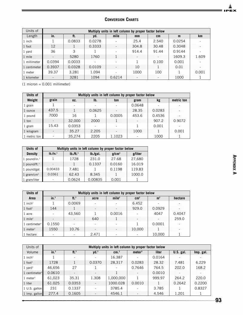
93
CONVERSION CHARTS
Units ofLength
1 inch
1 foot
1 yard
1 mile
1 millimeter
1 centimeter
1 meter
1 kilometer
in.1
1236-
0.03940.393739.37
-
ft.0.0833
13
52800.00330.03283.2813281
yd.0.02780.3333
11760
-0.01091.0941094
mile---1---
0.6214
mm25.4
304.8914.4
-1
101000
-
cm2.54030.4891.44
-0.100
1100
-
m0.02540.30480.91441609.30.0010.01
11000
km---
1.609--
0.0011
Units of Weight
1 grain
1 ounce
1 pound
1 ton
1 gram
1 kilogram
1 metric ton
grain1
437.57000
-15.43
--
oz.-1
1632,0000.035335.27
35,274
lb.-
0.06251
2000-
2.2052205
ton--
0.00051--
1.1023
gram0.064828.35453.6
-1
1000-
kg-
0.02830.4536907.20.001
11000
metric ton---
0.9072-
0.0011
Multiply units in left column by proper factor below
Units of Density
1 pound/in.3
1 pound/ft.3
1 pound/gal.
1 gram/cm3
1 gram/liter
lb./in.3
1
-
0.00433
0.0361
-
lb./ft.3
17281
7.48162.43
0.0624
lb./gal.231.0
0.13371
8.3450.00835
g/cm3
27.680.01600.1198
10.001
g/liter27,68016.019119.831000.0
1
Multiply units in left column by proper factor below
(1 micron = 0.001 millimeter)
Units of Area
1 inch2
1 foot2
1 acre
1 mile2
1 centimeter2
1 meter2
1 hectare
in.2
1144
--
0.15501550
-
ft.2
0.00691
43,560--
10.76-
acre--1
640--
2.471
mile2
--
0.00161---
cm2
6.452929.0
--1
10,000-
m2
-0.09294047
-0.0001
110,000
hectare--
0.4047259.0
--1
Multiply units in left column by proper factor below
Units ofVolume
1 inch3
1 foot3
1 yard3
1 centimeter3
1 meter3
1 liter
1 U.S. gallon
1 Imp. gallon
in.3
11728
46,6560.061061,02361.025
231277.4
ft.3
-1
27-
35.310.03530.13370.1605
yd.3
-0.0370
1-
1.308---
cm.3
16.38728,317
-1
1,000,0001000.028
3785.44546.1
meter3
-0.02830.7646
-1
0.0010--
liter0.016428.32764.5
0.0010999.97
13.7854.546
U.S. gal.-
7.481202.0
-264.2
0.26421
1.201
Imp. gal.-
6.229168.2
-220.0
0.22000.8327
1
Multiply units in left column by proper factor below
Multiply units in left column by proper factor below
APPEN
DIXA
93

94
CONVERSION CHARTS
10.0069414.69614.2230.01930.49120.4335
0.00145
1441
2116.22048.12.78570.7362.4220.89
--1
0.9678-
0.0334--
0.0703-
1.03331-
0.03450.0305
0.010169
mm Hgat 32°F
51.7130.3591
760735.56
125.40022.4187.5006
in. Hgat 32°F2.0359
0.0141429.92128.9580.0394
10.88260.2953
ft. waterat 39.2°F2.307
0.0160233.9032.81
0.04461.133
10.3346
6.8940.04788
-98.0660.13333.3862.988
1
Multiply units in left column by proper factor below
lb./in.2
lb./ft.2
Int. etc.kg/cm2
mm Hgin Hgft H20kPa
kg/cm2Int. etc.lb./ft.2 kPalbs./in.2
Units of Pressure
ft.-lb.1
778.23.08600.7377
2,655,6561,980,000
BTU0.001285
10.0039660.000948
3412.82544.5
g. cal.0.3240252.16
10.2390
860,563641,617
-Joule
1.35561054.94.1833
1--
kw-hr.----1
0.7456
hp-hr.----
1.34121
Multiply units in left column by proper factor belowUnits of Energy
1 foot-pound1 BTU1 gram calorie1 Int. Joule1 Int. kilowatt-hour1 horsepower-hour
hp1-
1.3410-
0.9863
watt75.7
11000
-735.5
kw0.74750.001
1-
0.7355
BTU/min.42.410.056956.88
141.83
ft.-lb./sec.550
0.7376737.612.97542.5
ft.-lb./min.33.00044.25
44,254778.2
32.550
g. cal/sec.178.2
0.2390239.04.203175.7
metric hp1.014
0.001361.360
0.02391
Multiply units in left column by proper factor belowUnits of Power (rates of energy use)
1 horsepower1 watt1 kilowatt1 BTU per minute1 metric hp
11.000165
4.18404.18672.3260
0.999841
4.18334.18602.3256
0.239010.23904
11.000650.55592
0.238850.238920.99935
10.55556
0.429930.430001.79881.8000
1
Multiply units in left column by proper factor below
1 absolute Joule/gram1 Int. Joule/gram1 calorie/gram1 int. calorie/gram1 BTU/lb.
Int. cal/g BTU/lb.cal/gInt.
Joule/gAbsoluteJoule/g
Units of Specific Pressure
200223.08
12,00013,385
3025.93375.2
11.1154
0.89651
Multiply units in left column by proper factor below
1 ton (U.S.) comm1 ton (Brit.) comm
ton (U.S.)comm
ton (Brit.)comm
kg cal/hr.BTU (IT)
/hr.BTU (IT)
/min.
Units of Refrigeration
NOTE: BTU is International Steam Table BTU (IT).
APPE
NDI
XA

95
CONVERSION CHARTS
°F
-459.4-450-440-430-420-410-400-390-380-370-360-350-340-330-320-310-300-290-280-273-270-260-250-240-230-220-210-200-190-180-170-160-150-140-130-120-110-100
-90-80-70-60-50-40-30-20-10
0
°C
-273-268-262-257-251-246-240-234-229-223-218-212-207-201-196-190-184-179-173-169-168-162-157-151-146-140-134-129-123-118-112-107-101
-96-90-84-79-73-68-62-57-51-46-40-34-29-23-17.8
°F
123456789
101112131415161718192021222324252627282930313233343536373839404142434445464748495051525354555657585960
°C
-17.2-16.7-16.1-15.6-15.0-14.4-13.9-13.3-12.8-12.2-11.7-11.1-10.6-10.0
-9.4-8.9-8.3-7.8-7.2-6.7-6.1-5.6-5.0-4.4-3.9-3.3-2.8-2.2-1.7-1.1-0.60.00.61.11.72.22.83.33.94.45.05.66.16.77.27.88.38.99.4
10.010.611.111.712.212.813.313.914.415.015.6
°F
616263646566676869707172737475767778798081828384858687888990919293949596979899
100110120130140150160170180190200210212220230240250260270280290
°C
16.116.717.217.818.318.919.420.020.621.121.722.222.823.323.924.425.025.626.126.727.227.828.328.929.430.030.631.131.732.232.833.333.934.435.035.636.136.737.237.84349546066717782889299
100104110116121127132138143
°F
300310320330340350360370380390400410420430440450460470480490500510520530540550560570580590600610620630640650660670680690700710720730740750760770780790800810820830840850860870880890
°C
149154160166171177182188193199204210215221227232238243249254260266271277282288293299304310316321327332338343349354360366371377382388393399404410416421427432438443449454460466471477
°F
900910920930940950960970980990
10001020104010601080110011201140116011801200122012401260128013001350140014501500155016001650170017501800185019001950200020502100215022002250230023502400245025002550260026502700275028002850290029503000
°C
482488493499504510516521527532538549560571582593604616627638649660671682693704732760788816843871899927954982
101010381066109311211149117712041232126012881316134313711399142714541482151015381566159316211649
The following formulas may also be used for converting Celsius or Fahrenheit degrees into the other scales.
Degrees Celsius °C = (°F - 32) Degrees Fahr. °F = °C + 32
Degrees Kelvin °T = °C + 273.2 Degrees Rankine °R = °F + 459.7
TEMPERATURE CONVERSION
59
95
APPEN
DIXA

96
This page intentionally
left blank

Please answer the following questions to help determine the best system for your particular needs.
DOUBLE CONTAINMENT MATERIAL RECOMMENDATION CHECKLIST
Project Name: _________________________________
Anticipated Start Date: _________________________
Fluid to be transported: ________________________________________________________________________
Chemical Concentration: ________________________________________________________________________
Working Pressure: ______________________________________________________________________________
Design Pressure min./max.: ______________________________________________________________________
Working Temperature: __________________________________________________________________________
Design Temperature min./max.: __________________________________________________________________
Carrier Pipe Size: ______________________________________________________________________________
Preferred Carrier Piping Material: ________________________________________________________________
Preferred Containment Piping Material: ___________________________________________________________
Test Method Carrier: ____________________________________________________________________________
Test Method Containment: ______________________________________________________________________
Test Pressure Carrier: __________________________________________________________________________
Test Pressure Containment: ______________________________________________________________________
Type of Installation
❏ Underground
❏ Above-Ground
❏ Combination
Leak Detection
Guardian Standard ❏ Yes ❏ No
Other: Please specify _____________________________________________
____________________________________________________
Special Requirements/Conditions:
_______________________________________________________________________________________________
_______________________________________________________________________________________________
_______________________________________________________________________________________________
_______________________________________________________________________________________________
_______________________________________________________________________________________________
For firm quotation, please furnish line drawing or blueprints for system with approximate dimensional informationor bill of material.
Company: _____________________________________ Phone: _______________________________________
Company Contact: ______________________________ Distributor: ___________________________________
Guardian Salesperson: __________________________ Date: _________________________________________
IPEX Technical Support Toll free (800) 490-0077 Fax (586) 725-6684

98
This page intentionally
left blank

PROJECT START-UP CHECKLIST
Start-Up Date: _________________________
A: GENERAL INFORMATION
Project Name: ________________________________________
End-User/Owner: ______________________________________
Consulting Engineer: __________________________________
Installing Contractor: ________________________________
Type of Material: ____________________________________
C: INSTALLATION CONDITIONS
Weather ❏ Good ❏ Poor _____ Temp
Remarks ________________________________________________________________________________________________________________________________________________________________________________________________________________________________________________________________
IPEX Representative Project Start-up Assessment:
Remarks: ___________________________________________________________________________________________________________________________________________________________________________________________________________________________________________________________________________________________________________________________________________________________________________________________________________________________________________________________________________________________________________
Field Report: ________________________________________________________________________________________________________________________________________________________________________________________________________________________________________________________________________________________________________________________________________________________________________________________________________________________________________________________________________________________________________
IPEX Representative: _________________________________________
B: STORED CONDITIONS
Pipe: ________________________________________________
Fittings: ______________________________________________
Closure Coupling: ____________________________________
Temperature Conditions: ______________________________
General Appearance: __________________________________
D: INSTALLATION PROCEDURES
1. Have all IPEX product installers beentrained on installation procedures?
❏ Yes ❏ No
Rep. Initials ______ Cont. Initials ______
2. Project Start-up Training
a) Installation Jointing Method
❏ Solvent Cementing ❏ Metal❏ FRP❏ Other
b) Where held:
❏ On-site❏ Contractor Shop❏ Indoors❏ Outdoors
c) Application
❏ Above-ground❏ Below ground
Remarks _______________________________________________________________________________________________________________________________________________________________________________________________

NOTES

WARRANTY: All IPEX products are guaranteed against defects resulting from faulty workmanshipor materials. If any such product is found to be defective by reason of faulty workmanship ormaterials, upon written notice and return of the product, the defective product will be replaced byIPEX free of charge, including shipping charges for the replacement product. Claims for labour costsand other expenses required to replace such defective product or to repair any damage resultingfrom the use thereof will not be allowed by IPEX. Our liability is limited to the price paid for thedefective product. IPEX will not be bound by any warranty, other than above set forth, unless suchwarranty is in writing.
This literature is published in good faith and is believed to be reliable. However, IPEX does notrepresent and/or warrant in any manner the information and suggestions contained in this brochure.Data presented is the result of laboratory tests and field experience.
IPEX maintains a policy of ongoing product improvement. This may result in modificationof features and/or specifications without notice.
MNINNAIP030414© 2003 IPEX IND0037UC
SALES AND CUSTOMER SERVICE
Canadian Customers call
Toll free: (866) 473-9462
U.S. Customers call
Toll free: (800) 463-9572
Technical Support
Toll free: (800) 490-0077
www.ipexinc.com
About IPEX
IPEX is a leading supplier of thermoplastic piping systems. We provide our
customers with one of the world’s largest and most comprehensive product
lines. All IPEX products are backed by over 50 years of experience. With
state-of-the-art manufacturing facilities and distribution centers across
North America, the IPEX name is synonymous with quality and
performance.
Our products and systems have been designed for a broad range of
customers and markets. Contact us for information on:
• PVC, CPVC, PP, ABS, PEX and PE pipe and fittings (1/4" to 48")
• Industrial process piping systems
• Double containment systems
• Acid waste systems
• High purity systems
• Municipal pressure and gravity piping systems
• Plumbing and mechanical pipe systems
• Electrical systems
• Telecommunications and utility piping systems
• Irrigation systems
• Radiant heating systems