technical white paper advanced online...
TRANSCRIPT

TECHNICAL WHITE PAPER
17/0
7/20
09 T
DO
CT-0
995B
_USA
- 19
8641
ADVANCED ONLINE PHYSICAL LAYER DIAGNOSTICS
The benefits seen when using Foundation Fieldbus™ or Profibus PA™ advanced online physical layer diagnostics to test and continuously monitor the network’s communication quality, cable infrastructure, fieldbus power supplies, terminators, devices and segment protection electronics. Failure descriptions, causes and effects are described. A case study shows a comparison of work times required between 4-20 mA, fieldbus and fieldbus with diagnostics.
Prepared by:
Gunther Rogoll Senior Manager Fieldbus Infrastructure Ren Kitchener Fieldbus Specialist Fieldbus Infrastructure

Pepperl+Fuchs is the proven market leader for innovative and highly available components for your field-
bus according to IEC 61158-2. With quality components to fit your process automation system and de-
mands in the field our highly reliable and energy-efficient design allows you to focus on the task at hand.
Knowing that your fieldbus is running.
The High-Power Trunk Concept with Entity or FISCO devices: Connect the maximum number of devices to
the same fieldbus trunk and at the same time make use of maximum cable lengths. This concept utilizes
standard power supplies such as the easy to install and configuration free Power Hub. Segment Protectors
and FieldBarriers are installed close to field devices and limit the energy at the spur. You are free to work
on field devices without hot work permit.
Advanced Diagnostics: Take control of your fieldbus installation. This latest innovation brings transpar-
ency to fieldbus. Speed up commissioning with automated documentation. Measure fieldbus performance
and detect changes in the control room before they become critical to your plants operation.
-099
5B_U
SA -
1986
41
You can rely on products built to serve your every need in fieldbus for process automation. You can gain
from the experience of knowledgeable engineers to create your fieldbus solution. You can be at ease with
products and solutions from Pepperl+Fuchs.
T17
/07/
2009
TD
OC

Advanced Online Physical Layer Diagnostics Contents
Table of Contents
1 Abstract ..........................................................................................................................2
2 Introduction ....................................................................................................................2
3 Diagnostic Basics.............................................................................................................3
3.1 What is the physical layer? .................................................................................................. 3
3.2 What are physical layer diagnostics? ................................................................................... 4
3.3 The evolution of diagnostics.................................................................................................5
4 Diagnostic information and reporting................................................................................. 7
4.1 The failure trail ................................................................................................................... 8
4.2 The fieldbus oscilloscope .................................................................................................... 8
5 Advanced diagnostics infrastructure ..................................................................................9
5.1 Diagnostic information – integration into the system backbone ...........................................10
6 Failure cause, effect and detection ...................................................................................11
6.1 Detection of failures by the advanced measurement techniques .......................................... 15
6.2 Deciding which diagnostic hardware/software to chose ...................................................... 17
7 CAPEX & OPEX Savings ................................................................................................... 19
8 Conclusion and summary ................................................................................................ 21
-099
5B_U
SA -
1986
41
T17
/07/
2009
TD
OC
www.pepperl-fuchs.com 1/21

Abstract Advanced Online Physical Layer Diagnostics
1 Abstract This paper covers the range of significant bene-
fits, and describes reasons for the increased
confidence in new technology, provided by ad-
vanced physical layer diagnostic equipment
when applied to Foundation Fieldbus™ or
Profibus PA™ fieldbus networks. Advanced
physical layer diagnostics monitor the communi-
cation, cable infrastructure, fieldbus power sup-
plies, terminators, devices and protection elec-
tronics, otherwise referred to as the physical
layer. The paper also goes on to explain how the
integration of physical layer diagnostics to every
fieldbus segment can in fact reduce CAPEX &
OPEX when used across the project lifecycle.
Additionally, failure prevention or proactive
maintenance is a key feature of any diagnostic
system, and this paper considers the differences
between basic physical layer diagnostics and
advanced physical layer diagnostics.
2 Introduction Classic 4-20 mA control and instrumentation
systems have been the mainstay of countless
production plants around the world for many
decades. Whilst the reliability of 4-20 mA loops
are acceptable, failures regularly occur, and
many of the faults encountered on 4-20 mA loops
cannot be detected or are not discernible; for
example, a cable junction box could be filling
with water and the shunted current drawn across
the immersed terminals will result in an errone-
ous reading which will have repercussions on
the plant’s performance.
OCT
-099
5B_U
SA -
1986
41 There are countless other faults that can occur,
and many of them would be preventable if only
the onset characteristics of the fault could be
detected in good time. Unfortunately, to place
automatic test equipment, sophisticated enough
to provide such an early warning, to every 4-
20 mA loop would cost more than the instru-
ments they would be monitoring, so this option
would always be discounted in view of cost and
complexity.
Traditionally, the attention applied to the 4-
20 mA cable systems and instruments during the
construction and commissioning phases will
involve manually operated test equipment or
loop testers used by highly qualified engineers
in a reactionary way – if a fault is discovered, a
repair is made. Under ‘time pressure’, many
loops may be left unchecked or not fully as-
sessed for less obvious (but tolerated) faults that
could cause problems later down the line during
operation.
Bearing this in mind, and setting cost aside for
the time being, it would be advantageous if
automatic test equipment, providing computer
generated sign-offs, could be attached to every
4-20 mA loop and operated at the ‘touch of a
button’. Taking this a stage further; it would be
even more desirable if the same automatic test
equipment could be left in place to continue
monitoring the health of each 4-20 mA loop dur-
ing the plant’s operational lifetime.
With the introduction of fieldbus, with it’s more
robust digital communication when compared to
4-20 mA, we now find that one fieldbus trunk
cable will service up to 32 fieldbus instruments.
So, the option of attaching, and retaining, ad-
vanced automatic diagnostic test equipment on
every trunk would actually be a feasible and cost
effective consideration – even to say that it could
actually reduce construction and commissioning
expenditure (CAPEX) as well as operational ex-
penditure (OPEX). The cost reductions can be
quite apparent when you consider the key fea-
tures offered by automatic diagnostic test
equipment to each phase of the project lifecycle:
Phase: Construction and commissioning
2/21 www.pepperl-fuchs.com
17/0
7/20
09 T
DRapidly, and thoroughly, test every network at
the ‘touch of a button’. Print off fully completed

Advanced Online Physical Layer Diagnostics Diagnostic Basics
and accurate test reports as well as computer
generated sign-off sheets.
Phase: Construction, commissioning and op-eration
Test each trunk for conformity or continual con-
formity to the fieldbus standard IEC61158-2.
Automatically identify and report any failure or
fault that could lead to a failure.
Phase: Operation
Always be connected and available and will con-
tinue automatically monitoring and reporting 24
hours a day, seven days a week, year on year.
To put the capital expenditure into perspective;
the cost to install the new generation of ad-
vanced physical layer diagnostic systems that
would be required to service one hundred field-
bus segments supporting approximately 1,200
field devices, would equate to the cost of one
skilled instrument & electrical engineer for only
three months - not considering the cost of the
supporting test equipment expenditure
Of course fieldbus reduces the ‘density’ of the
field wiring, but if things do go wrong, the con-
trol system can lose sight of multiple devices
and many control loops in one instance. So, the
design, construction and proactive maintenance
of a robust fieldbus network, will be a very im-
portant consideration.
3 Diagnostic Basics The fieldbus types for the diagnostic systems
described in this paper will consider Foundation
Fieldbus™ and Profibus PA™
3.1 What is the physical layer?
The ‘physical layer’ is made up of; the trunk ca-
ble or main connecting cable and the spur cable
or instrument connecting cable, terminals, ter-
minators positioned each end of the trunk cable,
fieldbus power supplies, device interface hard-
ware, fault protection equipment (Segment Pro-
tectors etc) as well as the fieldbus communica-
tion physics (the signal etc).
OCT
-099
5B_U
SA -
1986
41
www.pepperl-fuchs.com 3/21
17/0
7/20
09 T
D
Fig. 2-1: The physical layer

Diagnostic Basics Advanced Online Physical Layer Diagnostics
3.2 What are physical layer diagnos-tics?
Physical layer diagnostics is simply a piece of
test equipment, that is connected to each field-
bus network via the trunk cable, which is able to
continuously test, monitor and diagnose the
entire network for physical component degrada-
tion, deviations that can lead to a fault, or a total
segment failure. It will also confirm the net-
work’s compliance or continuing compliance
with IEC61158-2, the fieldbus standard, strict
design rules.
Physical layer diagnostics tools
Fig. 3-1 illustrates a typical on-line diagnostic
system. Many different versions of fieldbus test
equipment are gradually being introduced on to
the market with varying degrees of price and
performance.
The summary below describes the product range
in basic terms:
Simple hand held devices:
Handheld physical layer diagnostic testers for
rudimentary failure troubleshooting and offline
testing.
Basic online devices:
Basic online physical layer diagnostic systems
for rudimentary failure detection where they can
be used for commissioning and kept in place for
operational failure detection and alarm.
Mobile advanced devices:
Mobile advanced physical layer diagnostic sys-
tems used for advanced testing where the con-
trol system and associated fieldbus power sup-
plies have not yet been made available for com-
missioning or for detailed operational failure
troubleshooting.
Advanced online devices:
Online advanced devices are used for construc-
tion, commissioning and operational testing,
fault finding, user defined report-
ing/documentation and early fault warning.
Online systems are permanently connected to
every segment and kept in place throughout the
project lifecycle.
OCT
-099
5B_U
SA -
1986
41
4/21 www.pepperl-fuchs.com
17/0
7/20
09 T
D
Fig. 3-1: Physical layer diagnostics

Advanced Online Physical Layer Diagnostics Diagnostic Basics
3.3 The evolution of diagnostics
Going back in time, primitive diagnostic cover-
age had been available in the form of instrument
elevated zero outputs, simple I/O health checks
and so on. The introduction of HART, certainly
brought new benefits with its superior instru-
ment and process diagnostics. However, HART
devices have only limited diagnostic capability
due to the restrictive bandwidth or processing
‘power’. The introduction of fieldbus has accel-
erated the use of more sophisticated sensor and
process diagnostics and recently, with the intro-
duction of advanced physical layer diagnostics,
the entire system can now be extensively moni-
tored not only for failures, but also for a wider
range of evolving failures.
Why are advanced physical layer diagnostics more beneficial
You could be lead to believe that physical layer
diagnostics simply comprises a volt meter and a
signal amplitude/noise analyzer connected to
the trunk with an alarm warning feature. How-
ever, experience and extensive research has
shown that the more measurement types taken
and analyzed, the better the detection of a wider
range of evolving faults will be. For example,
changes in noise levels or signal levels cannot
disclose the effects of power supply impedance
drift or terminator capacitor drift – instead, jitter
measurement is utilized to detect the minute
changes caused by such evolving failures. See
also ‘jitter measurement explanation’. Further-
more, a greater breadth of diagnostic functions
will lead to a more comprehensive reporting
structure and reveal potential issues which may
manifest themselves during plant operation.
Advanced physical layer diagnostics provides
many more AC and DC measurements for analy-
sis, and Fig. 3-3 shows the wider coverage of
advanced physical layer diagnostic measure-
ment types compared to those provided by basic
physical layer diagnostics:
OCT
-099
5B_U
SA -
1986
41
www.pepperl-fuchs.com 5/21
17/0
7/20
09 T
D
Fig. 3-2: Evolution of diagnostics

Diagnostic Basics Advanced Online Physical Layer Diagnostics
The importance and limitations of online ad-vanced physical layer diagnostics during op-eration
For any system, downtime failures can affect
production, product quality and on rare occa-
sions, lead to an environmental catastrophe or
an unsafe situation. Therefore, early warning of a
pending failure is the essence behind proactive
maintenance and failure evasion - for fieldbus,
this is an extremely important task to implement
in view of the number of devices and control
loops supported on one segment – and one that
can be done cost effectively.
The primary goal of the diagnostic system is to
monitor and announce small changes or charac-
teristics of a developing fault long before it be-
comes destructive so that it can be repaired or
rectified. This goal will also include the physical
layer compliance and continuing compliance
with the appropriate standards. Applying online
advanced physical layer diagnostics, combined
with existing diagnostic capabilities, will provide
an indication of many developing faults. Being
online, and on every line, means that a fault,
intermittent fault or evolving fault can be picked
up immediately at any time and on any segment
or on any part of the segment. The time stamp is
important because many failures or propagating
failures can be random and/or intermittent or
linked to an external event.
Diagnostic systems alone will not guarantee high
reliability. There are the obvious faults that can
occur, where the diagnostic warnings will be of
little preventative use, for example, a direct trunk
short or open circuit caused by someone cutting
through the trunk cable or a bad network design
resulting in too little voltage getting through to
the instruments. Whilst these fault types are
undesirable, there are protective measures that
can be put in place to protect the network from
such failures. With careful consideration to the
common points of failure i.e. trunk cable and
terminals, terminators, power supplies, then
mechanical and/or electronic protection can be
applied to those areas to great effect and there-
fore reduce the probability of these types of fail-
ure to a very low level – or even eliminate the
risk altogether.
The other significant advantage with online
equipment is that at no time during monitoring,
troubleshooting, testing, or validation would you
need to retrieve and refer to wiring diagrams.
Track down terminals points to connect test or
diagnosis equipment to. Disturb control room
cabinet wring or patch cable. Have to go on site
and open up junction boxes until a specifically
pinpointed repair is required. Therefore, the
potential to introduce errors are minimized and
the time taken for troubleshooting is dramati-
cally reduced.
OCT
-099
5B_U
SA -
1986
41
6/21 www.pepperl-fuchs.com
17/0
7/20
09 T
D
Fig. 3-3: Basic and advanced physical layer diagnostic coverage

Advanced Online Physical Layer Diagnostics Diagnostic information and reporting O
CT-0
995B
_USA
- 19
8641
The disadvantage of using ‘offline’ handheld fieldbus testers
Fig. 4-1: Measurement Report
Handheld fieldbus testers are only utilized for
reactive troubleshooting whenever there is a
segment failure (when it’s too late) or whenever
the control system has announced that data has
been corrupted in the form of a reported data
retransmission record.
Data retransmissions will affect the control loop
bandwidth, and in some cases, multiple re-
transmissions will cause the control system to
instigate a segment shutdown or force a loop to
manual operation.
The retransmission corruption is in fact a failure,
and therefore, any indication of a potential data
corruption must be picked up long before a data
retransmission is allowed to occur. This is not a
simple task, and to cover it effectively requires
highly advanced online diagnostic measure-
ments and analytical software.
4 Diagnostic information and re-porting
Fig. 4-2: Diagnostic summary
www.pepperl-fuchs.com 7/21
17/0
7/20
09 T
D
As stated earlier, a greater breadth of diagnostic
functions will lead to a more comprehensive
reporting structure. Although the measurement
types may be extremely complex in themselves,
the information delivered must be tailored to the
recipient skill level; an operator may observe a
rudimentary diagnostic warning, and must be
able to act upon it appropriately i.e. the operator
may decide from the information provided to call
the maintenance engineer for immediate atten-
tion, or the operator may decide to schedule the
repair for the next shift or even during a sched-
uled shutdown. On the other hand, the informa-
tion provided will be more detailed, specifically
designed for extensive troubleshooting by an
‘expert’ maintenance engineer or even a remote
‘expert’ engineer.
Good diagnostic measurements require good
analytical software, which is generally too com-
plex for handheld devices to implement. Fur-
thermore, measurements sometimes have a
relationship with other measurements, and to
decode the relationship requires extremely so-
phisticated software analysis.

Diagnostic information and reporting Advanced Online Physical Layer Diagnostics
The information generated by the advanced mo-
bile and online diagnostic module software must
be able to serve many user skill levels:
The construction/commissioning engineer
The construction and/or commissioning engi-
neer will need advanced information to assess
and track down failures, dormant faults or toler-
ated faults that would have been missed during
normal commission activity. On the other hand,
to speed the process up for ‘fault free’ segments,
all that will be required is simplified ‘pass/fail’
readouts together with a hard copy signoffs for
the work carried out.
The operator
The operator will need general information about
the health of a fieldbus segment. The operator’s
needs are to be informed of any deviation from
an initial defined health of the physical segment
and to be able to assess the correct action to
take, should a propagating failure be detected or
announced. This could be a decision to call out a
maintenance engineer immediately, place the
loop into manual operation, request for mainte-
nance at the next scheduled shutdown and so
on.
OCT
-099
5B_U
SA -
1986
41
The maintenance engineer
Maintenance will need full access to technical
information in order to apply the right corrective
action should a fault or propagating fault occur,
be detected or be reported. They will also need
summaries or conclusive reporting in order to
quickly pinpoint the cause of the problem. His-
toric alarms will also be stored in the specific
alarm management tool so that any reported
failure can be traced back to the actual event
time.
4.1 The failure trail
Obviously the diagnostics will not help prevent
faults such as trunk short or open circuits should
they occur. Nevertheless, the diagnostic soft-
ware will have at least recorded the failure event
and time as well as the data leading up to the
failure event - in the same way that an aircraft’s
‘black box’ will work. Therefore, it will provide a
useful time-stamped ‘failure trail’ that can be
used to pinpoint who or what may have caused
the failure or disaster more decisively and also
be used to help implement measures to prevent
the failure or disaster from reoccurring.
4.2 The fieldbus oscilloscope
The fieldbus oscilloscope bridges the gap be-
tween automatic diagnosis and manual trouble-
shooting where further in-depth information can
be assessed by competent engineers from an
inbuilt dedicated digital storage oscilloscope
with a vast selection of fieldbus specific trigger
point options.
An oscilloscope is by far the best tool for trou-
bleshooting unusual or complex network faults,
and integrating the oscilloscope within the diag-
nostic module has many advantages:
Fig. 4-3: Oscilloscope example with zoom capability, fieldbus specific trigger point options and digital storage.
8/21 www.pepperl-fuchs.com
17/0
7/20
09 T
D

Advanced Online Physical Layer Diagnostics Advanced diagnostics infrastructure
Valuable time saving during failure or down-time
Integrating an oscilloscope into the diagnostic
module can save a great deal of downtime – time
spent finding and reading the drawings, tracking
down the correct terminals and connecting the
test probes to the terminal points in the control
room marshalling cabinets and so on.
Eliminated cable and junction box disturbance
Also, disturbance to the control room marshal-
ling cabinet cable network, patch bays, or having
to open field junction boxes to connect oscillo-
scopes, can lead to, or add, additional faults.
Using an inbuilt online oscilloscope eliminates
the need to disturb any hardware until a specific
targeted repair is required.
A record also for remote use
The oscilloscope data can be recorded, in a very
simple way, on the maintenance terminal. This
way, a record can be found, and the information
can also be sent to a remote expert for additional
troubleshooting, again saving valuable time.
5 Advanced diagnostics infra-structure
The integration of advanced physical layer diagnostics into fieldbus power supplies
To further decrease cost, one online physical
layer diagnostic module should be able to moni-
tor several fieldbus segments at the same time.
A good compromise between performance, de-
vice complexity and hardware cost, results in a
single diagnostic module which manages four
segments simultaneously. In order to minimize
wiring efforts, the diagnostic module should be a
part of the fieldbus power supply system or
backplane.
Today’s ‘state of the art’ fieldbus power supplies
offer integrated advanced diagnostic modules,
single segment power supplies (with optional
redundancy) grouped on a backplane to keep the
wiring and maintenance simple and the cost low.
This configuration is gaining a great deal of cus-
tomer interest and in the near future, the major-
ity of fieldbus power supplies will be supplied
with advanced physical layer diagnostics as
standard.
OCT
-099
5B_U
SA -
1986
41
www.pepperl-fuchs.com 9/21
17/0
7/20
09 T
D Fig. 4-4: Example, integration of advanced physical layer diagnostic into a fieldbus power supply

Advanced diagnostics infrastructure Advanced Online Physical Layer Diagnostics
5.1 Diagnostic information – integra-tion into the system backbone
The information from the diagnostic hardware
could be transferred through a dedicated diag-
nostic network or through the fieldbus itself. But
the most effective way is to use a separate or
dedicated network, where several diagnostic
modules can be connected, through Ethernet, to
the system backbone. Status information is han-
dled by the operator station and full access is
provided by the instrument management station.
Important consideration:
Transmitting the diagnostic information trough
the fieldbus segments, the required additional
host interfaces and power supplies will signifi-
cantly increase the control system cost.
Also, the availability of the diagnostic informa-
tion depends on the availability of the fieldbus
segment through which the information is trans-
ferred. If a fatal error on a segment occurs, the
diagnostic information can not be send to the
host when it is needed the most.
Additionally, the communication bandwidth of
an H1-fieldbus is not designed to send the
-099
5B_U
SA -
1986
41
T
10/21 www.pepperl-fuchs.com
17/0
7/20
09 T
DO
C
Fig. 5-1: Advanced physical layer diagnostic infrastructure

Advanced Online Physical Layer Diagnostics Failure cause, effect and detection
amount of data which is necessary to adequately
analyze the physics of a fieldbus segment.
Therefore, routing the diagnostic data through
an autonomous digital cable is the only reliable,
efficient and cost effective approach to take.
6 Failure cause, effect and detec-tion
Potential causes of failures and their effect
Without doubt, a well designed and maintained
fieldbus segment will operate without any prob-
lems for many years. Nevertheless, like any elec-
tronic system, failures are bound to occur on
some segments at some point in their opera-
tional lifetime.
Fieldbus failures can develop or occur at any
time without warning. Failures or faults can
range from an insignificant change, to a nui-
sance alarm or a fatal crash.
This next section will cover the details of a wide
range of failure types – not just the obvious text-
book faults covered by basic fault finding. It
must also be remembered that many of the fail-
ures covered below could also apply to classic 4-
20 mA systems:
Pole-to-shield faults (Unbalance)
OCT
-099
5B_U
SA -
1986
41
A cable pole, either negative or positive, may
directly create a low resistance contact to the
shield. This is a common fault, set up usually
when cable ends are being drawn through the
instrument housing, or when a cable has been
fractured during construction. However, not all
faults are direct short circuits or low resistive
contacts – they may be capacitive or be of high
resistance: A cable may have unacceptable ca-
pacitive unbalance due to poor installation or
manufacturing deficiencies, which is further
compounded by device unbalance, or the cable
may have water ingress that will exhibit a low
conductivity from the beginning. Although these
types of faults can be tolerated, a subsequent or
compound fault will normally lead to a failure -
for example, one pole may have a capacitive
short fault to ground and the other pole may be
shorted directly to the cable shield. Unbalance
will increase the sensitivity to noise and there-
fore increase the probability of communication
errors.
Pole-to-pole faults
Just as a pole to shield fault is a possible fault
scenario, then a pole to pole fault also has an
equal likelihood of occurring. A direct low resis-
tance short circuit on a trunk is a fault that can-
not be tolerated, and the segment will fail. Once
again, not all faults are direct short circuits, and
some could be resistive for example, device filter
capacitors or over voltage protection semicon-
ductors could be leaking, cable or junction box
could be filled with water and so on.
Crosstalk, noise and interference
Noise comes in many forms and can span the
entire frequency spectrum. Noise can be picked
up from nearby variable frequency drives, or the
cable itself can be subject to vibration. Noise can
also be induced by electromagnetic interference
or picked up from neighboring cable as
crosstalk.
Earth loops and earthbound noise are another
form of low and high frequency noise that can be
transmitted through the cable shield which is
then picked up by the trunk and spur cable. In
fact, earth faults are often considered the worst
enemy to signal quality and are often the source
of many problems.
www.pepperl-fuchs.com 11/21
17/0
7/20
09 T
D
The fieldbus standard sets limits to the permit-
ted noise levels across the entire frequency
spectrum from DC up to tens of Megahertz, and
the most destructive noise lies within the com-
munication bandwidth where the levels are not
allowed to exceed 75mV peak to peak.

Failure cause, effect and detection Advanced Online Physical Layer Diagnostics
Terminator faults
Simple terminators are considered common
points of failure - even with redundant power
supplies with so called electronic ‘redundant
terminators’, there will always be a single or
simplex terminator on the field side of the trunk.
Terminators fail due to the resistor breaking to
an open circuit causing the loss of termination,
or in some cases failing to a low resistance caus-
ing severe signal distortion. Capacitors can fail
in a manner of ways: Open circuit leading to loss
of termination, short circuit leading to a fatal
segment crash or component destruction or drift
to a low capacitance, as well as failing to a resis-
tive or conductive state leading to gradual loss of
the terminator.
Redundant electronic terminators and automatic
terminators are prone to operation failure due to
complex electronic sensing and switching com-
ponents. Automatic terminators could deactivate
at inconvenient points along a segment, leaving
long lengths of free un-terminated trunks.
NOTE: The redundant terminators are not redun-
dant in the strict sense, but a failure of any sin-
gle component, in any way will not lead to a fatal
crash in comparison to a simplex terminator.
Instead it will cause a slight tolerable change in
the network impedance which will be picked up
by the advanced diagnostic module so that a
repair can be made or scheduled.
OCT
-099
5B_U
SA -
1986
41
12/21 www.pepperl-fuchs.com
17/0
7/20
09 T
D
Fig. 6-1: Different implementations of fieldbus terminators
Advanced Online Physical Layer Diagnostics Failure cause, effect and detection
Over/under termination
A system can tolerate a degree of over or under
termination depending on the network configura-
tion and the signal quality to start with. Other
influencing factors involve the quality of the
fieldbus power supply/power conditioners and
the device loading.
A failed or missing terminator at the end of a
long trunk cable will always leave the cable open
to signal reflections and it will create signal dis-
tortion. Even though a laboratory test can dem-
onstrate that this can be tolerated with short
lengths of cable, in the field and in real life, it
can be a very different story.
Power supply drift or impedance failure
Passive impedance of fieldbus power supplies is
set by fixed, robust, passive power inductors so
impedance change is impossible. On the other
hand, the impedance of active fieldbus power
supplies depends on capacitors and transistors,
and these components can drift over time or fail
even when power supplies are arranged as a
redundant pair.
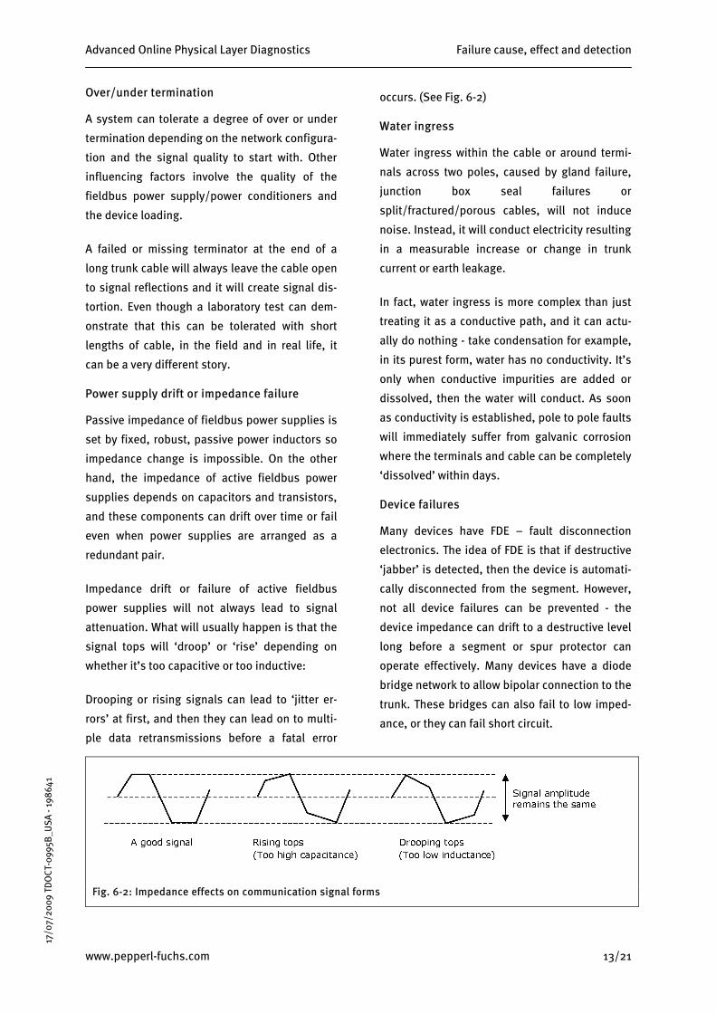
Impedance drift or failure of active fieldbus
power supplies will not always lead to signal
attenuation. What will usually happen is that the
signal tops will ‘droop’ or ‘rise’ depending on
whether it’s too capacitive or too inductive:
Drooping or rising signals can lead to ‘jitter er-
rors’ at first, and then they can lead on to multi-
ple data retransmissions before a fatal error
occurs. (See Fig. 6-2)
Water ingress
Water ingress within the cable or around termi-
nals across two poles, caused by gland failure,
junction box seal failures or
split/fractured/porous cables, will not induce
noise. Instead, it will conduct electricity resulting
in a measurable increase or change in trunk
current or earth leakage.
In fact, water ingress is more complex than just
treating it as a conductive path, and it can actu-
ally do nothing - take condensation for example,
in its purest form, water has no conductivity. It’s
only when conductive impurities are added or
dissolved, then the water will conduct. As soon
as conductivity is established, pole to pole faults
will immediately suffer from galvanic corrosion
where the terminals and cable can be completely
‘dissolved’ within days.
Device failures
Many devices have FDE – fault disconnection
electronics. The idea of FDE is that if destructive
‘jabber’ is detected, then the device is automati-
cally disconnected from the segment. However,
not all device failures can be prevented - the
device impedance can drift to a destructive level
long before a segment or spur protector can
operate effectively. Many devices have a diode
bridge network to allow bipolar connection to the
trunk. These bridges can also fail to low imped-
ance, or they can fail short circuit.
OCT
-099
5B_U
SA -
1986
41
www.pepperl-fuchs.com 13/21
17/0
7/20
09 T
D
Fig. 6-2: Impedance effects on communication signal forms

Failure cause, effect and detection Advanced Online Physical Layer Diagnostics
14/21 www.pepperl-fuchs.com
17/0
7/20
09 T
DO
C
Transient voltage suppression (TVS) and surge arrestors
Surge arrestors or transient voltage suppressors
are always utilized within power supplies, spur
protection and devices to prevent high voltage
surges from destroying or damaging sensitive
internal electronic components.
T-09
95B_
USA
- 19
8641
Although surge arrestors or TVS’s (protection
diodes) can prevent many high voltage spikes
from destroying devices or components, they are
in fact a common point of failure themselves. The
TVS, which are connected directly across the
trunk, can drift or leak or they can effectively fail
to short circuit, which is the common failure
mode for such devices. TVS diodes are inactive
under no electrical or thermal stress during nor-
mal operation and so they should last indefi-
nitely. But they can be weakened after a high
voltage surge, and this often results in an in-
crease in current leakage or a problematic im-
pedance change.
Device noise filter capacitors
Devices, power supplies and protection circuits
commonly use small capacitors for noise filter-
ing. They are arranged across the poles, and
from pole to shield:
Because there are many devices attached to a
single segment, then the number of failure
points will be proportionally high (12 devices =
36 capacitors). The capacitors can fail open cir-
cuit, short circuit and can drift to a lower capaci-
tance with differing effects, where some can be
destructive or if left unattended, they could lead
to a compound failure.
Signal polarity inversion
Many devices are bipolar, means they can be
connected in any polarity to a fieldbus segment.
However, a few devices, power supplies or re-
peaters are not bi-polar, and they have the po-
tential to be accidentally cross-wired. This will
invert the data signal, which in some cases can
be tolerated by the system, but intercommunica-
tion between devices will fail. If devices during
construction and commissioning are cross wired,
many of the faults would not be picked up until
operation commences.
Power supply health and failure
The fieldbus power output voltage could fall to
unacceptable limits over time. Even with redun-
dant power supplies, the voltages can fall due to
a combination of failures i.e. the OR diode fails
short circuit, and one of the power supply out-
puts falls to a lower voltage, at a low impedance.
For redundant power supplies, any one of the
two power supplies could fail, where a replace-
ment will be required on an urgent basis.
Fig. 6-3: Noise filter arrangement

Advanced Online Physical Layer Diagnostics Failure cause, effect and detection
6.1 Detection of failures by the advanced measurement techniques
Having considered the failure types, it can be seen that a vast range of measurement techniques will be
required if an early warning of any potential failure is to be detected in good time and for extensive fault
detection.
This next section will cover the measurement types and how they are used to assess a fault or more impor-
tantly, a propagating fault:
OCT
-0U
SA64
995B
_ -
198
1
www.pepperl-fuchs.com 15/21
17/0
7/20
09 T
D
TYPE OF FAULT DETECTED FAULT DETECTION DESCRIPTION
Device noise filter and diode bridge DC leakage
TVS DC leakage
Inferred device voltage changes
Water ingress
Terminator DC faults
Device current failures
Pole to Pole DC faults.
These faults can be detected by very small changes in trunk current and incremental current changes over time.
Often, trunk current changes are more detectable than changes in signal level, and it is ideal for the early warning of developing pole to pole water ingress which can lead to rapid galvanic corrosion, onset of terminator capacitor leakage, device filter capacitor or diode bridge leakage, protec-tion diode (TVS) leakage and device current failures or drift.
TVS and device bridge impedance change
Active power supply drift or impedance fail-ure,
Under/over termination
Pole to Pole AC faults.
Jitter measurement is by far the most important measurement to make for any propagating AC fault detection.
Jitter measurement ignores specific or discrete failures like noise level or signal attenuation; instead it concentrates on communication data detec-tion accuracy.
It can detect a multitude of changes caused by network impedance varia-tions, signal distortion, network resonance, active fieldbus power supply impedance drift, terminator capacitor or resistor drift, device filter capaci-tor drift, device impedance faults and full bandwidth noise influences.
Noise influence or signal attenuation/distortion may individually meet the required specification limits, but added together could result in a failure. Jitter measurement ignores specific or discrete failure, instead it concen-trates on the problems of data detection accuracy and how ‘good’ the data is. Should a data signal tend towards failure, jitter detection will pick this up long before a corrupted data retransmission can take place.
General attenuation faults
Device communication level faults
Over/under terminator faults
Signal level measurement can be used to detect attenuation caused by severe active power supply impedance failure or drift, cable attenuation, over/under termination or a device impedance failure.
Fieldbus will still operate with very low signal levels, but data can fail long before warning that signal levels are falling below acceptable limits. Jitter measurement in combination with signal level measurements, enables targeted trouble shooting diagnosis.
Failure cause, effect and detection Advanced Online Physical Layer Diagnostics
16/21 www.pepperl-fuchs.com
17/0
7/20
09 T
DO
CT-0
995B
_USA
- 19
8641
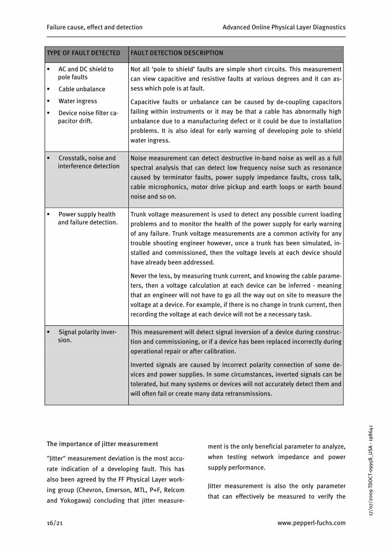
TYPE OF FAULT DETECTED FAULT DETECTION DESCRIPTION
AC and DC shield to pole faults
Cable unbalance
Water ingress
Device noise filter ca-pacitor drift.
Not all ‘pole to shield’ faults are simple short circuits. This measurement can view capacitive and resistive faults at various degrees and it can as-sess which pole is at fault.
Capacitive faults or unbalance can be caused by de-coupling capacitors failing within instruments or it may be that a cable has abnormally high unbalance due to a manufacturing defect or it could be due to installation problems. It is also ideal for early warning of developing pole to shield water ingress.
Crosstalk, noise and interference detection
Noise measurement can detect destructive in-band noise as well as a full spectral analysis that can detect low frequency noise such as resonance caused by terminator faults, power supply impedance faults, cross talk, cable microphonics, motor drive pickup and earth loops or earth bound noise and so on.
Power supply health and failure detection.
Trunk voltage measurement is used to detect any possible current loading problems and to monitor the health of the power supply for early warning of any failure. Trunk voltage measurements are a common activity for any trouble shooting engineer however, once a trunk has been simulated, in-stalled and commissioned, then the voltage levels at each device should have already been addressed.
Never the less, by measuring trunk current, and knowing the cable parame-ters, then a voltage calculation at each device can be inferred - meaning that an engineer will not have to go all the way out on site to measure the voltage at a device. For example, if there is no change in trunk current, then recording the voltage at each device will not be a necessary task.
Signal polarity inver-sion.
This measurement will detect signal inversion of a device during construc-tion and commissioning, or if a device has been replaced incorrectly during operational repair or after calibration.
Inverted signals are caused by incorrect polarity connection of some de-vices and power supplies. In some circumstances, inverted signals can be tolerated, but many systems or devices will not accurately detect them and will often fail or create many data retransmissions.
The importance of jitter measurement
"Jitter" measurement deviation is the most accu-
rate indication of a developing fault. This has
also been agreed by the FF Physical Layer work-
ing group (Chevron, Emerson, MTL, P+F, Relcom
and Yokogawa) concluding that jitter measure-
ment is the only beneficial parameter to analyze,
when testing network impedance and power
supply performance.
Jitter measurement is also the only parameter
that can effectively be measured to verify the

Advanced Online Physical Layer Diagnostics Failure cause, effect and detection
fieldbus power supply’s conformance with
IEC61158-2 and compatibility with other devices.
Passing jitter measurement testing will give the
power supply the standard FF.831 tick mark.
Continued measurement of jitter will also verify
the power supply’s continued compliance with
FF.831 and its operational health.
Jitter analysis will observe small changes that
are not normally significant enough to cause
data retransmissions or any other alarms. Jitter
measurement ignores the singular effects of
noise, attenuation and distortion. For example,
the noise levels may just be within limits and the
signal attenuation and distortion may also just
be within limits so that no alarms are given, but
collectively, they may cause data detection to
fail. Jitter measurement will be able to detect the
onset of failure long before any other measure-
ment parameter is able to react without a false
alarm.
6.2 Deciding which diagnostic hardware/software to chose
Jitter error is caused by signal distortion, noise and network resonance. Jitter errors are basically zero cross-
ing errors where zero crossing is the only measurement that is used to detect the actual 1’s and 0’s of the
data transmission:
Fig. 6-4: Jitter explanation
Deciding which diagnostic module or system to purchase will depend on the needs of the contractor, the
needs of the purchaser and/or operator or even the project scheduling.
The choice should be based on features, performance and cost, although the cost difference is very mar-
ginal between online systems, and the cost must be weighed up against the broader range of savings seen
across the project lifecycle.
In some cases, the control system and associated fieldbus power supplies will not be available during
construction or pre-commissioning and therefore, a portable mobile advanced diagnostic system and ana-
lytical software with portable mobile fieldbus power supplies will be the only option. By ensuring that the
control system, if not, at least the fieldbus power supply hubs fitted with advanced diagnostic equipment,
are installed at an early stage during the project lifecycle, the project would realize significant cost and
time saving benefits.
-099
5B_U
SA -
1986
41
OCT
www.pepperl-fuchs.com 17/21
17/0
7/20
09 T
D
The table below summarizes the differences between the physical layer diagnostic product variants cur-
rently on the market:

Failure cause, effect and detection Advanced Online Physical Layer Diagnostics
Measurement
Mobile advanced diagnos-
tics
Advanced online
diagnos-tics
Handheld fieldbus testers
Basic online
diagnos-tics
Trending and logging of all measurements over time for early warning of a potential fault. YES YES NO YES (lim-
ited)
Trunk current measurement NO YES NO NO
Jitter measurement YES YES NO NO
Data signal amplitude YES YES YES YES
Shield to pole AC and DC unbalance as a percentage for each pole. YES YES NO NO
Direct pole to pole short circuit YES YES YES YES
Full spectral frequency analysis YES YES NO (some yes)
NO (some yes)
High frequency noise measurement YES YES YES YES
Digital storage oscilloscope YES YES NO NO
Trunk voltage YES YES YES YES
Advanced software analysis and hardcopy printout YES YES NO NO
‘Signal inverted’ warning YES YES NO YES
Segregated diagnostic information bus - operation not affected by any segment failure YES YES YES NO
Draws zero current from the bus YES YES NO NO
No need to track down terminals or interfere with cable systems or junction boxes NO YES NO YES
Simultaneous monitoring of all segments. NO YES NO YES
‘Leave in place’ transition from construction through to operation NO YES NO YES
The choice
From the above table, it can clearly bee seen that advanced online diagnostic option will offer the best
overall performance, features and assistance with superior early warning, reporting and application across
the project lifecycle, among other powerful and useful differentiators.
-099
5B_U
SA -
1986
41
T
18/21 www.pepperl-fuchs.com
17/0
7/20
09 T
DO
C

Advanced Online Physical Layer Diagnostics CAPEX & OPEX Savings
7 CAPEX & OPEX Savings Using advanced online or mobile physical layer diagnostics
Fieldbus is still relatively new, and the ‘manning’
levels required for construction, commissioning
and operation of a fieldbus plant is often sized
according to the equivalent 4-20 mA system. This
next section will demonstrate the time and/or
manpower savings seen with not only fieldbus
technology, when compared to 4-20 mA technol-
ogy, but more significantly, the savings seen
when using advanced physical layer diagnostics.
Notes and estimates
This case study will consider:
OCT
-099
5B_U
SA -
1986
41
Number of instruments 1,200
Number of segments 100 (12 instruments per segment)
Man day 8 hours
Mean time to repair (MTTR) a fault
4 hours
Every project varies with regard to engineering
staff levels and time schedules. Other factors
such as the process or the product to be manu-
factured and the environment also play an im-
portant part in overall expenditure, so the esti-
mates are general, but they do give an overview
of the vast savings potential.
Some contractors will allow a team up to 30 min-
utes for construction testing, pre-commissioning
checks and repair per instrument loop. The range
seems to vary between 10 minutes per loop (a
check), and up to 2 hours per loop (a check in-
clusive of repair work) depending on the project
definition. For a 4-20 mA system, 30 minutes per
4-20 mA loop will result in over 2 ¼ months
worth of qualified and experienced engineering
based on an 8 hour shift per day, and a full work-
ing week. This case study will consider a shorter
time estimate.
Pre-commissioning can be grouped with con-
struction, but for simplicity, pre-commissioning
is grouped with commissioning where the com-
mon aspect of control loop checking is ignored
as this will be the same for any hardware model.
Instrument failures will in fact be the same for
any model as there are exactly the same num-
bers of instruments for a classic 4-20 mA system
as there will be for a fieldbus system. Based on a
MTBF of 200 years per instrument, for 1,200
instruments, one would anticipate a failure of
6 instruments each year, and with a MTTR of
4 hours, this will occupy 3 days each year for
repair time. Nevertheless, as this will be the
same for all models, it can be ignored for this
case study.
Equally, any repair work of cable or cable sys-
tems will be the same for fieldbus with diagnos-
tics and without diagnostics. The only difference
being downtime – a repair to prevent a fault may
take the same time as a repair to fix a failure,
and therefore, this can be ignored as they will be
the same.
www.pepperl-fuchs.com 19/21
17/0
7/20
09 T
D

CAPEX & OPEX Savings Advanced Online Physical Layer Diagnostics
20/21 www.pepperl-fuchs.com
17/0
7/20
09 T
DO
CT-0
995B
_USA
- 19
8641
MODEL
Task 4-20 mA Fieldbus without
diagnostics Fieldbus with diagnostics
5 minutes per cable
10 minutes per segment Not required
Constructional checks - each cable will be checked for: continuity, pole to pole and each pole to shield isolation and a test sheet completed. Allowing for time to read the drawings and locate the terminals and connect the cable testers.
NOTE: For fieldbus, additional cable resistance and ca-pacitance checks are required. For fieldbus with diagnos-tics, the cable can be checked at the same time as pre-commissioning checks are performed.
1,200 instrument cables: 1,200 x 5 = 6,000 minutes or 12 ½ days
100 segments: 100 x 10 = 1,000 minutes or 2 days
Not required
1% predicted failure = 12, 4-20 mA loops
1% predicted failure = 1, trunk, 12 spurs
Not required Construction failures: anticipated percentage of cable failures and the time taken to repair the fault based on a 4 hour ‘mean time to repair’ (MTTR).
NOTE: Fieldbus has the same number of spur cables as the 4-20 mA model, plus an additional trunk cable. 12 x 4h = 6 days 13 x 4h = 6 ½
days Not required
10 minutes per cable
60 minutes per segment
8 minutes per segment
Pre/commissioning instrument checks
4-20 mA Analogue - each instrument should be tested with a loop calibrator or handheld tester to ensure correct device polarity, operational voltage test and loop current check for both analogue inputs and analogue outputs with a test sheet completed.
Fieldbus - each network should be tested to ensure cor-rect device communication, signal and noise quality, tag number and address validation, power supply voltage test with a test sheet completed.
NOTE: The advanced diagnostic model will test many more physical layer parameters in a shorter time.
1,200 instrument cables: 1,200 x 10 = 12,000 minutes or 25 days
100 segments: 100 x 60 = 6,000 minutes or 12 ½ days
100 segments: 100 x 8 = 800 minutes or 1.6 days
0.5% predicted failure = 6, 4-20 mA loops
0.5% predicted failure =~ 1 seg-ment
1.5% predicted failure =~ 2 segments
Pre/commissioning failure: anticipated failures and the time take to repair the fault based on a 4 hour ‘mean time to repair’ (MTTR)
NOTE: Fieldbus with diagnostics will include the pre-dicted cable failures. 6 x 4h = 3 days 1 x 4h = 1/2 day 2 x 4h = 1 days
15 minutes per cable
60 minutes per segment
8 minutes per segment
Operational maintenance over a 1 year period observ-ing and inspecting every loop/segment for anomalies and to perform regular shutdown repair and maintenance tasks. Often, the maintenance shift will react to failures passed on from the operating crew.
NOTE: For fieldbus, additional communication checks will need to be performed using oscilloscopes and hand held analyzers. The diagnostic system will test many more physical layer parameters.
1,200 x 15 = 18,000 minutes or 37.5 days
100 x 60 = 6,000 minutes or 12 ½ days
100 segments: 100 x 8 = 800 minutes or 1.6 days
Construction and commissioning times in man-days 46.5 man-days 21.5 man-days 2.6 man-days
Operational maintenance times in man-days 37.5 man-days 12.5 man-days 1.6 man-days
Advanced Online Physical Layer Diagnostics Conclusion and summary
Savings summary
In summary, fieldbus, with its automatic device
commissioning and reduced cable infrastructure,
will reduce the amount of time taken for con-
struction, commissioning and operation testing
and maintenance. Fieldbus with online test
equipment will go on to reduce the time even
further to a very significant level if the system is
implemented and operated effectively. An anal-
ogy to support the claims are seen with ATE
(automatic test equipment) when used to repeat-
edly test the same circuit card on a production
line. The testing is extremely fast even though
the circuit cards may have to be manually
loaded. From the fieldbus model, it can be seen
that there are many repeated circuits that are
already connected in place, and therefore, the
time saving benefits can easily be validated.
8 Conclusion and summary Fieldbus has made it truly ‘cost-possible’ to util-
ize advanced automatic online diagnostics for
every single segment during the construction
and commissioning phases, and to retain the
same hardware/software for the operation
phase, where this would not have been feasible
or economic for an equivalent 4-20 mA system.
From the figures and estimates provided in this
paper, it can be seen that the implementation of
online advanced physical layer diagnostics will
pay for itself in a very short timeframe, and will
no doubt pay for itself after the first expected
failure.
Because the online diagnostic modules are per-
manently integrated into the network infrastruc-
ture (‘always to hand’), the time taken to imple-
ment diagnostic troubleshooting, compliance
testing, report generation, maintenance checks
or analysis is significantly reduced.
OCT
-099
5B_U
SA -
1986
41
Online advanced diagnosis, with its greater
breadth of measurements, can provide early
warning of many more propagating failures and
so reduce downtime, which could not be
achieved by using manually operated test
equipment, handheld fieldbus diagnostic test-
ers, or even systems supporting basic online
physical layer diagnostic capability.
The advanced diagnostic fault finding capability
and selective reporting will take a lot of the
guesswork out of the decision making process.
This enables a degree of de-skilling and reduc-
tion in ‘man’ power.
Online advanced diagnostics can reduce the time
and frequency for scheduled maintenance, as
many of the reported propagating faults can be
tolerated or repaired during operation, and rou-
tine checks are actually performed automatically
in real time 24 hours a day, seven days a week.
During construction, commissioning and opera-
tional maintenance, records and proof of test-
ing/checking ensures complete testing, quality
checking and test consistency as well as verified
conformance or continuing conformance with the
fieldbus standards.
The diagnostic data is sent through an autono-
mous data bus and not on a fieldbus segment or
an expensive fieldbus I/O port. This will increase
the data reliability in a cost-effective way.
www.pepperl-fuchs.com 21/21
17/0
7/20
09 T
D
Finally, fieldbus networks with online advanced
physical layer and applications layer diagnos-
tics, attached to a software validated network,
combined with mechanical and electronic protec-
tion will no doubt be extremely reliable when
proactively maintained – even to say that it could
be more reliable than the equivalent 4-20 mA
model. Furthermore, implementing online ad-
vanced diagnostics and reporting, when com-
pared with the alternatives, will result in a sig-
nificant reduction in CAPEX and OPEX.