manual absolute rotary encoders for profinet -...
TRANSCRIPT

R
Absolute Rotary EncodersIntegration into PROFINET
FACTORY AUTOMATION
MANUAL

With regard to the supply of products, the current issue of the following document is ap-plicable: The General Terms of Delivery for Products and Services of the Electrical Indus-
try, published by the Central Association of the Electrical Industry (Zentralverband Elektrotechnik und Elektroindustrie (ZVEI) e.V.) in its most recent version as well as the
supplementary clause: "Expanded reservation of proprietorship"
Absolute Rotary Encoders

Absolute Rotary Encoders
1 Introduction................................................................................. 5
2 Declaration of Conformity.......................................................... 6
2.1 CE Conformity ...................................................................................... 6
3 Safety ........................................................................................... 7
3.1 Symbols Relevant to Safety ................................................................ 7
3.2 Intended Use ........................................................................................ 7
3.3 General Safety Instructions................................................................. 7
4 Introduction................................................................................. 8
4.1 Using This Manual ............................................................................... 8
4.2 Absolute Rotary Encoders .................................................................. 8
4.3 Communication via PROFINET........................................................... 8
4.3.1 General Information on Communication via PROFINET ..................... 8
4.3.2 PROFINET IO Interface ..................................................................... 9
4.3.3 Project Planning Using Device Description ........................................ 9
4.3.4 PROFINET Address and Identifying a Device.................................... 9
5 Installation................................................................................. 10
5.1 Electrical Connection ........................................................................ 10
5.2 LED Indicators.................................................................................... 10
5.3 Instructions for Mechanical and Electrical Installation.................. 11
6 Data Model for the Device Configuration ............................... 14
6.1 Using Encoder Profile V4.0/V4.1....................................................... 14
6.2 Rotary Encoder Classes.................................................................... 14
6.3 Signal List for Cyclic Data Transmission ......................................... 14
6.4 Standard Telegrams and Manufacturer Telegrams......................... 15
6.5 Format of Position Value (G1_XIST1...3).......................................... 17
6.6 Rotary Encoder Control Word 2 (STW2_ENC) ................................ 18
6.7 Rotary Encoder Status Word 2 (ZSW2_ENC) .................................. 18
3
Absolute Rotary Encoders
6.8 Rotary Encoder Control Word 1 (G1_STW) .....................................19
6.9 Rotary Encoder Status Word 1 (G1_ZSW)........................................20
7 Configuration Principle............................................................ 21
7.1 Rotary Encoder Function at a Glance ..............................................21
7.2 Rotary Encoder Functions — Data Links .........................................21
7.3 Parameters for Acyclic Data Transmission ......................................22
7.3.1 Standard Parameters........................................................................ 23
7.3.2 Device Parameters ........................................................................... 23
7.3.3 Manufacturer Parameters ................................................................. 23
7.3.4 Supported Parameters ..................................................................... 23
7.3.5 Rotary Encoder Function Description............................................... 24
8 Configuring the Rotary Encoder Using Step7 ....................... 29
8.1 Introduction.........................................................................................29
8.2 Installing the GSDML File ..................................................................29
8.3 Selecting a Rotary Encoder...............................................................31
8.4 Assigning Device Names and IP Addresses....................................32
8.5 Setting Rotary Encoder Parameters.................................................35
8.6 Configuring Settings for Isochronous Real Time (IRT) ..................39
8.7 Resetting the Rotary Encoder to Factory Settings .........................45
4

Absolute Rotary EncodersIntroduction
20
15
-12
5
1 Introduction
Congratulations
You have chosen a device manufactured by Pepperl+Fuchs. Pepperl+Fuchs develops, produces and distributes electronic sensors and interface modules for the market of automation technology on a worldwide scale.
Symbols used
The following symbols are used in this manual:
Handling instructions
You will find handling instructions beside this symbol
Contact
If you have any questions about the device, its functions, or accessories, please contact us at:
Pepperl+Fuchs GmbHLilienthalstraße 20068307 MannheimTelephone: +49 621 776-4411Fax: +49 621 776-274411E-Mail: [email protected]
Note!
This symbol draws your attention to important information.

20
15
-12
6
Absolute Rotary EncodersDeclaration of Conformity
2 Declaration of Conformity
2.1 CE Conformity
This product was developed and manufactured under observance of the applicable European standards and guidelines.
Note!
A declaration of conformity can be requested from the manufacturer.

Absolute Rotary EncodersSafety
20
15
-12
7
3 Safety
3.1 Symbols Relevant to Safety
3.2 Intended Use
Absolute rotary encoders detect the rotation angle—and, in the case of a multiturn absolute rotary encoder, the revolutions of the rotary encoder shaft—with high precision and resolution. The absolute position value derived from this is provided by the rotary encoder via the PROFINET interface in accordance with the standard from the "PROFIBUS & PROFINET International (PI)" organization. The rotary encoder is to be integrated into a PROFINET network, and should be used only in this way. Typical applications include positioning tasks and length measurement, for example, for cranes, construction machinery, elevators, and packaging machines.
Read through these instructions thoroughly. Familiarize yourself with the device before installing, mounting, or operating.
Always operate the device as described in these instructions to ensure that the device and connected systems function correctly. The protection of operating personnel and plant is only guaranteed if the device is operated in accordance with its intended use.
3.3 General Safety Instructions
Responsibility for planning, assembly, commissioning, operation, maintenance, and dismounting lies with the plant operator.
Installation and commissioning of all devices must be performed by a trained professional only.
User modification and or repair are dangerous and will void the warranty and exclude the manufacturer from any liability. If serious faults occur, stop using the device. Secure the device against inadvertent operation. In the event of repairs, return the device to your local Pepperl+Fuchs representative or sales office.
Danger!
This symbol indicates an imminent danger.
Non-observance will result in personal injury or death.
Warning!
This symbol indicates a possible fault or danger.
Non-observance may cause personal injury or serious property damage.
Caution!
This symbol indicates a possible fault.
Non-observance could interrupt the device and any connected systems and plants, or result in their complete failure.
Note!
Disposal
Electronic waste is hazardous waste. When disposing of the equipment, observe the current
statutory requirements in the respective country of use, as well as local regulations.

20
15
-12
Absolute Rotary EncodersIntroduction
4 Introduction
4.1 Using This Manual
This manual describes how Pepperl+Fuchs absolute rotary encoders equipped with a PROFINET interface are integrated into a PROFINET network.
The manual is valid for the following absolute rotary encoder types:
■ Exx58N-...PN...
■ ENA58IL-...B17
The descriptions for the following topic areas cover all the important aspects for a simple PROFINET integration:
■ Integration into the PROFINET master interface connection
■ Setting the physical parameters
■ Activating PROFINET communication
■ Communicating with the absolute rotary encoder
4.2 Absolute Rotary Encoders
Absolute rotary encoders output a uniquely coded numerical value at each shaft position. Depending on the design type, the measured value is recorded via the optical scanning of a transparent code disc (EVM58...) or via a magnetic sensing principle (ENA58IL...).
The maximum resolution per revolution is 65,536 steps (16 bits). The multiturn version can detect up to 16,384 revolutions (14 bits). As such, the highest possible resolution is 30 bits.
4.3 Communication via PROFINET
4.3.1 General Information on Communication via PROFINET
PROFINET is an open standard for industrial automation based on industrial Ethernet. PROFINET integrates information technology with established standards such as TCP/IP and XML in automation technology.
The communication concept for setting up decentralized applications within PROFINET is PROFINET IO, i.e. decentralized field devices are integrated by PROFINET IO. The familiar IO view of PROFIBUS DP is used where the usable data of the field devices is transferred to the controller process image in cycles. PROFINET IO is a device model consisting of slots and channels, which is based on the main features of PROFIBUS DP. The field device properties are written in a GSDML (generic station description markup language) based on XML. PROFINET IO is engineered in the same way as has long been the case for system integrators of PROFIBUS DP. The decentralized field devices are assigned in the design of a controller.
PROFINET IO draws a distinction between three device types: IO controller, IO device, and IO supervisor.
IO controller: Controller that executes the automation program.
IO device: Decentrally assigned field device that is assigned to an IO controller.
IO supervisor: Programming unit/PC with commissioning and diagnostic functions.
Note!
More information on technical data, mechanical data, pin assignments, and available
connection cables for the relevant absolute rotary encoder types "EVM5 8N-...PN..." and
"ENA58IL-...ProfiNET" can be found in the corresponding datasheet.
8

Absolute Rotary EncodersIntroduction
20
15
-12
4.3.2 PROFINET IO Interface
The absolute rotary encoders are PROFINET IO devices that communicate cyclically with the assigned PROFINET IO controller during operation.
The PROFINET interface of the absolute rotary encoder supports:
■ A transfer rate of 100 Mbit/s
■ The RT (Real Time) and IRT (Isochronous Real Time) real-time categories
■ The range of device functions in accordance with Conformance Class A, B (RT Communication) and Conformance Class C (IRT Communication).
4.3.3 Project Planning Using Device Description
As with PROFIBUS DP, a field device is integrated into the project planning tool by way of a device description. The properties of the field device are described in the device description GSDML (Generic Station Description Markup Language) file. The GSDML file contains the field device data (technical features and information for communication) that you need to operate the device in a PROFINET network. The GSDML file is also referred to as a GSD file in some project planning tools and other informational documents.
The GSDML file is imported into a project planning tool. Peripheral addresses are assigned to the individual channels of the field devices. The peripheral input addresses incorporate the received data. The user program evaluates and processes this data. The user program generates the peripheral output values and sends them to the control interface.
Once project planning is complete, the IO controller receives the planning and configuration data. The IO controller parameterizes and configures the field devices automatically.
Downloading the GSDML
You can find the relevant GSDML file in the Software section of the product detail page for the device.
To access the product detail page for the device, go to http://www.pepperl-fuchs.com and type information about the device (e.g., the product description or the item number) into the search function.
4.3.4 PROFINET Address and Identifying a Device
Every PROFINET IO device has a unique device identification in the PROFINET network. This device identification consists of the following:
■ A unique MAC address. This MAC address is printed on the nameplate of the device.
■ A device name. This must be specified in the project planning software.
■ An IP address. This must be specified in the project planning software. On delivery, the rotary encoder has the IP address "0.0.0.0".
9

20
15
-12
Absolute Rotary EncodersInstallation
5 Installation
5.1 Electrical Connection
The absolute rotary encoder is connected to the field environment via the "Power/PWR" connector along with "Port 1" and "Port 2" for the PROFINET connection.
Connector and pin assignment
5.2 LED Indicators
The absolute rotary encoder features 6 LED indicators for displaying the operating status and diagnostic information in the event of a fault.
The LEDs indicate the following behavior, depending on their function:
■ On
■ Off
■ Flashing
Figure 5.1 LED display with ENA58IL-R*** ProfiNET as an example
Connection
Power/PWR
Connector plug, M12 x 1, 4-pin, A-
coded
Port 1, port 2
Connector socket, M12 x 1, 4-pin, D-
coded
1 Operating voltage +U B Tx +
2 - Rx +
3 0 V Tx-
4 - Rx -
1
3
42
1
3
4 2
10
Absolute Rotary EncodersInstallation
20
15
-12
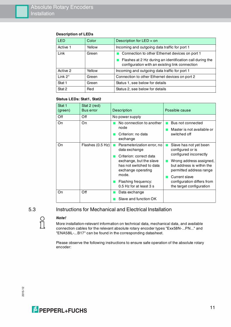
Description of LEDs
Status LEDs: Stat1, Stat2
5.3 Instructions for Mechanical and Electrical Installation
Please observe the following instructions to ensure safe operation of the absolute rotary encoder:
LED Color Description for LED = on
Active 1 Yellow Incoming and outgoing data traffic for port 1
Link Green ■ Connection to other Ethernet devices on port 1
■ Flashes at 2 Hz during an identification call during the
configuration with an existing link connection
Active 2 Yellow Incoming and outgoing data traffic for port 1
Link 2* Green Connection to other Ethernet devices on port 2
Stat 1 Green Status 1, see below for details
Stat 2 Red Status 2, see below for details
Stat 1
(green)
Stat 2 (red)
Bus error Description Possible cause
Off Off No power supply
On On ■ No connection to another
node
■ Criterion: no data
exchange
■ Bus not connected
■ Master is not available or
switched off
On Flashes (0.5 Hz) ■ Parameterization error, no
data exchange
■ Criterion: correct data
exchange, but the slave
has not switched to data
exchange operating
mode.
■ Flashing frequency:
0.5 Hz for at least 3 s
■ Slave has not yet been
configured or is
configured incorrectly
■ Wrong address assigned,
but address is within the
permitted address range
■ Current slave
configuration differs from
the target configuration
On Off ■ Data exchange
■ Slave and function OK
Note!
More installation-relevant information on technical data, mechanical data, and available
connection cables for the relevant absolute rotary encoder types "Exx58N-...PN..." and
"ENA58IL-...B17" can be found in the corresponding datasheet.
11

20
15
-12
Absolute Rotary EncodersInstallation
Warning!
Work must only be performed by trained and qualified personnel.
Commissioning and operation of this electrical equipment must only be performed by trained and qualified personnel. This means individuals who are qualified to commission (in accordance with safety technology), connect to ground, and label devices, systems, and circuits.
Warning!
Only perform work when the system is in a de-energized state.
De-energize your device before performing work on the electrical connections. Short circuits, voltage peaks, and similar events can lead to faults and undefined statuses. This presents a significant risk of personal injury and property damage.
Warning!
Check electrical connections before switching on the plant!
Check all electrical connections before switching on the plant. Incorrect connections present a significant risk of personal injury and property damage. Incorrect connections can lead to failures.
Caution!
Do not remove the rotary encoder housing!
Do not remove the rotary encoder housing under any circumstances, as damage and contamination can occur as a result of taking improper action. It is, however, permitted to remove connector covers.
Caution!
Do not perform any electrical modifications!
It is not permitted to perform electrical modifications on the rotary encoders. If you open or modify the device yourself, not only are you endangering yourself and others but you will void any warranty and absolve the manufacturer from any liability.
Caution!
Ensure that the data cable and power supply cable are physically separate.
Route the connection cable of the rotary encoder so that it is a suitable distance away from power supply cables to avoid faults. Shielded cables must be used to ensure reliable data transmission. A perfect ground connection must also be ensured.
12

Absolute Rotary EncodersInstallation
20
15
-12
Do not allow the rotary encoder to fall or expose it to strong vibrations. The rotary encoder is a precision instrument.
Rotary encoders from Pepperl+Fuchs are robust, however, they should nevertheless be protected against damage from the environment by taking appropriate protective measures. In particular, the devices must not be installed in a location where they could be misused as a handle or climbing aid.
Do not make any alterations to the drive shaft or the housing on the rotary encoder.
Note!
The drive shaft on the rotary encoder must be connected to the drive shaft on the part to be
measured via a suitable coupling. The coupling is required to protect the drive shaft on the
rotary encoder against excessive levels of force, to compensate for shaft offset, and to reduce
the impact of vibrations. Suitable couplings are available as accessories from Pepperl+Fuchs.
13

20
15
-12
Absolute Rotary EncodersData Model for the Device Configuration
6 Data Model for the Device Configuration
6.1 Using Encoder Profile V4.0/V4.1
The current generation of PROFINET rotary encoders are based on encoder profile V4.1 (PNO no. 3.162). This standardization makes it possible to use products that fulfill this specification together or exchange them for compatible products.
The operational functions of rotary encoders are divided into two application classes (class 3 and 4) based on their profile. The figure below provides an overview of the profiles for PROFIBUS and PROFINET in accordance with the standards.
6.2 Rotary Encoder Classes
PROFINET rotary encoders can be configured as class 3 or 4 PROFINET IO devices in accordance with encoder profile V4.1 (PNO no. 3.162). If you configure the rotary encoder as a class 4 device, all functions of the V4.1 measuring devices profile are supported.
6.3 Signal List for Cyclic Data Transmission
The table below lists the standard signals that are used to configure IO data. The signals are described in more detail in the following sections.
Application class Description
3 Isochronous mode is not supported (IRT)Device with "Base Mode Parameter Access" and limited parameterization of the device functionality
4 Isochronous mode is supported (IRT)Device with scaling and preset functions as well as "Base Mode Parameter Access"
14
Absolute Rotary EncodersData Model for the Device Configuration
20
15
-12
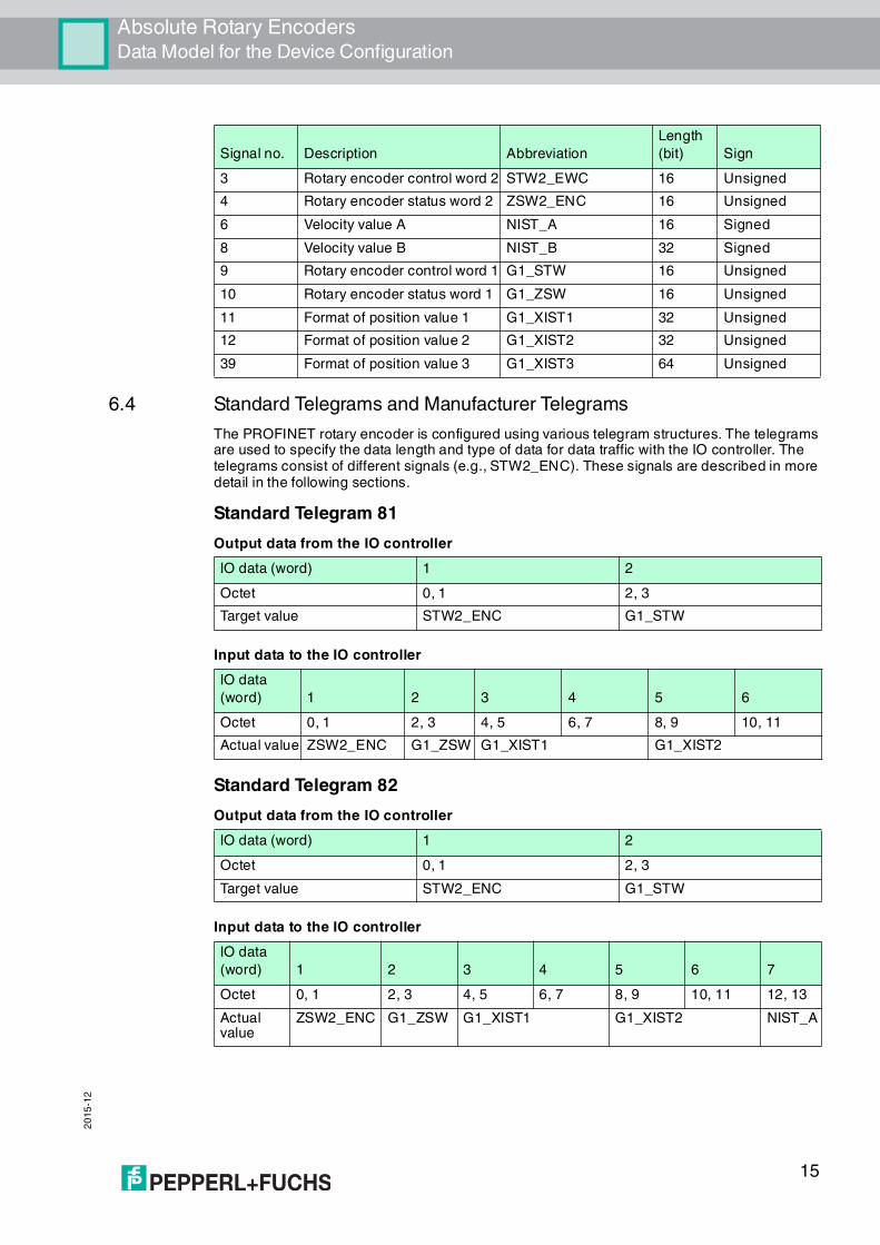
6.4 Standard Telegrams and Manufacturer Telegrams
The PROFINET rotary encoder is configured using various telegram structures. The telegrams are used to specify the data length and type of data for data traffic with the IO controller. The telegrams consist of different signals (e.g., STW2_ENC). These signals are described in more detail in the following sections.
Standard Telegram 81
Output data from the IO controller
Input data to the IO controller
Standard Telegram 82
Output data from the IO controller
Input data to the IO controller
Signal no. Description Abbreviation
Length
(bit) Sign
3 Rotary encoder control word 2 STW2_EWC 16 Unsigned
4 Rotary encoder status word 2 ZSW2_ENC 16 Unsigned
6 Velocity value A NIST_A 16 Signed
8 Velocity value B NIST_B 32 Signed
9 Rotary encoder control word 1 G1_STW 16 Unsigned
10 Rotary encoder status word 1 G1_ZSW 16 Unsigned
11 Format of position value 1 G1_XIST1 32 Unsigned
12 Format of position value 2 G1_XIST2 32 Unsigned
39 Format of position value 3 G1_XIST3 64 Unsigned
IO data (word) 1 2
Octet 0, 1 2, 3
Target value STW2_ENC G1_STW
IO data
(word) 1 2 3 4 5 6
Octet 0, 1 2, 3 4, 5 6, 7 8, 9 10, 11
Actual value ZSW2_ENC G1_ZSW G1_XIST1 G1_XIST2
IO data (word) 1 2
Octet 0, 1 2, 3
Target value STW2_ENC G1_STW
IO data
(word) 1 2 3 4 5 6 7
Octet 0, 1 2, 3 4, 5 6, 7 8, 9 10, 11 12, 13
Actual value
ZSW2_ENC G1_ZSW G1_XIST1 G1_XIST2 NIST_A
15
20
15
-12
Absolute Rotary EncodersData Model for the Device Configuration
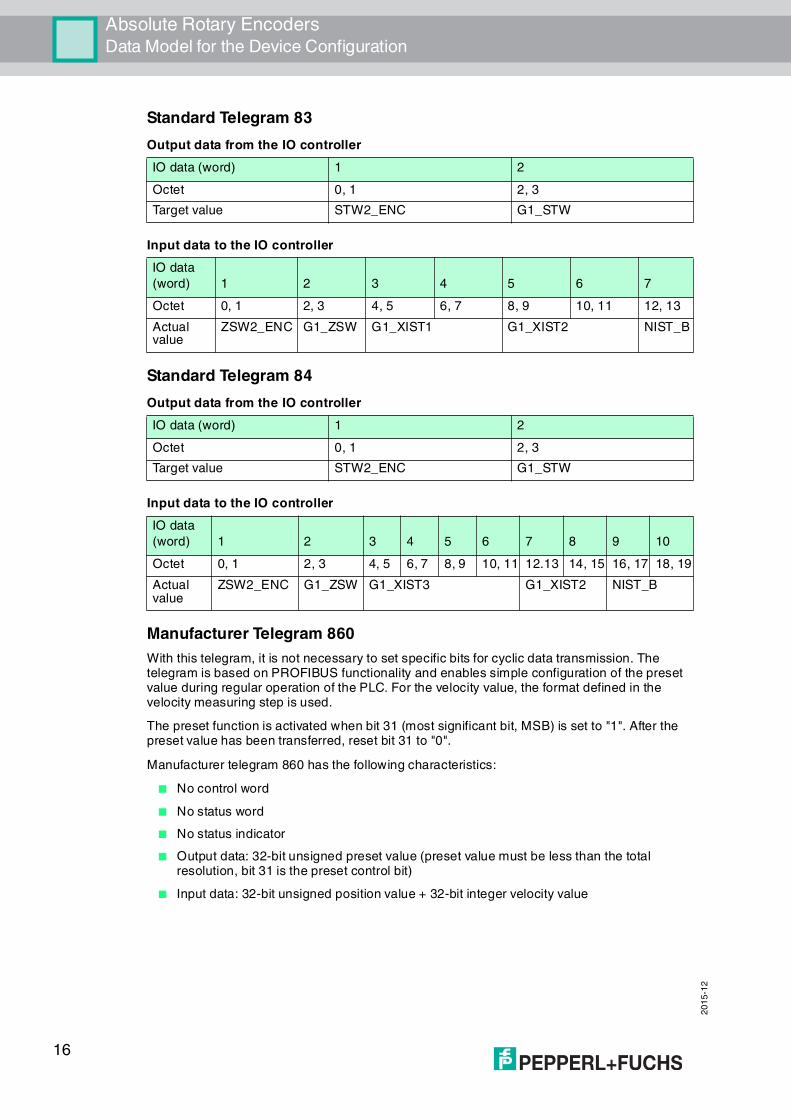
Standard Telegram 83
Output data from the IO controller
Input data to the IO controller
Standard Telegram 84
Output data from the IO controller
Input data to the IO controller
Manufacturer Telegram 860
With this telegram, it is not necessary to set specific bits for cyclic data transmission. The telegram is based on PROFIBUS functionality and enables simple configuration of the preset value during regular operation of the PLC. For the velocity value, the format defined in the velocity measuring step is used.
The preset function is activated when bit 31 (most significant bit, MSB) is set to "1". After the preset value has been transferred, reset bit 31 to "0".
Manufacturer telegram 860 has the following characteristics:
■ No control word
■ No status word
■ No status indicator
■ Output data: 32-bit unsigned preset value (preset value must be less than the total resolution, bit 31 is the preset control bit)
■ Input data: 32-bit unsigned position value + 32-bit integer velocity value
IO data (word) 1 2
Octet 0, 1 2, 3
Target value STW2_ENC G1_STW
IO data
(word) 1 2 3 4 5 6 7
Octet 0, 1 2, 3 4, 5 6, 7 8, 9 10, 11 12, 13
Actual value
ZSW2_ENC G1_ZSW G1_XIST1 G1_XIST2 NIST_B
IO data (word) 1 2
Octet 0, 1 2, 3
Target value STW2_ENC G1_STW
IO data
(word) 1 2 3 4 5 6 7 8 9 10
Octet 0, 1 2, 3 4, 5 6, 7 8, 9 10, 11 12.13 14, 15 16, 17 18, 19
Actual value
ZSW2_ENC G1_ZSW G1_XIST3 G1_XIST2 NIST_B
16

Absolute Rotary EncodersData Model for the Device Configuration
20
15
-12
Output data from the IO controller
Input data to the IO controller
6.5 Format of Position Value (G1_XIST1...3)
The 32-bit signals G1_XIST1 and G2_XIST2 are the output position values in binary format. G1_XIST3 is a 64-bit position value in binary format to support devices with a resolution greater than 32 bits.
The alignment in the data frame (left-aligned or right-aligned) is taken into consideration for each individual resolution. An example for absolute rotary encoders is given below.
Example:
25-bit multiturn absolute rotary encoder (8192 steps per revolution, 4096 revolutions)
■ All values are output in binary format.
■ If an error occurs, G1_XIST2 displays the error telegram instead of the right-aligned position value.
■ The shifting factors in the P979 "Sensor Format" show the current format. P979, subindex 4 (shifting factor for G1_XIST2) = 0.
■ The settings in the rotary encoder parameters affect the position value in both G1_XIST1 and G1_XIST2.
G1_XIST1
■ The default setting for G1_XIST1 is right alignment.
■ A 32-bit counter starts with the current position value. When the maximum numerical value is reached, the counter starts again at 0 and counts up to the maximum numerical value or counts downward from the maximum numerical value to zero.
■ P979, subindex 3 (shifting factor for G1_XIST1) = 0
■ G1_XIST1 transmits values independent of bit 10 in stw2 and bit 13 in g1_stw1.
IO data (word) 1 2
Octet 0 1 2 3
Bit 31 (MSB) 30–24 23–16 15–8 7–0 (LSB)
Description Preset control bit
Preset value < total resolution
IO data (word) 1 2 3 4
Octet 0 (MSB), 1 2, 3 (LSB) 4 (MSB), 5 6, 7 (MSB)
Actual value Position value: 32 bits, unsigned Velocity value: 32 bits, signed
Note!
The alignment of the output format (left-aligned or right-aligned) remains constant and affects
the actual resolution set. The number of transferred bits depends on the resolution.
Bit 31...13 Bit 12...0
MNumber of revolutions (multiturn value)
SSteps (singleturn steps per revolution)
17

20
15
-12
Absolute Rotary EncodersData Model for the Device Configuration
G1_XIST2
G1_XIST3
The G1_XIST3 signal for resolutions greater than 32 bits is transmitted in binary format with right alignment and without a shifting factor.
6.6 Rotary Encoder Control Word 2 (STW2_ENC)
Rotary encoder control word 2 is referred to as the "master sign of life" and is used to control isochronous mode. The status word includes the "Control by PLC" mechanism and the "Controller sign of life" mechanism.
■ 4-bit counter, left-aligned.
■ The master application starts the sign of life counter with any value between 1 and 15. Only values between 1 and 15 are valid for the sign of life counter.
■ The master increases the sign of life counter in every cycle of the master application.
■ "0" indicates an error and is not possible in normal operation.
6.7 Rotary Encoder Status Word 2 (ZSW2_ENC)
Rotary encoder status word 2 is referred to as a "slave sign of life" and is used to control isochronous mode. The status word includes the "Control by PLC" mechanism and the "Slave sign of life" mechanism.
■ 4-bit counter, left-aligned.
■ The slave application starts the sign of life counter with any value between 1 and 15 after successfully synchronizing with the clock pulse. Only values between 1 and 15 are valid for the slave sign of life counter.
■ The sign of life counter is increased by the slave application in every DP cycle.
■ "0" indicates an error and is not possible in normal operation.
Bit 31...25 Bit 24...13 Bit 12...0
MNumber of revolutions (multiturn value)
SSteps (singleturn steps per revolution)
IO data (word) 1 2 3 4
Octet 0, 1 2, 3 4, 5 6, 7
Format 64-bit position value
Bit Function
Implementation
Class 3 Class 4
0 ... 9 Reserved, currently not used
10 Control by PLC Yes Yes
11 Reserved, currently not used
12 ... 15 Controller sign of life Yes
Bit Value Description Note
10 1 Control by PLC Control via interface, EO/IO data is valid
0 No control by PLC EO/IO data is not valid, except sign of life
12 ... 15 Controller sign of life Continuously sends numerical values from 1 � 15
18

Absolute Rotary EncodersData Model for the Device Configuration
20
15
-12
6.8 Rotary Encoder Control Word 1 (G1_STW)
The control word determines the functionality of key rotary encoder functions.
Bit Function
Implementation
Class 3 Class 4
0 ... 8 Reserved, currently not used
9 Control requested Mandatory Mandatory
10, 11 Reserved, currently not used
12 ... 15 Rotary encoder sign of life Mandatory
Bit Value Description Note
9 1 Control requested The automation system is requested to assume control.
0 No control by PLC EO/IO data is not valid, except sign of life
12 ... 15 Rotary encoder sign of life Continuously returns rotary encoder sign of life (numerical values from 1 � 15)
Bit Value Function Note
0 ... 10 Reserved, currently not used
11 0/1 Home position mode Defines whether the position value is set to the previously programmed preset value or whether it is shifted by the preset value.
■ 0: Set home position to preset value
(absolute)
■ 1: Shift home position by preset value
(relative = offset)
12 1 Request to set/shift home position
The home position is set absolutely if bit 12 is changed to "1" (rising edge). Default setting of bit 12 (shift) is 0.Warning! After this function has been triggered, the new offset is stored in nonvolatile memory. During these 5 ms ... 10 ms, the rotary encoder does not send any position values.
13 1 Request absolute value cyclically
Request for additional, cyclic transmission of the absolute current position in G1_XIST2. If no other data needs to be transmitted due to commands or errors, the absolute position value is transmitted automatically.
14 1 Activate "Sensor parking" If the "Sensor parking" bit is activated, the rotary encoder does not send any diagnostic messages or error messages.
15 1 Acknowledge sensor fault Request to acknowledge/reset a sensor fault.
19
20
15
-12
Absolute Rotary EncodersData Model for the Device Configuration
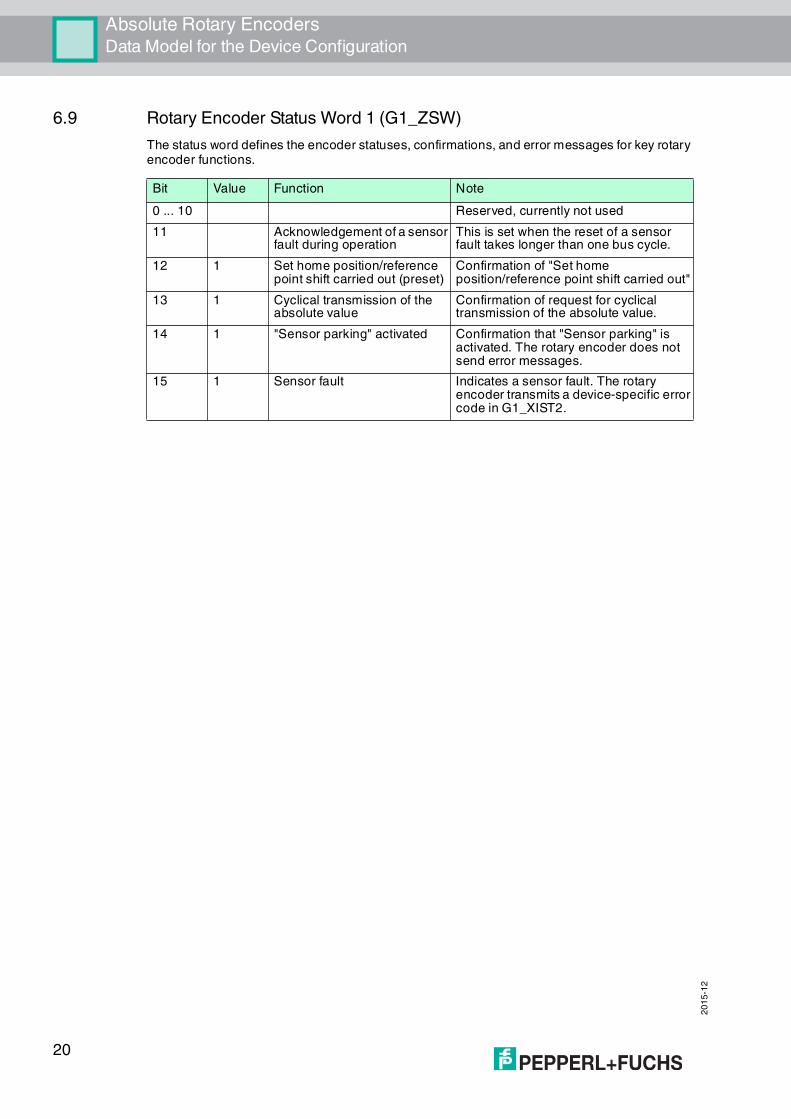
6.9 Rotary Encoder Status Word 1 (G1_ZSW)
The status word defines the encoder statuses, confirmations, and error messages for key rotary encoder functions.
Bit Value Function Note
0 ... 10 Reserved, currently not used
11 Acknowledgement of a sensor fault during operation
This is set when the reset of a sensor fault takes longer than one bus cycle.
12 1 Set home position/reference point shift carried out (preset)
Confirmation of "Set home position/reference point shift carried out"
13 1 Cyclical transmission of the absolute value
Confirmation of request for cyclical transmission of the absolute value.
14 1 "Sensor parking" activated Confirmation that "Sensor parking" is activated. The rotary encoder does not send error messages.
15 1 Sensor fault Indicates a sensor fault. The rotary encoder transmits a device-specific error code in G1_XIST2.
20

Absolute Rotary EncodersConfiguration Principle
20
15
-12
7 Configuration Principle
The absolute rotary encoder for PROFINET can be programmed to meet your specific user requirements. To do this, you must download the appropriate GSDML file from the product detail page for the device from the Pepperl+Fuchs Internet portal and import this into your project planning tool to configure it there.
To access the product detail page for the device, go to http://www.pepperl-fuchs.com and type information about the device (e.g., the product marking or the item number) into the search function. You can find the GSDML file in the Software area of the product detail page.
7.1 Rotary Encoder Function at a Glance
7.2 Rotary Encoder Functions — Data Links
PROFINET IO devices are set up in modules. These modules can be inserted into physical and/or logical slots. The slots are divided into subslots that contain additional information in a hierarchical structure. A subslot can contain several cyclic input/output channels as well as acyclic record channels (required for parameters).
Different controllers (PLCs) are available from different manufacturers. Some PLCs support only one subslot. Others, such as the SIMATIC 400, support multiple subslots. To facilitate operation with all controllers, 2 directories are available in the GSDML file: "Standard" (with PDEV, supports IRT) and "Standard, no PDEV" (does not support IRT).
For older controllers that do not support multiple subslots, Pepperl+Fuchs rotary encoders feature a slot 0 with a subslot 1 for the "Standard, no PDEV" version.
The device parameters are compiled in the PROFINET interface as records. The tables on the following pages provide an overview of the addresses of the data channels of Pepperl+Fuchs rotary encoders.
Function Communication channel
Position value Cyclic input (IO device >> IO controller)
Preset Cyclic output (IO controller >> IO device)
Counting direction Acyclic input/output
Scaling function Acyclic input/output
GSDML file Encoder
PLC project tool PLC
noncyclicaldata transmission(parameters)
cyclicaldata transmission
process data
21
20
15
-12
Absolute Rotary EncodersConfiguration Principle
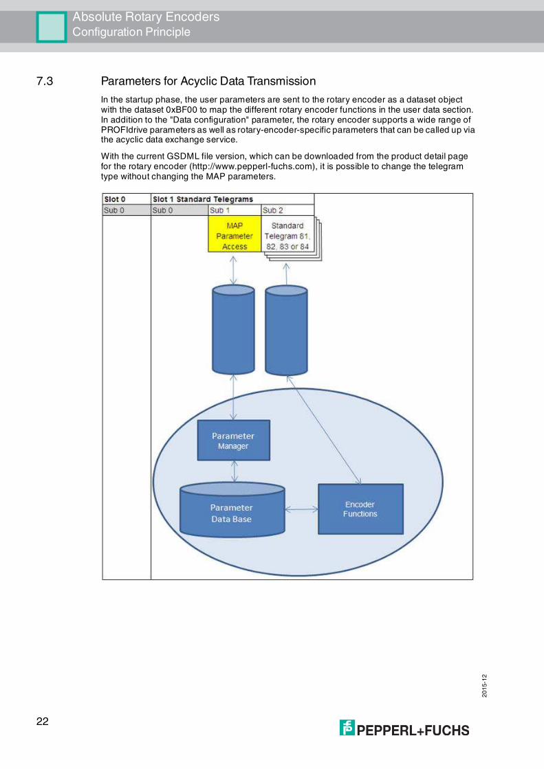
7.3 Parameters for Acyclic Data Transmission
In the startup phase, the user parameters are sent to the rotary encoder as a dataset object with the dataset 0xBF00 to map the different rotary encoder functions in the user data section. In addition to the "Data configuration" parameter, the rotary encoder supports a wide range of PROFIdrive parameters as well as rotary-encoder-specific parameters that can be called up via the acyclic data exchange service.
With the current GSDML file version, which can be downloaded from the product detail page for the rotary encoder (http://www.pepperl-fuchs.com), it is possible to change the telegram type without changing the MAP parameters.
22
Absolute Rotary EncodersConfiguration Principle
20
15
-12
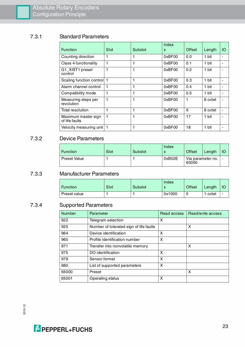
7.3.1 Standard Parameters
7.3.2 Device Parameters
7.3.3 Manufacturer Parameters
7.3.4 Supported Parameters
Function Slot Subslot
Index
x Offset Length IO
Counting direction 1 1 0xBF00 0.0 1 bit -
Class 4 functionality 1 1 0xBF00 0.1 1 bit -
G1_XIST1 preset control
1 1 0xBF00 0.2 1 bit -
Scaling function control 1 1 0xBF00 0.3 1 bit -
Alarm channel control 1 1 0xBF00 0.4 1 bit -
Compatibility mode 1 1 0xBF00 0.5 1 bit -
Measuring steps per revolution
1 1 0xBF00 1 8 octet -
Total resolution 1 1 0xBF00 9 8 octet -
Maximum master sign of life faults
1 1 0xBF00 17 1 bit -
Velocity measuring unit 1 1 0xBF00 18 1 bit -
Function Slot Subslot
Index
x Offset Length IO
Preset Value 1 1 0xB02E Via parameter no. 65000
-
Function Slot Subslot
Index
x Offset Length IO
Preset value 1 1 0x1000 0 1 octet -
Number Parameter Read access Read/write access
922 Telegram selection X
925 Number of tolerated sign of life faults X
964 Device identification X
965 Profile identification number X
971 Transfer into nonvolatile memory X
975 DO identification X
979 Sensor format X
980 List of supported parameters X
65000 Preset X
65001 Operating status X
23

20
15
-12
Absolute Rotary EncodersConfiguration Principle
7.3.5 Rotary Encoder Function Description
The table below provides an overview of the available rotary encoder functions that are enabled or disabled depending on the "Class 4 functionality" setting. Detailed descriptions of these parameters can be found in the following sections.
Counting Direction
The "Code sequence" parameter defines the direction of rotation in which the absolute position value of the rotary encoder shaft should increase. When looking down onto the encoder shaft, the value increases when the shaft is rotating clockwise (CW) or counterclockwise (CCW).
Class 4 Functionality
The "Class 4 functionality" parameter specifies that scaling, preset, and code sequence influence the "Format of position value 1...3" signals G1_XIST1 to G1_XIST3.
Function
Class 4 functionality is
disabled
Class 4 functionality is
enabled
Counting direction – X
Class 4 functionality X
G1_XIST1 preset control – X
Scaling function control – X
Alarm channel control X X
Preset value – X
Preset value (64 bits) – –
Measuring steps per revolution (32 bits)
– X
Total measuring range (32 bits) – X
Measuring steps per revolution (64 bits)
– X
Total measuring range (64 bits) – X
Maximum master sign of life faults – X
Velocity measuring unit X X
Offset value (32 bits) – –
Offset value (64 bits) – X
Rotary axis functionality Always active Always active
Velocity filter X X
Counting direction Direction of rotation Counting direction
922 Clockwise (CW) Increasing
925 Counterclockwise (CCW) Decreasing
Class 4 control Class 4 function
0 (standard) Deactivated (disable)
1 Activated (enable)
24
Absolute Rotary EncodersConfiguration Principle
20
15
-12
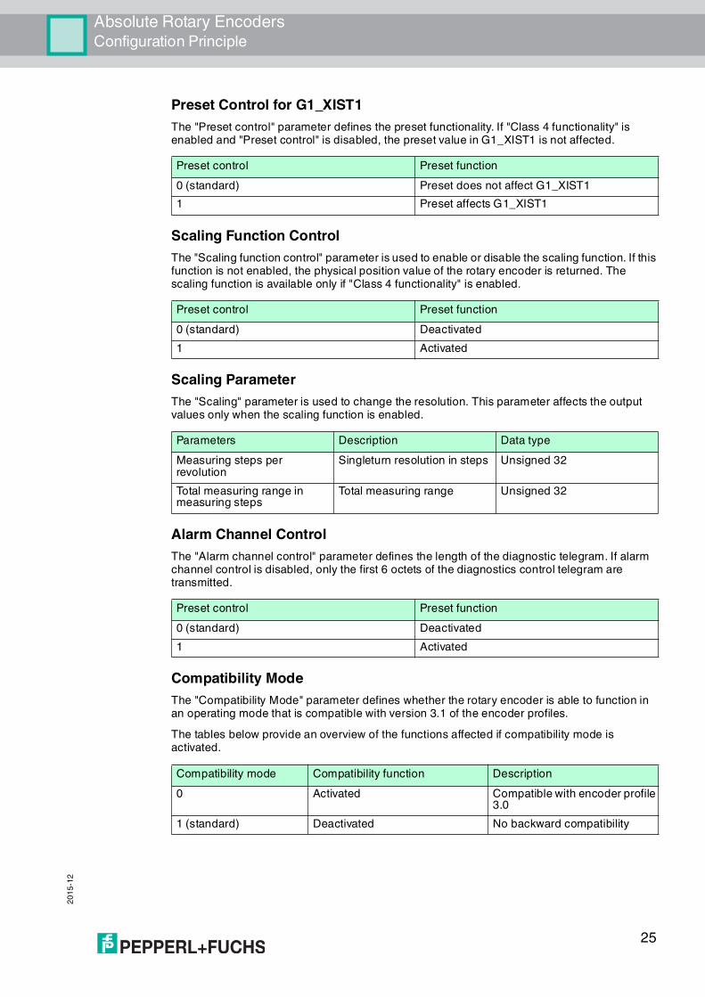
Preset Control for G1_XIST1
The "Preset control" parameter defines the preset functionality. If "Class 4 functionality" is enabled and "Preset control" is disabled, the preset value in G1_XIST1 is not affected.
Scaling Function Control
The "Scaling function control" parameter is used to enable or disable the scaling function. If this function is not enabled, the physical position value of the rotary encoder is returned. The scaling function is available only if "Class 4 functionality" is enabled.
Scaling Parameter
The "Scaling" parameter is used to change the resolution. This parameter affects the output values only when the scaling function is enabled.
Alarm Channel Control
The "Alarm channel control" parameter defines the length of the diagnostic telegram. If alarm channel control is disabled, only the first 6 octets of the diagnostics control telegram are transmitted.
Compatibility Mode
The "Compatibility Mode" parameter defines whether the rotary encoder is able to function in an operating mode that is compatible with version 3.1 of the encoder profiles.
The tables below provide an overview of the functions affected if compatibility mode is activated.
Preset control Preset function
0 (standard) Preset does not affect G1_XIST1
1 Preset affects G1_XIST1
Preset control Preset function
0 (standard) Deactivated
1 Activated
Parameters Description Data type
Measuring steps per revolution
Singleturn resolution in steps Unsigned 32
Total measuring range in measuring steps
Total measuring range Unsigned 32
Preset control Preset function
0 (standard) Deactivated
1 Activated
Compatibility mode Compatibility function Description
0 Activated Compatible with encoder profile 3.0
1 (standard) Deactivated No backward compatibility
25
20
15
-12
Absolute Rotary EncodersConfiguration Principle
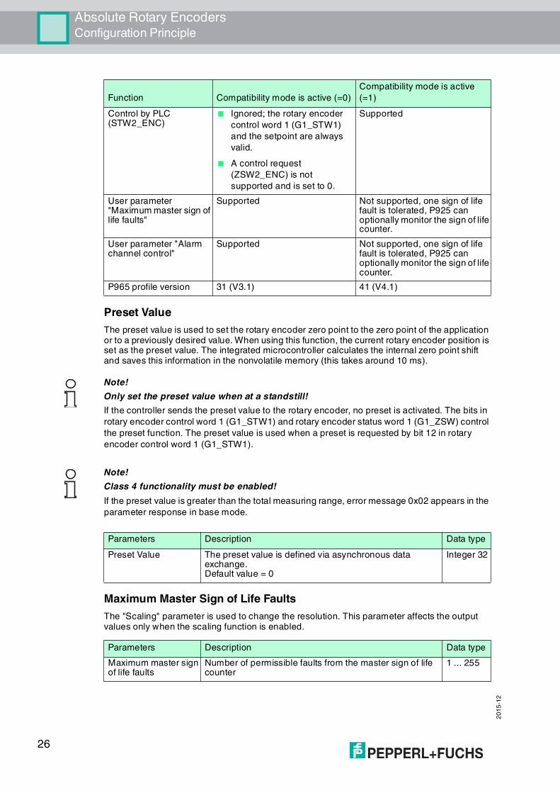
Preset Value
The preset value is used to set the rotary encoder zero point to the zero point of the application or to a previously desired value. When using this function, the current rotary encoder position is set as the preset value. The integrated microcontroller calculates the internal zero point shift and saves this information in the nonvolatile memory (this takes around 10 ms).
Maximum Master Sign of Life Faults
The "Scaling" parameter is used to change the resolution. This parameter affects the output values only when the scaling function is enabled.
Function Compatibility mode is active (=0)
Compatibility mode is active
(=1)
Control by PLC(STW2_ENC)
■ Ignored; the rotary encoder
control word 1 (G1_STW1)
and the setpoint are always
valid.
■ A control request
(ZSW2_ENC) is not
supported and is set to 0.
Supported
User parameter "Maximum master sign of life faults"
Supported Not supported, one sign of life fault is tolerated, P925 can optionally monitor the sign of life counter.
User parameter "Alarm channel control"
Supported Not supported, one sign of life fault is tolerated, P925 can optionally monitor the sign of life counter.
P965 profile version 31 (V3.1) 41 (V4.1)
Note!
Only set the preset value when at a standstill!
If the controller sends the preset value to the rotary encoder, no preset is activated. The bits in
rotary encoder control word 1 (G1_STW1) and rotary encoder status word 1 (G1_ZSW) control
the preset function. The preset value is used when a preset is requested by bit 12 in rotary
encoder control word 1 (G1_STW1).
Note!
Class 4 functionality must be enabled!
If the preset value is greater than the total measuring range, error message 0x02 appears in the
parameter response in base mode.
Parameters Description Data type
Preset Value The preset value is defined via asynchronous data exchange.Default value = 0
Integer 32
Parameters Description Data type
Maximum master sign of life faults
Number of permissible faults from the master sign of life counter
1 ... 255
26

Absolute Rotary EncodersConfiguration Principle
20
15
-12
Velocity Measuring Unit
The "Velocity measuring unit" parameter is used to define the unit that is used to transmit the velocity to telegrams 82, 83, and 84 via signals NIST_A and NIST_B. Telegram 81 contains no velocity values.
The velocity is calculated from the position value with each cycle. A short cycle time is required to achieve a high level of accuracy for the velocity measurement.
Offset Value
The "Offset value" parameter is calculated in the preset function and shifts the position value by the calculated value.
Rotary Axis Functionality
Normally, dividing the "Total measuring range" (as a decimal number) by "Measuring steps per revolution" must result in an integer. The total measuring range must also fit into an integer multiple of 4096 for a rotary encoder with 12 bits per revolution. This means that 100 or 325 revolutions, for example, could result in faults.
Therefore, the following equation must be observed:
(4096 x measuring steps per revolution)/total measuring range = integer value
However, this PROFINET rotary encoder manages this task automatically using an internal software routine, meaning that any deviation from this equation does not result in faults. The rotary encoder checks whether the parameters require rotary axis functionality and then activates this function independently.
Velocity Filter
The velocity value can be set using 3 different filter types that draw on the exponential moving average.
Velocity measuring unit Value
Steps/s 0
Steps/100 ms 1
Steps/10 ms 2
Revolutions per minute 3
Caution!
Operate the rotary encoder with a power supply connected!
The internal software routine is active only when the rotary encoder is connected to the power supply. If it is necessary to turn the rotary encoder shaft by more than 1024 revolutions without a power supply, this can result in faults. This is because the software does not work without a power supply connected. Additional values are stored in the nonvolatile memory with rotary axis functionality. If it is absolutely necessary to rotate the rotary encoder shaft without a power supply, e.g., for service purposes, the equation mentioned above must be observed.
Parameters Description Data type
Velocity filter Parameter selection: fine, normal, coarseThe default setting is "Fine".
Integer 32
Relationship between the old and the current velocity value
Fine: 7:3
Normal: 96:4
Coarse: 996:4
27

20
15
-12
Absolute Rotary EncodersConfiguration Principle
Rotary Encoder Profile Version
The "Rotary encoder profile version" parameter is the version of the rotary encoder profile document used in the rotary encoder. This parameter is not affected by the compatibility mode settings.
Bits Description
0...7 Profile version, least significant bit (LSB), value range 0...99, decimal code
8...15 Profile version, most significant bit (MSB), value range 0...99, decimal code
16...31 Reserved
28
Absolute Rotary EncodersConfiguring the Rotary Encoder Using Step7
20
15
-12
8 Configuring the Rotary Encoder Using Step7
8.1 Introduction
The following pages provide an example of how to configure a Pepperl+Fuchs absolute rotary encoder using the SIMATIC Manager Step7 (Version 5.5 SP4) project planning tool from SIEMENS.
The following hardware components are used:
■ ENA58IL-...B17... absolute rotary encoder (PROFINET)
■ SIMATIC S7-400 CPU 412-1
■ Communication processor CP443-1 as PROFINET IO controller
Steps for Integrating the Rotary Encoder
To ensure correct installation, configuration, and parameterization of the rotary encoder, you must carry out the steps described on the following pages in the specified order:
■ Install the GSDML file
■ Select a rotary encoder
■ Assign a device name and IP address
■ Set the encoder parameters
■ Configure the settings for isochronous real time (IRT communication)
Resetting the Rotary Encoder to Factory Settings
If, for any reason, you wish to reset the rotary encoder settings back to the factory settings, you can find a description of how to do this at the end of the configuration chapter.
8.2 Installing the GSDML File
Downloading the GSDML
You can find the relevant GSDML file in the Software section of the product detail page for the device.
To access the product detail page for the device, go to http://www.pepperl-fuchs.com and type information about the device (e.g., the product description or the item number) into the search function.
1. Download the appropriate GSDML file for your absolute rotary encoder and store this in any directory.
2. Start the SIMATIC Manager
Note!
Before starting configuration with the project planning tool, the relevant GSDML file must be
downloaded from Pepperl+Fuchs and imported into the project planning tool.
Note!
If you want to use more than one rotary encoder in this PROFINET network, you must assign
each rotary encoder with its own name and carry out the steps listed for each rotary encoder
individually.
29

20
15
-12
Absolute Rotary EncodersConfiguring the Rotary Encoder Using Step7
Figure 8.1
3. Select "Options >> Install GSD File..." (1). Proceed through the following relevant menus and install the required GSDML file.
1
30
Absolute Rotary EncodersConfiguring the Rotary Encoder Using Step7
20
15
-12
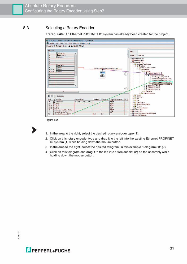
8.3 Selecting a Rotary Encoder
Prerequisite: An Ethernet PROFINET IO system has already been created for the project.
Figure 8.2
1. In the area to the right, select the desired rotary encoder type (1).
2. Click on this rotary encoder type and drag it to the left into the existing Ethernet PROFINET IO system (1) while holding down the mouse button.
3. In the area to the right, select the desired telegram, in this example "Telegram 83" (2).
4. Click on this telegram and drag it to the left into a free subslot (2) on the assembly while holding down the mouse button.
1
2
31
20
15
-12
Absolute Rotary EncodersConfiguring the Rotary Encoder Using Step7
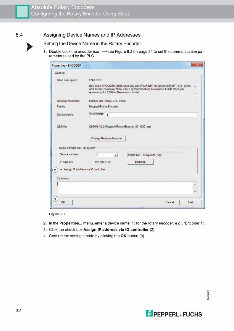
8.4 Assigning Device Names and IP Addresses
Setting the Device Name in the Rotary Encoder
1. Double-click the encoder icon see Figure 8.2 on page 31 to set the communication pa-rameters used by the PLC.
Figure 8.3
2. In the Properties... menu, enter a device name (1) for the rotary encoder: e.g., "Encoder 1".
3. Click the check box Assign IP address via IO controller (2).
4. Confirm the settings made by clicking the OK button (3).
1
2
3
32

Absolute Rotary EncodersConfiguring the Rotary Encoder Using Step7
20
15
-12
Assigning the IP Address and Device Names on the PLC
Prerequisite: The rotary encoder is connected to the PLC via Ethernet and supplied with power.
1. Select "PLC >> Ethernet >>> Assign Device Name..." (1).
Figure 8.4
The system automatically searches the Ethernet network for nodes without an assigned device name. If a rotary encoder is detected, it is displayed in the Assign device name menu under Available devices.
1
33

20
15
-12
Absolute Rotary EncodersConfiguring the Rotary Encoder Using Step7
Figure 8.5
2. Select the rotary encoder (1) and click the Assign name button (2).
3. After successfully assigning the name, exit the menu by clicking Close (3)
Verifying Assignments
The following steps describe how to verify the success of the previously made assignments. You can perform these steps if required.
Select "PLC >> Ethernet >> Verify Device Name..." (1).
Figure 8.6
12
3
1
34

Absolute Rotary EncodersConfiguring the Rotary Encoder Using Step7
20
15
-12
If the rotary encoder is correctly assigned, the device is shown by the SIMATIC Manager with a green tick in the Available devices area.
Figure 8.7
8.5 Setting Rotary Encoder Parameters
Making Changes in the Parameters Menu
1. Double-click the Module Access Point (1) row for the desired rotary encoder.
35

20
15
-12
Absolute Rotary EncodersConfiguring the Rotary Encoder Using Step7
The Properties - Module Access Point menu is displayed.
1
36

Absolute Rotary EncodersConfiguring the Rotary Encoder Using Step7
20
15
-12
Figure 8.8
2. Configure the required parameters, e.g., the code sequence, in the Parameters tab.
37

20
15
-12
Absolute Rotary EncodersConfiguring the Rotary Encoder Using Step7
Figure 8.9
3. Once all parameters have been set, select "Station >> Save and Compile" (1).
Transferring the Project to the Controller
Select "PLC >> Download" (1).
1
38

Absolute Rotary EncodersConfiguring the Rotary Encoder Using Step7
20
15
-12
Figure 8.10
This action transfers all of the information from the rotary encoder to the controller. The rotary encoder is now integrated into SIMATIC Manager and the Ethernet network.
8.6 Configuring Settings for Isochronous Real Time (IRT)
Configuring Object Properties
Prerequisite: As a prerequisite for configuring the following settings, the PROFINET IO controller in use must support the "Sync master" synchronization role with the "high performance" IRT option for isochronous real time (RT class 3).
1. In the table below, click the row with PN-IO (1) to display the menu for configuring the object properties.
1
39
20
15
-12
Absolute Rotary EncodersConfiguring the Rotary Encoder Using Step7
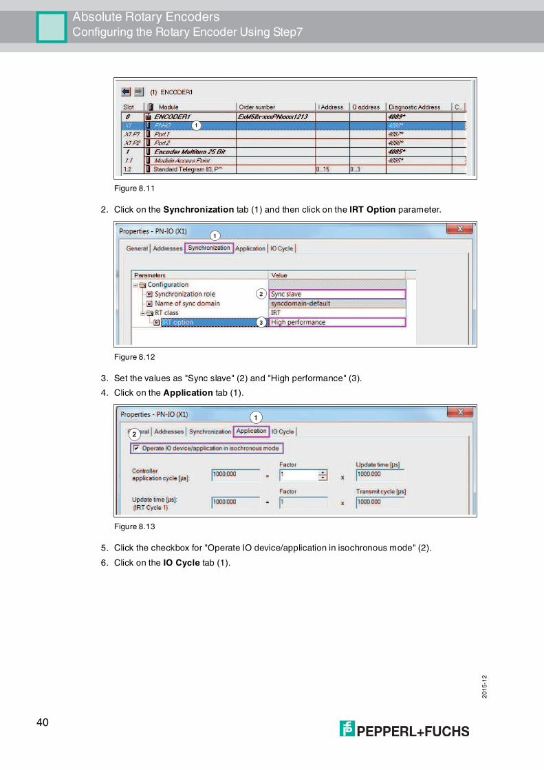
Figure 8.11
2. Click on the Synchronization tab (1) and then click on the IRT Option parameter.
Figure 8.12
3. Set the values as "Sync slave" (2) and "High performance" (3).
4. Click on the Application tab (1).
Figure 8.13
5. Click the checkbox for "Operate IO device/application in isochronous mode" (2).
6. Click on the IO Cycle tab (1).
1
1
2
3
1
2
40

Absolute Rotary EncodersConfiguring the Rotary Encoder Using Step7
20
15
-12
Figure 8.14
7. Set the mode to "Fixed factor" (2).
8. Confirm all settings made by clicking the OK button (3).
Setting Up Ports for the Encoder, IO Controller
1. In the table below, double-click in the row showing Port 1 (1), to set up a port on the rotary encoder for the network connection.
Figure 8.15
2. Click the Topology tab (1) and in the Partners area, enter the partner port displayed in the menu (2).
1
2
3
1
41

20
15
-12
Absolute Rotary EncodersConfiguring the Rotary Encoder Using Step7
Figure 8.16
3. Confirm all settings made by clicking the OK button (3).
Checking the Configuration for IRT Communication
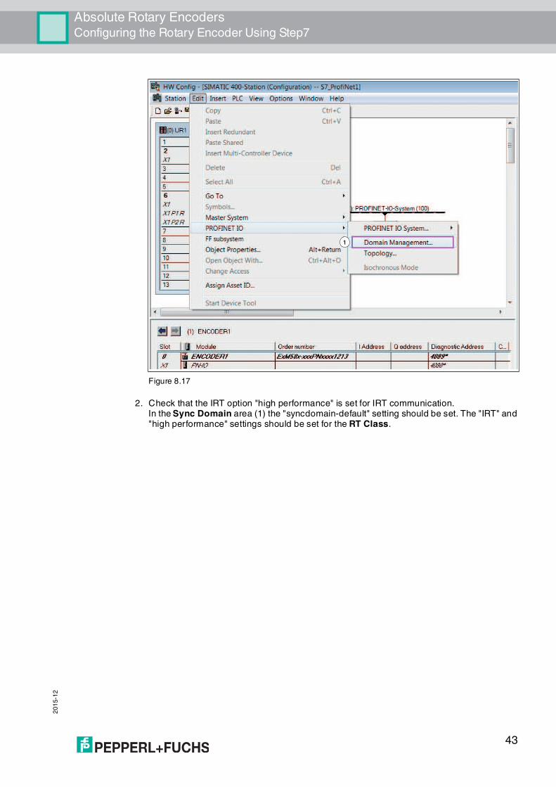
1. Select "Edit >> PROFINET IO >> Domain Management..." (1).
1
2
42
Absolute Rotary EncodersConfiguring the Rotary Encoder Using Step7
20
15
-12
Figure 8.17
2. Check that the IRT option "high performance" is set for IRT communication.In the Sync Domain area (1) the "syncdomain-default" setting should be set. The "IRT" and "high performance" settings should be set for the RT Class.
1
43

20
15
-12
Absolute Rotary EncodersConfiguring the Rotary Encoder Using Step7
Figure 8.18
If the settings detailed above are displayed, the Pepperl+Fuchs PROFINET absolute rotary encoder is parameterized for IRT operation.
1
2
Note!
The rotary encoder has now been properly installed in the project, configured, and
parameterized and is ready for operation in the system.
44

Absolute Rotary EncodersConfiguring the Rotary Encoder Using Step7
20
15
-12
8.7 Resetting the Rotary Encoder to Factory Settings
1. Select "PLC >> Ethernet >> Edit Ethernet Node (1).
Figure 8.19
2. Click the Browse button (1).
Figure 8.20
The SIMATIC Manager searches the Ethernet network for the current nodes. These nodes are then displayed in the Browse Network x Nodes menu.
1
1
45

20
15
-12
Absolute Rotary EncodersConfiguring the Rotary Encoder Using Step7
Figure 8.21
3. Select the rotary encoder (1).
4. If you have installed multiple rotary encoders in the Ethernet network, you can make the LEDs on the relevant rotary encoder flash briefly to aid identification. To do this, click the Flash button (2).
5. Confirm the rotary encoder selection by clicking the OK button (3).
6. Click the Reset button (1).
1
3
2
46

Absolute Rotary EncodersConfiguring the Rotary Encoder Using Step7
20
15
-12
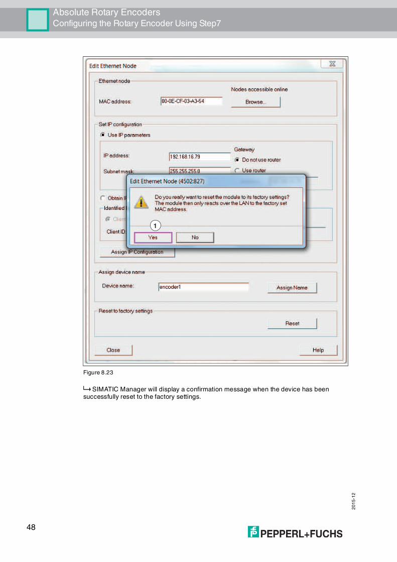
Figure 8.22
7. Confirm the security prompt by clicking Yes (1). Keep in mind that you can now only communicate with the rotary encoder via the network using the MAC address.
1
47
20
15
-12
Absolute Rotary EncodersConfiguring the Rotary Encoder Using Step7
Figure 8.23
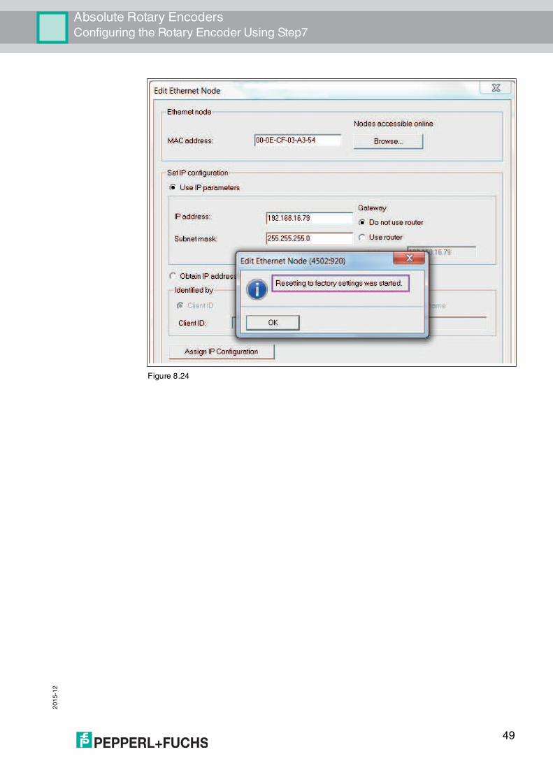
SIMATIC Manager will display a confirmation message when the device has been successfully reset to the factory settings.
1
48
Absolute Rotary EncodersConfiguring the Rotary Encoder Using Step7
20
15
-12
Figure 8.24
49

Subject to modifications Copyright PEPPERL+FUCHS • Printed in Germany
www.pepperl-fuchs.com
FACTORY AUTOMATION – SENSING YOUR NEEDS
Worldwide HeadquartersPepperl+Fuchs GmbH68307 Mannheim · GermanyTel. +49 621 776-0E-mail: [email protected]
USA HeadquartersPepperl+Fuchs Inc.Twinsburg, Ohio 44087 · USATel. +1 330 4253555E-mail: [email protected]
Asia Pacific HeadquartersPepperl+Fuchs Pte Ltd.Company Registration No. 199003130ESingapore 139942Tel. +65 67799091E-mail: [email protected]
/ TDOCT-1213DENG
12/2015