manual fieldbus power hub invensys -...
TRANSCRIPT

FIELDBUS POWER HUB INVENSYSAdvanced high performance power supplies and conditioner
PROCESS AUTOMATION
MANUAL

With regard to the supply of products, the current issue of the following document is applicable: The General Terms of Delivery for Products and Services of the Electrical Industry, published by the
Central Association of the Electrical Industry (Zentralverband Elektrotechnik und Elektroindustrie (ZVEI) e.V.) in its most recent version as well as the supplementary clause: "Expanded reservation
of proprietorship"
FIELDBUS POWER HUB INVENSYS

FIELDBUS POWER HUB INVENSYSContents
1843
07 20
11-0
6
1
1 Safety................................................................................... 31.1 Validity ..........................................................................................................31.2 Symbols used ...............................................................................................31.3 System Operator and Personnel ...................................................................31.4 Pertinent Laws, Standards, Directives, and further Documentation ...............41.5 Delivery, Transport and Storage ....................................................................41.6 Marking.........................................................................................................41.7 Intended use .................................................................................................51.8 Mounting and installation ..............................................................................5
1.8.1 Mounting instructions for motherboards ...................................................51.8.2 Mounting instructions for HD2* modules ..................................................51.8.3 Zone 2 ......................................................................................................61.8.4 Ex nL ........................................................................................................6
1.9 Housing ........................................................................................................61.10 Repair and Maintenance...............................................................................61.11 Disposal ........................................................................................................6
2 Specification ....................................................................... 72.1 Overview.......................................................................................................72.2 System Components.....................................................................................7
2.2.1 Motherboards...........................................................................................72.2.2 Modules ...................................................................................................8
2.3 Component Identity FBTA-228-BPFB*..........................................................92.4 Technical Data ............................................................................................102.5 Dimensional Drawings ................................................................................13
3 Installation and Commissioning ..................................... 143.1 Mounting and Dismounting .........................................................................143.2 Shield and Ground Connection...................................................................153.3 Connections................................................................................................163.4 Segment Termination ..................................................................................173.5 Addressing and ID Switch Settings .............................................................17
3.5.1 Addressing of Motherboards ..................................................................18
4 Fieldbus Power Hub Basic Diagnostics ......................... 195 Thermal Dissipation ......................................................... 21

1843
07 20
11-0
6
2
FIELDBUS POWER HUB INVENSYSContents
6 Appendix........................................................................... 246.1 Ordering Information .................................................................................. 246.2 Electromagnetic Compatibility Verification in Accordance with EC Council
Legislation Directive 2004/108/EC246.3 Referenced Documents.............................................................................. 25
FIELDBUS POWER HUB INVENSYSSafety
1843
07 20
11-0
6
3
1 Safety1.1 Validity
Specific process and instructions in this document require special precautions to guarantee the safety of personnel.
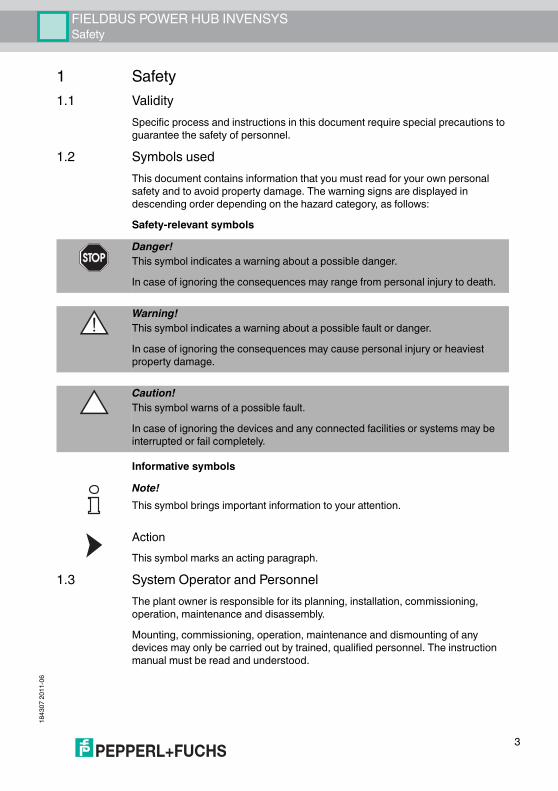
1.2 Symbols usedThis document contains information that you must read for your own personal safety and to avoid property damage. The warning signs are displayed in descending order depending on the hazard category, as follows:Safety-relevant symbols
Informative symbols
ActionThis symbol marks an acting paragraph.
1.3 System Operator and PersonnelThe plant owner is responsible for its planning, installation, commissioning, operation, maintenance and disassembly.Mounting, commissioning, operation, maintenance and dismounting of any devices may only be carried out by trained, qualified personnel. The instruction manual must be read and understood.
Danger!This symbol indicates a warning about a possible danger. In case of ignoring the consequences may range from personal injury to death.
Warning!This symbol indicates a warning about a possible fault or danger.In case of ignoring the consequences may cause personal injury or heaviest property damage.
Caution!This symbol warns of a possible fault.In case of ignoring the devices and any connected facilities or systems may be interrupted or fail completely.
Note!This symbol brings important information to your attention.

1843
07 20
11-0
6
4
FIELDBUS POWER HUB INVENSYSSafety
1.4 Pertinent Laws, Standards, Directives, and further DocumentationLaws, standards, or directives applicable to the intended use must be observed. In relation to hazardous areas, Directive 1999/92/EC must be observed.The corresponding data sheets, declarations of conformity, EC Type-examination certificates, certificates and Control Drawings if applicable (see data sheet) are an integral part of this document. You can find this information under www.pepperl-fuchs.com.
1.5 Delivery, Transport and StorageCheck the packaging and contents for damage. Check if you have received every item and if the items received are the ones you ordered.Keep the original packaging. Always store and transport the device in the original packaging.Always store the device in a clean and dry environment. The permitted storage temperature (see data sheet) must be considered.
1.6 MarkingMotherboards
Power Supply Modules
FBTA-228-BPFB-*Pepperl+Fuchs GmbHFieldbus Power HubTÜV 05 ATEX 2890 X
II 3 G EEx nA II T4
HD2-FBPS-*.500Pepperl+Fuchs GmbHFieldbus Power HubTÜV 04 ATEX 2500 X
II 3 G Ex nA II T4
HD2-FBPS-1.25.360Pepperl+Fuchs GmbHFieldbus Power Hub

FIELDBUS POWER HUB INVENSYSSafety
1843
07 20
11-0
6
5
1.7 Intended useThe devices are only approved for appropriate and intended use. Ignoring these instructions will void any warranty and absolve the manufacturer from any liability.The device must only be operated in the ambient temperature range and at the relative humidity (non-condensing) specified.Protection of the operating personnel and the overall system is not ensured if the product is not being used according to its intended purpose.Fieldbus Power Hub INVENSYSThe Fieldbus Power Hub product range is intended to power fieldbus segments either in simplex or redundant mode according to IEC 61158-2.The solution is intended for use with FOXBORO I/A Series FBM 228 host. The motherboards provide a base for mounting redundant or dual FBM 228 FOUNDATION Fieldbus modules.The FBM modules have to fulfil the requirements for category 3 apparatus and have to be suitable for the conditions at the place of operation (Declaration of the Manufacturer or Certificate of a Testing Department).
1.8 Mounting and installationPrior to mounting, installation, and commissioning of the device you should make yourself familiar with the device and carefully read the instruction manual.
1.8.1 Mounting instructions for motherboardsThe device is designed for installation on a 35 mm DIN mounting rail in accordance with DIN EN 60715.
1.8.2 Mounting instructions for HD2* modulesThe modules are intended for mounting on an appropriate Fieldbus Power Hub motherboard.Instruction for redundant systemsEach segment on a redundant motherboard must only be fitted with two power modules of the same type.
TÜV 06 ATEX 553229 X
II 3 G Ex nA II T4
HD2-FBPS-1.25.360

1843
07 20
11-0
6
6
FIELDBUS POWER HUB INVENSYSSafety
1.8.3 Zone 2If devices have already been operated in general electrical systems, they may subsequently no longer be installed in electrical systems used in combination with hazardous areas.The connection and disconnection of non-power-limited circuits carrying current is permitted only during installation or maintenance, or for purposes of repair.
1.8.4 Ex nLCircuits of type of protection " Ex nL" (limited energy) that are operated with circuits of other type of protections must not be used as "Ex nL" circuits afterwards.
1.9 HousingIf additional housings are needed for installation in hazardous areas, the following points must be considered / evaluated:
■ Degree of protection as per IEC/EN 60529■ Light resistance as per IEC/EN 60079-0■ Impact strength as per IEC/EN 60079-0■ Chemical resistance as per IEC/EN 60079-0■ Heat resistance as per IEC/EN 60079-0■ Electrostatics as per IEC/EN 60079-0
To ensure the IP degree of protection:■ all seals must be undamaged and correctly fitted■ all screws of the housing / housing cover must be tightened with the
appropriate torque■ only cable of the appropriate size must be used in the cable glands■ all cable glands must be tightened with the appropriate torque■ all empty cable glands must be sealed with sealing plugs
1.10 Repair and MaintenanceThe devices must not be repaired, changed or manipulated. If there is a defect, the product must always be replaced with an original device.
1.11 DisposalDisposing of devices, packaging material, and possibly contained batteries must be in compliance with the applicable laws and guidelines of the respective country.

FIELDBUS POWER HUB INVENSYSSpecification
1843
07 20
11-0
6
7
2 Specification2.1 Overview
The FieldConnex Power Hub is a high performance power supply for FOUNDATION Fieldbus. It consists of a motherboard with sockets for plug-in modules and one or two power modules (redundant configuration) per segment. The Power Hub is designed for use with fieldbus systems in accordance with IEC 61158-2. This standard specifies how power and communication are transmitted sharing one shielded twisted-pair cable. Communication between field devices and host system is established by modulating the data signal onto the power stream utilizing Manchester Bus Powered (MBP) transmission.All active electronic components are located in the plug-in modules. Each module holds the electronic components for only one segment and two modules build a redundant configuration. If required, only the smallest amount of electronic components needs to be exchanged. Modules can be exchanged while the system is energized without the use of tools, thus ensuring very high system availability.The Power Hub feeds fieldbus segments following the High-Power Trunk concept for explosion protection. High energy level on the trunk line is fed to the field instrument via couplers as FieldBarriers or Segment Protectors.Using Segment Protectors allows you to do live maintenance at the field device in Zone 2 as outputs are classified Ex nL. Using FieldBarriers allows to do live maintenance in Zone 1 as outputs are classified Ex ia. Thus, limitations for explosion protection are overcome enabling maximum cable lengths and highest number of devices in any explosive area.
2.2 System Components2.2.1 Motherboards
Motherboards are available in redundant or single configuration, for a different number of fieldbus segments. Motherboards are typically mounted on DIN rails inside a wiring or marshalling cabinet. Wiring connectors exist on board for two independent bulk power supplies, fieldbus segments, fault and diagnostics signalling.All motherboards contain the unique, patented CREST technology thereby creating high impedance for common mode noise and network resonance effects.FBTA-228-BPFB-R-4RThe motherboard is designed for use with INVENSYS FBM 228 FOUNDATION Fieldbus modules and allows the redundant supply of four fieldbus segments. Eight sockets will hold the power supply modules, two each are in redundancy per segment.FBTA-228-BPFB-8The motherboard is designed for use with INVENSYS FBM 228 FOUNDATION Fieldbus modules and allows the supply of eight fieldbus segments. Eight sockets will hold the power supply modules.

1843
07 20
11-0
6
8
FIELDBUS POWER HUB INVENSYSSpecification
2.2.2 ModulesPower Modules are connected to the motherboards via sockets. Replacement under live conditions (hot-swap) and load sharing capability in redundant configuration enable uninterruptible communication. The modules are available in different explosion protection configurations and with various isolation levels.
■ Power Supply ModulesModules providing full galvanic isolation between bulk power supply and fieldbus segments are called "Power Supply Modules". They provide optimal system reliability for applications where cabling and wiring are routed through critical or harsh electrical environments, i.e. where superior protection from electromagnetic interference (EMI) is mandatory. Different Power Supply Modules exist with voltage regulated and limited energy levels according to the specifications of FNICO, Entity and FISCO standards. A maximum output current of 500 mA is available to power field devices.
■ Power Conditioner ModulesModules with current limiting circuits between bulk power supply and fieldbus segment and without galvanic isolation are called "Power Conditioner Modules". Power Conditioner Modules carry passive components only and can be used if good wiring practice is followed and reduced safety requirements exist, such as protection type n or increased safety. Power Conditioner Modules utilize CREST technology creating high impedance for common mode noise reduction and network resonance suppression.

FIELDBUS POWER HUB INVENSYSSpecification
1843
07 20
11-0
6
9
2.3 Component Identity FBTA-228-BPFB*
1 Primary power connection2 Secondary power connection3 FBM 14 FBM 25 Fault output6 Screen/ground connection clamp7 ID DIP switch array8 DIN rail slot9 Ethernet trunk Fieldbus connection10 Segment trunk connections11 Shield/ground connection clamp12 Power Module

1843
07 20
11-0
6
10
FIELDBUS POWER HUB INVENSYSSpecification
2.4 Technical DataSystem SpecificationAmbient conditions Ambient temperature -40 ... 60 °C Storage temperature -40 ... 85 °C Shock resistance 15 g , 11 ms Vibration resistance 1 g , 10 ... 150 Hz Relative humidity < 95 % non-condensing Mechanical specifications Connection type screw terminals Core cross-section 2.5 mm2
Protection degree IP20 Standard conformity Electromagnetic compatibility NE 21:2006 Protection degree IEC 60529 Fieldbus standard IEC 61158-2 Shock resistance EN 60068-2-27 Vibration resistance EN 60068-2-6
Motherboard Types MFBTA-BPFB-R*Supply Rated voltage 21.6 ... 25.2 V Rated current 16 A Terminating resistor fixed build in
Isolated Power Supply Module Type HD2-FBPS-1.25.360Supply Rated voltage 19.2 ... 35 V DC Power loss typ. 2 W Fieldbus interface Rated voltage 25 ... 28 V Rated current 360 ... 10 mA Short-circuit current typ. 400 mA Indicators/operating means LED ERR red flashing: short-circuit or undervoltage
at output LED PWR Power LED: green, if Uout > 25 V

FIELDBUS POWER HUB INVENSYSSpecification
1843
07 20
11-0
6
11
Isolated Power Supply Module Type HD2-FBPS-1.500SupplyRated voltage 19.2 ... 35 V DC Power loss typ. 1.8 W Fieldbus interfaceRated voltage 28 ... 30 VRated current 500 ... 10 mA Short-circuit current 550 mA Indicators/operating meansLED ERR red flashing: short-circuit or undervoltage
at outputLED PWR green if Uout > 28 V
Isolated Power Supply Module Type HD2-FBPS-1.23.500Supply Rated voltage 19.2 ... 35 V DC Power loss typ. 1.5 W Fieldbus interface Rated voltage 21 ... 23 V Rated current 500 ... 10 mA Short-circuit current 550 mA Indicators/operating means LED ERR red flashing: short-circuit or undervoltage
at output LED PWR green if Uout > 21 V
Isolated Power Supply Module Type HD2-FBPS-1.17.500Supply Rated voltage 19.2 ... 35 V DC Power loss typ. 1.3 W Fieldbus interface Rated voltage 15 ... 17 V Rated current 500 ... 10 mA Short-circuit current 550 mA Indicators/operating means LED ERR red flashing: short-circuit or undervoltage
at output LED PWR green if Uout > 15 V

1843
07 20
11-0
6
12
FIELDBUS POWER HUB INVENSYSSpecification
Power Conditioner Non-Isolated Type HD2-FBCL-1.500SupplyRated voltage 19.2 ... 35 V DCPower loss typ. 1.3 WFieldbus interfaceRated voltage supply voltage minus max. 2.5 V at full load Rated current 500 ... 10 mAShort-circuit current 600 mAHost-rated current 0 ... 40 mAHost short-circuit current 0 ... 55 mAIndicators/operating meansLED ERR red flashing: short-circuit or undervoltage
at outputLED PWR green if Uout > 16 V

FIELDBUS POWER HUB INVENSYSSpecification
1843
07 20
11-0
6
13
2.5 Dimensional Drawings

1843
07 20
11-0
6
14
FIELDBUS POWER HUB INVENSYSInstallation and Commissioning
3 Installation and Commissioning3.1 Mounting and Dismounting
Mounting of Fieldbus Motherboards on DIN mounting railTo mount a motherboard on a DIN mounting rail, proceed as follows:1. Place the motherboard on the mounting rail.2. Tighten the two fastening screws to attach the motherboard on the DIN rail.
The motherboard has been mounted.Mounting of Modules on the motherboard
To install a new module on the motherboard, proceed as follows:1. Carefully center the polarisation holes and mate the two connectors, then gen-
tly press down the module.2. Push down the red Quick Lok Bars on each side of the module to fix it to the
panel (no tools required).
Caution!Hardware DamageThere is a special connection slot for the diagnostic modules HD2-DM* on the Power Hub motherboard, which is labeled “Diagnostic Module only“. Do not try to plug other modules into this connection slot. Other modules may be damaged.
FIELDBUS POWER HUB INVENSYSInstallation and Commissioning
1843
07 20
11-0
6
15
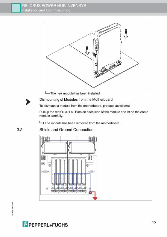
The new module has been installed.Dismounting of Modules from the MotherboardTo dismount a module from the motherboard, proceed as follows:Pull up the red Quick Lok Bars on each side of the module and lift off the entire module carefully.
The module has been removed from the motherboard.3.2 Shield and Ground Connection
1 2 3 4 5
FaultFBM 1FBM 2
Pri Sec
Pow
er
Pri Sec
Pow
er
+ - S
SEG1
+ - S
SEG2
+ - S
SEG3
+ - S
SEG4
+ - S
SEG5
+ - S
SEG6
+ - S
SEG7
+ - S
SEG8

1843
07 20
11-0
6
16
FIELDBUS POWER HUB INVENSYSInstallation and Commissioning
Prevent Grounding LoopsYou can leave the shield earthing at the host connecton open, depending on the selected grounding method. If the grounding points of the host and the field devices do not have the same potential, the shield of the motherboard must be left open to prevent a grounding loop.
3.3 Connections
Caution!This is not a safety earth.Under certain conditions, it may be necessary to ground any exposed metal parts to ground.Note that a correct grounding must be guaranteed at all times.
1 Primary bulk power series connection 2 Secondary bulk power series connection3 Primary bulk power connection4 Secondary bulk power connection5 Fault output series connection6 Fieldbus trunk connection
1 2 3 4 5
FaultFBM 1FBM 2
Pri SecP
ower
Pri Sec
Pow
er
+ - S
SEG1
+ - S
SEG2
+ - S
SEG3
+ - S
SEG4
+ - S
SEG5
+ - S
SEG6
+ - S
SEG7
+ - S
SEG8
FaultFBM 1
Pri Sec
Pow
er
+ - S
SEG7
+ - S
SEG8
+ - S+ - S++ - S+ - S+ -+ --+ - S+ - S+ - S- S + - SSS+ - S+ - S- S+++ -+ - S+ SSSS+ SSS
1 4
5
2 3
5 6

FIELDBUS POWER HUB INVENSYSInstallation and Commissioning
1843
07 20
11-0
6
17
3.4 Segment TerminationMotherboards got integrated terminators for each fieldbus segment.
3.5 Addressing and ID Switch SettingsThe addressing of the Fieldbus Power Hub motherboards and the FBM is based on the principle of FOXBORO's baseplates. For further information, please refer to the corresponding INVENSYS/FOXBORO User Guide: "I/A Series – DIN Rail Mounted FBM Subsystem (B0400FA)".For connecting to the Ethernet bus or for traversing relatively large distances, the Fieldbus Power Hub motherboards must be divided into a maximum of four groups, each with a maximum of eight stations. This corresponds to four non-modular baseplates from FOXBORO, each with eight modules of type FBM.Each motherboard has an ID DIP switch array with five switches. You can adjust the number of the group with the first two switches.
The switches 3 to 5 control the adressing of the motherboard within the group. The motherboards can be numbered according to their physical placement in the enclosure, or according to their position in the cable connection schema.Each ID number must be used once only. The Fieldbus segments must be subdivided into groups of no more than eight stations each.
Warning!Motherboard DamageFor series connection of motherboards the current must not exceed a maximum of 16 A.
Caution!Communication ProblemsWrong termination may cause communication problems or a total communication loss.
■ Make sure that there are two terminators activated on each trunk line.■ One terminator should be located on each end of the trunk line.

1843
07 20
11-0
6
18
FIELDBUS POWER HUB INVENSYSInstallation and Commissioning
3.5.1 Addressing of MotherboardsThe addresses 1, 3, 5 and 7 of the motherboard is assigned to the first FBM module, the second FBM automatically contains the next address.
Motherboard ID settings
FBM ID settings
Group ID Switch 1 Switch 20 ON ON1 ON OFF2 OFF ON3 OFF OFF
FBM ID Switch 3 Switch 4 Switch 51 ON ON ON3 ON OFF ON5 OFF ON ON7 OFF OFF ON

FIELDBUS POWER HUB INVENSYSFieldbus Power Hub Basic Diagnostics
1843
07 20
11-0
6
19
4 Fieldbus Power Hub Basic DiagnosticsThe Fieldbus Power Hub System provides integrated self-supervision functionality located within the Power Modules and the Motherboards. The following conditions are monitored:
■ Availability of the bulk power supply■ Output voltage per segment■ Overload or short circuit per segment■ Power Module failure
The status of the Power Hub is indicated via LEDs and a voltage-free contact. Under normal operating conditions the LEDs are green and the voltage-free contact is closed. See the table below for detailed diagnostic information.
Fault Relay Contact Power ModuleA: Supply Under/Over Voltage Detection> 18.5 V DC +/- 4 %< 35.8 V DC +/- 4 %
< 17.5 V DC +/- 4 %> 36.8 V DC +/- 4 %*
B: Power Module compatibility redundant system onlyAll modules have intact redundancy partner
Only one Power Module is fitted to a segment
C: Power Module or load statusPower Module failure
PWR
ERR
PWR
ERR
PWR
ERR
PWR
ERR
PWR
ERR

1843
07 20
11-0
6
20
FIELDBUS POWER HUB INVENSYSFieldbus Power Hub Basic Diagnostics
Output overload or trunk short circuit
All Power Modules fixed and healthy
Fault Relay Contact Power Module
PWR
ERR
PWR
ERR

FIELDBUS POWER HUB INVENSYSThermal Dissipation
1843
07 20
11-0
6
21
5 Thermal DissipationEach Fieldbus Power Supply will dissipate, i. e. lose energy in form of heat. The graphs below illustrate typical power dissipation values in Watts for one segment including motherboard power losses, for given output currents and supply voltages.
Thermal Dissipation of HD2-FBPS-1.500 and HD2-FBCL-1.500
Dis
spat
ion
in [W
]
Segment current in [mA]
Power dissipation in SIMPLEX configuration per segment
Power dissipation in REDUNDANT configuration per segment
Dis
spat
ion
in [W
]
Segment current in [mA]
19.2V
19.2V
19.2V
2.5
1.5
0.5
19.2V
2.5
1.5
0.5
3.5
35V
24V
32V
24V
HD2-FBCL-1.500
HD2-FBPS-1.500
HD2-FBPS-1.500
35V
24V
32V
24V
HD2-FBCL-1.500
3
2
1
0 500100
200 300 400
3
2
1
0 500100
200 300 400

1843
07 20
11-0
6
22
FIELDBUS POWER HUB INVENSYSThermal Dissipation
Thermal Dissipation of HD2-FBPS-1.17.500
24 V
19,2 V
35 V
3
2,5
2
1,5
1
0,5
24 V35 V
Dis
spat
ion
in [W
]
Segment current in [mA]
Power dissipation in SIMPLEX configuration per segment
Power dissipation in REDUNDANT configuration per segment
HD2-FBPS-1.17.500
HD2-FBPS-1.17.500
0 500100
Dis
spat
ion
in [W
]
Segment current in [mA]
200 300 400
3
3,5
2,5
2
1,5
1
0,5
0 500100 200 300 400
19,2 V

FIELDBUS POWER HUB INVENSYSThermal Dissipation
1843
07 20
11-0
6
23
Thermal Dissipation of HD2-FBPS-1.23.500
24 V19,2 V
35 V3
2,5
2
1,5
1
0,5
24 V
35 V
Dis
spat
ion
in [W
]
Segment current in [mA]
Power dissipation in SIMPLEX configuration per segment
Power dissipation in REDUNDANT configuration per segment
HD2-FBPS-1.23.500
HD2-FBPS-1.23.500
0 500100
Dis
spat
ion
in [W
]
Segment current in [mA]
200 300 400
3
3,5
2,5
2
1,5
1
0,5
0 500100 200 300 400
19,2 V

1843
07 20
11-0
6
24
FIELDBUS POWER HUB INVENSYSAppendix
6 Appendix6.1 Ordering Information
6.2 Electromagnetic Compatibility Verification in Accordance with EC Council Legislation Directive 2004/108/ECCompatibility in accordance with EN61326-1:2006 and Namur NE21:2006 recommendation.The electromagnetic compatibility – EMC – requirements applicable for electrical equipment for measurement, control and laboratory use in general are anchored in the European Standard EN 61326. Three different performance criteria are distinguished in this standard:A category A device operates as intended during the test. This device can withstand the immunity tests without any noticeable performance degradations within the specification limits of the manufacturer. A category B device operates as intended after the test. The device shows temporary degradation or loss of function of performance during the test but self-recovers from that state when the exposures are ceased. A category C device has loss of function, may need manual restoration. During the test a temporary loss of function is allowed as long as an operator can restore the device back to operation.The requirements of the association for standard and control and regulations of the German chemical industries, defined in the NE21 recommendation, are partly higher compared to the test levels and failure criteria defined in EN61326-1. For the product qualification, failure criteria and test levels have been selected, representing always the worst case conditions.
Power Hub System Ordering SummaryHD2-FBPS-1.25.360 Isolated Fieldbus Power Supply Module
with 25 ... 28 V DC and 360 mA output.HD2-FBPS-1.500 Isolated Fieldbus Power Supply Module
with 28 ... 30 V DC and 500 mA output.HD2-FBPS-1.23.500 Isolated Fieldbus Power Supply Module
with 21 ... 23 V DC and 500 mA output.HD2-FBPS-1.17.500 Isolated FNICO Power Supply Module with
15 ... 17 V DC and 500 mA output.HD2-FBCL-1.500 Fieldbus Power Conditioner (non-isolated)
Module with load share and host fault isolation (short circuit protection) 500 mA.
FBTA-228-BPFB-8 Motherboard for eight fieldbus segments and two FOXBORO FGM 228 modules in simplex, dual configuration. Redundant bulk power feed.
FBTA-228-BPFB-R-4R Motherboard for four fieldbus segments and two FOXBORO FGM 228 modules redundant configuration. Redundant bulk power feed.

FIELDBUS POWER HUB INVENSYSAppendix
1843
07 20
11-0
6
25
EN61000-4, as a generic standard, defines the test setups for the specific required test for EN61326-1 and NE21.Applied standards:
■ CE-Conformity 2004/108/EC■ EN61000-4, July 2007■ EN61326-1, October 2006■ EN55011, March 2007■ NE21, Mai 2006
Conducted EMC tests:Immunity
6.3 Referenced Documents■ Manual: "Using Pepperl+Fuchs fieldbus equipment in Zone 2 hazardous
area environment" ■ Selection table: Conformity of FieldConnex® Power Hub power modules
and motherboards to Ex ic
Standard Type Test Level CategoryEN 61000-4-2 Electrostatic
discharge, direct contact
6 kV A
Electrostatic discharge, indirect, air
8 kV A
EN 61000-4-3 Electromagnetic field radiated, radio frequency
10 V/m A
EN 61000-4-4 Fast transients burst on signal lines
1 kV A
Fast transients burst on power lines
2 kV A
EN 61000-4-5 Slow transient surge on signal lines
1 kV B
Slow transient surge on shielded lines
2 kV B
EN 61000-4-6 Conducted immunity, radio frequency
10 V A
EN 55011 RF conducted emission
Class A _
RF radiated emission
Class A _

Subject to modificationsCopyright PEPPERL+FUCHS • Printed in Germany
www.pepperl-fuchs.com
Worldwide HeadquartersPepperl+Fuchs GmbH68307 Mannheim · GermanyTel. +49 621 776-0E-mail: [email protected]
For the Pepperl+Fuchs representative closest to you check www.pepperl-fuchs.com/pfcontact
PROCESS AUTOMATION – PROTECTING YOUR PROCESS
184307 TDOCT-0770DENG06/2011