manual frequency converter with direction and...
TRANSCRIPT

Frequency Converter with Direction and Synchronization Monitor KF**-UFT-(Ex)2.D
ISO9001
PROCESS AUTOMATION
MANUAL

With regard to the supply of products, the current issue of the following document is applicable: The General Terms of Delivery for Products and Services of the Electrical Industry, published by the
Central Association of the Electrical Industry (Zentralverband Elektrotechnik und Elektroindustrie (ZVEI) e.V.) in its most recent version as well as the supplementary clause: "Expanded reservation
of proprietorship"
Frequency Converter KF**-UFT-(Ex)2.D

2811
3320
15-0
6
1
Frequency Converter KF**-UFT-(Ex)2.DTable of contents
1 Symbols used. . . . . . . . . . . . . . . . . . . . . . . . . . . . . . . . . . . . . . . . . . 32 Overview . . . . . . . . . . . . . . . . . . . . . . . . . . . . . . . . . . . . . . . . . . . . . . 32.1 Range of application. . . . . . . . . . . . . . . . . . . . . . . . . . . . . . . . . . . . . . . . . . . . . . 32.2 Model variants . . . . . . . . . . . . . . . . . . . . . . . . . . . . . . . . . . . . . . . . . . . . . . . . . . . 43 Safety instructions. . . . . . . . . . . . . . . . . . . . . . . . . . . . . . . . . . . . . . 54 Explosion protection . . . . . . . . . . . . . . . . . . . . . . . . . . . . . . . . . . . . 65 Installation and connection . . . . . . . . . . . . . . . . . . . . . . . . . . . . . . 65.1 Installation . . . . . . . . . . . . . . . . . . . . . . . . . . . . . . . . . . . . . . . . . . . . . . . . . . . . . . 65.2 Connection. . . . . . . . . . . . . . . . . . . . . . . . . . . . . . . . . . . . . . . . . . . . . . . . . . . . . . 75.3 Front side of the UFT . . . . . . . . . . . . . . . . . . . . . . . . . . . . . . . . . . . . . . . . . . . 106 Display modes and error messages . . . . . . . . . . . . . . . . . . . . . . 117 Editing device data . . . . . . . . . . . . . . . . . . . . . . . . . . . . . . . . . . . . 137.1 Parametrisation mode control panel . . . . . . . . . . . . . . . . . . . . . . . . . . . . . . . 137.1.1 Invocation . . . . . . . . . . . . . . . . . . . . . . . . . . . . . . . . . . . . . . . . . . . . . . . . . . . . . . . . . 137.1.2 Password . . . . . . . . . . . . . . . . . . . . . . . . . . . . . . . . . . . . . . . . . . . . . . . . . . . . . . . . . 147.1.3 Navigation method. . . . . . . . . . . . . . . . . . . . . . . . . . . . . . . . . . . . . . . . . . . . . . . . . . 157.1.4 Lowest menu level: select values, enter numbers. . . . . . . . . . . . . . . . . . . . . . . . . 167.2 Input . . . . . . . . . . . . . . . . . . . . . . . . . . . . . . . . . . . . . . . . . . . . . . . . . . . . . . . . . . 177.2.1 Lead monitoring . . . . . . . . . . . . . . . . . . . . . . . . . . . . . . . . . . . . . . . . . . . . . . . . . . . . 187.2.2 Pre-scaler . . . . . . . . . . . . . . . . . . . . . . . . . . . . . . . . . . . . . . . . . . . . . . . . . . . . . . . . . 197.2.3 Smoothing . . . . . . . . . . . . . . . . . . . . . . . . . . . . . . . . . . . . . . . . . . . . . . . . . . . . . . . . 197.2.4 Control input I (start-up override) . . . . . . . . . . . . . . . . . . . . . . . . . . . . . . . . . . . . . . 207.2.5 Control input II . . . . . . . . . . . . . . . . . . . . . . . . . . . . . . . . . . . . . . . . . . . . . . . . . . . . . 20

2811
3320
15-0
6
Frequency Converter KF**-UFT-(Ex)2.DTable of contents
2
7.3 Function . . . . . . . . . . . . . . . . . . . . . . . . . . . . . . . . . . . . . . . . . . . . . . . . . . . . . . .217.3.1 Synchronisation monitoring . . . . . . . . . . . . . . . . . . . . . . . . . . . . . . . . . . . . . . . . . . .237.3.2 Rotation direction monitoring and flow measurement . . . . . . . . . . . . . . . . . . . . . .257.3.3 Slip monitoring. . . . . . . . . . . . . . . . . . . . . . . . . . . . . . . . . . . . . . . . . . . . . . . . . . . . . .277.4 Relay output . . . . . . . . . . . . . . . . . . . . . . . . . . . . . . . . . . . . . . . . . . . . . . . . . . . .297.4.1 Switching behaviour of the relays . . . . . . . . . . . . . . . . . . . . . . . . . . . . . . . . . . . . . .317.4.2 Restart inhibit and hold . . . . . . . . . . . . . . . . . . . . . . . . . . . . . . . . . . . . . . . . . . . . . . .327.5 Current output . . . . . . . . . . . . . . . . . . . . . . . . . . . . . . . . . . . . . . . . . . . . . . . . . .337.5.1 Characteristic . . . . . . . . . . . . . . . . . . . . . . . . . . . . . . . . . . . . . . . . . . . . . . . . . . . . . .347.5.2 Fault current. . . . . . . . . . . . . . . . . . . . . . . . . . . . . . . . . . . . . . . . . . . . . . . . . . . . . . . .367.6 Service . . . . . . . . . . . . . . . . . . . . . . . . . . . . . . . . . . . . . . . . . . . . . . . . . . . . . . . .377.7 Factory settings . . . . . . . . . . . . . . . . . . . . . . . . . . . . . . . . . . . . . . . . . . . . . . . . .38

2811
3320
15-0
6
3
Frequency Converter KF**-UFT-(Ex)2.DSymbols used
1 Symbols used
2 Overview2.1 Range of application
The K-System devices from Pepperl+Fuchs are used for transmitting signals between the field devices and the process control system/control system. The devices marked with "Ex" in the type designation are suitable for the connection of field devices used in potentially explosive atmospheres. Field circuits for these devices are intrinsically safe and are galvanically isolated from non-intrinsically safe circuits. The devices thus establish an electromagnetic separation between the potentially explosive atmospheres and the safe areas in a system. Devices without Ex-identification can be used to transmit signals between field devices and the process control system/control unit.
This symbol warns of possible danger. Failure to heed this warning may result in personal injury or death, or property damage, including destruction.
This symbol warns the user of a possible failure.Failure to heed this warning can lead to total failure of the equipment and any other connected equipment.
This symbol draws attention to important information.
Warning
Attention
Note

2811
3320
15-0
6
Frequency Converter KF**-UFT-(Ex)2.DOverview
4
Typical applications for the KF**-UFT-(Ex)2.D frequency converter of the K-system (abbreviated UFT) are constant velocity, rotation direction, flow, and slip monitoring. The UFT compares two input frequencies and generates the output of corresponding signals to relay output and current output. More information can be found in section 7.3. The input signals can be switched to the two transistor outputs of the UFT.
More information (for example, certificates and data sheets for the UFT and the operating manual for the K-System) can be found on our webpage www.pepperl-fuchs.com (enter *UFT* in the product search).
2.2 Model variantsThe following variants of the frequency converter are available:
Ex = for connection of field devices in areas exposed to danger of explosionwithout identifier letters = for connection of field devices in the secure area
D2 = with power supply for 24 V DC (green cover on output side); for power supply using Power Rail with collective error messages, please consult the "Interface housings" catalogue from Pepperl+Fuchs or the CD-ROM catalogue.U8 = with universal power supply, which can accept 20 V DC to 90 V DC and 48 V AC to 253 V AC without switching or any need to observe polarity (grey cover on output side)
KF**-UFT-**2.D

2811
3320
15-0
6
5
Frequency Converter KF**-UFT-(Ex)2.DSafety instructions
3 Safety instructionsThe KF**-UFT-(Ex)2.D frequency converter may only be operated by trained professionals in a manner corresponding to this operating manual.
The protection of operating personnel and of the system is only ensured if the devices are used in accordance with their intended purpose. Any other type of operation than that described in this manual places the safety and functionality of the devices and systems connected to them in question.
The devices may only be installed, connected, and adjusted by electrical professionals outside the explosion-hazardous area.
If malfunctions cannot be eliminated, the devices must be taken out of operation and protected from being placed in service again inadvertently. Devices must only be repaired directly by the manufacturer Pepperl+Fuchs. Tampering with or making changes to the devices is dangerous and therefore not permitted. They render the warranty void.The responsibility for the adherence to local safety standards lies with the operator.
Warning
Warning
Warning
Warning
Note

2811
3320
15-0
6
Frequency Converter KF**-UFT-(Ex)2.DExplosion protection
6
4 Explosion protection
For primary explosion protection, that is, for measures to be taken to prevent or hinder the development of a dangerous explosive atmosphere, please observe the guideline 1999/92/EG (ATEX 137) or the corresponding national guidelines. For secondary explosion protection, that is, for measures to hinder the ignition of a surrounding explosive atmosphere by electrical devices, Pepperl+Fuchs will gladly make the "Explosion Protection Manual" available to you for a nominal fee. Note in particular EN 60079-0:2012+A11:2013, EN 60079-11:2012, EN 60079-15:2010, EN 60079-26:2007, or the corresponding national guidelines.Pepperl+Fuchs also offers a seminar on the topic of explosion protection.
5 Installation and connection5.1 Installation
The devices of the K-system from Pepperl+Fuchs and thus also the KF**-UFT-(Ex)2.D frequency converter can be mounted on a 35 mm standard rail corresponding to EN 60715. The devices must be snapped onto the rail vertically, and never slanted or tipped to the side.Additional possibilities for mounting, e. g. using the Power Rail, can be found in the data sheets and in the K-System operating manual on our webpage www.pepperl-fuchs.com (enter *UFT* in the product search).
The KF**-UFT-(Ex)2.D frequency converter is constructed in protection class IP20 and must therefore be protected from undesirable enviromental conditions (water, small foreign objects).
P P P CP P P P P P P P P P ION
MANUALEXPLOSION PROTECTION
Intrinsic SafetyExplosion Protection
Attention

2811
3320
15-0
6
7
Frequency Converter KF**-UFT-(Ex)2.DInstallation and connection
Dimensions of the KF**-UFT-(Ex)2.D
5.2 ConnectionThe detachable clamps of the KF-series considerably simplify the connection and the switch cabinet assembly. They make it possible to replace devices quickly and without error if a customer service becomes necessary. Terminals are equipped with screws, are self-opening, have a large connection area for a wire cross-section up to 2.5 mm² and coded plugs, making it impossible to mix them up.

2811
3320
15-0
6
Frequency Converter KF**-UFT-(Ex)2.DInstallation and connection
8
The intrinsically safe field circuits are connected to the blue terminals 1/3 and 4/6 of the KF**-UFT-Ex2.D. These may be conducted using DIN EN 60079-14-compliant leads into the hazardous area.Non-intrinsically safe field circuits are connected to the green terminals 1/3 and 4/6 of the KF**-UFT-2.D.Terminals 2 and 5 remain free in both cases.You can connect:• sensors corresponding to DIN EN 60947-5-6 (NAMUR)• non-bouncing contactsWith sensors without corresponding internal resistance, you can attach externally (as close to the sensor as possible):• a parallel resistor Rp for lead breakage monitoring• a series resistor Rs for short-circuit monitoringFor these monitoring tasks, see also section 6 and section 7.2.1.
Zone 0, 1, 2Div. 1, 2
KFD2-UFT-Ex2.D
3-
1+
6-
4+
10 kΩ 10 kΩ
400 Ω ≤ R ≤ 2 kΩ
10 kΩ 10 kΩ
400 Ω ≤ R ≤ 2 kΩ
Power Rail
24 V DCERR
I
IImA

2811
3320
15-0
6
9
Frequency Converter KF**-UFT-(Ex)2.DInstallation and connection
The remaining green terminals have the following functions:• Terminals 7/8: current output• Terminal 9: not in use• Terminals 10 ... 12: relay 1• Terminals 13/14: control input I (see section 7.2.4)• Terminals 14/15: control input II (see section 7.2.5)• Terminals 16 ... 18: relay 2• Terminals 19/20: transistor output 1• Terminals 20/21: transistor output 2• Terminal 22: not in use• Terminals 23/24: power supply
More information on connecting the UFT (e. g. using the Power Rail) can be found in the data sheets and the K-System operating manual on our webpage www.pepperl-fuchs.com (enter *UFT* in the product search).
KFU8-UFT-Ex2.D
+
+
AC/DC2324
161718
101112
I
II
III
IV
13+14-15+
7-8+
V
19+
20-
21+
mA
Zone 2Div. 2
KFD2-UFT-Ex2.D
3-
1+
161718
101112
I
II
III
IV
13+14-15+
7-8+
V6-
4+
24 V DC23+24-
Power Rail
24 V DCERR
19+
20-
21+
mA

2811
3320
15-0
6
Frequency Converter KF**-UFT-(Ex)2.DInstallation and connection
10
5.3 Front side of the UFT
On the front side of the UFT you will find:• LED IN/CHK 1 (yellow/red) and LED IN/CHK 2 (yellow/red) for the
following displays: input pulses on channel 1 or channel 2 (flashing yellow in synch) lead breakage on channel 1 or channel 2 (flashing red; see
section 7.2.1) sensor fault on channel 1 or channel 2 (flashing red; only in the
rotation direction monitoring or flow measurement functions, see section 7.3.2)
device fault (both steady red)• PWR LED (green), to indicate the presence of the supply voltage• LED OUT 1 (yellow), to indicate that relay 1 is active• LED OUT 2 (yellow), to indicate that relay 2 is active• LED OUT 3 (yellow), to indicate that transistor 1 is active• LED OUT 4 (yellow), to indicate that transistor 2 is active• display for result and error message display, and for display during
configuration mode• four keys for parameterisation of the UFT (Up) (Down) ESC (Escape) OK
• Interface for connecting a computer for parameterization and diagnostics of the device with the PACTwareTM operating software, using the K-ADP-USB adapter
10 11 12
16 17 18
4 5 6
22 23 24
ESC
OK
7 8 9
13 14 15
1 2 3
19 20 21
RS232
CHIN /
K
OUT
43
21 PWR
21
KFD2-UFT-Ex2.D
2811
3320
15-0
6
11
Frequency Converter KF**-UFT-(Ex)2.DDisplay modes and error messages
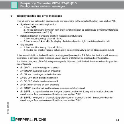
6 Display modes and error messages
The following is displayed in display mode corresponding to the selected function (see section 7.3):• Synchronisation monitoring function
1. line: SRM 2. line (as bar graph): deviation from exact synchronisation as percentage of maximum tolerated
deviation (see section 7.3.1)• Rotation direction monitoring and flow measurement functions
1. line: input frequency channel 1 in Hz 2. line: arrows or for display of rotation direction right or rotation direction left
• Slip function: 1. line: input frequency channel 1 in Hz 2. line (as bar graph): value of actual slip in percent relatively to set limit (see section 7.3.3)
If the restart inhibit or the hold function are triggered (see section 7.4.2) but the device is still in normal operation, a corresponding message (Alarm freeze or Hold) will be displayed on the display.If a fault occurs, one of the following messages is displayed until the fault is corrected (as long as this is configured): • Err LB Ch1: lead breakage on channel 1• Err LB Ch2: lead breakage on channel 2• Err LB: lead breakages on both channels• Err SC Ch1: short-circuit on channel 1• Err SC Ch2: short-circuit on channel 2• Err SC: short-circuits on both channels• Err LB/SC: one channel lead breakage, one channel short-circuit• Err SENS1: no signal on channel 1 (signal present on channel 2; only in the rotation direction
monitoring or flow measurement functions, see section 7.3.2)• Err SENS2 : no signal on channel 2 (signal present on channel 1; only in the rotation direction
monitoring or flow measurement functions, see section 7.3.2)

2811
3320
15-0
6
Frequency Converter KF**-UFT-(Ex)2.DDisplay modes and error messages
12
• Err SENS3: no overlap of sensor signals (only in the rotation direction monitoring or flow measurement functions; see section 7.3.2)
• O.Flow (for overflow): input frequency too high (all functions) or counter value too high (synchronisation monitoring; see section 7.3.1)
In all these cases, check the leads and/or sensors.• Err MEM: error in the UFT's memoryIf this fault cannot be fixed by switching the UFT off and back on, or by a reset (see section 7.6), please contact Pepperl+Fuchs.To select error messages for line monitoring, see section 7.2.1.The relays and the transistor outputs are always placed in a de-energised state in case of error, unless you have selected the hold function for a relay (see section 7.4.2). For the behavior of the current output in case of error, see section 7.5.2.

2811
3320
15-0
6
13
Frequency Converter KF**-UFT-(Ex)2.DEditing device data: Parametrisation mode control panel
7 Editing device data
7.1 Parametrisation mode control panel7.1.1 Invocation
A change in device data will change the operation of the device!Before entering new data into the device, you should therefore ascertain that no danger to the installation will result.
In this manual, the parameterisation of the device via the control panel is described. Parameterisation by means of a PC is more convenient.The necessary K-ADP-USB can be ordered from Pepperl+Fuchs. The PACTwareTM operating software and the manual are available on our Internet page www.pepperl-fuchs.com under Software > PACTware.
Main menu parameterisation mode
Display mode OK + ESC (simultaneously, 1 sec) Input (see section 7.2)ESC
Function (see section 7.3)
Output (section 7.4 and 7.5)
Service (see section 7.6)
Warning
Note

2811
3320
15-0
6
Frequency Converter KF**-UFT-(Ex)2.DEditing device data: Parametrisation mode control panel
14
You can return to display mode from any point in the menu in parameterisation mode by pressing the ESC key (possibly multiple times). If you do not press any key for 10 minutes in parameterisation mode, the device automatically switches back into display mode.
7.1.2 PasswordYou can protect the configuration from unauthorised changes using a password (see section 7.6; inactive when UFT delivered). If password protection is active, the various settings in parametrisation mode can be viewed without entering the password, but not changed. On the first attempt to make a change, the device immediately prompts for a password. The password must be entered for each transition from display mode to parametrisation mode, once each time. The password cannot be changed and is 1234. The password is entered as follows:
* If the or keys are pressed, the value changes stepwise; if the or keys are held down fora longer period, the value "rolls" to higher or lower values.
Change attempt
automatic switch to password entry Value 0, flashingParameters still protected ESC
, *: ESCOK, wrong value
new value, flashingParameters released OK, value 1234

2811
3320
15-0
6
15
Frequency Converter KF**-UFT-(Ex)2.DEditing device data: Parametrisation mode control panel
7.1.3 Navigation methodThe following diagram illustrates navigation method in the parametrisation mode using the, , OK, and ESC keys:
Output OK Rel1ESC
Rel2 OK Mode of operationESC ESC
IoutESC

2811
3320
15-0
6
Frequency Converter KF**-UFT-(Ex)2.DEditing device data: Parametrisation mode control panel
16
7.1.4 Lowest menu level: select values, enter numbersOn the lowest level of the menu, you can either select one of several possible values, or enter a number. Proceed as follows:
When entering numeric values, please note: • If you press the or keys, the value changes step by step.• If you hold the or keys, the value „rolls“ to higher or lower values. • The sign changes automatically. • The decimal point is automatically shifted. • The display will automatically switch from one unit to a higher unit, e. g. from Hz to kHz, or a factor
will be displayed, e. g. factors of 10 for numbers 10 000.
Lowest menu level
Parameter OK current value, flashingESC
, : ESC
new value, flashing
OK
new value, saved, not flashingESC

2811
3320
15-0
6
17
Frequency Converter KF**-UFT-(Ex)2.DEditing device data: Input
7.2 InputThe following illustration shows the menus for the input parameters. Menu points on the lowest level are outlined in bold. Menu items which appear only when you select the synchronisation monitoring function or the slip function (see chapter 7.3), are marked in grey.
Input —— Line monitoring (7.2.1) —— LB
SC
Pre-scaler (7.2.2) —— Channel —— CH1
CH2
Divider —— 1.000 ... 9999
Smoothing (7.2.3) —— 0 ... 250
Start-up override (7.2.4) —— 1 sec ... 250 sec

2811
3320
15-0
6
Frequency Converter KF**-UFT-(Ex)2.DEditing device data: Input
18
7.2.1 Lead monitoringThe following illustration shows the menu levels which are reached from the lead monitoring menu point. Menu points on the lowest level are outlined in bold.
If you select On for a line monitoring, the following will be checked:• LB CH1 (= lead breakage channel 1): current on terminal 3 0.15 mA• LB CH2 (= lead breakage channel 2): current on terminal 6 0.15 mA• SC CH1 (= short-circuit channel 1): current on terminal 3 6.5 mA• SC CH2 (= short-circuit channel 2): current on terminal 6 6.5 mA
Lead monitoring —— LB —— CH1 —— OFF
On
CH2 —— OFF
On
SC —— CH1 —— OFF
On
CH2 —— OFF
On

2811
3320
15-0
6
19
Frequency Converter KF**-UFT-(Ex)2.DEditing device data: Input
For lead breakage monitoring, there must be a corresponding parallel resistor in the sensor or externally, for short-circuit monitoring a corresponding series resistor in the sensor or externally (see section 5.2). For the LED displays and error messages for a lead breakage, please see section 5.3 and section 6.
7.2.2 Pre-scalerThe Pre-scaler menu item only appears when you have selected the synchronisation monitoring function or the slip function (see section 7.3). Using the pre-scaler, you can computationally adjust two different application-specific input frequencies for monitoring of synchronisation or slip. This is necessary if, for example, during monitoring the rotational speed on both sides of a transmission are measured. In such a case, use Channel to select the channel on which the higher RPM will be measured, and use Divider to specify the amount by which the higher speed should be adjusted to the lower.Example: Speed on channel 1 is 400 Hz, speed on channel 2 is 250 Hz
under Channel, select: CH1
under Divider, specify:
7.2.3 SmoothingYou can influence strongly varying frequency measured values on channel 1 with smoothing. Smoothing has effects on the monitoring of frequency trip values and on the frequency-proportional output on the current output (see section 7.3.2 and section 7.3.3).If you select a number n 1 under Smoothing, the following value will be calculated and processed instead of the measured frequency value:
Example: Under Smoothing, 3 is selected. The last value processed was 30 Hz, the current measured value 50 Hz, so the processing is as follows:
If you select the value 0 under Smoothing, the actual measured value will be processed. The larger the value set under Smoothing, the less the processed value will vary.
rotation speed 1rotation speed 2------------------------------------------- 400
250----------= = 1.600
n last processed value current measured value+n 1+
------------------------------------------------------------------------------------------------------------------------------------
3 30 Hz 50 Hz+4
---------------------------------------------- 35 Hz=

2811
3320
15-0
6
Frequency Converter KF**-UFT-(Ex)2.DEditing device data: Input
20
7.2.4 Control input I (start-up override)The effect of a signal on the control input I (terminals 13/14) are different depending on the function selected see section 7.3):• all functions: resets restart inhibit (see section 7.4.2)• Synchronisation monitoring function: reset the measured pulse difference to 0• Rotation direction monitoring function: no other effects• Flow measurement function: start-up override
If the switching direction Min is selected for relay 1 (see section 7.4), the start-up override prevents the relay from signalling a low trip value during the configured bridge period (start-up phase). In the "Active" mode (see section 7.4), the relay stays de-energised during the bridge period; in "Passive" mode, the relay is forced on during the bridge period.
• Slip function: start-up override Relay 1: as in flow measurement function Relay 2: the start-up override prevents the relay from signalling a overrun of the trip value (see
section 7.3.3). In the "Active" mode (see section 7.4), the relay stays de-energised during the bridge period; in "Passive" mode, the relay is forced on during the bridge period.
The signal on the control input I (terminals 13/14) must be applied for at least 100 ms. Before the functions described can be triggered a second time, the signal must be interrupted for at least 200 ms. If a signal interruption and new signal occur within the start-up override period, the time is restarted. A jumper on terminals 13/14 will force the described functions to be performed whenever the UFT is started, but only then.
7.2.5 Control input IIThe effect of a signal on the control input II (terminals 14/15) are also different depending on the function selected (see section 7.3):• Synchronisation monitoring function: reversal of counter direction (level triggered, see section 7.3.1)• Rotation direction monitor and flow measurement functions: display is set to clockwise rotation and
an eventually present fault SensError is reset (flank triggered, see section 7.3.2)• Slip function: slip is reset to 0 (level triggered, see section 7.3.3)

2811
3320
15-0
6
21
Frequency Converter KF**-UFT-(Ex)2.DEditing device data: Function
7.3 FunctionThe following illustrations show the menus for function selection. Menu points on the lowest level are outlined in bold. The active function of the UFT (SRM for synchronisation monitoring, DRM for rotation direction monitoring, Flow for flow measurement, or Slip for slip monitoring) is marked On. If you want to activate a different function, first call it up with the and keys. Then press the OK key twice. After the first OK you can cancel with ESC.
Function —— SRM (7.3.1) —— Difference pulses —— 0 ... 30000
DRM (7.3.2) —— Switching pulses —— 1 ... 250
Flow (7.3.2) —— Switching pulses —— 1 ... 250
Slip (7.3.3) —— Iout function —— frequency
Slip
Trip value —— 3 % ... 99 %
continued on next page

2811
3320
15-0
6
Frequency Converter KF**-UFT-(Ex)2.DEditing device data: Function
22
Hysteresis —— 2 % ... 98 %
Accuracy —— 1 %
2 %
3 %
4 %
5 %
7 %
10 %
20 %

2811
3320
15-0
6
23
Frequency Converter KF**-UFT-(Ex)2.DEditing device data: Function
7.3.1 Synchronisation monitoringIn synchronisation monitoring, the total pulses counted on channel 1 and the total pulses counted on channel 2 are compared. RelayIf the difference between the pulses counted on channel 1 and channel 2 exceeds the value configured under Difference pulses (maximum tolerable deviation) and if channel 1 is leading (larger number of pulses), relay 1 switches. If the mesaured pulse difference exceeds the value configured under Difference pulses and channel 2 is leading, Relay 2 switches. The direction of activation of both relays can be selected independently (see section 7.4). The following table gives an overview of the relay behaviour.
A relay which has switched after the configured difference pulses are exceeded is reset when the measured pulse difference is again 0.Current outputIt can always be detected from the current output which channel is leading: at synchronisation, the mean value of the output range is placed on the current output (10 mA or 12 mA; see section 7.5.1). If channel 1 is leading, a larger value is output; if channel 2 is leading, a smaller value. As long as the measured pulse difference is smaller than the configured difference pulses, the current output is calculated as
The following table shows show examples for the current output. Please note that the behaviour of the current output when the configured pulse difference value is exceeded is determined by the characteristic curve (see section 7.5.1).
Direction ofactivity
Exceeding configured difference pulsesChannel 1 leading Channel 2 leading
Relay 1 Relay 2 Relay 1 Relay 2Active energised de-energised de-energised energised
Passive de-energised energised energised de-energised
?
Mean value of output rangemeasured pulse difference
configured difference pulses--------------------------------------------------------------------------- size of output range
2----------------------------------------------------

2811
3320
15-0
6
Frequency Converter KF**-UFT-(Ex)2.DEditing device data: Function
24
Configured difference pulses: 4
Transistor outputsThe pulses from channel 1 are switched over transistor output 1, and the pulses from channel 2 over transistor output 2. These pulses can then be evaluated in the process control system. The KF**-UFT-Ex2.D thus serves as an isolator between the intrinsically safe and non-intrinsically safe circuits.Control input II: reversing counter directionIn synchronisation monitoring, the pulses incoming on channel 1 and those on channel 2 are simply counted. A direction reversal within the application must be signalled to the UFT using a signal on control input II (terminals 14 and 15; not intrinsically safe!) As long as a signal is applied to control input II, the UFT counts downwards.Example: In a lift platform with two lifting jacks, the synchronous movements of the jacks are monitored using a rotational pulse sensor. When lifting, jack 2 runs faster than jack 1, but the resulting tilt remains within tolerance (measured pulse difference smaller than the configured difference pulses). When lowering, jack 2 still runs faster than jack 1. The tilt is thus corrected. The UFT, however, continues counting, registers a further increase in the measured pulse difference, and signals a faulty synchronisation. To prevent this, during lowering a signal is applied to control input II. As long as this signal is applied, the UFT counts downwards.
Leading channel
Pulse difference
Characteristic0 mA ... 20 mA
Characteristic4 mA ... 20 mA, according
to NAMUR NE 43
Characteristic4 mA ... 20 mA
neither 0 10 mA 12 mA 12 mACH1 1 12.5 mA 14 mA 14 mACH2 2 5 mA 8 mA 8 mACH1 3 17.5 mA 18 mA 18 mACH2 4 0 mA 4 mA 4 mACH1 5 20.5 mA 20.5 mA 21.5 mACH2 6 0 mA 3.8 mA 0 mA

2811
3320
15-0
6
25
Frequency Converter KF**-UFT-(Ex)2.DEditing device data: Function
7.3.2 Rotation direction monitoring and flow measurementIn rotation direction monitoring and flow measurements, pulses coming in on channel 1 and channel 2 are checked for their order. The UFT expects alternating signals on channel 1, then on channel 2. If one channel misses a beat, the error message ERR SENS 1 or ERR SENS 2 is generated.The pulses must have the same frequency, be at least 250 s wide, and overlap by at least 125 s. If this is not the case, the error message ERR SENS 3 is generated.Clockwise rotation is signalled when the impulses on channel 1 arrive before those on channel 2; counter-clockwise when pulses on channel 2 arrive before those on channel 1.The parameter Switching pulses influences the switching of the rotation direction display. The UFT only signals a change in direction when as many pulses in this other direction are received as selected in the Switching pulses parameter.
In the start state, clockwise rotation is displayed.
Display clockwise
Ch. 1
Ch. 2
Displaycounter-clockw
actualclockwise
zero crossing > 20 ms actual counter-clockwise
Time
> 250 s
> 125 s

2811
3320
15-0
6
Frequency Converter KF**-UFT-(Ex)2.DEditing device data: Function
26
Relay in rotation direction monitoringThe following table gives an overview of the relay behaviour during rotation direction monitoring. The direction of activation of both relays can be selected independently (see section 7.4).
Relay in flow measurementRelay 1 serves as a frequency trip value monitor for channel 1 in flow measurement (see section 7.4.1). The behaviour of relay 2 in flow measurement is shown in the following table; for a list of the activity direction see section 7.4.1.
Current output in rotation direction monitoring and flow measurementOn the current output, a signal is output which is proportional to the frequency measured on channel 1. The start and end values of the frequency range are freely configurable (see section 7.5).Transistor outputs in rotation direction monitoringThe pulses from channel 1 are switched over transistor output 1, and the pulses from channel 2 over transistor output 2. These pulses can then be evaluated in the process control system.The KF**-UFT-Ex2.D thus serves as an isolator between the intrinsically safe and non-intrinsically safe circuits.Transistor outputs in flow measurementIf the UFT displays counter-clockwise, the pulses from channel 1 are switched over transistor output 1. If the UFT displays clockwise, the pulses from channel 1 are switched over transistor output 2. These pulses can then be evaluated in the process control system. The KF**-UFT-Ex2.D thus serves as an isolator between the intrinsically safe circuit and the non-intrinsically safe circuits.
Mode of operation Clockwise:channel 1 before channel 2
Counter-clockwise:channel 2 before channel 1
Relay 1 Relay 2 Relay 1 Relay 2
Active energised de-energised de-energised energisedPassive de-energised energised energised de-energised
Mode of operation Clockwise:channel 1 before channel 2
Counter-clockwise:channel 2 before channel 1
Active de-energised energisedPassive energised de-energised

2811
3320
15-0
6
27
Frequency Converter KF**-UFT-(Ex)2.DEditing device data: Function
Control input II in rotation direction monitoring and flow measurementIn the start state, the UFT shows clockwise. Using a signal on control input II (terminals 14 and 15) you can reset the display of the UFT back to clockwise during operation (e. g. when starting up the system). The signal must be applied for at least 100 ms.
7.3.3 Slip monitoringIn slip monitoring, the relationship between the frequencies (measured within the time window) on channel 1 and channel 2 are monitored, or more exactly, the value defined as
The frequency on channel 1 must always be larger than the frequency on channel 2. When the UFT starts up, a slip of 0 % is output.Application example: A motor drives a conveyor belt over a drive belt. The frequency measured at the motor is input on channel 1, that on the conveyor on channel 2. RelayRelay 1 serves as a frequency trip value indicator for channel 1 (see section 7.4.1). Relay 2 serves as a trip value indicator for the slip (switching direction always Max; for the switching behaviour of the relays, see section 7.4.1). Please note that the trip value and hysteresis for relay 2 must be configured in the menu Function Slip, and all other parameters for the relays under Output Rel1 or Output Rel2.Current outputIf you select Iout function frequency, the output on the current output is proportional to the frequency on channel 1. The start and end values of the frequency range are freely configurable (see section 7.5).If you select Iout function slip, the output on the current output is proportional to the slip. The starting value is always 0 %, the end value always 100 %.
Time window
Slip = 1 Frequency channel 2Frequency channel 1--------------------------------------------------------–
100 %

2811
3320
15-0
6
Frequency Converter KF**-UFT-(Ex)2.DEditing device data: Function
28
Transistor outputsThe pulses from channel 1 are switched over transistor output 1, and the pulses from channel 2 over transistor output 2. These pulses can then be evaluated in the process control system.The KF**-UFT-Ex2.D thus serves as an isolator between the intrinsically safe and non-intrinsically safe circuits.Control input IIAs long as a signal is applied to control input II (terminals 14 and 15), the trip value for the slip is not monitored.AccuracyTo measure low frequencies accurately, a longer measurement time (in comparison with measurements at higher frequencies) is necessary. This can lead to undesirably slow reaction times of the UFT to a trip value in slip monitoring. In such cases, you can use the parameter Accuracy to lower the measurement time and thus the reaction time of the UFT at the expense of measurement accuracy. This equation holds:
If you set the parameter Accuracy to the value 2 %, only half as long as measurement time will result as when you choose 1 %; at the value 20 %, the measurement time is only 1/20 of the measurement time at the 1 % setting.At setting 1 %, input frequencies which differ by more than 1 % already lead to different measurement results in the UFT; at the 2 % setting, input frequencies must differ by more than 2 %, and so on. At setting 20 %, therefore, input frequencies which differ by 20 % may lead to the same measurement result.Thus is it important, for low input frequencies or when using a large pre-scaler (see section 7.2.2) to find the right compromise for your application between measurement time and measurement accuracy.
Measurement time 100%Accuracy Frequency channel 1-------------------------------------------------------------------------------------=

2811
3320
15-0
6
29
Frequency Converter KF**-UFT-(Ex)2.DEditing device data: Relay output
7.4 Relay outputThe following illustrations show the menus for the output parameters. Menu points on the lowest level are outlined in bold. Menu items which only appear when you have selected particular functions are shown on a grey background.Trip value and hysteresis for relay 2 for the slip function are configured in the menu Function Slip. The switching direction of relay 2 in the slip function is always Max.
Output —— Rel1 (7.4.1) —— Trip value —— 0.001 Hz ... 1000 Hz
Hysteresis —— 0.005 Hz ... 999.9 Hz
Min/Max —— Min
MAX
Mode of operation —— Passive
Active
Alarm freeze (7.4.2) —— OFF
On
continued on next page continued on next page

2811
3320
15-0
6
Frequency Converter KF**-UFT-(Ex)2.DEditing device data: Relay output
30
Hold (7.4.2) —— OFF
On
Rel2 (7.4.1) —— Mode of operation —— Passive
Active
Alarm freeze (7.4.2) —— OFF
On
Hold (7.4.2) —— OFF
On
Iout (7.5)

2811
3320
15-0
6
31
Frequency Converter KF**-UFT-(Ex)2.DEditing device data: Relay output
7.4.1 Switching behaviour of the relays
The switching direction for relay 1 is configurable as either Min or Max . Relay 2 always has switching direction Max. The activation directions for the two relays are independently configurable as either Active or Passive. Areas of application:• Switching mode MAX, operating mode Active: alarm on over range, for instance audible alarm• Switching mode MAX, operating mode Passive: monitoring of a trip value, for instance pump/system
off; for larger hysteresis, MIN-MAX mode (on/off)• Switching mode MIN, operating mode Active: alarm when below range, for instance audible alarm• Switching mode MIN, operating mode Passive: overload protection, monitoring of a trip value
undervalue, for instance pump off, if nothing more is flowingThe exact switching behaviour of the UFT can be seen in the following illustration on page 32.The hysteresis should be > 1 % of the trip value, in order to prevent rapid switching of the relay.In the switching direction MAX, the value Switch point - Hysteresis > 0 must be true, and for switching direction MIN the value Trip value + Hysteresis Upper limit of trip value input. These input limits are automatically supplied by the UFT.
The information in chapter 7.4.1 is valid for relay 1 in the functions Flow measurement and Slip (frequency trip value monitor), and for relay 2 in the function slip (slip trip value monitor). The switching behaviour of the relays for other functions can be found in section 7.3.Note

2811
3320
15-0
6
Frequency Converter KF**-UFT-(Ex)2.DEditing device data: Relay output
32
7.4.2 Restart inhibit and holdWith the restart inhibit, you prevent a short-term triggering of the relay, such as a short-term value above the trip value, from going unnoticed by operating personnel.In the function Rotation direction monitor (see section 7.3.2), a restart inhibit would have no meaning in practice. The menu item in this case does not appear for the two relays.• If Alarm freeze On is selected, the new state remains valid after the relay has tripped, until one of the
following actions: Pressing the ESC key. Signal on terminals 13/14 Device restartedEach of these actions resets the relay, unless the reason for the tripping of the relay is still present.
energisedde-energised
Trip value MinMin + Hysteresis
Max - HysteresisTrip value Max
energisedde-energised
energisedde-energised
energisedde-energised
Measured value
TimeSwitching mode Max, operating mode Acitve:
Switching mode Max, operating mode Passive:
Switching mode Min, operating mode Active:
Switching mode Min, operating mode Passive:

2811
3320
15-0
6
33
Frequency Converter KF**-UFT-(Ex)2.DEditing device data: Current output
• If you select Alarm freeze for relay 1 with switching direction MIN, the start-up override must be triggered on device start-up (see section 7.2.4). The UFT starts with a value of 0. This would immediately trigger a MIN alarm. Without start-up override, the relay would then be blocked by the restart inhibit.
Using the function Hold, you prevent the relay from switching off after an error message (for the different messages, see section 6). If Hold On is selected, the state remains in effect which the relay was in before the error. Once the error message has been released, the relay resumes normal operation.
7.5 Current outputThe following illustrations show the menus for the parameters of the current output. Menu points on the lowest level are outlined in bold. Menu points which only appear when you have selected Rotation direction monitor, Flow measurement or Slip Iout function Frequency (see section 7.3), are shown with a grey background.
Output —— Rel1 (7.4)
Rel2 (7.4)
Iout —— Characteristic (7.5.1) —— 0 mA ... 20 mA
4 mA ... 20 mA, NAMUR NE 43
4 mA ... 20 mA
continued on next page

2811
3320
15-0
6
Frequency Converter KF**-UFT-(Ex)2.DEditing device data: Current output
34
7.5.1 CharacteristicThe meanings of the different settings for the characteristic curve are listed on the following pages. Pleas note:• If you select a function of Rotation direction monitor, Flow measurement or Slip
Iout function Frequency (see section 7.3), the start and end values may be freely set within the given limits. The difference between the end value and the start value should be more than 1 % of the end value.
• If you select a function of Slip Iout function Slip (see section 7.3), the start value is always 0 %, the end value always 100 %.
• If you select an inverted characteristic, the conversion of start value and end value will be exchanged.
Start value —— 0.000 Hz ... 999.9 Hz
End value —— 0.010 Hz ... 1000 Hz
Inverted —— Normal
Inverted
Fault current (7.5.2) —— Min
MAX
Hold

2811
3320
15-0
6
35
Frequency Converter KF**-UFT-(Ex)2.DEditing device data: Current output
Setting 0 mA ... 20 mA
For this setting the start value will be converted to 0 mA, and the end value to 20 mA; intermediate values will be converted proportionally. A value below the start point cannot be evaluated (output 0 mA). For values above the end point, the output current increases linearly to a maximum of 20.5 mA (102.5 % of the measurement range). Further increases cannot be evaluated (output 20.5 mA).Setting 4 mA ... 20 mA, according to NAMUR NE 43
For this setting the start value will be converted to 4 mA, and the end value to 20 mA; intermediate values will be converted proportionally. A value below the start value will result in the output current sinking linearly to a minimum of 3.8 mA (-1.25 % of the measurement range). Further underflows cannot be evaluated (output 3.8 mA). For values above the end point, the output current increases linearly to a maximum of 20.5 mA (about 103 % of the measurement range). Further increases cannot be evaluated (output 20.5 mA).
20,520,0
00 100 102,5
mA
%
20,520,0
00 100 103- 1,25
4,03,8
mA
%

2811
3320
15-0
6
Frequency Converter KF**-UFT-(Ex)2.DEditing device data: Current output
36
Setting 4 mA ... 20 mA
For this setting the start value will be converted to 4 mA, and the end value to 20 mA; intermediate values will be converted proportionally. A value below the start value will result in the output current sinking linearly to a minimum of 0 mA (- 25 % of the measurement range). Further underflows cannot be evaluated (output 0 mA). For values above the end point, the output current increases linearly to a maximum of up to 21.5 mA (about 110 % of the measurement range). Further rises cannot be evaluated (output about 21.5 mA).
7.5.2 Fault currentThe following table shows what the current output is during a fault, depending on the settings:
Setting Characteristic0 mA ... 20 mA
Characteristic4 mA ... 20 mA,
acc. to NAMUR NE 43
Characteristic4 mA ... 20 mA
Hold last value before the faultMax(upscale) about 21.5 mA about 21.5 mA
about 21.5 mA (cannot be distinguished value exceeding end value)
Min(downscale)
0 mA (cannot be distinguished from measurement at start value)
2.0 mA2.0 mA (cannot be distinguished from out of range)
21,520,0
00 100 110- 25
4,0
mA
%

2811
3320
15-0
6
37
Frequency Converter KF**-UFT-(Ex)2.DEditing device data: Service
7.6 ServiceThe following illustration shows the menus for the service parameters. Menu points on the lowest level are outlined in bold.
Reset: If yes is flashing and you press the OK key, all the settings of the UFT will be reset to the factory settings (see section 7.7). All entries which you have ever made in parametrisation mode will be lost.
Service —— Language —— ENG (English)
GER (German)
Password (7.1.2) —— OFF
On
Reset (see below) —— yes
no

2811
3320
15-0
6
Frequency Converter KF**-UFT-(Ex)2.DEditing device data: Factory settings
38
7.7 Factory settingsParameter Factory setting Local settingLB/SC CH1/CH2 all: OFFPre-scaler channel CH2Pre-scaler ratio 1.000Smoothing 0Start-up override 10 secSRM/DRM/Flow/Slip Slip OnSRM Difference pulses 100DRM/Flow Switching pulses both: 2Slip Iout function FrequencySlip Trip value 50 %Slip hysteresis 5 %Slip accuracy 1 %Rel1 Trip value 100 HzRel1 Hysteresis 50 HzRel1 MIN / MAX MINRel1/Rel2: Activation dir. both: PassiveRel1/Rel2: Alarm freeze both: OFFRel1/Rel 2: Hold both: OFFIout characteristic 4 - 20 NE 43 Iout start value 0.000 HzIout final value 200.0 HzIout inverted NormalIout fault current MinPassword OFFLanguage GER (= German)Reset No

2811
3320
15-0
6
39
Frequency Converter KF**-UFT-(Ex)2.DNotes

2811
3320
15-0
6
Frequency Converter KF**-UFT-(Ex)2.DNotes
40

2811
3320
15-0
6
41
Frequency Converter KF**-UFT-(Ex)2.DNotes

Subject to modificationsCopyright PEPPERL+FUCHS · Printed in Germany
www.pepperl-fuchs.com
Worldwide HeadquartersPepperl+Fuchs GmbH68307 Mannheim · GermanyTel. +49 621 776-0E-Mail: [email protected] the Pepperl+Fuchs representativeclosest to you check www.pepperl-fuchs.com/contact
PROCESS AUTOMATION –PROTECTING YOUR PROCESS
281133 DOCT-0608E06/2015