technical instructions for safety recall … instructions for safety recall e0m sprial cable...
TRANSCRIPT

TECHNICAL INSTRUCTIONS
FOR
SAFETY RECALL E0M
SPRIAL CABLE REPLACEMENT
CERTAIN 2009 –2010 MY COROLLA, 2009 – 2010 MY COROLLA MATRIX,
2008 – 2010 MY HIGHLANDER, 2006 – 2008 MY RAV4,
2009 – 2010 MY TACOMA, 2006 – 2010 MY YARIS VEHICLES
UPDATED SEPTEMBER 22, 2017
9-21-2017 - Added inspection for Rav4 Models - Added step in flowchart
All dealership associates involved in the recall process are required to successfully complete E-Learning course SC13A. To ensure that all vehicles have the repair performed correctly; technicians performing this recall repair are required to currently hold at least one of the following certifications levels: • Toyota Certified (Electrical) • Toyota Expert (Electrical) • Master • Master Diagnostic Technicians

2
I. OPERATION FLOW CHART
Verify Vehicle Eligibility1. Check the VIN range.
2. Check the TIS Vehicle Inquiry System.
No further action required.Not Covered
Campaign complete.Return the vehicle to the customer.
Covered
Is vehicle a Rav4?
No
Replace spiral cable Does Rav4 spiral cable have 2 connectors?
Yes
Yes
No
II. IDENTIFICATION OF AFFECTED VEHICLES
NOTE: • Check the TIS Vehicle Inquiry System to confirm the VIN is covered in this Safety Recall, and that the campaign
has not already been completed by another dealer. • TMS warranty will not reimburse dealers for repairs conducted on vehicles that are not affected or were
completed by another dealer.

3
III. PREPARATION
A. PARTS
Model Part Number Part Description (kit contents) Quantity
All 04004-07122 E0M Spiral Cable Kit
(spiral cable p/n 84306-04080 and grease packet p/n 84323-42010)
1
B. TOOLS & EQUIPMENT
• Standard hand tools • Techstream 2.0 / TIS Techstream /Techstream Lite (Software 8.30 or Higher) • "TORX" Socket T30 • Torque wrench SST – This is an essential special service tool that the dealership should have.
Tool Number Tool Name 09950-50013 Universal Puller Set C
C. MATERIALS
・ Protective tape ・ Marker pen
IV. BACKGROUND The steering column assembly in the involved vehicles contains a spiral cable assembly with electrical connections to the driver’s airbag module that could become damaged when the steering wheel is turned. If this occurs, the air bag warning lamp will illuminate. In addition, the driver’s air bag could become deactivated, causing it to not deploy in the event of a crash. This could increase the risk of injury to the driver.

4
V. SPRIAL CABLE REPLACEMENT
Note: This is a general picture of the steering column with the spiral cable each vehicle covered by this
SSC may differ. Refer to the Technical Information System (TIS), using applicable vehicle and model year for the correct illustration.
SPIRAL CABLE SUB-ASSEMBLY

5
NOTE: THIS STEP IS FOR RAV4 VEHICLES ONLY
0. CHECK THE NUMBER OF SPIRAL CABLE CONNECTORS a. Remove steering pad assembly
- Straighten the front wheels - Using a T30 "TORX" driver, loosen the 2 screws until the
groove along each screw circumference catches on the screw case
- Pull out the steering pad from the steering wheel and support the steering pad with one hand
NOTE: THIS STEP IS FOR RAV4 VEHICLES ONLY
b. Check the number of spiral cable connectors
-1 Connectors – Go to Step 1
-2 Connectors - Campaign complete, return vehicle to customer

6
1. CHECK FOR DTCs a) Perform a Health Check. b) Check for any DTC’s c) Record any DTC’s NOTE: This campaign covers issues related to the spiral cable. If any other DTC’s are Pending, Current, and/or History. Verify warranty coverage and refer to the appropriate repair manual on TIS for proper diagnosis and repair. If vehicle is not covered under warranty, advise the customer prior to diagnosing or repairing the vehicle.
2. REMOVE THE SPIRAL CABLE
• Follow all precautions as outlined on TIS before servicing the SRS system. • Wait at least 90 seconds after disconnecting the cable from the negative battery terminal
to prevent airbag and seat belt pre-tensioner deployment.
a) Refer to the Technical Information System (TIS), using the applicable vehicle and model year for spiral cable
removal:
2009 MY Corolla
2009 MY Highlander
2009 MY Tacoma
2009 MY Yaris
2010 MY Corolla
2010 MY Highlander
2010 MY Tacoma
2010 MY Yaris
2009 MY Corolla Matrix
2006 MY RAV4
2006 MY Yaris
2010 MY Corolla Matrix
2007 MY RAV4
2007 MY Yaris
2008 MY Highlander
2008 MY RAV4
2008 MY Yaris

7
Note: Prior to removing the steering column cover on the RAV4 review these steps to avoid damaging the claws.
Failure to observe the procedure instructed below could cause the claws of the steering column covers to be broken.
Disengage the claws of the upper column cover by pushing on the areas highlighted by the arrows, on each side as shown in the illustration below.
While holding the upper column cover and pushing on the areas highlighted in the illustration below, move the lower column cover downward.
Even if a service hole is provided, DO NOT push on the cover with a screwdriver through that hole. Doing so could cause the claw to be broken.

8
Pull the lower column cover toward you to detach it from the steering column.
a) Raise the upper column cover as shown in the illustration to disengage the claw.
The back of the upper column cover is attached to the fabric DO NOT forcibly raise the cover.
b) Place cloths over the meter hood, and then set the upper column cover against the hood.

9
3. Remove the Steering Angle Sensor if equipped (if not equipped go to Step 5)
a) Locate the 6 clips on the old spiral cable. Note: The Steering Angle Sensor will be
reused.
The Steering Angle Sensor has already been removed in this picture for clarity.
b) Break off the 6 clips from the spiral cable.
c) Disengage the steering angle sensor from
the spiral cable.
4. Install the Steering Angle Sensor onto the new Spiral Cable
DO NOT break/snap off the lock pin until prior to installing the steering wheel. Otherwise, the center position of a new spiral cable will be misaligned.

10
a) In order to prevent noise from occurring, apply a small amount of grease (included in the new spiral cable kit) onto the surface at the 4 locations shown in the illustration.
NOTE: Apply approximately a 2mm thick covering on the
surfaces as shown in the illustration.
b) Align the tabs of the steering angle sensor with the new spiral cable Note: Place the large tab at the 12 o’clock position
c) Install the steering angle sensor onto the new spiral cable and ensure the 6 clips engage the 6 ears.
5. INSTALL THE NEW SPIRAL CABLE
Refer to the Technical Information System (TIS), using the applicable vehicle and model year for spiral cable installation:
2009 MY Corolla
2009 MY Highlander
2009 MY Tacoma
2009 MY Yaris
2010 MY Corolla
2010 MY Highlander
2010 MY Tacoma
2010 MY Yaris
2009 MY Corolla Matrix
2006 MY RAV4
2006 MY Yaris
2010 MY Corolla Matrix
2007 MY RAV4
2007 MY Yaris
2008 MY Highlander
2008 MY RAV4
2008 MY Yaris

11
Prior to reinstalling the steering wheel ensure the following
• DO NOT rotate the spiral cable prior to installing the steering wheel, the new spiral cable will be correctly centered.
• If the spiral cable has been rotated, you must recenter the spiral cable prior to installation. 1. Turn the cable counterclockwise by hand until it becomes
hard to turn. 2. Turn the cable clockwise about 2.5 turns. 3. Confirm the alignment marks align AND the orange roller is
visible in the window.
4. After removing the lock pin inspect the spiral cable for any portion of the lock pin that may remain in the spiral cable.
5. If a portion of the lock pin protrudes above the surface of the spiral cable, push it in until it is flush or slightly below the surface.
12
6. TEST DRIVE VEHICLE
◄ VERIFY REPAIR QUALITY ► − Confirm there are no abnormal noises from the steering column − Confirm the SRS warning light goes out after starting the vehicle − Confirm there are no DTCs in the SRS and ABS systems
If you have any questions regarding this update, please contact your regional representative
VI. APPENDIX
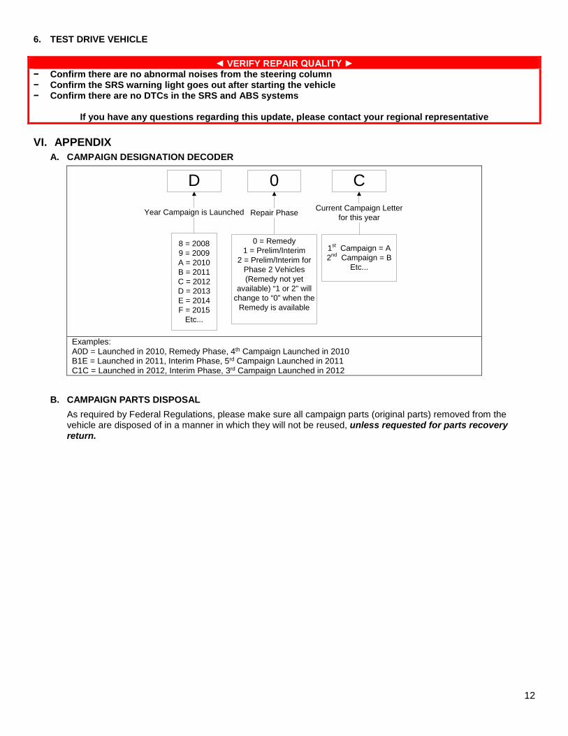
A. CAMPAIGN DESIGNATION DECODER
D 0 C
Year Campaign is Launched
8 = 20089 = 2009A = 2010B = 2011C = 2012 D = 2013E = 2014F = 2015
Etc...
Repair Phase
1st Campaign = A2nd Campaign = B
Etc...
Current Campaign Letter for this year
0 = Remedy1 = Prelim/Interim
2 = Prelim/Interim for Phase 2 Vehicles(Remedy not yet
available) “1 or 2” will change to “0” when the
Remedy is available
Examples: A0D = Launched in 2010, Remedy Phase, 4th Campaign Launched in 2010 B1E = Launched in 2011, Interim Phase, 5rd Campaign Launched in 2011 C1C = Launched in 2012, Interim Phase, 3rd Campaign Launched in 2012
B. CAMPAIGN PARTS DISPOSAL
As required by Federal Regulations, please make sure all campaign parts (original parts) removed from the vehicle are disposed of in a manner in which they will not be reused, unless requested for parts recovery return.