switchable focus using a polymeric lenticular microlens
TRANSCRIPT
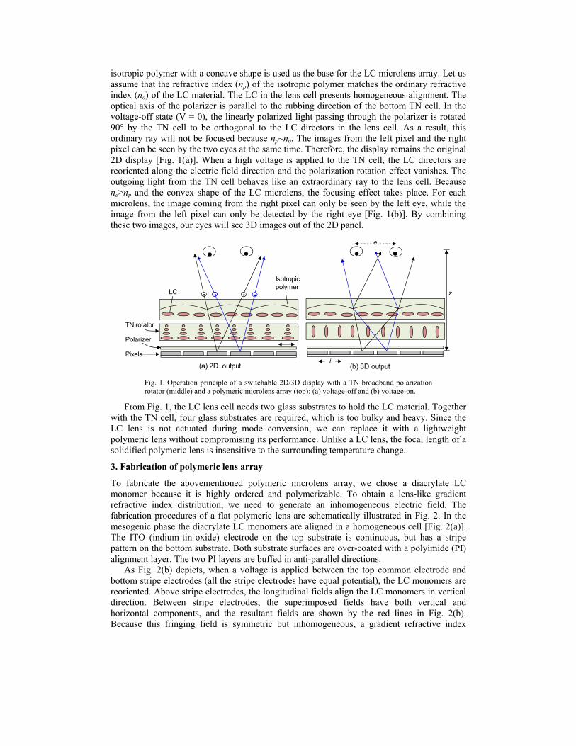
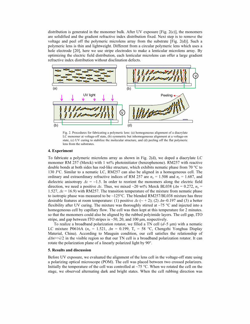
distribution is generated in the monomer bulk. After UV exposure [Fig. 2(c)], the monomers are solidified and the gradient refractive index distribution fixed. Next step is to remove the voltage and peel off the polymeric microlens array from the substrate [Fig. 2(d)]. Such a polymeric lens is thin and lightweight. Different from a circular polymeric lens which uses a hole electrode [20], here we use stripe electrodes to make a lenticular microlens array. By optimizing the electric field distribution, each lenticular microlens can offer a large gradient refractive index distribution without disclination defects.
(b)
(a) (b)
(d)(b)
UV light Peeling
V
V
Fig. 2. Procedures for fabricating a polymeric lens: (a) homogeneous alignment of a diacrylate LC monomer at voltage-off state, (b) symmetric but inhomogeneous alignment at a voltage-on state, (c) UV curing to stabilize the molecular structure, and (d) peeling off the flat polymeric lens from the substrates.
4. Experiment
To fabricate a polymeric microlens array as shown in Fig. 2(d), we doped a diacrylate LC monomer RM 257 (Merck) with 1 wt% photoinitiator (benzophenone). RM257 with reactive double bonds at both sides has rod-like structure, which exhibits nematic phase from 70 °C to 130 J°C. Similar to a nematic LC, RM257 can also be aligned in a homogeneous cell. The ordinary and extraordinary refractive indices of RM 257 are no = 1.508 and ne = 1.687, and dielectric anisotropy Δε = −1.5. In order to reorient the monomers along the electric field direction, we need a positive Δε. Thus, we mixed ~20 wt% Merck BL038 (Δn = 0.272, no = 1.527, Δε = 16.9) with RM257. The transition temperature of the mixture from nematic phase to isotropic phase was measured to be ~125°C. The blended RM257/BL038 mixture has three desirable features at room temperature: (1) positive Δε (~ + 2); (2) Δn~0.197 and (3) a better flexibility after UV curing. The mixture was thoroughly stirred at ~75 °C and injected into a homogeneous cell by capillary flow. The cell was then kept at this temperature for 2 minutes. so that the monomers could also be aligned by the rubbed polyimide layers. The cell gap, ITO stripe, and gap between ITO stripes is ~50, 20, and 100 μm, respectively.
To realize a broadband polarization rotator, we filled a TN cell (d~5 μm) with a nematic LC mixture P0616A (no = 1.521, Δn = 0.199, Tc = 58 °C, Chengzhi Yonghua Display Material, China). According to Mauguin condition, our cell satisfies the relationship of dΔn>>λ/2 in the visible region so that our TN cell is a broadband polarization rotator. It can rotate the polarization plane of a linearly polarized light by 90°.
5. Results and discussion
Before UV exposure, we evaluated the alignment of the lens cell in the voltage-off state using a polarizing optical microscope (POM). The cell was placed between two crossed polarizers. Initially the temperature of the cell was controlled at ~75 °C. When we rotated the cell on the stage, we observed alternating dark and bright states. When the cell rubbing direction was
#184486 - $15.00 USD Received 30 Jan 2013; revised 26 Feb 2013; accepted 27 Feb 2013; published 25 Mar 2013(C) 2013 OSA 8 April 2013 / Vol. 21, No. 7 / OPTICS EXPRESS 7919
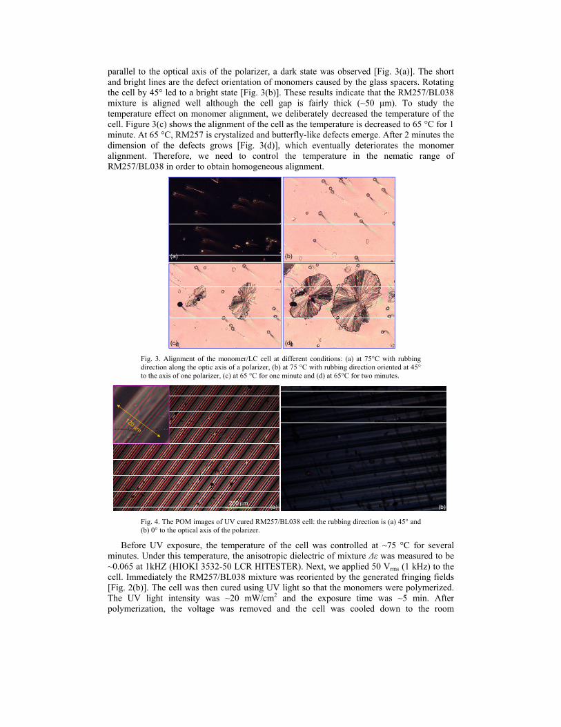
parallel to the optical axis of the polarizer, a dark state was observed [Fig. 3(a)]. The short and bright lines are the defect orientation of monomers caused by the glass spacers. Rotating the cell by 45° led to a bright state [Fig. 3(b)]. These results indicate that the RM257/BL038 mixture is aligned well although the cell gap is fairly thick (~50 μm). To study the temperature effect on monomer alignment, we deliberately decreased the temperature of the cell. Figure 3(c) shows the alignment of the cell as the temperature is decreased to 65 °C for 1 minute. At 65 °C, RM257 is crystalized and butterfly-like defects emerge. After 2 minutes the dimension of the defects grows [Fig. 3(d)], which eventually deteriorates the monomer alignment. Therefore, we need to control the temperature in the nematic range of RM257/BL038 in order to obtain homogeneous alignment.
(a) (b)
(c) (d)
Fig. 3. Alignment of the monomer/LC cell at different conditions: (a) at 75°C with rubbing direction along the optic axis of a polarizer, (b) at 75 °C with rubbing direction oriented at 45° to the axis of one polarizer, (c) at 65 °C for one minute and (d) at 65°C for two minutes.
(a) (b)200 μm
Fig. 4. The POM images of UV cured RM257/BL038 cell: the rubbing direction is (a) 45° and (b) 0° to the optical axis of the polarizer.
Before UV exposure, the temperature of the cell was controlled at ~75 °C for several minutes. Under this temperature, the anisotropic dielectric of mixture Δε was measured to be ~0.065 at 1kHZ (HIOKI 3532-50 LCR HITESTER). Next, we applied 50 Vrms (1 kHz) to the cell. Immediately the RM257/BL038 mixture was reoriented by the generated fringing fields [Fig. 2(b)]. The cell was then cured using UV light so that the monomers were polymerized. The UV light intensity was ~20 mW/cm2 and the exposure time was ~5 min. After polymerization, the voltage was removed and the cell was cooled down to the room
#184486 - $15.00 USD Received 30 Jan 2013; revised 26 Feb 2013; accepted 27 Feb 2013; published 25 Mar 2013(C) 2013 OSA 8 April 2013 / Vol. 21, No. 7 / OPTICS EXPRESS 7920
temperature. To inspect how the electric field affects the orientation of the formed polymer, we observed the birefringence colors under POM. The cell was placed on the microscope stage between crossed polarizers. The rubbing direction of the cell was oriented at 45° with respect to the transmission axis of the polarizer. Figure 4(a) shows the observed interference color which has a periodic stripe patterns. The color stripes between adjacent black lines (ITO stripes) imply that the polymer presents a gradient refractive index distribution. In each period, the solidified polymer exhibits lenticular lens characteristics. So the cell functions as a lenticular microlens array. The insert is the enlarged texture of one period, and the lens aperture is 120 μm. The tiny black spots in Fig. 4(a) are the defects which present the butterfly-like structure shown in Fig. 3(d). Because the temperature of the cell is slightly higher than the phase transition temperature of the monomer (from nematic to crystal phase), when the cell is transferred from the hot plate to the stage of the microscope, some domains in the mixture become crystallized as the temperature decreases. To minimize the defects, a constant temperature is important during the preparation of polymeric lens, and a temperature controller should be taken into account in future. The cell was then rotated by another 45° so that its rubbing direction is parallel to the optical axis of polarizer. A very dark state is observed [Fig. 4(b)] indicating that the polymeric microlens is indeed optically anisotropic. Its optical axis is along the rubbing direction of the cell.
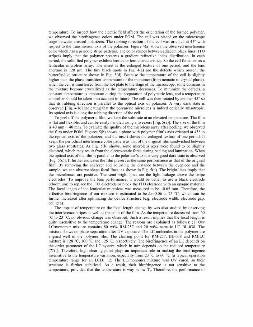
To peel off the polymeric film, we kept the substrate at an elevated temperature. The film is flat and flexible, and can be easily handled using a tweezers [Fig. 5(a)]. The size of the film is 40 mm × 40 mm. To evaluate the quality of the microlens array after peeling, we observed the film under POM. Figures 5(b) shows a photo with polymer film’s axis oriented at 45° to the optical axis of the polarizer, and the insert shows the enlarged texture of one period. It keeps the periodical interference color pattern as that of the original film sandwiched between two glass substrates. As Fig. 5(b) shows, some microlens axes were found to be slightly distorted, which may result from the electro-static force during peeling and lamination. When the optical axis of the film is parallel to the polarizer’s axis, a very good dark state is observed [Fig. 5(c)]. It further indicates the film preserves the same performance as that of the original film. By removing the analyzer and adjusting the distance between the eyepiece and the sample, we can observe shape focal lines, as shown in Fig. 5(d). The bright lines imply that the microlenses are positive. The semi-bright lines are the light leakage above the stripe electrodes. To improve the lens performance, it would be better to use a black electrode (chromium) to replace the ITO electrode or block the ITO electrode with an opaque material. The focal length of the lenticular microlens was measured to be ~0.65 mm. Therefore, the effective birefringence of our mixture is estimated to be δn~0.06 at 75 °C, which can be further increased after optimizing the device structure (e.g. electrode width, electrode gap, cell gap).
The impact of temperature on the focal length change by was also studied by observing the interference stripes as well as the color of the film. As the temperature decreased from 60 °C to 23 °C, no obvious change was observed. Such a result implies that the focal length is quite insensitive to the temperature change. The reasons are explained as follows: (1) Our LC/monomer mixture contains 80 wt% RM-257 and 20 wt% nematic LC BL-038. The mixture shows no phase separation after UV exposure. The LC molecules in the polymer are aligned well in the polymer film. The clearing point for RM-257, BL-038 and RM/LC mixture is 128 °C, 100 °C and 125 °C, respectively. The birefringence of an LC depends on the order parameter of the LC system, which in turn depends on the reduced temperature (T/Tc). Therefore, high clearing point plays an important role in making the birefringence insensitive to the temperature variation, especially from 23 °C to 60 °C (a typical operation temperature range for an LCD). (2) The LC/monomer mixture was UV cured, so their structure is further stabilized. As a result, their birefringence is not sensitive to the temperature, provided that the temperature is way below Tc. Therefore, the performance of
#184486 - $15.00 USD Received 30 Jan 2013; revised 26 Feb 2013; accepted 27 Feb 2013; published 25 Mar 2013(C) 2013 OSA 8 April 2013 / Vol. 21, No. 7 / OPTICS EXPRESS 7921
our polymeric lens will not degrade as the surrounding temperature of the 3D display changes.
(d)
(b)120 μm
(c)
(a)
120 μm
Fig. 5. (a) Photo of the solidified film during peeling, (b) image of a film observed under POM with its axis oriented at 45°and (c) 0° to the axis of the polarizer, and (d) in focused state with a red color filter.
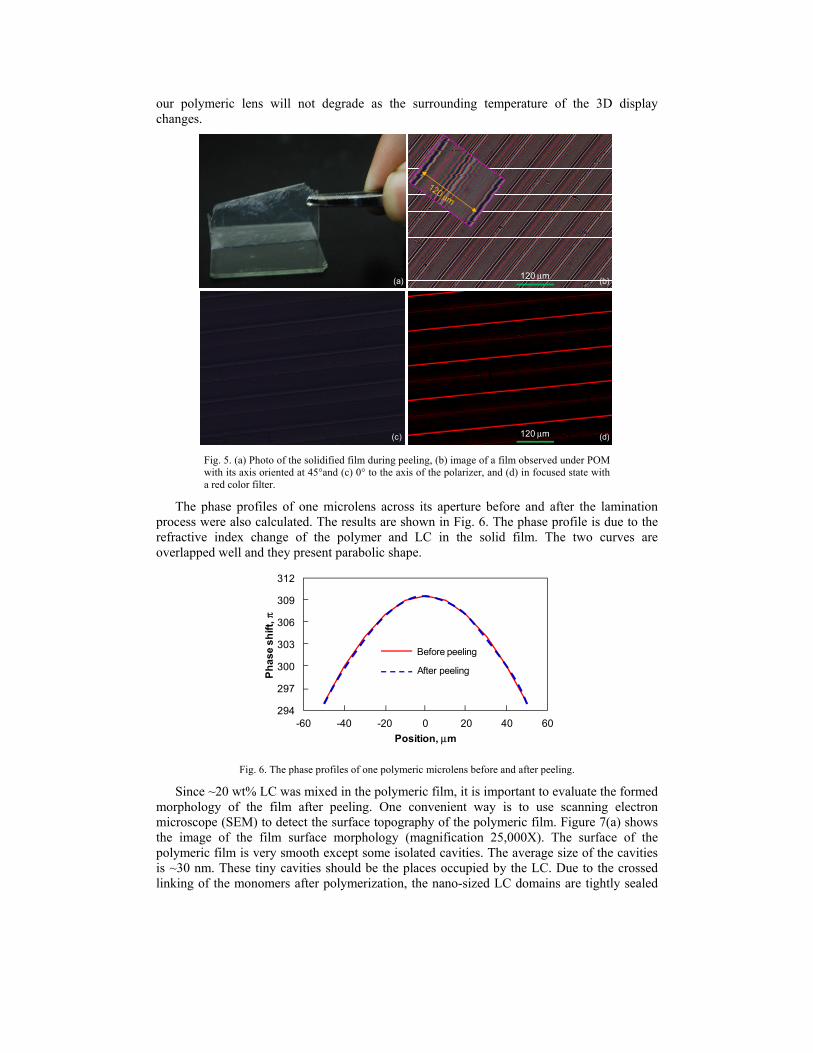
The phase profiles of one microlens across its aperture before and after the lamination process were also calculated. The results are shown in Fig. 6. The phase profile is due to the refractive index change of the polymer and LC in the solid film. The two curves are overlapped well and they present parabolic shape.
294
297
300
303
306
309
312
-60 -40 -20 0 20 40 60
Phas
e sh
ift, π
Position, μm
Before peeling
After peeling
Fig. 6. The phase profiles of one polymeric microlens before and after peeling.
Since ~20 wt% LC was mixed in the polymeric film, it is important to evaluate the formed morphology of the film after peeling. One convenient way is to use scanning electron microscope (SEM) to detect the surface topography of the polymeric film. Figure 7(a) shows the image of the film surface morphology (magnification 25,000X). The surface of the polymeric film is very smooth except some isolated cavities. The average size of the cavities is ~30 nm. These tiny cavities should be the places occupied by the LC. Due to the crossed linking of the monomers after polymerization, the nano-sized LC domains are tightly sealed
#184486 - $15.00 USD Received 30 Jan 2013; revised 26 Feb 2013; accepted 27 Feb 2013; published 25 Mar 2013(C) 2013 OSA 8 April 2013 / Vol. 21, No. 7 / OPTICS EXPRESS 7922
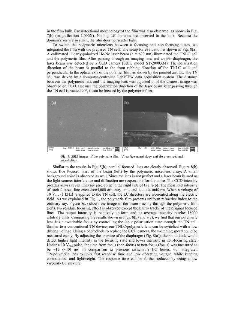
in the film bulk. Cross-sectional morphology of the film was also observed, as shown in Fig. 7(b) (magnification 1,000X). No big LC domains are observed in the bulk. Because the domain sizes are so small, the film does not scatter light.
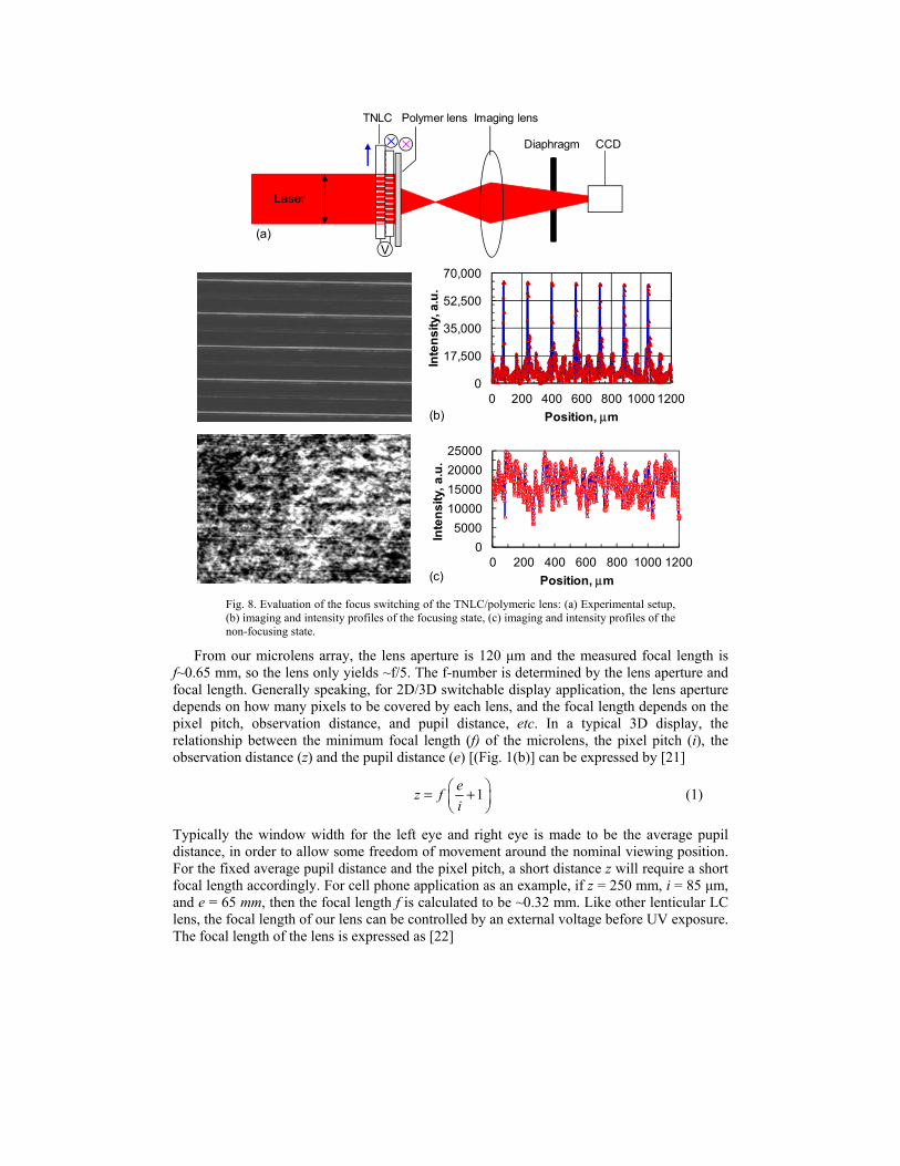
To switch the polymeric microlens between a focusing and non-focusing states, we integrated the film with the prepared TN cell. The setup for evaluation is shown in Fig. 8(a). A collimated linearly-polarized He-Ne laser beam (λ = 633 nm) illuminated the TNLC cell and the polymeric film. After passing through an imaging lens and an iris diaphragm, the laser beam was detected by a CCD camera (SBIG model ST-2000XM). The polarization direction of the beam is parallel to the front rubbing direction of the TNLC cell, and perpendicular to the optical axis of the polymer film, as shown by the pointed arrows. The TN cell was driven by a computer-controlled LabVIEW data acquisition system. The distance between the polymeric lens and the imaging lens was adjusted until the clearest image was observed on CCD. Because the polarization direction of the laser beam after passing through the TN cell is rotated 90°, it can be focused by the polymeric film.
Fig. 7. SEM images of the polymeric film: (a) surface morphology and (b) cross-sectional morphology.
Similar to the results in Fig. 5(b), parallel focused lines are clearly observed. Figure 8(b) shows five focused lines of the beam (left) by the polymeric microlens array. A small background noise is observed as well. Since the lens is not perfect and a laser beam is used as the light source, interference and diffraction are responsible for the noise. The CCD intensity profiles across seven lines are also given in the right side of Fig. 8(b). The measured intensity of each focused line exceeds:64,000 arbitrary units and is quite uniform. When a voltage of 10 Vrms (1 kHz) is applied to the TN cell, the LC directors are reoriented along the electric field. As we explained in Fig. 1, the polymeric film presents uniform refractive index to the ordinary ray. Figure 8(c) shows the image of the beam passing through the polymeric film (left). No residual focusing effect is observed except the blurry tracks of the original focused lines. The output intensity is relatively uniform and its average intensity reaches:18000 arbitrary units. Comparing the results shown in Figs. 8(b) and 8(c), we find that our polymeric lens has a switchable focus by controlling the input polarization state through the TN cell. Similar to a conventional TN device, our TNLC/polymeric lens can be switched with a low driving voltage. Using a photodiode to replace the CCD camera, the switching speed could be measured easily. By adjusting the aperture of the diaphragm (Fig. 8(a)), the photodiode would detect higher light intensity in the focusing state and lower intensity in non-focusing state. Under a 10 Vrms pulse, the time from focus (non-focus) to non-focus (focus) was measured to be ~12 (~40) ms. In comparison to previous switchable LC lenses, our integrated TN/polymeric lens exhibits fast response time and low operating voltage, while keeping compactness and lightweight. The response time can be further reduced by using a low viscosity LC mixture.
#184486 - $15.00 USD Received 30 Jan 2013; revised 26 Feb 2013; accepted 27 Feb 2013; published 25 Mar 2013(C) 2013 OSA 8 April 2013 / Vol. 21, No. 7 / OPTICS EXPRESS 7923
(b)
0
17,500
35,000
52,500
70,000
0 200 400 600 800 1000 1200
Inte
nsity
, a.u
.Position, μm
(c)
0
5000
10000
15000
20000
25000
0 200 400 600 800 1000 1200
Inte
nsity
, a.u
.
Position, μm
TNLC Polymer lens Imaging lens
Laser
Diaphragm CCD
(a)V
× ×
Fig. 8. Evaluation of the focus switching of the TNLC/polymeric lens: (a) Experimental setup, (b) imaging and intensity profiles of the focusing state, (c) imaging and intensity profiles of the non-focusing state.
From our microlens array, the lens aperture is 120 μm and the measured focal length is f~0.65 mm, so the lens only yields ~f/5. The f-number is determined by the lens aperture and focal length. Generally speaking, for 2D/3D switchable display application, the lens aperture depends on how many pixels to be covered by each lens, and the focal length depends on the pixel pitch, observation distance, and pupil distance, etc. In a typical 3D display, the relationship between the minimum focal length (f) of the microlens, the pixel pitch (i), the observation distance (z) and the pupil distance (e) [(Fig. 1(b)] can be expressed by [21]
1e
z fi
= +
(1)
Typically the window width for the left eye and right eye is made to be the average pupil distance, in order to allow some freedom of movement around the nominal viewing position. For the fixed average pupil distance and the pixel pitch, a short distance z will require a short focal length accordingly. For cell phone application as an example, if z = 250 mm, i = 85 μm, and e = 65 mm, then the focal length f is calculated to be ~0.32 mm. Like other lenticular LC lens, the focal length of our lens can be controlled by an external voltage before UV exposure. The focal length of the lens is expressed as [22]
#184486 - $15.00 USD Received 30 Jan 2013; revised 26 Feb 2013; accepted 27 Feb 2013; published 25 Mar 2013(C) 2013 OSA 8 April 2013 / Vol. 21, No. 7 / OPTICS EXPRESS 7924
( )2
f4
wπΔφλ
= (2)
where w is the width of the lenticular lens aperture, Δφ is the phase retardation measured from the lens center and edge, and λ is the light wavelength. For a given w and λ, to get a short focal length we should increase Δφ. To achieve a large Δφ, we could optimize the cell structure in order to generate steep fringing field to create a large gradient refractive index profile.
To get a large size polymeric lenticular microlens array, a flexible substrate is highly desired, since it can be easily peeled off from the solidified polymeric film without any damage. Based on our approach, the polymeric film can be made like a paper; it can be easily installed on a conventional liquid crystal display for 3D imaging or removed for 2D imaging. In this way, the TN cell is no longer required. Our polymeric microlens array allows a switchable 2D/3D displays without the concerns of bulkiness and fragility.
6. Conclusion
We have demonstrated a flat polymeric microlens array for switchable 2D/3D displays. Under a fringing field, a gradient refractive index distribution can be induced within homogeneous aligned LC diacrylate monomers. After UV curing, the monomers form a polymeric film with a lens-like characteristic. The film is optically anisotropic and flexible, and can stand without any substrate. Integrating with a 90° TNLC cell, the lens behavior can be switched between a focusing state and non-focusing state. The entire system is as compact as other switchable LC lenses but has a lower operating voltage and faster response time. The lens performances can be further improved by optimizing the device structure and choosing proper materials. Various flat polymeric lenticular microlenses can be prepared thorough our approach. They are promising for switchable 2D/3D displays applications.
Acknowledgments
H. Ren is supported from the National Research Foundation (NRF) of Korea, the Korea-China Joint Research Program (2012-0004814). The University of Central Florida group is indebted to the U.S. Air Force Office of Scientific Research (AFOSR) for partial financial support under contract No. FA95550-09-1-0170.
#184486 - $15.00 USD Received 30 Jan 2013; revised 26 Feb 2013; accepted 27 Feb 2013; published 25 Mar 2013(C) 2013 OSA 8 April 2013 / Vol. 21, No. 7 / OPTICS EXPRESS 7925