strip stave cores stephanie yang atlas upgrade oxford activities, january 2015
TRANSCRIPT

Strip Stave cores
Stephanie Yang
ATLAS upgrade Oxford activities, January 2015

2
Barrel strip tracker geometry
25/07/2014
Layer No of Staves in 360°
Radii to Centre of Stave
0 28 4051 36 5192 44 6313 56 762
4 (Stub) 64 8625 72 1000
• Total Number of Cylinders: 5• Total Number of Staves: 600
(including stub and no spares)– currently 8 different stave flavours
• Total Number of Modules: 12784– 13 Modules per side of stave = 26
modules per stave– 2 Modules per side of stave for a
stub
3
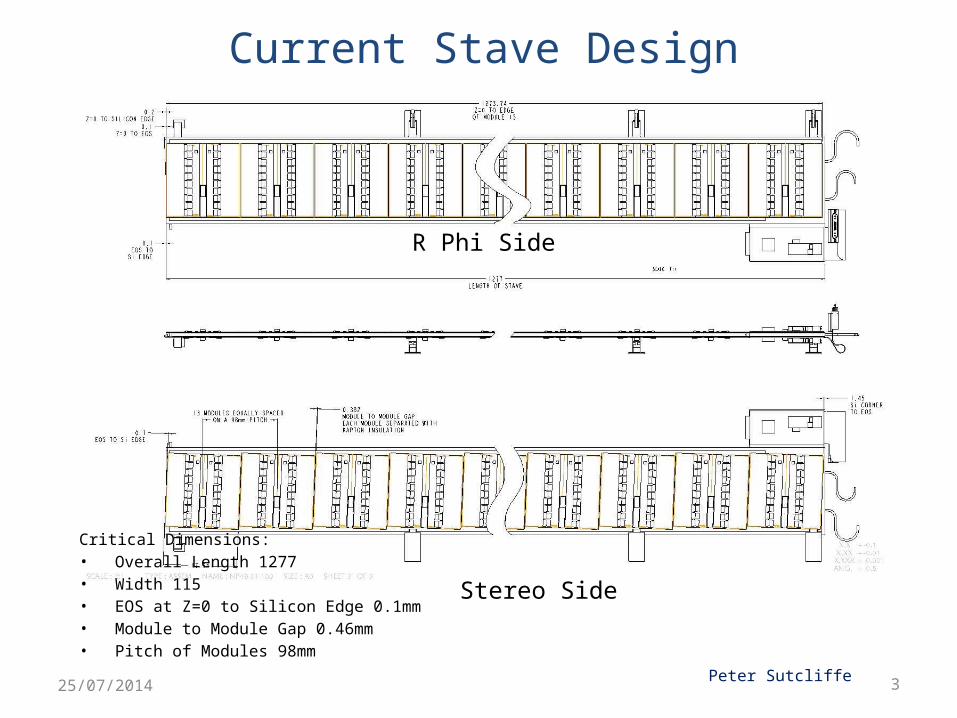
Current Stave Design
Critical Dimensions:• Overall Length 1277• Width 115• EOS at Z=0 to Silicon Edge 0.1mm• Module to Module Gap 0.46mm• Pitch of Modules 98mm
R Phi Side
Stereo Side
Peter Sutcliffe25/07/2014

R-Phi Bus tapeCo-cured to Carbon Skin
EOS Closeout
Cooling Tube Assy
Stereo Bus tapeCo-cured to Carbon Skin
Allcomp foam Cooling strips
Honeycomb core
Carbon C Channels
Allcomp foam End cooling
Z=0 Closeout
Stave components

5
Face sheet co-curing• The Kapton tape and the high
modules carbon fibre co-cured face sheets– 3 layers (0/90/0) of K13C2U(45gsm)/EX1515– Cure at 120°C
• The tooling for this is an Ø10” Al half-section pipe– To compensate for differential thermal
expansion of tape and carbon fibre – A 10mm oversized rim around the tape to
avoid resin bleed and this rim is kept during stave core assembly. It gets milled away at the end of the sandwich production.
Resin bleed
Sacrificial rim

6
Locking points gluing jig
Stave core tooling• Stave core assembly main vacuum jig
– Made of Carbon fibre;– Series dowel holes provide the
positional reference for the sub jigs;
• Main sub jigs are: – Glue masking jig– Foam block alignment jig– C-channel placement jig– Glue bath jig– Locking point gluing jig
Vacuum jig (Liverpool)
C-channel placement jig
Foam blocks and end closeouts
alignment jig

Foam block alignment jig
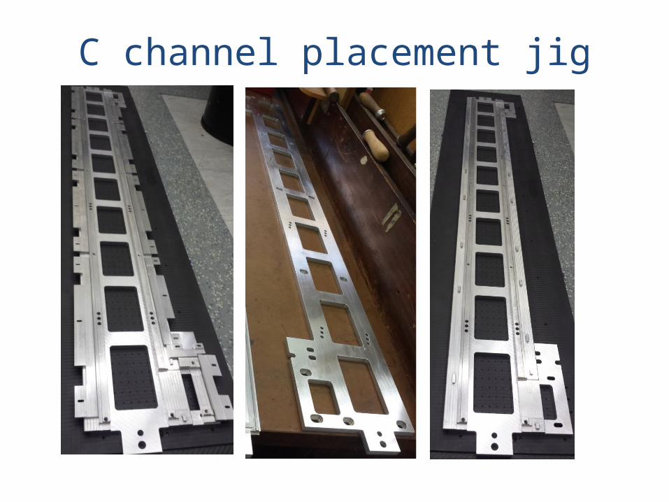
C channel placement jig

9
Step 1: place the face sheet on the main jig(Reference feature: Using dowels at the two ends of the stave centre line to
locate the face sheet to the main jig)
• Two reference fiducial marks /circles of 8mm diameter at the both ends of the over-size region will be added to the tape(Roy will add this feature in his tape design). These marks are used as a template for transferring reference.
• After co-curing the tapes, cut the OD 8mm holes on the face sheet reference to the fiducial marks, a round hole at z=0 end and a slotted hole at z=1.3m end.
• Place the co-cured face sheet onto the assembly jig with the tape side facing down and CF side facing up. Using dowel pins at both ends to locate it.
Prototype of cutting such holes on the co-cured face sheet

10
Step 2: central ruler for masking
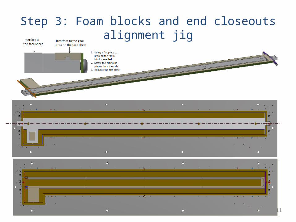
Step 3: Foam blocks and end closeouts alignment jig
11
12
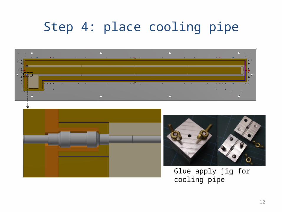
Step 4: place cooling pipe
Glue apply jig for cooling pipe

13
Step 5: C channels placement jig
14
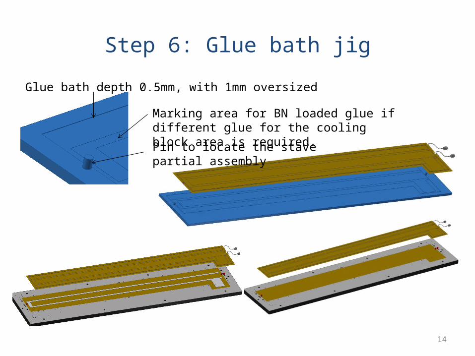
Step 6: Glue bath jig
Glue bath depth 0.5mm, with 1mm oversized
Marking area for BN loaded glue if different glue for the cooling block area is required.
Pin to locate the stave partial assembly
15
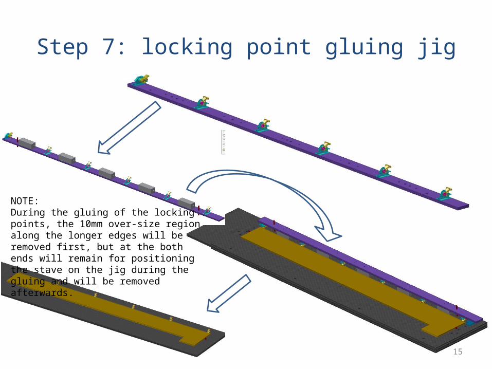
Step 7: locking point gluing jig
NOTE: During the gluing of the locking points, the 10mm over-size region along the longer edges will be removed first, but at the both ends will remain for positioning the stave on the jig during the gluing and will be removed afterwards.

16
Stave production plan
• Liverpool / Oxford are to produce all the tooling sets, and – Each institute will produce a prototype stave using
the given tooling;• Or If tooling is produced at multiple site, then– This must reference to a single source of
engineering drawings. • Finished product will be sent back to a pre-
assigned test centre to check conformity;