state and timing modules for agilent technologies logic analysis
TRANSCRIPT

State and Timing Modules for Agilent TechnologiesLogic Analysis Systems
Product Overview
Your design team faces a difficultchallenge: Deliver quality productsto the marketplace faster thanyour competitors. Meeting thatchallenge depends on your abilityto debug and characterize hard-ware, design and test firmwareand software, and perform systemintegration.
Hardware and software engineersneed a common, scalable systemfor testing and debugging digitalsystems. Agilent Technologiesoffers a variety of measurementmodules for logic analysis systemsto make it easy for you to selectthe right solution today thenexpand as your needs evolve with-out relearning or reinvesting in theplatform.
State/Timing General- 8/16 Bit 32/64 Bit High- Timing Deep trace High- Analysis of dataModules purpose processor processor speed margin capture speed intensive
hardware debug debug or bus analysis or with timing computer systems anddebug channel analysis characterize or state debug performance
intensive setup/hold analysissystems
16710A √ √16711A √ √16712A √ √16557D √ √ √16715A √ √ √16716A √ √ √ √ √16717A √ √ √ √ √16718A √ √ √ √ √ √16719A √ √ √ √ √ √16517/18A √ √
A variety of measurement modules allow you to select the optimum combination of performance, features, and price to meet your specific needs nowand in the future.
Choose the Logic Analyzer and Measurement Modules that Best Fit Your Application
TABLE OF CONTENTSChoose the logic analyzer that best fits your application pg 1Key specifications and characteristics pg 2How to evaluate your logic analysis needs pg 4User interface pg 6VisiTrigger™ pg 72 GHz Timing Zoom pg 8Acquisition memory pg 9Probing pg 10Data processing tools pg 13Supplemental specifications and characteristics pg 15Frame compatibility pg 22Related literature pg 22
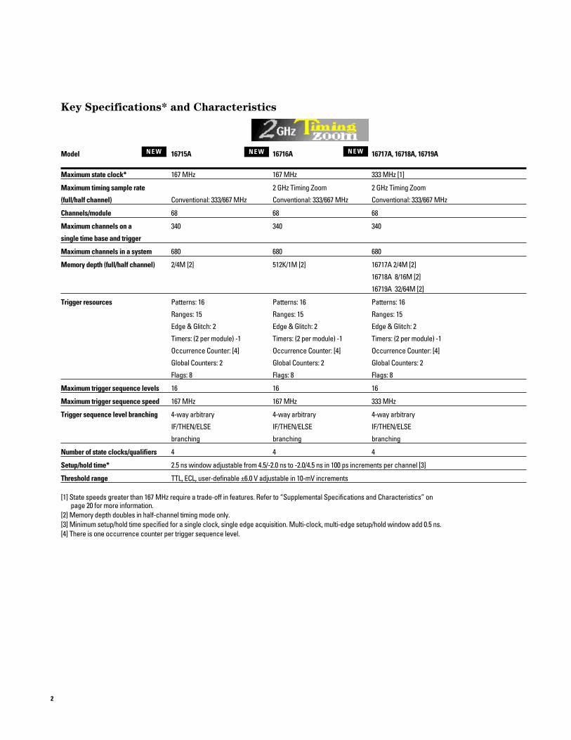
Key Specifications* and Characteristics
Model 16715A 16716A 16717A, 16718A, 16719A
Maximum state clock* 167 MHz 167 MHz 333 MHz [1]
Maximum timing sample rate 2 GHz Timing Zoom 2 GHz Timing Zoom
(full/half channel) Conventional: 333/667 MHz Conventional: 333/667 MHz Conventional: 333/667 MHz
Channels/module 68 68 68
Maximum channels on a 340 340 340
single time base and trigger
Maximum channels in a system 680 680 680
Memory depth (full/half channel) 2/4M [2] 512K/1M [2] 16717A 2/4M [2]
16718A 8/16M [2]
16719A 32/64M [2]
Trigger resources Patterns: 16 Patterns: 16 Patterns: 16
Ranges: 15 Ranges: 15 Ranges: 15
Edge & Glitch: 2 Edge & Glitch: 2 Edge & Glitch: 2
Timers: (2 per module) -1 Timers: (2 per module) -1 Timers: (2 per module) -1
Occurrence Counter: [4] Occurrence Counter: [4] Occurrence Counter: [4]
Global Counters: 2 Global Counters: 2 Global Counters: 2
Flags: 8 Flags: 8 Flags: 8
Maximum trigger sequence levels 16 16 16
Maximum trigger sequence speed 167 MHz 167 MHz 333 MHz
Trigger sequence level branching 4-way arbitrary 4-way arbitrary 4-way arbitrary
IF/THEN/ELSE IF/THEN/ELSE IF/THEN/ELSE
branching branching branching
Number of state clocks/qualifiers 4 4 4
Setup/hold time* 2.5 ns window adjustable from 4.5/-2.0 ns to -2.0/4.5 ns in 100 ps increments per channel [3]
Threshold range TTL, ECL, user-definable ±6.0 V adjustable in 10-mV increments
[1] State speeds greater than 167 MHz require a trade-off in features. Refer to “Supplemental Specifications and Characteristics” on page 20 for more information.
[2] Memory depth doubles in half-channel timing mode only.[3] Minimum setup/hold time specified for a single clock, single edge acquisition. Multi-clock, multi-edge setup/hold window add 0.5 ns.[4] There is one occurrence counter per trigger sequence level.
2
N E W N E W N E W

3
Key Specifications* and Characteristics (cont’d)
Model 16710A, 16711A, 16712A 16557D 16517A/18A1-4 Modules 5 Modules
Maximum state clock* 100 MHz 140 MHz 100 MHz 1 GHz synchronous state [1]
Maximum timing sample rate Conventional: 250/500 MHz Conventional: 250/500 MHz Conventional: 2/4 GHz
(full/half channel) Transitional: 125 MHz
Channels/module 102 68 16
Maximum channel count 204 272 340 80
on a single time base and trigger
Maximum channels in a system 1020 680 160
Memory depth 16710A 8/16K [2] 2/4M [2] 64/128K [2]
(full/half channel) 16711A 32/64K [2]
16712A 128/256K [2]
Trigger resources Patterns: 10 Patterns: 10 Patterns: 4
Ranges: 2 Ranges: 2 Edge & Glitch: 2
Edge & Glitch: 2 Edge & Glitch: 2 Timers:[3]
Timers: 2 Timers: 2
Trigger sequence levels State mode: 12 State mode: 12 State mode: 4
Timing mode: 10 Timing mode: 10 Timing mode: 4
Maximum trigger sequence speed 125 MHz 140 MHz 500 MHz [1]
Trigger sequence level branching Dedicated next state or single arbitrary branching
Number of state clocks/qualifiers 6 4 1[4]
Setup/hold time* 4.0 ns window adjustable from 3.0 ns window adjustable from 700 ps window adjustable from
4.0/0 ns to 0/4.0 ns 3.0/0 ns to -0.5/3.5 ns 350/350 ps adjustable
in 500 ps increments [6] in 500 ps increments [6] in 50 ps increments [5]
per 34 channels per 34 channels per 8 channels
Threshold range TTL, ECL, user-definable ±6.0 V adjustable in 50-mV increments TTL, ECL,
user-definable ± 5 V
adjustable
in 10-mV increments
[1] The Agilent Technologies 16517A, 16518A have a maximum trigger sequencer speed of 500 MHz. Triggering on data at speeds faster than 500 MHz requires the data to be valid for a minimum of 2.25 ns.
[2] Memory depth doubles in half-channel timing mode only.[3] There is one timer or counter per sequence level, which is restarted upon entry into each level.[4] Requires a periodic clock from 20 MHz to 1 GHz. Clock edge is selectable as positive or negative.[5] The setup and hold across pods is 750/750 ps without manual adjustment, 350/350 ps with manual adjustment.[6] Minimum setup/hold time specified for single-clock, single-edge acquisition. Single-clock, multi-edge setup/hold add 0.5 ns.
Multi-clock, multi-edge setup/hold window add 1.0 ns.

4
How to Evaluate Your Logic Analysis Needs
State Speed
State analysis uses a signal fromyour system under test to deter-mine when to sample. Since stateanalysis samples are synchronouswith the system under test, it willprovide you with a view of howyour system is executing. You canuse state analysis to capture buscycles from a microprocessor or I/Obus and convert the data intoprocessor mnemonics or bustransactions using an Agilent Technologies inverse assembler.
Select a state acquisition systemthat provides the speed you needwithout breaking your budget.Remember that a processor willspecify an internal core frequencythat is normally 2X-5X the speed ofthe external bus.
Setup/Hold
Logic analyzers are like any logiccircuitry in that they require timefor the data at the inputs tobecome valid (setup time), andtime to capture the data (holdtime). As your target frequenciesincrease, the ability of your logicanalyzer to capture accurate datais limited by its setup and hold. Alengthy setup and hold can makethe difference between capturingvalid data or data in transition.
Your device under test will ensuredata is valid on the bus for adefined length of time. This isknown as the data valid window.Your target’s data valid window
must be large enough to meet thesetup/hold specifications of thelogic analyzer. The data valid win-dow of most devices is generallyless than half of the clock period.Don’t be fooled by "typical" setupand hold specifications. To ensurethe capture of valid data, the maximum setup/hold time for yourlogic analyzer must fit within yourtarget’s data valid window.
Inaccurate measurements can alsoresult when the logic analyzer’ssetup/hold window cannot be positioned within the target’s datavalid window. An adjustablesetup/hold with fine positionresolution provides unparalleledmeasurement accuracy at high frequencies.
TargetClock
Target DataTarget Data Valid
DataTransitions
Analyzer S/Hmust fit withinthe target's datavalid window
Figure 2. Make sure your logic
analyzer captures accurate data.
Figure 1. State analysis allows you to track real-time system execution problems.

5
Timing Resolution
Timing analysis uses the logic ana-lyzer’s internal clock to determinewhen to sample. Since timinganalysis samples asynchronouslyto the system under test, youshould consider what accuracyyou will need to verify your sys-tem. Accuracy is made up of twoelements: sample speed and chan-nel-to-channel skew. Remember toevaluate both of these elementsand be careful of logic analyzersthat have a fast sample speed witha large channel-to-channel skew.
Transitional Timing
If your system has bursts of activity followed by times withlittle activity, you can use transi-tional timing to capture a longertrace. In transitional timing, theanalyzer samples data at regularintervals, but only stores the datawhen there is a transition on oneof the signals.
Channel Count
Determine the number of signalsyou want to analyze on your sys-tem under test. You will need thisnumber of channels in your logicanalyzer. Even if you have enoughchannels to view all the signals inyour system today, you shouldconsider logic analysis systemsthat allow you to add more chan-nels for your future applicationneeds.
Memory
Deep memory is an invaluableresource when you trigger on aproblem symptom that is farremoved from its cause. This iscommon in complex systems thathave a significant amount of hard-ware/software interaction. Soft-ware engineers will also appreci-ate the ability to capture deeptraces to view code execution.
Much of your debug time is spentanalyzing captured data. Whenusing deep memory,consider alogic analysis system with the performance you need to help youquickly sift through measurementresults.
Triggering
The logic analyzer memory systemis similar to a circular buffer.When the acquisition is started,the analyzer continuously acquiresdata samples and stores them inmemory. When memory becomesfull, it simply wraps around andstores each new sample in theplace of the sample that has beenin memory the longest. This process will continue until
the logic analyzer finds the triggerpoint. The logic analyzer triggerstops the acquisition at the pointyou specify and provides a viewinto the system under test. The pri-mary responsibility of the trigger isto stop the acquisition, but it canalso be used to control the selec-tive storage of data. Consider alogic analyzer with the triggerresources you need to quickly setup your measurements.
Figure 3. Evaluate time relationships between signals with timing analysis.

6
Improve your Productivity with an Intuitive User Interface
Measurement configuration and data files canbe loaded directly into the logic analyzer
Menu tabs provide a logical progression through the setup of your measurement.
State and timing mode selectionsspecify how data is sampled.
Single location for access to all state acquisition options.
Convenient color coding helps youidentify the signals in the interfacewith the physical connection to your device under test.
Clocking for state measurements can be quickly defined using the clock setup menu.
Sampling defines how the logicanalyzer will acquire the data.
Figure 4. Setting up your logic analyzer has never been this easy to understand.
Format allows youto group signals into buses.
Trigger defines whatdata is acquired.
You may not use your logic analyzer every day, therefore Agi-lent Technologies has made theuser interface easy to understand.Now you can spend more timemaking measurements and lesstime setting up the logic analyzer.
Timing Zoom sample rate and positionconfigured relative to the triggerof the main analyzer.

7
Agilent Technologies’ New VisiTrigger™ Technology Allows You To Quickly LocateYour Most Elusive Problems
Your most commonly used triggers are just amouse click away with the built-in triggerfunctions. VisiTrigger’s graphical representa-tion shows you how the trigger condition will be defined. You can use triggerfunctions as building blocks to easily customize a trigger for your specific task.
Sequence levels allow you to develop a sequence of analyzer instructions to specify a trigger point or to qualify data and store onlythe information that interests you. Each step inthe sequence contains an "IF/THEN/ELSE"structure that can evaluate up to four logicevents. Each event can specify a combinationof actions such as: store sample, incrementcounters, reset timers, trigger, or go to anotherstep in the sequence level.
Ranges provide a way to monitor programand data accesses within a specified areain memory.
Global counters can count events such as the number of times a function executes oraccesses an I/O port.
Timers can be set up to evaluate when oneevent happens too late or too soon with respect to another event.
In timing mode, edge terms let you trigger on a rising edge, falling edge, either edge, or a glitch.
Patterns and their logical combinationslet you identify which states to store, when tobranch and when to trigger.
Save and recall up to ten of your custom trigger setups without loadinga new configuration file.
View up-to-date information on thecurrent state of the timers, counters, flags, andthe trigger sequence level.
Flags can be set, cleared and evaluated byany 16715/16/17/18/19A module in the frame.This allows you to set up a trigger that is depen-dent on activity from more than one bus in thesystem.
Values can be easily entered directly into thetrigger description.
Figure 5. Set up your trigger in
terms of the measurements you
want to make.
VisiTrigger™ technology availablein the 16715A, 16716A, 16717A,16718A, and 16719A family of mod-ules is a breakthrough in logicanalysis usability. It combinesincreased trigger functionalitywith a user interface that is easy to
understand and use. Now with VisiTrigger™, capturing complexevents is as simple as point-and-click to choose the trigger functionand fill-in-the-blank to customize itto your specific task.

8
The 16716A, 16717A, 16718A, and16719A state/timing modules provide a breakthrough in logicanalysis performance by allowingyou to acquire up to 2 GHz timingand high-speed state data simulta-neously through the same connec-tion to your device under test.
2 GHz Timing Zoom Provides High-Speed Timing Analysis Across AllChannels, All the Time
2 GHz Timing Zoom provides superior flexibility in high-speeddata capture with a variable sam-ple rate from 250 MHz to 2 GHz,16K memory depth, and variableplacement of Timing Zoom dataaround the trigger point.
With Timing Zoom’s 500 ps resolu-tion, you can now use the widechannel count of a logic analyzerto improve the efficiency of yourhardware characterizationprocess.
Figure 6. Verifying critical edge timing in your system just got easier
with Agilent Technologies' 2 GHz Timing Zoom technology.
Use the globalmarkers totime-correlate eventsacross multipledisplays.
Now the ability to capture simultaneous 2 GHz timing and high-speed state information is as effortless as clicking on the run button.
Timing Zoom labels are automatically created andmarked with an _TZ extension.

9
Memory depth can be an invalu-able resource when you are tryingto link the symptom of a problemto its root cause. Extensive acqui-sition memory allows you to viewlong periods of code execution,capture deep traces of timinginformation, optimize your systemfor peak performance, or validateyour ASIC design against EDA sim-ulations.
Usable Deep MemoryThe key to deep memory is systemperformance. The 16718A and16719A modules include the fol-lowing innovative hardwareenhancements to improve the per-formance and usability of largedata sets:
Insure the Capture of Difficult to Reproduce System Problems
Figure 7. Agilent Technologies offers a variety of memory depths to fit your
price/performance needs
• Hardware Accelerated Search
Even if the pattern you specify isnot found in the entire 32M trace, the search takes only a few seconds.
• Fast Waveform Draw
The entire 32M waveform can bedrawn on screen in a matter of seconds, then you can draw a boxaround an area and quickly zoom in to explore the details.
• Fast Binary Out
The ability for you to quickly remove data from the logic analyzer has also been optimized.
• Constant Feedback with
Cancel
You are provided with feedback on percent to completion of the operation, and you have the option to cancel it at any time.
Note: Some Agilent Technologiestools are limited to a maximummemory depth of 2M because theycreate multiple large data records.These tools are: Compare, B4601Bserial analysis tool set, B4605Btool development kit.
Deep memory traces create largedata files when you save theacquired data. For this reason,option #008 has been added to the16700A-Series mainframes to pro-vide an 18 GB external hard drive.This option is recommended whenyou use the 16718A and 16719Amodules.

10
For more information refer to “Processor andBus Support for Agilent Technologies LogicAnalyzers.”
Figure 8. A rugged connection lets you capture accurate data; inverse assemblers
help you make sense of it.
Why is Probing Important?
Your debugging tools performthree important tasks: probingyour target system, acquiring data,and analyzing data. Data acquisi-tion and analysis tools are only aseffective as the physical interfaceto your target system. Use the fol-lowing criteria to see how yourprobing measures up.
Immunity to Noise
EMF noise is everywhere, and itcan corrupt your data. Activeattenuator probing can be particu-larly susceptible to noise effects.Agilent Technologies designsprobing solutions with high immunity to transient noise.
Impedance
High input impedance will minimize the effect of probing onyour circuit. Although manyprobes are acceptable for lowerfrequencies, probing effectsbecome very significant at higher frequencies.
Ruggedness
A flimsy probe will give you unintended open circuits, addingone more variable to your debug-ging equation. Agilent Technolo-gies’ probes are mechanicallydesigned to relieve strain andensure a rugged andreliable connection.
Connectivity
A multitude of packages exist inthe digital electronics industry.Check our large selection of probing solutions designed forspecific chip packages or buses.As an alternative, we offer reliabletermination adapters that workwith standard on-target connec-tors.

11
Probing your device under testis potentially one of the most dif-ficult and certainly one of themost important tasks in debug-ging your digital design. That iswhy Agilent Technologies pro-vides a wider variety of probing solutions than anyone else in theindustry—each with a differentset of advantages particular to agiven situation. We like to thinkof it as helping you get your sig-nals off to a great start.
Choose the Probing Technique That Best FitsYour Application
Probing Alternative Advantages Limitations_________________________________________________________________________________General-Purpose Most flexible method. Works in Can be cumbersome Lead Sets and Surface conjunction with SMD clips and Wedge when connectingMount IC Clips adapters listed below. Included with a large number(Figure 9 and 10) logic analyzer purchase. of channels._________________________________________________________________________________Ultra-Fine Pitch Surface Smallest IC clips in the industry to date Same as above plus Mount Device Clips (down to 0.5 mm). Works with both logic small incremental cost.(Figure 11) analyzer and scope probing systems._________________________________________________________________________________Wedge Probe Adapter Compressible dual conductors between Same as above plus for QFP Packages adjacent IC legs make 3-16 adjacent signal small incremental cost.(Figure 12) leads available to logic analyzer and
scope probing systems._________________________________________________________________________________Elastomeric Provides access to all signal leads for Requires minimal Solutions for Generic generic QFP packages (including custom keep out area.QFP Packages ICs). Uses combination of one probe Moderate (Figure 13) adapter and four flexible adapters, plus incremental cost.
general-purpose lead sets._________________________________________________________________________________Direct Connection to Very reliable and convenient probing Requires advanceDevice Under Test via system when frequent probing planning to integrateBuilt-In Connectors connections are required (manufacturing into design process. (Figure 14 and 15) or field test for example). Connectors Moderate
can be located at optimal position in incremental cost.the device under test. Can work in conjunction with Agilent Technologiesinverse assemblers.
_____________________________________________________________________________Analysis Probes Support for over 200 different Requires moderate for Specific Processors processors and buses. Includes clearance around and Buses reliable logic analyzer probe processor or bus. (Figure 8) pod connectors, logic analyzer Moderate to significant
configuration files and device- extra cost depending onspecific inverse assemblers. specific processor or
bus.
Figure 9. General-purpose probing
solution
Figure 10. Surface mount IC clips
Figure 11. Ultra-fine pitch surface
mount device clips
Figure 12. Agilent Wedge Probe Adapters
for QFP package
Agilent Wedge Probe AdapterIC leg spacing Number of signals Number of wedges in pack Model number0.5 mm 3 1 E2613A0.5 mm 3 2 E2613B0.5 mm 8 1 E2614A0.5 mm 16 1 E2643A0.65 mm 3 1 E2615A0.65 mm 3 2 E2615B0.65 mm 8 1 E2616A0.65 mm 16 1 E2644A

Agilent Probing SolutionsPackage type Pin Pitch Elastomeric Solutions
240-pin PQFP/CQFP 0.5 mm E5363A probe adapter
E5371A 1/4-flexible adapter 208-pin PQFP/CQFP 0.5 mm E5374A probe adapter
E5371A 1/4-flexible adapter176-pin PQFP 0.5 mm E5348A probe adapter
E5349A 1/4-flexible adapter160-pin QFP 0.5 mm E5377A probe adapter
E5349A 1/4-flexible adapter160-pin PQFP/CQFP 0.65 mm E5373A probe adapter
E5349A 1/4-flexible adapter 144-pin PQFP/CQFP 0.65 mm E5361A probe adapter
E5340A 1/4-flexible adapter144-pin TQFP 0.5 mm E5336A probe adapter
E5340A 1/4 flexible adapter
Figure 13. Elastomeric probing solution
Figure 14. High-density direct
connection solution
Figure 15. Normal-density direct
connection solution
Agilent E5346Ahigh-densityadapter cables
Probe cablesfrom logicanalyzer
Terminationadapter (Agilentpart number01650-63203)
20-pin connector(Agilent part number1251-8106 2 x 10 pinheader with 0.1” x0.1” spacing)
Probe cablesfrom logicanalyzer
Internal RCnetworks
Optional shroud(Agilent part numberE5346-44701)
Mictor (Agilentpart numberE5346-68701)
For more information refer to “Probing Solutionsfor Agilent Technologies Logic Analysis Systems.”
12

13
Examine Your Prototype’sBehavior from All Angles
Causes and symptoms to problems often manifest them-selves in different domains. Cross-module triggering and timecorrelation between state, timing,and analog measurements helpyou quickly gain insight to solveyour tough hardware and softwareintegration problems.
Track Problems in Multiproces-
sor Systems or Between a
Processor and an Interface Bus
Configure any Agilent Technolo-gies 1655X or 1671X Series moduleas two independent state analyzersthat sample data using separateclocks. Then, view both time-cor-related state listings together onthe same screen.
Determine Whether
the Problem is in
Hardware or Software
Use our 2 GHz Timing Zoom tocapture system behavior betweenstates. Display both the state list-ing and Timing Zoom waveformand use the time-correlated mark-ers to identify the cause of prob-lem states.
Verify the Analog Behavior
of a Signal at a Critical Time
Trigger the Agilent Technologies16533A or 16534A digitizing oscil-loscope from either the state ortiming analyzer. Observe relation-ships among all three time-corre-lated measurements.
Figure 16. You can quickly isolate the root cause of system problems by examin-
ing target operation across a wide analysis domain, from analog signals to source
code.
Debug Your Source Code
Now you can view high-levelsource code, time-correlated withthe real-time logic analyzer trace,to provide a view into how thesoftware actually executed in thesystem under test. The AgilentTechnologies B4620B source cor-relation tool set links the logicanalyzer trace with the sourcecode that produced it.
Profile Your System’s
Performance
An optimized digital systemrequires a balance of hardwareand software performance. TheAgilent Technologies B4600B system performance analysis toolset allows you to profile yourentire system to clearly identifybottlenecks in the hardware orsoftware.

14
State/timing State/timing State Timing State/timing State TimingModel listing waveform chart chart distribution compare compare
16500C √ √ √ √16700A, 16702A √ √ √ √ √ √ √
A ‘√’ indicates that the measurement is supported in the frame.
Display Options Supported in Agilent Technologies Logic Analysis Mainframes
Analyze Target
Operation with a
Variety of Display Options
The Agilent Technologies logicanalysis systems allow you to ana-lyze target operation from different perspectives to help youidentify problems quickly. In addition to the traditional statelisting and timing waveform displays, you can view your dataas a chart or a distribution overtime.
Tools such as compare provideyou with the ability to perform abit-by-bit comparison betweennewly acquired data and a refer-ence trace from a known workingsystem. This quickly points you toany differences that are occurringbetween the two systems.
Figure 17. Verify A/D performance or track code flow
graphically using the chart display.
Figure 18. Analyze system performance to uncover bottle-
necks in your hardware or software.

15
1.5pF
370 ohms
7.4pF
GROUND
100Kohm
Figure 19. Equivalent probe load for
the Agilent 16557D, 16710A, 16711A,
and 16712A, general-purpose lead set.
Agilent Technologies 16557D, 16710A, 16711A, 16712A Supplemental Specifications* and Characteristics
Probes (general-purpose lead set)
Input resistance 100 KΩ, ±2%
Parasitic tip capacitance 1.5 pF
Minimum voltage swing 500 mV, peak-to-peak
Threshold accuracy* ±(100 mV + 3% of threshold setting)
Maximum input voltage ±40 V peak
State Analysis
Minimum state clock pulse width 3.5 ns
Time tag resolution [1] 8 ns
Maximum time count 34 seconds
between states
Maximum state tag 4.29 x 10 9 states
count between states [1]
Minimum master to 16710A, 16711A, 16712A: 10 ns
master clock time* 16557D: 7.14 ns Minimum master to slave clock time 0.0 nsMinimum slave to master clock time 4.0 nsContext storeblock sizes [2] 16, 32, 64 states
Timing Analysis
Sample period accuracy 0.01% of sample period
Channel-to-channel skew 2 ns, typical
Time interval accuracy ± (sample period + channel-to-channel
skew + 0.01% of time interval reading)
Minimum detectable glitch 3.5 ns
Triggering
Maximum trigger sequence speed 125 MHz, maximum (Agilent 16710A/11A/12A)
140 MHz, maximum (Agilent 16557D)
Maximum occurrence counter 1,048,575
Range width 32 bits each
Timer value range 400 ns to 500 seconds
Timer resolution 16 ns or 0.1% whichever is greater
Timer accuracy ±32 ns or ±0.1% whichever is greater
Operating Environment
Temperature Agilent 16600A series frame: Instrument, 0˚C to 40˚ C (+32˚F to 104˚F)
Agilent 16700A series frame: Instrument 0˚C to 50˚C (+32˚F to 122˚F)
Probe lead sets and cables, 0˚C to 65˚C (+32˚F to 149˚F)
Humidity 80% relative humidity at +40˚ CAltitude Operating 4600m (15,000ft)
Nonoperating 15,300m (50,000ft)
[1] Time or state tags halve the acquisition memory when there are no unassigned pods.[2] Only available with the Agilent 16710A , 16711A and 16712A modules.

16
Agilent Technologies 16517A/18A Supplemental Specifications* and Characteristics
Probes
Input dc resistance 100 KΩ, ±2%
Input impedance dc thru 400 ns rise time, 100 KΩ typical
3.5 ns thru 350 ps, 500 Ω typical
Input capacitance 0.2 pF and then, through 500 Ω, 3 pF
Minimum voltage swing* 500 mV, peak-to-peak
Threshold accuracy* ±2% of input signal ±50 mV
Minimum input overdrive 250 mV or 30% of input (whichever is
greater above the pod threshold)
Input dynamic range ±5 V above the threshold
Maximum input voltage 40 V peak-to-peak
Synchronous State Analysis
Minimum external clock period* 1 ns
Minimum state speed 20 MHz, requires a periodic clock
Minimum detectable pulse width 900 psChannel-to-channel skew Per pod: 250 ps, typical
Across pods: 1 ns, typical 250 ps, with manual adjustment
State clock duty cycle range 1 GHz thru 500 MHz: 45% - 55%, typical500 MHz thru 250 MHz: 30% - 70%, typical250 MHz thru 20 MHz: 20% - 80%, typical
Oversampling 2x, 4x, 8x, 16x, and 32x with a maximum rate of 2 GHz
Timing Analysis
Minimum detectable pulse width 4 GHz: 800 ps, typical2 GHz or less: 1.1 ns, typical
Sample period accuracy 0.005% of sample period
Channel-to-channel skew 250 ps across all channels, typical
Time interval accuracy ± (sample period + channel-to-channel
skew + 0.005% of time interval reading)
Trigger Characteristics
Maximum sequencer speed 500 MHz
Maximum occurrence count 16,777,216
Minimum pattern recognizer 2.25 ns
pulse width
Edge counting frequency 444 MHz
Edge detection Up to 1 GHz
Greater than duration (timing only) 0 ns to 510 ns range, accuracy is ±2.25 ns
Less than duration (timing only) 4 ns to 510 ns range, accuracy is ±2.25 nsTimer/counter range Timing mode: 0 s to 33 ms
State mode: 500 MHz to 1 GHz, (user clock period) x (223)Below 500 MHz, (user clock period) x (224)
Timer resolution Timing mode: 2 nsState mode: Above 500 MHz, 2 x (user clock period)
Below 500 MHz, user clock periodTimer accuracy 0.005% of timer value
500 ohms
3pF0.2pF
GROUND
100Kohm
Figure 20. Equivalent probe load for
the Agilent 16517A/18A.

17
Agilent Technologies 16715A, 16716A, 16717A, 16718A,16719A Supplemental Specifications* and Characteristics
Probes (general-purpose lead set)
Input resistance 100 KΩ, ± 2%
Parasitic tip capacitance 1.5 pF
Minimum voltage swing 500 mV, peak-to-peak
Minimum input overdrive 250 mV
Threshold range -6V to +6V in 10 mV increments
Threshold accuracy* ± (65 mV + 1.5% of settings)
Input dynamic range ± 10V about threshold
Maximum input voltage ± 40V peak
+5V Accessory current 1/3 amp maximum per podChannel assignment Each group of 34 channels can be assigned to
Analyzer 1, Analyzer 2 or remain unassigned
2 GHz Timing Zoom (Agilent 16716A, 16717A, 16718A, 16719A only)
Timing analysis sample rate 2 GHz/1 GHz/500 MHz/250 MHz
Sample period accuracy ± 50 ps
Channel-to-channel skew < 1.0 ns
Time interval accuracy ± (sample period + channel-to-channel skew + 0.01% of time
interval reading)
Memory depth 16 K
Trigger position Start, center, end, or user defined
Operating Environment
Temperature Agilent 16700A Series frame: 0˚C to 50˚C (+32˚F to 122˚F)
Probe lead sets and cables: 0˚C to 65˚C (+32˚F to 149˚F)
Humidity 80% relative humidity at + 40˚C
Altitude Operating 4600 m (15,000 ft)
Non-operating 15,300 m (50,000 ft)
1.5pF
370 ohms
7.4pF
GROUND
100Kohm
Figure 21. Equivalent probe load for
the Agilent 16715A, 16716A, 16717A,
16718A, 16719A general-purpose
lead set.

18
Agilent Technologies 16715A, 16716A, 16717A,16718A, 16719A Supplemental Specifications* andCharacteristics (cont’d)
167 MHz State Mode
Maximum state speed* 167 MHz
Channel count 68 per moduleMaximum channels on a singletime base and trigger 340Number of independent analyzers 2, can be setup in state or timing modesMinimum master to master clock time* [1] 5.988 nsMinimum master to slave clock time 2 nsMinimum slave to master clock time 2 nsMinimum slave to slave clock time 5.988 ns Setup/hold time* [1] 2.5 ns window adjustable from (single-clock, single-edge) 4.5/-2.0 ns to -2.0/4.5 ns in 100 ps increments
per channelSetup/hold time* [1] 3.0 ns window adjustable from(multi-clock, multi-edge) 5.0/-2.0 ns to -1.5/4.5 ns in 100 ps increments
per channelSetup/hold time (with manual adjustment) 1.0 ns windowMinimum state clock pulse width 1.2 nsTime tag resolution [2] 4 nsMaximum time count between states 17 secondsMaximum state tag count 232
between states [2]Number of state clocks/qualifiers 4Maximum memory depth 16716A: 512K
16715A, 16717A: 2M16718A: 8M16719A: 32M
Maximum trigger sequence speed 167 MHzMaximum trigger sequence levels 16Trigger sequence level branching 4 way arbitrary “IF/THEN/ELSE” branchingTrigger position Start, center, end, or user defined

19
Agilent Technologies 16715A, 16716A, 16717A,16718A, 16719A Supplemental Specifications* andCharacteristics (cont’d)
167 MHz State Mode (cont’d)
Trigger resources 16 Patterns evaluated as =, ≠, >, <, ≥, ≤15 Ranges evaluated as in range, not in range(2 Timers per module) -12 Global counters1 Occurrence counter per sequence level8 Flags
Trigger resource conditions Arbitrary boolean combinationsTrigger actions Goto
Trigger and fill memoryTrigger and gotoStore/don’t store sampleTurn on/off default storingTimer start/stop/pause/resumeGlobal counter increment/resetOccurrence counter resetFlag set/clear
Store qualification Default and per sequence levelMaximum global counter 16,777,215Maximum occurrence counter 16,777,215Maximum pattern/range width 32 bitsTimers value range 100 ns to 5497 secondsTimer resolution 5 nsTimer accuracy 10 ns + .01%Timer reset latency 70 nsData in to trigger out (BNC port) 150 ns, typicalFlag set/reset to evaluation 110 ns, typical

20
Agilent Technologies 16715A, 16716A, 16717A,16718A, 16719A Supplemental Specifications* andCharacteristics (cont’d)
333 MHz State Mode (Agilent 16717A, 16718A, 16719A only)
Maximum state speed* 333 MHz
Channel count (Number of modules x 68) - 34Maximum channels on a single 306time base and triggerNumber of independent analyzers 1, when 333 MHz state mode is selected
the second analyzer is turned offMinimum master to master 3.003 nsclock time* [1]Setup/hold time* [1] 2.5 ns window adjustable from(single-clock, single-edge) 4.5/-2.0 ns to-2.0/4.5 ns in 100 ps increments
per channelSetup/hold time* [1] 3.0 ns window adjustable from(single-clock, multi-edge) 5.0/-2.0 ns to -1.5/4.5 ns in 100 ps increments
per channel
Setup/hold time (with manual adjustment) 1.0 ns window
Minimum state clock pulse width 1.2 ns
Time tag resolution [2] 4 ns
Maximum time count between states 17 seconds
Number of state clocks 1
Maximum memory depth 16717A: 2M
16718A: 8M
16719A: 32M
Maximum trigger sequence speed 333 MHz
Maximum trigger sequence levels 15
Trigger sequence level branching Dedicated next state branch or reset
Trigger position Start, center, end, or user defined
Trigger resources 8 Patterns evaluated as =, ≠, >, <, ≥, ≤4 Ranges evaluated as in range, not in range2 Occurrence counters8 Flags
Trigger resource conditions Arbitrary boolean combinationsTrigger actions Goto
Trigger and fill memory
Store qualification Default
Maximum occurrence counter 16,777,215
Maximum pattern/range width 32 bits
Data in to trigger out (BNC port) 150 ns, typical
Flag set/reset to evaluation 110 ns, typical

21
Agilent Technologies 16715A, 16716A, 16717A,16718A, 16719A Supplemental Specifications* andCharacteristics (cont’d)
Timing Mode
Timing analysis sample rate 333/667 MHz(full/half channel)
Channel count 68 per module
Maximum channels on
a single time base and trigger 340
Number of independent analyzers 2, can be setup in state or timing modes
Sample period (full channel) 3 ns to 1 ms
Sample period (half channel) 1.5 ns
Sample period accuracy ±(100 ps + .01% of sample period)
Channel-to-channel skew < 1.5 ns
Time interval accuracy ± (sample period + channel-to-channel
skew + .01% of time interval reading)
Minimum detectable glitch 1.5 nsMemory depth (full/half channel) 16716A: 512K/1M
16715A, 16717A: 2/4M16718A: 8/16M16719A: 32/64M
Maximum trigger sequence speed 167 MHz
Maximum trigger sequence levels 16
Trigger sequence level branching 4 way arbitrary “IF/THEN/ELSE” branchingTrigger position Start, center, end, or user definedTrigger resources 16 Patterns evaluated as =, ≠, >, <, ≥, ≤
15 Ranges evaluated as in range, not in range2 Edge/glitch(2 Timers per module) -12 Global counters1 Occurrence counter per sequence level8 Flags
Trigger resource conditions Arbitrary boolean combinationsTrigger actions Goto
Trigger and fill memoryTrigger and gotoTimer start/stop/pause/resumeGlobal counter increment/resetOccurrence counter resetFlag set/clear
Maximum global counter 16,777,215
Maximum occurrence counter 16,777,215
Maximum pattern/range width 32 bits
Timer value range 100 ns to 5497 seconds
Timer resolution 5 ns
Timer accuracy ±10 ns + .01%
Greater than duration 6 ns to 100 ms in 6 ns increments
Less than duration 12 ns to 100 ms in 6 ns increments
Timer reset latency 70 ns
Data in to trigger out (BNC port) 150 ns, typical
Flag set/reset to evaluation 110 ns, typical
[1] Specified for an input signal VH=-0.9V, VL=-1.7V, Slew rate=1V/ns, and threshold=-1.3V.[2] Time or state tags halve the acquisition memory when there are no unassigned pods.
22
Product WarrantyAgilent Technologies hardware productsare warranted against defects in materialsand workmanship for a period of one yearfrom date of shipment. Some newly manufactured Agilent Technologies product may contain remanufactured parts,which are equivalent to new in performance. If you send notice of defectsduring the warranty period, Agilent willeither repair or replace hardware productsthat prove defective.
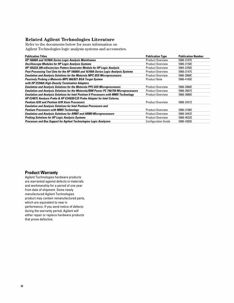
Publication Titles Publication Type Publication NumberHP 16600A and 16700A Series Logic Analysis Mainframes Product Overview 5966-3107EOscilloscope Modules for HP Logic Analysis Systems Product Overview 5966-3150EHP 16522A 200 mVector/sec Pattern Generator Module for HP Logic Analysis Product Overview 5964-2250EPost Processing Tool Sets for the HP 16600A and 16700A Series Logic Analysis Systems Product Overview 5966-3147EEmulation and Analysis Solutions for the Motorola MPC 8XX Microprocessors Product Overview 5966-2866EPassively Probing a Motorola MPC 860/821 BGA Target System Product Note 5966-4165Ewith HP E5346A High-Density Termination AdaptersEmulation and Analysis Solutions for the Motorola PPC 6XX Microprocessors Product Overview 5966-2868EEmulation and Analysis Solutions for the Motorola/IBM Power PC 740/750 Microprocessors Product Overview 5966-2867EEmulation and Analysis Solutions for Intel Pentium II Processors with MMX Technology Product Overview 5966-3880EHP E2487C Analysis Probe & HP E2492B/C/D Probe Adapter for Intel Celeron,Pentium II/III and Pentium II/III Xeon Processors Product Overview 5968-2421EEmulation and Analysis Solutions for Intel Pentium Processors andPentium Processors with MMX Technology Product Overview 5966-3106EEmulation and Analysis Solutions for ARM7 and ARM9 Microprocessors Product Overview 5966-3442EProbing Solutions for HP Logic Analysis Systems Product Overview 5968-4632EProcessor and Bus Support for Agilent Technologies Logic Analyzers Configuration Guide 5966-4365E
Related Agilent Technologies LiteratureRefer to the documents below for more information on Agilent Technologies logic analysis systems and accessories.

For more information about Agilent Technolo-gies test and measurement products, applica-tions, services, and for a current sales officelisting, visit our web site:http://www.agilent.com/find/tmdir
You can also contact one of the following cen-ters and ask for a test and measurement salesrepresentative.
United States: Agilent Technologies Test and Measurement Call CenterP.O. Box 4026Englewood, CO 80155-4026 (tel) 1 800 452 4844
Canada:Agilent Technologies Canada Inc.5150 Spectrum WayMississauga, OntarioL4W 5G1(tel) 1 877 894 4414
Europe:Agilent TechnologiesTest & MeasurementEuropean Marketing OrganisationP.O. Box 9991180 AZ AmstelveenThe Netherlands(tel) (31 20) 547 9999
Japan:Agilent Technologies Japan Ltd.Call Center9-1, Takakura-Cho, Hachioji-Shi,Tokyo 192-8510, Japan(tel) (81) 426 56 7832(fax) (81) 426 56 7840
Latin America:Agilent TechnologiesLatin American Region Headquarters5200 Blue Lagoon Drive, Suite #950Miami, Florida 33126U.S.A.(tel) (305) 267 4245(fax) (305) 267 4286
Australia/New Zealand:Agilent Technologies Australia Pty Ltd 347 Burwood HighwayForest Hill, Victoria 3131(tel) 1-800 629 485 (Australia)(fax) (61 3) 9272 0749(tel) 0 800 738 378 (New Zealand)(fax) (64 4) 802 6881
Asia Pacific:Agilent Technologies24/F, Cityplaza One, 1111 King’s Road,Taikoo Shing, Hong Kong tel: (852)-3197-7777fax: (852)-2506-9284
Technical data is subject to change
Printed in U.S.A. 01-005966-3367E
Ordering Information www.agilent .com
State and Timing Module Logic Analysis System Frame
16500C, 16700A,16501A 16701A, 16702A
16517A , 16518A √ √16557D √ √16710A √16711A √16712A √16715A √16716A √16717A √16718A √16719A √
A ‘√’ = indicates the module is supported in the frame.