agilent 1200 series handheld control module · 1200 series handheld control module users’s guide...
TRANSCRIPT
Agilent 1200 Series Handheld Control Module
User’s Guide
A
1200 Series Handheld Control Module Users’s Guide
Notices© Agilent Technologies, Inc. 2000-2006
No part of this manual may be reproduced in any form or by any means (including elec-tronic storage and retrieval or translation into a foreign language) without prior agree-ment and written consent from Agilent Technologies, Inc. as governed by United States and international copyright laws.
Microsoft ® - Microsoft is a U.S. registered trademark of Microsoft Corporation.
Manual Part NumberG1323-90010
Edition02/2006
Printed in Germany
Agilent TechnologiesHewlett-Packard-Strasse 8 76337 Waldbronn, Germany
WarrantyThe material contained in this docu-ment is provided “as is,” and is sub-ject to being changed, without notice, in future editions. Further, to the max-imum extent permitted by applicable law, Agilent disclaims all warranties, either express or implied, with regard to this manual and any information contained herein, including but not limited to the implied warranties of merchantability and fitness for a par-ticular purpose. Agilent shall not be liable for errors or for incidental or consequential damages in connec-tion with the furnishing, use, or per-formance of this document or of any information contained herein. Should Agilent and the user have a separate written agreement with warranty terms covering the material in this document that conflict with these terms, the warranty terms in the sep-arate agreement shall control.
Technology Licenses The hardware and/or software described in this document are furnished under a license and may be used or copied only in accor-dance with the terms of such license.
Restricted Rights LegendIf software is for use in the performance of a U.S. Government prime contract or subcon-tract, Software is delivered and licensed as “Commercial computer software” as defined in DFAR 252.227-7014 (June 1995), or as a “commercial item” as defined in FAR 2.101(a) or as “Restricted computer soft-ware” as defined in FAR 52.227-19 (June 1987) or any equivalent agency regulation or contract clause. Use, duplication or disclo-sure of Software is subject to Agilent Tech-nologies’ standard commercial license terms, and non-DOD Departments and Agencies of the U.S. Government will receive no greater than Restricted Rights as
defined in FAR 52.227-19(c)(1-2) (June 1987). U.S. Government users will receive no greater than Limited Rights as defined in FAR 52.227-14 (June 1987) or DFAR 252.227-7015 (b)(2) (November 1995), as applicable in any technical data.
Safety Notices
CAUTION
A CAUTION notice denotes a haz-ard. It calls attention to an operat-ing procedure, practice, or the like that, if not correctly performed or adhered to, could result in damage to the product or loss of important data. Do not proceed beyond a CAUTION notice until the indicated conditions are fully understood and met.
WARNING
A WARNING notice denotes a hazard. It calls attention to an operating procedure, practice, or the like that, if not correctly per-formed or adhered to, could result in personal injury or death. Do not proceed beyond a WARNING notice until the indicated condi-tions are fully understood and met.
In This Guide…
1200 Series Handhe
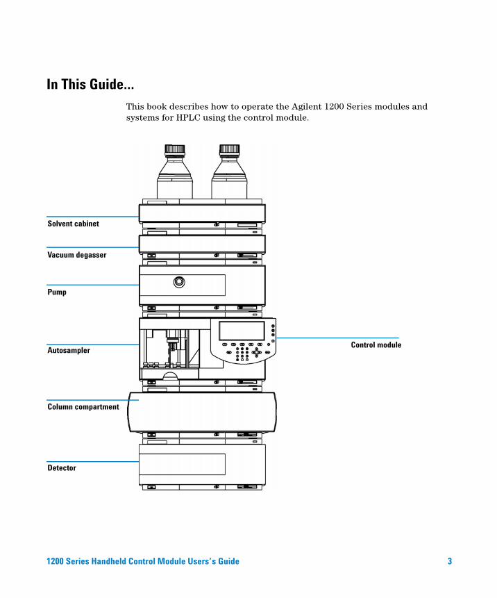
This book describes how to operate the Agilent 1200 Series modules and systems for HPLC using the control module.
Solvent cabinet
Vacuum degasser
Pump
Column compartment
Autosampler
Detector
Control module
ld Control Module Users’s Guide
3
4
The control module provides complete local control and monitoring of a single module or an entire Agilent 1200 Series system. There is no data evaluation in the control module. The control module allows you to do a variety of HPLC tasks including automated sample preparation and injection, isocratic, gradient and multiple method analyses.
Chapter Overview
Part 1
Using the Agilent 1200 Series Control ModuleThis part describes the control mode, its features and its functionality.
1
The Agilent 1200 Series Control ModuleThis chapter gives an overview over the Agilent 1200 Series control module.
2
Working with the Control ModuleThis chapter describes how to use the Agilent 1200 Series control module.
Part 2
Using the Agilent 1200 Series ModulesThis part describes how to use the individual HPLC modules to run isocratic, gradient and multiple-vial analyses using a single method or more than one method.
3
Using the PumpThis chapter contains operational details for the Agilent 1200 Series pumping systems.
4
Using the DegasserThis chapter contains operational details for the Agilent 1200 Series vacuum degasser.
5
Using the AutosamplerThis chapter contains operational details for the Agilent 1200 Series autosampler.
1200 Series Handheld Control Module Users’s Guide
6
1200 Series Handhe
Using the Manual Injection Valve
This chapter contains operational details for the Agilent 1200 Series manual injection valve.
7
Using the DetectorsThis chapter contains operational details for the Agilent 1200 Series variable wavelength, multiple wavelength, refractive index, fluorescence light, and diode array detectors.
8
Using the Column CompartmentThis chapter contains operational details for the Agilent 1200 Series thermostatted column compartment.
Part 3
Using the Agilent 1200 Series LC System With Control ModuleThis part describes how to run isocratic, gradient and multiple-vial analyses using a single method or more than one method.
9
Running an Isocratic AnalysisThis chapter describes how to analyze the Agilent Technologies isocratic standard sample using a single injection analysis.
10
Running a Gradient AnalysisThis chapter describes how to analyze the Agilent Technologies isocratic standard sample using a gradient analysis.
11
Running Multiple-Vial AnalysesThis chapter descibes how to setup multiple vial analyses using the same method and different methods.
12
Running an Injector ProgramThis chapter descibes how to create an injector program.
13
Maintaining the Control ModuleThis chapter shows the repair items.
ld Control Module Users’s Guide 5
A
6
Appendix
This chapter contains safety information.
Related Documents
Each HPLC module is supplied with a Reference Manual or User Manual.
The control module is supplied with the following:
• User’s Guide
• Software Overview Guide
1200 Series Handheld Control Module Users’s Guide
Contents
1 The Agilent 1200 Series Control Module 15
Control Module Features 16
Control Module Keys 17
The i (info) key - Online Information System 19The m (menu) key 20The Esc key 20The Enter key 21Navigation keys 21Action keys 21Selection keys 21Direction keys 21Numeric/Alphanumeric keys 22
Control Module Software 23
The Control Module User Interface 23Analysis Screen 23System Screen 27Status Screen 29Samples Screen 30Plot Screen 31
Control Module Versions 32
2 Working with the Control Module 35
Installing the Control Module 36
General Functions 37
Turning On/Off LC System and Modules 37Setting Date and Time 37
1200 Series Handheld Control Module Users’s Guide 7
Contents
Setting Display Contrast 37Adjusting View 38Configuring the LC System 38
Troubleshooting 39
Troubleshooting the Control Module 39
Inserting and Removing PC cards 40
Working with Methods 41
Loading a Method 41Modifying a Method 42Specifying a Method Name 42Protecting a Method 43Saving a Method 44Deleting a Method 45Exchanging Methods With the PC Card 45Transferring Methods Between LC Systems 46
Time Programming 47
Automating Analyses 48
Displaying Data Graphically 50
Selecting Signals 50Rescaling the Plot Screen 51Toggling Signals 52Displaying Exact Signal Values 52Print Graph 52
Logbooks 53
Maintenance Logbook 53Error Logbook 54System Logbook 54EMF (Early Maintenance Feedback) 54
Printing Screens 55
Print Plot 55
8 1200 Series Handheld Control Module Users’s Guide
Contents
Print Logbooks 56Print Method 56Print Timetable 56Print Sequence 56Print Injector Program 56
Connecting External Devices 57
APG Remote 57GPIB 59Serial / RS-232 59MIO 59BCD 59External Contacts 59
Firmware Updates 60
Coexecution with Agilent ChemStation 61
Features 61Restrictions 62
3 Using the Pump 63
Turning the Pump On and Off 64
Entering Settings 64
Purging the Pump 64
Purging Procedure 65
Adjusting Compressibility 66
Adjusting Stroke Volume 68
Automatic Shut-down 68
Troubleshooting the Pump 68
Tracking Pump History / Pump EMF Limits 69
Resetting the Pump 70
1200 Series Handheld Control Module Users’s Guide 9
Contents
Resetting the Pump Settings 70
4 Using the Degasser 71
Starting the Degasser 72
Removing Gas Bubbles 72
Changing Solvents 73
5 Using the Autosampler 75
Configuring the Autosampler 76
Configuring Interfaces 76
Entering Settings 77
Setting the Injection Mode 77Optimizing Autosampler Performance 78Setting up the Thermostatted Autosampler 79
Aligning Transport Arm/Gripper 80
Tracking Autosampler History / EMF limits 81
Resetting the Autosampler 81
Reset to Default Settings 81
Troubleshooting the Autosampler 82
6 Using the Manual Injection Valve 83
About the Injection Valve 84
Making An Injection 85
Completely Filling the Sample Loop 85
Partially Filling the Sample Loop 86
How Much Sample Is Actually Injected? 86
How Much Sample Do I Need? 87
An Alternative Way to Fill The Loop 87
10 1200 Series Handheld Control Module Users’s Guide
Contents
7 Using the Detectors 89
Turning the Lamp On and Off 90
Entering Settings 91
Diode Array Detector 91Variable Wavelength Detector 91Fluorescence Light Detector 91Multiple Wavelength Detector 92Refractive Index Detector 92
Resetting the Baseline 93
Configuring the Detector 94
Troubleshooting the Detector 95
Tracking Detector History 96
Resetting the Detector 97
Lamp Ignition Routine (VWD only) 98
Configuring the Analog Channel Output 99
8 Using the Column Compartment 101
Turning the Column Compartment On and Off 102
Entering Settings 103
Configuring the Column Compartment 104
Configuring the Column ID Module 105
Selecting Separated or Combined Mode 106
Selecting the Column Switching Valve (optional) 107
Troubleshooting the Column Compartment 108
Tracking Column Compartment History 109
Tracking Column ID History 110
Resetting the Column Compartment 111
1200 Series Handheld Control Module Users’s Guide 11
Contents
9 Running an Isocratic Analysis 113
What You Will Need 114
Preparing the LC System 115
Entering Settings 116
Saving Settings in a Method 118
Observing the Chromatogram 119
Starting the Analysis 121
10 Running a Gradient Analysis 123
What You Will Need 124
Preparing the LC System 125
Entering Settings 126
Saving Settings in a Method 128
Observing the Chromatogram 129
Starting the Analysis 131
11 Running Multiple-Vial Analyses 133
Analyzing Multiple Vials Using the Same Method 134
Analyzing Multiple Vials Using Different Methods 135
Single-Level Calibration Sequences 137
Multiple-Level Calibration Sequences 139
Recalibrating With the Same Group of Standards 139Recalibrating With Multiple Groups of Standards 141
Synchronizing Analyses with External Devices 144
Standard 144Send Single Start Request 145Send Repeated Start Request 146Wait for Single (External) Start Request 146
12 1200 Series Handheld Control Module Users’s Guide
Contents
Wait for Repeated Start Request 147
12 Running an Injector Program 149
Creating an Injector Program 150
Entering Injector Program Settings 151
Injector Program Lines 152
Saving the Method 153
13 Maintaining the Control Module 155
Control Module Parts 156
A Appendix 157
Safety Information 158
General 158Operation 158Safety Symbols 159
Radio Interference 161
Test and Measurement 161
Agilent Technologies on Internet 161
Index 163
1200 Series Handheld Control Module Users’s Guide 13

14
Contents
1200 Series Handheld Control Module Users’s Guide
Agilent 1200 Series Handheld Control ModuleUser’s Guide
1The Agilent 1200 Series Control Module
Control Module Features 16
Control Module Keys 17
Control Module Software 23
Control Module Versions 32
15Agilent Technologies
1 The Agilent 1200 Series Control ModuleControl Module Features
Control Module Features
16
The control module provides complete local control and monitoring of a single module or an entire Agilent 1200 Series system. You have easy access on every supported function, you can easily control all parameters and settings and you can configure various communication channels with other devices, in order to comfortably analyze the generated data.
• Install any desired configuration of Agilent 1200 Series modules. The control module software will reflect which modules are present in the LC system and adjust the screens accordingly.
• Enter parameter settings for every module, perform reset and on/off functions as well as calibration and configuration settings in a self-explanatory and intuitive way.
• Define automated analyses including methods, timetables, injector programs, method sequences and automated calibration settings using the control module.
• Protect your method from any inadvertent keyboard changes by setting method protection.
• Use PC cards to store and transfer methods and sequences between Agilent1200 systems.
• Monitor all operations and error events using the self-updating logbooks.
• Use the context-sensitive online information system to get further information on all topics.
• Use the context-sensitive menu function to have the quickest access on related functions.
• To help comply with Good Laboratory Practice (GLP) regulations you can select a variety of module tests that will check the performance of the LC system.
• The early maintenance feedback (EMF) limits can be used for scheduling maintenance work.
• Display data graphically using the Plot screen where as many as three different signals can be monitored at the same time.
• Print information to a PCL3 compatible printer connected to the serial RS232 port of a Agilent1200 module.
1200 Series Handheld Control Module Users’s Guide
The Agilent 1200 Series Control Module 1Control Module Keys
Control Module Keys
1200 Series Handhe
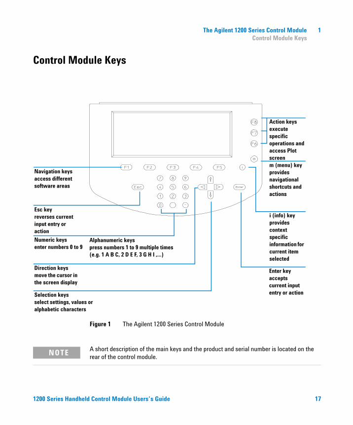
Figure 1 The Agilent 1200 Series Control Module
i (info) keyprovides context specific information for current item selected
Enter keyaccepts current input entry or action
s or
Action keysexecute specific operations and access Plot screenm (menu) keyprovides navigational shortcuts and actions
Alphanumeric keyspress numbers 1 to 9 multiple times(e.g. 1 A B C, 2 D E F, 3 G H I ,…)
NOTE A short description of the main keys and the product and serial number is located on the rear of the control module.
ld Control Module Users’s Guide
Selection keysselect settings, valuealphabetic characters
Direction keysmove the cursor in the screen display
Navigation keysaccess different software areas
Esc keyreverses current input entry or action
Numeric keysenter numbers 0 to 9
17
18
1 The Agilent 1200 Series Control ModuleControl Module Keys
The display will show you a variety of menu buttons [F1-F5] (in the lower section) or function buttons [F6-F8] (in the right hand section) that can be accessed with the corresponding Navigation (for menus) and Action (for functions) keys.
NOTE In this context the expression “button” will always refer to a menu or function shown on the display, whereas “key” refers to the actual keys on the keyboard. The key corresponding to a certain button is shown in brackets [F1-F8]
1200 Series Handheld Control Module Users’s Guide
The Agilent 1200 Series Control Module 1Control Module Keys
The i (info) key - Online Information System
1200 Series Handhe
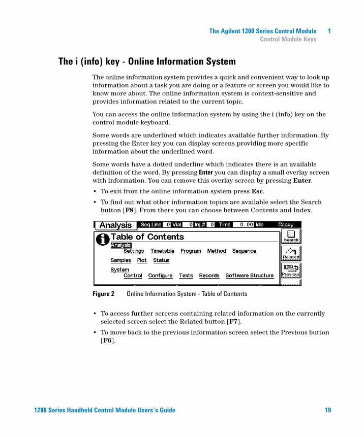
The online information system provides a quick and convenient way to look up information about a task you are doing or a feature or screen you would like to know more about. The online information system is context-sensitive and provides information related to the current topic.
You can access the online information system by using the i (info) key on the control module keyboard.
Some words are underlined which indicates available further information. By pressing the Enter key you can display screens providing more specific information about the underlined word.
Some words have a dotted underline which indicates there is an available definition of the word. By pressing Enter you can display a small overlay screen with information. You can remove this overlay screen by pressing Enter.
• To exit from the online information system press Esc.
• To find out what other information topics are available select the Search button [F8]. From there you can choose between Contents and Index.
• To access further screens containing related information on the currently selected screen select the Related button [F7].
• To move back to the previous information screen select the Previous button [F6].
Figure 2 Online Information System - Table of Contents
ld Control Module Users’s Guide 19
1 The Agilent 1200 Series Control ModuleControl Module Keys
The m (menu) key
20
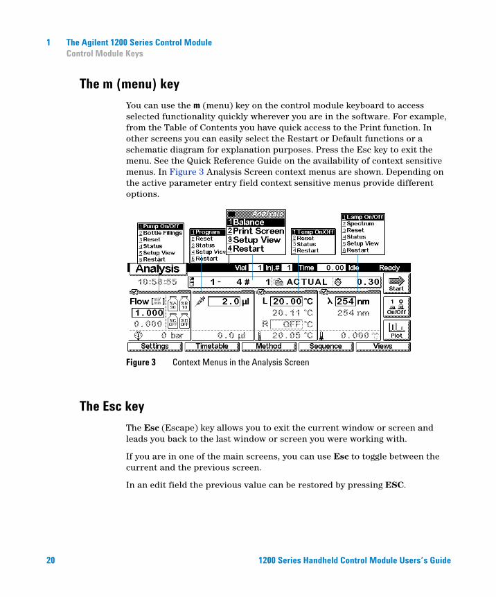
You can use the m (menu) key on the control module keyboard to access selected functionality quickly wherever you are in the software. For example, from the Table of Contents you have quick access to the Print function. In other screens you can easily select the Restart or Default functions or a schematic diagram for explanation purposes. Press the Esc key to exit the menu. See the Quick Reference Guide on the availability of context sensitive menus. In Figure 3 Analysis Screen context menus are shown. Depending on the active parameter entry field context sensitive menus provide different options.
Figure 3 Context Menus in the Analysis Screen
The Esc key
The Esc (Escape) key allows you to exit the current window or screen and leads you back to the last window or screen you were working with.
If you are in one of the main screens, you can use Esc to toggle between the current and the previous screen.
In an edit field the previous value can be restored by pressing ESC.
1200 Series Handheld Control Module Users’s Guide
The Agilent 1200 Series Control Module 1Control Module Keys
The Enter key
1200 Series Handhe
With Enter you accept a current entry or action. When entering a parameter into a certain field, Enter leads you on to the next accessible entry field. In this case it has the same function as the right Direction key.
Navigation keys
These 5 keys [F1 - F5] allow you to switch between the menus. Within these menus the relevant parameters can be set and certain functions can be accessed. The Navigation keys always correspond to a button displayed above them on the screen. The menus accessed via the buttons vary according to the screen you are working with. In some cases pressing a button will cause a list box to appear. From there you must make a choice in order to proceed.
Action keys
The 3 Action keys [F6-F8] trigger a variety of functions. The available functions depend on the screen you are working with.
Selection keys
With the Selection keys (arrow up/down) you can select settings in various list boxes. You can also change values in certain parameter entry fields or enter alphanumeric characters.
Direction keys
With the Direction keys (arrow left/right) you can move back and forth between the entry fields.
ld Control Module Users’s Guide 21
1 The Agilent 1200 Series Control ModuleControl Module Keys
Numeric/Alphanumeric keys
22
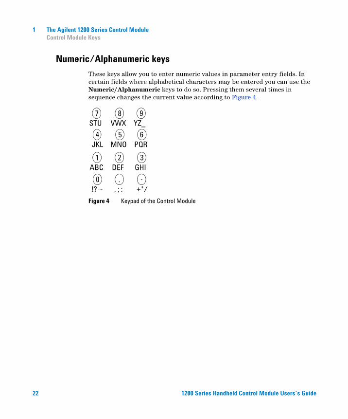
These keys allow you to enter numeric values in parameter entry fields. In certain fields where alphabetical characters may be entered you can use the Numeric/Alphanumeric keys to do so. Pressing them several times in sequence changes the current value according to Figure 4.
Figure 4 Keypad of the Control Module
-+*/
., ; :
7STU
6PQR
5MNO
1ABC
4JKL
3GHI
2DEF
0!?
9YZ_
8VWX
1200 Series Handheld Control Module Users’s Guide
The Agilent 1200 Series Control Module 1Control Module Software
Control Module Software
The Control Module User Interface
1200 Series Handhe
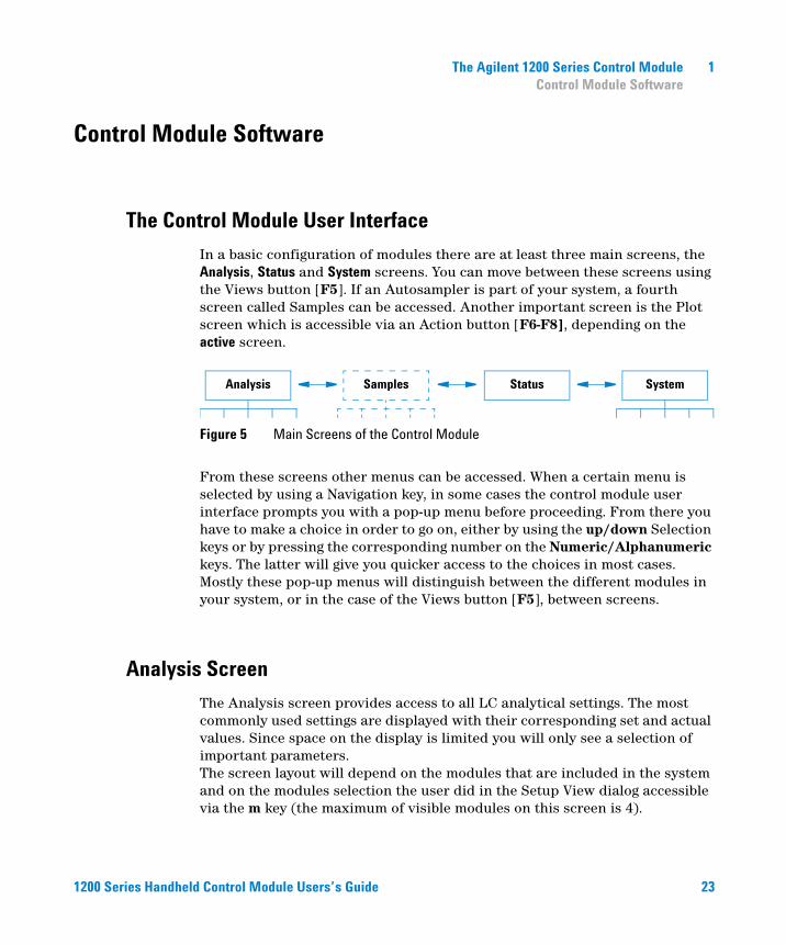
In a basic configuration of modules there are at least three main screens, the Analysis, Status and System screens. You can move between these screens using the Views button [F5]. If an Autosampler is part of your system, a fourth screen called Samples can be accessed. Another important screen is the Plot screen which is accessible via an Action button [F6-F8], depending on the active screen.
From these screens other menus can be accessed. When a certain menu is selected by using a Navigation key, in some cases the control module user interface prompts you with a pop-up menu before proceeding. From there you have to make a choice in order to go on, either by using the up/down Selection keys or by pressing the corresponding number on the Numeric/Alphanumeric keys. The latter will give you quicker access to the choices in most cases. Mostly these pop-up menus will distinguish between the different modules in your system, or in the case of the Views button [F5], between screens.
Figure 5 Main Screens of the Control Module
SystemAnalysis StatusSamples
Analysis Screen
The Analysis screen provides access to all LC analytical settings. The most commonly used settings are displayed with their corresponding set and actual values. Since space on the display is limited you will only see a selection of important parameters. The screen layout will depend on the modules that are included in the system and on the modules selection the user did in the Setup View dialog accessible via the m key (the maximum of visible modules on this screen is 4).
ld Control Module Users’s Guide 23
24
1 The Agilent 1200 Series Control ModuleControl Module Software
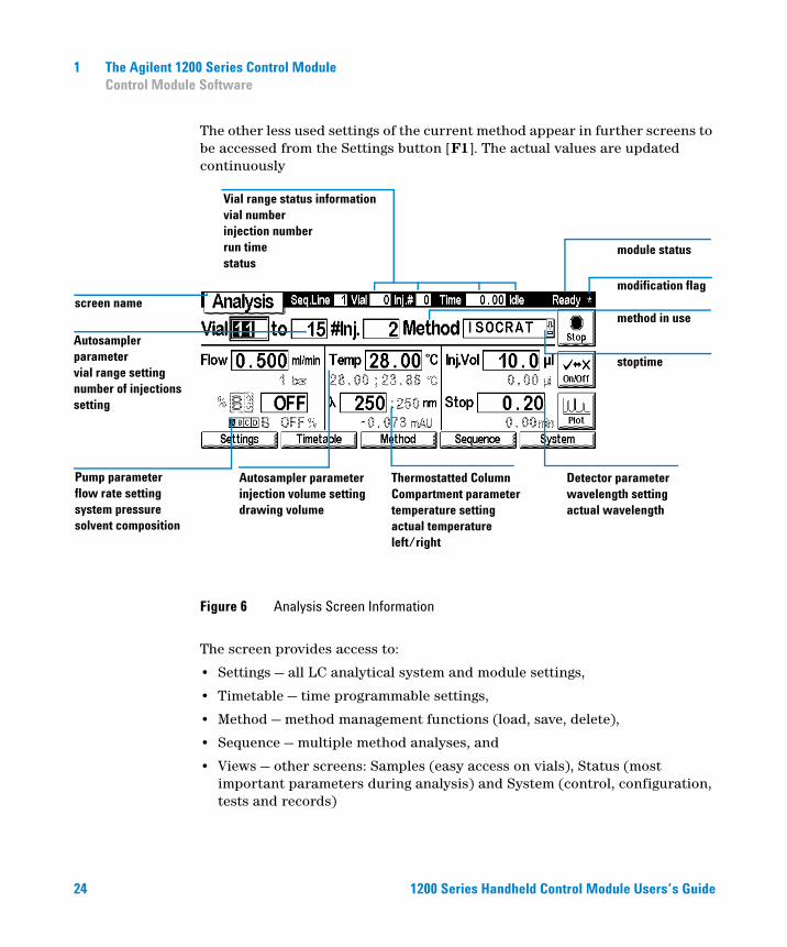
The other less used settings of the current method appear in further screens to be accessed from the Settings button [F1]. The actual values are updated continuously
The screen provides access to:
• Settings — all LC analytical system and module settings,
• Timetable — time programmable settings,
• Method — method management functions (load, save, delete),
• Sequence — multiple method analyses, and
• Views — other screens: Samples (easy access on vials), Status (most important parameters during analysis) and System (control, configuration, tests and records)
Figure 6 Analysis Screen Information
modification flag
module status
Autosampler parameterinjection volume settingdrawing volume
Vial range status informationvial numberinjection numberrun timestatus
method in use
stoptime
Thermostatted Column Compartment parametertemperature settingactual temperature left/right
Detector parameterwavelength settingactual wavelength
Autosampler parametervial range settingnumber of injections setting
screen name
1200 Series Handheld Control Mo
Pump parameterflow rate settingsystem pressuresolvent composition
dule Users’s Guide
1200 Series Handhe
The Agilent 1200 Series Control Module 1Control Module Software
The Start/Stop button [F8] starts or stops a single injection or a multiple injection analysis.
The On/Off button [F7] turns the pump, detector lamp, heater and thermostatted column on or off.
The Plot button [F6] provides direct access to the Plot screen where all important parameters can be displayed graphically. It is possible to display several parameters at the same time.
Using the m (menu) key in the Analysis screen prompts context sensitive menus depending on the active parameter entry field (see Figure 3 on page 20).
The Module Status on the top right hand side of the screen and on top of the individual module tabs indicates whether the system/ module is ready or not.
indicates the system is ready, indicates the system/ module is not ready, (only applicable for individual modules) indicates that a vital error has occurred in the module.
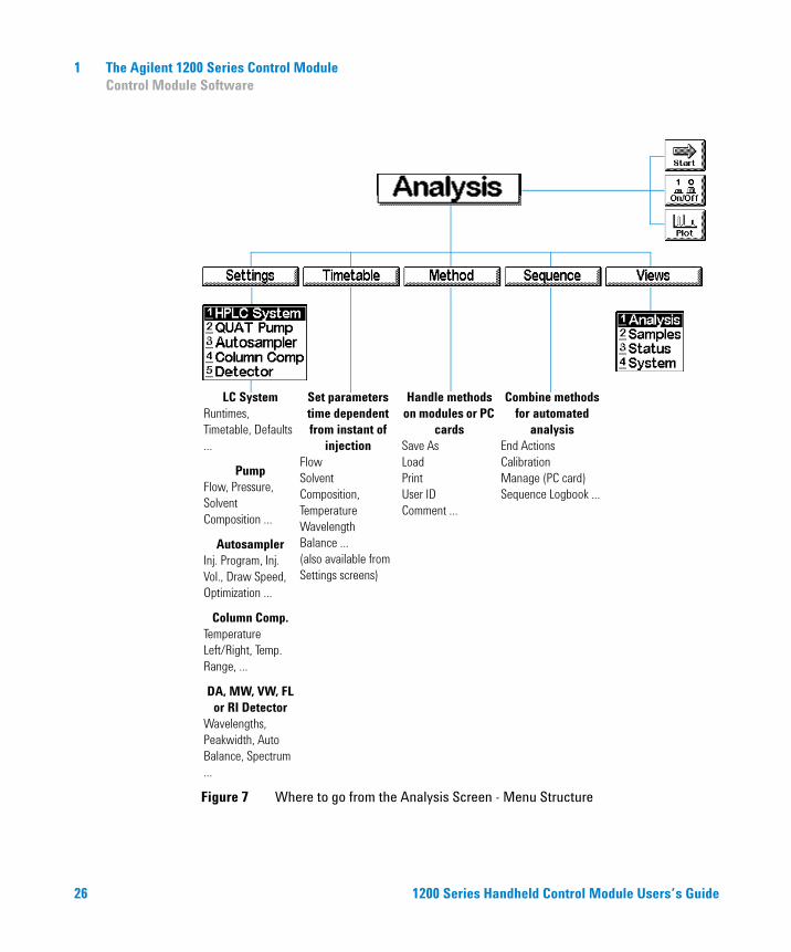
The following diagram shows the functionality available in the Analysis screen for an LC system comprising a pump, an autosampler, a thermostatted column compartment and a detector (e.g. Variable Wavelength Detector, Diode Array Detector, Multiple Wavelength Detector).
ld Control Module Users’s Guide 25
26
1 The Agilent 1200 Series Control ModuleControl Module Software
Figure 7 Where to go from the Analysis Screen - Menu Structure
Set parameters time dependent from instant of
injectionFlowSolvent Composition,TemperatureWavelengthBalance ...(also available from Settings screens)
LC SystemRuntimes, Timetable, Defaults ...
PumpFlow, Pressure, Solvent Composition ...
AutosamplerInj. Program, Inj. Vol., Draw Speed, Optimization ...
Column Comp.Temperature Left/Right, Temp. Range, ...
DA, MW, VW, FL or RI Detector
Wavelengths, Peakwidth, Auto Balance, Spectrum ...
Handle methods on modules or PC
cardsSave AsLoadPrintUser IDComment ...
Combine methods for automated
analysisEnd ActionsCalibrationManage (PC card)Sequence Logbook ...
Analysis
Settings Timetable Method Sequence Views
LC SystemPump
AutosamplerDetectors
Col. Compartment
Analysis(Samples)
SetupSystem
Start
Plot
On/Off
1200 Series H
andheld Control Module Users’s Guide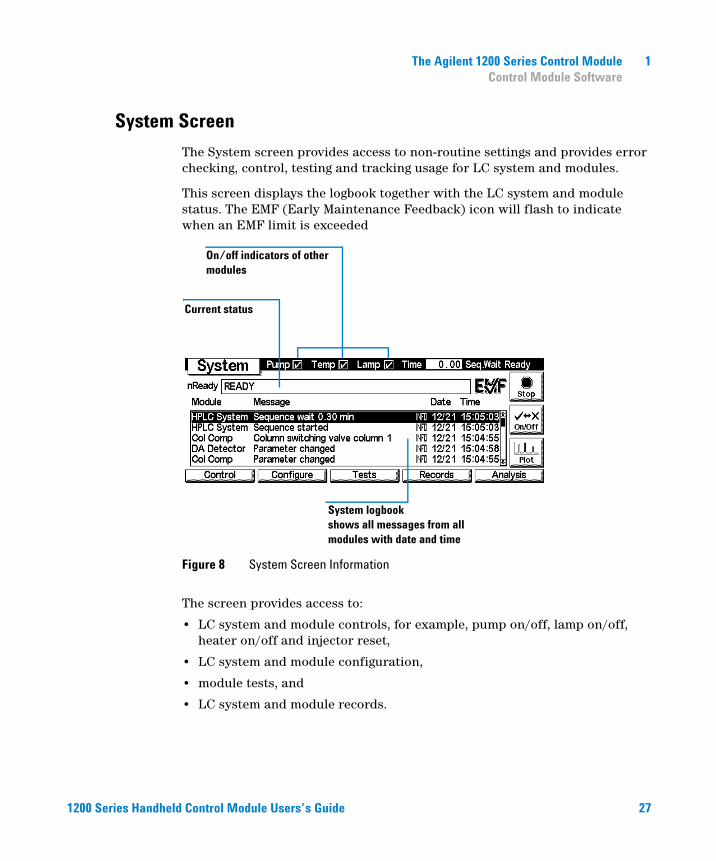
The Agilent 1200 Series Control Module 1Control Module Software
System Screen
1200 Series Handhe
The System screen provides access to non-routine settings and provides error checking, control, testing and tracking usage for LC system and modules.
This screen displays the logbook together with the LC system and module status. The EMF (Early Maintenance Feedback) icon will flash to indicate when an EMF limit is exceeded
The screen provides access to:
• LC system and module controls, for example, pump on/off, lamp on/off, heater on/off and injector reset,
• LC system and module configuration,
• module tests, and
• LC system and module records.
Figure 8 System Screen Information
System logbookshows all messages from all modules with date and time
On/off indicators of other modules
Current status
ld Control Module Users’s G
uide 27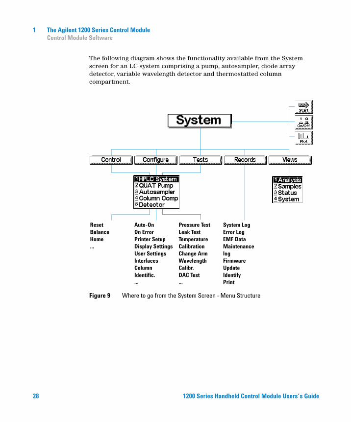
28
1 The Agilent 1200 Series Control ModuleControl Module Software
The following diagram shows the functionality available from the System screen for an LC system comprising a pump, autosampler, diode array detector, variable wavelength detector and thermostatted column compartment.
Figure 9 Where to go from the System Screen - Menu Structure
Auto-OnOn ErrorPrinter SetupDisplay SettingsUser SettingsInterfacesColumn Identific....
ResetBalanceHome...
Pressure TestLeak TestTemperature CalibrationChange ArmWavelength Calibr.DAC Test...
System LogError LogEMF DataMaintenance logFirmware UpdateIdentifyPrint
System
Control Configure Tests Records Views
LC SystemPump
AutosamplerDetectorsCol. Comp.
Analysis(Samples)
SetupSystem
Start
Plot
On/Off
1200 Series H
andheld Control Module Users’s Guide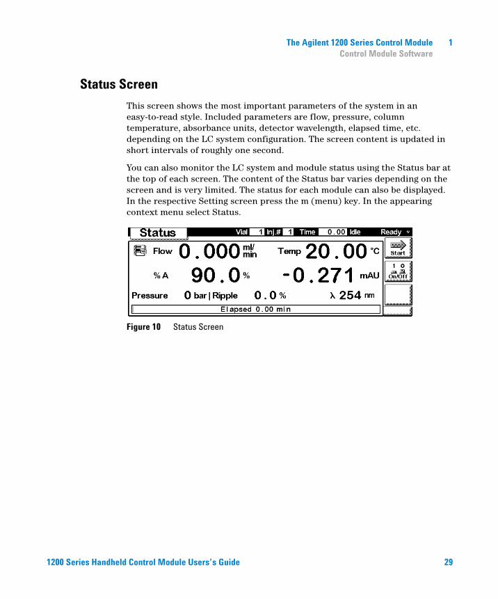
The Agilent 1200 Series Control Module 1Control Module Software
Status Screen
1200 Series Handhe
This screen shows the most important parameters of the system in an easy-to-read style. Included parameters are flow, pressure, column temperature, absorbance units, detector wavelength, elapsed time, etc. depending on the LC system configuration. The screen content is updated in short intervals of roughly one second.
You can also monitor the LC system and module status using the Status bar at the top of each screen. The content of the Status bar varies depending on the screen and is very limited. The status for each module can also be displayed. In the respective Setting screen press the m (menu) key. In the appearing context menu select Status.
Figure 10 Status Screen
ld Control Module Users’s Guide 29
1 The Agilent 1200 Series Control ModuleControl Module Software
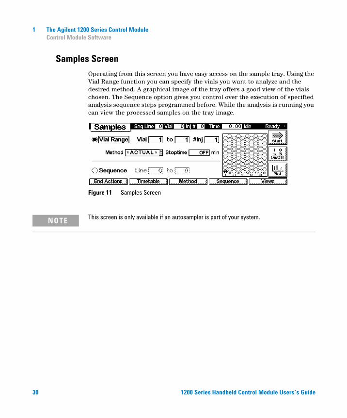
Samples Screen
30
Operating from this screen you have easy access on the sample tray. Using the Vial Range function you can specify the vials you want to analyze and the desired method. A graphical image of the tray offers a good view of the vials chosen. The Sequence option gives you control over the execution of specified analysis sequence steps programmed before. While the analysis is running you can view the processed samples on the tray image.
Figure 11 Samples Screen
NOTE This screen is only available if an autosampler is part of your system.
1200 Series Handheld Control Module Users’s Guide
The Agilent 1200 Series Control Module 1Control Module Software
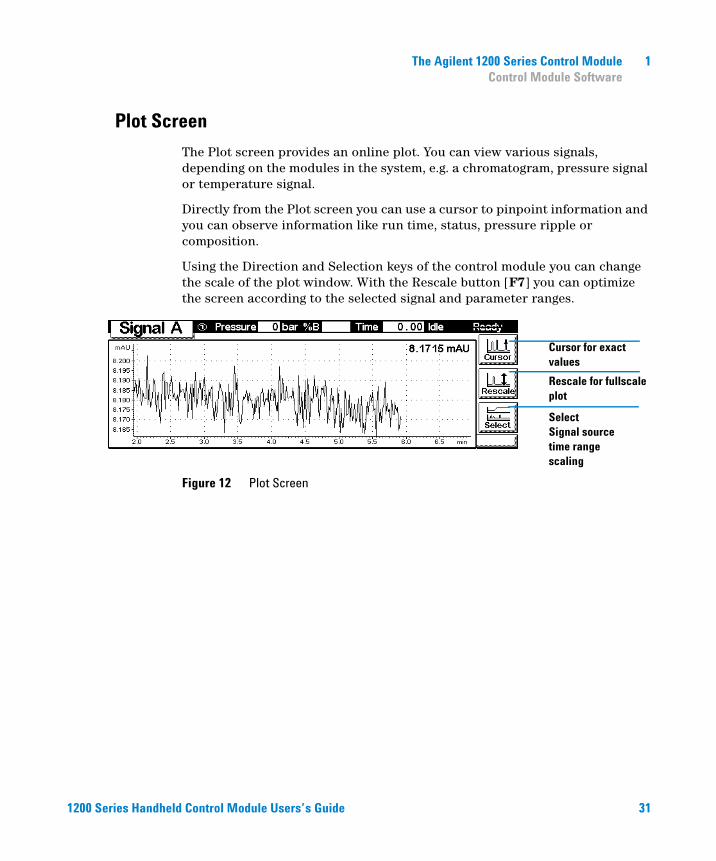
Plot Screen
1200 Series Handhe
The Plot screen provides an online plot. You can view various signals, depending on the modules in the system, e.g. a chromatogram, pressure signal or temperature signal.
Directly from the Plot screen you can use a cursor to pinpoint information and you can observe information like run time, status, pressure ripple or composition.
Using the Direction and Selection keys of the control module you can change the scale of the plot window. With the Rescale button [F7] you can optimize the screen according to the selected signal and parameter ranges.
Figure 12 Plot Screen
Cursor for exact values
Rescale for fullscale plot
SelectSignal sourcetime rangescaling
ld Control Module Users’s Guide
31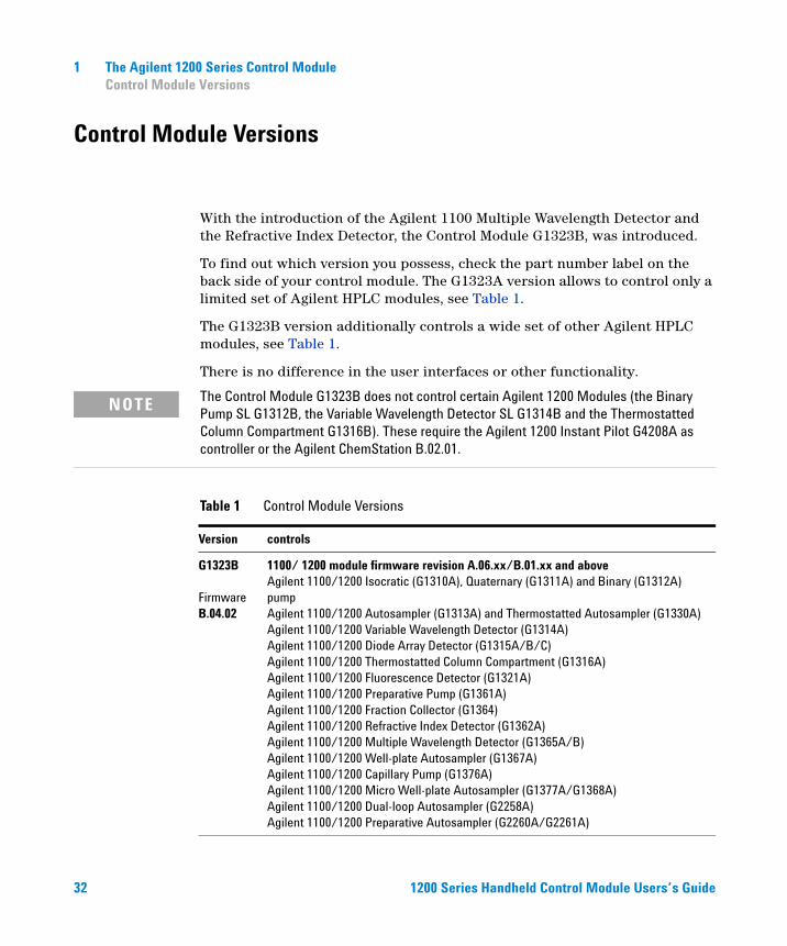
1 The Agilent 1200 Series Control ModuleControl Module Versions
Control Module Versions
32
With the introduction of the Agilent 1100 Multiple Wavelength Detector and the Refractive Index Detector, the Control Module G1323B, was introduced.
To find out which version you possess, check the part number label on the back side of your control module. The G1323A version allows to control only a limited set of Agilent HPLC modules, see Table 1.
The G1323B version additionally controls a wide set of other Agilent HPLC modules, see Table 1.
There is no difference in the user interfaces or other functionality.
The Control Module G1323B does not control certain Agilent 1200 Modules (the Binary
NOTEPump SL G1312B, the Variable Wavelength Detector SL G1314B and the Thermostatted Column Compartment G1316B). These require the Agilent 1200 Instant Pilot G4208A as controller or the Agilent ChemStation B.02.01.Table 1 Control Module Versions
Version controls
G1323B
Firmware B.04.02
1100/ 1200 module firmware revision A.06.xx/B.01.xx and aboveAgilent 1100/1200 Isocratic (G1310A), Quaternary (G1311A) and Binary (G1312A) pumpAgilent 1100/1200 Autosampler (G1313A) and Thermostatted Autosampler (G1330A)Agilent 1100/1200 Variable Wavelength Detector (G1314A) Agilent 1100/1200 Diode Array Detector (G1315A/B/C)Agilent 1100/1200 Thermostatted Column Compartment (G1316A) Agilent 1100/1200 Fluorescence Detector (G1321A)Agilent 1100/1200 Preparative Pump (G1361A)Agilent 1100/1200 Fraction Collector (G1364)Agilent 1100/1200 Refractive Index Detector (G1362A)Agilent 1100/1200 Multiple Wavelength Detector (G1365A/B)Agilent 1100/1200 Well-plate Autosampler (G1367A)Agilent 1100/1200 Capillary Pump (G1376A)Agilent 1100/1200 Micro Well-plate Autosampler (G1377A/G1368A)Agilent 1100/1200 Dual-loop Autosampler (G2258A)Agilent 1100/1200 Preparative Autosampler (G2260A/G2261A)
1200 Series Handheld Control Module Users’s Guide
1200 Series Handhe
The Agilent 1200 Series Control Module 1Control Module Versions
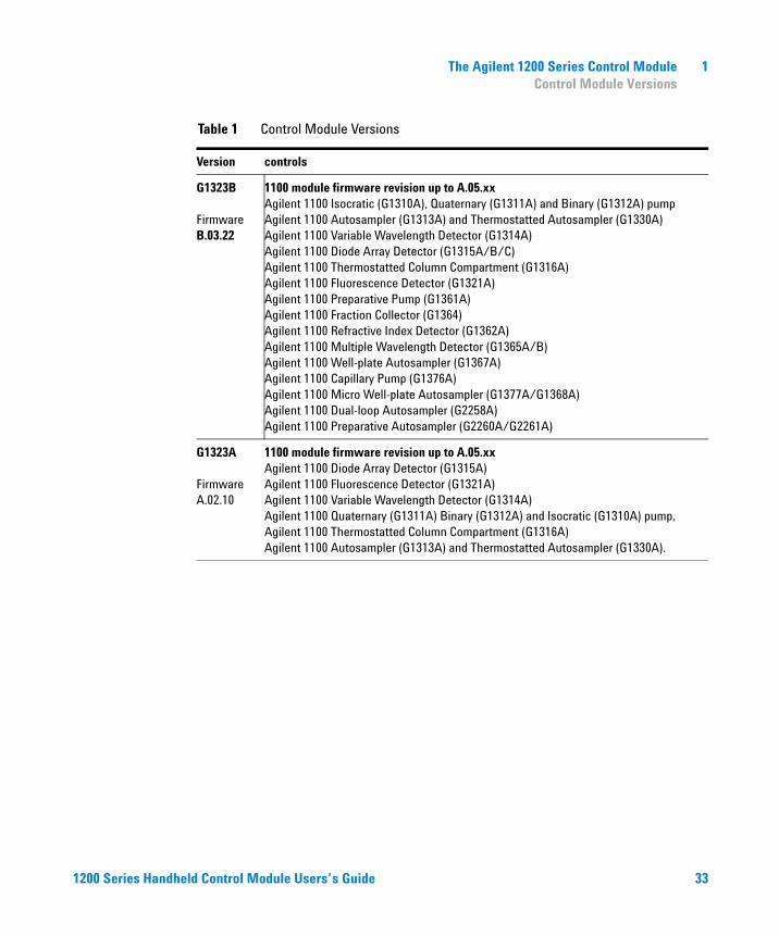
G1323B
Firmware B.03.22
1100 module firmware revision up to A.05.xxAgilent 1100 Isocratic (G1310A), Quaternary (G1311A) and Binary (G1312A) pumpAgilent 1100 Autosampler (G1313A) and Thermostatted Autosampler (G1330A)Agilent 1100 Variable Wavelength Detector (G1314A) Agilent 1100 Diode Array Detector (G1315A/B/C)Agilent 1100 Thermostatted Column Compartment (G1316A) Agilent 1100 Fluorescence Detector (G1321A)Agilent 1100 Preparative Pump (G1361A)Agilent 1100 Fraction Collector (G1364)Agilent 1100 Refractive Index Detector (G1362A)Agilent 1100 Multiple Wavelength Detector (G1365A/B)Agilent 1100 Well-plate Autosampler (G1367A)Agilent 1100 Capillary Pump (G1376A)Agilent 1100 Micro Well-plate Autosampler (G1377A/G1368A)Agilent 1100 Dual-loop Autosampler (G2258A)Agilent 1100 Preparative Autosampler (G2260A/G2261A)
G1323A
Firmware A.02.10
1100 module firmware revision up to A.05.xxAgilent 1100 Diode Array Detector (G1315A)Agilent 1100 Fluorescence Detector (G1321A)Agilent 1100 Variable Wavelength Detector (G1314A) Agilent 1100 Quaternary (G1311A) Binary (G1312A) and Isocratic (G1310A) pump, Agilent 1100 Thermostatted Column Compartment (G1316A) Agilent 1100 Autosampler (G1313A) and Thermostatted Autosampler (G1330A).
Table 1 Control Module Versions
Version controls
ld Control Module Users’s Guide 33

34
1 The Agilent 1200 Series Control ModuleControl Module Versions
1200 Series Handheld Control Module Users’s Guide
Agilent 1200 Series Handheld Control ModuleUser’s Guide
2Working with the Control Module
Installing the Control Module 36
General Functions 37
Troubleshooting 39
Inserting and Removing PC cards 40
Working with Methods 41
Time Programming 47
Automating Analyses 48
Displaying Data Graphically 50
Logbooks 53
Printing Screens 55
Connecting External Devices 57
Firmware Updates 60
Coexecution with Agilent ChemStation 61
35Agilent Technologies
2 Working with the Control ModuleInstalling the Control Module
Installing the Control Module
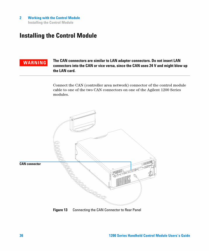
WARNING The CAN connectors are similar to LAN adapter connectors. Do not insert LAN connectors into the CAN or vice versa, since the CAN uses 24 V and might blow up the LAN card.
36
Connect the CAN (controller area network) connector of the control module cable to one of the two CAN connectors on one of the Agilent 1200 Series modules.
Figure 13 Connecting the CAN Connector to Rear Panel
CAN connector
1200 Series Handheld Control Module Users’s Guide
Working with the Control Module 2General Functions
General Functions
Turning On/Off LC System and Modules
1200 Series Handhe
Use the On/Off button [F7] in the Analysis screen to turn on or off either the complete system or each module individually.
Setting Date and Time
You can set the date and time using the context menu (m key) while the System screen is active. Choose the Date & Time option and press Enter . Press Setup button [F6] to change the settings. Press Done [F6] to confirm the new entries. Alternatively, choose Configure and select LC System. Press Date& Time [F4]. When date and time are changed in the control module, the settings are automatically stored in all the connected modules. The date and time are backed up by a battery in each module. The control module does not have a clock of its own.
Setting Display Contrast
NOTE Upon startup the modules synchronize their internal clocks. The clocks can also be synchronized by an external chromatographic data system, like the Agilent ChemStation.
From the System screen choose Configure and select LC System. Press Display and then use the Selection keys to enter values between 0 and 31 to adjust the display contrast according to your personal and location requirements. Then press Done.
ld Control Module Users’s Guide 37
2 Working with the Control ModuleGeneral Functions
Adjusting View
38
Pressing the m key in the Analysis screen and selecting Setup view allows to select the modules that will be displayed in the Analysis screen. Choosing this option enables you to select the modules present in the Analysis screen. By pressing the Remove/Add buttons [F7, F8] you can move the modules from the Selected Modules to the Available Modules list boxes and vice versa, depending on which module is highlighted.
Configuring the LC System
The LC system is self-configuring to a large extent. It recognizes automatically which modules are installed. The layout of the Analysis screen changes according to the modules present. You can use the Configure button [F2] in the System screen to configure various features such as the Auto-on for the system or Loading (a method), and After Error Condition.
If an error event occurs, you can configure the LC system to load a specified method or turn off the LC system using the After Error Condition setting.
1200 Series Handheld Control Module Users’s Guide
Working with the Control Module 2Troubleshooting
Troubleshooting
1200 Series Handhe
Internal diagnostics continuously monitor the module’s condition and record any unusual events in an electronic logbook. For example, missing vials or leaking solvent will signal errors and record the errors in the logbook together with the time and date the errors occurred. The logbook is self-updating where the newest entry replaces the oldest entry. If a printer is connected you can easily print out the logbook.
Troubleshooting the Control Module
If your control module does not work correctly, disconnect the module CAN connector from the rear of the Agilent 1200 Series module it is attached to and reconnect it.
If the problem still remains, then
• power down all connected devices and computers and wait 1 minute and then restart, or
• try to use just one Agilent 1200 Series module.
If the problem still remains, call Agilent Technologies.
ld Control Module Users’s Guide 39
2 Working with the Control ModuleInserting and Removing PC cards
Inserting and Removing PC cards
40
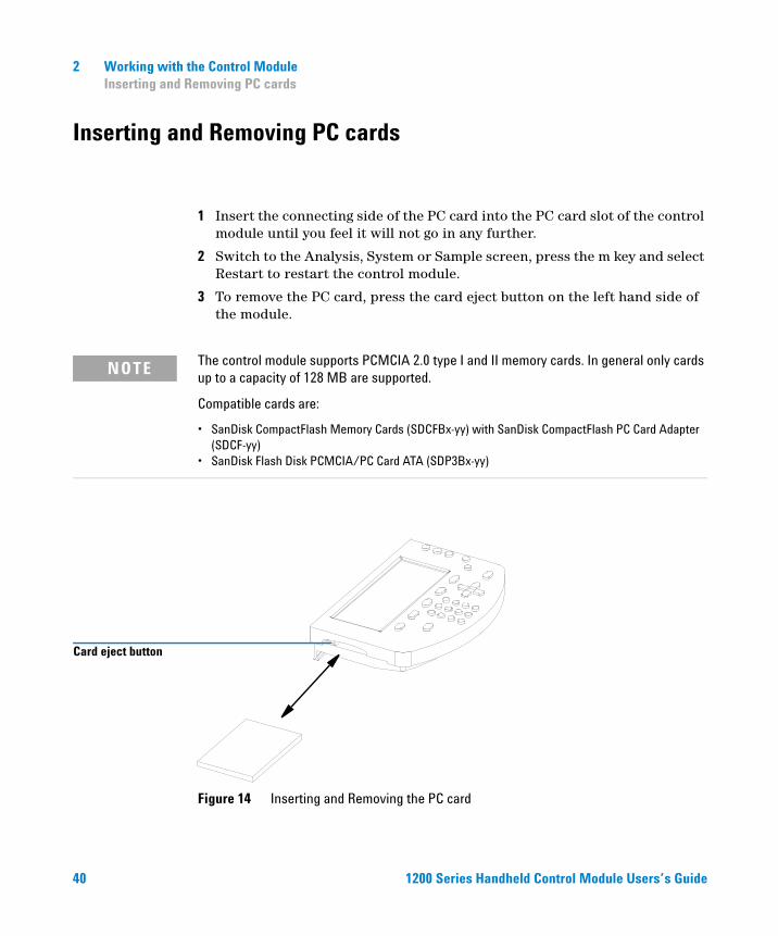
1 Insert the connecting side of the PC card into the PC card slot of the control module until you feel it will not go in any further.
2 Switch to the Analysis, System or Sample screen, press the m key and select Restart to restart the control module.
3 To remove the PC card, press the card eject button on the left hand side of the module.
NOTE The control module supports PCMCIA 2.0 type I and II memory cards. In general only cards up to a capacity of 128 MB are supported.
Compatible cards are:
• SanDisk CompactFlash Memory Cards (SDCFBx-yy) with SanDisk CompactFlash PC Card Adapter (SDCF-yy)
• SanDisk Flash Disk PCMCIA/PC Card ATA (SDP3Bx-yy)
Figure 14 Inserting and Removing the PC card
Card eject button
1200 Series Handheld Control Module Users’s Guide
Working with the Control Module 2Working with Methods
Working with Methods
1200 Series Handhe
A method contains a complete set of injection, separation and detection parameters, including the timetable and injector program. Vial range information is not part of the method.
There are two types of methods:
• The module method. The method parameters are stored in the individual LC modules and not in the control module. A method that is stored in the individual LC modules can be loaded, modified, saved and run from the control module.
• The PC card method. The method parameters are stored on a PC card. A method that is stored on the PC card can be loaded to the LC modules or transferred to another LC system. Methods cannot be run directly from the PC card. The method must first be loaded from the PC card before it can be run. When the PC card method is loaded it becomes a module method.
Unless stated otherwise, the following sections refer to module methods.
Loading a Method
A method can be loaded using the Method button [F3] in the Analysis or Samples screen:
1 Enter the Analysis or Samples screen.
2 Select Method; the current parameters are displayed.
3 Press the Module button [F1].
4 Select a method from the list.
5 Press Enter.
You can also load a method directly from the Analysis screen by using the selection keys and changing the method in the method list.
The Method/Module screen lists all methods that are stored in the modules. For each method there is a date when the method was last changed and a short user description. When a method is loaded it becomes the current method.
ld Control Module Users’s Guide 41
42
2 Working with the Control ModuleWorking with Methods
A method might be identified as partial method. This means, that there is a mismatch between the actual and the original system configuration, for example when a module was added to or removed from the system. A partial method can not be loaded as the current method.
Modifying a Method
A method can be modified by changing the settings in the Analysis or Settings screens.
Many of the commonly-used method settings (flow, injection volume, column temperature, wavelength and stoptime) can be modified in the Analysis screen. Other less commonly-used method settings such as eject speed can be modified using the Settings button [F1]. This button displays the Settings menu from which all LC system and module settings can be accessed.
If you change a method setting, the value is immediately downloaded to the LC module. An asterisk (*) will appear in the right corner of the status line to indicate the current method has been modified.
The time-programmable settings can be modified in the Timetable screen.
The injector program settings can be modified in the Injector Program screen accessed from the Autosampler Settings screen.
Specifying a Method Name
1 Select the Method button [F3] in the Analysis or Samples screen.
2 Select the Save As button [F8].
3 Press the Selection key up to enter the letter input mode.
4 Select the required letter or number in the method name entry box using the Selection keys. Numbers and the minus sign (-) can be entered directly.
1200 Series Handheld Control Module Users’s Guide
Working with the Control Module 2Working with Methods
NOTE Alphanumeric characters can be entered also by pressing the keys 1 to 9 several times (e.g. 1 A B C, 2 D E F, 3 G H I, ....). See also Figure 4 on page 22.
1200 Series Handhe
5 Move the cursor to the next entry position using the right direction key and repeat step 4.
6 Repeat step 4 and step 5 until you have specified your method name.
7 Select the Done button [F6] to accept the method name.
Protecting a Method
NOTE The left arrow key can be used as backspace, the right arrow key is used to move to the next character position.
To protect the current method.
1 Select the Method button [F3] in the Analysis screen.
2 Select Module from the menu.
3 Select the Save As button [F8].
4 Select the Protected check box.
5 Select the Done button [F6].
The method is now protected against inadvertent changes. Any changes to the method will not be accepted until the method is unprotected, by saving it again without protection. For further protection remove the Control Module from the Instrument and store it in a secure place.
Any unauthorized method or instrument changes can be traced by the system logbook.
ld Control Module Users’s Guide 43
2 Working with the Control ModuleWorking with Methods
Saving a Method
44
Although it may seem that methods are stored within the control module, in fact all data concerning methods is stored in the modules themselves. The control module generates a list of all available methods that can be loaded.
The number of methods that can be stored depends on the number of timetable and injector program lines included. In general about 15 methods may be stored which contain about 50 timetable lines per module. With differing method contents the actual amount of methods to be stored may change significantly.
Use PC cards in order to store infinite numbers of methods for future use or exchange between LC instruments (see “Transferring Methods Between LC Systems” on page 46).
To save the current method:
1 Select the Method button [F3] in the Analysis screen.
2 Select Save As using the Action keys.
3 Enter a name as described in “Specifying a Method Name” on page 42, or simply continue with the next step if you want to keep the current method name.
4 Press Enter.
NOTE Optionally you may fill in further data. Activate the Protected check box in order to protect the method. By entering a User ID you can identify your personal modules more quickly. You can also enter a personal comment.
5 Select the Done button [F6] to store the method in the modules. Select Yes to confirm save in case you are overwriting an existing method.
The stored method now contains all the current LC system and module settings. The method settings are stored in the individual modules, e.g., all the pump method settings are stored in the pump and not in the control module.
If you disconnect the control module from one LC system and connect it to another LC system, the current method and settings are now shown for the new LC system. To transfer methods from one LC system to another use a PC card.
1200 Series Handheld Control Module Users’s Guide
Working with the Control Module 2Working with Methods
Deleting a Method
1200 Series Handhe
1 Select the Method button [F3] in the Analysis screen.
2 Select Module from the menu.
3 Select the method from the method list.
4 Select the Delete button [F6].
5 Choose Selected Method from the pop up menu. If you want to delete all methods choose All Methods.
6 Press Enter.
7 Select Yes to confirm the deletion by pressing the Enter key.
Exchanging Methods With the PC Card
To store and retrieve methods from PC card you can use a comfortable screen that allows easy copying to and from PC card.
1 Insert the PC card into the control module as described in “Inserting and Removing PC cards” on page 40.
NOTE Methods from a freshly installed PC card are not available. Restart the control module using the Restart function via the m (menu) key from the main screens.
2 Select the Method button [F3] in the Analysis or Samples screen.
3 Select the PC card button [F2].
NOTE Use the Initialize button [F1] available in this screen in order to initialize a pre-formatted PC card for use with the control module. This has to take place prior to first use in the control module. Be aware that all data on the PC card will be lost.
4 Use the Selection and Direction keys to navigate within and between the method list boxes.
5 Use the “Copy >>” and “Copy <<“ buttons [F7, F8] to copy methods from and to the PC card.
ld Control Module Users’s Guide 45
46
2 Working with the Control ModuleWorking with Methods
If you want to store the current method on PC card, you have to use the Save As function (see “Saving a Method” on page 44) in order to store it in the modules first. From there you can copy it to PC card as described in this section.
Transferring Methods Between LC Systems
Methods can be transferred from one LC system to another using a PC card.
1 Save the method you want to transfer onto a PC card. See section “Exchanging Methods With the PC Card” on page 45.
2 Remove the PC card from the control module.
3 Insert the PC card into the control module of the other LC system.
NOTE If this system does not have a control module connected, use any available control module.
4 Restart the control module using the Restart function via the m (menu) key (available from the main screens).
5 Load the method from the PC card. See section “Exchanging Methods With the PC Card” on page 45.
1200 Series Handheld Control Module Users’s Guide
Working with the Control Module 2Time Programming
Time Programming
1200 Series Handhe
To time-program selected settings during the analysis you can create a timetable. Using the Timetable screen, you can create a time based program that will automatically control the pump, detector, column compartment and external contacts.
In some cases the settings will change instantaneously from the initial value to the value specified after a certain time in the timetable (e.g. wavelength). In other cases (solvent composition) these changes take place dynamically, approaching the set value in a step wise and linear manner.
NOTE The timetable becomes part of the current method when the method is saved.
The timetable is accessed by selecting the Timetable button [F2] in the Analysis screen.
A timetable line can be inserted by pressing the Insert button [F7] and consists of the following:
• TimeSet the time span between the instant of injection and the desired parameter change.
• ModuleChoose the module that controls the parameter you want to change.
• SettingSelect the parameter to be changed.
• ValueEnter the desired parameter value.
You can edit an existing timetable line by pressing the Enter key. Use the Delete button [F6] and make a choice from the pop-up menu to delete either the selected line or the whole timetable.
You can copy and paste timetable lines by selecting the respective choices available from the context menu (m key).
ld Control Module Users’s Guide 47
2 Working with the Control ModuleAutomating Analyses
Automating Analyses
48
You can use the Sequence screen to create completely automatic unattended analyses from sample preparation to injection. The Sequence screen is accessed by using the Sequence button [F4] in the Analysis or Samples screen.
Using the Sequence screen you can link several methods together. For example, you can first run a method containing an injector program to do sample preparation followed by an analytical run to analyze a batch of samples. You can then run a second method to analyze further samples with different analytical conditions. A delay time can be set in the sequence line. When the second method is loaded, it waits for a specified time before starting the analysis, allowing the column to equilibrate to the new conditions. All sequence events can be traced in the Sequence Logbook available through the Logbook button [F5] in the Sequence screen.
At the end of the sequence you can specify either to load a method (e.g. to flush the LC system to remove buffer salts to avoid crystallization or to program a soft shut-down method) or to turn off the LC system using the End Actions button [F1]. If both options are selected, the shut-down method will be loaded to be available for the next user. However, it will not be executed before the turning off.
You can set up automatic recalibrations using the Calibration Settings screen. This screen allows you to attach calibration settings to a sequence line. The Calibration Settings screen is accessed by selecting the Calibration button in the Sequence screen.
You can recalibrate using one or more standards and have the flexibility of choosing various calibration intervals and patterns. You can define within a sequence line the frequency to recalibrate and the order of calibration vial analysis using the Alter and Multi settings. Alter analyzes the calibration vials alternately. Multi analyzes the calibration vial or vials in complete groups according to the calibration interval.
1200 Series Handheld Control Module Users’s Guide
1200 Series Handhe
Working with the Control Module 2Automating Analyses
A sequence line consists of the following:
• Line NumberStarting with 1 the sequence lines are automatically counted up.
• Vial Range InformationJust like in the Analysis screen you can specify a range of vials together with the number of injections per vial.
• Injection VolumeAlthough the injection volume is stored as a method parameter, a sequence has its own injection volume setting (overriding method information). If DEF is specified here the volume as set in the method is kept.
• Method NameChoose a method stored in the modules from the method list box (see “Working with Methods” on page 41). The method has to contain all the relevant parameters as well as timetable or injector program settings.
NOTE In the Sequence screen you create a program of several methods to be executed in a specified order. Editing of methods or their components (timetables, injector programs etc.) is not possible.
• Wait TimeSpecify a wait time that creates a gap between method loading and execution. This allows certain module parameters to stabilize before the next analysis is performed.
• Calibration SettingsFor each sequence line you can define calibration settings by pressing the Calibration button [F1] and choosing Edit/Delete from the pop up menu.You can specify a range of calibration vials, number of injections, injection volume, calibration method and a wait time after method loading. You can also enter specific recalibration parameters, such as the recalibration interval and pattern.
The Online Information System provides accurate information on recalibration options.
ld Control Module Users’s Guide 49
2 Working with the Control ModuleDisplaying Data Graphically
Displaying Data Graphically
50
Using the Plot screen you have many opportunities to display a wide variety of signals on a graphic display while the analysis is performed.
Selecting Signals
Among all the signals available up to 3 can be chosen for graphical display.
1 From the Plot screen press the Select button [F6] to show the Plot selection menu.
2 Use the Direction and Selection keys to navigate within and between the Available Signals and Selected Signals list boxes.
3 Exchange signals between the list boxes by pressing the Move button [F8] or the Enter key.
On the right hand side from the Selected Signals list box you can see the legend to the signals.
You can also enter a time range (X axis) for the plot in this screen.
The different signals can be set up by pressing the Setup button [F7]. Depending on which signal is highlighted you can enter an individual Y-Range setting here.
4 When the signals and their X (time) and Y (signal unit) ranges have been specified press the Done button [F6] to switch to the graphic view.
1200 Series Handheld Control Module Users’s Guide
Working with the Control Module 2Displaying Data Graphically
Rescaling the Plot Screen
1200 Series Handhe
X (time) axis
To rescale the X (time) axis there are several possibilities:
• Enter a time in the Plot Selection windows (available from the Plot screen via the Select button [F6])
• Perform a rescale directly in the Plot screen by pressing the Direction left/right keys. The right key will shorten the time range by the factor 2. The left key will enlarge the range by the same factor. Press the keys several times to set up the appropriate time frame.
The time range is indicated at the bottom of the Plot screen. This setting is independent from the active signal.
Y (signal unit) axis
To rescale the Y (signal unit) axis there are several possibilities:
• From the Plot Selection windows (available from the Plot screen via the Select button [F6]) choose a signal from either list box and press the Setup button [F7]. You can specify a Y range separately for each signal. This setting can also be made for signals not being part of the Selected Signals list box. Rescaling directly from the Plot screen will overwrite these settings.
• Use the Rescale button [F7] in the Plot screen to adjust the Y axis according to the minimum and the maximum signal value within the set time range. Using this function provides the optimum signal display. It refers only to the active signal indicated at the top of the screen.
• Use the selection keys to change the scaling of the Y axis by a factor of 2 respectively 1/2.
NOTE Using the m (menu) key and choosing maximize you can enlarge the diagram to full display size. Press the Restore button [F6] to return to the regular view.
ld Control Module Users’s Guide 51
2 Working with the Control ModuleDisplaying Data Graphically
Toggling Signals
52
You can monitor up to 3 different signals from different modules in real-time (updates every second) on the Plot screen. Although all 3 signals are shown in the display, the Rescale button [F7] only refers to the active signal. The active signal is shown in the Plot screen title and can be toggled by pressing the 1, 2, 3 keys on the numeric keypad.
Displaying Exact Signal Values
Selecting the Cursor button [F8] in the Plot screen displays the X and Y value of the current cursor position for the active signal. In this mode, using the Selection keys you can rescale the Y axis. Using the Direction left/right keys you can move the cursor along the graph in an X direction in order to find the position you want.
Print Graph
If a printer is connected to your system you can print the contents of the Plot screen by pressing the m (menu) key and selecting Print Plot. This works also for the maximized view.
1200 Series Handheld Control Module Users’s Guide
Working with the Control Module 2Logbooks
Logbooks
1200 Series Handhe
The control module keeps track of all kinds of system parameter changes, error messages and maintenance data. You can access the logbooks by pressing the Records button [F4] in the System screen. Information on this screen includes the module product and serial number, firmware version number and the operation time from power-on until now. Additionally an EMF (Early Maintenance Feedback) indicator shows if maintenance is required.
NOTE You can identify the individual modules by highlighting them in the Records screen and pressing the Identify button [F8]. For several seconds the module’s LED will be blinking.
Logbook settings may be entered by pressing the m (menu) key in the System screen and choosing the Setup Logbook option. In the appearing logbook settings menu you can choose which events are to be displayed in the logbooks.
Choose a module from the list box and press the button [F1-F4] corresponding to the type of logbook you want to open.
Maintenance Logbook
On the screen you see the most recent maintenance work together with date and time. Use the Add button [F7] to record maintenance work and update the logbook. The contents of this logbook is permanently stored in the respective modules, but when memory capacity is exceeded the newest entry replaces the oldest entry.
ld Control Module Users’s Guide 53
2 Working with the Control ModuleLogbooks
Error Logbook
54
This logbook displays the most recent error messages with date and time. It is automatically updated whenever an error message is generated by the respective module. This logbook is stored permanently in the module, but when memory is full the newest error will replace the oldest one.
System Logbook
Here all relevant system or event messages are stored until the module is restarted or turned off.
EMF (Early Maintenance Feedback)
In the Records screen the EMF indicator shows if a regular maintenance is needed. The EMF limits can be scheduled by pressing the EMF button [F1] in the Records screen and choosing Setup Limits. Depending on the highlighted module you enter a window where the maintenance intervals can be set. Consult the online information system on Setting EMF Limits.
You can also display EMF events by choosing the Show Events option. This windows shows all EMF limits for the modules that have been operated beyond them. This windows is only updated during startup.
1200 Series Handheld Control Module Users’s Guide
Working with the Control Module 2Printing Screens
Printing Screens
1200 Series Handhe
You can connect a printer with an RS-232 interface to any module using the proper cable.
NOTE A converter from a serial (RS-232) to a parallel (Centronics) connection is available from Agilent Technologies, part number 5181-1529. The RS-232 settings in the 1200 module must be the same as set with the dip-switches on the cable:
Serial - 19200 baud - 8 databits, 1 stopbit - no parity
You can configure the printer by pressing the Configure button [F2] in the System screen and then selecting LC System. In the following Config screen press the Printer button [F1] to open the respective dialog. In this dialog you can choose the printer model and the module it is connected to. Define a page layout (including paper size, a banner text and the margins) using the Page button [F8]. Use the Serial button [F7] to enter settings for the RS-232 connection, such as baudrate, bits and parity. This setting can be made individually for each module in the respective configuration settings (see “Connecting External Devices” on page 57).
If the setup is complete you may print a test page using the corresponding button.
Print Plot
NOTE In many cases a print function is provided via the context menu to be accessed with the m (menu) key, e.g. from the vial range entry fields in the Analysis screen, from the Samples screen and from the online information system.
In the Plot screen you can create a screen hard copy using the m (menu) key and selecting Print Plot from the context menu. The printout will also include a legend and the date and time.
ld Control Module Users’s Guide 55
2 Working with the Control ModulePrinting Screens
Print Logbooks
56
Using the m (menu) key to show the context menu in the System screen allows you to choose the Print Logbook function. In the following dialog you can also configure the printer using the Setup button [F8]. The Spooler button [F7] enables you to delete print jobs if several jobs are on the stack. Additionally you may choose the number of copies to be printed.
In the Records screen you can choose the Print button [F6] to create a Configuration Report including the modules’ product, serial and firmware version numbers together with the operation time. This button is also available from the System Log, Error Log, Main Log and EMF windows.
Print Method
The current method settings can be printed out using the Print button [F6] in the Method screen. The print dialog as described above will appear. This will print all method settings excluding vial range information.
Print Timetable
Pressing the m (menu) key in the Timetable screen allows you to choose Print Timetable. This will lead to the regular print dialog.
Print Sequence
Entering the Sequence screen and pressing the m (menu) key offers the Print Sequence option.
Print Injector Program
From the Autosampler Settings screen press the Inj. Program button [F3] to enter the Program screen. Via the m (menu) key you have the option to print out the program.
1200 Series Handheld Control Module Users’s Guide
Working with the Control Module 2Connecting External Devices
Connecting External Devices
1200 Series Handhe
There are several kinds of interfaces that enable the Agilent 1200 Series modules to communicate with a range of other output devices. For some of them extra hardware needs to be installed.
Configuration of selected interface parameters is possible using the Interfaces button [F1] available from the Configure button [F2] in the System screen. This is handled individually for each module, since some interfaces are only available from certain modules (depending on installation).
For further information on interfaces see the corresponding sections in the modules’ reference manuals.
APG Remote
Via the 9-pin APG remote connector (included in all modules) the system can communicate with external devices in order to synchronize the analyses. This is necessary when an external device needs some time in order to get ready for a new analysis and thus transmitting of a start request is required (see also “Synchronizing Analyses with External Devices” on page 144 for details on sequence modes). Detailed descriptions of the APG Remote connector are available in the modules’ reference manuals.
Among the available signals are:
Power On
This signal is active as soon as all modules connected to the system are switched on.
Shut Down
When the system has a serious problem (e.g. a leak occurs) this alerts all modules to stop relevant operation in order to reduce safety risks.
ld Control Module Users’s Guide 57
58
2 Working with the Control ModuleConnecting External Devices
Stop
This signal asks all modules to reach the ready state as soon as possible. It works only during the analytical run (controlled by the stoptime setting) and causes the system to begin counting down the postrun time.
Ready
When all Agilent 1200 Series modules are ready for the next analysis, this signal is on. Other modules or external devices now can react (e.g. by issuing a start request).
Prepare
This causes the modules to get ready for the next analysis (e.g. the detector will perform a balance).
Start Request
This signal causes the modules to get ready for the analysis (e.q. the autosampler will begin the injection cycle). As soon as all conditions to start the analysis (the injection needle is placed in the seat and the valve is in the proper position) are fulfilled, a Start signal is generated to inform the other modules that now the analytical run starts.
Start
In standard mode only the autosampler creates this signal. This sends an order to start run-time controlled activities to all the modules connected to the APG remote bus. From now on (moment of injection) the runtime counts up.
1200 Series Handheld Control Module Users’s Guide
Working with the Control Module 2Connecting External Devices
GPIB
1200 Series Handhe
With the GPIB interface (included in all modules) your system is able to communicate with a Personal Computer configured as the Agilent ChemStation. Connect all modules with CAN cables and use one of them to connect to the Agilent ChemStation via an GPIB cable. See “Coexecution with Agilent ChemStation” on page 61 for further details on how to operate the system using the GPIB interface.
Serial / RS-232
Use a standard RS-232 cable to connect a printer to the serial interface (included in all modules). The module communication is enabled with the CAN cables. Choose one module to connect the printer to.
MIO
This interface enables the Agilent 1200 Series modules to communicate with PCs configured as Agilent ChemStations using a local area network (LAN). You can use the MIO interface if the respective extension board is installed in one of your modules and your system is integrated in a LAN.
BCD
If the appropriate extension board is part of your system, you can use this output to inform external devices about the vial number currently processed.
External Contacts
With an optional external contacts board you can use various opportunities to synchronize LC activities with external devices.
ld Control Module Users’s Guide 59
2 Working with the Control ModuleFirmware Updates
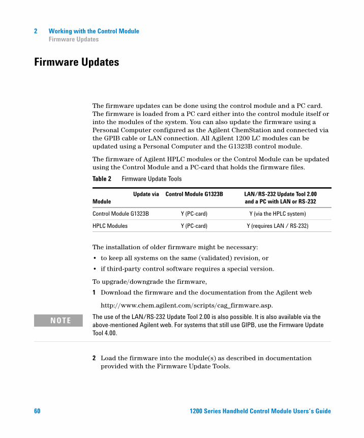
Firmware Updates
The firmware updates can be done using the control module and a PC card.
60
The firmware is loaded from a PC card either into the control module itself or into the modules of the system. You can also update the firmware using a Personal Computer configured as the Agilent ChemStation and connected via the GPIB cable or LAN connection. All Agilent 1200 LC modules can be updated using a Personal Computer and the G1323B control module.
The firmware of Agilent HPLC modules or the Control Module can be updated using the Control Module and a PC-card that holds the firmware files.
The installation of older firmware might be necessary:
• to keep all systems on the same (validated) revision, or
• if third-party control software requires a special version.
To upgrade/downgrade the firmware,
1 Download the firmware and the documentation from the Agilent web
http://www.chem.agilent.com/scripts/cag_firmware.asp.
Table 2 Firmware Update Tools
Update viaModule
Control Module G1323B LAN/RS-232 Update Tool 2.00and a PC with LAN or RS-232
Control Module G1323B Y (PC-card) Y (via the HPLC system)
HPLC Modules Y (PC-card) Y (requires LAN / RS-232)
The use of the LAN/RS-232 Update Tool 2.00 is also possible. It is also available via the
NOTEabove-mentioned Agilent web. For systems that still use GIPB, use the Firmware Update Tool 4.00.2 Load the firmware into the module(s) as described in documentation provided with the Firmware Update Tools.
1200 Series Handheld Control Module Users’s Guide
Working with the Control Module 2Coexecution with Agilent ChemStation
Coexecution with Agilent ChemStation
Features
1200 Series Handhe
• Both user interfaces, the control module and the Agilent ChemStation, can be connected to a Agilent 1200 Series system at the same time.
• Parameter entry is possible from both user interfaces. Parameters will be updated on the other user interface within a few moments.
• An Agilent ChemStation sequence can be stopped and aborted from the control module and vice versa.
• The Agilent ChemStation can generate data files from a control module method or sequence. In this case the pre-fix and file name counter in the Single Sample Info section of the Agilent ChemStation must be enabled (protocol mode only).
• If the control module starts an analysis, the Agilent ChemStation is the slave/monitor system.
In general, however, it is not recommended to run both the Agilent ChemStation and the Control Module at the same time. Since the Agilent ChemStation offers a wider variety of controls over the LC Series system and handling it is much more comfortable it should be preferred over the Control Module. Since problems in diagnosis and verification may occur in some configurations the following restrictions apply:
ld Control Module Users’s Guide 61
2 Working with the Control ModuleCoexecution with Agilent ChemStation
Restrictions
62
• If a parameter window is open for parameter entry on the Agilent ChemStation, this specific entry field is disabled on the control module.
• If an analysis is running with the control module, the Agilent ChemStation should not be turned on or rebooted.
• If the Agilent ChemStation starts an analysis, the control module is the slave/monitor system.
• Parameter changes to a method will be identified on the other user interface as modification.
• The control module and the Agilent ChemStation have a different method handling (Agilent ChemStation method can have more information than the method on the control module, e.g. additional DAD parameters that are only accessible from the Agilent ChemStation). To have a method available on both controllers proceed as follows:
If the method is on the Agilent ChemStation and should be saved on the control module or PC card, load the method on Agilent ChemStation and then save the method on the control module (or PC card) with Method — Save As.
If the method is on the control module or PC card and should be saved on the Agilent ChemStation, first load method DEF_LC.M on the Agilent ChemStation (to have no additional parameter in the format) and then load the required method on control module. Then save the method on the Agilent ChemStation with the same name.
WARNING A method that is available on the control module as protected method can be modified by the Agilent ChemStation and then be saved on the control module without any warning.
1200 Series Handheld Control Module Users’s Guide
Agilent 1200 Series Handheld Control ModuleUser’s Guide
3Using the Pump
Turning the Pump On and Off 64
Entering Settings 64
Purging the Pump 64
Purging Procedure 65
Adjusting Compressibility 66
Adjusting Stroke Volume 68
Automatic Shut-down 68
Troubleshooting the Pump 68
Tracking Pump History / Pump EMF Limits 69
Resetting the Pump 70
Resetting the Pump Settings 70
63Agilent Technologies
3 Using the PumpTurning the Pump On and Off
Turning the Pump On and Off
64
To turn the pump on or off you can use the On/Off button [F7] in the Analysis or System screen:
1 Enter the Analysis or System screen.
2 Select the On/Off button [F7].
3 Select the Pump button [F8].
4 Choose the desired function either with the Action buttons [F6-F8] or by selecting the On/Off buttons in the pop-up window. Uncheck the “to Standby mode only” if you want to turn the pump on or off without going to standby mode.
You can also access this function from the Settings button [F1] available in the Analysis screen or the Control button [F1] in the System screen.
Entering Settings
All pump settings can be entered in the Pump Settings screen. You can access this screen by selecting the Settings button [F1] in the Analysis screen and then choosing the pump. Commonly-used settings such as flow and solvent composition can be set directly in the Analysis screen. The choices available there depend on how many other modules are installed.
Purging the Pump
By opening the purge valve you can redirect the solvent flow from the pump out through the valve exit instead of passing through the injection valve and column. This purging process removes any undegassed or previously used solvent within the pumping system.
1200 Series Handheld Control Module Users’s Guide
Using the Pump 3Purging Procedure
Purging Procedure
1200 Series Handhe
1 Ensure that an outlet tube is connected from the purge valve to a waste solvent bottle.
2 Open the purge valve.
3 Enter the Analysis screen.
4 Set the purge flow rate in the regular flow rate section of the Analysis screen, for example, to 5 ml/min.
NOTE If a flow rate of more than 5 ml/min is used on a quaternary pump, redefine the upper pressure limit to 200 bar (Accessible from the Analysis screen, press the Settings button [F1], choose pump from the list and press the Enter key. Then choose More ...)
5 Set the first channel to be purged to 100%. We recommend you start with the organic solvent channel first. Channel A will automatically be set to 100% when all other channels are set to zero or OFF.
6 Turn on the pump using the On/Off button [F7] in the Analysis screen.
7 Wait until a continuous stream of solvent comes out of the outlet tube from the purge valve.
8 Turn off the pump using the On/Off button [F7] in the Analysis screen and then close the purge valve.
9 Repeat the procedure for the other channels you need to purge.
NOTE The channels of a pumping system are named A, B, C and D (depending on the pump type). %A is automatically calculated by 100% - (%B + %C + %D). If no values for %B, %C and %D are entered, %A is always 100%. To purge the pump you have to go through steps step 5 to step 8 individually for each of the channels, setting the composition to 100% for the channel to be purged.
ld Control Module Users’s Guide 65
3 Using the PumpAdjusting Compressibility
Adjusting Compressibility
66
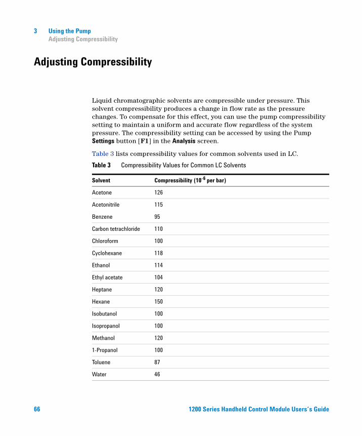
Liquid chromatographic solvents are compressible under pressure. This solvent compressibility produces a change in flow rate as the pressure changes. To compensate for this effect, you can use the pump compressibility setting to maintain a uniform and accurate flow regardless of the system pressure. The compressibility setting can be accessed by using the Pump Settings button [F1] in the Analysis screen.
Table 3 lists compressibility values for common solvents used in LC.
Table 3 Compressibility Values for Common LC Solvents
Solvent Compressibility (10-6 per bar)
Acetone 126
Acetonitrile 115
Benzene 95
Carbon tetrachloride 110
Chloroform 100
Cyclohexane 118
Ethanol 114
Ethyl acetate 104
Heptane 120
Hexane 150
Isobutanol 100
Isopropanol 100
Methanol 120
1-Propanol 100
Toluene 87
Water 46
1200 Series Handheld Control Module Users’s Guide
1200 Series Handhe
Using the Pump 3Adjusting Compressibility
When the compressibility setting is set to Off, the pump makes no compensation for the compressibility of the mobile phase.
For each particular compressibility value, the piston stroke (distance piston moves) and the speed at which the piston moves are adjusted accordingly, compensating for the solvent compressibility. For a mixture of solvents we recommend that you choose the compressibility value of the solvent that is present in the highest amount.
ld Control Module Users’s Guide 67
3 Using the PumpAdjusting Stroke Volume
Adjusting Stroke Volume
68
The stroke volume defines the volume of mobile phase which is displaced by one stroke of pump piston 1. You can set the stroke volume to AUTO (automatic) or a value between 20 and 100 µl. When the stroke is set to AUTO, the pump uses large strokes at high flow and shorter strokes at low flow rate. This can improve the mixing performance and gradient linearity by reducing the size of the solvent packets to be mixed.
The stroke volume can be accessed by using the Settings button [F1] in the Analysis screen, selecting the pump and then pressing More ...
The amplitude of the pressure pulsation is directly proportional to the stroke volume. Decreasing the stroke volume decreases the pulsation amplitude, giving a better signal-to-noise ratio with flow-sensitive detectors. To maintain the flow, the pumping frequency is increased, increasing the frequency of the pressure pulsation. Increasing the pump frequency gives better peak area reproducibility at low flow rates.
Automatic Shut-down
At the end of a sequence you can set the pump to be automatically turned off using the Sequence End Actions button [F1] in the Sequence screen. You can turn off the pump completely or load a specific shut-down method.
Troubleshooting the Pump
1 Select the Tests button [F3] in the System screen.
2 Select Pump from the menu.
You can now select various tests to check the pump. For further information about these tests see the Reference Manual for the Agilent 1200 Series pump.
1200 Series Handheld Control Module Users’s Guide
Using the Pump 3Tracking Pump History / Pump EMF Limits
Tracking Pump History / Pump EMF Limits
1200 Series Handhe
1 Select the Records button [F4] in the System screen.
2 Select Pump from the list.
3 Press Enter.
You can now check the amount of solvent the pump has delivered (liquimeter) and the wear count.
The liquimeter displays the total volume of solvent that the pump has delivered since it was last reset. You can use the liquimeter limit to set up a preventive maintenance schedule for the pump. For example, make a note of the total number of liters pumped when you change the piston seals. This volume is a benchmark, reflecting the lifetime of the seals for your solvents and application. When the limit is exceeded an early maintenance feedback message will appear indicating it is time to change the seals. Changing the seals in advance will prevent you having to repeat analyses, due to leaking seals.
The wear count displays a calculated value indicating the wear of the pump seals. You can also use the seal wear limit to set up a preventive maintenance schedule for changing the pump seals when the limit is exceeded.
ld Control Module Users’s Guide 69
3 Using the PumpResetting the Pump
Resetting the Pump
70
1 Select the Control button [F1] in the System screen.
2 Select Pump from the menu.
3 Press Enter.
4 Select the Reset button [F7] to stop the pump operation and perform a hardware initialization.
Resetting the Pump Settings
1 Select the Settings button [F1] in the Analysis screen.
2 Select Pump from the menu.
3 Press Enter.
4 Select the Default button [F7] to reset the pump settings to their default values.
1200 Series Handheld Control Module Users’s Guide
Agilent 1200 Series Handheld Control ModuleUser’s Guide
4Using the Degasser
Starting the Degasser 72
Removing Gas Bubbles 72
Changing Solvents 73
71Agilent Technologies
4 Using the DegasserStarting the Degasser
Starting the Degasser
72
1 Press the line-power switch on the front panel.
2 Turn on your pump by selecting the On/Off button [F8] in the Analysis screen.
3 Observe the degasser status lamp on the front panel.
The status lamp is off when there is sufficient vacuum in the degasser.
During operation, the status lamp may be yellow for several seconds. This indicates there is insufficient vacuum in the online degasser and the vacuum pump is on to create sufficient vacuum.
Removing Gas Bubbles
If you see gas bubbles in the solvent tubing or inside the solvent filter:
1 Disconnect the solvent tube of the first solvent channel from your pump.
2 Connect the syringe adapter onto the syringe from degasser accessory kit.
3 Pull the syringe plunger to draw solvent through the degasser and tubing. Continue to draw solvent through tubing until no gas bubbles are visible.
4 Disconnect the syringe adapter from the solvent tube.
5 Connect the solvent tube to your pump.
Repeat step 1 through step 5 for other solvent channels.
1200 Series Handheld Control Module Users’s Guide
Using the Degasser 4Changing Solvents
Changing Solvents
1200 Series Handhe
If you are changing to a solvent that is immiscible with the solvent currently in the tubing:
1 Replace the current solvent:
• with iso-propanol, if current solvent is organic, or
• with water, if current solvent is an organic buffer or salt.
2 Flush the online degasser and all tubing thoroughly.
3 Replace the iso-propanol or water with the new solvent.
ld Control Module Users’s Guide 73

74
4 Using the DegasserChanging Solvents
1200 Series Handheld Control Module Users’s Guide

Agilent 1200 Series Handheld Control ModuleUser’s Guide
5Using the Autosampler
Configuring the Autosampler 76
Entering Settings 77
Aligning Transport Arm/Gripper 80
Tracking Autosampler History / EMF limits 81
Resetting the Autosampler 81
Troubleshooting the Autosampler 82
75Agilent Technologies
5 Using the AutosamplerConfiguring the Autosampler
Configuring the Autosampler
76
1 Select the Configure button [F2] in the System screen.
2 Select Autosampler from the menu.
3 Press Enter.
You can configure the syringe volume, seat capillary volume, action on missing vial, trays, interfaces etc.
Configuring Interfaces
1 Select the Configure button [F2] in the System screen.
2 Select Autosampler from the menu.
3 Press Enter.
4 Select the Interfaces button [F1].
5 Select the interfaces you want to operate (see “Connecting External Devices” on page 57).
6 Select the Done button [F6].
1200 Series Handheld Control Module Users’s Guide
Using the Autosampler 5Entering Settings
Entering Settings
1200 Series Handhe
All autosampler settings can be entered in the Autosampler Settings screen. You can access this screen by selecting the Settings button [F1] in the Analysis screen. From here you can access the timetable function (to set up a timetable for the Autosampler only), the runtimes screen and the injector program screen. Commonly-used settings such as injection volume and vial number can be set directly in the Analysis screen. More specific settings (draw speed, eject speed, draw position offset) can be entered using the More... button [F1] and choosing the Settings option.
Setting the Injection Mode
There are two modes which can be set:
• Standard
• without pre-defined needle wash,
• with pre-defined needle wash (wash vial number can be set).
If the pre-defined needle wash function is enabled, the needle moves prior to the injection (with reagent in the needle) into the wash vial to remove sample deposits from the needle outside. This prevents sample stay in the seat and create memory effects on the next injection cycle.
• Injector Program
See “Running an Injector Program” on page 149.
ld Control Module Users’s Guide 77
5 Using the AutosamplerEntering Settings
Optimizing Autosampler Performance
78
There are two optimization modes available on the autosampler (called prefetch and overlap). Both options allow to shorten the analysis time for operations that require a high sample throughput.
The optimization modes can be chosen from the Analysis screen:
1 Press the Settings button [F1].
2 Choose the Autosampler from the list.
3 Select the More... button [F1].
4 Choose Optimization from the list.
5 In the appearing window the optimization mode can be chosen from the list box as well as a delay time.
If you choose the Prefetch Sample Vial option, the next vial (for multiple injections the same vial) will be moved close to the injection port after the specified elapsed runtime. The injection cycle will not be started. This procedure reduces the total injection time without interfering with the current run.
By choosing the Overlap Injection Cycle option the next vial will be placed in the injection port after the selected elapsed runtime. The following restrictions apply when using the Overlap option:
• The elapsed runtime entry before the sample is processed must not interfere with the current running analysis.
• Overlapping works only for a given vial range (e.g. within one sequence line).
• The first run for a new vial range is done without overlap.
• Injector programs using valve switching commands must not be executed when overlapping is selected. They will fail with an error message. Since all injector programs created with the Agilent ChemStation require such commands in order to function correctly, none of them will work in the overlap mode.
The screen also allows you to enable/disable the option ’always keep transport arm next to last used vial’.
1200 Series Handheld Control Module Users’s Guide
Using the Autosampler 5Entering Settings
Setting up the Thermostatted Autosampler
1200 Series Handhe
If a thermostatted autosampler is part of your system you can enter specific setting using the Thermostat option in the settings screen.
Using this option you can set the temperature of the airflow into the autosampler. This setting is available in the Analysis screen, too. Activate the check box to have the temperature controlled as soon as the cooled autosampler is turned on.
Using the More ... option in the Settings screen and selecting Signals you can choose among several thermostat parameters (ambient temperature, heat sink, heat sink fan etc.) that will be referred to as “Autosampler: Auxiliary” in the Plot - Signals screen. This allows you to access a variety of thermostatted autosampler signals without overloading the Available Signals list box (see “Plot Screen” on page 31).
ld Control Module Users’s Guide 79
5 Using the AutosamplerAligning Transport Arm/Gripper
Aligning Transport Arm/Gripper
80
1 Press the Tests button [F3] in the System screen.
2 Choose Autosampler from the list.
3 Press the Align button [F1].
4 Choose Transport.
5 Enter the desired values in the corresponding fields.
The field X Correction sets the default value for the axis parallel to the front panel (left-right motion).
Theta Correction describes the default angle of the transport arm towards the front-back axis of the module (rotation).
For detailed information on the axes consult your Autosampler reference manual.
6 Select the Done button [F6] to accept settings.
The new values will be valid after performing the next hardware initialization or reset.
1200 Series Handheld Control Module Users’s Guide
Using the Autosampler 5Tracking Autosampler History / EMF limits
Tracking Autosampler History / EMF limits
1200 Series Handhe
1 Select the Records button [F4] in the System screen.
2 Select Autosampler from the list.
3 Press Enter.
You can check the number of ’Needle into Seat’ injections the autosampler has made and the number of injection valve cycles. A limit can be specified for each function which you can use to schedule preventive maintenance.
Resetting the Autosampler
1 Select the Control button [F1] in the System screen.
2 Select Autosampler from the menu.
3 Press Enter.
4 Select the Reset button [F7] to reset the autosampler hardware.
This resets the injection valve, metering device and sampling unit.
Reset to Default Settings
1 Select the Settings button [F1] in the Analysis screen.
2 Select Autosampler from the menu.
3 Press Enter.
4 Select the Default button [F7] to reset the autosampler settings to their default values.
ld Control Module Users’s Guide 81
5 Using the AutosamplerTroubleshooting the Autosampler
Troubleshooting the Autosampler
82
1 Select the Tests button [F3] in the System screen.
2 Select Autosampler from the menu.
3 Press Enter.
You can select a variety of injector steps to move individual parts of the autosampler.
The injector step functions can be used in troubleshooting to check the single steps of the injection cycle. For a complete description of each step, see the Reference Manual for the Agilent 1200 Series autosampler.
If you have a thermostatted autosampler, you can also test the auxiliary signals by pressing the Signal button in the Test screen. The auxiliary signals will be displayed graphically now (see “Setting up the Thermostatted Autosampler” on page 79).
1200 Series Handheld Control Module Users’s Guide
Agilent 1200 Series Handheld Control ModuleUser’s Guide
6Using the Manual Injection Valve
About the Injection Valve 84
Making An Injection 85
Completely Filling the Sample Loop 85
Partially Filling the Sample Loop 86
How Much Sample Is Actually Injected? 86
How Much Sample Do I Need? 87
An Alternative Way to Fill The Loop 87
83Agilent Technologies
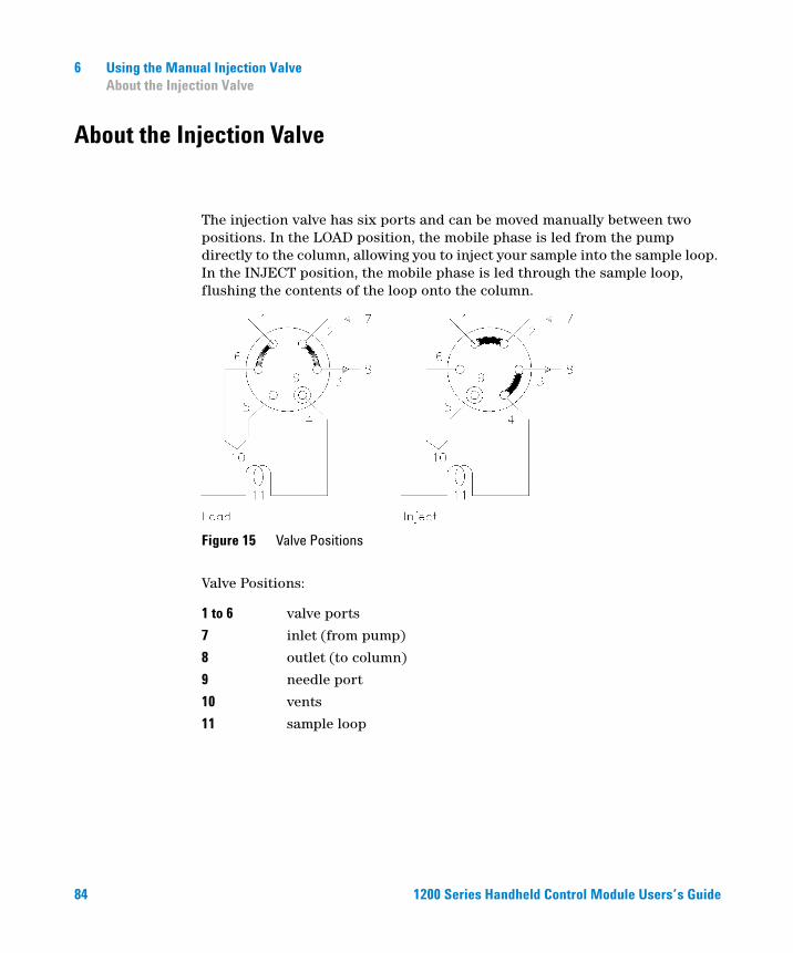
6 Using the Manual Injection ValveAbout the Injection Valve
About the Injection Valve
84
The injection valve has six ports and can be moved manually between two positions. In the LOAD position, the mobile phase is led from the pump directly to the column, allowing you to inject your sample into the sample loop. In the INJECT position, the mobile phase is led through the sample loop, flushing the contents of the loop onto the column.
Valve Positions:
Figure 15 Valve Positions
1 to 6 valve ports
7 inlet (from pump)
8 outlet (to column)
9 needle port
10 vents
11 sample loop
1200 Series Handheld Control Module Users’s Guide
Using the Manual Injection Valve 6Making An Injection
Making An Injection
1200 Series Handhe
The sample loop can be either completely or partially filled. This depends on the amount of sample you have.
Completely Filling the Sample Loop
This is the conventional method in which an excess of sample is used to fill the sample loop completely. The volume of the loop determines the injection volume.
1 Fill syringe with sample.
2 Move valve to LOAD position.
3 Insert needle of syringe into needle port until needle touches stator face. Do not press too hard.
4 Slowly inject sample.
5 Leave syringe in position and move valve to INJECT position.
6 Remove syringe.
ld Control Module Users’s Guide 85
6 Using the Manual Injection ValvePartially Filling the Sample Loop
Partially Filling the Sample Loop
86
Use this method when only small quantities of sample are available. In this method the syringe determines the injection volume.
1 With valve in INJECT position, use needle port cleaner to flush needle port with about 1 ml of mobile phase (this will reduce residual contamination from previous injection).
2 Move valve to LOAD position.
3 Fill syringe with required volume of sample (not more than half of loop volume).
4 Insert needle of syringe into needle port until needle touches stator face. Do not press too hard.
5 Slowly inject sample.
6 Leave syringe in position and move valve to INJECT position.
7 Remove syringe.
How Much Sample Is Actually Injected?
When the sample loop is completely filled, the amount of sample injected is equal to the volume of the sample loop plus the volume of the valve passages (1 in rotor and 2 in stator). This means that the actual amount of sample injected will be different to the nominal value designated to your sample loop. However, since both standards and samples are analyzed using the same loop, you rarely need to know the absolute volume of the loop.
If you do need to know the actual volume of a sample loop, we recommend you calibrate it fitted to the valve, so that you also take the valve passages into account.
1200 Series Handheld Control Module Users’s Guide
Using the Manual Injection Valve 6How Much Sample Do I Need?
How Much Sample Do I Need?
1200 Series Handhe
To completely fill the sample loop an excess of sample is required. This is about 2 to 3 loop volumes of sample to achieve 95 % of the maximum loop volume (the remainder is residual mobile phase in the sample loop). Determine the optimum number of loop volumes experimentally for your particular application.
When you partially fill the sample loop, do not inject more than half of the sample volume. As you inject your sample into the loop, the sample mixes with the solvent already in the loop and some of the sample could be lost through port 6 if you try to inject too much.
An Alternative Way to Fill The Loop
When the sample loop is completely filled you can either inject the sample into the loop or use the syringe to draw the sample through the loop.
1 Move valve to LOAD position.
2 Place vent tube from port 6 into sample vial.
3 Insert needle of syringe into needle port until needle touches stator face. Do not press too hard.
4 Slowly draw sample into syringe.
5 Leave syringe in position and move valve to INJECT position.
6 Remove syringe.
If you use this method, always flush the loading passages (vent tube on port 6) after each injection to prevent cross-contamination between injections. Remember — to flush port 6 and the vent tube, the valve must be in the LOAD position.
ld Control Module Users’s Guide 87

88
6 Using the Manual Injection ValveAn Alternative Way to Fill The Loop
1200 Series Handheld Control Module Users’s Guide

Agilent 1200 Series Handheld Control ModuleUser’s Guide
7Using the Detectors
Turning the Lamp On and Off 90
Entering Settings 91
Resetting the Baseline 93
Configuring the Detector 94
Troubleshooting the Detector 95
Tracking Detector History 96
Resetting the Detector 97
Lamp Ignition Routine (VWD only) 98
Configuring the Analog Channel Output 99
89Agilent Technologies
7 Using the DetectorsTurning the Lamp On and Off
Turning the Lamp On and Off
90
To turn the lamp on and off use the On/Off button [F7] in the Analysis screen:
1 Enter the Analysis screen.
2 Select the On/Off button [F7].
3 Select the Lamp button [F6].
The same can be achieved by using the On/Off button [F8] in the Detector Settings or Control screen available through the Analysis or System screens.
NOTE When the lamp is turned on, a lamp ignition routine is started. For more information “Lamp Ignition Routine (VWD only)” on page 98.
1200 Series Handheld Control Module Users’s Guide
Using the Detectors 7Entering Settings
Entering Settings
1200 Series Handhe
All detector settings can be entered in the Detector Settings screen. You can access this screen by selecting the Settings button [F1] in the Analysis screen and choosing the appropriate detector. Commonly used settings such as wavelength can be set directly in the Analysis screen.
Diode Array Detector
The wavelength for signal A can be entered in the Analysis screen. The sample wavelength, reference wavelength, bandwidth, peakwidth and slit width can be entered in the DA Detector Settings screen. This screen is accessed by selecting the Settings button [F1] in the Analysis screen. Additional entries (autobalance etc.) and the spectrum settings (range, threshold) are accessed by selecting the More... button [F1] under DA Detector Settings.
Variable Wavelength Detector
Settings for this detector include the wavelength, peakwidth and signal polarity. Pressing the More ... button [F1] and choosing Settings you can enter autobalance settings and the margin for negative absorbance. The option Spectrum allows you to enter a wavelength range for a sample spectrum.
Fluorescence Light Detector
For the fluorescence light detector the following settings can be entered: Excitation wavelength, emission wavelength and Multi wavelength settings can be set in the regular Settings screen. With the More ... button [F1] you can specify further detector settings, i.e. peakwidth and PMT-Gain (baseline behaviour, reference, polarity, spectral range fit), multi wavelength settings (spectrum, excitation range), 3D scanning settings (excitation and emission ranges) and phosphorescence detection mode settings.
ld Control Module Users’s Guide 91
7 Using the DetectorsEntering Settings
Multiple Wavelength Detector
92
The wavelength for signal A can be entered in the Analysis screen. The wavelength for signal B, slit width and peak width can be entered in the MW Detector Settings screen. This screen is accessed by selecting the Settings button [F1] in the Analysis screen. Additional signals and functions are accessed by selecting the More... button [F1] under MW Settings.
Refractive Index Detector
NOTE Only the G1323B version of the control module allows control of the Multiple Wavelength Detector. The G1323A will display "resident or unsupported module" if a RI detector is configured in the Agilent 1200 system.
The control module allows to set the RID cell temperature in the Analysis screen.
Temperature, Peakwidth, polarity and automatic recycling can be set in the RI detector settings screen. This screen is accessed by selecting the Settings button [F1] in the Analysis screen.
Automatic zero and automatic purge can be set by selecting the More... button [F1] under RI Settings.
NOTE Only the G1323B version of the control module allows control of the Refractive Index Detector. The G1323A will display "resident or unsupported module" if a RI detector is configured in the Agilent 1200 system.
1200 Series Handheld Control Module Users’s Guide
Using the Detectors 7Resetting the Baseline
Resetting the Baseline
1200 Series Handhe
You can reset the baseline using the Balance button [F1] (Zero button [F1] when using the Refractive Index Detector) in the Detector Control screen. Please note that this procedure is not available for the Fluorescence Light Detector:
1 Select the Control button [F1] in the System screen.
2 Select the Detector from the menu.
3 Press Enter.
4 Select the Balance button [F1].
You can achieve the same using the m (menu) key in the Detector Settings window available from the Analysis screen.
ld Control Module Users’s Guide 93
7 Using the DetectorsConfiguring the Detector
Configuring the Detector
94
1 Select the Configure button [F2] in the System screen.
2 Select the Detector from the list.
3 Press Enter.
You can now configure the detector analog output(s), lamp-on at power-on and the interfaces.
1200 Series Handheld Control Module Users’s Guide
Using the Detectors 7Troubleshooting the Detector
Troubleshooting the Detector
1200 Series Handhe
1 Select the Tests button [F3] in the System screen.
2 Select the Detector from the menu.
3 Press Enter.
4 Select the test you require.
The selection of tests depends on the. For information about each test, see the Reference Manual for the Agilent 1200 detectors.
NOTE The full test capability is only available from the LC ChemStation.
ld Control Module Users’s Guide 95
7 Using the DetectorsTracking Detector History
Tracking Detector History
96
1 Select the Records button [F4] in the System screen.
2 Select the Detector from the menu.
3 Press Enter to display the logbook.
You can check, change and reset the lamp burn time and number of ignitions. For the FL detector the flash lamp lifetime and for the RI detector the time since last purge can be checked.
1200 Series Handheld Control Module Users’s Guide
Using the Detectors 7Resetting the Detector
Resetting the Detector
1200 Series Handhe
1 Select the Settings button [F1] in the Analysis screen.
2 Select the Detector from the menu.
3 Press Enter.
4 Select the Default button [F7] to reset the detector settings to their default values.
ld Control Module Users’s Guide 97
7 Using the DetectorsLamp Ignition Routine (VWD only)
Lamp Ignition Routine (VWD only)
98
When the lamp is turned on, the following routine is implemented:
• 1-minute warm-up, within this time the grating position is re-initialized.
Check of wavelength setting at 656 nm emission (must be within 1 nm) at reference side only (to have no influence from flow cell condition).
If not correct, a message for calibration is displayed. Perform a wavelength calibration (available within VWD Tests).
• Check of intensity
• at 250 nm without cut-off filter inserted,
• at 250 nm with cut-off filter inserted.
If the intensity check is not OK, the cut-off filter operation is not OK.
1200 Series Handheld Control Module Users’s Guide
Using the Detectors 7Configuring the Analog Channel Output
Configuring the Analog Channel Output
1200 Series Handhe
You may use the LC Series 1200 detectors to test or monitor optical parameters on external analog equipment connected via the analog output (Fluorescence Light, Diode Array and Multiple Wavelength Detectors have two analog outputs, Variable Wavelength Detector and Refractive Index Detector have one) at the back side of the module.
To configure the analog outputs:
1 Press the Settings button [F1] in the Analysis screen.
2 Choose the detector and press enter.
3 Press the Analog button [F3].
4 Either select the signal you want to monitor from the signal source drop down list. Or, if you have a variable wavelength detector (fluorescence light detector), choose the signal(s) from the list(s) to be routed to the analog output(s).
5 Enter the values for Zero Offset (sets a baseline offset in order to recognize negative drifts) and Attenuation (sets an absorbance range) for each of the two connectors.
6 Press the Done button [F6].
ld Control Module Users’s Guide 99

100
7 Using the DetectorsConfiguring the Analog Channel Output
1200 Series Handheld Control Module Users’s Guide
Agilent 1200 Series Handheld Control ModuleUser’s Guide
8Using the Column Compartment
Turning the Column Compartment On and Off 102
Entering Settings 103
Configuring the Column Compartment 104
Configuring the Column ID Module 105
Selecting Separated or Combined Mode 106
Selecting the Column Switching Valve (optional) 107
Troubleshooting the Column Compartment 108
Tracking Column Compartment History 109
Tracking Column ID History 110
Resetting the Column Compartment 111
101Agilent Technologies
8 Using the Column CompartmentTurning the Column Compartment On and Off
Turning the Column Compartment On and Off
102
You can turn the column compartment on and off by using the On/Off button [F7] in the Analysis screen:
1 Enter the Analysis screen.
2 Select the On/Off button [F7].
3 Select the Temp button [F7].
The same can be achieved through the Settings or Control buttons [F1] in the Analysis or Systems screens.
1200 Series Handheld Control Module Users’s Guide
Using the Column Compartment 8Entering Settings
Entering Settings
1200 Series Handhe
The temperature can be entered in the Analysis screen. The temperature (for left and/or right heater) can be entered in the Column Compartment Settings screen. This screen is accessed by selecting the Settings button [F1] in the Analysis screen. Additional settings are accessed by selecting the More... button [F1] under Column Compartment Settings.
ld Control Module Users’s Guide 103
8 Using the Column CompartmentConfiguring the Column Compartment
Configuring the Column Compartment
104
1 Select the Configure button [F2] in the System screen.
2 Select Column Comp from the list.
3 PressEnter.
You can now configure the leak-detection mode, temperature-on at power-on, the interfaces and the column identification module.
1200 Series Handheld Control Module Users’s Guide
Using the Column Compartment 8Configuring the Column ID Module
Configuring the Column ID Module
1200 Series Handhe
1 Select the Configure button [F2] in the System screen.
2 Select Column Comp from the list.
3 Press Enter to enter the Column Compartment Configuration screen.
4 Press the Column ID button [F4] to enter Column ID screen.
5 To toggle between left and right column press the Left/Right button [F8].
NOTE If no column tag is sensed, the record fields are not active and the left/right tag sign in the upper right corner or the window is crossed out.
6 Enter your column data into the fields as required. Additional fields are available by pressing the More ... button [F1].
7 Pressing the Write button [F7] will transfer the information into the column tag.
8 Pressing the Right button [F8] will show the information fields of the right column tag (if column is installed).
NOTE The column ID information is updated as soon as a column with ID tag is installed correctly. So you can check the number of injections that have been made on the column in this screen.
ld Control Module Users’s Guide 105
8 Using the Column CompartmentSelecting Separated or Combined Mode
Selecting Separated or Combined Mode
106
This mode allows the temperature setting of both heaters independent from each other. If not enabled both heaters are kept on the same temperature.
1 Select the Settings button [F1] in the Analysis screen.
2 Select Column Comp from the menu.
3 Enable the Separated mode by selecting the check box.
4 To enable the Combined mode, deselect the check box.
1200 Series Handheld Control Module Users’s Guide
Using the Column Compartment 8Selecting the Column Switching Valve (optional)
Selecting the Column Switching Valve (optional)
1200 Series Handhe
The column switching valve is optional.
1 Select the Settings button [F1] in the Analysis screen.
2 Select Column Comp from the menu.
3 Press the Column Switch button.
4 Select mode 1 or 2.
5 Press the Done button [F6] and leave this screen.
ld Control Module Users’s Guide 107
8 Using the Column CompartmentTroubleshooting the Column Compartment
Troubleshooting the Column Compartment
108
1 Select the Tests button [F3] in the System screen.
2 Select Column Comp from the menu.
3 Press Enter.
4 Select the test you require.
You can select the Calibrate test to check the operation of the Column Compartment. For information about the test, see the Reference Manual for the Agilent 1200 Series column compartment.
1200 Series Handheld Control Module Users’s Guide
Using the Column Compartment 8Tracking Column Compartment History
Tracking Column Compartment History
1200 Series Handhe
1 Select the Records button [F2] in the System screen.
2 Select Col. Comp from the list.
3 Press the System or Maint. Log button [F4] to display the logbook.
ld Control Module Users’s Guide 109
8 Using the Column CompartmentTracking Column ID History
Tracking Column ID History
110
1 Select the Configure button [F4] in the System screen.
2 Select Column Comp from the list.
3 Press Enter to enter the Column Compartment Configuration screen.
4 Press the Column ID button [F2] to enter the Column ID screen.
NOTE If no column tag is sensed, the parameter entry fields are not active, the left/right tag sign is crossed out and the More ... button is unavailable.
By selecting the More ... button [F1] you can enter values and check a variety of features for the installed column. For example, the maximum pressure allowed and the maximum recommended temperature.
You can check the number of injections that have been made on the column.
1200 Series Handheld Control Module Users’s Guide
Using the Column Compartment 8Resetting the Column Compartment
Resetting the Column Compartment
1200 Series Handhe
1 Select the Settings button [F1] in the Analysis screen.
2 Select Column Comp from the menu.
3 PressEnter.
4 Select the Default button [F7] to reset the detector settings to their default values.
ld Control Module Users’s Guide 111

112
8 Using the Column CompartmentResetting the Column Compartment
1200 Series Handheld Control Module Users’s Guide
Agilent 1200 Series Handheld Control ModuleUser’s Guide
9Running an Isocratic Analysis
What You Will Need 114
Preparing the LC System 115
Entering Settings 116
Saving Settings in a Method 118
Observing the Chromatogram 119
Starting the Analysis 121
113Agilent Technologies
9 Running an Isocratic AnalysisWhat You Will Need
What You Will Need
Instruments
114
Agilent 1200 Series isocratic, binary or quaternary pump, autosampler and a UV-detector.
Column
A 125 mm × 4.0 mm Hypersil ODS, 5 µm (Agilent Technologies part number 7982618-564).Solvents
For the isocratic pump, a solvent mixture of LC grade bidistilled water (35 %) and acetonitrile (65 %).Sample
The Agilent Technologies isocratic standard sample (Agilent Technologies part number 01080-68704). This contains 0.15 wt.% dimethylphthalate, 0.15 wt% diethylphthalate, 0.01 wt.% biphenyl and 0.03 wt.% o-terphenyl dissolved in methanol.1200 Series Handheld Control Module Users’s Guide
Running an Isocratic Analysis 9Preparing the LC System
Preparing the LC System
1200 Series Handhe
1 For the isocratic pump, fill the solvent bottle with the mixture of LC-grade bidistilled water (35 %) and acetonitrile (65 %). For the binary or quaternary pump, fill one solvent bottle with bidistilled water (channel A) and the other with acetonitrile (channel B).
2 Turn on the detector lamp and pump using the On/Off button [F7] in the Analysis screen. (Use Action keys then to select the module)
3 For the quaternary pump, turn on the degasser by pressing the line-power switch.
4 Purge the pump. For more information see Chapter 3, “Using the Pump”.
5 Allow the detector at least 15 minutes to provide a stable baseline.
6 Fill the contents of a Agilent Technologies isocratic standard sample ampoule into a vial and seal the vial with a cap. Place the vial in position 1 of the autosampler tray.
7 Pump the water/acetonitrile (35/65 %) mobile phase through the column for 10 minutes at a flow rate of 2 ml/min.
ld Control Module Users’s Guide 115
9 Running an Isocratic AnalysisEntering Settings
Entering Settings
116
To set up the isocratic analysis you will set the LC system settings to default and then modify selected settings, the other settings will remain with their default values. You will then save these settings to a method called ISO.
1 Enter the Analysis screen.
2 Set the vial range as 1 to 1.
3 Set the number of injections to 1.
4 Press Enter to skip the method name section.
5 Select the Settings button [F1].
6 Select LC System from the menu.
7 Select the Default button [F7] and select the Yes button to load defaults.
8 Press Esc.
9 Select the Settings button [F1].
10 Select the pump from the menu (either ISO, BIN or QUAT).
11 Press the Pressure button [F3].
12 Enter 400 as the upper pressure limit.
13 Select the Done button [F6].
14 Enter the following values: %B 65, (%C OFF, %D OFF for quarternary pump. If you have a binary pump, set %B to 65.).
15 Set the Flow to 1,5 ml/min.
16 Confirm by selecting “Done” to enter the Analysis screen
17 Enter the values shown in Table 4 in the Analysis screen.
Table 4 Values in Analysis Screen
Setting Value
Detection wavelength 254 nm
Injection volume 1 µl
Stoptime 6 min
1200 Series Handheld Control Module Users’s Guide
Running an Isocratic Analysis 9Entering Settings
NOTE The channels of a pumping system are named A, B, C and D (depending on the pump type). %A is automatically calculated by 100% - (%B + %C + %D). If no values for %B, %C and %D are entered, %A is always 100%.
1200 Series Handheld Control Module Users’s Guide 117
9 Running an Isocratic AnalysisSaving Settings in a Method
Saving Settings in a Method
118
1 Select the Method button [F3] in the Analysis screen.
2 Select the Save As button [F8].
3 Enter the method name as ISO using the selection keys (also see “Specifying a Method Name” on page 42)
4 Press the Done button [F6] to save the method.
5 Press the Esc key to return to the Analysis screen.
1200 Series Handheld Control Module Users’s Guide
Running an Isocratic Analysis 9Observing the Chromatogram
Observing the Chromatogram
1200 Series Handhe
1 Select the Plot button [F6] in the Analysis screen.
2 Press the Select button [F6].
3 Choose a Signal from the Available Signals list box.
4 Press Enter.
NOTE You can choose several signals at a time. The plot function will display all signals that are shown in the Selected Signals list box. Use the selection keys to navigate within the list boxes and press the Enter key to move Signals from one box to the other.
5 Select the Done button [F6] to display the chromatogram.
6 Press the Esc key to go back to the Analysis screen.
7 Press the Start button [F8].
8 Select OK to confirm the vial range and injection number and press Enter to start the analysis.
ld Control Module Users’s Guide 119
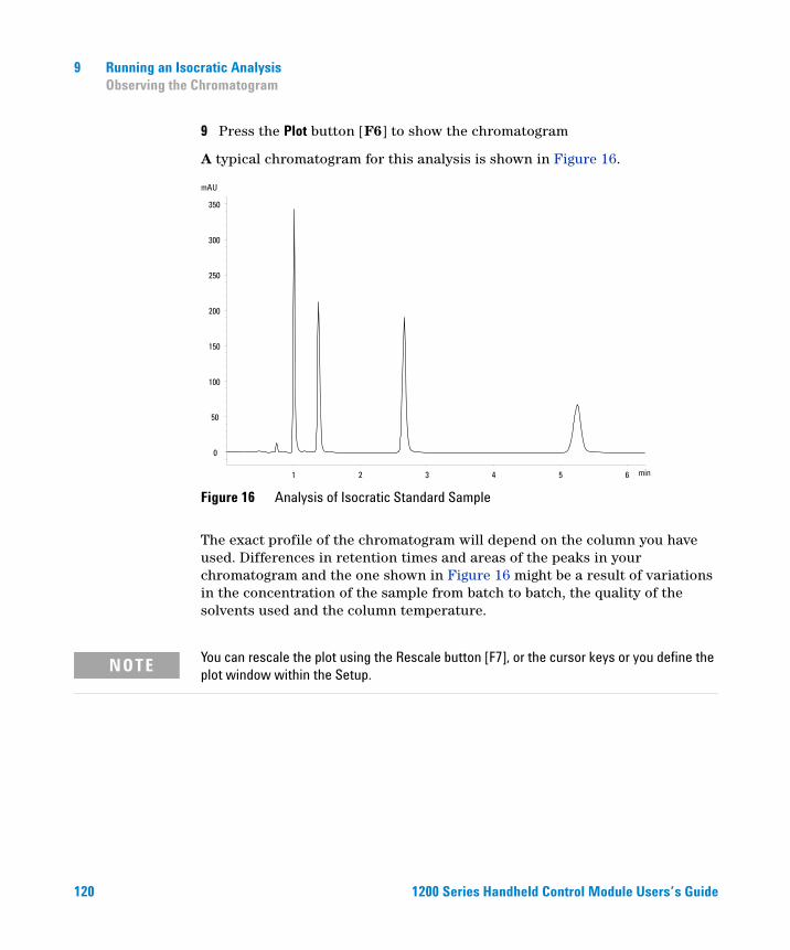
120
9 Running an Isocratic AnalysisObserving the Chromatogram
9 Press the Plot button [F6] to show the chromatogram
A typical chromatogram for this analysis is shown in Figure 16.
The exact profile of the chromatogram will depend on the column you have used. Differences in retention times and areas of the peaks in your chromatogram and the one shown in Figure 16 might be a result of variations in the concentration of the sample from batch to batch, the quality of the solvents used and the column temperature.
Figure 16 Analysis of Isocratic Standard Sample
min1 2 3 4 5 6
mAU
0
50
100
150
200
250
300
350
NOTE You can rescale the plot using the Rescale button [F7], or the cursor keys or you define the plot window within the Setup.
1200 Series Handheld Control Module Users’s Guide
Running an Isocratic Analysis 9Starting the Analysis
Starting the Analysis
NOTE The analysis can be started from various other screens, e.g. System, Status, Sampels or Sequence screen.
1200 Series Handhe
1 Enter the Analysis screen.
2 Select the Start button [F8].
3 Select OK to confirm the vial range and injection number and press the Enter key to start the analysis.
ld Control Module Users’s Guide 121

122
9 Running an Isocratic AnalysisStarting the Analysis
1200 Series Handheld Control Module Users’s Guide
Agilent 1200 Series Handheld Control ModuleUser’s Guide
10Running a Gradient Analysis
What You Will Need 124
Preparing the LC System 125
Entering Settings 126
Saving Settings in a Method 128
Observing the Chromatogram 129
Starting the Analysis 131
123Agilent Technologies
10 Running a Gradient AnalysisWhat You Will Need
What You Will Need
Instruments
124
Agilent 1200 Series binary or quaternary pump, autosampler, UV-detector and degasser.
Column
A 125 mm × 4.0 mm Hypersil ODS, 5 µm (Agilent Technologies part number 7982618-564).Solvents
LC-grade bidistilled water and acetonitrile.Sample
The Agilent Technologies isocratic standard sample (Agilent Technologies part number 01080-68704). This contains 0.15 wt.% dimethylphthalate, 0.15 wt% diethylphthalate, 0.01 wt.% biphenyl and 0.03 wt.% o-terphenyl dissolved in methanol.1200 Series Handheld Control Module Users’s Guide
Running a Gradient Analysis 10Preparing the LC System
Preparing the LC System
1200 Series Handhe
1 Fill one solvent bottle with bidistilled water (channel A) and the other with acetonitrile (channel B).
2 Turn on the detector lamp and pump using the On/Off button [F7] in the Analysis screen.
3 For the quaternary pump, turn on the degasser by pressing the line-power switch.
4 Purge the pump. For more information see Chapter 3, “Using the Pump”.
5 Allow the detector at least 15 minutes to provide a stable baseline.
6 Fill the contents of a Agilent Technologies isocratic standard sample ampoule into a vial and seal the vial with a cap. Place the vial in position 1 of the autosampler tray.
7 Pump the water/acetonitrile (35/65 %) mobile phase through the column for 10 minutes at a flow rate of 2 ml/min.
ld Control Module Users’s Guide 125
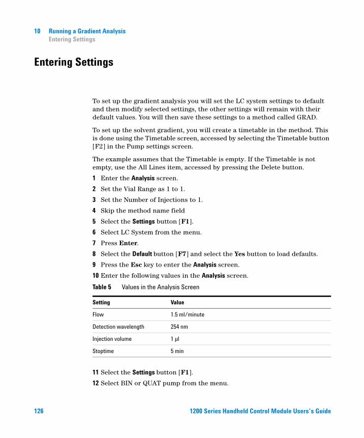
10 Running a Gradient AnalysisEntering Settings
Entering Settings
126
To set up the gradient analysis you will set the LC system settings to default and then modify selected settings, the other settings will remain with their default values. You will then save these settings to a method called GRAD.
To set up the solvent gradient, you will create a timetable in the method. This is done using the Timetable screen, accessed by selecting the Timetable button [F2] in the Pump settings screen.
The example assumes that the Timetable is empty. If the Timetable is not empty, use the All Lines item, accessed by pressing the Delete button.
1 Enter the Analysis screen.
2 Set the Vial Range as 1 to 1.
3 Set the Number of Injections to 1.
4 Skip the method name field
5 Select the Settings button [F1].
6 Select LC System from the menu.
7 Press Enter.
8 Select the Default button [F7] and select the Yes button to load defaults.
9 Press the Esc key to enter the Analysis screen.
10 Enter the following values in the Analysis screen.
11 Select the Settings button [F1].
12 Select BIN or QUAT pump from the menu.
Table 5 Values in the Analysis Screen
Setting Value
Flow 1.5 ml/minute
Detection wavelength 254 nm
Injection volume 1 µl
Stoptime 5 min
1200 Series Handheld Control Module Users’s Guide
1200 Series Handhe
Running a Gradient Analysis 10Entering Settings
If you have a quaternary pump set %B to 65, %C and %D to OFF.
If you have a binary pump set %B to 65.
NOTE The channels of a pumping system are named A, B, C and D (depending on the pump type). %A is automatically calculated by 100% - (%B + %C + %D). If no values for %B, %C and %D are entered, %A is always 100%.
13 Select the Pressure button.
14 Set the upper pressure limit to 400 bar.
15 Select the Done button.
16 Select the Timetable button.
17 Select the Insert button.
18 Enter a value of 2 minutes and select Composition as the setting.
If you have a quaternary pump, set the %B composition to 65, %C and %D to 0.00.
If you have a binary pump, set the %B composition to 65.
19 Select the Enter button to accept entries (Action Key F7).
20 Enter the following information for another two lines.
time 4 : %B = 95
time 5 : %B = 65
21 Press the Done button and verify your timetable entries.
22 Press the Esc key until you are in the Analysis screen.
NOTE Use Enter to store timetable lines.Use Done when all lines have been entered.By pressing the Esc key you return to the previous screen.
ld Control Module Users’s Guide 127
10 Running a Gradient AnalysisSaving Settings in a Method
Saving Settings in a Method
128
1 Select the Method button [F3] in the Analysis screen.
2 Select the Save As button [F8].
3 Enter the method name as GRAD using the selection keys (also see “Specifying a Method Name” on page 42)
4 Press the Done button [F6] to save the method.
5 Press ESC to return to the Analysis screen.
1200 Series Handheld Control Module Users’s Guide
Running a Gradient Analysis 10Observing the Chromatogram
Observing the Chromatogram
1200 Series Handhe
1 Select the Plot button [F6] in the Analysis screen.
2 Press the Select button [F6].
3 Choose a Signal from the Available Signals list box.
4 Press Enter.
NOTE You can choose several signals at a time. The plot function will display all signals that are shown in the Selected Signals list box. Use the selection keys to navigate within the list boxes and press the Enter key to move Signals from one box to the other.
5 Select the Done button [F6] to display the chromatogram.
6 Press Esc to go back to the Analysis screen.
7 Press the Start button [F8].
8 Select OK to confirm the vial range and injection number and press Enter to start the analysis.
ld Control Module Users’s Guide 129
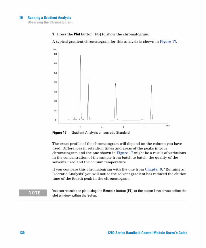
130
10 Running a Gradient AnalysisObserving the Chromatogram
9 Press the Plot button [F6] to show the chromatogram.
A typical gradient chromatogram for this analysis is shown in Figure 17.
The exact profile of the chromatogram will depend on the column you have used. Differences in retention times and areas of the peaks in your chromatogram and the one shown in Figure 17 might be a result of variations in the concentration of the sample from batch to batch, the quality of the solvents used and the column temperature.
If you compare this chromatogram with the one from Chapter 9, “Running an Isocratic Analysis” you will notice the solvent gradient has reduced the elution time of the fourth peak in the chromatogram.
Figure 17 Gradient Analysis of Isocratic Standard
min1 2 3 4
mAU
0
50
100
150
200
250
300
350
NOTE You can rescale the plot using the Rescale button [F7], or the cursor keys or you define the plot window within the Setup.
1200 Series Handheld Control Module Users’s Guide
Running a Gradient Analysis 10Starting the Analysis
Starting the Analysis
NOTE The analysis can be started by pressing the Start button [F8] from the Samples screen, the System screen, or the Status screen.
1200 Series Handhe
1 Enter the Analysis screen.
2 Select the Start button [F8].
3 Select OK to confirm the vial range and injection number and press Enter to start the analysis.
ld Control Module Users’s Guide 131

132
10 Running a Gradient AnalysisStarting the Analysis
1200 Series Handheld Control Module Users’s Guide
Agilent 1200 Series Handheld Control ModuleUser’s Guide
11Running Multiple-Vial Analyses
Analyzing Multiple Vials Using the Same Method 134
Analyzing Multiple Vials Using Different Methods 135
Single-Level Calibration Sequences 137
Multiple-Level Calibration Sequences 139
Recalibrating With the Same Group of Standards 139
Recalibrating With Multiple Groups of Standards 141
Synchronizing Analyses with External Devices 144
133Agilent Technologies
11 Running Multiple-Vial AnalysesAnalyzing Multiple Vials Using the Same Method
Analyzing Multiple Vials Using the Same Method
134
This section describes how to set up a 25-vial analysis with one injection from each vial. You will use a previously created method. The samples are located in positions 1 to 25 of the autosampler tray. For details “Working with Methods” on page 41.
1 Enter the Analysis screen.
2 Set the Vial Range from 1 to 25.
3 Set the number of injections to 1.
4 Select the method you want to use with the scroll buttons ( ).
5 Select the Start button [F8].
6 Select OK to confirm the vial range and injection number and press Enter to start the analysis.
1200 Series Handheld Control Module Users’s Guide
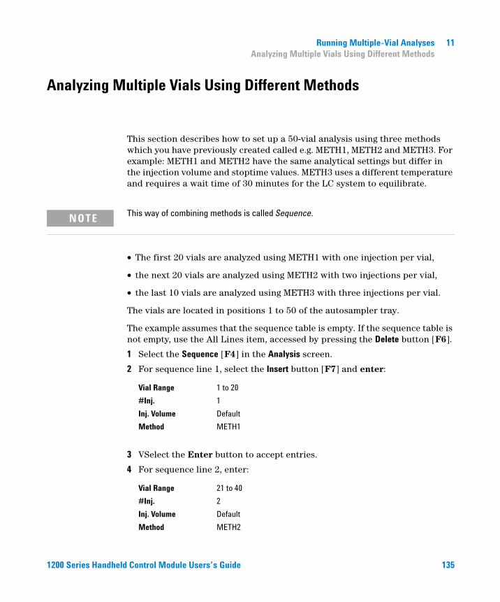
Running Multiple-Vial Analyses 11Analyzing Multiple Vials Using Different Methods
Analyzing Multiple Vials Using Different Methods
1200 Series Handhe
This section describes how to set up a 50-vial analysis using three methods which you have previously created called e.g. METH1, METH2 and METH3. For example: METH1 and METH2 have the same analytical settings but differ in the injection volume and stoptime values. METH3 uses a different temperature and requires a wait time of 30 minutes for the LC system to equilibrate.
NOTE This way of combining methods is called Sequence.
• The first 20 vials are analyzed using METH1 with one injection per vial,
• the next 20 vials are analyzed using METH2 with two injections per vial,
• the last 10 vials are analyzed using METH3 with three injections per vial.
The vials are located in positions 1 to 50 of the autosampler tray.
The example assumes that the sequence table is empty. If the sequence table is not empty, use the All Lines item, accessed by pressing the Delete button [F6].
1 Select the Sequence [F4] in the Analysis screen.
2 For sequence line 1, select the Insert button [F7] and enter:
3 VSelect the Enter button to accept entries.
4 For sequence line 2, enter:
Vial Range 1 to 20
#Inj. 1
Inj. Volume Default
Method METH1
Vial Range 21 to 40
#Inj. 2
Inj. Volume Default
Method METH2
ld Control Module Users’s Guide 135
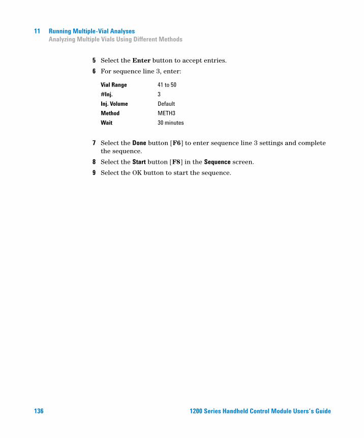
136
11 Running Multiple-Vial AnalysesAnalyzing Multiple Vials Using Different Methods
5 Select the Enter button to accept entries.
6 For sequence line 3, enter:
7 Select the Done button [F6] to enter sequence line 3 settings and complete the sequence.
8 Select the Start button [F8] in the Sequence screen.
9 Select the OK button to start the sequence.
Vial Range 41 to 50
#Inj. 3
Inj. Volume Default
Method METH3
Wait 30 minutes
1200 Series Handheld Control Module Users’s Guide
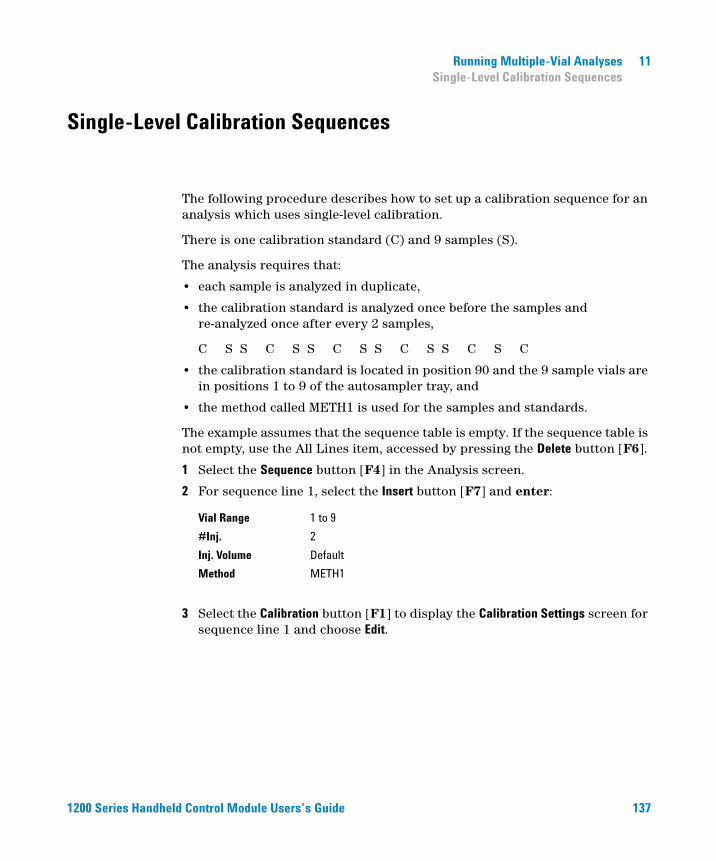
Running Multiple-Vial Analyses 11Single-Level Calibration Sequences
Single-Level Calibration Sequences
1200 Series Handhe
The following procedure describes how to set up a calibration sequence for an analysis which uses single-level calibration.
There is one calibration standard (C) and 9 samples (S).
The analysis requires that:
• each sample is analyzed in duplicate,
• the calibration standard is analyzed once before the samples and re-analyzed once after every 2 samples,
C S S C S S C S S C S S C S C
• the calibration standard is located in position 90 and the 9 sample vials are in positions 1 to 9 of the autosampler tray, and
• the method called METH1 is used for the samples and standards.
The example assumes that the sequence table is empty. If the sequence table is not empty, use the All Lines item, accessed by pressing the Delete button [F6].
1 Select the Sequence button [F4] in the Analysis screen.
2 For sequence line 1, select the Insert button [F7] and enter:
3 Select the Calibration button [F1] to display the Calibration Settings screen for sequence line 1 and choose Edit.
Vial Range 1 to 9
#Inj. 2
Inj. Volume Default
Method METH1
ld Control Module Users’s Guide 137
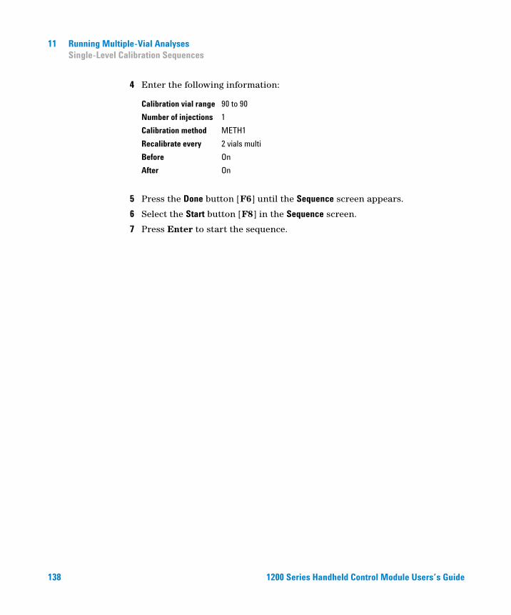
138
11 Running Multiple-Vial AnalysesSingle-Level Calibration Sequences
4 Enter the following information:
5 Press the Done button [F6] until the Sequence screen appears.
6 Select the Start button [F8] in the Sequence screen.
7 Press Enter to start the sequence.
Calibration vial range 90 to 90
Number of injections 1
Calibration method METH1
Recalibrate every 2 vials multi
Before On
After On
1200 Series Handheld Control Module Users’s Guide
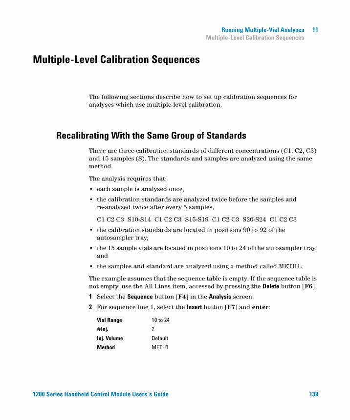
Running Multiple-Vial Analyses 11Multiple-Level Calibration Sequences
Multiple-Level Calibration Sequences
1200 Series Handhe
The following sections describe how to set up calibration sequences for analyses which use multiple-level calibration.
Recalibrating With the Same Group of Standards
There are three calibration standards of different concentrations (C1, C2, C3) and 15 samples (S). The standards and samples are analyzed using the same method.
The analysis requires that:
• each sample is analyzed once,
• the calibration standards are analyzed twice before the samples and re-analyzed twice after every 5 samples,
C1 C2 C3 S10-S14 C1 C2 C3 S15-S19 C1 C2 C3 S20-S24 C1 C2 C3
• the calibration standards are located in positions 90 to 92 of the autosampler tray,
• the 15 sample vials are located in positions 10 to 24 of the autosampler tray, and
• the samples and standard are analyzed using a method called METH1.
The example assumes that the sequence table is empty. If the sequence table is not empty, use the All Lines item, accessed by pressing the Delete button [F6].
1 Select the Sequence button [F4] in the Analysis screen.
2 For sequence line 1, select the Insert button [F7] and enter:
Vial Range 10 to 24
#Inj. 2
Inj. Volume Default
Method METH1
ld Control Module Users’s Guide 139
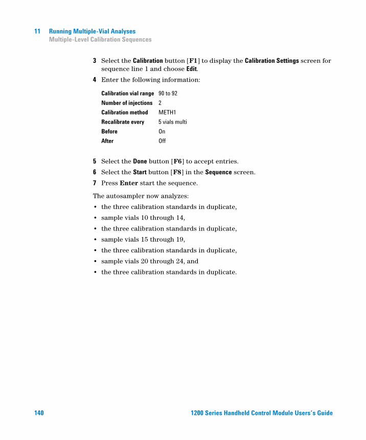
140
11 Running Multiple-Vial AnalysesMultiple-Level Calibration Sequences
3 Select the Calibration button [F1] to display the Calibration Settings screen for sequence line 1 and choose Edit.
4 Enter the following information:
5 Select the Done button [F6] to accept entries.
6 Select the Start button [F8] in the Sequence screen.
7 Press Enter start the sequence.c
The autosampler now analyzes:
• the three calibration standards in duplicate,
• sample vials 10 through 14,
• the three calibration standards in duplicate,
• sample vials 15 through 19,
• the three calibration standards in duplicate,
• sample vials 20 through 24, and
• the three calibration standards in duplicate.
Calibration vial range 90 to 92
Number of injections 2
Calibration method METH1
Recalibrate every 5 vials multi
Before On
After Off
1200 Series Handheld Control Module Users’s Guide
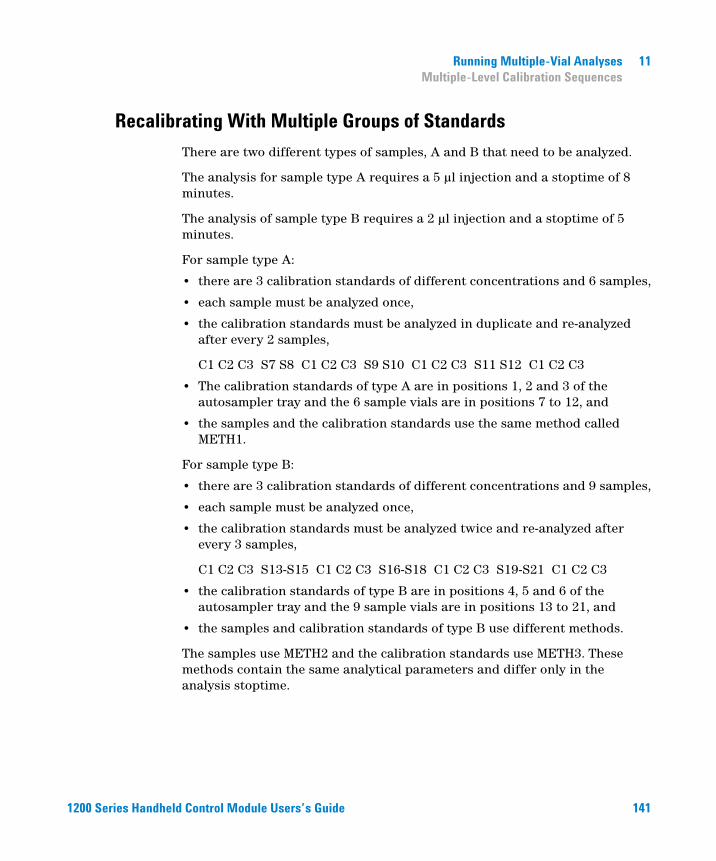
Running Multiple-Vial Analyses 11Multiple-Level Calibration Sequences
Recalibrating With Multiple Groups of Standards
1200 Series Handhe
There are two different types of samples, A and B that need to be analyzed.
The analysis for sample type A requires a 5 µl injection and a stoptime of 8 minutes.
The analysis of sample type B requires a 2 µl injection and a stoptime of 5 minutes.
For sample type A:
• there are 3 calibration standards of different concentrations and 6 samples,
• each sample must be analyzed once,
• the calibration standards must be analyzed in duplicate and re-analyzed after every 2 samples,
C1 C2 C3 S7 S8 C1 C2 C3 S9 S10 C1 C2 C3 S11 S12 C1 C2 C3
• The calibration standards of type A are in positions 1, 2 and 3 of the autosampler tray and the 6 sample vials are in positions 7 to 12, and
• the samples and the calibration standards use the same method called METH1.
For sample type B:
• there are 3 calibration standards of different concentrations and 9 samples,
• each sample must be analyzed once,
• the calibration standards must be analyzed twice and re-analyzed after every 3 samples,
C1 C2 C3 S13-S15 C1 C2 C3 S16-S18 C1 C2 C3 S19-S21 C1 C2 C3
• the calibration standards of type B are in positions 4, 5 and 6 of the autosampler tray and the 9 sample vials are in positions 13 to 21, and
• the samples and calibration standards of type B use different methods.
The samples use METH2 and the calibration standards use METH3. These methods contain the same analytical parameters and differ only in the analysis stoptime.
ld Control Module Users’s Guide 141
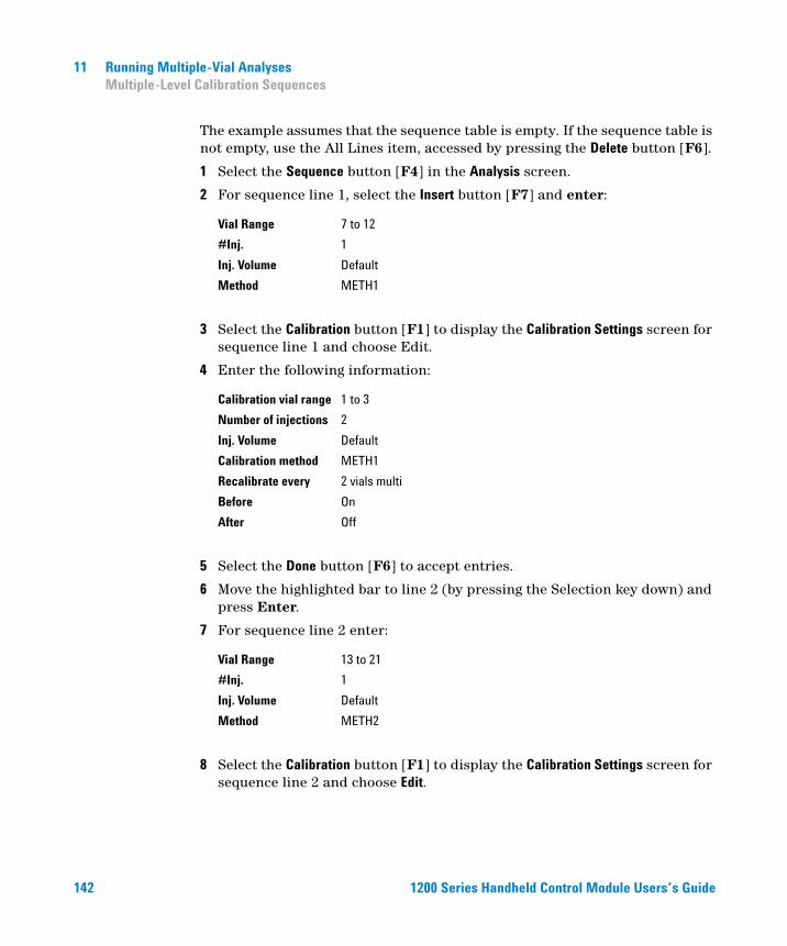
142
11 Running Multiple-Vial AnalysesMultiple-Level Calibration Sequences
The example assumes that the sequence table is empty. If the sequence table is not empty, use the All Lines item, accessed by pressing the Delete button [F6].
1 Select the Sequence button [F4] in the Analysis screen.
2 For sequence line 1, select the Insert button [F7] and enter:
3 Select the Calibration button [F1] to display the Calibration Settings screen for sequence line 1 and choose Edit.
4 Enter the following information:
5 Select the Done button [F6] to accept entries.
6 Move the highlighted bar to line 2 (by pressing the Selection key down) and press Enter.
7 For sequence line 2 enter:
8 Select the Calibration button [F1] to display the Calibration Settings screen for sequence line 2 and choose Edit.
Vial Range 7 to 12
#Inj. 1
Inj. Volume Default
Method METH1
Calibration vial range 1 to 3
Number of injections 2
Inj. Volume Default
Calibration method METH1
Recalibrate every 2 vials multi
Before On
After Off
Vial Range 13 to 21
#Inj. 1
Inj. Volume Default
Method METH2
1200 Series Handheld Control Module Users’s Guide
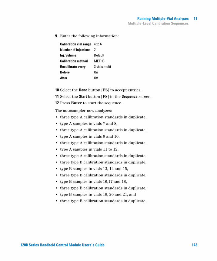
1200 Series Handhe
Running Multiple-Vial Analyses 11Multiple-Level Calibration Sequences
9 Enter the following information:
10 Select the Done button [F6] to accept entries.
11 Select the Start button [F8] in the Sequence screen.
12 Press Enter to start the sequence.
The autosampler now analyzes:
• three type A calibration standards in duplicate,
• type A samples in vials 7 and 8,
• three type A calibration standards in duplicate,
• type A samples in vials 9 and 10,
• three type A calibration standards in duplicate,
• type A samples in vials 11 to 12,
• three type A calibration standards in duplicate,
• three type B calibration standards in duplicate,
• type B samples in vials 13, 14 and 15,
• three type B calibration standards in duplicate,
• type B samples in vials 16,17 and 18,
• three type B calibration standards in duplicate,
• type B samples in vials 19, 20 and 21, and
• three type B calibration standards in duplicate.
Calibration vial range 4 to 6
Number of injections 2
Inj. Volume Default
Calibration method METH3
Recalibrate every 3 vials multi
Before On
After Off
ld Control Module Users’s Guide 143
11 Running Multiple-Vial AnalysesSynchronizing Analyses with External Devices
Synchronizing Analyses with External Devices
144
With an APG remote connector the system can be connected to external devices in order to synchronize the analyses. This is necessary when an external device needs some time in order to get ready for a new analysis and when transmitting of a start request is required (see “Connecting External Devices” on page 57 for further information on interfaces).
When executing an analysis by pressing the Start button [F8] you will see a window where sequence modes can be chosen.
In any case, do all the analysis preparation using the control module.
Standard
NOTE A “Start” command is used to start the analytical run from the point of injection and is usually issued by the autosampler.A “Start Request” command causes the autosampler to take the next vial and place it under the injection needle (also see “APG Remote” on page 57 and “Optimizing Autosampler Performance” on page 78)The “Start button” [F8] on the control module is used to start a vial range or sequence analysis.
In the standard mode the analysis is under the command of the control module. The control module will issue a Start Request command to the autosampler as soon as all modules are ready for the next analysis. The autosampler issues the Start command at the point of injection. With an Agilent 1200 Autosampler integrated in the system and no external devices this is the normal operation mode.
1200 Series Handheld Control Module Users’s Guide
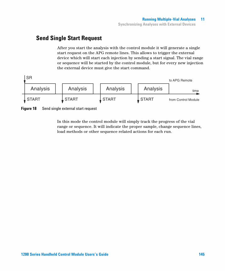
Running Multiple-Vial Analyses 11Synchronizing Analyses with External Devices
Send Single Start Request
1200 Series Handhe
After you start the analysis with the control module it will generate a single start request on the APG remote lines. This allows to trigger the external device which will start each injection by sending a start signal. The vial range or sequence will be started by the control module, but for every new injection the external device must give the start command.
Figure 18 Send single external start request
In this mode the control module will simply track the progress of the vial range or sequence. It will indicate the proper sample, change sequence lines, load methods or other sequence related actions for each run.
ld Control Module Users’s Guide 145
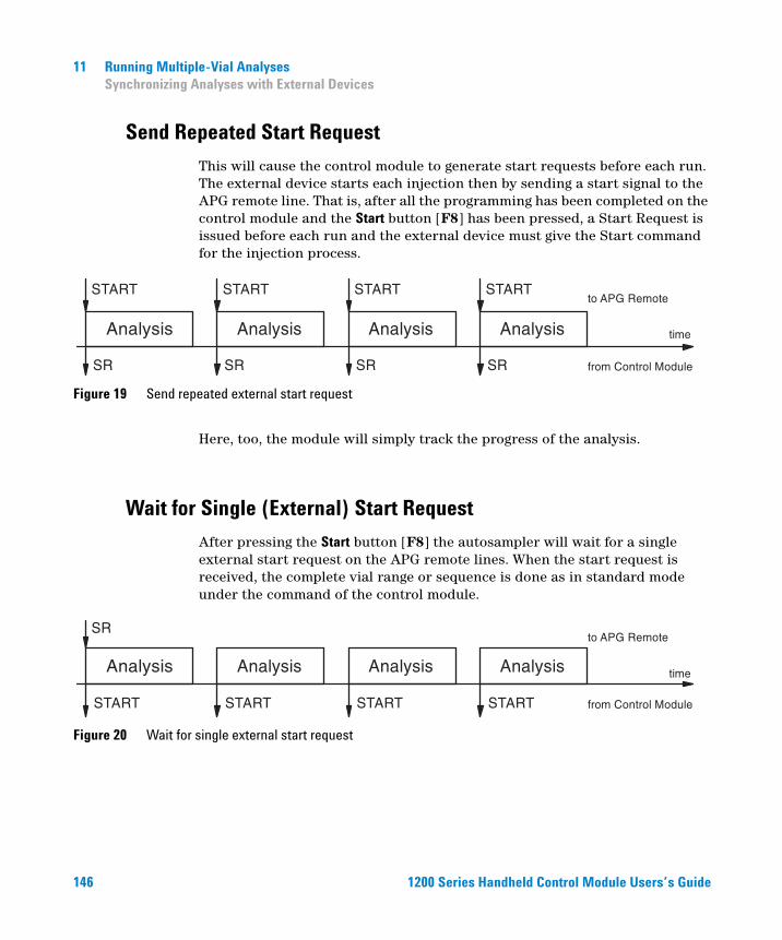
11 Running Multiple-Vial AnalysesSynchronizing Analyses with External Devices
Send Repeated Start Request
146
This will cause the control module to generate start requests before each run. The external device starts each injection then by sending a start signal to the APG remote line. That is, after all the programming has been completed on the control module and the Start button [F8] has been pressed, a Start Request is issued before each run and the external device must give the Start command for the injection process.
Figure 19 Send repeated external start request
Here, too, the module will simply track the progress of the analysis.
Wait for Single (External) Start Request
After pressing the Start button [F8] the autosampler will wait for a single external start request on the APG remote lines. When the start request is received, the complete vial range or sequence is done as in standard mode under the command of the control module.
Figure 20 Wait for single external start request
1200 Series Handheld Control Module Users’s Guide
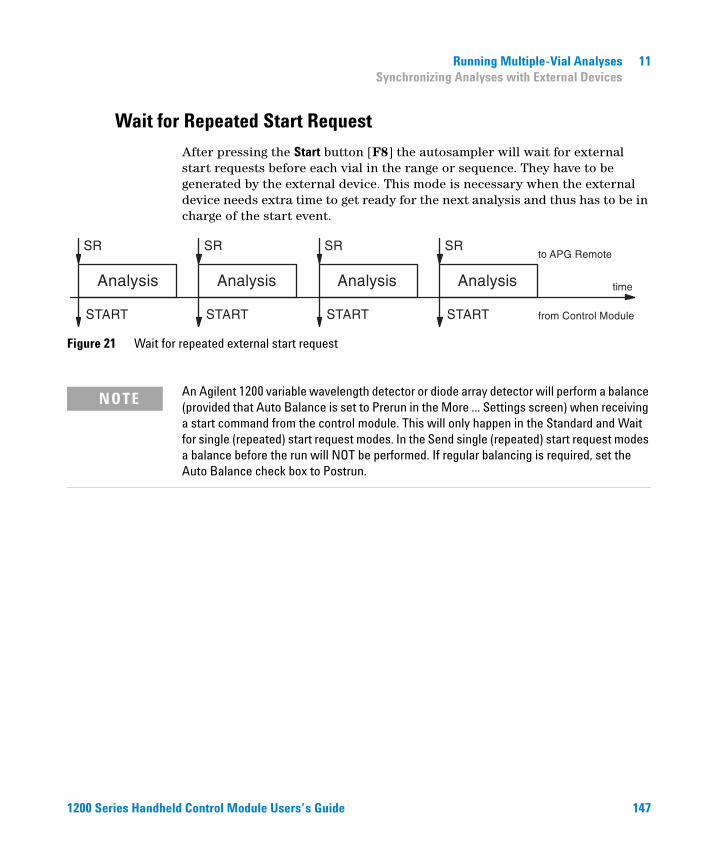
Running Multiple-Vial Analyses 11Synchronizing Analyses with External Devices
Wait for Repeated Start Request
1200 Series Handhe
After pressing the Start button [F8] the autosampler will wait for external start requests before each vial in the range or sequence. They have to be generated by the external device. This mode is necessary when the external device needs extra time to get ready for the next analysis and thus has to be in charge of the start event.
Figure 21 Wait for repeated external start request
NOTE An Agilent 1200 variable wavelength detector or diode array detector will perform a balance (provided that Auto Balance is set to Prerun in the More ... Settings screen) when receiving a start command from the control module. This will only happen in the Standard and Wait for single (repeated) start request modes. In the Send single (repeated) start request modes a balance before the run will NOT be performed. If regular balancing is required, set the Auto Balance check box to Postrun.
ld Control Module Users’s Guide 147

148
11 Running Multiple-Vial AnalysesSynchronizing Analyses with External Devices
1200 Series Handheld Control Module Users’s Guide
Agilent 1200 Series Handheld Control ModuleUser’s Guide
12Running an Injector Program
Creating an Injector Program 150
Entering Injector Program Settings 151
Saving the Method 153
149Agilent Technologies
12 Running an Injector ProgramCreating an Injector Program
Creating an Injector Program
150
The injector program is part of the method. The injector program screen can be accessed using the Inj. Program button [F3] in the Autosampler Settings screen.
This section describes an injector program to do sample preparation involving a precolumn derivatization reaction. This is required when the analytes lack chromophores and in their original chemical structure cannot be detected with the required sensitivity.
To create this injector program you will:
• set the LC system to the default settings
• modify the injector program settings in the Inj. Program screen, the other settings will remain with their default values, and
• save the method with the name DERIV.
When the method called DERIV is started, the program is executed followed by the analytical run.
The first step of the program involves drawing derivatization reagent into the needle capillary, followed by sample and then reagent again. To ensure the reagent and sample react efficiently, the plunger in the metering device of the autosampler is moved back and forth. This mixes the sample and reagent as they travel up and down the capillary. Following mixing, the derivatization requires a pause to allow the sample and reagent to fully react, before the derivatized sample is injected onto the column.
1200 Series Handheld Control Module Users’s Guide
Running an Injector Program 12Entering Injector Program Settings
Entering Injector Program Settings
1200 Series Handhe
1 Enter the Analysis screen.
2 Select the Settings button [F1].
3 Select LC System from the menu.
4 Select the Default button [F6] and select the Yes button to load defaults.
5 Press Esc to go back to the Analysis menu.
6 Select the Settings button [F1].
7 Select Autosampler from the menu.
8 Select the Inj.Program button [F3] to display the Program screen.
9 For program line 1, select the Insert button [F7].
10 Select the DRAW function and enter the draw settings as described in Table 6 on page 152.
11 Select the Enter button [F7] to accept entries.
12 Repeat the procedure for the other functions to complete the program.
13 Press the Esc key until you are back in the Settings screen.
ld Control Module Users’s Guide 151
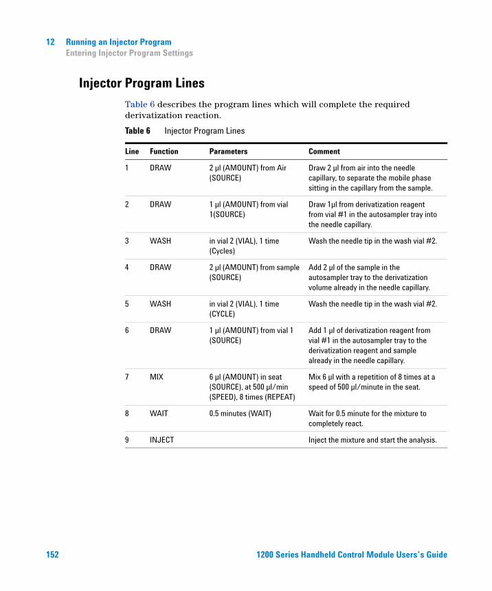
12 Running an Injector ProgramEntering Injector Program Settings
Injector Program Lines
152
Table 6 describes the program lines which will complete the required derivatization reaction.
Table 6 Injector Program Lines
Line Function Parameters Comment
1 DRAW 2 µl (AMOUNT) from Air (SOURCE)
Draw 2 µl from air into the needle capillary, to separate the mobile phase sitting in the capillary from the sample.
2 DRAW 1 µl (AMOUNT) from vial 1(SOURCE)
Draw 1µl from derivatization reagent from vial #1 in the autosampler tray into the needle capillary.
3 WASH in vial 2 (VIAL), 1 time (Cycles)
Wash the needle tip in the wash vial #2.
4 DRAW 2 µl (AMOUNT) from sample (SOURCE)
Add 2 µl of the sample in the autosampler tray to the derivatization volume already in the needle capillary.
5 WASH in vial 2 (VIAL), 1 time (CYCLE)
Wash the needle tip in the wash vial #2.
6 DRAW 1 µl (AMOUNT) from vial 1 (SOURCE)
Add 1 µl of derivatization reagent from vial #1 in the autosampler tray to the derivatization reagent and sample already in the needle capillary.
7 MIX 6 µl (AMOUNT) in seat (SOURCE), at 500 µl/min (SPEED), 8 times (REPEAT)
Mix 6 µl with a repetition of 8 times at a speed of 500 µl/minute in the seat.
8 WAIT 0.5 minutes (WAIT) Wait for 0.5 minute for the mixture to completely react.
9 INJECT Inject the mixture and start the analysis.
1200 Series Handheld Control Module Users’s Guide
Running an Injector Program 12Saving the Method
Saving the Method
1200 Series Handhe
1 Select the Method button [F3] in the Analysis screen.
2 Select the Save As button [F8].
3 Enter the method name as DERIV using the selection keys (also see “Specifying a Method Name” on page 42)
4 Press the Done button [F6] to save the method.
5 Press the Esc key to return to the Analysis screen.
The injector program is now part of the method called DERIV and can be started by selecting the Start button [F8] in the Analysis screen.
ld Control Module Users’s Guide 153

154
12 Running an Injector ProgramSaving the Method
1200 Series Handheld Control Module Users’s Guide
Agilent 1200 Series Handheld Control ModuleUser’s Guide
13Maintaining the Control Module
Control Module Parts 156
This chapter shows the repair items.
155Agilent Technologies
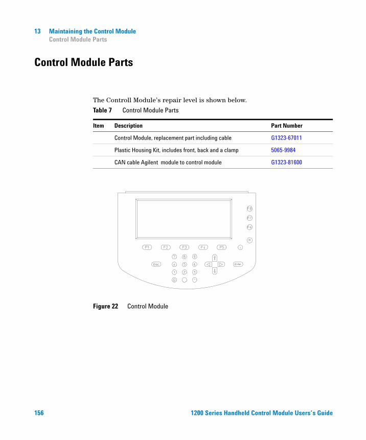
13 Maintaining the Control ModuleControl Module Parts
Control Module Parts
156
The Controll Module’s repair level is shown below.
Table 7 Control Module Parts
Item Description Part Number
Control Module, replacement part including cable G1323-67011
Plastic Housing Kit, includes front, back and a clamp 5065-9984
CAN cable Agilent module to control module G1323-81600
Figure 22 Control Module
1200 Series Handheld Control Module Users’s Guide

Agilent 1200 Series Handheld Control ModuleUser’s Guide
AAppendix
Safety Information 158
Radio Interference 161
Agilent Technologies on Internet 161
157Agilent Technologies
A AppendixSafety Information
Safety Information
158
The following general safety precautions must be observed during all phases of operation, service, and repair of this instrument. Failure to comply with these precautions or with specific warnings elsewhere in this manual violates safety standards of design, manufacture, and intended use of the instrument. Agilent Technologies assumes no liability for the customer’s failure to comply with these requirements.
General
This is a Safety Class I instrument (provided with terminal for protective earthing) and has been manufactured and tested according to international safety standards.
Operation
Before applying power, comply with the installation section. Additionally the following must be observed.
Do not remove instrument covers when operating. Before the instrument is switched on, all protective earth terminals, extension cords, auto-transformers, and devices connected to it must be connected to a protective earth via a ground socket. Any interruption of the protective earth grounding will cause a potential shock hazard that could result in serious personal injury. Whenever it is likely that the protection has been impaired, the instrument must be made inoperative and be secured against any intended operation.
Make sure that only fuses with the required rated current and of the specified type (normal blow, time delay, and so on) are used for replacement. The use of repaired fuses and the short-circuiting of fuseholders must be avoided.
1200 Series Handheld Control Module Users’s Guide
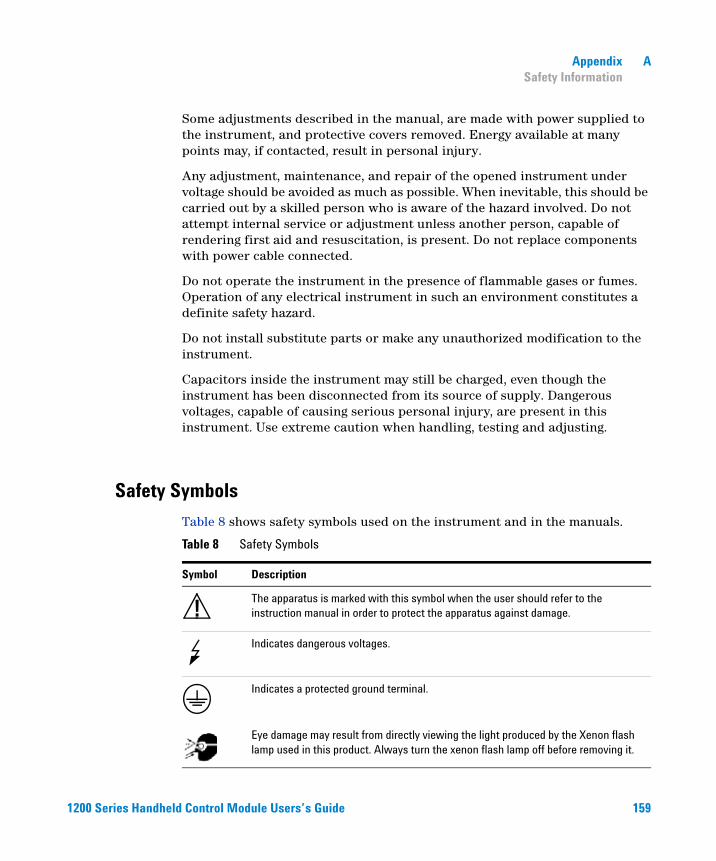
1200 Series Handhe
Appendix ASafety Information
Some adjustments described in the manual, are made with power supplied to the instrument, and protective covers removed. Energy available at many points may, if contacted, result in personal injury.
Any adjustment, maintenance, and repair of the opened instrument under voltage should be avoided as much as possible. When inevitable, this should be carried out by a skilled person who is aware of the hazard involved. Do not attempt internal service or adjustment unless another person, capable of rendering first aid and resuscitation, is present. Do not replace components with power cable connected.
Do not operate the instrument in the presence of flammable gases or fumes. Operation of any electrical instrument in such an environment constitutes a definite safety hazard.
Do not install substitute parts or make any unauthorized modification to the instrument.
Capacitors inside the instrument may still be charged, even though the instrument has been disconnected from its source of supply. Dangerous voltages, capable of causing serious personal injury, are present in this instrument. Use extreme caution when handling, testing and adjusting.
Safety Symbols
Table 8 shows safety symbols used on the instrument and in the manuals.
Table 8 Safety Symbols
Symbol Description
The apparatus is marked with this symbol when the user should refer to the instruction manual in order to protect the apparatus against damage.
Indicates dangerous voltages.
Indicates a protected ground terminal.
Eye damage may result from directly viewing the light produced by the Xenon flash lamp used in this product. Always turn the xenon flash lamp off before removing it.
!
ld Control Module Users’s Guide 159
A AppendixSafety Information
WARNING A warning alerts you to situations that could cause physical injury or damage to the equipment. Do not proceed beyond a warning until you have fully understood and met the indicated conditions.
CAUTION A caution alerts you to situations that could cause a possible loss of data. Do not proceed beyond a caution until you have fully understood and met the indicated conditions.
160 1200 Series Handheld Control Module Users’s Guide
Appendix ARadio Interference
Radio Interference
1200 Series Handhe
Never use cables other than the ones supplied by Agilent Technologies to ensure proper functionality and compliance with safety or EMC regulations.
Test and Measurement
If test and measurement equipment is operated with equipment unscreened cables and/or used for measurements on open set-ups, the user has to assure that under operating conditions the radio interference limits are still met within the premises.
Agilent Technologies on Internet
For the latest information on products and services visit our worldwide web site on the Internet at:
http://www.agilent.com
Select “Products”- “Chemical Analysis”
ld Control Module Users’s Guide 161

162
A AppendixAgilent Technologies on Internet
1200 Series Handheld Control Module Users’s Guide
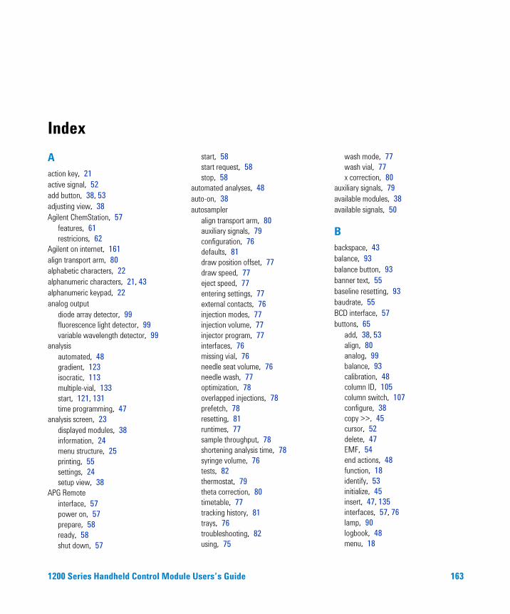
Index
Aaction key, 21active signal, 52add button, 38, 53adjusting view, 38Agilent ChemStation, 57
features, 61restricions, 62
Agilent on internet, 161align transport arm, 80alphabetic characters, 22alphanumeric characters, 21, 43alphanumeric keypad, 22analog output
diode array detector, 99fluorescence light detector, 99variable wavelength detector, 99
analysisautomated, 48gradient, 123isocratic, 113multiple-vial, 133start, 121, 131time programming, 47
analysis screen, 23displayed modules, 38information, 24menu structure, 25printing, 55settings, 24setup view, 38
APG Remoteinterface, 57power on, 57prepare, 58ready, 58shut down, 57
1200 Series Handheld Control Modu
start, 58start request, 58stop, 58
automated analyses, 48auto-on, 38autosampler
align transport arm, 80auxiliary signals, 79configuration, 76defaults, 81draw position offset, 77draw speed, 77eject speed, 77entering settings, 77external contacts, 76injection modes, 77injection volume, 77injector program, 77interfaces, 76missing vial, 76needle seat volume, 76needle wash, 77optimization, 78overlapped injections, 78prefetch, 78resetting, 81runtimes, 77sample throughput, 78shortening analysis time, 78syringe volume, 76tests, 82thermostat, 79theta correction, 80timetable, 77tracking history, 81trays, 76troubleshooting, 82using, 75
le Users’s Guide
wash mode, 77wash vial, 77x correction, 80
auxiliary signals, 79available modules, 38available signals, 50
Bbackspace, 43balance, 93balance button, 93banner text, 55baseline resetting, 93baudrate, 55BCD interface, 57buttons, 65
add, 38, 53align, 80analog, 99balance, 93calibration, 48column ID, 105column switch, 107configure, 38copy >>, 45cursor, 52delete, 47EMF, 54end actions, 48function, 18identify, 53initialize, 45insert, 47, 135interfaces, 57, 76lamp, 90logbook, 48menu, 18
163
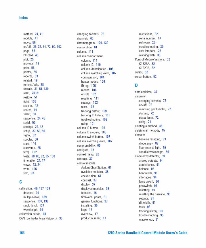
Index
method, 24, 41module, 41move, 50on/off, 25, 37, 64, 72, 90, 102page, 55PC card, 45plot, 25previous, 19print, 56printer, 55records, 53related, 19remove/add, 38rescale, 31, 51, 130reset, 70, 81restore, 51right, 105save as, 42search, 19select, 50sequence, 24, 48serial, 55settings, 24, 42setup, 37, 50, 56signal, 82spooler, 56start, 144start/stop, 25temp, 102tests, 68, 80, 82, 95, 108timetable, 24, 47views, 23, 24write, 105zero, 93
Ccalibration, 48, 137, 139
detector, 99multiple-level, 139sequence, 137, 139single-level, 137wavelength, 99
calibration button, 48CAN (Controller Area Network), 36
164
changing solvents, 73channels, 65chromatogram, 129, 130coexecution, 61column, 114column compartment
column, 114column ID, 110column identification, 105column switching valve, 107configuration, 104heater modes, 106ID tag, 105modes, 106on/off, 102resetting, 111settings, 103tests, 108tracking history, 109tracking ID history, 110troubleshooting, 108using, 101
column ID button, 105column ID module, 105column switch button, 107column switching valve, 107compressibility, 66configure, 38context menu, 20contrast, 37control module
Agilent ChemStation, 61available modules, 38coexecution, 61contrast, 37display, 37displayed modules, 38features, 16firmware update, 61general functions, 37installing, 36keys, 17overview, 17product number, 17
1200 Series Han
restrictions, 62serial number, 17software, 23troubleshooting, 39user interface, 23working with, 35
Control Module Versions, 32G1323A, 32G1323B, 32
cursor, 52cursor button, 52
Ddate and time, 37degasser
changing solvents, 73on/off, 72removing gas bubbles, 72starting, 72status lamp, 72using, 71
deleting a method, 45deleting all methods, 45detector
baseline resetting, 93diode array, 89fluorescence light, 89variable wavelength, 89
diode array detector, 89analog outputs, 94autobalance, 91balance, 93bandwidth, 91interfaces, 94lamp on/off, 90peakwidth, 91resetting, 97resetting the baseline, 93settings, 91slit width, 91tests, 95tracking history, 96troubleshooting, 95wavelength, 91
dheld Control Module Users’s Guide
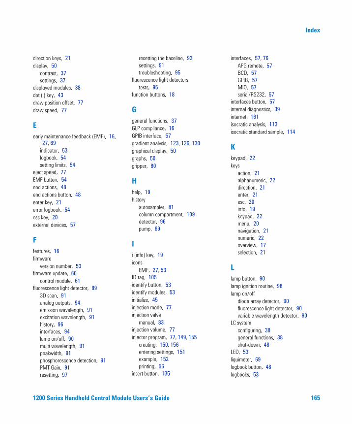
Index
direction keys, 21display, 50
contrast, 37settings, 37
displayed modules, 38dot (.) key, 43draw position offset, 77draw speed, 77
Eearly maintenance feedback (EMF), 16,
27, 69indicator, 53logbook, 54setting limits, 54
eject speed, 77EMF button, 54end actions, 48end actions button, 48enter key, 21error logbook, 54esc key, 20external devices, 57
Ffeatures, 16firmware
version number, 53firmware update, 60
control module, 61fluorescence light detector, 89
3D scan, 91analog outputs, 94emission wavelength, 91excitation wavelength, 91history, 96interfaces, 94lamp on/off, 90multi wavelength, 91peakwidth, 91phosphorescence detection, 91PMT-Gain, 91resetting, 97
1200 Series Handheld Control Modu
resetting the baseline, 93settings, 91troubleshooting, 95
fluorescence light detectorstests, 95
function buttons, 18
Ggeneral functions, 37GLP compliance, 16GPIB interface, 57gradient analysis, 123, 126, 130graphical display, 50graphs, 50gripper, 80
Hhelp, 19history
autosampler, 81column compartment, 109detector, 96pump, 69
Ii (info) key, 19icons
EMF, 27, 53ID tag, 105identify button, 53identify modules, 53initialize, 45injection mode, 77injection valve
manual, 83injection volume, 77injector program, 77, 149, 155
creating, 150, 156entering settings, 151example, 152printing, 56
insert button, 135
le Users’s Guide
interfaces, 57, 76APG remote, 57BCD, 57GPIB, 57MIO, 57serial/RS232, 57
interfaces button, 57internal diagnostics, 39internet, 161isocratic analysis, 113isocratic standard sample, 114
Kkeypad, 22keys
action, 21alphanumeric, 22direction, 21enter, 21esc, 20info, 19keypad, 22menu, 20navigation, 21numeric, 22overview, 17selection, 21
Llamp button, 90lamp ignition routine, 98lamp on/off
diode array detector, 90fluorescence light detector, 90variable wavelength detector, 90
LC systemconfiguring, 38general functions, 38shut-down, 48
LED, 53liquimeter, 69logbook button, 48logbooks, 53
165
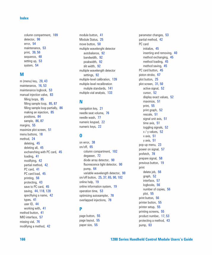
Index
column compartment, 109detector, 96error, 54maintenance, 53print, 39, 56sequence, 48setting up, 53system, 54
Mm (menu) key, 20, 43maintenance, 16, 53maintenance logbook, 53manual injection valve, 83
filling loops, 85filling sample loop, 85, 87filling sample loop partially, 86making an injection, 85positions, 84sample, 86, 87
margins, 55maximize plot screen, 51menu buttons, 18method, 24
deleting, 45deleting all, 45exchanching with PC card, 45loading, 41modifying, 42partial method, 42PC card, 41PC card load, 45printing, 56protecting, 43save to PC card, 45saving, 44, 118, 128specifiying a name, 42types, 41user ID, 44working with, 41
method button, 41MIO interface, 57missing vial, 76modifying a method, 42
166
module button, 41Module Status, 25move button, 50multiple wavelenght detector
autobalance, 92bandwidth, 92peakwidth, 92slit width, 92
multiple wavelength detectorsettings, 92
multiple-level calibration, 139multiple-level recalibration
muliple standards, 141multiple-vial analysis, 133
Nnavigation key, 21needle seat volume, 76needle wash, 77numeric keypad, 22numeric keys, 22
Oon error, 38on/off, 65
column compartment, 102degasser, 72diode array detector, 90fluorescence light detector, 90pump, 64variable wavelength detector, 90
on/off button, 25, 37, 65, 90, 102online help, 19online information system, 19operation time, 53optimizing autosampler, 78overlapped injections, 78
Ppage button, 55page layout, 55paper size, 55
1200 Series Han
parameter changes, 53partial method, 42PC card
initialize, 45inserting and removing, 40method exchanging, 45method loading, 45method saving, 45
PC card button, 45piston stroke, 67plot button, 25plot screen, 31, 50
active signal, 52cursor, 52display exact values, 52maximize, 51print, 55print graph, 52rescale, 51signal unit axis, 51time axis, 51toggling signals, 52x / y values, 52x axis, 51y axis, 51
pop-up menu, 23power on signal, 57prefetch, 78prepare signal, 58previous button, 19print
delete job, 56graph, 52interface, 57logbooks, 56number of copies, 56plot, 55
print button, 56printer button, 55printer setup, 55printing screens, 55product number, 17, 53protecting a method, 43pump, 63
dheld Control Module Users’s Guide
Index
adjusting compressibility, 66channels and composition, 65, 127on/off, 64piston, 67purging, 64resetting, 70resetting settings, 70settings, 64shut-down, 68stroke, 68tracking history, 69troubleshooting, 68using, 63valve, 64
purgeprocedure, 65pump, 64valve, 64
Rready signal, 58recalibration, 139
alter/multi, 48recalibration with same group of
standards, 139records nutton, 53refractive index detector
automatic recycling, 92cell temperature, 92peakwidth, 92polarity, 92settings, 92zero, 93
related button, 19remove button, 38rescale button, 31, 51, 130rescale plot screen, 51reset button, 70, 81resetting
autosampler, 81autosampler defaults, 81baseline, 93column compartment, 111detector, 97
1200 Series Handheld Control Modu
pump, 70pump settings, 70
restore button, 51right button, 105RS232 interface, 57running an analysis, 113running injector program, 149, 155
Ssample
amount, 86sample loop
completely filling, 85samples screen, 30
printing, 55save as button, 42saving a method, 44saving method, 118, 128screens
analysis, 23, 24, 25config, 55method, 56plot, 23, 31, 50program, 56records, 53samples, 23, 30sequence, 48status, 23, 29system, 23, 27timetable, 42views, 24
search button, 19select button, 50select signals, 50selection keys, 21sequence, 24, 48, 135, 137, 139
calibration, 48, 137, 139end actions, 48logbook, 48printing, 56recalibration, 48
sequence button, 48sequence modes, 144
le Users’s Guide
serial button, 55serial interface, 57serial number, 17, 53settings
detectors, 91diode array detector, 91fluorescence light detector, 91multiple wavelenght detector, 92refractive index detector, 92
settings button, 24, 42setup button, 37, 50, 56setup logbooks, 53setup view, 38shut down signal, 57shut-down pump, 68signal unit axis, 51signals button, 82single-level calibration, 137solvent composition, 65, 115solvents, 73spooler button, 56standard isocratic sample, 114standard mode, 144start button, 144start request signal, 58, 144, 145
external, 146start signal, 58, 144start/stop button, 25starting an analysis, 121, 131status screen, 29stop signal, 58stroke volume, 68syringe volume, 76system logbook, 54system screen
information, 27menu structure, 28
Ttag, 105tests
autosampler, 80, 82column compartment, 108
167
Index
detector, 95tests button, 68, 80, 82, 108thermostatted autosampler, 79
ambient temperature, 79auxiliary signals, 79display signals, 79heat sink, 79heat sink fan, 79parameters, 79plot, 79settings, 79signals, 79
theta correction, 80time and date, 37time axis, 51time programming, 47timeout, 38timetable, 24, 47
autosampler, 77copy / paste, 47printing, 56setting, 47
timetable button, 47toggling signals, 52transport arm aligning, 80trays, 76troubleshooting
autosampler, 82column compartment, 108control module, 39detectors, 95logbook, 39pump, 68
turning on/offcolumn compartment, 102
Uunits, 38updating firmware, 60user ID, 44
Vvalve
168
column compartment, 107filling sample loop, 85, 87filling sample loop partially, 86making an injection, 85manual, 83opening, 64positions, 84sample, 86, 87
variable wavelength detector, 89analog output, 94balance, 93interfaces, 94lamp ignition routine, 98lamp on/off, 90, 98resetting, 97resetting the baseline, 93settings, 91signal polarity, 91spectrum, 91tests, 95tracking history, 96troubleshooting, 95wavelength, 91wavelength calibration, 99
views, 24views button, 23
Wwash mode, 77wash vial, 77washing the needle, 77wavelength calibration, 99wear count, 69working with control module, 35working with methods, 41write button, 105
Xx / y values, 52x axis, 51x correction, 80
1200 Series Han
Yy axis, 51
Zzero button, 93
dheld Control Module Users’s Guide

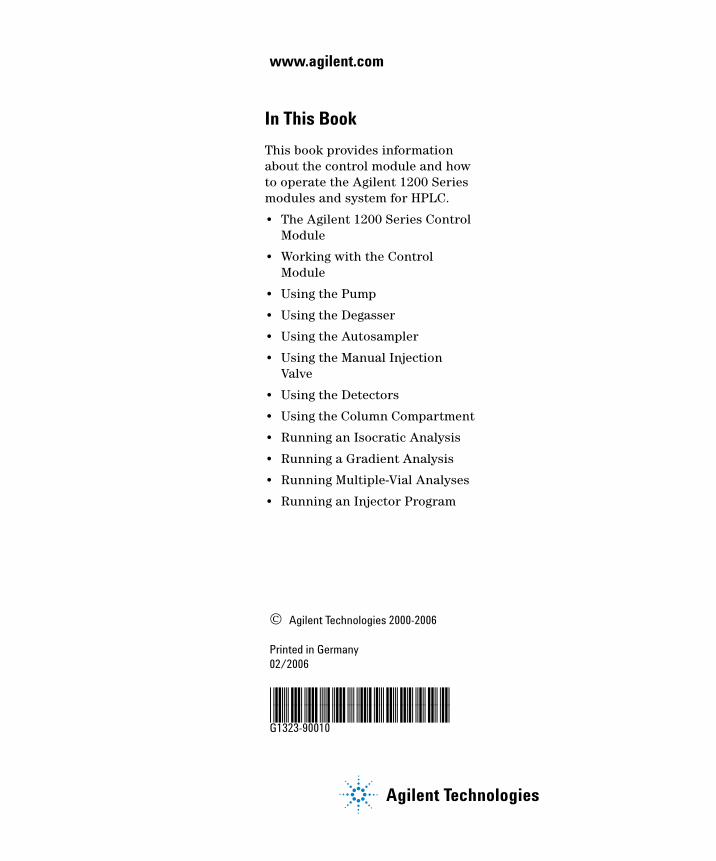
www.agilent.com
In This Book
This book provides information about the control module and how to operate the Agilent 1200 Series modules and system for HPLC.
• The Agilent 1200 Series Control Module
• Working with the Control Module
• Using the Pump
• Using the Degasser
• Using the Autosampler
• Using the Manual Injection Valve
• Using the Detectors
• Using the Column Compartment
• Running an Isocratic Analysis
• Running a Gradient Analysis
• Running Multiple-Vial Analyses
• Running an Injector Program
© Agilent Technologies 2000-2006
Printed in Germany 02/2006
*G1323-90010**G1323-90010*G1323-90010
Agilent Technologies