agilent 1200 series purification system · agilent 1200 series purification system user ... running...
TRANSCRIPT
A
Agilent 1200 Series Purification System
User Manual

Agilent 1200 Series Purification System User
Notices© Agilent Technologies, Inc. 2006
No part of this manual may be reproduced in any form or by any means (including elec-tronic storage and retrieval or translation into a foreign language) without prior agree-ment and written consent from Agilent Technologies, Inc. as governed by United States and international copyright laws.
Manual Part NumberG2262-90010
Edition02/06
Printed in Germany
Agilent Technologies Hewlett-Packard-Strasse 8 76377 Waldbronn
WarrantyThe material contained in this docu-ment is provided “as is,” and is sub-ject to being changed, without notice, in future editions. Further, to the max-imum extent permitted by applicable law, Agilent disclaims all warranties, either express or implied, with regard to this manual and any information contained herein, including but not limited to the implied warranties of merchantability and fitness for a par-ticular purpose. Agilent shall not be liable for errors or for incidental or consequential damages in connec-tion with the furnishing, use, or per-formance of this document or of any information contained herein. Should Agilent and the user have a separate written agreement with warranty terms covering the material in this document that conflict with these terms, the warranty terms in the sep-arate agreement shall control.
Technology Licenses The hardware and/or software described in this document are furnished under a license and may be used or copied only in accor-dance with the terms of such license.
Restricted Rights LegendIf software is for use in the performance of a U.S. Government prime contract or subcon-tract, Software is delivered and licensed as “Commercial computer software” as defined in DFAR 252.227-7014 (June 1995), or as a “commercial item” as defined in FAR 2.101(a) or as “Restricted computer soft-ware” as defined in FAR 52.227-19 (June 1987) or any equivalent agency regulation or contract clause. Use, duplication or disclo-sure of Software is subject to Agilent Tech-nologies’ standard commercial license terms, and non-DOD Departments and Agencies of the U.S. Government will receive no greater than Restricted Rights as
defined in FAR 52.227-19(c)(1-2) (June 1987). U.S. Government users will receive no greater than Limited Rights as defined in FAR 52.227-14 (June 1987) or DFAR 252.227-7015 (b)(2) (November 1995), as applicable in any technical data.
Safety Notices
CAUTION
A CAUTION notice denotes a haz-ard. It calls attention to an operat-ing procedure, practice, or the like that, if not correctly performed or adhered to, could result in damage to the product or loss of important data. Do not proceed beyond a CAUTION notice until the indicated conditions are fully understood and met.
WARNING
A WARNING notice denotes a hazard. It calls attention to an operating procedure, practice, or the like that, if not correctly per-formed or adhered to, could result in personal injury or death. Do not proceed beyond a WARNING notice until the indicated condi-tions are fully understood and met.
Agilent 1200 Series Purification System User Manual 3
In This Guide…This user’s guide describes the installation and operation of the Purification System.
1 Installing Your Agilent 1200 Series Purification System
This chapter contains site requirements and installation of the purification system.
2 Installing the Software
This chapter contains instructions and other information to help you install and start the Purification/Hi Throughput software on your ChemStation-PC.
3 Instrument Parameters
This chapter describes how to set up the CS instrument parameters that are necessary to run a study.
4 Menus and Views
This chapter describes the menu structure and toolbar buttons.
5 Study Setup
This chapter explains what a study is, and describes the process of setting up a study, including an explanation of all the necessary parameters.
6 Running Studies
This chapter describes the options for running and reprocessing studies.
7 Pooling
This chapter explains the concept of pooling, and describes how to set up a pooling run.
8 Data Review
This chapter describes the options available in the software for reviewing the study data.
4 Agilent 1200 Series Purification System User
9 Reports
This chapter describes the reporting options that are provided by the Purification/Hi Throughput software.
10 Directory Structure and File Naming
This chapter explains how the Purification/Hi Throughput files are organized, and how data files are named.
11 Checkout Procedures
This chapter describes the checkout procedures that are used to verify correct operation of hardware and software.
Contents
Agilent 1200 Series Purification System User Manual 5
Contents
1 Installing Your Agilent 1200 Series Purification System 13
Site Requirements 14
Power Considerations 14Power Cords 15Bench Space 15Weight Specifications 16Dimensions 17Environment and Physical Specifications 18Unpacking the Purification System 19Damaged Packaging 19Delivery Checklists 19
Optimizing the Stack Configuration and Plumbing of Your Purification System 20
Analytical Scale System Configurations 21Preparative Scale System Configurations 24
Installing the Purification System 27
Installing a Thermostatted Module in Your Purification System 31
Flow Connections to the Purification System 34
Flow Connections in an Analytical Scale System 36Flow Connections in a Preparative Scale System 38
2 Installing the Software 41
Before you start 42
Product Structure 43
Software Installation 44
Installation Process 44
Starting the Purification/Hi Throughput Software 47
Adding New Licenses or Uninstalling the SW 49
6 Agilent 1200 Series Purification System User Manual
Contents
3 Instrument Parameters 51
Prerequisites: Pump(s), Detector(s) (UV) and Column Compartment (if present) are Setup 52
Well-Plate Types 53
Preconfigured Well-Plate Types 53Configuration of Well-Plate Types 54
Autosamplers 57
Configuration 57Setup 61
Fraction Collector 67
Configuration 67Setup 70
Multiple Fraction Collectors 75
Configuring the Multiple Purpose Switching Valve 75Configuring Multiple Fraction Collectors 76Setting Up Multiple Fraction Collectors 76
Setting Up for Mass-based Fraction Collection 77
MSD Fraction Collection Dialog Box 80Fraction Collection Parameters Dialog Box 88
Delay Volume Calibration 93
Procedure for a Fraction Collector AS (G1364A #050 or G1364C) with an UV detector 94
Procedure for a Fraction Collector PS (G1364A or G1364B) with an UV detector 98
Procedure for a Fraction Collector AS with an MSD 102Procedure for a Fraction Collector PS with an MSD 107Making Your Own Calibration Method 112Delay Volume Calculations (UV Detector) 112Maximum flow rates to avoid missing peaks 114
Contents
Agilent 1200 Series Purification System User Manual 7
4 Menus and Views 119
Mode 120
Main Panel 121
Configuring the Tables 123
Menu Bar 125
File 125Run Control 126Edit 126View 128Options 129Window 129Help 130
Tool Bar 131
View Mode 133Select or Edit Mode 134
5 Study Setup 135
What is a Study? 136
Setting the Study Base Path 136Setting the Method Source Path 137
Setting Up a New Study 138
Creating a New Study 139Setting Up the Study Parameters 141Specifying the Report 144Completing the Study Setup 146
Adding Samples to the Study List 147
Sampler Panel 148Adding Samples 149Assigning Methods 150Modifying Samples 152
8 Agilent 1200 Series Purification System User Manual
Contents
Fraction Collector Panel 153The Study List 155Recovery Locations 156Assigning Recovery Locations 157
Using CSV Files 158
Setting up the CSV file 158Importing the CSV file 159Exporting to a CSV file 160Importing Expected Masses from a CSV File 161
Deleting Samples/ Injections from the Study List 163
Saving a Study 164
Deleting a Study 164
Opening a Study 165
Closing a Study 167
Modifying a Study 167
Setting Up a New Study Run 168
Setting Up a Partial Study 168
Adding Samples to a Partial Study 169Removing Samples from a Partial Study 169
6 Running Studies 171
Run Control 172
Starting a Study 172Stopping a Study 173Pausing a Study 173Aborting a Study 173Study Stop / Abort Criteria 173
Study Status 174
Online Tickmarks 175

Contents
Agilent 1200 Series Purification System User Manual 9
Reprocessing Studies 176
Resetting the Vessel Fill Volumes 177
7 Pooling 179
What is Pooling? 180
Pooling Properties 182
Setting Up a Study for Pooling 182
8 Data Review 183
Overview 184
Data View Panels 185
Study Parameters 185Sampler 186Fraction Collector 187Show Fraction Scheme 187Study Parameters 188Study List (Samples) 188Study List (Injections) 189Study List (Fraction Wells) 190Result Panel 191Configuring the Result Panel 192View Mode Tools 194Viewing data in Agilent ChemStation 196
9 Reports 199
Introduction 200
Producing Reports Interactively 201
Agilent ChemStation Reporting 202
Fraction Annotation 202Fraction Table 203Graphical Reporting 204
10 Agilent 1200 Series Purification System User Manual
Contents
Purification/Hi Throughput Reports 205
Study Run Summary 207Sample List 208Fraction List 209
10 Directory Structure and File Naming 211
Directory Structure 212
The Data Folder 213
Data File Naming 214
11 Checkout Procedures 217
Introduction 218
UV-triggered AS Fraction Collection Checkout 220
What you will Need 220Step 1: Calibrating the Delay Volume 221Step 2: Preparing the LC system 222Step 3: Creating a new study 224Step 4: Adding Sample(s) to the study 228Step 5: Starting the study 229Step 6: Reviewing the results 231Step 7: Reanalyzing fraction 3 233
UV-triggered PS Fraction Collection Checkout 235
What you will Need 235Step 1: Calibrating the Delay Volume 236Step 2: Preparing the LC system 236Step 3: Creating a new study 238Step 4: Adding Sample(s) to the study 241Step 5: Starting the study 242Step 6: Reviewing the results 243Step 7: Reanalyzing fraction 3 245
MSD-triggered AS Fraction Collection Checkout 248

Contents
Agilent 1200 Series Purification System User Manual 11
What you will need 248Step 1: Calibrating the Delay Time 249Step 2: Preparing the LC system 250Step 3: Running the Checkout Method 258Step 4: Review Results 258Step 5: Reanalyze Fraction #2 260
MSD-triggered PS Fraction Collection Checkout 261
What you will need 261Step 1: Calibrating the Delay Time 262Step 2: Preparing the LC system 263Step 3: Running the Checkout Method 272Step 4: Review Results 272Step 5: Reanalyze Fraction #2 274
Index 275
12 Agilent 1200 Series Purification System User Manual
Contents
13
Agilent 1200 Series Purification SystemUser Manual
Agilent Technologies
1Installing Your Agilent 1200 Series Purification System
Site Requirements 14
Optimizing the Stack Configuration and Plumbing of Your Purification System 20
Installing the Purification System 27
Installing a Thermostatted Module in Your Purification System 31
Flow Connections to the Purification System 34
This chapter contains site requirements and installation of the purification system
14 Agilent 1200 Series Purification System User Manual
1 Installing Your Agilent 1200 Series Purification System
Site Requirements
A suitable site environment is important to ensure optimum performance of your purification system.
Power Considerations
The purification system power supplies have wide-ranging capabilities (see Table 3 on page 18). Consequently there are no voltage selectors in the rear of the purification system modules. There are also no externally accessible fuses, because automatic electronic fuses are implemented in the power supplies.
WARNING To disconnect the purification system modules from line power, unplug the power cord of each module. The power supplies still use some power, even if the power switches ON the front panel of the modules are turned OFF.
WARNING Shock hazard or damage of your instrumentation can result if the devices are connected to a line voltage higher than specified.
Agilent 1200 Series Purification System User Manual 15
Installing Your Agilent 1200 Series Purification System 1
Power Cords
Your purification system modules are delivered with power cords which match the wall sockets of your particular country or region. The plug on the power cord which connects to the rear of the instrument is identical for all types of power cords.
Bench Space
The purification system dimensions and weight (see Table 1 on page 16 and Table 2 on page 17) allow the instruments to be placed on almost any laboratory bench. The instruments require an additional 2.5 cm (1.0 inch) of space on either side, approximately 8 cm (3.1 inches) at the rear for the circulation of air, and room for electrical connections.
If the thermostatted version of a sampler or fraction collector is used, an additional 25 cm (10 inches) of space on either side of the stack including the thermostat for the circulation of air and approximately 8 cm (3.1 inches) at the rear for electrical connections are required.
WARNING Never operate your instrumentation from a power outlet that has no ground connection. Never use power cords other than the power cords designed for your region.
WARNING Never use cables other than the ones supplied by Agilent Technologies to ensure proper functionality and compliance with safety or EMC regulations.
NOTE Ensure that each module of the purification system is installed in a horizontal position.
16 Agilent 1200 Series Purification System User Manual
1 Installing Your Agilent 1200 Series Purification System
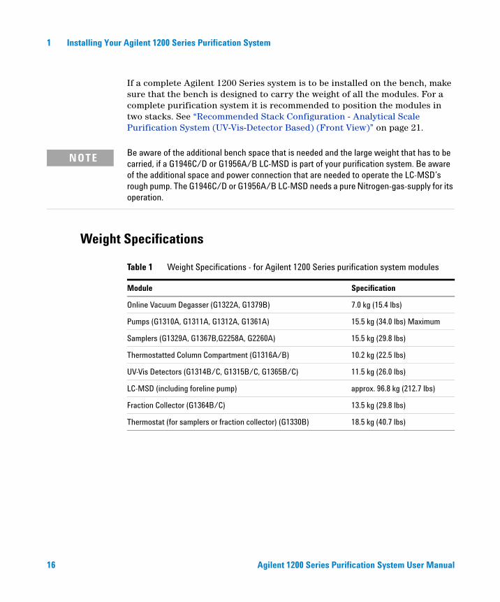
If a complete Agilent 1200 Series system is to be installed on the bench, make sure that the bench is designed to carry the weight of all the modules. For a complete purification system it is recommended to position the modules in two stacks. See “Recommended Stack Configuration - Analytical Scale Purification System (UV-Vis-Detector Based) (Front View)” on page 21.
Weight Specifications
NOTE Be aware of the additional bench space that is needed and the large weight that has to be carried, if a G1946C/D or G1956A/B LC-MSD is part of your purification system. Be aware of the additional space and power connection that are needed to operate the LC-MSD’s rough pump. The G1946C/D or G1956A/B LC-MSD needs a pure Nitrogen-gas-supply for its operation.
Table 1 Weight Specifications - for Agilent 1200 Series purification system modules
Module Specification
Online Vacuum Degasser (G1322A, G1379B) 7.0 kg (15.4 lbs)
Pumps (G1310A, G1311A, G1312A, G1361A) 15.5 kg (34.0 lbs) Maximum
Samplers (G1329A, G1367B,G2258A, G2260A) 15.5 kg (29.8 lbs)
Thermostatted Column Compartment (G1316A/B) 10.2 kg (22.5 lbs)
UV-Vis Detectors (G1314B/C, G1315B/C, G1365B/C) 11.5 kg (26.0 lbs)
LC-MSD (including foreline pump) approx. 96.8 kg (212.7 lbs)
Fraction Collector (G1364B/C) 13.5 kg (29.8 lbs)
Thermostat (for samplers or fraction collector) (G1330B) 18.5 kg (40.7 lbs)
Agilent 1200 Series Purification System User Manual 17
Installing Your Agilent 1200 Series Purification System 1
Dimensions
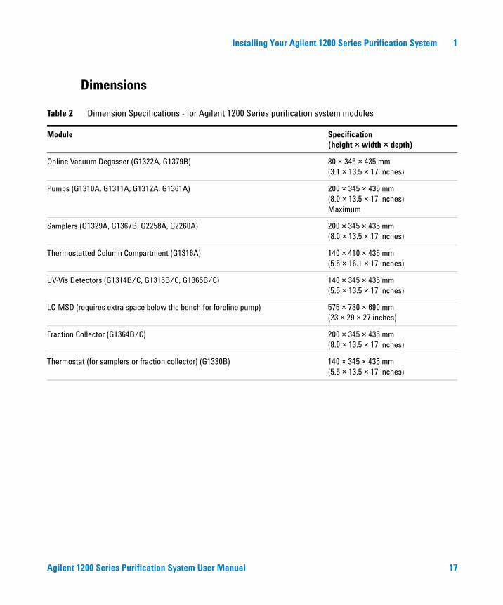
Table 2 Dimension Specifications - for Agilent 1200 Series purification system modules
Module Specification(height × width × depth)
Online Vacuum Degasser (G1322A, G1379B) 80 × 345 × 435 mm(3.1 × 13.5 × 17 inches)
Pumps (G1310A, G1311A, G1312A, G1361A) 200 × 345 × 435 mm(8.0 × 13.5 × 17 inches)Maximum
Samplers (G1329A, G1367B, G2258A, G2260A) 200 × 345 × 435 mm(8.0 × 13.5 × 17 inches)
Thermostatted Column Compartment (G1316A) 140 × 410 × 435 mm(5.5 × 16.1 × 17 inches)
UV-Vis Detectors (G1314B/C, G1315B/C, G1365B/C) 140 × 345 × 435 mm(5.5 × 13.5 × 17 inches)
LC-MSD (requires extra space below the bench for foreline pump) 575 × 730 × 690 mm (23 × 29 × 27 inches)
Fraction Collector (G1364B/C) 200 × 345 × 435 mm(8.0 × 13.5 × 17 inches)
Thermostat (for samplers or fraction collector) (G1330B) 140 × 345 × 435 mm(5.5 × 13.5 × 17 inches)
18 Agilent 1200 Series Purification System User Manual
1 Installing Your Agilent 1200 Series Purification System
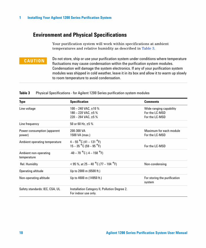
Environment and Physical Specifications
Your purification system will work within specifications at ambient temperatures and relative humidity as described in Table 3.
CAUTION Do not store, ship or use your purification system under conditions where temperature fluctuations may cause condensation within the purification system modules. Condensation will damage the system electronics. If any of your purification system modules was shipped in cold weather, leave it in its box and allow it to warm up slowly to room temperature to avoid condensation.
Table 3 Physical Specifications - for Agilent 1200 Series purification system modules
Type Specification Comments
Line voltage 100 – 240 VAC, ±10 % 180 – 220 VAC, ±5 % 220 – 264 VAC, ±5 %
Wide-ranging capabilityFor the LC-MSDFor the LC-MSD
Line frequency 50 or 60 Hz, ±5 %
Power consumption (apparent power)
200-300 VA1500 VA (max.)
Maximum for each moduleFor the LC-MSD
Ambient operating temperature 4 – 55 °C (41 – 131 °F)15 – 35 °C (59 – 95 °F) For the LC-MSD
Ambient non-operating temperature
-40 – 70 °C (-4 – 158 °F)
Rel. Humidity < 95 %, at 25 – 40 °C (77 – 104 °F) Non-condensing
Operating altitude Up to 2000 m (6500 ft.)
Non-operating altitude Up to 4600 m (14950 ft.) For storing the purification system
Safety standards: IEC, CSA, UL Installation Category II, Pollution Degree 2.For indoor use only.
Agilent 1200 Series Purification System User Manual 19
Installing Your Agilent 1200 Series Purification System 1
Unpacking the Purification System
If you need to ship any module of the purification system at a later date, always use the correct shipping boxes and protection foam parts.
Damaged Packaging
Upon receipt of your purification system, inspect the shipping containers for any signs of damage. If the containers or cushioning material are damaged, save them until the contents have been checked for completeness and the purification system has been mechanically and electrically checked. If the shipping container or cushioning material is damaged, notify the carrier and save the shipping material for the carrier‘s inspection.
Delivery Checklists
Ensure all parts and materials have been delivered with each of the purification system modules. For this, compare the shipment contents lists in the reference manual of each of the modules that are part of your purification system with the checklist included in each instrument box. Please report missing or damaged parts to your local Agilent Technologies sales and service office.
CAUTION If there are signs of damage to the purification system, please do not attempt to install the purification system.
20 Agilent 1200 Series Purification System User Manual
1 Installing Your Agilent 1200 Series Purification System
Optimizing the Stack Configuration and Plumbing of Your Purification System
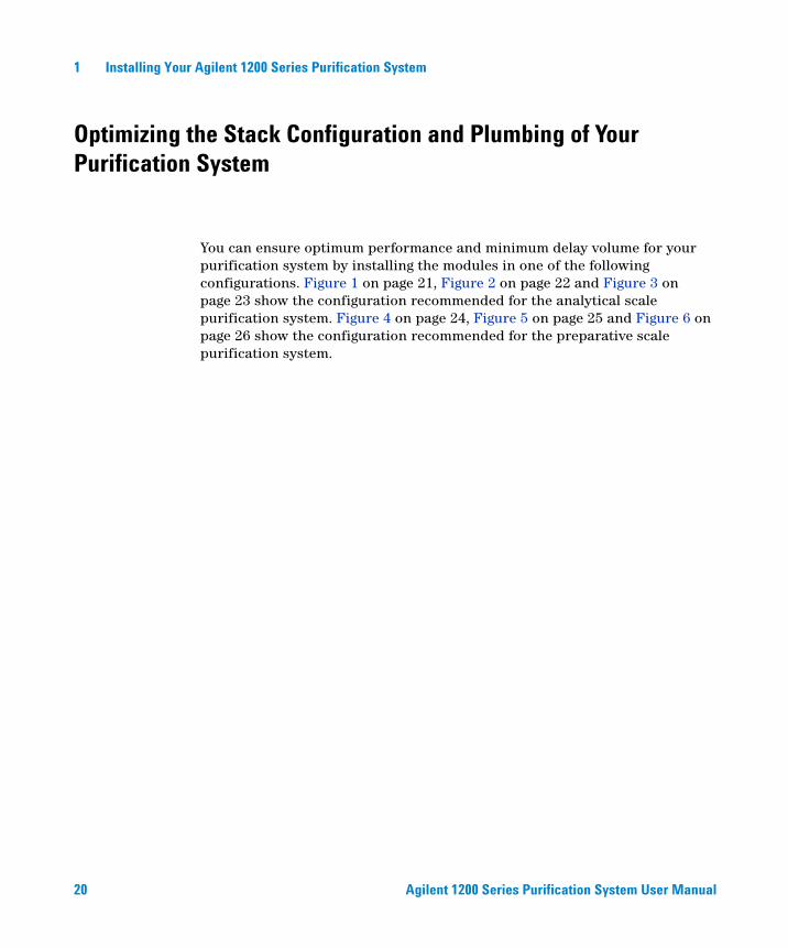
You can ensure optimum performance and minimum delay volume for your purification system by installing the modules in one of the following configurations. Figure 1 on page 21, Figure 2 on page 22 and Figure 3 on page 23 show the configuration recommended for the analytical scale purification system. Figure 4 on page 24, Figure 5 on page 25 and Figure 6 on page 26 show the configuration recommended for the preparative scale purification system.
Agilent 1200 Series Purification System User Manual 21
Installing Your Agilent 1200 Series Purification System 1
Analytical Scale System Configurations
Figure 1 Recommended Stack Configuration - Analytical Scale Purification System (UV-Vis-Detector Based) (Front View)
NOTE To identify the inter-module capillaries and tubing, as labelled in Figure 1, please refer to Table 4 on page 36!
NOTE The fraction collector should never be positioned on top of a module that generates heat. This could lead to an unwanted evaporation of fractions in the fraction collector (e.g. Agilent 1200 Series thermostatted column compartment G1316A/B or Agilent 1200 Series diode-array detectors G1315B/C.
I. Solvent bottles
III. Pump
IV. Sampling deviceVI. UV-Vis
VII. Fraction collectorV. Column
compartment
II. Degasser (optional, for all pumps except the Quat. Pump (G1311))
(1)
(2)
(3)
(4)(6)
(7)
(5)
waste
wastewaste waste
waste
(7)
22 Agilent 1200 Series Purification System User Manual
1 Installing Your Agilent 1200 Series Purification System
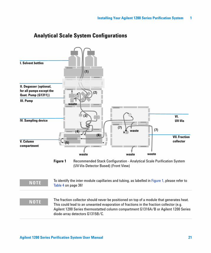
Figure 2 Recommended Stack Configuration - Analytical Scale Purification System (Including LC-MSD) (Front View)
NOTE To identify the inter-module capillaries and tubing, as labelled in Figure 2, please refer to Table 4 on page 36!
NOTE he fraction collector should never be positioned on top of a module that generates heat. This could lead to an unwanted evaporation of fractions in the fraction collector (e.g. Agilent 1200 Series thermostatted column compartment G1316A/B or Agilent 1200 Series diode-array detectors G1315B/C.
X. LC-MSD
VIII. Make-up Pump
IX. Flow Splitter
(1)
(2)
(3)
(4)
(7)
(5)
wastewaste waste
(8)
(1)
(3)
(9)
(7)
waste
waste

Agilent 1200 Series Purification System User Manual 23
Installing Your Agilent 1200 Series Purification System 1
NOTE For more details about the installation of any of the modules that are used only if the G1946C/D or G1956A/B LC-MSD is part of the system (G1310A Make-up pump, G1390A UIB, G1968-64102 MRA), please refer to the “G1968C Mass Based Fraction Collection Kit Installation Instructions” manual, available in the G1968C Mass-Based Fraction Collection kit.
Figure 3 Recommended Stack Configuration - Analytical Scale Purification System (UV-Vis-Detector Based) (Rear View)
GPIB or LANto LC ChemStation
CAN Bus cable
AC power
Analog signal to recorder
24 Agilent 1200 Series Purification System User Manual
1 Installing Your Agilent 1200 Series Purification System
Preparative Scale System Configurations
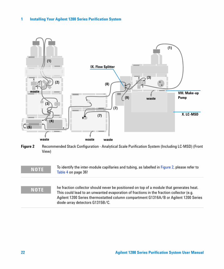
Figure 4 Recommended Stack Configuration - Preparative Scale Purification System (UV-Vis-Detector Based) (Front View)
NOTE To identify the inter-module capillaries and tubing, as labelled in Figure 4, please refer to Table 5 on page 38!
Prep. Pump A
Solvent bottles
UV-Vis Detector
Injection device
Fraction collector
Column organizer
Prep. Pump B
(1)
(2)
(3)
(4)
(5)
(6
waste wastewaste
(6waste
waste
Agilent 1200 Series Purification System User Manual 25
Installing Your Agilent 1200 Series Purification System 1
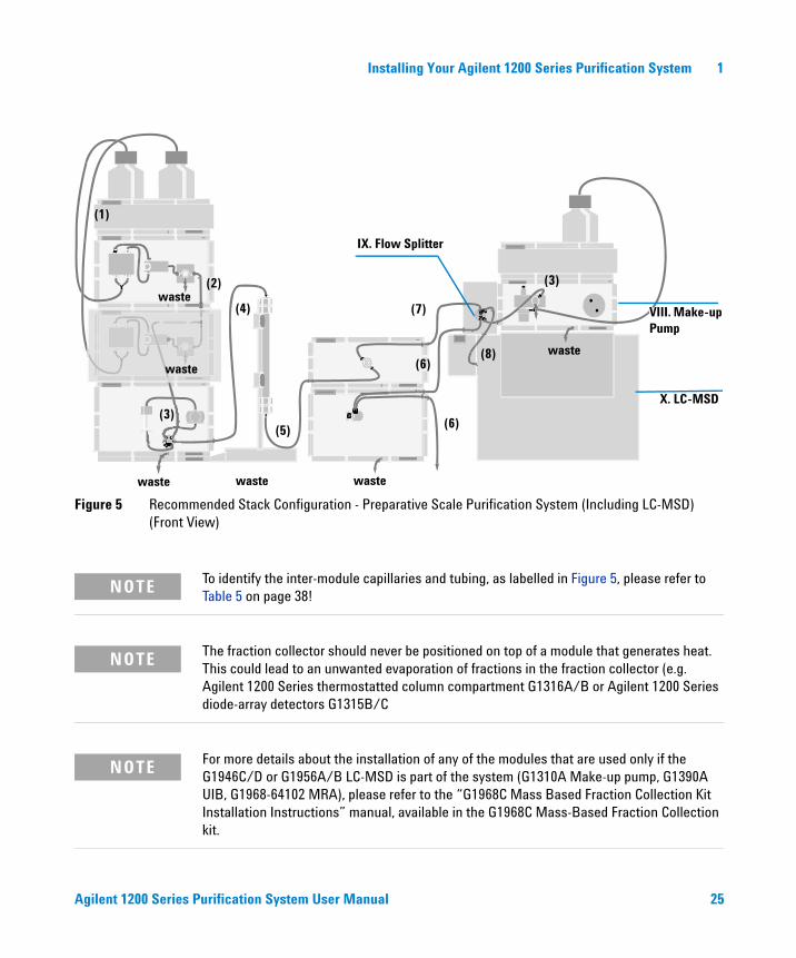
Figure 5 Recommended Stack Configuration - Preparative Scale Purification System (Including LC-MSD) (Front View)
NOTE To identify the inter-module capillaries and tubing, as labelled in Figure 5, please refer to Table 5 on page 38!
NOTE The fraction collector should never be positioned on top of a module that generates heat. This could lead to an unwanted evaporation of fractions in the fraction collector (e.g. Agilent 1200 Series thermostatted column compartment G1316A/B or Agilent 1200 Series diode-array detectors G1315B/C
NOTE For more details about the installation of any of the modules that are used only if the G1946C/D or G1956A/B LC-MSD is part of the system (G1310A Make-up pump, G1390A UIB, G1968-64102 MRA), please refer to the “G1968C Mass Based Fraction Collection Kit Installation Instructions” manual, available in the G1968C Mass-Based Fraction Collection kit.
IX. Flow Splitter
(1)
(2)
(3)
(4)
(5)
(6)waste
waste
waste
(7)
(6)
waste
waste
(3)
X. LC-MSD
VIII. Make-up Pump
waste
(8)
26 Agilent 1200 Series Purification System User Manual
1 Installing Your Agilent 1200 Series Purification System
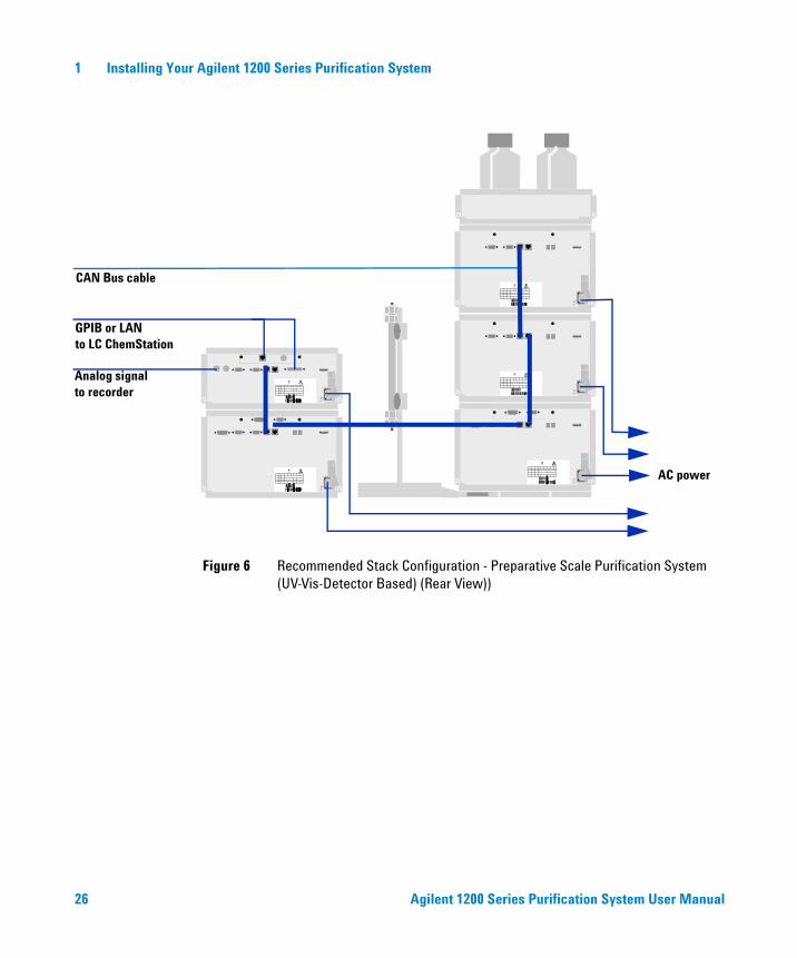
Figure 6 Recommended Stack Configuration - Preparative Scale Purification System (UV-Vis-Detector Based) (Rear View))
GPIB or LANto LC ChemStation
CAN Bus cable
AC power
Analog signal to recorder
Agilent 1200 Series Purification System User Manual 27
Installing Your Agilent 1200 Series Purification System 1
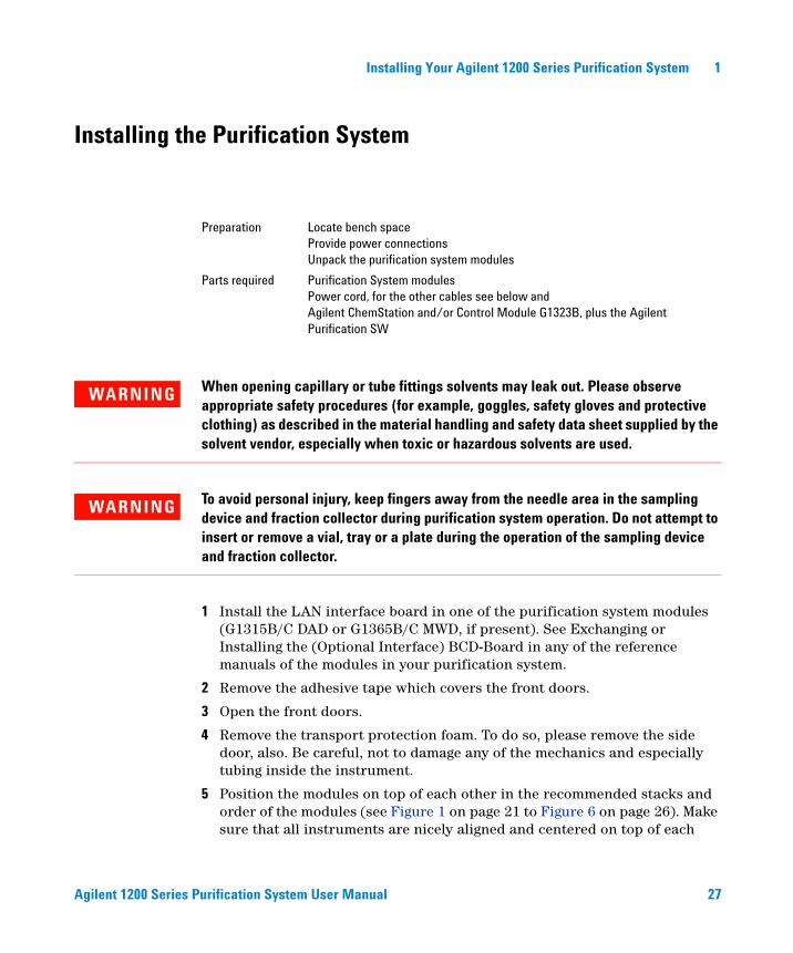
Installing the Purification System
1 Install the LAN interface board in one of the purification system modules (G1315B/C DAD or G1365B/C MWD, if present). See Exchanging or Installing the (Optional Interface) BCD-Board in any of the reference manuals of the modules in your purification system.
2 Remove the adhesive tape which covers the front doors.
3 Open the front doors.
4 Remove the transport protection foam. To do so, please remove the side door, also. Be careful, not to damage any of the mechanics and especially tubing inside the instrument.
5 Position the modules on top of each other in the recommended stacks and order of the modules (see Figure 1 on page 21 to Figure 6 on page 26). Make sure that all instruments are nicely aligned and centered on top of each
Preparation Locate bench spaceProvide power connectionsUnpack the purification system modules
Parts required Purification System modulesPower cord, for the other cables see below andAgilent ChemStation and/or Control Module G1323B, plus the Agilent Purification SW
WARNING When opening capillary or tube fittings solvents may leak out. Please observe appropriate safety procedures (for example, goggles, safety gloves and protective clothing) as described in the material handling and safety data sheet supplied by the solvent vendor, especially when toxic or hazardous solvents are used.
WARNING To avoid personal injury, keep fingers away from the needle area in the sampling device and fraction collector during purification system operation. Do not attempt to insert or remove a vial, tray or a plate during the operation of the sampling device and fraction collector.
28 Agilent 1200 Series Purification System User Manual
1 Installing Your Agilent 1200 Series Purification System
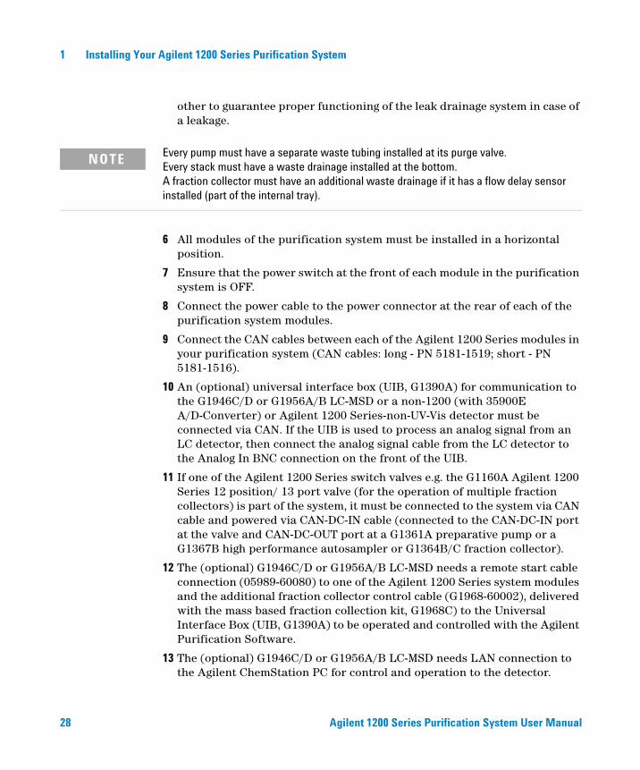
other to guarantee proper functioning of the leak drainage system in case of a leakage.
6 All modules of the purification system must be installed in a horizontal position.
7 Ensure that the power switch at the front of each module in the purification system is OFF.
8 Connect the power cable to the power connector at the rear of each of the purification system modules.
9 Connect the CAN cables between each of the Agilent 1200 Series modules in your purification system (CAN cables: long - PN 5181-1519; short - PN 5181-1516).
10 An (optional) universal interface box (UIB, G1390A) for communication to the G1946C/D or G1956A/B LC-MSD or a non-1200 (with 35900E A/D-Converter) or Agilent 1200 Series-non-UV-Vis detector must be connected via CAN. If the UIB is used to process an analog signal from an LC detector, then connect the analog signal cable from the LC detector to the Analog In BNC connection on the front of the UIB.
11 If one of the Agilent 1200 Series switch valves e.g. the G1160A Agilent 1200 Series 12 position/ 13 port valve (for the operation of multiple fraction collectors) is part of the system, it must be connected to the system via CAN cable and powered via CAN-DC-IN cable (connected to the CAN-DC-IN port at the valve and CAN-DC-OUT port at a G1361A preparative pump or a G1367B high performance autosampler or G1364B/C fraction collector).
12 The (optional) G1946C/D or G1956A/B LC-MSD needs a remote start cable connection (05989-60080) to one of the Agilent 1200 Series system modules and the additional fraction collector control cable (G1968-60002), delivered with the mass based fraction collection kit, G1968C) to the Universal Interface Box (UIB, G1390A) to be operated and controlled with the Agilent Purification Software.
13 The (optional) G1946C/D or G1956A/B LC-MSD needs LAN connection to the Agilent ChemStation PC for control and operation to the detector.
NOTE Every pump must have a separate waste tubing installed at its purge valve.Every stack must have a waste drainage installed at the bottom.A fraction collector must have an additional waste drainage if it has a flow delay sensor installed (part of the internal tray).
Agilent 1200 Series Purification System User Manual 29
Installing Your Agilent 1200 Series Purification System 1
14 If both the (optional) G1946C/D or G1956A/B LC-MSD and the rest of Agilent 1200 Series purification system are operated via LAN communication, an additional HUB has to be installed between the system, LC-MS detector and PC.
15 An (optional) Active Flow Splitter (MRA, PN G1968-64102) to use the LC-MSD in combination with a make-up-pump (typically G1310A) must be powered via 24V DC universal power supply (shipped with the MRA). The power output of the universal power supply must be connected to the MRA. The power cord for the operation of the universal power supply must be connected to the socket in the wall. The active splitter can be turned OFF and ON through either software control, manually or via external contacts (needs the G1351A External contacts board installed in the BCD board slot in one of the Agilent 1200 Series modules and the G1103-61611 general purpose cable).
16 Install the trays you have ordered for your sampler and fraction collector(s).
17 Turn ON power by pushing the button at the lower left hand side each of the purification system modules.
NOTE For more details about the installation of any of the modules that are used, only if the G1946C/D or G1956A/B LC-MSD is part of the system (G1310A Make-up pump, G1390A UIB, G1968-64102 MRA), please refer to the “G1968C Mass Based Fraction Collection Kit Installation Instructions” manual, available in the G1968C Mass-Based Fraction Collection kit.

30 Agilent 1200 Series Purification System User Manual
1 Installing Your Agilent 1200 Series Purification System
Figure 7 Cable Connections (Rear View of a G1367B or G1364B/C, as an Example)
NOTE A module of the purification system is turned ON when the line power switch is pressed and the green indicator lamp is illuminated. A module is turned OFF when the line power switch is protruding and the green light is OFF.
WARNING To disconnect the purification system modules from the line, unplug the power cord. Otherwise, the power supplies still uses some power, even if switches at the front panels are turned OFF.
THERMO REMOTE RS-232 CAN CAN CAN-DC-OUT CONFIG
RS-232
CAN-bus
Remote
CAN cable to previous module
Control of Thermostat
CAN-DC-Out
AC-Power
CAN cable to next module
Agilent 1200 Series Purification System User Manual 31
Installing Your Agilent 1200 Series Purification System 1
Installing a Thermostatted Module in Your Purification System
1 Place the thermostat on the bench.
2 Remove the front cover and route the condensation drain tube to a waste container.
3 Remove the adhesive tape which covers the side and front doors (if present).
4 Open the front door of each of the modules.
5 Remove the transport protection foam.
6 Install the corrugated waste tube in the plastic port at the front bottom center of the module (sampler or fraction collector) and route down into a waste container. Slide the waste tubing coming from the internal tray (if present) through the plastic port and the corrugated waste tube. Route the corrugated waste tubing into a waste container.
7 Place the module (sampler or fraction collector) on top of the thermostat. Make sure that the module (sampler or fraction collector) is correctly engaged in the thermostat locks.
Preparation Locate bench spaceProvide power connectionsUnpack the module (sampler or fraction collector) and the thermostat
Parts required Purification System modules and thermostatPower cords, for the other cables see below andChemStation and/or Control Module G1323B
WARNING Make sure the condensation drain tube runs down into a waste container without any (upwards) bends or curves. Free and unrestricted flow of the condensation into a waste container must be guaranteed. Make sure that the condensation drain tube is always above the liquid level in the container. If the tube is located in liquid the condensed water cannot flow out of the tube and the outlet is blocked. Any further condensation will then remain in the instrument. This may damage the instruments electronics.

32 Agilent 1200 Series Purification System User Manual
1 Installing Your Agilent 1200 Series Purification System
8 Remove the plastic cover from the tray base, place the air channel adapter (1) into the module (sampler or fraction collector) tray base. Make sure the adapter is fully pressed down. This ensures that the cold airstream from the thermostat is correctly guided to the tray area of the module (sampler or fraction collector). Place the plug channel (2) on top of the air channel adapter. Both devices must be installed correctly, to assure proper operation of the instrument.
9 Install the tray you have ordered for your module (sampler or fraction collector).
10 Ensure the power switch ON the front of the purification system is OFF and the power cables are disconnected.
11 Connect the cable (G1330-81600) between the module (sampler or fraction collector) and the thermostat, see “Connections at the Rear of the Thermostatted Module (Sampler or Fraction Collector)” on page 33.
12 Connect the power cables to the power connectors.
13 Connect the CAN cable to other Agilent 1200 Series modules.
Figure 8 Installation of G1330A/B Thermostat in the Purification System
1 2
WARNING Do not disconnect or reconnect the sampler / fraction collector to thermostat interconnection cable when the power cords are connected to either of the two modules. This will damage the electronics of the modules.

Agilent 1200 Series Purification System User Manual 33
Installing Your Agilent 1200 Series Purification System 1
14 Turn ON power by pushing the button at the lower left hand side of the purification system.
15 The module (sampler or fraction collector) is turned ON when the line power switch is pressed and the green indicator lamp is illuminated. The module (sampler or fraction collector) is turned 0FF when the line power switch is protruding and the green light is 0FF.
WARNING To disconnect the module (sampler or fraction collector) from the line, unplug the power cord. The power supply still uses some power, even if the power switch at the front panel is turned 0FF.
WARNING To avoid personal injury, keep fingers away from the needle area during purification system operation. Do not attempt to insert or remove a vial, tray or a plate during the operation of the sampling device and fraction collector.
Figure 9 Connections at the Rear of the Thermostatted Module (Sampler or Fraction Collector)
THERMO REMOTE RS-232 CAN CAN CAN-DC-OUT CONFIG
THERMO
Sampling device or Fraction Collector to Thermostat cable (G1330-81600)
CAN-bus AC Power
34 Agilent 1200 Series Purification System User Manual
1 Installing Your Agilent 1200 Series Purification System
Flow Connections to the Purification System
The following tables (and Figure 1 on page 21 to Figure 6 on page 26) give a rough overview of the plumbing and cabling of your purification system, only. For a more detailed layout of flow and electronic connections to the modules that are part of your purification system please refer to the installation sections in each of the reference manuals, delivered with every module.
Preparation Purification System is installed in the LC system
Parts required Parts from the accessory kits of each module, see accessory kit contents in the chapters 1 of the modules’ reference manuals, plus parts from the “G1968C Mass Based Fraction collection Kit” if the G1946C/D or G1956A/B LC-MSD is part of the system
WARNING When opening capillary or tube fittings, solvents may leak out. Please observe appropriate safety procedures (for example, goggles, safety gloves and protective clothing) as described in the material handling and safety data sheet supplied by the solvent vendor, especially when toxic or hazardous solvents are used.
WARNING This system should only be used with solvents that have an ignition temperature higher than 200oC!
NOTE If your stack configuration differs from the recommended ones, the capillaries delivered with the modules may not be long enough. In this case, it is possible to order additional capillaries of various lengths, separately. If multiple capillaries are connected to each other, it is recommended to use the zero dead volume union (PN 0100-0900 (AS) or 5022-2133 (PS)) for capillary to capillary connections.
Agilent 1200 Series Purification System User Manual 35
Installing Your Agilent 1200 Series Purification System 1
After connecting all inter-module tubings and capillaries, re-install the front covers of all of the modules.
NOTE Every pump must have a separate waste tubing installed at its purge valve. Every stack must have a waste drainage installed at its bottom.A fraction collector must have an additional waste drainage if it has a flow delay sensor installed (part of the internal tray).
NOTE If a G1330B ALS thermostat is part of the system it must always be installed underneath the module, that it is supposed to be thermostatted (any Agilent 1200 Series injector or fraction collector).
NOTE If a G1328A/B Manual Injector and/or a G1383A Column Organizer is installed, it should be installed between the two Agilent 1200 Series modules stacks.
NOTE If you want to operate multiple fraction collectors in parallel (up to three), this will be possible by installing the G1160A Agilent 1200 Series 12 position/13 port valve between the installed UV-detector and the fraction collectors. The length of all connecting tubings from the G1160A Agilent 1200 Series 12 position/13 port valve to the fraction collectors should be identical (same delay volume required to use the same delay volume in the configuration of each fraction collector. Otherwise it will be necessary to measure and configure the delay volume of each fraction collector individually.).
36 Agilent 1200 Series Purification System User Manual
1 Installing Your Agilent 1200 Series Purification System
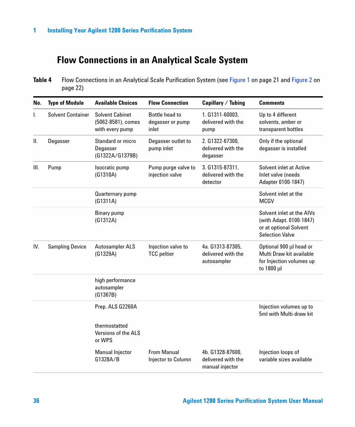
Flow Connections in an Analytical Scale System
Table 4 Flow Connections in an Analytical Scale Purification System (see Figure 1 on page 21 and Figure 2 on page 22)
No. Type of Module Available Choices Flow Connection Capillary / Tubing Comments
I. Solvent Container Solvent Cabinet(5062-8581), comes with every pump
Bottle head to degasser or pump inlet
1. G1311-60003, delivered with the pump
Up to 4 different solvents, amber or transparent bottles
II. Degasser Standard or micro Degasser (G1322A/G1379B)
Degasser outlet to pump inlet
2. G1322-67300, delivered with the degasser
Only if the optional degasser is installed
III. Pump Isocratic pump (G1310A)
Pump purge valve to injection valve
3. G1315-87311, delivered with the detector
Solvent inlet at Active Inlet valve (needs Adapter 0100-1847)
Quarternary pump (G1311A)
Solvent inlet at the MCGV
Binary pump (G1312A)
Solvent inlet at the AIVs (with Adapt. 0100-1847) or at optional Solvent Selection Valve
IV. Sampling Device Autosampler ALS (G1329A)
Injection valve to TCC peltier
4a. G1313-87305, delivered with the autosampler
Optional 900 μl head or Multi Draw kit available for Injection volumes up to 1800 μl
high performance autosampler (G1367B)
Prep. ALS G2260A Injection volumes up to 5ml with Multi-draw kit
thermostatted Versions of the ALS or WPS
Manual Injector G1328A/B
From Manual Injector to Column
4b. G1328-87600, delivered with the manual injector
Injection loops of variable sizes available
Agilent 1200 Series Purification System User Manual 37
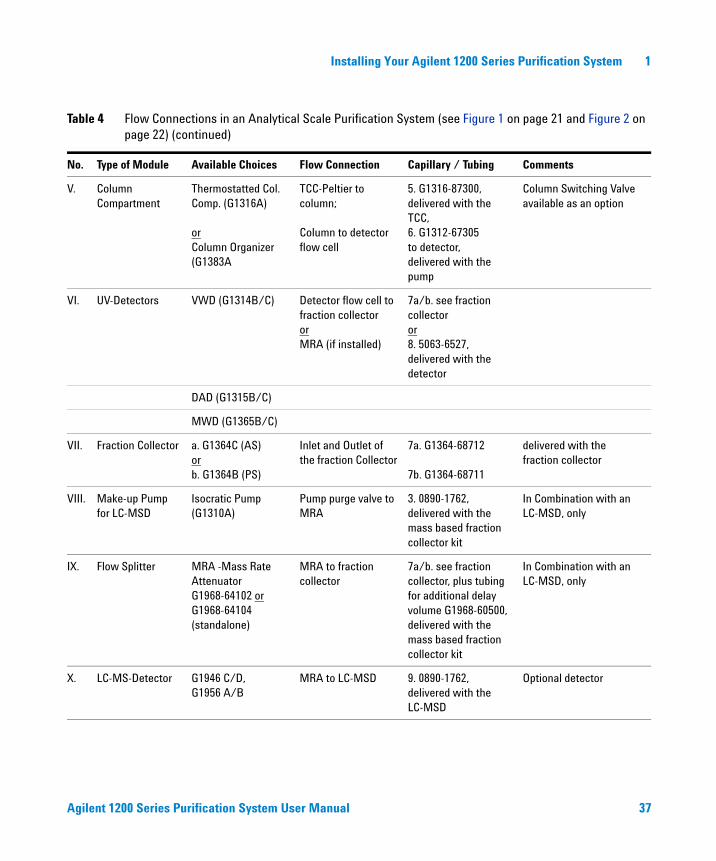
Installing Your Agilent 1200 Series Purification System 1
V. Column Compartment
Thermostatted Col. Comp. (G1316A)
orColumn Organizer (G1383A
TCC-Peltier to column;
Column to detector flow cell
5. G1316-87300, delivered with the TCC,6. G1312-67305 to detector, delivered with the pump
Column Switching Valve available as an option
VI. UV-Detectors VWD (G1314B/C) Detector flow cell to fraction collector or MRA (if installed)
7a/b. see fraction collector or8. 5063-6527, delivered with the detector
DAD (G1315B/C)
MWD (G1365B/C)
VII. Fraction Collector a. G1364C (AS) orb. G1364B (PS)
Inlet and Outlet of the fraction Collector
7a. G1364-68712
7b. G1364-68711
delivered with the fraction collector
VIII. Make-up Pump for LC-MSD
Isocratic Pump (G1310A)
Pump purge valve to MRA
3. 0890-1762, delivered with the mass based fraction collector kit
In Combination with an LC-MSD, only
IX. Flow Splitter MRA -Mass Rate Attenuator G1968-64102 or G1968-64104 (standalone)
MRA to fraction collector
7a/b. see fraction collector, plus tubing for additional delay volume G1968-60500, delivered with the mass based fraction collector kit
In Combination with an LC-MSD, only
X. LC-MS-Detector G1946 C/D,G1956 A/B
MRA to LC-MSD 9. 0890-1762, delivered with the LC-MSD
Optional detector
Table 4 Flow Connections in an Analytical Scale Purification System (see Figure 1 on page 21 and Figure 2 on page 22) (continued)
No. Type of Module Available Choices Flow Connection Capillary / Tubing Comments

38 Agilent 1200 Series Purification System User Manual
1 Installing Your Agilent 1200 Series Purification System
Flow Connections in a Preparative Scale System
Table 5 Flow Connections in an Preparative Scale Purification System (see Figure 4 on page 24 and Figure 5 on page 25)
No. Type of Module Available Choices Flow Connection Capillary / Tubing Comments
I. Solvent Container Solvent Cabinet(5062-8581), comes with every pump
Bottle head to pump inlet
1. G1361-60002, delivered with the pump
Up to 4 different solvents, amber or transparent bottles
II. Pump Prep. Pump G1361A (isocratic)
Pump A to Pump B 2. Interconnections, see prep. Pump Manual
Only for binary setup
III. Pump 2nd. Prep. Pump G1391A (for binary gradients)
Pump purge valve to injection valve
3. G1361-67302, delivered with the pump
IV. Sampling Device Prep. Autosampler ALS (G2260A)
Injection valve to Column
4a. G2260-87300, delivered with the ALS
With std. 900 μl head or optional Multi Draw kit available for Injection volumes up to 1800 μl
Dual-loop Autosampler G2258A
Injection valve to Column
4b. 5065-9930 delivered with the dual-loop autosampler
thermostatted Version of the Prep. ALS G2261A
Prep. Manual Injector 0101-1232
From Manual Injector to Column
4c. G2262-87300/1, delivered w. the valve
Injection loops of variable sizes available
V. Column Holder Column Organizer (G1383A)
Column to detector flow cell
5. G2260-87301, delivered with the ALS
needed for SST cell, only
VI. UV-Detectors DAD (G1315B/C) Detector flow cell to fraction collector or MRA (if installed)
6. see fraction collector or7. 5063-6527, delivered with the detector
MWD (G1365B/C)
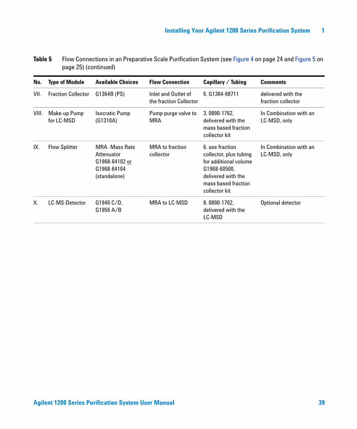
Agilent 1200 Series Purification System User Manual 39
Installing Your Agilent 1200 Series Purification System 1
VII. Fraction Collector G1364B (PS) Inlet and Outlet of the fraction Collector
6. G1364-68711 delivered with the fraction collector
VIII. Make-up Pump for LC-MSD
Isocratic Pump (G1310A)
Pump purge valve to MRA
3. 0890-1762, delivered with the mass based fraction collector kit
In Combination with an LC-MSD, only
IX. Flow Splitter MRA -Mass Rate Attenuator G1968-64102 or G1968-64104 (standalone)
MRA to fraction collector
6. see fraction collector, plus tubing for additional volume G1968-60500, delivered with the mass based fraction collector kit
In Combination with an LC-MSD, only
X. LC-MS-Detector G1946 C/D,G1956 A/B
MRA to LC-MSD 8. 0890-1762, delivered with the LC-MSD
Optional detector
Table 5 Flow Connections in an Preparative Scale Purification System (see Figure 4 on page 24 and Figure 5 on page 25) (continued)
No. Type of Module Available Choices Flow Connection Capillary / Tubing Comments
40 Agilent 1200 Series Purification System User Manual
1 Installing Your Agilent 1200 Series Purification System
41
Agilent 1200 Series Purification SystemUser Manual
Agilent Technologies
2Installing the Software
Before you start 42
Product Structure 43
Software Installation 44
Starting the Purification/Hi Throughput Software 47
Adding New Licenses or Uninstalling the SW 49
This chapter contains instructions and other information to help you install and start the Purification/Hi Throughput software on your Agilent ChemStation.

42 Agilent 1200 Series Purification System User Manual
2 Installing the Software
Before you start
Before you start the installation of the Purification/Hi Throughput software (Rev. B.01.01 or higher), you must complete the following tasks:
1 Install the hardware:
• Agilent 1200 Series Liquid Chromatograph
• Agilent 1200 Series LC/MSD (optional)
• Agilent 1200 Series Fraction Collector
• Universal Interface box (optional)
2 Make all necessary electrical connections.
3 Install the Agilent ChemStation Software revision B.01.01 or higher as described in the reference manual “Installing your Agilent ChemStation”. Verify that the software is operational.
NOTE Supported Operating Systems are ·Windows 2000 with Service Pack 3 OR Windows XP with Service Pack 1LC/CE Agilent ChemStation (G2170AA, G1601A)·Optional LC/MSD Agilent ChemStation (G2710AA)·Optional Agilent ChemStore (G1410A, G2181BA, G2186BA) B.03.02 or greaterThe system must meet all requirements of the above and any other installed/used software on the system.
Regional settings:·English (United States)·Number format (default for English (United States)) Decimal symbol ‘.’·Number format (default for English (United States)) Digit grouping symbol ‘,’
In addition to the requirements of the Agilent ChemStation, there must be one sampler configured (e.g. 1200 Series autosampler G1329A or high performance sampler G1367B). Any other module (like a fraction collector or a detector) is optional, but can be required for the availability of functionality.
Agilent 1200 Series Purification System User Manual 43
Installing the Software 2
4 Make sure that you are familiar with the Agilent 1200 Series LC, LC/MSD (if installed) and the Agilent ChemStation software.
Product Structure
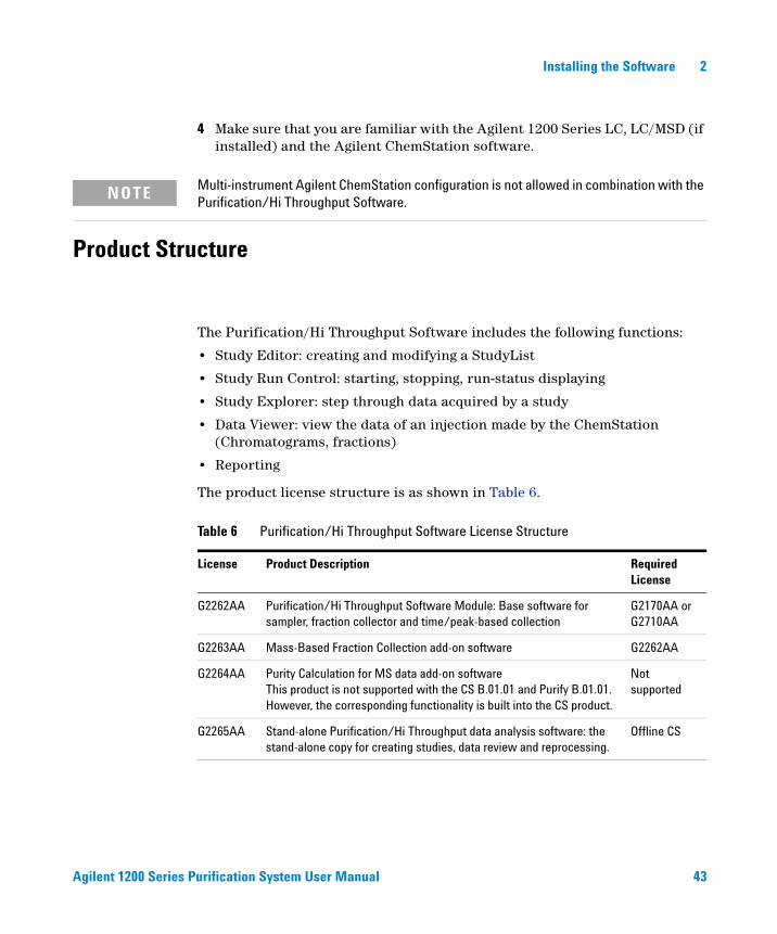
The Purification/Hi Throughput Software includes the following functions:
• Study Editor: creating and modifying a StudyList
• Study Run Control: starting, stopping, run-status displaying
• Study Explorer: step through data acquired by a study
• Data Viewer: view the data of an injection made by the ChemStation (Chromatograms, fractions)
• Reporting
The product license structure is as shown in Table 6.
NOTE Multi-instrument Agilent ChemStation configuration is not allowed in combination with the Purification/Hi Throughput Software.
Table 6 Purification/Hi Throughput Software License Structure
License Product Description Required License
G2262AA Purification/Hi Throughput Software Module: Base software for sampler, fraction collector and time/peak-based collection
G2170AA or G2710AA
G2263AA Mass-Based Fraction Collection add-on software G2262AA
G2264AA Purity Calculation for MS data add-on softwareThis product is not supported with the CS B.01.01 and Purify B.01.01. However, the corresponding functionality is built into the CS product.
Not supported
G2265AA Stand-alone Purification/Hi Throughput data analysis software: the stand-alone copy for creating studies, data review and reprocessing.
Offline CS

44 Agilent 1200 Series Purification System User Manual
2 Installing the Software
Software Installation
Installation Process
To install the Purification/Hi Throughput software,
1 Place the Purification/Hi Throughput CD-ROM in the CD-ROM drive.
2 From the Windows Start menu, run the file D:\Purify\Setup.exe, where D is the drive letter of your CD-ROM drive.
3 Follow the on-screen instructions and choose to install either the on-line or off-line software (Figure 10).
4 Select any additional components that you want to install (Figure 11).
Figure 10 Choosing the software to install
NOTE You must have the necessary licenses for all the options you select. You can only install either the Offline OR the Online version of the SW on one instrument.

Agilent 1200 Series Purification System User Manual 45
Installing the Software 2
You can add a G2263AA license / product for mass based fraction collection in combination with either G2262AA or G2265AA.
Figure 11 Selecting additional components
NOTEThe G2264AA Purity Calculation for MS data add-on software product is not supported with the CS B.01.01 and Purify B.01.01. However, the corresponding functionality is built into the CS product. There is no additional G2264AA license required for the B.01.01 Purification SW and CS B.01.01
46 Agilent 1200 Series Purification System User Manual
2 Installing the Software
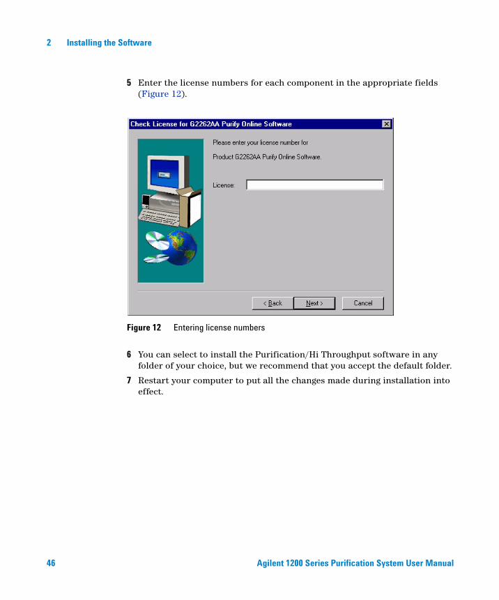
5 Enter the license numbers for each component in the appropriate fields (Figure 12).
6 You can select to install the Purification/Hi Throughput software in any folder of your choice, but we recommend that you accept the default folder.
7 Restart your computer to put all the changes made during installation into effect.
Figure 12 Entering license numbers
Agilent 1200 Series Purification System User Manual 47
Installing the Software 2
Starting the Purification/Hi Throughput Software
To start the Purification/Hi Throughput software,
1 If this is the first time you have started the Agilent ChemStation after installing the Purification/Hi Throughput software, switch the Agilent ChemStation to Full Menus.
View > Full Menu
This action inserts the Purify menu into the Agilent ChemStation menu bar. Once the Purify menu is present, you can access it from both full and short menus.
2 Switch to Method and Run Control View or Data Analysis View.
View > Method and Run Control
View > Data Analysis
3 Start the software from the Purify menu.
Purify > Start Software

48 Agilent 1200 Series Purification System User Manual
2 Installing the Software
The Purification/Hi Throughput software starts in a new window (see Figure 13).
Figure 13 New Purification/Hi Throughput Window
Agilent 1200 Series Purification System User Manual 49
Installing the Software 2
Adding New Licenses or Uninstalling the SW
If you want to add new licenses to your Purification/Hi Throughput software, for example Mass-Based Fraction Collection, you need to uninstall the existing Purification/Hi Throughput software and re-install the software including the new licenses.
To uninstall the software,
1 Open the Windows Start menu and choose Settings.
2 Select the Control Panel, and choose Add/Remove Programs.
3 Select the Purification Software from the list and click Add/Remove.
When you remove the software, the data is not affected; when you re-install the software, you can access the data as before.
NOTE To see which licenses are installed, display the About Purify panel from the Help menu.
50 Agilent 1200 Series Purification System User Manual
2 Installing the Software
51
Agilent 1200 Series Purification SystemUser Manual
Agilent Technologies
3Instrument Parameters
Well-Plate Types 53
Autosamplers 57
Fraction Collector 67
Multiple Fraction Collectors 75
Setting Up for Mass-based Fraction Collection 77
Delay Volume Calibration 93
This chapter describes how to set up the instrument parameters that are necessary to run a study.
52 Agilent 1200 Series Purification System User Manual
3 Instrument Parameters
Prerequisites: Pump(s), Detector(s) (UV) and Column Compartment (if present) are Setup
This chapter deals only with the setup and configuration of the modules, that require special handling related to purification topics. The setup of pumps, detectors and the thermostatted column compartment is not described. If you need help about how to setup any of these modules, please refer to your Agilents ChemStation’s Online Help.

Agilent 1200 Series Purification System User Manual 53
Instrument Parameters 3
Well-Plate Types
The high performance autosampler, the dual-loop autosampler, and fraction collector can accept well-plates that are either in a list of standard, preconfigured plates, or new plate configurations that were set up by you.
Preconfigured Well-Plate Types
The list of preconfigured well-plate types contains those well-plates that are supported as standard by the Agilent 1200 Series high performance autosampler and Agilent 1200 Series fraction collector. The table of well-plate types shows the dimensions of the wells and well-plate in accordance with Figure 14 on page 54.
To view the list of the preconfigured well-plate types, display the System Well-Plate Types dialog box.
1 Switch the Agilent ChemStation to Full Menus (if necessary).
View > Full Menu
2 Switch to Method and Run Control View (if necessary).
View > Method and Run Control
3 Open the System Well-Plate Types dialog box from the Instrument menu.
Instrument > Preconfigured Well-Plate Types
54 Agilent 1200 Series Purification System User Manual
3 Instrument Parameters
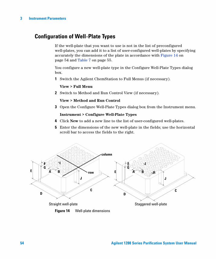
Configuration of Well-Plate Types
If the well-plate that you want to use is not in the list of preconfigured well-plates, you can add it to a list of user-configured well-plates by specifying accurately the dimensions of the plate in accordance with Figure 14 on page 54 and Table 7 on page 55.
You configure a new well-plate type in the Configure Well-Plate Types dialog box.
1 Switch the Agilent ChemStation to Full Menus (if necessary).
View > Full Menu
2 Switch to Method and Run Control View (if necessary).
View > Method and Run Control
3 Open the Configure Well-Plate Types dialog box from the Instrument menu.
Instrument > Configure Well-Plate Types
4 Click New to add a new line to the list of user-configured well-plates.
5 Enter the dimensions of the new well-plate in the fields; use the horizontal scroll bar to access the fields to the right.
Figure 14 Well-plate dimensions
GB
CD
E A
F I
J
column
row
Straight well-plate Staggered well-plate
GB
CD
E A
F I
J
H
Agilent 1200 Series Purification System User Manual 55
Instrument Parameters 3
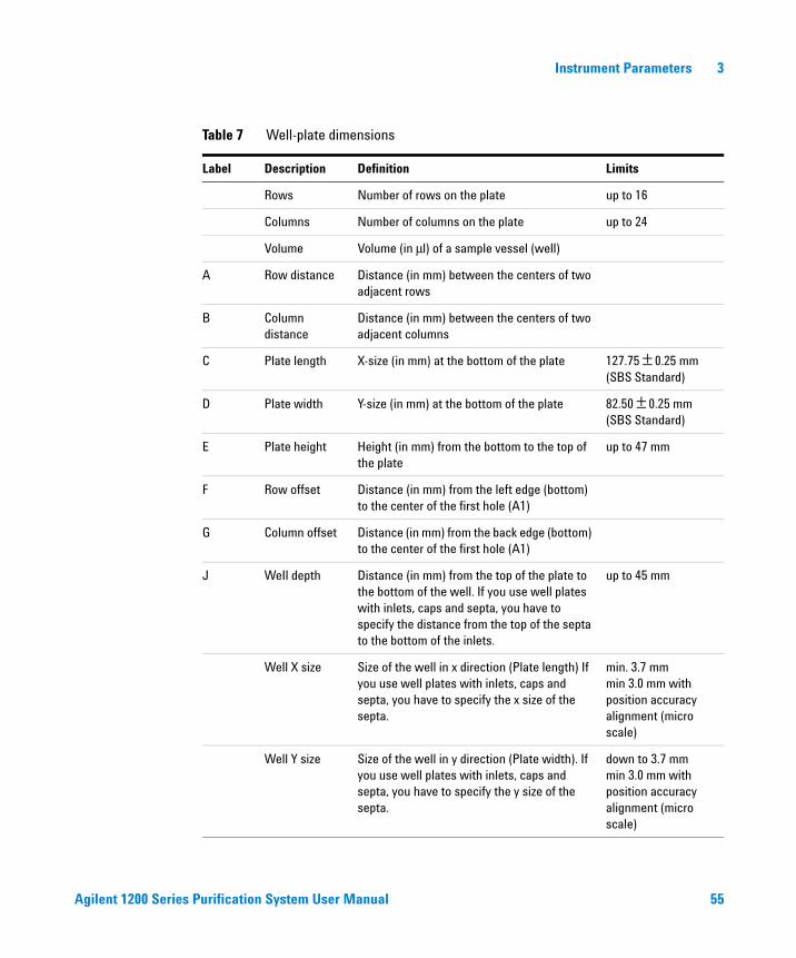
Table 7 Well-plate dimensions
Label Description Definition Limits
Rows Number of rows on the plate up to 16
Columns Number of columns on the plate up to 24
Volume Volume (in μl) of a sample vessel (well)
A Row distance Distance (in mm) between the centers of two adjacent rows
B Column distance
Distance (in mm) between the centers of two adjacent columns
C Plate length X-size (in mm) at the bottom of the plate 127.75 ± 0.25 mm(SBS Standard)
D Plate width Y-size (in mm) at the bottom of the plate 82.50 ± 0.25 mm(SBS Standard)
E Plate height Height (in mm) from the bottom to the top of the plate
up to 47 mm
F Row offset Distance (in mm) from the left edge (bottom) to the center of the first hole (A1)
G Column offset Distance (in mm) from the back edge (bottom) to the center of the first hole (A1)
J WeIl depth Distance (in mm) from the top of the plate to the bottom of the well. If you use well plates with inlets, caps and septa, you have to specify the distance from the top of the septa to the bottom of the inlets.
up to 45 mm
Well X size Size of the well in x direction (Plate length) If you use well plates with inlets, caps and septa, you have to specify the x size of the septa.
min. 3.7 mmmin 3.0 mm with position accuracy alignment (micro scale)
Well Y size Size of the well in y direction (Plate width). If you use well plates with inlets, caps and septa, you have to specify the y size of the septa.
down to 3.7 mmmin 3.0 mm with position accuracy alignment (micro scale)

56 Agilent 1200 Series Purification System User Manual
3 Instrument Parameters
6 Export the new configuration.
You can export the new configuration either to the preconfigured well-plate file (config.wpt) or to a separate configuration file. We recommend that you set up a separate configuration file for your non-standard well-plates (this file can then also be used to export configuration data to another Agilent ChemStation).
You can import your configuration file (or a file from a different ChemStation) to review or modify well-plate configurations. However, you do not need to import the file to add a new well-plate configuration. The import function allows you to import only files of the *.wpt-file format.
Bottom size For round wells, the relative of the top and bottom of the well
1.0: cylindrical well0.0: conical well
Square Click in the field to specify whether the well is rectangular or round
Yes: rectangularNo: round /oval
Is well plate Click in this field to specify if this is a well plate or not. Relevant for continuous flow operation.
Yes: well plateNo: Vial Tray or Eppendorf tray
Table 7 Well-plate dimensions (continued)
Label Description Definition Limits
Agilent 1200 Series Purification System User Manual 57
Instrument Parameters 3
Autosamplers
There are two aspects to the autosampler parameters:
Configuration is the process of characterizing the physical configuration of the autosampler, for example, by specifying the hardware (trays, syringe and seat capillary) that are installed.
Setup is the process of specifying the method parameters for injection conditions (for example, injection volume, injector program and syringe parameters).
Configuration
You configure the injector using the Injector Configuration dialog box.
1 Display the Injector context menu (right click on the Injector icon of the system diagram).
2 Select Configuration to open the Injector Configuration dialog box.
Alternatively, you can use the Agilent ChemStation menus:
1 Switch the Agilent ChemStation to Full Menus (if necessary)
View > Full Menu
2 Switch to Method and Run Control View (if necessary)
View > Method and Run Control
3 Open the Injector Configuration dialog box from the More Injector sub-menu of the Instrument menu.
Instrument > More Injector > Configuration
Configuring the Standard Autosampler
Supported standard autosamplers are:
• Autosampler, G1329A
58 Agilent 1200 Series Purification System User Manual
3 Instrument Parameters
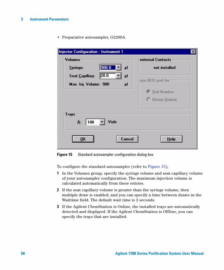
• Preparative autosampler, G2260A
To configure the standard autosampler (refer to Figure 15),
1 In the Volumes group, specify the syringe volume and seat capillary volume of your autosampler configuration. The maximum injection volume is calculated automatically from these entries.
2 If the seat capillary volume is greater than the syringe volume, then multiple draw is enabled, and you can specify a time between draws in the Waittime field. The default wait time is 2 seconds.
3 If the Agilent ChemStation is Online, the installed trays are automatically detected and displayed. If the Agilent ChemStation is Offline, you can specify the trays that are installed.
Figure 15 Standard autosampler configuration dialog box
Agilent 1200 Series Purification System User Manual 59
Instrument Parameters 3
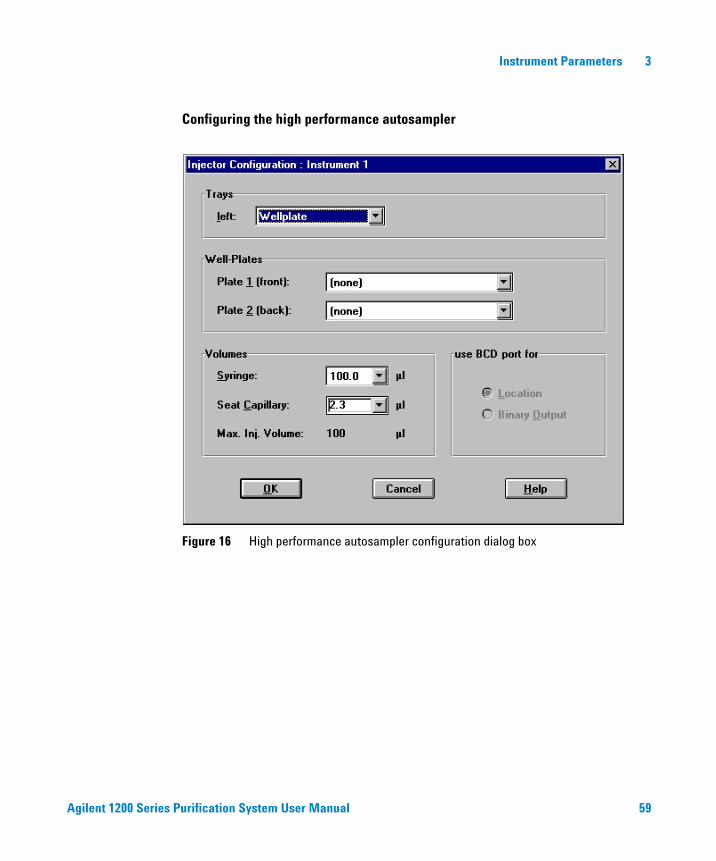
Configuring the high performance autosampler
Figure 16 High performance autosampler configuration dialog box

60 Agilent 1200 Series Purification System User Manual
3 Instrument Parameters
To configure the high performance autosampler (refer to Figure 16 on page 59),
1 If the Agilent ChemStation is on line, the installed trays are automatically detected and displayed. If the Agilent ChemStation is off line, you can specify the trays that are installed.
2 In the Well-plates group, specify the type of well-plates that are installed.
3 In the Volumes group, specify seat capillary volume of your high performance autosampler configuration. The maximum injection volume is calculated automatically from these entries.
Configuring the dual-loop autosampler
Figure 17 Dual-loop autosampler configuration dialog box
Agilent 1200 Series Purification System User Manual 61
Instrument Parameters 3
To configure the dual-loop autosampler (refer to Figure 17 on page 60),
1 If the Agilent ChemStation is on line, the installed trays are automatically detected and displayed. If the Agilent ChemStation is off line, you can specify the trays that are installed.
2 In the Well-plates group, specify the type of well-plates that are installed.
3 In the Volumes group, specify the volume of the upper and the lower loop. The maximum injection volume is calculated automatically from these entries.
4 In the Volumes group, specify the seat capillary volume for the upper and the lower loop of your dual-loop autosampler configuration. The maximum injection volume is calculated automatically from these entries.
Setup
You set up the injector using the Setup Injector dialog box.
1 Display the Injector context menu (right click on the Injector icon of the system diagram).
2 Select Set up Injector to open the Setup Injector dialog box.
Alternatively, you can use the Agilent ChemStation menus:
1 Switch to Method and Run Control View (if necessary)
View > Method and Run Control
2 Open the Set up Injector dialog box from the Instrument menu.
Instrument > Set up Injector
62 Agilent 1200 Series Purification System User Manual
3 Instrument Parameters
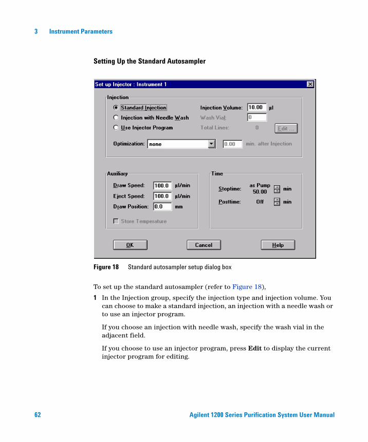
Setting Up the Standard Autosampler
To set up the standard autosampler (refer to Figure 18),
1 In the Injection group, specify the injection type and injection volume. You can choose to make a standard injection, an injection with a needle wash or to use an injector program.
If you choose an injection with needle wash, specify the wash vial in the adjacent field.
If you choose to use an injector program, press Edit to display the current injector program for editing.
Figure 18 Standard autosampler setup dialog box
Agilent 1200 Series Purification System User Manual 63
Instrument Parameters 3
2 In the Injection group, you can also choose an optimization program for fast throughput.
If you choose Overlap Injection Cycle, the next sample is drawn into the autosampler while the current sample is being run. You specify the time delay between sample injection and sample drawing.
If you choose Prefetch Sample Vial, the next sample vial is picked up while the current sample is being run. You specify the time delay between sample injection and vial collection.
3 In the Auxiliary group, specify the Draw and Eject speeds, and the Draw Position (offset to default position, “+” is higher / “-” is deeper) of the autosampler. For thermostatically controlled autosamplers, you can also select to store the temperature.
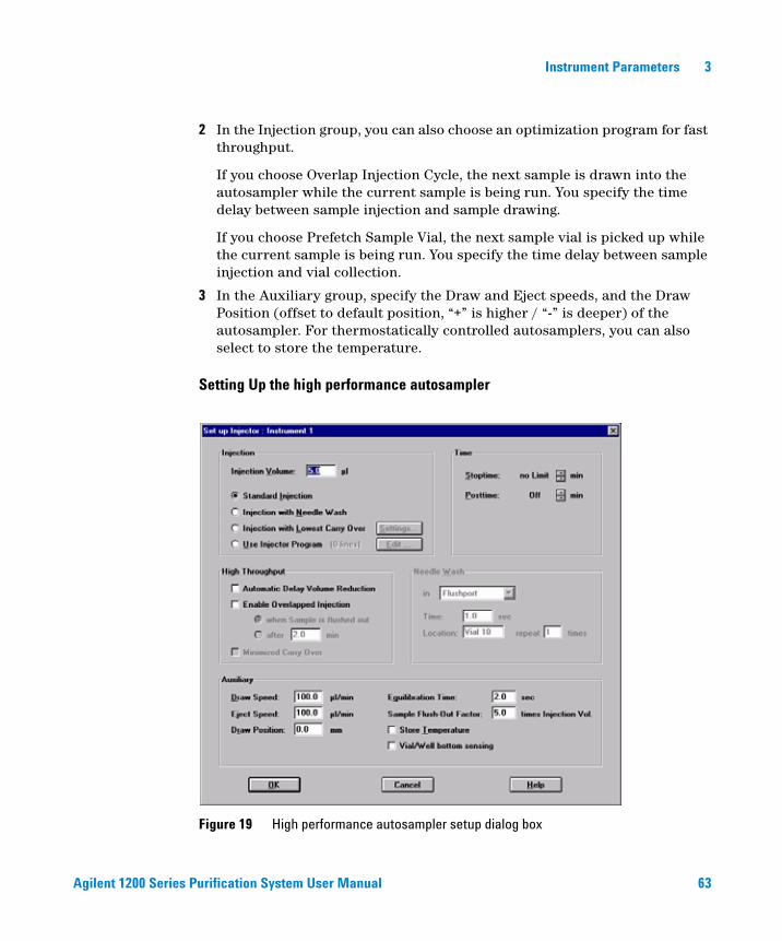
Setting Up the high performance autosampler
Figure 19 High performance autosampler setup dialog box
64 Agilent 1200 Series Purification System User Manual
3 Instrument Parameters
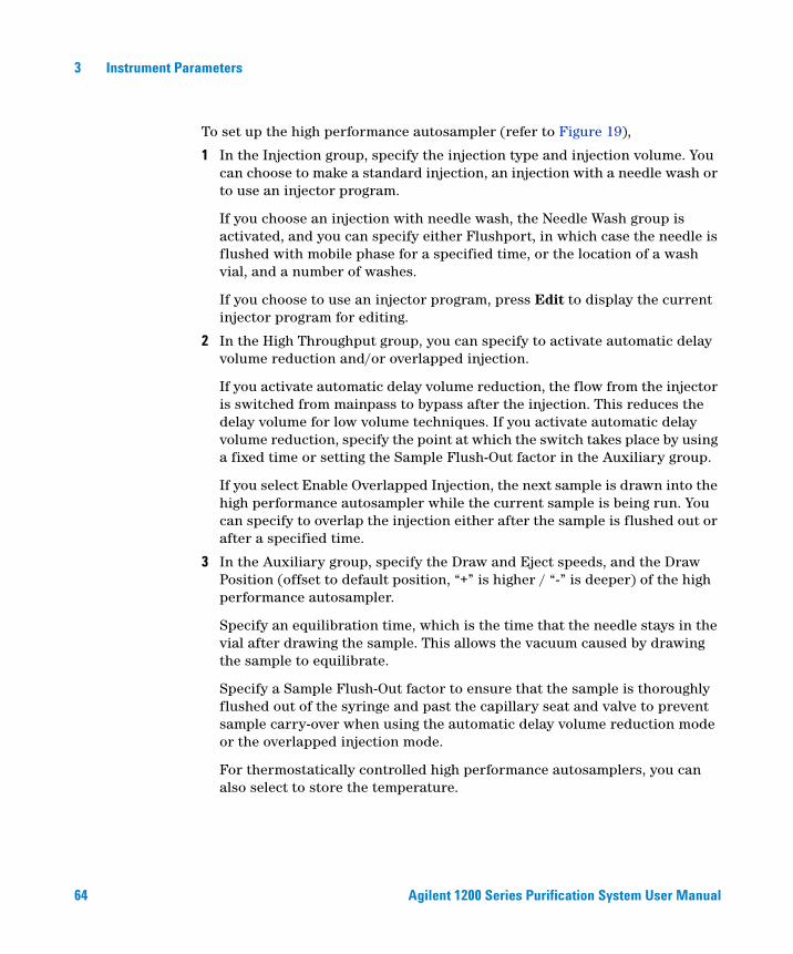
To set up the high performance autosampler (refer to Figure 19),
1 In the Injection group, specify the injection type and injection volume. You can choose to make a standard injection, an injection with a needle wash or to use an injector program.
If you choose an injection with needle wash, the Needle Wash group is activated, and you can specify either Flushport, in which case the needle is flushed with mobile phase for a specified time, or the location of a wash vial, and a number of washes.
If you choose to use an injector program, press Edit to display the current injector program for editing.
2 In the High Throughput group, you can specify to activate automatic delay volume reduction and/or overlapped injection.
If you activate automatic delay volume reduction, the flow from the injector is switched from mainpass to bypass after the injection. This reduces the delay volume for low volume techniques. If you activate automatic delay volume reduction, specify the point at which the switch takes place by using a fixed time or setting the Sample Flush-Out factor in the Auxiliary group.
If you select Enable Overlapped Injection, the next sample is drawn into the high performance autosampler while the current sample is being run. You can specify to overlap the injection either after the sample is flushed out or after a specified time.
3 In the Auxiliary group, specify the Draw and Eject speeds, and the Draw Position (offset to default position, “+” is higher / “-” is deeper) of the high performance autosampler.
Specify an equilibration time, which is the time that the needle stays in the vial after drawing the sample. This allows the vacuum caused by drawing the sample to equilibrate.
Specify a Sample Flush-Out factor to ensure that the sample is thoroughly flushed out of the syringe and past the capillary seat and valve to prevent sample carry-over when using the automatic delay volume reduction mode or the overlapped injection mode.
For thermostatically controlled high performance autosamplers, you can also select to store the temperature.
Agilent 1200 Series Purification System User Manual 65
Instrument Parameters 3
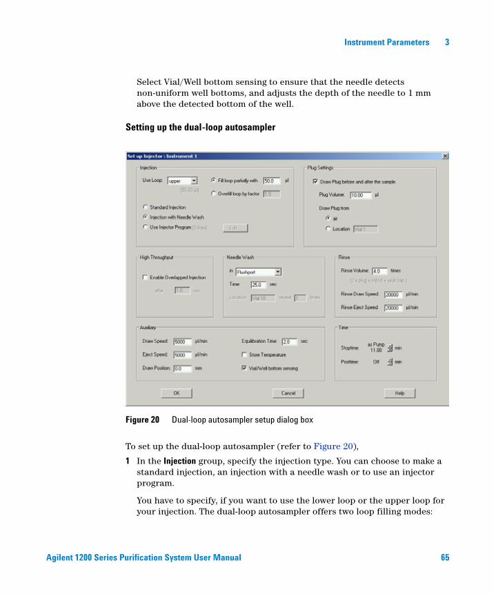
Select Vial/Well bottom sensing to ensure that the needle detects non-uniform well bottoms, and adjusts the depth of the needle to 1 mm above the detected bottom of the well.
Setting up the dual-loop autosampler
To set up the dual-loop autosampler (refer to Figure 20),
1 In the Injection group, specify the injection type. You can choose to make a standard injection, an injection with a needle wash or to use an injector program.
You have to specify, if you want to use the lower loop or the upper loop for your injection. The dual-loop autosampler offers two loop filling modes:
Figure 20 Dual-loop autosampler setup dialog box
66 Agilent 1200 Series Purification System User Manual
3 Instrument Parameters
• - fill loop partially with a specified injection volume. This mode is intended for preparative work and will provide a high sample recovery.
• - Overfill loop by a specified factor. This mode is intended for analytical work and will result in a high injector precision and reproducibility.
If you choose an injection with needle wash, the Needle Wash group is activated, and you can specify either Flushport, in which case the needle is flushed with mobile phase for a specified time, or the location of a wash vial, and a number of washes.
If you choose to use an injector program, press Edit to display the current injector program for editing.
2 In the Plug Settings group you can choose to draw an air or solvent plug before and after your sample. Specify the volume of your plugs and whether it should be an air plug or a solvent plug form a specified vial location.
3 In the High Throughput group, you can specify to use overlapped injections.
If you select Enable Overlapped Injection, the next sample is drawn into the dual-loop autosampler while the current sample is being run. You can specify to overlap the injection either after the sample is flushed out or after a specified time.
4 In the Rinse group you can specify how much solvent is used to rinse the syringe, the buffer loop and the seat capillary.
5 In the Auxiliary group, specify the Draw and Eject speeds, and the Draw Position (offset to default position, “+” is higher / “-” is deeper) of the dual-loop autosampler.
Specify an equilibration time, which is the time that the needle stays in the vial after drawing the sample. This allows the vacuum caused by drawing the sample to equilibrate.
Specify a Sample Flush-Out factor to ensure that the sample is thoroughly flushed out of the syringe and past the capillary seat and valve to prevent sample carry-over when using the overlapped injection mode.
For thermostatically controlled dual-loop autosamplers, you can also select to store the temperature.
Select Vial/Well bottom sensing to ensure that the needle detects non-uniform well bottoms, and adjusts the depth of the needle to 1 mm above the detected bottom of the well.

Agilent 1200 Series Purification System User Manual 67
Instrument Parameters 3
For more details see the User Manual of the Agilent 1200 Series dual-loop autosampler
Fraction Collector
There are two aspects to the fraction collector parameters:
Configuration is the process of characterizing the physical configuration of the fraction collector, for example, by specifying the trays that are installed, together with any reserved locations, the delay volume, and the collection conditions (for example, collection order, collection mode).
Setup is the process of specifying which detectors and which parameters will be used for triggering fraction collection.
Configuration
You configure the fraction collector using the Fraction Collector Configuration dialog box.
1 Display the Fraction Collector context menu (right click on the Fraction Collector icon of the system diagram).
2 Select Configuration to open the Fraction Collector Configuration dialog box.
Alternatively, you can use the Agilent ChemStation menus:
1 Switch the Agilent ChemStation to Full Menus (if necessary)
View > Full Menu
2 Switch to Method and Run Control View (if necessary)
View > Method and Run Control
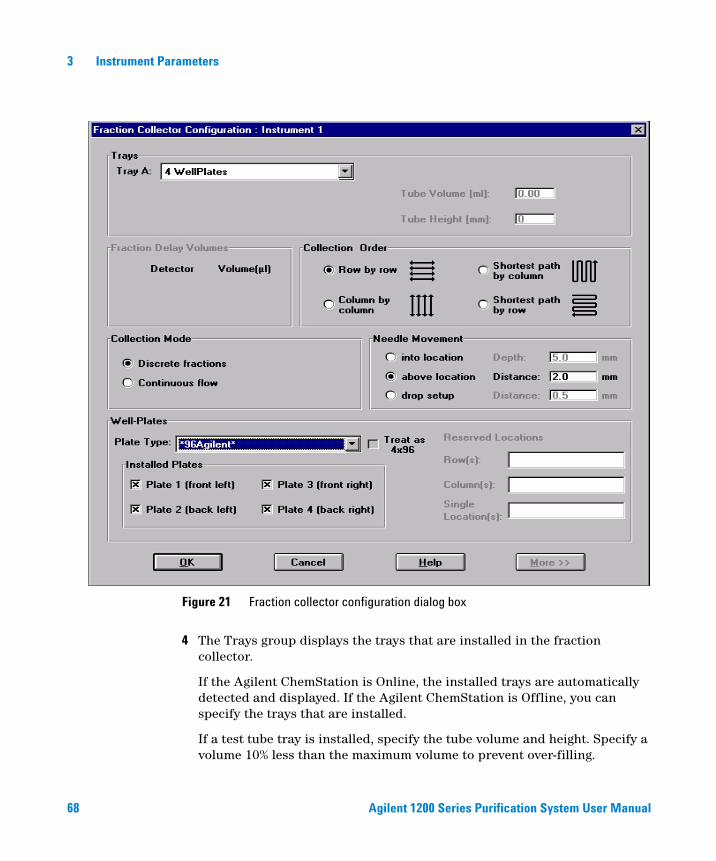
3 Open the Fraction Collector Configuration dialog box (Figure 21 on page 68) from the More Fraction Collector sub-menu of the Instrument menu.
Instrument > More Fraction Collector > Configuration
68 Agilent 1200 Series Purification System User Manual
3 Instrument Parameters
4 The Trays group displays the trays that are installed in the fraction collector.
If the Agilent ChemStation is Online, the installed trays are automatically detected and displayed. If the Agilent ChemStation is Offline, you can specify the trays that are installed.
If a test tube tray is installed, specify the tube volume and height. Specify a volume 10% less than the maximum volume to prevent over-filling.
Figure 21 Fraction collector configuration dialog box
Agilent 1200 Series Purification System User Manual 69
Instrument Parameters 3
5 In the Fraction Delay Volume group, specify a delay volume (in μl) for each of the detectors in use (see “Delay Volume Calibration” on page 93).
6 In the Collection Order group, select the collection pattern that you want to use.
7 In the Collection Mode group, select to collect discrete fractions or continuously (available for all supported vessels and trays).
If you select to collect discrete fractions, the diverter valve switches the flow to waste before the needle moves to the next collection position, so a small amount of sample is lost.
If you select continuous flow collection (available only with well-plates, not for capped vessels), the flow is diverted to waste only for long needle movements (for example, in the case of the 96-well plate, A12 to B1), so no sample is lost. However, there is a small risk of cross-contamination through splashing.
8 In the Needle Movement group, select where you want the needle to be positioned for fraction collection.
If you select to move the needle into location, the needle moves the specified depth into the container. This selection is required for capped vials, or if surface tension causes the solution to remain at the top of the well in 384 well-plates. Additional time is needed for the needle to move into location.
If you select to move the needle above location, the needle does not move down into the container, the needle moves across the tray with the specified distance to the specified vessel height. This selection is not suitable for capped vials.
The drop setup-mode is not available for analytical scale (AS) or preparative scale (PS) fraction collectors.
9 If well-plates are installed in the fraction collector, specify the type of well-plates and their positions in the Well-Plates group.
If 384-well plates are installed, you can also select to treat these in sections as four 96-well plates.
You can also specify reserved locations, which will not be used for fraction collection.
70 Agilent 1200 Series Purification System User Manual
3 Instrument Parameters
Setup
You set up the fraction collector using the Setup Fraction Collector dialog box.
1 Display the Fraction Collector context menu (right click on the Fraction Collector icon of the system diagram).
2 Select Set up Fraction Collector to open the Setup Fraction Collector dialog box.
Alternatively, you can use the Agilent ChemStation menus:
1 Switch to Method and Run Control View (if necessary).
View > Method and Run Control
2 Open the Set up Fraction Collector dialog box from the Instrument menu.
Instrument > Set up Fraction Collector
NOTE The specified reserved locations apply to all installed plates.
Agilent 1200 Series Purification System User Manual 71
Instrument Parameters 3
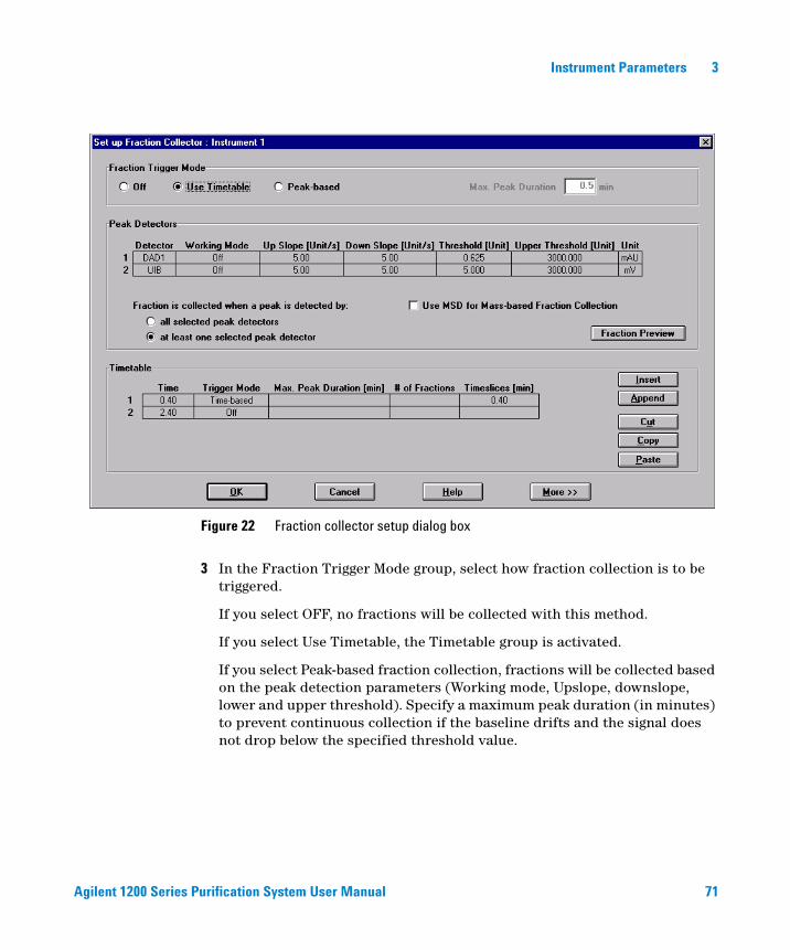
3 In the Fraction Trigger Mode group, select how fraction collection is to be triggered.
If you select OFF, no fractions will be collected with this method.
If you select Use Timetable, the Timetable group is activated.
If you select Peak-based fraction collection, fractions will be collected based on the peak detection parameters (Working mode, Upslope, downslope, lower and upper threshold). Specify a maximum peak duration (in minutes) to prevent continuous collection if the baseline drifts and the signal does not drop below the specified threshold value.
Figure 22 Fraction collector setup dialog box
72 Agilent 1200 Series Purification System User Manual
3 Instrument Parameters
• Peak Detector ParametersWith Working Mode, you determine, whether a selected peak detector is not used for fraction triggering (OFF) or whether fractions are collected based on the Slope parameters, only or Threshold parameters, only. It is also possible to collect on Threshold and Slope at the same time. A peak start is triggered then, if both the Upslope value AND the Threshold are exceeded. The peak end will be triggered, when the signal falls below the Threshold OR the Downslope value is exceeded OR if you exceed the max. peak Duration as entered in the Fraction Trigger Mode. Above the Upper Threshold a peak will always be collected, independent of the current slope (for use with saturated peaks).
4 In the Peak Detectors group, specify which of the configured detectors will be used for peak detection, and specify the peak detection parameters for each selected detector.
You also select whether fraction collection is triggered when any detector detects a peak, or only when all detectors detect a peak.
5 The Timetable allows you to switch fraction collection ON and OFF during the run, and to change the trigger type and parameters. In addition to the peak-based trigger, the Timetable also allows you to set up time-based fraction collection, based on either a number of fractions or a specified fraction collection time.
Agilent 1200 Series Purification System User Manual 73
Instrument Parameters 3
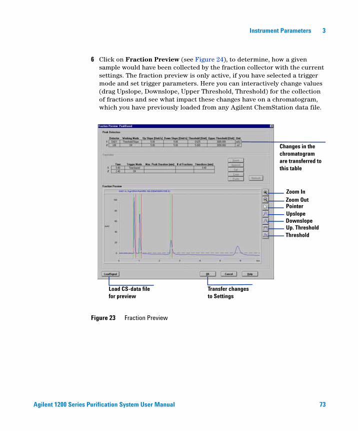
6 Click on Fraction Preview (see Figure 24), to determine, how a given sample would have been collected by the fraction collector with the current settings. The fraction preview is only active, if you have selected a trigger mode and set trigger parameters. Here you can interactively change values (drag Upslope, Downslope, Upper Threshold, Threshold) for the collection of fractions and see what impact these changes have on a chromatogram, which you have previously loaded from any Agilent ChemStation data file.
Figure 23 Fraction Preview
Changes in the chromatogram are transferred to this table
Zoom InZoom OutPointerUpslope
Up. ThresholdThreshold
Downslope
Transfer changes to Settings
Load CS-data file for preview
74 Agilent 1200 Series Purification System User Manual
3 Instrument Parameters
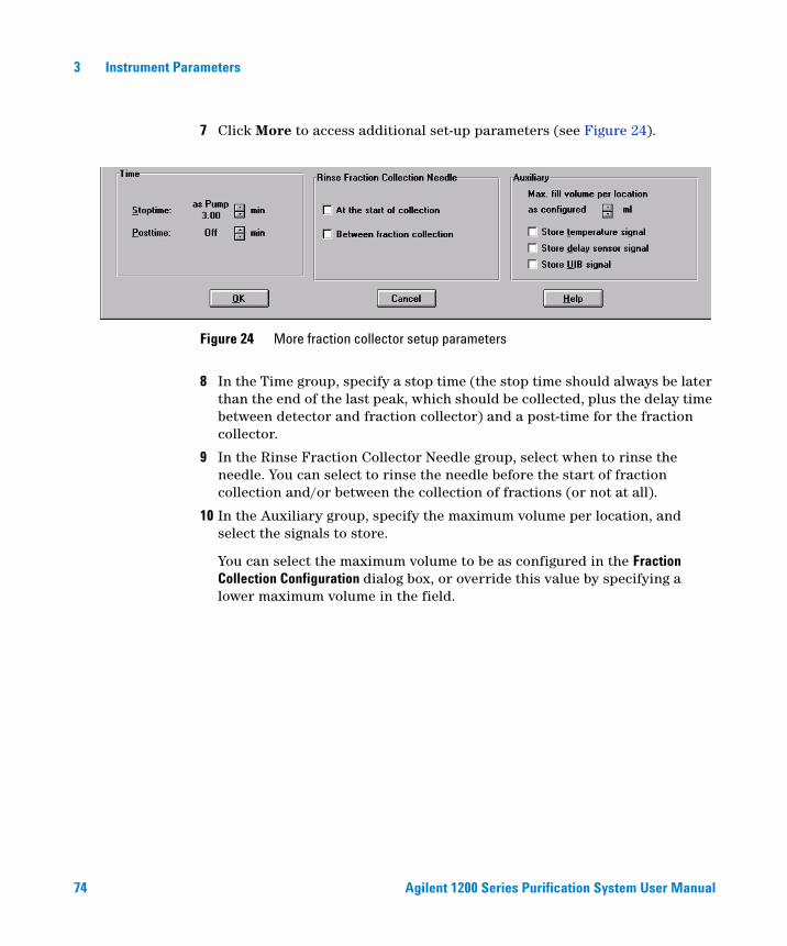
7 Click More to access additional set-up parameters (see Figure 24).
8 In the Time group, specify a stop time (the stop time should always be later than the end of the last peak, which should be collected, plus the delay time between detector and fraction collector) and a post-time for the fraction collector.
9 In the Rinse Fraction Collector Needle group, select when to rinse the needle. You can select to rinse the needle before the start of fraction collection and/or between the collection of fractions (or not at all).
10 In the Auxiliary group, specify the maximum volume per location, and select the signals to store.
You can select the maximum volume to be as configured in the Fraction Collection Configuration dialog box, or override this value by specifying a lower maximum volume in the field.
Figure 24 More fraction collector setup parameters
Agilent 1200 Series Purification System User Manual 75
Instrument Parameters 3
Multiple Fraction Collectors
The Agilent ChemStation supports the installation of up to three fraction collectors, which can be used in series for fraction collection, plus a fourth fraction collector, which will then be used as a recovery fraction collector, automatically. Multiple fraction collectors must be installed with a G1160A 12-position, 13-port Multiple Purpose Switching Valve.
Configuring the Multiple Purpose Switching Valve
The configuation of the valve is done automatically by the Agilent ChemStation.
Specifying the Fraction Collector Order
Fraction collectors are identified in the order that they appear in the list of configured modules. The one that appears first is given the identifier [1], and is used to control the switching valve and will be used first for fraction collection. To specify the fraction collector order,
1 Switch the Agilent ChemStation to Full Menus (if necessary).
View > Full Menu
2 Switch to Method and Run Control View (if necessary).
View > Method and Run Control
3 Open the Configuration dialog box (Figure 21 on page 68) from the Instrument menu.
Instrument > Configure Agilent 1100/1200 Series access
4 Select a fraction collector from the Configured Modules list and click Identify. The module identifies itself by displaying a color cycle on the module status indicator.
NOTE No matter how many fraction collectors are installed, only one fraction collector icon is displayed in the instrument diagram.
76 Agilent 1200 Series Purification System User Manual
3 Instrument Parameters
5 Use Up and Down to position the selected instrument in the required order in the list. As you switch the position of the selected module from first fraction collector to second or third, the module identifier changes from [1] to [2] or [3].
6 The Agilent ChemStation must be shutdown and restarted to activate the changes.
Configuring Multiple Fraction Collectors
Each fraction collector is configured individually, and has its own entry in the fraction collector context menu and the More Fraction Collector sub-menu of the Instrument menu.
For details of configuring the individual fraction collectors, see “Configuration” on page 67.
Setting Up Multiple Fraction Collectors
Multiple fraction collectors are set up as a single fraction collector; the selected setup parameters apply to all configured fraction collectors.
For details of setting up the fraction collectors, see “Setup” on page 70.

Agilent 1200 Series Purification System User Manual 77
Instrument Parameters 3
Setting Up for Mass-based Fraction Collection
Beginning with LC/MSD Agilent ChemStation rev. A.10.01, mass-based fraction collection can be setup and run through either just the Agilent ChemStation software, or it can be run through a study with the Purification/Hi Throughput software if the G2263AA Mass-Based Fraction Collection Add-on Software is installed.
First, ensure that the LC/MSD Agilent ChemStation is configured for fraction collection. From the Agilent ChemStation Method and Run Control view select Instrument > Configure 1200 MSD. Ensure that the Fraction Collection Enabled check box is marked, as in Figure 25.
Figure 25 Configuring the MSD
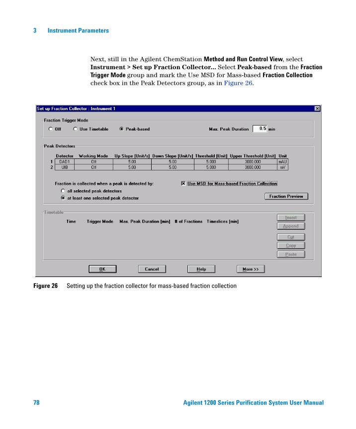
78 Agilent 1200 Series Purification System User Manual
3 Instrument Parameters
Next, still in the Agilent ChemStation Method and Run Control View, select Instrument > Set up Fraction Collector... Select Peak-based from the Fraction Trigger Mode group and mark the Use MSD for Mass-based Fraction Collection check box in the Peak Detectors group, as in Figure 26.
Figure 26 Setting up the fraction collector for mass-based fraction collection
Agilent 1200 Series Purification System User Manual 79
Instrument Parameters 3
When the Use MSD for Mass-based Fraction Collection option is selected, the parameters in the MSD Fraction Collection panel for the Agilent ChemStation method control the fraction collection. Other UV or analog (UIB) signals can be configured in the Set up Fraction Collector panel, and these signals can be used along with the MSD signal for triggering fraction collection. See “Fraction Collector” on page 67 for a discussion of the other parameters and functions in the Setup Fraction Collector panel.
If your system is configured for mass-based fraction collection, two dialog boxes are used to set up the Agilent ChemStation to monitor and even trigger the process based on mass or time:
• MSD Fraction Collection Dialog Box
• MSD Fraction Collection Parameters Dialog Box
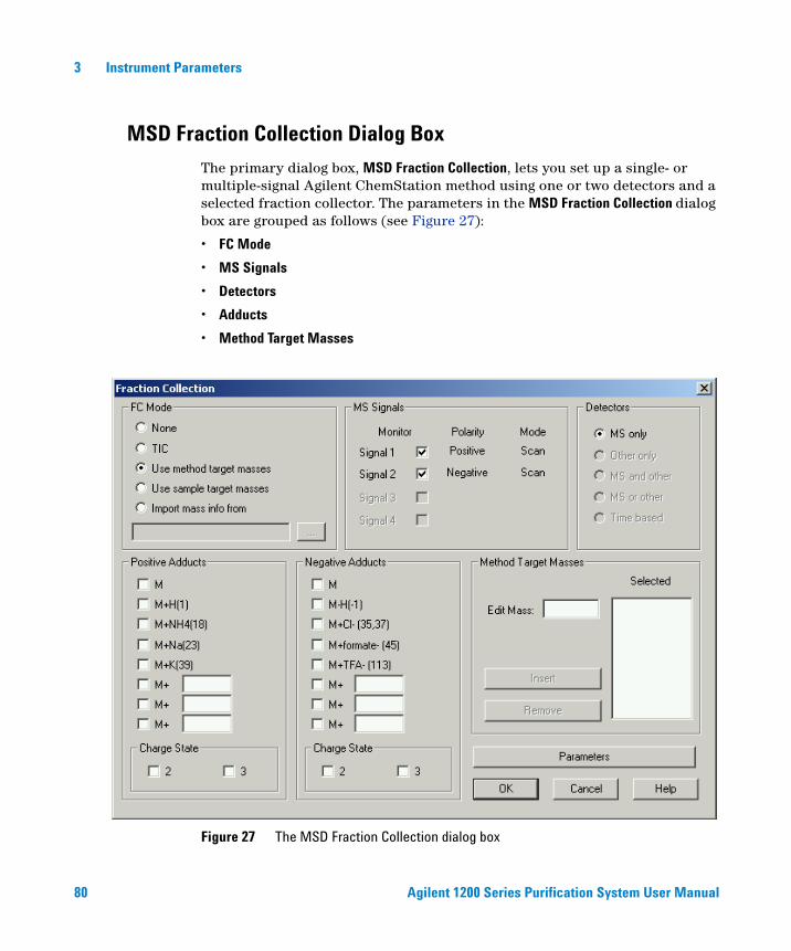
80 Agilent 1200 Series Purification System User Manual
3 Instrument Parameters
MSD Fraction Collection Dialog Box
The primary dialog box, MSD Fraction Collection, lets you set up a single- or multiple-signal Agilent ChemStation method using one or two detectors and a selected fraction collector. The parameters in the MSD Fraction Collection dialog box are grouped as follows (see Figure 27):
• FC Mode
• MS Signals
• Detectors
• Adducts
• Method Target Masses
Figure 27 The MSD Fraction Collection dialog box
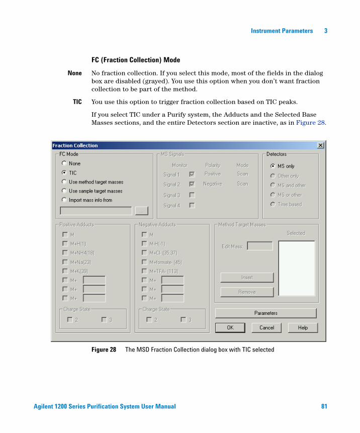
Agilent 1200 Series Purification System User Manual 81
Instrument Parameters 3
FC (Fraction Collection) Mode
None No fraction collection. If you select this mode, most of the fields in the dialog box are disabled (grayed). You use this option when you don’t want fraction collection to be part of the method.
TIC You use this option to trigger fraction collection based on TIC peaks.
If you select TIC under a Purify system, the Adducts and the Selected Base Masses sections, and the entire Detectors section are inactive, as in Figure 28.
Figure 28 The MSD Fraction Collection dialog box with TIC selected
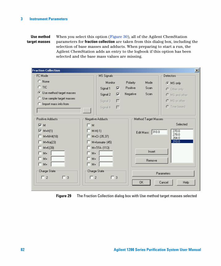
82 Agilent 1200 Series Purification System User Manual
3 Instrument Parameters
Use methodtarget masses
When you select this option (Figure 30), all of the Agilent ChemStation parameters for fraction collection are taken from this dialog box, including the selection of base masses and adducts. When preparing to start a run, the Agilent ChemStation adds an entry to the logbook if this option has been selected and the base mass values are missing.
Figure 29 The Fraction Collection dialog box with Use method target masses selected
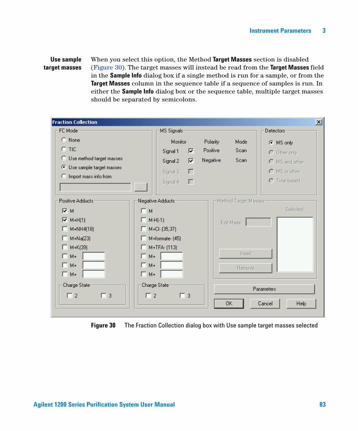
Agilent 1200 Series Purification System User Manual 83
Instrument Parameters 3
Use sampletarget masses
When you select this option, the Method Target Masses section is disabled (Figure 30). The target masses will instead be read from the Target Masses field in the Sample Info dialog box if a single method is run for a sample, or from the Target Masses column in the sequence table if a sequence of samples is run. In either the Sample Info dialog box or the sequence table, multiple target masses should be separated by semicolons.
Figure 30 The Fraction Collection dialog box with Use sample target masses selected
84 Agilent 1200 Series Purification System User Manual
3 Instrument Parameters
Import mass info When you select this option, the ability to enter base masses manually is disabled (Figure 19). The Browse button is enabled so that you can use a CSV (comma separated values) file to import base masses. You need to select the CSV file using Browse; you cannot type a CSV file path and name directly into the field.
The CSV file is a one line file with the following format:
BaseMass1,BaseMass2,BaseMass3,…
A special CSV file C:\HPCHEM\CORE\BASEMASS.CSV (where C: is the disk volume which contains the Agilent ChemStation software) exists when the LC/MSD Agilent ChemStation is used with the Purification/Hi Throughput software. At the beginning of each run, the Purification software will update this BASEMASS.CSV file with base masses corresponding to the “expected masses” specified in the study list for the sample that is to be run.
Since each sample will likely contain different compounds with different molecular ions, different base masses would need to be specified for each sample. Instead of selecting Use Method Info and entering just one set of base masses in the MSD Fraction Collection dialog box, select Import Mass Info and specify the CSV file C:\HPCHEM\CORE\BASEMASS.CSV. Then in the study enter the expected masses for each sample. In this way, the different expected masses for each sample will be used as the base masses for MSD Fraction Collection.
The license number for the G2263AA Mass-Based Fraction Collection add-on software must be installed in order to be able to enter expected masses for samples in the study.
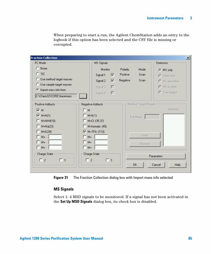
Agilent 1200 Series Purification System User Manual 85
Instrument Parameters 3
When preparing to start a run, the Agilent ChemStation adds an entry to the logbook if this option has been selected and the CSV file is missing or corrupted.
MS Signals
Select 1- 4 MSD signals to be monitored. If a signal has not been activated in the Set Up MSD Signals dialog box, its check box is disabled.
Figure 31 The Fraction Collection dialog box with Import mass info selected
86 Agilent 1200 Series Purification System User Manual
3 Instrument Parameters
Detectors
MS only Specifies use of the MSD as the only detector for fraction collection. If you have selected Use Method Target Masses, you need to specify base masses in the Selected Base Masses group (see “Method Target Masses” on page 87); if you have selected Import Mass Info, the base masses are imported from the specified CSV file. Note that when the optional Purify system is running, the entire Detectors section is disabled, and MS only is automatically selected.
Adducts
The Adducts group has separate sections for Positive and Negative ions. Adducts in the positive ion section will be monitored in all positive ion signals and adducts in the negative ion section will be monitored in all negative ion signals.
Predefined and user-defined adducts can be added or deleted by marking the corresponding check boxes.
The predefined adducts for positive ion include:
Base mass (M)
Hydrogen, H (M + 1)
Ammonium, NH4 (M + 18)
Sodium, Na (M + 23)
Potassium, K (M + 39)
For negative ion, a hydrogen abstraction (M - 1)- is also predefined.
You can define other adducts by activating a positive or negative ion check box and entering the number (+ or -) to add to the base mass. For example, to monitor a TFA (trifluoroacetic acid) adduct in negative ion mode, you select one of the boxes under the Negative heading and enter 113. The result would monitor the base mass in the negative ion signals, which would be described as (M + 113)-.
NOTE You configure time-based fraction collection through the Setup Fraction Collection dialog box for the Fraction Collector module, if a fraction collector is present in the system (see Figure 26 on page 78).
Agilent 1200 Series Purification System User Manual 87
Instrument Parameters 3
The adduct limits are 1.0 - 999.9 for either Positive or Negative signals.
Note that the number of adducts you select multiplied by the number of base masses you select should not exceed 16.
Method Target Masses
When the MSD is used as a detector and FC Mode is Use Method Info, you must enter one or more base masses in the Method Target Masses group of the dialog box, using the edit buttons Insert and Remove. The selected mass is displayed in the Selected list.
Enter a mass and click Insert to add it to the Selected list. To edit a mass in the list, select it and the mass is displayed in the edit field. To remove a mass, select it and click Remove.
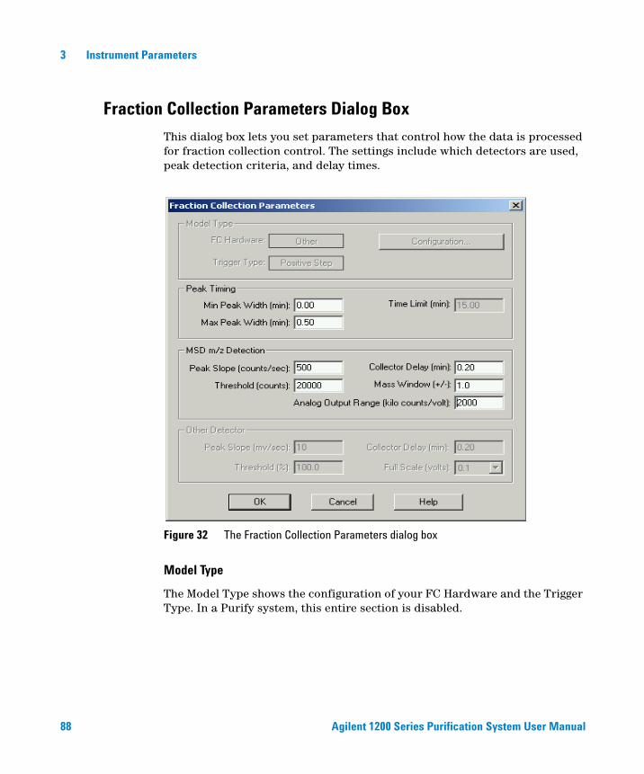
88 Agilent 1200 Series Purification System User Manual
3 Instrument Parameters
Fraction Collection Parameters Dialog Box
This dialog box lets you set parameters that control how the data is processed for fraction collection control. The settings include which detectors are used, peak detection criteria, and delay times.
Model Type
The Model Type shows the configuration of your FC Hardware and the Trigger Type. In a Purify system, this entire section is disabled.
Figure 32 The Fraction Collection Parameters dialog box
Agilent 1200 Series Purification System User Manual 89
Instrument Parameters 3
Peak Timing
These parameters are used to set limits on the expected peak width, or to advance to the next fraction collection vial if the peak must span multiple vials.
If the fraction collector is being controlled via an analog signal, these parameters have no effect.
Min Peak Width (min)
This parameter is used to eliminate spikes in the chromatogram. If a mass peak is narrower than the minimum value, the fraction collection relay is not triggered.
Note that the minimum peak width must be less than the MSD Collector Delay. If the delay is less than the minimum peak width, there is no way to cancel the fraction collection signal.
Default 0. 0 min.
Max Peak Width (min)
This parameter protects against peaks that never reach the peak termination conditions. This might happen if a rising baseline prevents a signal from going below threshold.
Default 0.50 min.
When the Max Peak Width time is reached, fraction collection for the current fraction stops. This is different than the Time Limit parameter, where the fraction collector advances to the next position and continues collecting the fraction when the Time Limit is reached.
NOTE Time Limit is not used with the Purify system.
90 Agilent 1200 Series Purification System User Manual
3 Instrument Parameters
Time Limit (min)
This parameter is used to prevent a fraction collection vial overflow. The correct value can be calculated from the fraction collection vial volume and the LC flow rate as follows:
Note that many fraction collectors can be programmed to advance the vials based on time. If this function is to be controlled from the fraction collector, then set the time limit to a number much larger than the Max Peak Width.
Default 15.00 min.
This parameter is disabled on Purify systems. On Purify systems, the fraction collector module and the Agilent ChemStation software know the volume of the installed fraction collection vessel, and overflow of the vessel is automatically prevented.
MSD m/z Detection
These parameters determine whether a sample is collected.
Peak Slope (counts/sec)
The signal must be above this value for a sample to be collected.
Default 500 counts/sec.
For mass-based fraction collection, the specified ions (base mass plus adduct mass) are extracted from the scan. If multiple ions are being monitored, the largest ion at any point in time is evaluated to see if criteria are met.
Requiring a minimum slope protects against a sloping baseline that might go above threshold. If the slope is set to zero, then only the threshold is used.
Signal must exceed threshold abundance and slope to start
Fraction collection starts when the signal level at a given point exceeds the threshold AND the slope is greater than the specified peak slope (in counts/second).
Signal must fall below threshold abundance AND have negative slope less than threshold to stop
Time limit (min) Vial volume (ml)Flow rate (ml/min)---------------------------------------------=
Agilent 1200 Series Purification System User Manual 91
Instrument Parameters 3
The signal slope decreases to zero and becomes negative on the down side of the peak. After the negative slope is over the specified peak slope again, then the peak ends when a given point is below the threshold AND the negative slope is lower than the specified peak slope.
Slope calculation
For a given point P3, the slope is calculated using two points midway between P1 and P2.
Peak detection with unresolved peaks
A peak is considered terminated when a different ion becomes the largest, even if the peak stop criteria have not been met. This feature allows peaks that are not well resolved to be separated. This allows you to have lower thresholds than would otherwise be practical, catching more of the peak.
If two ions are being monitored that are very close to each other in abundance, there is a danger that a peak could be split into two or more vials. While this is not desirable, it is better to have a single peak in two vials than two peaks in one vial.
Threshold (counts)
The signal must be above this value for a sample to be collected. If Peak Slope is above zero, then both the threshold and peak slope criteria must be met to collect a peak.
Default 2000 counts.
Collector Delay (min)
Collector Delay is the time interval between when the signal peak enters the MSD and when it enters the fraction collection hardware. This value is always at least 0.01 min later than the value for Min Peak Width.
Default 0.01 min.
When a destructive detector, such as a mass spectrometer or evaporative light-scattering detector (ELSD) is used, a splitter must be included so that the sample can be analyzed while still passing most of the sample along to the fraction collector. The splitter alters the flow rate through both, so a simple volume-flow rate calculation cannot be used. The split ratio, for a given splitter, can vary based on the solvent composition (viscosity) and any changes in tubing restriction that may occur over time.
92 Agilent 1200 Series Purification System User Manual
3 Instrument Parameters
In fact, the split ratio can change over time during a gradient run. As a result, the actual delay times need to be measured for any changes in flow rate, solvent composition or tubing and connections. Refer to “Delay Volume Calibration” on page 93 for details. The split ratio may also change over time if any of the tubing of the splitter becomes partially restricted.
Mass Window (+/-)
Mass Window is a mass range in amu to monitor. For example, for mass 195.4 and a Mass Window of 1.0, the ChemStation monitors from 194.4 to 196.4 daltons.
Default 1.0.
Analog Output Range (kilo counts/volt)
Analog Output Range is a scaling factor for the analog output signal. This value should be set so that the largest expected peak yields a voltage that matches the fraction collector’s maximum input voltage. For example, if the fraction collector expects a maximum voltage of 10 mV, and the largest expected peak is 200,000 counts, the scaling factor can be calculated as follows:
Default 2000 kilo counts/volts
Other Detector
These are parameters that determine whether a sample is detected in the analog input signal. This entire section is disabled for a Purify system.
00 counts 1000×( ) 0.01 volts⁄ 20000 counts 1000× vol⁄=
Agilent 1200 Series Purification System User Manual 93
Instrument Parameters 3
Delay Volume Calibration
The delay volume calibration measures the delay volume (or time, if an LC-MSD is used for the delay calibration) between a detector (a source of a peak trigger) and a fraction collector. The procedure determines the delay volume relative to all configured detectors. It is available for a Fraction Collector AS, or for a Fraction Collector PS with an additional Fraction Delay Sensor installed.
CAUTION The detector peakwidth has an influence on the delay time of the peak; therefore, we recommend that you use the maximum flow rates for the peakwidths given in Table 10 on page 116 or Table 11 on page 116. Use of higher flow rates will result in missed peaks unless the analog signal delay is taken into account:
Minimum required delay volume signal delay flow×=
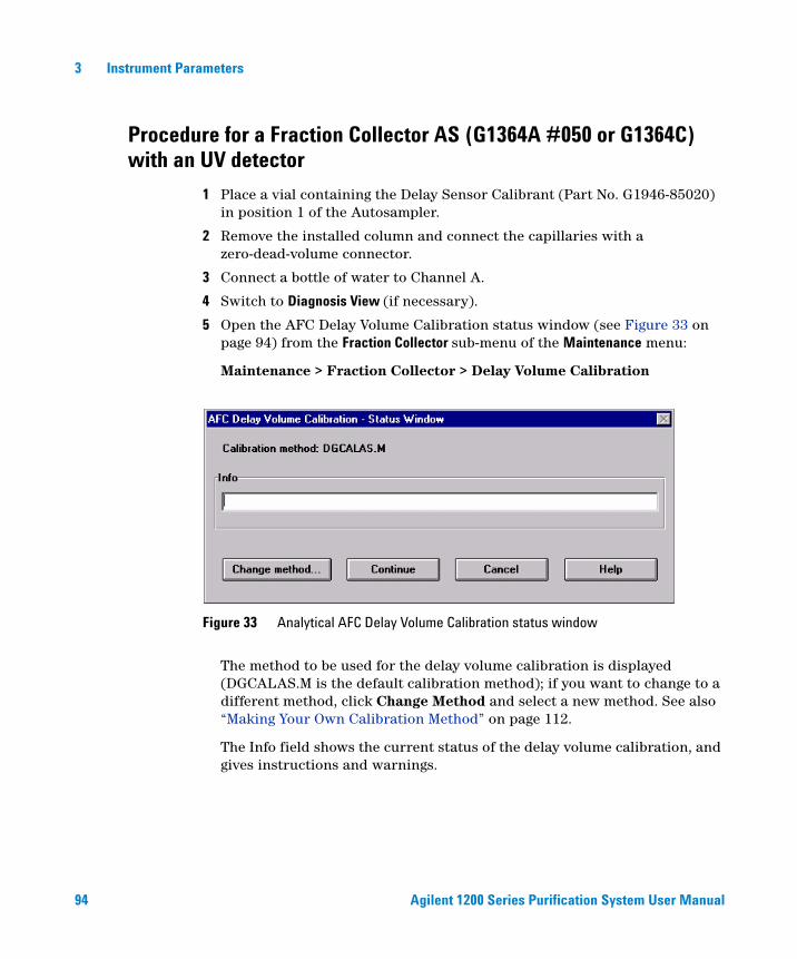
94 Agilent 1200 Series Purification System User Manual
3 Instrument Parameters
Procedure for a Fraction Collector AS (G1364A #050 or G1364C) with an UV detector
1 Place a vial containing the Delay Sensor Calibrant (Part No. G1946-85020) in position 1 of the Autosampler.
2 Remove the installed column and connect the capillaries with a zero-dead-volume connector.
3 Connect a bottle of water to Channel A.
4 Switch to Diagnosis View (if necessary).
5 Open the AFC Delay Volume Calibration status window (see Figure 33 on page 94) from the Fraction Collector sub-menu of the Maintenance menu:
Maintenance > Fraction Collector > Delay Volume Calibration
The method to be used for the delay volume calibration is displayed (DGCALAS.M is the default calibration method); if you want to change to a different method, click Change Method and select a new method. See also “Making Your Own Calibration Method” on page 112.
The Info field shows the current status of the delay volume calibration, and gives instructions and warnings.
Figure 33 Analytical AFC Delay Volume Calibration status window
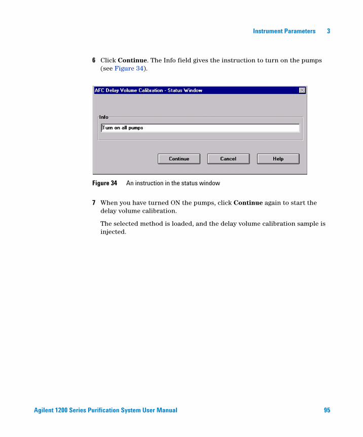
Agilent 1200 Series Purification System User Manual 95
Instrument Parameters 3
6 Click Continue. The Info field gives the instruction to turn on the pumps (see Figure 34).
7 When you have turned ON the pumps, click Continue again to start the delay volume calibration.
The selected method is loaded, and the delay volume calibration sample is injected.
Figure 34 An instruction in the status window

96 Agilent 1200 Series Purification System User Manual
3 Instrument Parameters
8 When the calibration run has finished, click OK. The Calibration Results panel (see Figure 35) is displayed.
The Calibration Results panel contains a results table and the acquired chromatograms from the detector(s) and the fraction collector delay sensor. The results table contains
• the name and serial number of the detector,
• the current delay volume (stored in the fraction collector configuration),
• the calculated delay volume from the calibration.
You can click Print to print the Calibration Results panel.
Figure 35 Calibration Results panel
Agilent 1200 Series Purification System User Manual 97
Instrument Parameters 3
9 If you want to store the calculated delay volume in the fraction collector configuration, click Calibrate. A confirmation dialog box is displayed when the delay volume has been stored; click OK to close the confirmation.
If you do not want to store the calculated delay volume in the fraction collector configuration, click Close. A confirmation dialog box is displayed; click OK to close the confirmation or Cancel to return to the Calibration Results panel.
NOTE If two or three fraction collectors are configured, you can calibrate the delay volume for the first fraction collector only (the delay volume calibration menu is accessible only for Fraction Collector 1, which is the fraction collector that appears first in the list of configured Agilent 1200 modules).
The calculated delay volume is used for all fraction collectors; therefore, the volume (tubing) between the selection valve and each installed fraction collector must be identical.
You still have the possibility to manually change the volumes for each fraction collector separately in the configure screen of the ChemStation for each module.
98 Agilent 1200 Series Purification System User Manual
3 Instrument Parameters
Procedure for a Fraction Collector PS (G1364A or G1364B) with an UV detector
1 Place a vial containing the Delay Sensor Calibrant (Part No. G1946-85020) in position 1 of the Autosampler.
2 Remove the installed column and connect the capillaries with a zero-dead-volume connector.
3 Connect a bottle of water to Channel A.
4 Remove the installed tray.
5 Install the delay sensor (G1364A, only. The delay sensor is already pre-installed in the G1364B).
6 Switch to Diagnosis View (if necessary).
7 Open the AFC Delay Volume Calibration status window (see Figure 36) from the Fraction Collector sub-menu of the Maintenance menu:
Maintenance > Fraction Collector > Delay Volume Calibration
CAUTION The detector peakwidth has an influence on the delay time of the peak; therefore, we recommend that you use the maximum flow rates for the peakwidths given in Table 10 on page 116 or Table 11 on page 116. Use of higher flow rates will result in missed peaks unless the analog signal delay is taken into account:
NOTE There are some differences in this procedure, depending wether you use the G1364A or the G1364B version. Please follow the instructions for the correct version of the instrument.
Minimum required delay volume signal delay flow×=
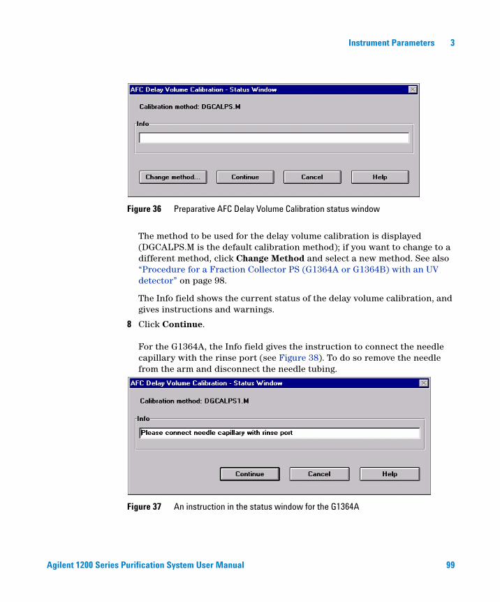
Agilent 1200 Series Purification System User Manual 99
Instrument Parameters 3
The method to be used for the delay volume calibration is displayed (DGCALPS.M is the default calibration method); if you want to change to a different method, click Change Method and select a new method. See also “Procedure for a Fraction Collector PS (G1364A or G1364B) with an UV detector” on page 98.
The Info field shows the current status of the delay volume calibration, and gives instructions and warnings.
8 Click Continue.
For the G1364A, the Info field gives the instruction to connect the needle capillary with the rinse port (see Figure 38). To do so remove the needle from the arm and disconnect the needle tubing.
Figure 36 Preparative AFC Delay Volume Calibration status window
Figure 37 An instruction in the status window for the G1364A

100 Agilent 1200 Series Purification System User Manual
3 Instrument Parameters
For the G1364B, the Info field gives the instruction to install the needle adapter to the needle arm (see Figure 38).
9 When you have closed the door, click Continue again to start the delay volume calibration.
The selected method is loaded, and the delay volume calibration sample is injected.
Figure 38 An instruction in the status window for the G1364B
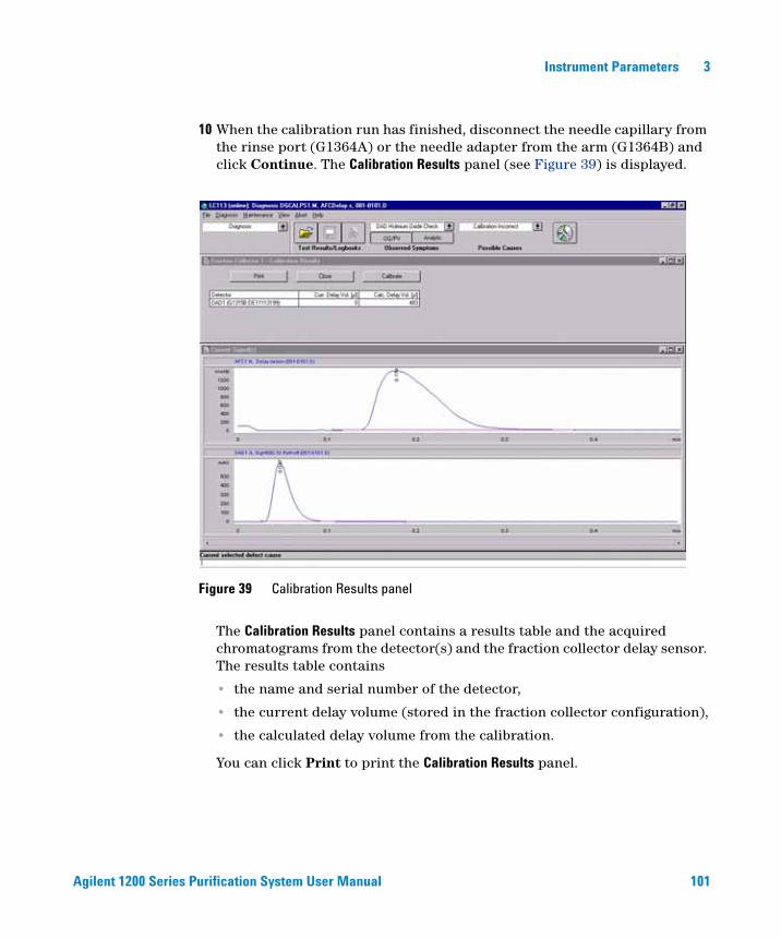
Agilent 1200 Series Purification System User Manual 101
Instrument Parameters 3
10 When the calibration run has finished, disconnect the needle capillary from the rinse port (G1364A) or the needle adapter from the arm (G1364B) and click Continue. The Calibration Results panel (see Figure 39) is displayed.
The Calibration Results panel contains a results table and the acquired chromatograms from the detector(s) and the fraction collector delay sensor. The results table contains
• the name and serial number of the detector,
• the current delay volume (stored in the fraction collector configuration),
• the calculated delay volume from the calibration.
You can click Print to print the Calibration Results panel.
Figure 39 Calibration Results panel
102 Agilent 1200 Series Purification System User Manual
3 Instrument Parameters
11 If you want to store the calculated delay volume in the fraction collector configuration, click Calibrate. A confirmation dialog box is displayed when the delay volume has been stored; click OK to close the confirmation.
If you do not want to store the calculated delay volume in the fraction collector configuration, click Close. A confirmation dialog box is displayed; click OK to close the confirmation or Cancel button return to the Calibration Results panel.
Procedure for a Fraction Collector AS with an MSD
1 Place a vial with the Delay Sensor calibrant (Part No. G1946-85020) in position 1 of the Autosampler.
2 Remove the installed column and connect the capillaries with a zero-dead-volume connector or a mixer (Part No. 79835-87330).
3 Connect a bottle of water to Channel A of the main pump.
4 Connect a bottle of water with 0.1% acetic acid or ammonium formate to the make-up pump.
5 Load the method DGCALAS.M and adjust the flow in the main pump to the flow you will be using for the analysis.
NOTE If two or three fraction collectors are configured, you can calibrate the delay volume for the first fraction collector only (the delay volume calibration menu is accessible only for Fraction Collector 1, which is the fraction collector that appears first in the list of configured Agilent 1200 Series modules).
The calculated delay volume is used for all fraction collectors; therefore, the volume (tubing) between the selection valve and each installed fraction collector must be identical.
You still have the possibility to manually change the volumes for each fraction collector separately.
CAUTION Unlike for UV detectors, the delay calibration for the MSD needs to be performed whenever the flow rate is changed.
Agilent 1200 Series Purification System User Manual 103
Instrument Parameters 3
6 Set the flow of the make-up pump to the flow rate you will be using for your analysis.
7 Set the active splitter to a setting of 3.
8 Save the method to a new name.
9 Go to Diagnostics menu; select Delay volume Calibration from the Fraction Collector Sub-menu within the Maintenance menu.
10 Press Change method... to select the method you created. The new method name appears on the info line.
11 Start the active splitter.
12 Press Continue to execute the Delay Volume Calibration
The selected method is loaded and the Delay Calibration Sample Injected.
13 When the Calibration Run is finished, press OK.
14 Examine the value for the MSD Calculated Delay time.
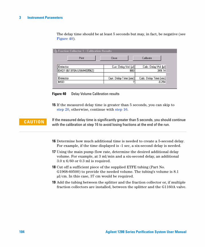
104 Agilent 1200 Series Purification System User Manual
3 Instrument Parameters
The delay time should be at least 5 seconds but may, in fact, be negative (see Figure 40).
15 If the measured delay time is greater than 5 seconds, you can skip to step 20, otherwise, continue with step 16.
16 Determine how much additional time is needed to create a 5-second delay. For example, if the time displayed is -1 sec, a six-second delay is needed.
17 Using the main pump flow rate, determine the desired additional delay volume. For example, at 3 ml/min and a six-second delay, an additional 3.0 x 6/60 or 0.3 ml is required.
18 Cut off a sufficient piece of the supplied ETFE tubing (Part No. G1968-60500) to provide the needed volume. The tubing's volume is 8.1 µl/cm. In this case, 37 cm would be required.
19 Add the tubing between the splitter and the fraction collector or, if multiple fraction collectors are installed, between the splitter and the G1160A valve.
Figure 40 Delay Volume Calibration results
CAUTION If the measured delay time is significantly greater than 5 seconds, you should continue with the calibration at step 16 to avoid losing fractions at the end of the run.
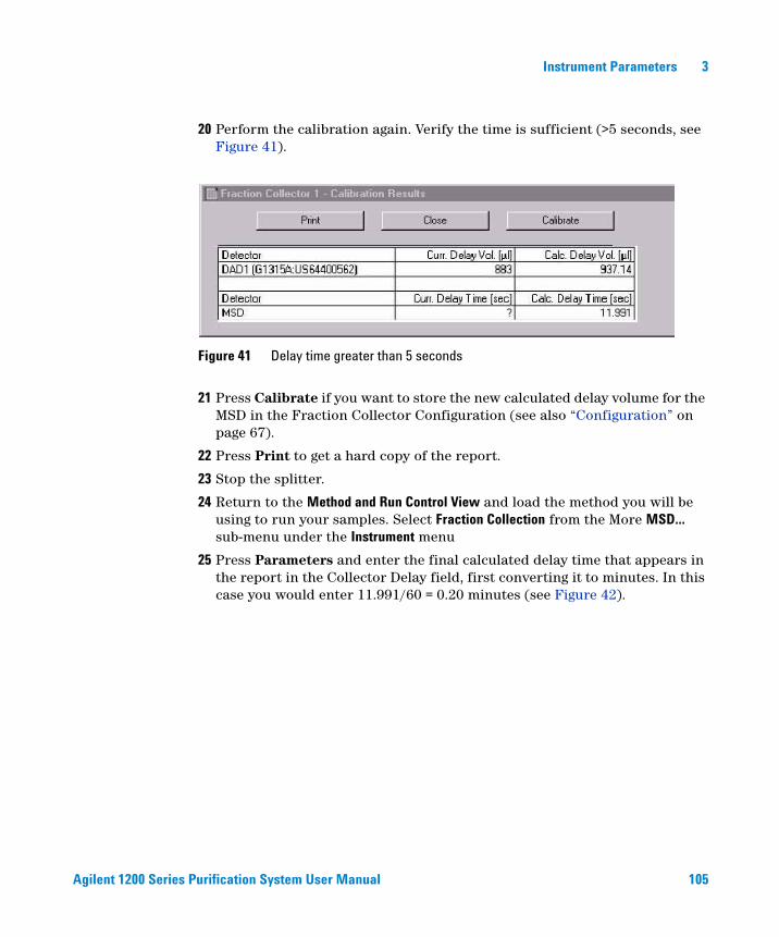
Agilent 1200 Series Purification System User Manual 105
Instrument Parameters 3
20 Perform the calibration again. Verify the time is sufficient (>5 seconds, see Figure 41).
21 Press Calibrate if you want to store the new calculated delay volume for the MSD in the Fraction Collector Configuration (see also “Configuration” on page 67).
22 Press Print to get a hard copy of the report.
23 Stop the splitter.
24 Return to the Method and Run Control View and load the method you will be using to run your samples. Select Fraction Collection from the More MSD... sub-menu under the Instrument menu
25 Press Parameters and enter the final calculated delay time that appears in the report in the Collector Delay field, first converting it to minutes. In this case you would enter 11.991/60 = 0.20 minutes (see Figure 42).
Figure 41 Delay time greater than 5 seconds

106 Agilent 1200 Series Purification System User Manual
3 Instrument Parameters
26 Save the method.
Figure 42 Fraction Collection Parameters dialog box with delay volume entry
NOTE If you anticipate running samples at a variety of flow rates, it is best to calibrate at the highest likely flow rate first and install the appropriate length tubing. This way, there will be sufficient delay for the lower flow rates and new lengths will not need to be cut.
Agilent 1200 Series Purification System User Manual 107
Instrument Parameters 3
Procedure for a Fraction Collector PS with an MSD
1 Place a vial with the Delay Sensor Calibrant (Part No. G1946-85020) in position 1 of the Autosampler.
2 Remove the installed column and connect the capillaries with a zero-dead-volume connector or a mixer (Part No. 79835-87330).
3 Connect a bottle of water to Channel A of the main pump.
4 Connect a bottle of water with 0.1% acetic acid or ammonium formate to the make-up pump.
5 Load the method DGCALPS.M and adjust the flow in the main pump to the flow you will be using for the analysis.
CAUTION Unlike for UV detectors, the delay calibration for the MSD needs to be performed whenever the flow rate is changed.
108 Agilent 1200 Series Purification System User Manual
3 Instrument Parameters
6 Set the flow of the make-up pump to the flow rate you will be using for your analysis.
7 Set the active splitter to a setting of 3.
8 Save the method to a new name.
9 If the Delay Sensor is not already installed, remove the tray installed in the fraction collector.
10 Install the Delay Sensor.
11 Go to Diagnostics menu; select Delay volume Calibration from the Fraction Collector sub-menu within the Maintenance menu.
12 Press Change method... to select the method you created. The new method name appears on the info line.
13 Start the active splitter.
14 Press Continue to execute the Delay Volume Calibration.
15 When prompted on the Info line, disconnect the needle from the transport arm and disconnect the tubing (for the PS version of G1364A) or install the FDS-adapter to the fraction collector arm (G1364B).
16 Connect the tubing of the transport arm to the union in the rinse port (G1364A, only).
17 Close the door and press Continue.
The selected method is loaded and the Delay Calibration Sample Injected.
18 When prompted, disconnect the tubing from the rinse port union (G1364A) or remove the FDS adapter from the arm (G1364B).
19 If the Calibration Run is finished, press OK.
20 Examine the value for the MSD Calculated Delay time.
The delay time should be at least 5 seconds but may, in fact, be negative (see Figure 43).

Agilent 1200 Series Purification System User Manual 109
Instrument Parameters 3
21 If the measured delay time is greater than 5 seconds, you can skip to step 27, otherwise, continue with step 22.
22 Determine how much additional time is needed to create a 5-second delay. For example, if the time displayed is -1 sec, a six-second delay is needed.
23 Using the main pump flow rate, determine the desired additional delay volume. For example, at 20 ml/min and a six-second delay, an additional 20.0 x 6/60 or 2.0 ml is required.
24 Cut off a sufficient piece of the supplied ETFE tubing (Part No. G1968-60500) to provide the needed volume. The tubing's volume is 8.1 µl/cm. In this case, 247 cm would be required.
Figure 43 Delay Volume Calibration results
CAUTION If the measured delay time is significantly greater than 5 seconds, you should continue with the calibration at step 22 to avoid losing fractions at the end of the run.
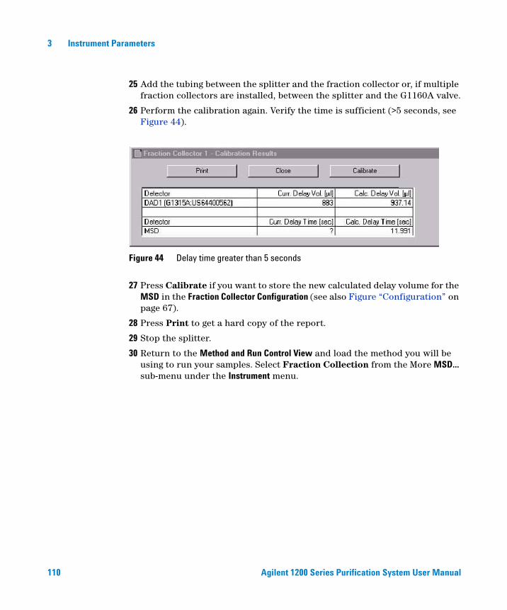
110 Agilent 1200 Series Purification System User Manual
3 Instrument Parameters
25 Add the tubing between the splitter and the fraction collector or, if multiple fraction collectors are installed, between the splitter and the G1160A valve.
26 Perform the calibration again. Verify the time is sufficient (>5 seconds, see Figure 44).
27 Press Calibrate if you want to store the new calculated delay volume for the MSD in the Fraction Collector Configuration (see also Figure “Configuration” on page 67).
28 Press Print to get a hard copy of the report.
29 Stop the splitter.
30 Return to the Method and Run Control View and load the method you will be using to run your samples. Select Fraction Collection from the More MSD... sub-menu under the Instrument menu.
Figure 44 Delay time greater than 5 seconds
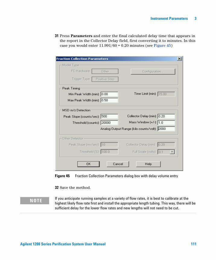
Agilent 1200 Series Purification System User Manual 111
Instrument Parameters 3
31 Press Parameters and enter the final calculated delay time that appears in the report in the Collector Delay field, first converting it to minutes. In this case you would enter 11.991/60 = 0.20 minutes (see Figure 45)
32 Save the method.
Figure 45 Fraction Collection Parameters dialog box with delay volume entry
NOTE If you anticipate running samples at a variety of flow rates, it is best to calibrate at the highest likely flow rate first and install the appropriate length tubing. This way, there will be sufficient delay for the lower flow rates and new lengths will not need to be cut.

112 Agilent 1200 Series Purification System User Manual
3 Instrument Parameters
Making Your Own Calibration Method
You make your own calibration method by editing one of the default calibration methods:
1 Load the default calibration method: DGCALAS.M in the case of an analytical system and DGCALPS.M in the case of a preparative system.
2 Change the method parameters (flow, runtime, solvent composition, injection volume or detector parameters) to suit your adapted calibration procedure.
3 Save the method with a new name in the method folder for your instrument.
4 Follow the appropriate procedure as described in the previous sections for running the method.
Delay Volume Calculations (UV Detector)
Figure 46 shows how the delay volume calibration results are generated.
CAUTION The detector peakwidth has an influence on the delay time of the peak; therefore, we recommend that you use the maximum flow rates for the peakwidths given in Table 8 on page 115 or Table 9 on page 115. Use of higher flow rates will result in missed peaks unless the analog signal delay is taken into account:
Minimum required delay volume signal delay flow×=
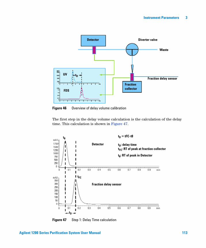
Agilent 1200 Series Purification System User Manual 113
Instrument Parameters 3
The first step in the delay volume calculation is the calculation of the delay time. This calculation is shown in Figure 47.
Figure 46 Overview of delay volume calibration
Figure 47 Step 1: Delay Time calculation
Detector
Fraction collector
Diverter valve
Waste
Fraction delay sensorUV
FDS
tD
t0
tFC
tD
Fraction delay sensor
Detector
tD = tFC-t0
tD: delay timetFC: RT of peak at fraction collector
t0: RT of peak in Detector

114 Agilent 1200 Series Purification System User Manual
3 Instrument Parameters
The calculation of the delay volume is shown in Figure 48. In Figure 48, the delay times tD1 and tD2, and the volumes VD1 and VD2, include the volume of the valve, which is corrected for in the delay volume calculation.
Maximum flow rates to avoid missing peaks
Because of the effect of the detector peakwidth settings on the delay time of a peak, the use of higher flow rates than those recommended in Table 8 on page 115 to Table 11 on page 116 will result in peaks being missed, unless you take into account the analog signal delay.
The maximum flow is calculated as
Figure 48 Step 2: Delay Volume Calculation
Detector
Fraction collector
Diverter valve
WasteVD1, tD1
VD2, tD2
VD1: Delay volume to be calculatedVD2: Internal volume (of the diverter valve plus the valve to needle tubing plus the rinse port to delay sensor tubing)v: flow rate
tD = tD1 + tD2 and VD = VD1 + VD2VD1 = VD - VD2VD1 = tD *v - VD2
Maximum flow Delay volume signal delay time⁄=
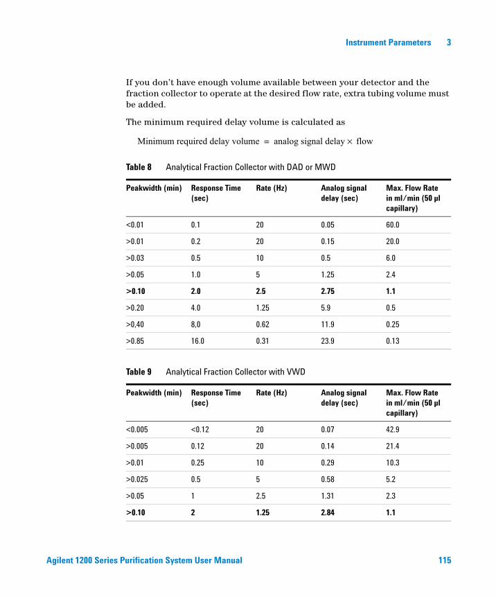
Agilent 1200 Series Purification System User Manual 115
Instrument Parameters 3
If you don’t have enough volume available between your detector and the fraction collector to operate at the desired flow rate, extra tubing volume must be added.
The minimum required delay volume is calculated as
Table 8 Analytical Fraction Collector with DAD or MWD
Peakwidth (min) Response Time (sec)
Rate (Hz) Analog signal delay (sec)
Max. Flow Rate in ml/min (50 µl capillary)
<0.01 0.1 20 0.05 60.0
>0.01 0.2 20 0.15 20.0
>0.03 0.5 10 0.5 6.0
>0.05 1.0 5 1.25 2.4
>0.10 2.0 2.5 2.75 1.1
>0.20 4.0 1.25 5.9 0.5
>0,40 8,0 0.62 11.9 0.25
>0.85 16.0 0.31 23.9 0.13
Table 9 Analytical Fraction Collector with VWD
Peakwidth (min) Response Time (sec)
Rate (Hz) Analog signal delay (sec)
Max. Flow Rate in ml/min (50 µl capillary)
<0.005 <0.12 20 0.07 42.9
>0.005 0.12 20 0.14 21.4
>0.01 0.25 10 0.29 10.3
>0.025 0.5 5 0.58 5.2
>0.05 1 2.5 1.31 2.3
>0.10 2 1.25 2.84 1.1
Minimum required delay volume analog signal delay flow×=
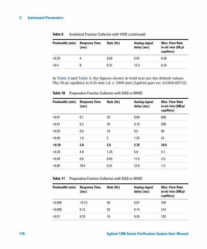
116 Agilent 1200 Series Purification System User Manual
3 Instrument Parameters
In Table 8 and Table 9, the figures shown in bold text are the default values. The 50 μl capillary is 0.25 mm i.d. × 1000 mm (Agilent part no. G1364-68712).
>0.20 4 0.62 5.97 0.50
>0.4 8 0.31 12.3 0.24
Table 10 Preparative Fraction Collector with DAD or MWD
Peakwidth (min) Response Time (sec)
Rate (Hz) Analog signal delay (sec)
Max. Flow Rate in ml/min (500 µl capillary)
<0.01 0.1 20 0.05 600
>0.01 0.2 20 0.15 200
>0.03 0.5 10 0.5 60
>0.05 1.0 5 1.25 24
>0.10 2.0 2.5 2.75 10.9
>0.20 4.0 1.25 5.9 5.1
>0,40 8,0 0.62 11.9 2.5
>0.85 16.0 0.31 23.9 1.3
Table 11 Preparative Fraction Collector with DAD or MWD
Peakwidth (min) Response Time (sec)
Rate (Hz) Analog signal delay (sec)
Max. Flow Rate in ml/min (500 µl capillary)
<0.005 <0.12 20 0.07 429
>0.005 0.12 20 0.14 214
>0.01 0.25 10 0.29 103
Table 9 Analytical Fraction Collector with VWD (continued)
Peakwidth (min) Response Time (sec)
Rate (Hz) Analog signal delay (sec)
Max. Flow Rate in ml/min (50 µl capillary)
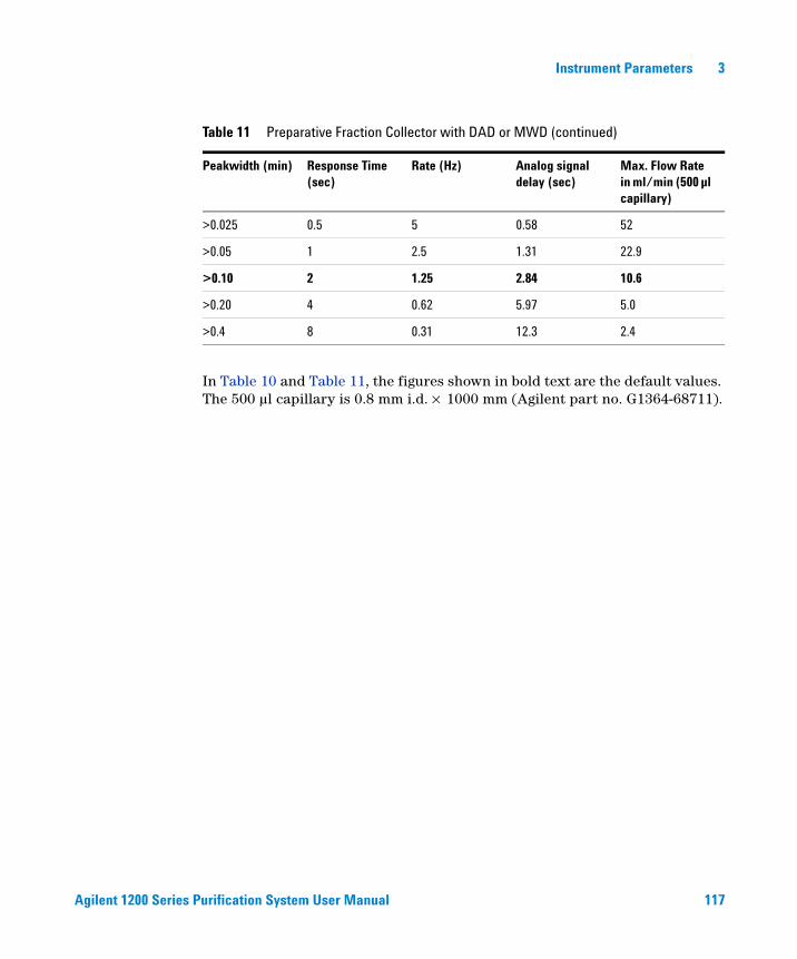
Agilent 1200 Series Purification System User Manual 117
Instrument Parameters 3
In Table 10 and Table 11, the figures shown in bold text are the default values. The 500 µl capillary is 0.8 mm i.d. × 1000 mm (Agilent part no. G1364-68711).
>0.025 0.5 5 0.58 52
>0.05 1 2.5 1.31 22.9
>0.10 2 1.25 2.84 10.6
>0.20 4 0.62 5.97 5.0
>0.4 8 0.31 12.3 2.4
Table 11 Preparative Fraction Collector with DAD or MWD (continued)
Peakwidth (min) Response Time (sec)
Rate (Hz) Analog signal delay (sec)
Max. Flow Rate in ml/min (500 µl capillary)

118 Agilent 1200 Series Purification System User Manual
3 Instrument Parameters
119
Agilent 1200 Series Purification SystemUser Manual
Agilent Technologies
4*
Menus and Views
Mode 120
Main Panel 121
Menu Bar 125
Tool Bar 131
This chapter describes the menu structure and toolbar buttons.
*
120 Agilent 1200 Series Purification System User Manual
4 Menus and Views
Mode
The Purification/Hi Throughput software can be used in two modes, each of which has its own menu structure and toolbar buttons.
View Mode
You use View mode to view the details of a study once it has been created and run. You cannot create, edit or run a study in View mode.
Select Mode (Edit)
You use Select mode to create a new study or edit an existing study, and to run a study. You cannot view the results of a study in Select mode.

Agilent 1200 Series Purification System User Manual 121
Menus and Views 4
Main Panel
The main panel of the Purification/Hi Throughput application is divided into two main areas, the explorer at the left and the workspace at the right. Above the two main areas are the menu bar and toolbar, below are the status bar and message line (if displayed), see Figure 49.
Explorer
The Explorer contains a tree view of all the studies that have been opened in the current session, that is, since the application was started. The current study is highlighted in blue; the study node expands to show the methods and samples that are associated with the study. You can re-open any one of the studies in the explorer by selecting it. The explorer is cleared when the software is re-started.
Figure 49 Purification/Hi Throughput Main Panel
Menu barToolbar
Workspace
Status bar
Explorer
Message line
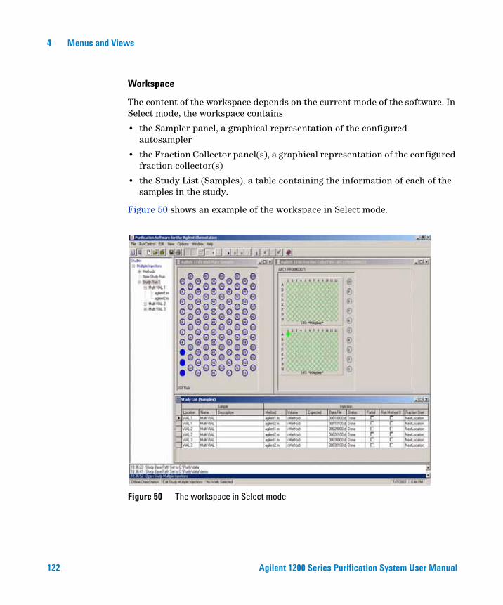
122 Agilent 1200 Series Purification System User Manual
4 Menus and Views
Workspace
The content of the workspace depends on the current mode of the software. In Select mode, the workspace contains
• the Sampler panel, a graphical representation of the configured autosampler
• the Fraction Collector panel(s), a graphical representation of the configured fraction collector(s)
• the Study List (Samples), a table containing the information of each of the samples in the study.
Figure 50 shows an example of the workspace in Select mode.
Figure 50 The workspace in Select mode

Agilent 1200 Series Purification System User Manual 123
Menus and Views 4
The items that are displayed in the workspace in Select mode are fixed, and you cannot change them. You can, however, minimize or maximize each of the items, resize the panels and adjust their positions in the workspace.
In View mode, you can select the worksheet items to display. In addition to the items displayed in Select mode (see above), you can display
• the Study Parameters dialog box, which is a read-only version of the Setup Study Parameters dialog box. This contains all the set-up parameters for the current study (see “Setting Up the Study Parameters” on page 141 for an explanation of the parameters)
• The Study List (Injections), which contains the details of all the injections in the study and the fractions collected for each of them.
• The Result Panel, which contains details of all the results in the study. You can also configure the Results Panel from the View menu.
Configuring the Tables
The width and sequence of the columns in all tables can be customized.
Changing the width of a column
To change the width of a column,
1 Place the mouse pointer over the right side of the column heading, so that it changes to a horizontal double-headed arrow.
2 Hold the left mouse button down and adjust the width of the column.
To minimize the column width,
1 Click the right mouse button in the column heading. The width of the column, and any columns beneath it, is minimized.
To reset a minimized column,
1 Click the right mouse button in the minimized column heading. The width of the column, and any columns beneath it, is reset to its default display width.
124 Agilent 1200 Series Purification System User Manual
4 Menus and Views
Changing the sequence of the columns
You can change the sequence of the columns either by a drag-and-drop method, or by using a drop-down menu.
To change the sequence by the drag-and-drop method,
1 Click and hold the left mouse button in the column heading.
2 Drag the column outline to its desired position and release the mouse button. The column is inserted into the table at this position.
To change the sequence using the drop-down menu,
1 Click the left mouse button in the column heading. A down-arrow is displayed at the right of the heading.
2 Click the down arrow to reveal the drop-down menu containing a list of all columns in the table or sub-table.
3 Select the name of the column that you want to move to this position. The positions of the current column and the selected column are switched.
Agilent 1200 Series Purification System User Manual 125
Menus and Views 4
Menu Bar
File
The following items are available in the File menu:
New Study
Starts the Study Wizard, which allows you to set up a new study (see “Creating a New Study” on page 139).
Open Study
Displays the Select Study to open dialog box, which allows you to select an existing study to open.
Save Study As
Displays the Save Study As dialog box, which allows you to save a study under a new name, or in a different folder.
Close Study
Closes the current study.
Specify Report
Displays the Specify Report dialog box, which allows you to set up the reporting parameters for the study (see “Specifying the Report” on page 144).
Report
Displays the Report dialog box, which allows you to select a report to produce, and a destination for the output.
Export
This dialog is used to manually export CSV files (see Chapter 5, “Exporting to a CSV file,” starting on page 160).
126 Agilent 1200 Series Purification System User Manual
4 Menus and Views
Exit
Close the Purification/Hi Throughput software.
Run Control
The following items are available in the Run Control menu:
Start Study
Displays the Start Study dialog box, which allows you to run or reprocess a complete study or a partial study.
Pause Study
Allows you to pause a study, e.g. for adding samples. The study can be resumed by pressing “Start Study”, again.
Stop Study
Stops a running study at the end of the current run; any remaining injections are not completed.
Abort
Aborts a study immediately; any remaining injections are not completed.
Status Info
Displays the Purify Status panel, which shows the current status of the system.
Edit
The following items are available in the Edit menu, which is available in Select Mode only:

Agilent 1200 Series Purification System User Manual 127
Menus and Views 4
Add Sample(s)
When sample locations are selected in the sampler panel, displays the Add Sample(s) dialog box, which allows you to specify one or more methods for the selected samples, and add the samples to the study.
Remove Sample(s)
Removes the selected samples from the study.
Modify Sample
Displays the Modify Sample(s) dialog box, which allows you to modify the run parameters of the selected samples.
Add Sample(s) to Partial Study
Adds the selected samples to a partial study.
Remove Sample(s) from Partial Study
Removes the selected samples from the partial study.
Fraction Start Location for Selected Sample
Marks the next available location for the start of fraction collection of the selected sample. This can be set to: <Next Location>, <Next Plate> or a <fixed position>.
Fraction Start Location for the Current Study
Marks the next available location for the start of the current study. This can be set to: <Next Location>, <Next Plate> or a <fixed position>.
128 Agilent 1200 Series Purification System User Manual
4 Menus and Views
View
The following items are available in the View menu:
View Mode
Switches to View Mode (see “View Mode” on page 120).
Select Mode
Switches to Select Mode (see “Select Mode (Edit)” on page 120).
The following items are available in View Mode only:
Sampler Panel
Toggles the display of the Agilent 1200 Series autosampler graphical display.
Fraction Controller Panel
Toggles the display of the Agilent 1200 Series fraction collector graphical display.
Show Fraction Scheme
Displays the order, in which the fractions are collected in the current setup.
Study List (Samples)
Toggles the display of the Study List containing sample details.
Study List (Injections)
Toggles the display of the Study List containing injection details.
Study List (Fraction Wells)
Toggles the display of the Study List containing fraction well details of your fraction collector.
Agilent 1200 Series Purification System User Manual 129
Menus and Views 4
Result Panel
Toggles the display of the Result Panel containing the injection results of the selected sample.
Setup Result Panel
Displays a menu that allows you to set up the results display. This item is available only when the Result Panel is displayed.
Options
The following items are available in the Options menu:
Set Study Base Path
Displays the Choose Folder dialog box, which allows you to select a folder in which to store your study (see “Setting the Study Base Path” on page 136).
Set Method Source Path
Displays the Choose Folder dialog box, which allows you to select the folder that contains the methods for your study (see “Setting the Method Source Path” on page 137).
Show Messages
Toggles the state of the message line at the bottom of the display, ON or OFF.
Window
The following items are available in the Window menu:
Cascade
Arranges all the open windows in the display in a cascade.

130 Agilent 1200 Series Purification System User Manual
4 Menus and Views
Tile Horizontal
Arranges all the open windows in the display as horizontal tiles.
Tile Vertical
Arranges all the open windows in the display as vertical tiles.
Arrange Icons
Arranges all minimized windows as icons at the bottom of the display.
Arrange Windows
Arranges all minimized windows to their standard positions in the display.
Minimize All
Minimizes all open windows and arranges them as icons at the bottom of the display.
Help
The following items are available in the Help menu:
Contents
Displays the Purification/Hi Throughput Software Help contents.
Search for Help on
Displays the Purification/Hi Throughput Software Help index.
About Purify
Displays the information about the Purification/Hi Throughput Software.
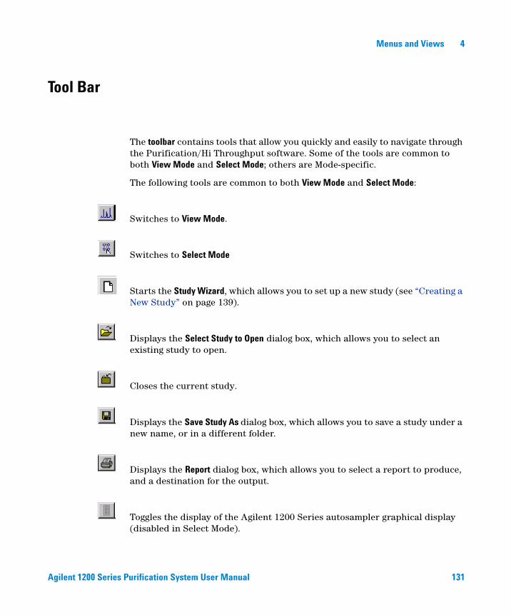
Agilent 1200 Series Purification System User Manual 131
Menus and Views 4
Tool Bar
The toolbar contains tools that allow you quickly and easily to navigate through the Purification/Hi Throughput software. Some of the tools are common to both View Mode and Select Mode; others are Mode-specific.
The following tools are common to both View Mode and Select Mode:
Switches to View Mode.
Switches to Select Mode
Starts the Study Wizard, which allows you to set up a new study (see “Creating a New Study” on page 139).
Displays the Select Study to Open dialog box, which allows you to select an existing study to open.
Closes the current study.
Displays the Save Study As dialog box, which allows you to save a study under a new name, or in a different folder.
Displays the Report dialog box, which allows you to select a report to produce, and a destination for the output.
Toggles the display of the Agilent 1200 Series autosampler graphical display (disabled in Select Mode).

132 Agilent 1200 Series Purification System User Manual
4 Menus and Views
Toggles the display of the Agilent 1200 Series fraction collector graphical display (disabled in Select Mode).
Toggles the display of a read-only version of the Study Parameters dialog box (disabled in Select Mode).
Allows you to toggle the display of the Study List (Samples) or the Study List (Injections) (disabled in Select Mode).
Toggles the display of the Results Panel containing the injection results.
In Select mode, this tool displays a snapshot of the current study.
Displays the Start Study dialog box, which allows you to run or reprocess a complete study or a partial study.
Pauses a running study at the end of the current run; this might be useful for adding or removing samples or fractions; to resume the study, press Start.
Stops a running study at the end of the current run; any remaining injections are not completed.
Aborts a study immediately; any remaining injections are not completed.
Displays the Purify Status panel, which shows the current status of the system.
Displays the Purification/Hi Throughput Software Help contents.
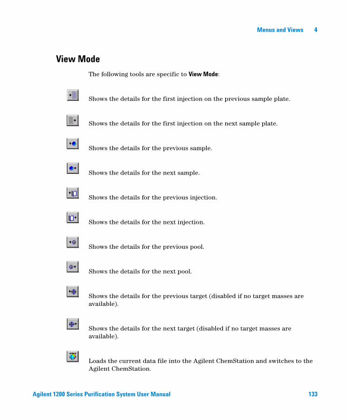
Agilent 1200 Series Purification System User Manual 133
Menus and Views 4
View Mode
The following tools are specific to View Mode:
Shows the details for the first injection on the previous sample plate.
Shows the details for the first injection on the next sample plate.
Shows the details for the previous sample.
Shows the details for the next sample.
Shows the details for the previous injection.
Shows the details for the next injection.
Shows the details for the previous pool.
Shows the details for the next pool.
Shows the details for the previous target (disabled if no target masses are available).
Shows the details for the next target (disabled if no target masses are available).
Loads the current data file into the Agilent ChemStation and switches to the Agilent ChemStation.

134 Agilent 1200 Series Purification System User Manual
4 Menus and Views
Select or Edit Mode
The following tools are specific to Select Mode:
Displays the Add Sample(s) dialog box, which allows you to specify one or more methods for the selected samples, and add the samples to the study.
Removes the selected samples from the study.
Displays the Modify Sample(s) dialog box, which allows you to modify the run parameters of the selected samples.
135
Agilent 1200 Series Purification SystemUser Manual
Agilent Technologies
5Study Setup
What is a Study? 136
Setting Up a New Study 138
Adding Samples to the Study List 147
Using CSV Files 158
Deleting Samples/ Injections from the Study List 163
Saving a Study 164
Deleting a Study 164
Opening a Study 165
Closing a Study 167
Modifying a Study 167
Setting Up a New Study Run 168
Setting Up a Partial Study 168
This chapter explains what a study is, and describes the process of setting up a study, including an explanation of all the necessary parameters.
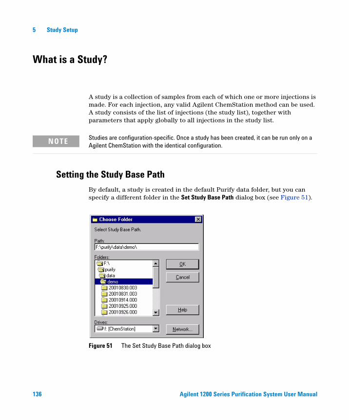
136 Agilent 1200 Series Purification System User Manual
5 Study Setup
What is a Study?
A study is a collection of samples from each of which one or more injections is made. For each injection, any valid Agilent ChemStation method can be used. A study consists of the list of injections (the study list), together with parameters that apply globally to all injections in the study list.
Setting the Study Base Path
By default, a study is created in the default Purify data folder, but you can specify a different folder in the Set Study Base Path dialog box (see Figure 51).
NOTE Studies are configuration-specific. Once a study has been created, it can be run only on a Agilent ChemStation with the identical configuration.
Figure 51 The Set Study Base Path dialog box
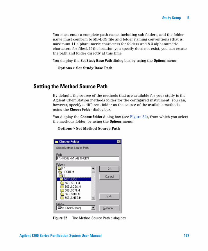
Agilent 1200 Series Purification System User Manual 137
Study Setup 5
You must enter a complete path name, including sub-folders, and the folder name must conform to MS-DOS file and folder naming conventions (that is, maximum 11 alphanumeric characters for folders and 8.3 alphanumeric characters for files). If the location you specify does not exist, you can create the path and folder directly at this time.
You display the Set Study Base Path dialog box by using the Options menu:
Options > Set Study Base Path
Setting the Method Source Path
By default, the source of the methods that are available for your study is the Agilent ChemStation methods folder for the configured instrument. You can, however, specify a different folder as the source of the available methods, using the Choose Folder dialog box.
You display the Choose Folder dialog box (see Figure 52), from which you select the methods folder, by using the Options menu:
Options > Set Method Source Path
Figure 52 The Method Source Path dialog box
138 Agilent 1200 Series Purification System User Manual
5 Study Setup
Setting Up a New Study
Studies are set up in the study editor; the study setup consists of three steps:
1 Creating the study
2 Setting up the study parameters
3 Specifying the report
4 Completing the Setup
You are guided through this process by the Study Wizard.
CAUTION Before you create a study, ensure that the sampler and fraction collector configurations in the Agilent ChemStation match the Agilent 1200 Series configurations (see “Instrument Parameters” on page 51); otherwise, you cannot use the study to acquire data.
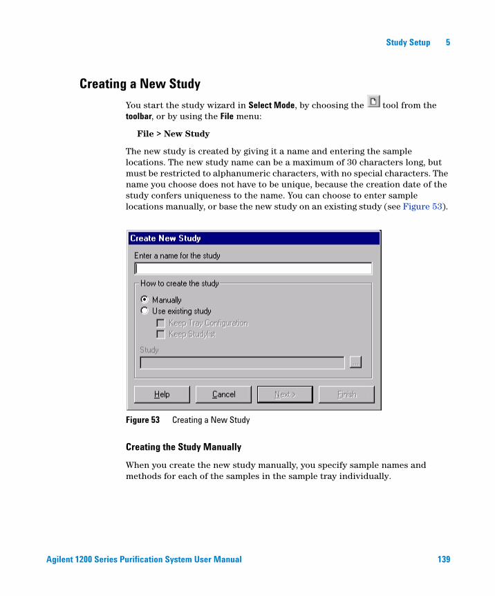
Agilent 1200 Series Purification System User Manual 139
Study Setup 5
Creating a New Study
You start the study wizard in Select Mode, by choosing the tool from the toolbar, or by using the File menu:
File > New Study
The new study is created by giving it a name and entering the sample locations. The new study name can be a maximum of 30 characters long, but must be restricted to alphanumeric characters, with no special characters. The name you choose does not have to be unique, because the creation date of the study confers uniqueness to the name. You can choose to enter sample locations manually, or base the new study on an existing study (see Figure 53).
Creating the Study Manually
When you create the new study manually, you specify sample names and methods for each of the samples in the sample tray individually.
Figure 53 Creating a New Study
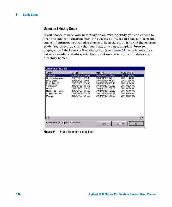
140 Agilent 1200 Series Purification System User Manual
5 Study Setup
Using an Existing Study
If you choose to base your new study on an existing study, you can choose to keep the tray configuration from the existing study. If you choose to keep the tray configuration, you can also choose to keep the study list from the existing study. You select the study that you want to use as a template; browse displays the Select Study to Open dialog box (see Figure 54), which contains a list of all available studies, with their creation and modification dates and directory names.
Figure 54 Study Selection dialog box
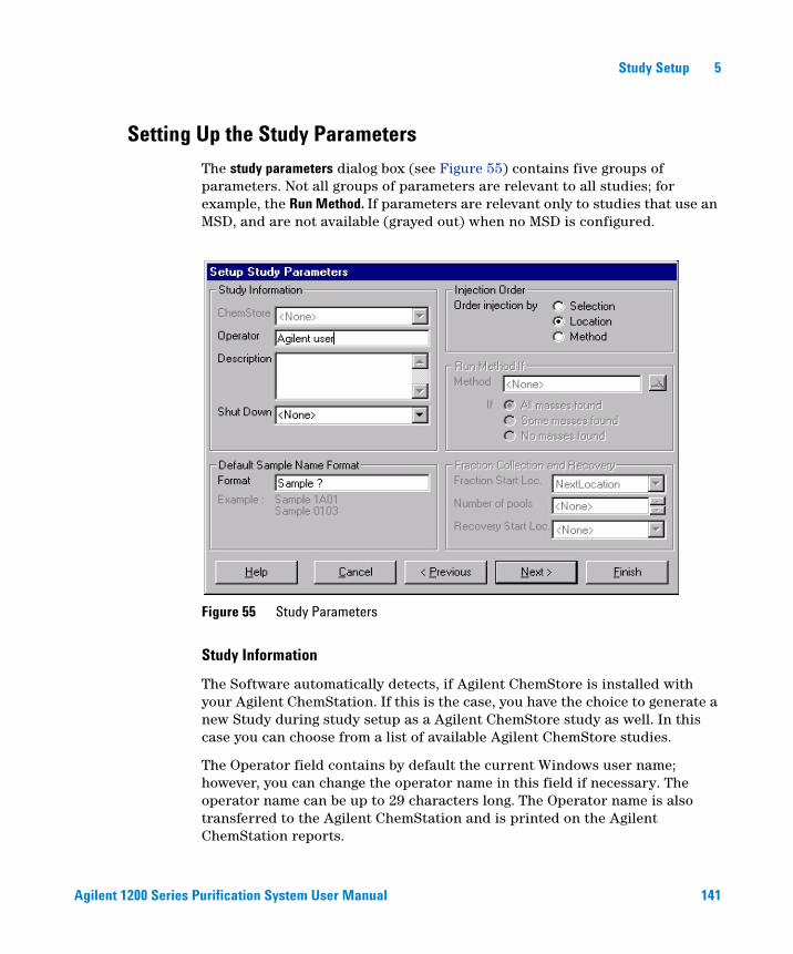
Agilent 1200 Series Purification System User Manual 141
Study Setup 5
Setting Up the Study Parameters
The study parameters dialog box (see Figure 55) contains five groups of parameters. Not all groups of parameters are relevant to all studies; for example, the Run Method. If parameters are relevant only to studies that use an MSD, and are not available (grayed out) when no MSD is configured.
Study Information
The Software automatically detects, if Agilent ChemStore is installed with your Agilent ChemStation. If this is the case, you have the choice to generate a new Study during study setup as a Agilent ChemStore study as well. In this case you can choose from a list of available Agilent ChemStore studies.
The Operator field contains by default the current Windows user name; however, you can change the operator name in this field if necessary. The operator name can be up to 29 characters long. The Operator name is also transferred to the Agilent ChemStation and is printed on the Agilent ChemStation reports.
Figure 55 Study Parameters
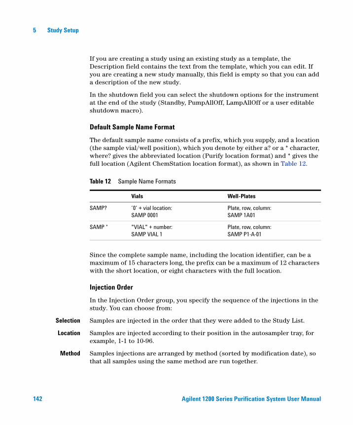
142 Agilent 1200 Series Purification System User Manual
5 Study Setup
If you are creating a study using an existing study as a template, the Description field contains the text from the template, which you can edit. If you are creating a new study manually, this field is empty so that you can add a description of the new study.
In the shutdown field you can select the shutdown options for the instrument at the end of the study (Standby, PumpAllOff, LampAllOff or a user editable shutdown macro).
Default Sample Name Format
The default sample name consists of a prefix, which you supply, and a location (the sample vial/well position), which you denote by either a? or a * character, where? gives the abbreviated location (Purify location format) and * gives the full location (Agilent ChemStation location format), as shown in Table 12.
Since the complete sample name, including the location identifier, can be a maximum of 15 characters long, the prefix can be a maximum of 12 characters with the short location, or eight characters with the full location.
Injection Order
In the Injection Order group, you specify the sequence of the injections in the study. You can choose from:
Selection Samples are injected in the order that they were added to the Study List.
Location Samples are injected according to their position in the autosampler tray, for example, 1-1 to 10-96.
Method Samples injections are arranged by method (sorted by modification date), so that all samples using the same method are run together.
Table 12 Sample Name Formats
Vials Well-Plates
SAMP? ’0’ + vial location: SAMP 0001
Plate, row, column: SAMP 1A01
SAMP * "VIAL" + number: SAMP VIAL 1
Plate, row, column: SAMP P1-A-01
Agilent 1200 Series Purification System User Manual 143
Study Setup 5
Fraction Collection and Recovery
In the Fraction Collection group, you specify the default start position in the fraction collector, and also specify the number of pools (the number of repetitions for fraction collection injections). If this dialog is greyed out, you don’t have a valid active fraction collector configuration available from your Agilent ChemStation.
Frac. StartLocation
You can choose one start location per study for the fraction collection in the study setup to start at the next available location on the current plate, at the first available location on the next plate (if more than one plate is configured), or at a specific location. When you add samples to a study, you can also specify individual fraction start locations for each sample.
In addition to the study start location for the fraction collection, it is possible to specify individual start locations for each sample (for more details, please refer to “Assigning the Fraction Start Position” on page 153).
Number of Pools You can specify the number of injections that are to be pooled (see Chapter 7, “Pooling”). You can pool up to 99 injections.
Recovery StartLocation
You can choose the recovery start location (see Chapter 5, “Recovery Locations”). This option is only available, if you have a valid configuration for Recovery.
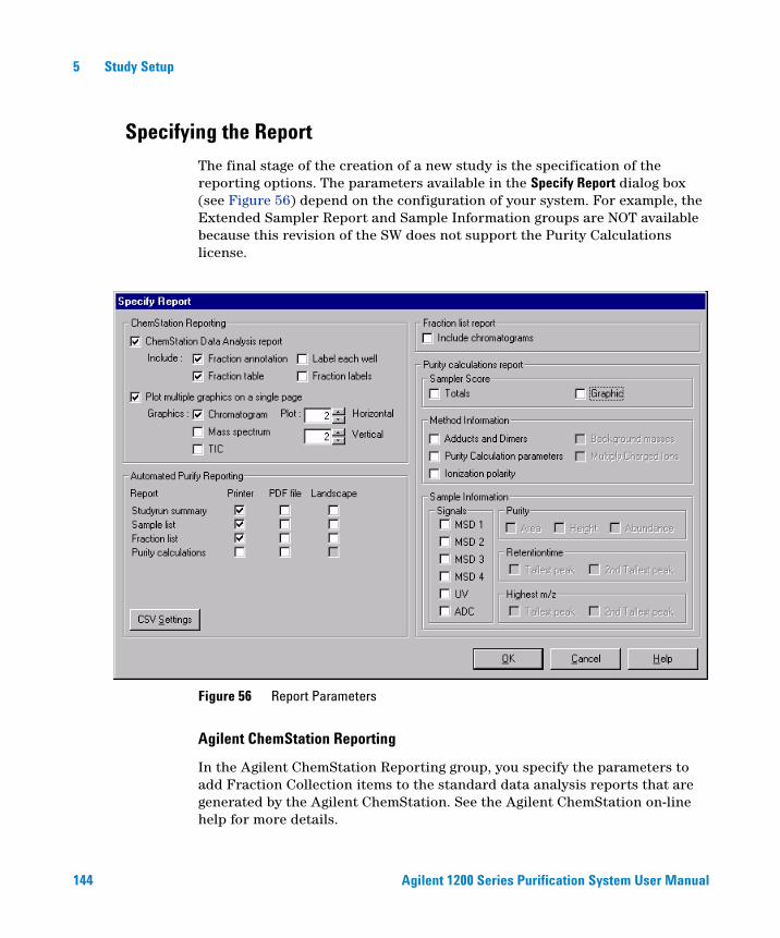
144 Agilent 1200 Series Purification System User Manual
5 Study Setup
Specifying the Report
The final stage of the creation of a new study is the specification of the reporting options. The parameters available in the Specify Report dialog box (see Figure 56) depend on the configuration of your system. For example, the Extended Sampler Report and Sample Information groups are NOT available because this revision of the SW does not support the Purity Calculations license.
Agilent ChemStation Reporting
In the Agilent ChemStation Reporting group, you specify the parameters to add Fraction Collection items to the standard data analysis reports that are generated by the Agilent ChemStation. See the Agilent ChemStation on-line help for more details.
Figure 56 Report Parameters
Agilent 1200 Series Purification System User Manual 145
Study Setup 5
Agilent ChemStation Data Analysis Report You mark this check box to specify that you want to produce the standard Agilent ChemStation reports at the end of the study run. When you mark this check box, you can also choose to include either annotation of the fractions on your chromatograms, or a printed fraction table (or both). If the fraction annotation option is selected, you also have the option to label each well or to add fraction labels. For details of the ChemStation reporting options, see “Agilent ChemStation Reporting” on page 202.
Plot Multiple Graphics on a Single Page You can print up to 81 graphics (nine columns × nine rows of chromatograms, mass spectra and/or TICs) on a single page. Such “thumbnail” graphics can be useful for a first visual review of the study data. You mark this check box to specify that you want to print multiple graphics, and mark the check boxes of the graphics you want to print in this way. You use the Plot fields to specify the number of rows and columns on each page.
Automated Purify Reporting
For the specific Purify reports, you can select the items to include, select either portrait (default) or landscape format, and select to produce the study results additionally as a PDF file and/or as a CSV (comma-separated values) file that you can import into a spreadsheet. You also specify the destination of the PDF and CSV files (default is the study folder) and select to overwrite existing files. For details of the Purify reporting options, see “Purification/Hi Throughput Reports” on page 205. The Export button allows you to export reports to CSV-files.
NOTE The Sampler Summary and Sampler Extended report functions are no longer available with revision A.02.01 or B.01.01 of the Purification/Hi Throughput software. The estimated purity calculation function has been incorporated into the LC/MSD ChemStation rev. A.10.01 or B.01.01 software, and the reporting of the estimated purity calculation results is now done using the G2727AA ChemStation Data Browser software. See the Online Help in Agilent ChemStation for more information on the estimated purity calculations.
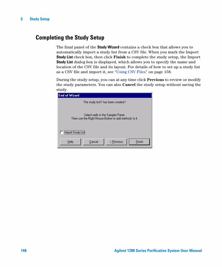
146 Agilent 1200 Series Purification System User Manual
5 Study Setup
Completing the Study Setup
The final panel of the Study Wizard contains a check box that allows you to automatically import a study list from a CSV file. When you mark the Import Study List check box, then click Finish to complete the study setup, the Import Study List dialog box is displayed, which allows you to specify the name and location of the CSV file and its layout. For details of how to set up a study list as a CSV file and import it, see “Using CSV Files” on page 158.
During the study setup, you can at any time click Previous to review or modify the study parameters. You can also Cancel the study setup without saving the study.
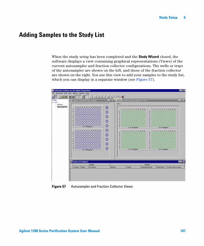
Agilent 1200 Series Purification System User Manual 147
Study Setup 5
Adding Samples to the Study List
When the study setup has been completed and the Study Wizard closed, the software displays a view containing graphical representations (Views) of the current autosampler and fraction collector configurations. The wells or trays of the autosampler are shown on the left, and those of the fraction collector are shown on the right. You use this view to add your samples to the study list, which you can display in a separate window (see Figure 57).
Figure 57 Autosampler and Fraction Collector Views

148 Agilent 1200 Series Purification System User Manual
5 Study Setup
Sampler Panel
You use the sampler panel to add samples to the study list. The following actions are possible in the sampler view:
Selecting Sample Locations
You can use the following mouse actions (separately or in combination) to select sample locations:
Single Location Click on the location with the left mouse button.
Complete Row orColumn
Click on the row or column label with the left mouse button.
RectangularSection
Draw a rectangle around the required locations.
Deselecting Sample Locations
Clicking on a selected sample location with the left mouse button toggles the location selection.
Location Selection Indicators
Table 13 explains the color indicators used to show the state of each location in the Sampler panel:
Table 13 Sample Location Indicators
Line Color Fill Color Meaning
Blue Gray The location has not been selected, or has been deselected.
White Gray The location has been selected but not yet added to the study list.
Blue Dark blue The location has been added to the study list.
White Dark blue The location has been added to the study list and has been selected (for example, for modifying).
Blue Light blue The location has been added to a partial study.
White Light blue The location has been added to a partial study and has been selected (for example, for modifying).
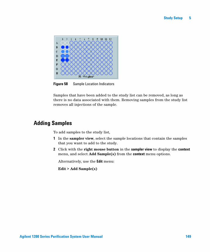
Agilent 1200 Series Purification System User Manual 149
Study Setup 5
Samples that have been added to the study list can be removed, as long as there is no data associated with them. Removing samples from the study list removes all injections of the sample.
Adding Samples
To add samples to the study list,
1 In the sampler view, select the sample locations that contain the samples that you want to add to the study.
2 Click with the right mouse button in the sampler view to display the context menu, and select Add Sample(s) from the context menu options.
Alternatively, use the Edit menu:
Edit > Add Sample(s)
Figure 58 Sample Location Indicators
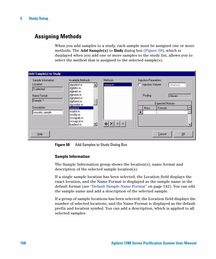
150 Agilent 1200 Series Purification System User Manual
5 Study Setup
Assigning Methods
When you add samples to a study, each sample must be assigned one or more methods. The Add Sample(s) to Study dialog box (Figure 59), which is displayed when you add one or more samples to the study list, allows you to select the method that is assigned to the selected sample(s).
Sample Information
The Sample Information group shows the location(s), name format and description of the selected sample location(s).
If a single sample location has been selected, the Location field displays the exact location, and the Name Format is displayed as the sample name in the default format (see “Default Sample Name Format” on page 142). You can edit the sample name and add a description of the selected sample.
If a group of sample locations has been selected, the Location field displays the number of selected locations, and the Name Format is displayed as the default prefix and location symbol. You can add a description, which is applied to all selected samples.
Figure 59 Add Samples to Study Dialog Box

Agilent 1200 Series Purification System User Manual 151
Study Setup 5
Available Methods
The Available Methods panel displays a list of all the methods in the Method Source (by default, the Agilent ChemStation Methods folder). You select one or more methods to apply to the selected samples from this list, and use the + tool to transfer it to the Methods panel.
If you want to make multiple injections of the same sample location without pooling (see Chapter 7, “Pooling”), you specify the same method multiple times.
Methods
The Methods panel shows the method(s) that will be applied to the selected samples. The methods will be applied in the listed sequence; you can change the sequence using the up and down arrows, or remove a method from the list using the [X] tool.
Injection Parameters
In the injection parameters group, you specify the injection volume for each method (if different from the method parameters). The Injection Parameters group also displays the number of pools specified.
Run Method If
The Run Method If group (for LC-MSD, only) allows you to reinject and rerun a sample using a second Agilent ChemStation method if certain conditions related to the purity of the sample are met. The conditions are:
• All the target masses are found
• Some (at least one but not all) target masses are found
• None of the target masses are found
A target mass is ’’found’’ if the purity calculation for that target mass exceeds the qualifier level as specified in the Edit Method panel.
Expected masses
The masses to expect can be filled in using their absolute mass or using their molecular formula. The masses are used for mass based fraction.
152 Agilent 1200 Series Purification System User Manual
5 Study Setup
Modifying Samples
You can modify the samples in the study, for example to associate additional methods, change injection parameters, or change the sample name or description. For LC/MS systems, you can also change the expected masses. However, if you are modifying a sample for reprocessing, you can change only the sample name and description.
To modify a sample,
1 If necessary, click the tool to switch to Select mode.
2 In the sampler view, select the sample location that contains the sample that you want to modify.
3 Click with the right mouse button in the sampler view to display the context menu, and select Modify Sample from the context menu options. Samples can also be modified directly in the sample list.
Alternatively, use the Edit menu:
Edit > Modify Sample.
The Modify Sample dialog box that is displayed has the same configuration at the Add Samples to Study dialog box (see Figure 59 on page 150). Parameters that are available for modification are active; parameters that are fixed are inactive (grayed).

Agilent 1200 Series Purification System User Manual 153
Study Setup 5
Fraction Collector Panel
You use the fraction collector panel to assign fraction start position and recovery locations (see “Recovery Locations” on page 156). The following actions are possible in the fraction collector view:
Assigning the Fraction Start Position
You assign the fraction start position from the context menu of the sampler and the fraction collector panel. You can select any valid position on the fraction collector tray (that is, any position that is not a recovery location or a reserved location, or that has not already been used for fraction collection on this tray).
Select the sample(s) that should be modified with a mouse click on the sampler panel (the selected sample(s) will be displayed with a white circle in the sampler panel).
Start Fraction atNext Location
To display the context menu, click the right mouse button in the sampler panel. If you choose Next Location this will start the fraction collection at the next available location for the currently selected sample(s).
Start Fraction at<SelectedLocation>
To display the context menu, click the right mouse button in the fraction collector panel. If you choose Selected Location this will start the fraction collection at the selected location for the currently selected sample(s), for example, 1-P2-A03 starts fraction collection at location A03 on the second plate of the first fraction collector.
CAUTION If you remove and replace the tray, the information about locations that have already been used for fraction collection are reset / lost.

154 Agilent 1200 Series Purification System User Manual
5 Study Setup
Location Indicators
Table 14 explains the color indicators used to show the state of each location in the Fraction Collector panel:
Table 14 Fraction Collector Location Indicators
Line Color Fill Color Meaning
Green Gray The location has not been assigned, or has been unassigned.
White Gray The location has been selected.
Green Green The location has been assigned.
White Green The location has been assigned and selected.
Dark green Gray The location can be used as a recovery location (see “Recovery Locations” on page 156).
Dark green Dark green The location has been assigned as a recovery location.
White Dark green The location has been assigned as a recovery location and selected.
Gray Gray The location cannot be used for fraction collection, either because of the tray type, or because the location has been specified as a reserved location in the fraction collector configuration (see “Configuration” on page 67).
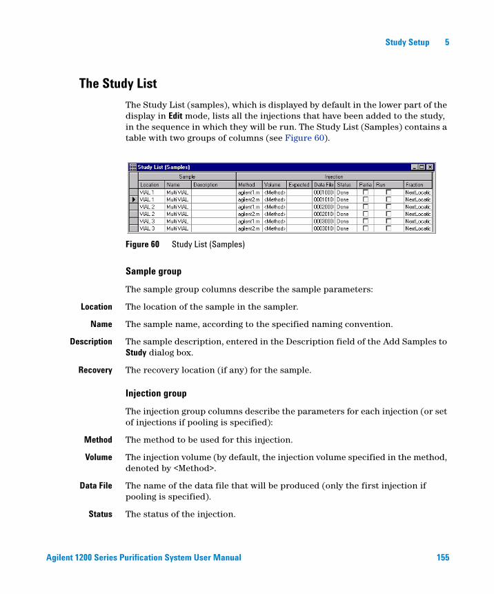
Agilent 1200 Series Purification System User Manual 155
Study Setup 5
The Study List
The Study List (samples), which is displayed by default in the lower part of the display in Edit mode, lists all the injections that have been added to the study, in the sequence in which they will be run. The Study List (Samples) contains a table with two groups of columns (see Figure 60).
Sample group
The sample group columns describe the sample parameters:
Location The location of the sample in the sampler.
Name The sample name, according to the specified naming convention.
Description The sample description, entered in the Description field of the Add Samples to Study dialog box.
Recovery The recovery location (if any) for the sample.
Injection group
The injection group columns describe the parameters for each injection (or set of injections if pooling is specified):
Method The method to be used for this injection.
Volume The injection volume (by default, the injection volume specified in the method, denoted by <Method>.
Data File The name of the data file that will be produced (only the first injection if pooling is specified).
Status The status of the injection.
Figure 60 Study List (Samples)

156 Agilent 1200 Series Purification System User Manual
5 Study Setup
Partial Study Checked if the sample is specified for a partial study.
Recovery Locations
You use recovery locations to collect the baseline eluent (between fractions) into a separate funnel (see Figure 61).
You can collect the baseline between fractions into funnels, if a funnel tray is installed in the fraction collector, into vials, if in your fraction collector a vial tray is installed in addition to wellplate trays or if your system has a dedicated recovery fraction collector. Using the recovery option should be applied in case the separation and the fraction collection regimes become un-coordinated. Baseline recovery also helps to avoid the consequences of operator error, for example leading to a peak of interest in a rare sample being missed.
Recovery locations are set up as part of the study setup with the study setup wizard. This option is only active, if your system has a configuration valid for the use with the recovery option (see below).
The following properties apply to recovery locations:
Figure 61 Recovering baseline eluent in a recovery location

Agilent 1200 Series Purification System User Manual 157
Study Setup 5
• Recovery locations are available only when either:- one fraction collector with a funnel tray is configured or - you can recover into vials, if in your fraction collector a vial tray is installed in addition to a wellplate tray or - if your system has a dedicated recovery fraction collector.
• Only one recovery start location can be allocated per study run, and one individual recovery location will then be used for every sample in thus study run.
• The non-fraction collected portion of all injections of the sample flows into the specified recovery location.
• If no recovery location is specified, the non-fraction collected portion is directed to waste.
• You cannot use a recovery location for fraction collection.
Assigning Recovery Locations
You assign recovery locations in the study setup wizard during the generation of a study. The recovery location is then denoted as a filled dark green circle in the fraction collector panel.
Recovery locations can also be setup interactively in the fraction collector panel (left mouse click to select a location and then right mouse click on this selected location to bring up a menu, that allows to toggles between a fixed position as a start location and the next available (free) position.
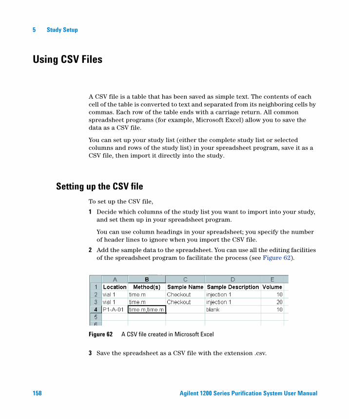
158 Agilent 1200 Series Purification System User Manual
5 Study Setup
Using CSV Files
A CSV file is a table that has been saved as simple text. The contents of each cell of the table is converted to text and separated from its neighboring cells by commas. Each row of the table ends with a carriage return. All common spreadsheet programs (for example, Microsoft Excel) allow you to save the data as a CSV file.
You can set up your study list (either the complete study list or selected columns and rows of the study list) in your spreadsheet program, save it as a CSV file, then import it directly into the study.
Setting up the CSV file
To set up the CSV file,
1 Decide which columns of the study list you want to import into your study, and set them up in your spreadsheet program.
You can use column headings in your spreadsheet; you specify the number of header lines to ignore when you import the CSV file.
2 Add the sample data to the spreadsheet. You can use all the editing facilities of the spreadsheet program to facilitate the process (see Figure 62).
3 Save the spreadsheet as a CSV file with the extension .csv.
Figure 62 A CSV file created in Microsoft Excel

Agilent 1200 Series Purification System User Manual 159
Study Setup 5
Importing the CSV file
To import a Study List from a CSV file,
1 Open the Import Study List dialog box using the File menu:
File > Import Study List...
The Import Study List dialog box is shown in Figure 65.
2 Click the button at the right of the CSV File field to display the file selection dialog box, and select the CSV file you want to import.
3 Set up the Fields in CSV File list to be identical with the columns in your CSV file (in the correct sequence).
Click [<] to transfer the selected item from the right panel to the left panel, and [>] to transfer the selected item from the left panel to the right panel.
4 If you have set up your spreadsheet with column headings, specify the number of header lines to skip.
You can either edit the field directly or use the up and down arrows to increase or decrease the number of rows.
Figure 63 Import Study List dialog box
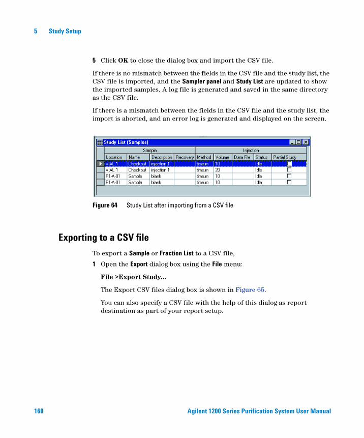
160 Agilent 1200 Series Purification System User Manual
5 Study Setup
5 Click OK to close the dialog box and import the CSV file.
If there is no mismatch between the fields in the CSV file and the study list, the CSV file is imported, and the Sampler panel and Study List are updated to show the imported samples. A log file is generated and saved in the same directory as the CSV file.
If there is a mismatch between the fields in the CSV file and the study list, the import is aborted, and an error log is generated and displayed on the screen.
Exporting to a CSV file
To export a Sample or Fraction List to a CSV file,
1 Open the Export dialog box using the File menu:
File >Export Study...
The Export CSV files dialog box is shown in Figure 65.
You can also specify a CSV file with the help of this dialog as report destination as part of your report setup.
Figure 64 Study List after importing from a CSV file
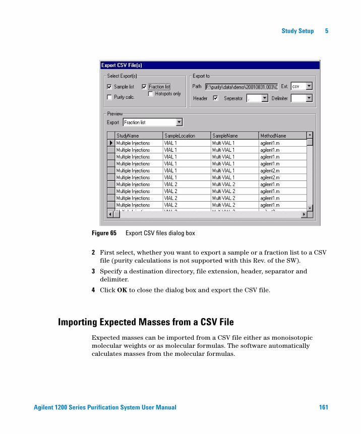
Agilent 1200 Series Purification System User Manual 161
Study Setup 5
2 First select, whether you want to export a sample or a fraction list to a CSV file (purity calculations is not supported with this Rev. of the SW).
3 Specify a destination directory, file extension, header, separator and delimiter.
4 Click OK to close the dialog box and export the CSV file.
Importing Expected Masses from a CSV File
Expected masses can be imported from a CSV file either as monoisotopic molecular weights or as molecular formulas. The software automatically calculates masses from the molecular formulas.
Figure 65 Export CSV files dialog box
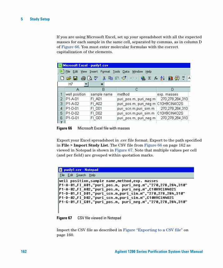
162 Agilent 1200 Series Purification System User Manual
5 Study Setup
If you are using Microsoft Excel, set up your spreadsheet with all the expected masses for each sample in the same cell, separated by commas, as in column D of Figure 66. You must enter molecular formulas with the correct capitalization of the elements.
Export your Excel spreadsheet in .csv file format. Export to the path specified in File > Import Study List. The CSV file from Figure 66 on page 162 as viewed in Notepad is shown in Figure 67. Note that multiple values per cell (and per field) are grouped within quotation marks.
Import the CSV file as described in Figure “Exporting to a CSV file” on page 160.
am
Figure 66 Microsoft Excel file with masses
Figure 67 CSV file viewed in Notepad
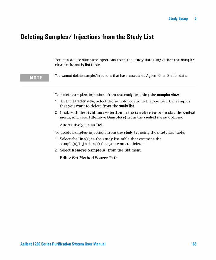
Agilent 1200 Series Purification System User Manual 163
Study Setup 5
Deleting Samples/ Injections from the Study List
You can delete samples/injections from the study list using either the sampler view or the study list table.
To delete samples/injections from the study list using the sampler view,
1 In the sampler view, select the sample locations that contain the samples that you want to delete from the study list.
2 Click with the right mouse button in the sampler view to display the context menu, and select Remove Sample(s) from the context menu options.
Alternatively, press Del.
To delete samples/injections from the study list using the study list table,
1 Select the line(s) in the study list table that contains the sample(s)/injection(s) that you want to delete.
2 Select Remove Sample(s) from the Edit menu
Edit > Set Method Source Path
NOTE You cannot delete sample/injections that have associated Agilent ChemStation data.

164 Agilent 1200 Series Purification System User Manual
5 Study Setup
Saving a Study
Studies are saved automatically when any changes are made. The changes you make cannot be canceled or undone. You can save a copy of a study with a different name so that you can make changes without modifying the original study parameters.
You save a study by choosing the tool from the toolbar, or by using the File menu:
File > Save Study As
You type the name (and, if necessary, a new path) for the copy of the study in the Save Study As dialog box.
Deleting a Study
Once a study has been created, it cannot be deleted from within the Purification/Hi Throughput software.
Agilent 1200 Series Purification System User Manual 165
Study Setup 5
Opening a Study
You open a study by choosing the tool from the toolbar, or by using the File menu:
File > Open Study
The Select Study to Open dialog box that is displayed (see Figure 54 on page 140) contains a tabular list of all available studies in the current study base path.
The list contains all studies in the base path, irrespective of their compatibility with the current Agilent ChemStation configuration. The table contains four columns:
Study The name of the study.
Created The date and time of creation of the study.
Modified The date and time of the last modification to the study.
Study directory The folder in which the study data and methods are stored.
You can select one study to open from the list; any study that is currently open is closed before the selected study is opened. Previous studies that have been opened in the current session (since the Purification/Hi Throughput software was started) are listed in the explorer at the left of the display.
NOTE You cannot open a study that has been write-protected.
166 Agilent 1200 Series Purification System User Manual
5 Study Setup
On-line Agilent ChemStation
To run a study, its configuration must match the current Agilent ChemStation configuration absolutely. If the configuration of the study you open is compatible with the current Agilent ChemStation configuration, you can acquire, view and reprocess data. However, if there is any mismatch between the study configuration and the current Agilent ChemStation configuration, the study will not run. In the case of a mismatch of configurations, you can view and reprocess data, but you cannot acquire data.
Off-line Agilent ChemStation
Compatibility of study and Agilent ChemStation configurations is unnecessary in the case of off-line operation. In off-line mode, you can view and reprocess data, but you cannot acquire data.
Agilent 1200 Series Purification System User Manual 167
Study Setup 5
Closing a Study
You choosing the tool from the toolbar, or use the File menu to close a study that you have selected in the explorer at the left of the display:
File > Close Study
Modifying a Study
You can modify a study in either on-line or off-line mode. If the study has no data, you can modify the study parameters, the study list and the reporting parameters. If the study already contains data, you can modify the study list (to add or remove samples/injections) and the reporting parameters only.
NOTE You cannot close a study that is currently running (acquiring data).
NOTE You cannot make modifications to a study that is running unless you “Pause” the study before doing so.
168 Agilent 1200 Series Purification System User Manual
5 Study Setup
Setting Up a New Study Run
You can set up a new study run within an existing study; the new study run has the name Study Run <n>, where <n> is incremented for each new study run. The new study run opens with an empty study list. You can configure the new study run to contain some or all of the samples in the existing study, and you can add new samples in exactly the same way as when you set up a new study. You can also add or remove methods from the study, including the methods associated with the existing samples. You can also modify the study parameters and the reporting parameters for the new study run.
To set up a new study run,
1 If necessary, open the study from you want to set up a new study run (see “Opening a Study” on page 165).
2 In the study tree, select the study run from you want to set up the new study run.
3 Switch to Edit mode and select the samples that you want to include in the new study run.
4 Open the context menu for the Sampler panel (right mouse click) and select Add Sample(s) to New StudyRun.
5 If you want to add more samples to the new study run, or modify the samples you have added, select New Study Run from the study tree and make the necessary modifications.
Setting Up a Partial Study
You may want to run only a selection of the samples in the study list if, for example, you have imported the study list but do not have a complete set of samples, or if you want to reprocess a group of samples with modified method parameters. You set the partial study up in Edit mode.
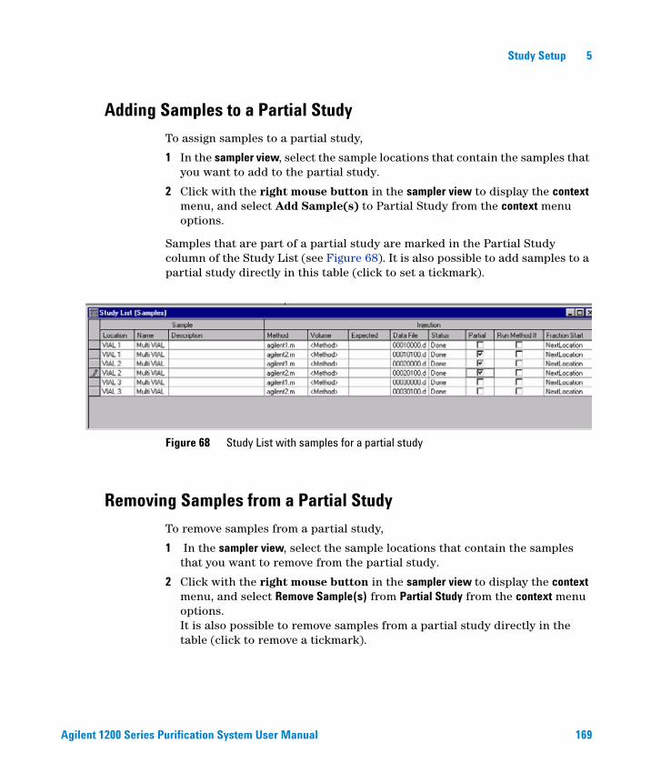
Agilent 1200 Series Purification System User Manual 169
Study Setup 5
Adding Samples to a Partial Study
To assign samples to a partial study,
1 In the sampler view, select the sample locations that contain the samples that you want to add to the partial study.
2 Click with the right mouse button in the sampler view to display the context menu, and select Add Sample(s) to Partial Study from the context menu options.
Samples that are part of a partial study are marked in the Partial Study column of the Study List (see Figure 68). It is also possible to add samples to a partial study directly in this table (click to set a tickmark).
Removing Samples from a Partial Study
To remove samples from a partial study,
1 In the sampler view, select the sample locations that contain the samples that you want to remove from the partial study.
2 Click with the right mouse button in the sampler view to display the context menu, and select Remove Sample(s) from Partial Study from the context menu options.It is also possible to remove samples from a partial study directly in the table (click to remove a tickmark).
Figure 68 Study List with samples for a partial study
170 Agilent 1200 Series Purification System User Manual
5 Study Setup
171
Agilent 1200 Series Purification SystemUser Manual
Agilent Technologies
6Running Studies
Run Control 172
Study Status 174
Online Tickmarks 175
Reprocessing Studies 176
This chapter describes the options for running and reprocessing studies.
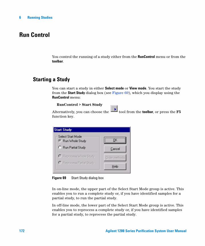
172 Agilent 1200 Series Purification System User Manual
6 Running Studies
Run Control
You control the running of a study either from the RunControl menu or from the toolbar.
Starting a Study
You can start a study in either Select mode or View mode. You start the study from the Start Study dialog box (see Figure 69), which you display using the RunControl menu:
RunControl > Start Study
Alternatively, you can choose the tool from the toolbar, or press the F5 function key.
In on-line mode, the upper part of the Select Start Mode group is active. This enables you to run a complete study or, if you have identified samples for a partial study, to run the partial study.
In off-line mode, the lower part of the Select Start Mode group is active. This enables you to reprocess a complete study or, if you have identified samples for a partial study, to reprocess the partial study.
Figure 69 Start Study dialog box

Agilent 1200 Series Purification System User Manual 173
Running Studies 6
Stopping a Study
You can stop a study that is running either by choosing the tool from the toolbar, or by using the RunControl menu:
RunControl > Stop Study
The study stops at the end of the current run; any remaining injections are not completed.
Pausing a Study
You can pause a study that is running either by choosing the tool from the toolbar, or by using the RunControl menu:
RunControl > Pause
The study is paused and you can add samples or modify the current study; to resume the study press the start study button.
Aborting a Study
You can abort a study that is running either by choosing the tool from the toolbar, or by using the RunControl menu:
RunControl > Abort
The study stops immediately; any remaining injections are not completed.
Study Stop / Abort Criteria
The study stops when the study has no injections left that have no data associated and you have stopped the study .
The study is aborted when you abort the study or the Agilent ChemStation is aborted, either automatically (for example, because of a leak) or through user intervention.
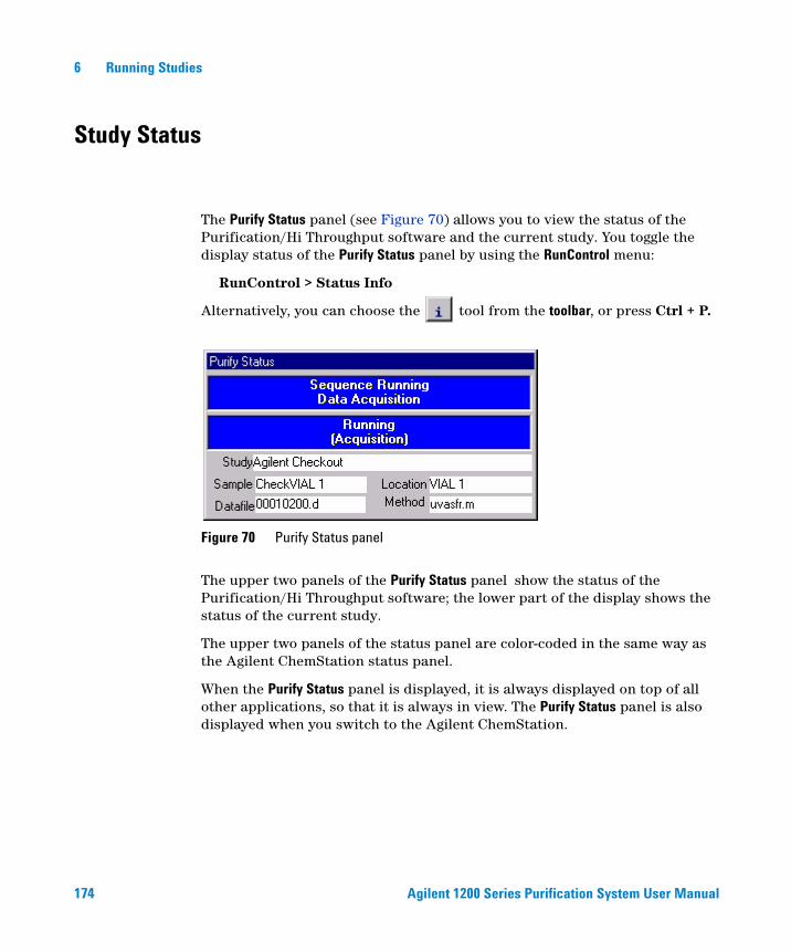
174 Agilent 1200 Series Purification System User Manual
6 Running Studies
Study Status
The Purify Status panel (see Figure 70) allows you to view the status of the Purification/Hi Throughput software and the current study. You toggle the display status of the Purify Status panel by using the RunControl menu:
RunControl > Status Info
Alternatively, you can choose the tool from the toolbar, or press Ctrl + P.
The upper two panels of the Purify Status panel show the status of the Purification/Hi Throughput software; the lower part of the display shows the status of the current study.
The upper two panels of the status panel are color-coded in the same way as the Agilent ChemStation status panel.
When the Purify Status panel is displayed, it is always displayed on top of all other applications, so that it is always in view. The Purify Status panel is also displayed when you switch to the Agilent ChemStation.
Figure 70 Purify Status panel

Agilent 1200 Series Purification System User Manual 175
Running Studies 6
Online Tickmarks
You can view the results of the current study run Online while the fractions are being collected. Open the Online Plot in the Agilent ChemStations Method&Run Control View and select to display tickmarks for the Online chromatogram as shown in Figure 71.
Figure 71 An example of an Online plot with tickmarks
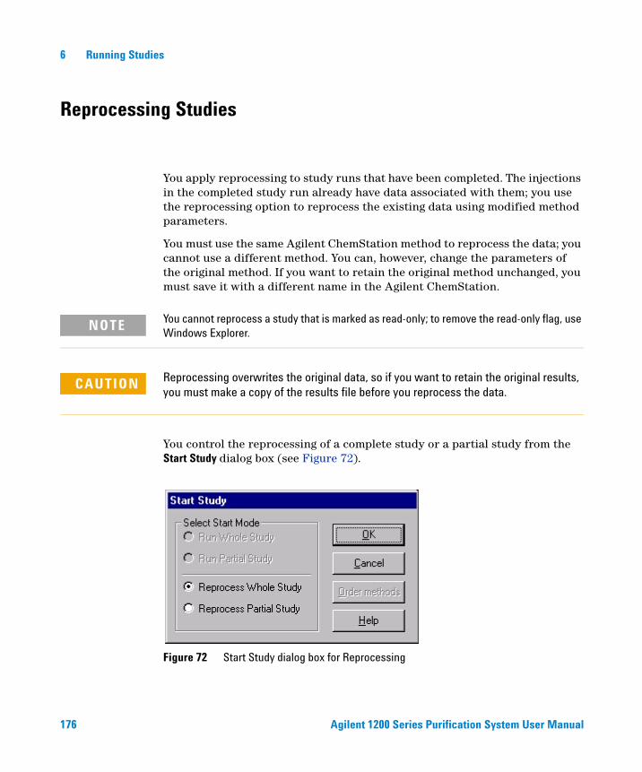
176 Agilent 1200 Series Purification System User Manual
6 Running Studies
Reprocessing Studies
You apply reprocessing to study runs that have been completed. The injections in the completed study run already have data associated with them; you use the reprocessing option to reprocess the existing data using modified method parameters.
You must use the same Agilent ChemStation method to reprocess the data; you cannot use a different method. You can, however, change the parameters of the original method. If you want to retain the original method unchanged, you must save it with a different name in the Agilent ChemStation.
You control the reprocessing of a complete study or a partial study from the Start Study dialog box (see Figure 72).
NOTE You cannot reprocess a study that is marked as read-only; to remove the read-only flag, use Windows Explorer.
CAUTION Reprocessing overwrites the original data, so if you want to retain the original results, you must make a copy of the results file before you reprocess the data.
Figure 72 Start Study dialog box for Reprocessing
Agilent 1200 Series Purification System User Manual 177
Running Studies 6
The commands for reprocessing studies are identical to those for running a study. However, you can reprocess a study in both on-line and off-line versions of the Agilent ChemStation and the Purification/Hi Throughput software.
Resetting the Vessel Fill Volumes
You can reset the actual fill level of the vessels in your tray by removing the tray from the fraction collector and re-inserting it. By doing so the instrument will assume, that all positions in the re-inserted tray are empty

178 Agilent 1200 Series Purification System User Manual
6 Running Studies
179
Agilent 1200 Series Purification SystemUser Manual
Agilent Technologies
7Pooling
What is Pooling? 180
Pooling Properties 182
Setting Up a Study for Pooling 182
This chapter explains the concept of pooling, and describes how to set up a pooling run.
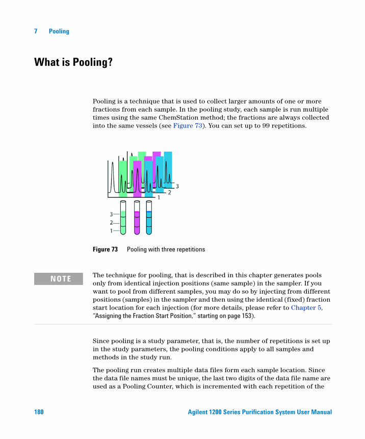
180 Agilent 1200 Series Purification System User Manual
7 Pooling
What is Pooling?
Pooling is a technique that is used to collect larger amounts of one or more fractions from each sample. In the pooling study, each sample is run multiple times using the same ChemStation method; the fractions are always collected into the same vessels (see Figure 73). You can set up to 99 repetitions.
Since pooling is a study parameter, that is, the number of repetitions is set up in the study parameters, the pooling conditions apply to all samples and methods in the study run.
The pooling run creates multiple data files form each sample location. Since the data file names must be unique, the last two digits of the data file name are used as a Pooling Counter, which is incremented with each repetition of the
Figure 73 Pooling with three repetitions
NOTE The technique for pooling, that is described in this chapter generates pools only from identical injection positions (same sample) in the sampler. If you want to pool from different samples, you may do so by injecting from different positions (samples) in the sampler and then using the identical (fixed) fraction start location for each injection (for more details, please refer to Chapter 5, “Assigning the Fraction Start Position,” starting on page 153).

Agilent 1200 Series Purification System User Manual 181
Pooling 7
sample injection (see Chapter 10, “Directory Structure and File Naming”). Figure 74 shows a Study List (Injections) for a run with three samples, each pooled three times. Note the data file naming, in which the fourth character denotes the injection number and the final character denotes the pool number.
Figure 74 Study List (Injections) with pooled samples
CAUTION Since pooling always collects the same fraction into the same container, you must set up the pooling parameters (for example, the number of pools) to ensure that the containers you have configured are not over-filled.

182 Agilent 1200 Series Purification System User Manual
7 Pooling
Pooling Properties
The following properties apply to the pooling facility of the Purification/Hi Throughput software:
• One sample can be pooled up to 99 times. This is a restriction imposed by the data file naming conventions of the sequence engine.
• An injection marked for pooling is repeated consecutively as specified in the pooling parameters.
• Pooling applies to all injections/samples in the study or partial study that have a fraction collection method.
• If the study list contains a mixture of fraction collection methods and non-fraction collection methods, the fraction collection methods are pooled, and the non-fraction collection methods are run as single injections.
• You can specify pooling for each study run individually, including the number of repetitions. To track pooled injections, the repetition number is stored as an extension to the file name with the injection information in the study database.
Setting Up a Study for Pooling
You set up the number of repetitions of each sample in the Fraction Collection group of the Setup Study Parameters dialog box (see “Setting Up the Study Parameters” on page 141). You can pool between 2 and 99 injections.
Figure 75 Pooling set up in the Study Parameters dialog box
183
Agilent 1200 Series Purification SystemUser Manual
Agilent Technologies
8Data Review
Overview 184
Data View Panels 185
This chapter describes the options available in the software for reviewing the study data.

184 Agilent 1200 Series Purification System User Manual
8 Data Review
Overview
You can review any open study (see “Opening a Study” on page 165) either as a stand-alone task, or as a background task while another study is running. You can select the results to review in several ways:
• selecting a location from the Sampler panel,
• selecting a fraction from the Fraction Collector panel
• selecting a sample from one of the Study Lists
No matter which way you select the sample, all panels are updated to mark the selected sample and its fractions.
Agilent 1200 Series Purification System User Manual 185
Data Review 8
Data View Panels
The data view panels that are displayed in View mode are selectable, either using the toolbar or using the items of the View menu. Six panels are available:
• Study Parameters
• Sampler
• Fraction Collector
• Study List (Samples)
• Study List (Injections)
• Result
The panels are interactive, so that when you select a sample in the Sampler panel, it is also selected in both study lists, and when you select a sample in one of the study lists, it is also highlighted on the Sampler panel. The fractions for the selected sample or injection are displayed simultaneously in the Study List (Injections) and the Result panel.
Study Parameters
The study parameters panel is a read-only version of the Setup Study Parameters panel (see Figure 55 on page 141). It shows the parameters that were set up when the study was created.
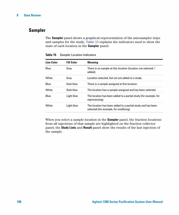
186 Agilent 1200 Series Purification System User Manual
8 Data Review
Sampler
The Sampler panel shows a graphical representation of the autosampler trays and samples for the study. Table 15 explains the indicators used to show the state of each location in the Sampler panel:
When you select a sample location in the Sampler panel, the fraction locations from all injections of that sample are highlighted on the fraction collector panel; the Study Lists and Result panel show the results of the last injection of the sample.
Table 15 Sampler Location Indicators
Line Color Fill Color Meaning
Blue Gray There is no sample at this location (location not selected / added).
White Gray Location selected, but not yet added to a study.
Blue Dark blue There is a sample assigned at this location.
White Dark blue The location has a sample assigned and has been selected.
Blue Light blue The location has been added to a partial study (for example, for reprocessing).
White Light blue The location has been added to a partial study and has been selected (for example, for modifying).
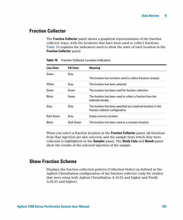
Agilent 1200 Series Purification System User Manual 187
Data Review 8
Fraction Collector
The Fraction Collector panel shows a graphical representation of the fraction collector trays, with the locations that have been used to collect fractions. Table 16 explains the indicators used to show the state of each location in the Fraction Collector panel:
When you select a fraction location in the Fraction Collector panel, all fractions from that injection are also selected, and the sample from which they were collected is highlighted on the Sampler panel. The Study Lists and Result panel show the results of the selected injection of the sample.
Show Fraction Scheme
Displays the fraction collection pattern (Collection Order) as defined in the Agilent ChemStation configuration of the fraction collector (only for studies that were setup with Agilent ChemStation A.10.01 and higher and Purify A.02.01 and higher).
Table 16 Fraction Collector Location Indicators
Line Color Fill Color Meaning
Green GrayThe location has not been used to collect fractions (empty).
White Gray The location has been selected.
Green Green The location has been used for fraction collection.
Black Green The location has been used to collect a fraction from the selected sample.
Gray Gray The location has been specified as a reserved location in the fraction collector configuration.
Dark Green Grey Empty recovery location
Black Dark Green The location has been used as a recovery location.
188 Agilent 1200 Series Purification System User Manual
8 Data Review
Study Parameters
Displays the study poarameters as defined during the study setup.
Study List (Samples)
The Study List (Samples) in View mode is identical with the Study List (Samples) displayed in Edit mode (see “The Study List” on page 155). The selected sample is denoted by an arrow in the left column of the table.
The Injection group columns describe the parameters for each injection:
The selected injection is denoted by an arrow in the left column of the table.
Location The location of the sample in the sampler.
Name The sample name, according to the specified naming convention.
Description The sample description, entered in the Description field of the Add Samples to Study dialog box.
Method The method used for this injection.
Volume The injection volume (by default, the injection volume specified in the method, denoted by <Method>).
Data File The name of the data file that will be produced (only the first injection if pooling is specified).
Recovery The recovery location for this injection.
Recovery Vol. The volume of sample recovered.
Status Sample status.
Partial Selected if this sample is part of a partial study.
Fraction Start Fraction Start position for this sample.
Agilent 1200 Series Purification System User Manual 189
Data Review 8
Study List (Injections)
The Study List (Injections), which is available only in View Mode after the study has been run, contains two tables. The upper table lists all the samples that have been run, in the sequence that they were run; the lower table lists all fractions that were collected for a selected injection.
Table of Injections
The table of samples contains two groups of columns:
The Sample group columns describe the sample parameters:
The Injection group columns describe the parameters for each injection:
The selected injection is denoted by an arrow in the left column of the table.
Location The location of the sample in the sampler.
Name The sample name, according to the specified naming convention.
Description The sample description, entered in the Description field of the Add Samples to Study dialog box.
Injection No. The injection number for this sample.
Pool The pool number for this injection.
Method The method used for this injection.
Data File The name of the data file that will be produced (only the first injection if pooling is specified).
Volume The injection volume (by default, the injection volume specified in the method, denoted by <Method>).
Recovery Loc The recovery location for this injection.
Recovery Vol. The volume of sample recovered.
190 Agilent 1200 Series Purification System User Manual
8 Data Review
Study List (Fraction Wells)
The Study List (Fraction Wells) is available only in View Mode after the study has been run.
Table of Fraction Wells
Sample
The selected injection is denoted by an arrow in the left column of the table.
Location The location of the fraction in the fraction collector.
Hot Spot A location of interest can be selected as a HotSpot (for Reporting, Preview, Export to CSV)
Sample Name The sample name, according to the specified naming convention.
Method The method used for this injection.
Pool Number of Pools
Well No. Number of Wells (for overfilling)
Volume The injection volume (by default, the injection volume specified in the method, denoted by <Method>).
Datafile Datafile for current injection.
Start Start time of fraction collection as shown in the chromatogram (corrected by used delays).
Stop Stop time of fraction collection as shown in the chromatogram (corrected by used delays).
Reason Reason for fraction collection (trigger).
Masses Masses found and used for fraction collection.
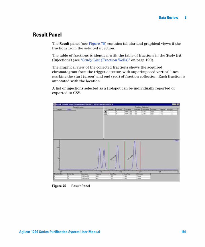
Agilent 1200 Series Purification System User Manual 191
Data Review 8
Result Panel
The Result panel (see Figure 76) contains tabular and graphical views if the fractions from the selected injection.
The table of fractions is identical with the table of fractions in the Study List (Injections) (see “Study List (Fraction Wells)” on page 190).
The graphical view of the collected fractions shows the acquired chromatogram from the trigger detector, with superimposed vertical lines marking the start (green) and end (red) of fraction collection. Each fraction is annotated with the location.
A list of injections selected as a Hotspot can be individually reported or exported to CSV.
Figure 76 Result Panel
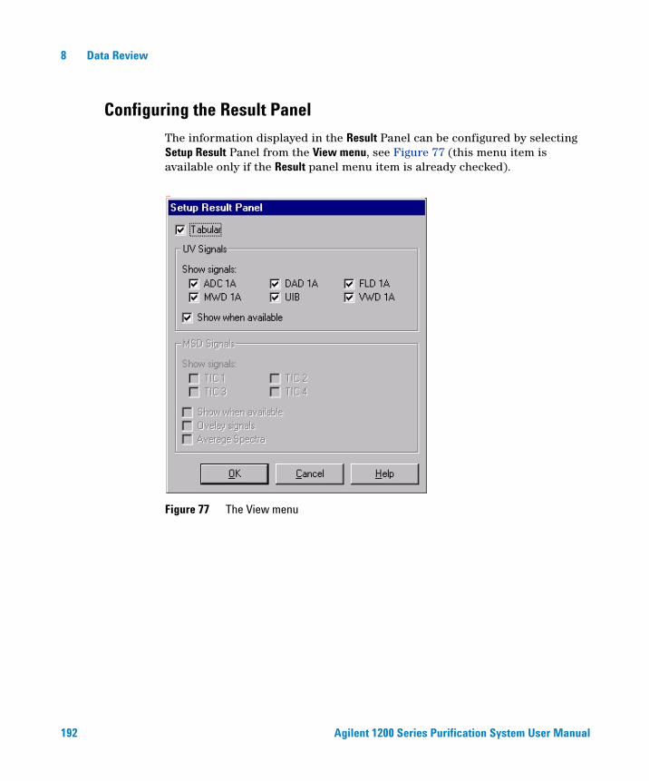
192 Agilent 1200 Series Purification System User Manual
8 Data Review
Configuring the Result Panel
The information displayed in the Result Panel can be configured by selecting Setup Result Panel from the View menu, see Figure 77 (this menu item is available only if the Result panel menu item is already checked).
aam
Figure 77 The View menu
Agilent 1200 Series Purification System User Manual 193
Data Review 8
Tabular
If Tabular is checked, then the results table, if available, is displayed in the upper part of the Result Panel.
UV-Detector signals
The following UV-detectors and signals are supported:
• HP35900E Analog/Digital converter (ADC) for connection of non-1200 detectors: signal ADC1A
• Agilent Fraction Collector UIB: signal AFC1O
• Agilent G1315B/C DAD: signal DAD1A
• Agilent G1321A FLD: signal FLD1A
• Agilent G1365B/C MWD: signal MWD1A
• Agilent G1314B/C VWD: signal VWD1A
If the Show when Available item is unchecked, the signals of the checked detectors are displayed in the Result Panel, if they have been acquired in the run. If the signals of the checked detectors have not been acquired in the run, an empty graphic is shown indicating that this signal was not found.
If the Show when Available item is checked, all available UV-detector signals in the current data file are displayed.
MS Detector signals
The Agilent G1946D and G1956B MSD have the ability to acquire a TIC for up to four channels: TIC 1- 4. The Agilent ChemStation method determines which TIC will be acquired and stored in the data file. Menu items MSD 1 - 4 correspond to the four TIC 1 – 4.
If the Show when Available item is unchecked, the TICs corresponding to the checked MSD 1 – 4 signals will be displayed in the Result Panel, if the MSD signals have been acquired in the run. If the checked MSD signal has not been acquired in the run, an empty graphic is shown indicating that this signal was not found.
If the Show when Available item is checked, the TICs corresponding to all the acquired MSD signals in the current data file are displayed.
To view the TICs in one graphic using the same time axis, the Overlay Mode menu item can be checked.

194 Agilent 1200 Series Purification System User Manual
8 Data Review
Average Spectra
If this menu item is checked, an average spectrum is displayed below the TIC.
View Mode Tools
To view data in other samples in this study, you can either click on the desired sample in the Sampler diagram, or use the View mode navigation tools available along the toolbar. These tools are available only if the View mode button has been selected on the far left side of the toolbar (Figure 78).
The following tools are specific to View Mode:
Shows the results for the first injection on the previous sample plate. This tool will be available only if the study was run using a high performance autosampler or a dual-loop autosampler.
Shows the results for the first injection on the next sample plate. This tool will be available only if the study was run using a high performance autosampler or a dual-loop autosampler.
Shows the details for the previous sample.
Shows the details for the next sample.
Figure 78 The View mode tool

Agilent 1200 Series Purification System User Manual 195
Data Review 8
Shows the results for the previous injection. Since the injection order might not correspond to the sample numbering, then the previous injection might be different than the previous sample.
Shows the results for the next injection. Since the injection order might not correspond to the sample numbering, then the next injection might be different than the next sample.
Shows the results for the previous pool. This tool is available only if multiple pools were acquired in the study.
Shows the results for the next pool. This tool is available only if multiple pools were acquired in the study.
Shows the results for the previous target (disabled if none or only one target mass is specified for a sample). Clicking this button is equivalent to placing the pointer one row up in the Target Masses table in the Results Panel.
Shows the results for the next target (disabled if none or only one target mass is specified for a sample). Clicking this button is equivalent to placing the pointer one row down in the Target Masses table in the Results Panel.
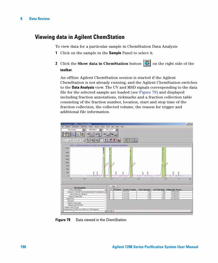
196 Agilent 1200 Series Purification System User Manual
8 Data Review
Viewing data in Agilent ChemStation
To view data for a particular sample in ChemStation Data Analysis
1 Click on the sample in the Sample Panel to select it.
2 Click the Show data in ChemStation button on the right side of the
toolbar.
An offline Agilent ChemStation session is started if the Agilent ChemStation is not already running, and the Agilent ChemStation switches to the Data Analysis view. The UV and MSD signals corresponding to the data file for the selected sample are loaded (see Figure 79) and displayed including fraction annotations, tickmarks and a fraction collection table consisting of the fraction number, location, start and stop time of the fraction collection, the collected volume, the reason for trigger and additional file information.
Figure 79 Data viewed in the ChemStation

Agilent 1200 Series Purification System User Manual 197
Data Review 8
The functions in Agilent ChemStation Data Analysis can be used to further evaluate the data.

198 Agilent 1200 Series Purification System User Manual
8 Data Review
199
Agilent 1200 Series Purification SystemUser Manual
Agilent Technologies
9Reports
Introduction 200
Agilent ChemStation Reporting 202
Purification/Hi Throughput Reports 205
This chapter describes the reporting options that are provided by the Purification/Hi Throughput software.

200 Agilent 1200 Series Purification System User Manual
9 Reports
Introduction
You specify the reports that you want to produce in the Specify Report dialog box (see Figure 80). You can output reports from both the Agilent ChemStation and the Purification/Hi Throughput software.
Figure 80 The Specify Report dialog box
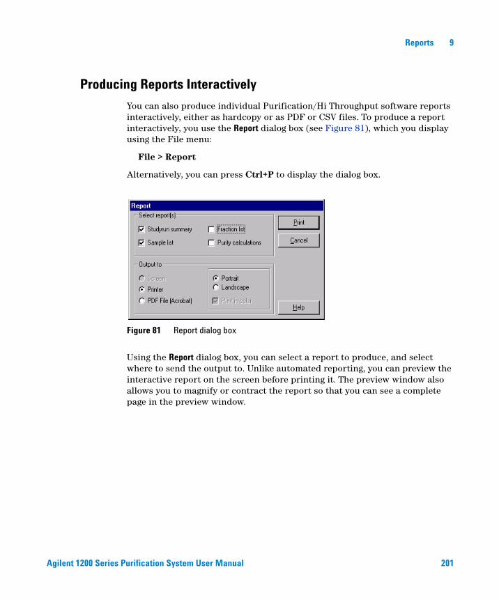
Agilent 1200 Series Purification System User Manual 201
Reports 9
Producing Reports Interactively
You can also produce individual Purification/Hi Throughput software reports interactively, either as hardcopy or as PDF or CSV files. To produce a report interactively, you use the Report dialog box (see Figure 81), which you display using the File menu:
File > Report
Alternatively, you can press Ctrl+P to display the dialog box.
Using the Report dialog box, you can select a report to produce, and select where to send the output to. Unlike automated reporting, you can preview the interactive report on the screen before printing it. The preview window also allows you to magnify or contract the report so that you can see a complete page in the preview window.
Figure 81 Report dialog box
202 Agilent 1200 Series Purification System User Manual
9 Reports
Agilent ChemStation Reporting
The standard Agilent ChemStation reports can be produced as specified in the Agilent ChemStation method or enhanced with the inclusion of fraction annotation on the chromatogram and/or a print-out of the fraction table. In addition, you can choose for the fraction annotations, whether you also want to label each well and the fractions.
To print a standard Agilent ChemStation report, you mark the Agilent ChemStation Data Analysis Report check box.
Fraction Annotation
When you select to include fraction annotation, the beginning and end of each fraction is marked on your chromatograms (as in Figure 82). The beginning of the collection of each fraction is marked with a green vertical line; the end of collection is marked by a red vertical line. The dotted horizontal line is the threshold that you specified in the peak detection parameters. In addition, you can choose, whether you want to label each well and each fraction, also.
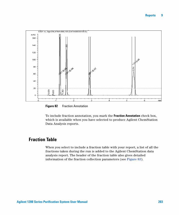
Agilent 1200 Series Purification System User Manual 203
Reports 9
To include fraction annotation, you mark the Fraction Annotation check box, which is available when you have selected to produce Agilent ChemStation Data Analysis reports.
Fraction Table
When you select to include a fraction table with your report, a list of all the fractions taken during the run is added to the Agilent ChemStation data analysis report. The header of the fraction table also gives detailed information of the fraction collection parameters (see Figure 83).
Figure 82 Fraction Annotation
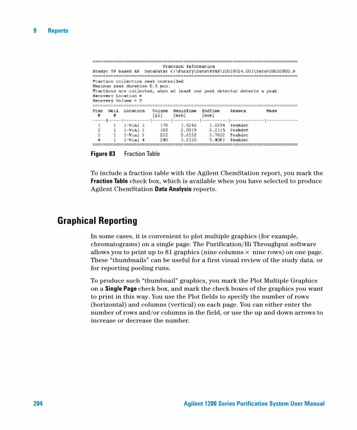
204 Agilent 1200 Series Purification System User Manual
9 Reports
To include a fraction table with the Agilent ChemStation report, you mark the Fraction Table check box, which is available when you have selected to produce Agilent ChemStation Data Analysis reports.
Graphical Reporting
In some cases, it is convenient to plot multiple graphics (for example, chromatograms) on a single page. The Purification/Hi Throughput software allows you to print up to 81 graphics (nine columns × nine rows) on one page. These “thumbnails” can be useful for a first visual review of the study data. or for reporting pooling runs.
To produce such “thumbnail” graphics, you mark the Plot Multiple Graphics on a Single Page check box, and mark the check boxes of the graphics you want to print in this way. You use the Plot fields to specify the number of rows (horizontal) and columns (vertical) on each page. You can either enter the number of rows and/or columns in the field, or use the up and down arrows to increase or decrease the number.
Figure 83 Fraction Table
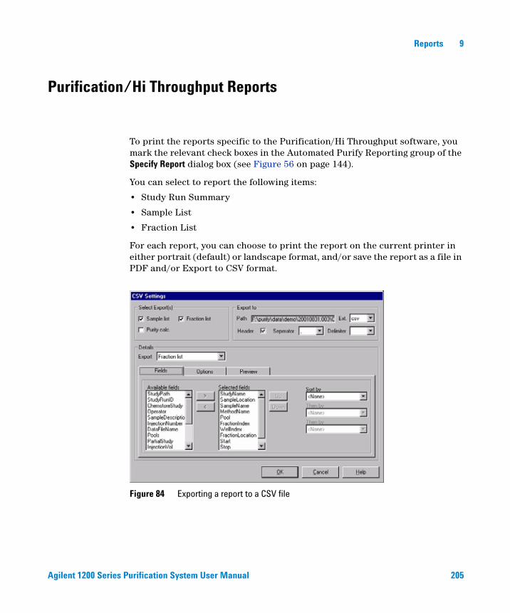
Agilent 1200 Series Purification System User Manual 205
Reports 9
Purification/Hi Throughput Reports
To print the reports specific to the Purification/Hi Throughput software, you mark the relevant check boxes in the Automated Purify Reporting group of the Specify Report dialog box (see Figure 56 on page 144).
You can select to report the following items:
• Study Run Summary
• Sample List
• Fraction List
For each report, you can choose to print the report on the current printer in either portrait (default) or landscape format, and/or save the report as a file in PDF and/or Export to CSV format.
Figure 84 Exporting a report to a CSV file
206 Agilent 1200 Series Purification System User Manual
9 Reports
Press the CSV Settings / Export button in the report setup to specify a CSV-file to export to:
• Choose, whether you want to export the sample list and / or fraction list (Purity Calculations is not supported with CS B.01.01 and Purify B.01.01).
• Choose a file destination and type, header, separator and delimiter
• Specify the report Details for the sample list and / or fraction list: You can select fields by moving them from the list of available fields to selected fields. You can apply multiple sort patterns.
• In the Options tab, you can apply several different filter options.
• In the Preview tab, you can preview the CSV files as currently defined.
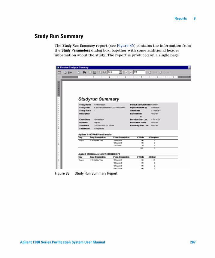
Agilent 1200 Series Purification System User Manual 207
Reports 9
Study Run Summary
The Study Run Summary report (see Figure 85) contains the information from the Study Parameters dialog box, together with some additional header information about the study. The report is produced on a single page.
Figure 85 Study Run Summary Report
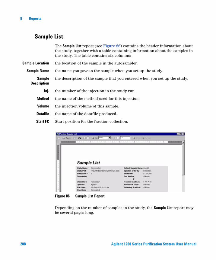
208 Agilent 1200 Series Purification System User Manual
9 Reports
Sample List
The Sample List report (see Figure 86) contains the header information about the study, together with a table containing information about the samples in the study. The table contains six columns:
Sample Location the location of the sample in the autosampler.
Sample Name the name you gave to the sample when you set up the study.
SampleDescription
the description of the sample that you entered when you set up the study.
Inj. the number of the injection in the study run.
Method the name of the method used for this injection.
Volume the injection volume of this sample.
Datafile the name of the datafile produced.
Start FC Start position for the fraction collection.
Depending on the number of samples in the study, the Sample List report may be several pages long.
Figure 86 Sample List Report
Agilent 1200 Series Purification System User Manual 209
Reports 9
Fraction List
The Fraction List report (see Figure 87 on page 210) contains the header information about the study, together with a table containing information about the fractions collected in the study. The table contains eleven columns:
Sample Location the location of the sample in the autosampler.
Sample Name the name you gave to the sample when you set up the study.
Method the name of the method used for this injection.
Pool the number of the pool (always 1 if no pooling was set up).
Fract. No. the number of the fraction.
Well No. the number of the well for this fraction (always 1 if the fraction volume did not overfill the well)
Location the location of the fraction in the fraction collector.
Start the collection start time of the fraction.
Stop the collection end time of the fraction.
Reason the trigger reason for the start of fraction collection.
Masses Masses used for fraction trigger (MSD only)
Fraction Volumes Fraction Volumes are only visible, if the display type is “Portrait”
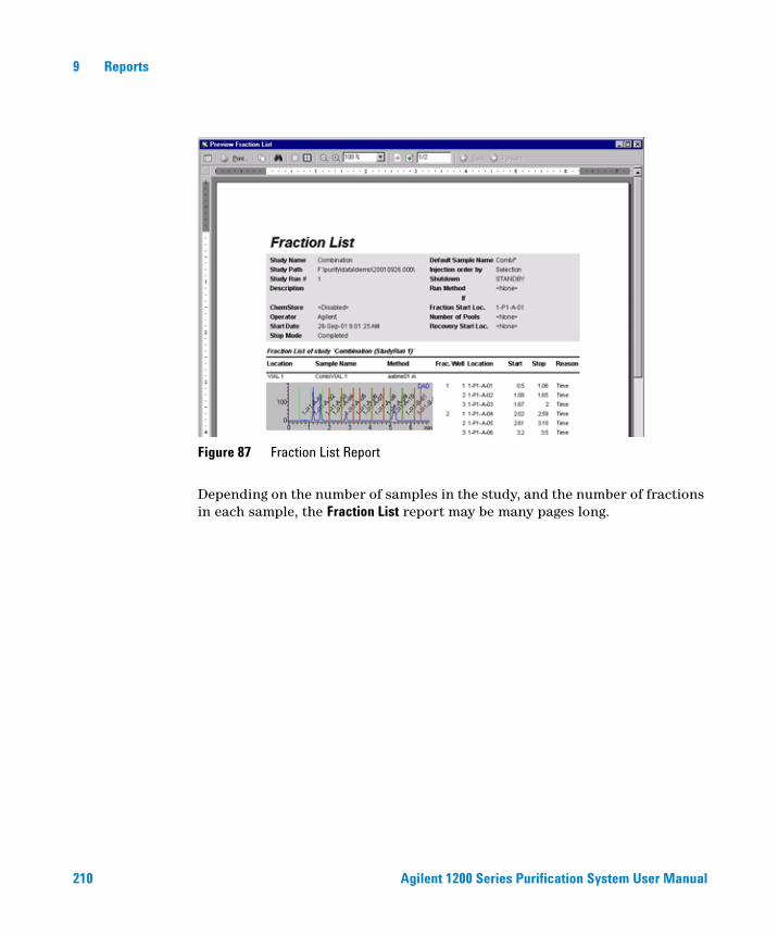
210 Agilent 1200 Series Purification System User Manual
9 Reports
Depending on the number of samples in the study, and the number of fractions in each sample, the Fraction List report may be many pages long.
Figure 87 Fraction List Report

211
Agilent 1200 Series Purification SystemUser Manual
Agilent Technologies
10Directory Structure and File Naming
Directory Structure 212
The Data Folder 213
Data File Naming 214
This chapter explains how the Purification/Hi Throughput files are organized, and how data files are named.
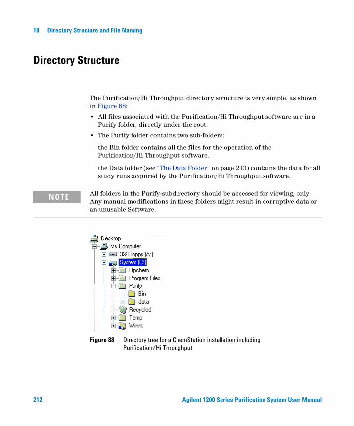
212 Agilent 1200 Series Purification System User Manual
10 Directory Structure and File Naming
Directory Structure
The Purification/Hi Throughput directory structure is very simple, as shown in Figure 88:
• All files associated with the Purification/Hi Throughput software are in a Purify folder, directly under the root.
• The Purify folder contains two sub-folders:
the Bin folder contains all the files for the operation of the Purification/Hi Throughput software.
the Data folder (see “The Data Folder” on page 213) contains the data for all study runs acquired by the Purification/Hi Throughput software.
NOTE All folders in the Purify-subdirectory should be accessed for viewing, only. Any manual modifications in these folders might result in corruptive data or an unusable Software.
Figure 88 Directory tree for a ChemStation installation including Purification/Hi Throughput
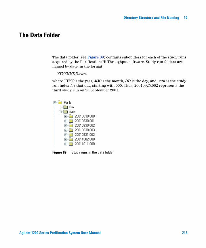
Agilent 1200 Series Purification System User Manual 213
Directory Structure and File Naming 10
The Data Folder
The data folder (see Figure 89) contains sub-folders for each of the study runs acquired by the Purification/Hi Throughput software. Study run folders are named by date, in the format
YYYYMMDD.run,
where YYYY is the year, MM is the month, DD is the day, and .run is the study run index for that day, starting with 000. Thus, 20010925.002 represents the third study run on 25 September 2001.
Figure 89 Study runs in the data folder

214 Agilent 1200 Series Purification System User Manual
10 Directory Structure and File Naming
Data File Naming
Within each study run folder are sub-folders containing the data and methods associated with the study run. Data files for a study run are contained in folders with the extension .d. They have the general format
SSSSNNPP.d
where SSSS is the sample number, starting with 0001; NN is the injection number, starting with 00; and PP is the pool number, starting with 01. If no pooling has been specified, then PP is always 00. Thus, 00030200.d represents the third injection of the third sample (no pooling), and 00030102.d represents the second pool of the second injection of the third sample. Figure 90 shows a list of the data files from a study run where no pooling was specified, but each sample was injected twice.
Figure 90 Data files from a study run without pooling
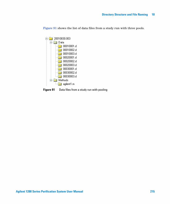
Agilent 1200 Series Purification System User Manual 215
Directory Structure and File Naming 10
Figure 91 shows the list of data files from a study run with three pools.
Figure 91 Data files from a study run with pooling
216 Agilent 1200 Series Purification System User Manual
10 Directory Structure and File Naming
217
Agilent 1200 Series Purification SystemUser Manual
Agilent Technologies
11Checkout Procedures
Introduction 218
UV-triggered AS Fraction Collection Checkout 220
UV-triggered PS Fraction Collection Checkout 235
MSD-triggered AS Fraction Collection Checkout 248
MSD-triggered PS Fraction Collection Checkout 261
This chapter describes the checkout procedures that are used to verify correct operation of hardware and software.
218 Agilent 1200 Series Purification System User Manual
11 Checkout Procedures
Introduction
This chapter describes four different checkout procedures. These procedures are used to verify the operation of the Agilent Purification Hi/Throughput software and its associated hardware components.
UV-triggered AS fraction collection checkout procedure, (see page 220)
This checkout procedure verifies the operation of the Agilent Fraction Collector AS G1364C used with the Agilent Purification/Hi Throughput software and in combination with the associated hardware components.
The Checkout Procedure consists of the following activities:
• Preparing the Agilent 1200 Series LC
• Setting the study parameters
• Starting the analysis and collecting fractions
• Reanalyzing the fractions
UV-triggered PS fraction collection checkout procedure, (see page 235)
This checkout procedure verifies the operation of the Agilent Fraction Collector PS G1364B used with the Agilent Purification/Hi Throughput software and in combination with the associated hardware components.
The Checkout Procedure consists of the following activities:
• Preparing the Agilent 1200 Series LC
• Setting the study parameters
• Starting the analysis and collecting fractions
• Reanalyzing the fractions
MSD-triggered AS fraction collection checkout procedure, (see page 248)
This checkout procedure verifies the operation of the Agilent Fraction Collector AS G1364C and the Agilent Mass Based Fraction Collection Kit G1968C used with the Agilent Purification Hi/Throughput software and in combination with the associated hardware components.
Agilent 1200 Series Purification System User Manual 219
Checkout Procedures 11
The checkout procedure consists of the following activities:
• Preparing the Agilent 1200 Series LC and LC/MSD
• Setting the checkout method parameters
• Running the checkout and collecting fractions
• Reviewing the results and reanalyzing a fraction
MSD-triggered PS fraction collection checkout procedure, (see page 261)
This checkout procedure verifies the operation of the Agilent Fraction Collector PS G1364B and the Agilent Mass Based Fraction Collection Kit G1968C used with the Agilent Purification Hi/Throughput software and in combination with the associated hardware components.
The checkout procedure consists of the following activities:
• Preparing the Agilent 1200 Series LC and LC/MSD
• Setting the checkout method parameters
• Running the checkout and collecting fractions
• Reviewing the results and reanalyzing a fraction
220 Agilent 1200 Series Purification System User Manual
11 Checkout Procedures
UV-triggered AS Fraction Collection Checkout
The Checkout Procedure consists of the following activities:
• Preparing the Agilent 1200 Series LC
• Setting the study parameters
• Starting the analysis and collecting fractions
• Reanalyzing the fractions
What you will Need
Instruments
• Agilent 1200 Series high performance autosampler or Agilent 1200 Series standard autosampler, Agilent 1200 Series preparative autosampler or Agilent 1200 Series dual-loop autosampler (optional thermostatted version)
• Agilent 1200 Series Isocratic or Quaternary or Binary Pump with Agilent 1200 Series Vacuum Degasser
• Agilent 1200 Series Fraction Collector AS (optional thermostatted version)
• Agilent 1200 Series Variable Wavelength Detector (with analytical flow cell) or Agilent 1200 Series Multi-wavelength Detector (with analytical flow cell) or Agilent 1200 Series Diode Array Detector (Detector (with analytical flow cell)
Software
• Agilent ChemStation Software (G2170AA) A.09.01 or Higher
• Agilent Purification Hi/Throughput Software (G2262AA) A.01.01
Column
• Zorbax Eclipse XDB-C8 4.6 mm x 15 cm 5 µm (Part number 993967-906)

Agilent 1200 Series Purification System User Manual 221
Checkout Procedures 11
Solvents
• HPLC grade Bi-distilled water
• HPLC grade Acetonitrile
Sample
• Isocratic Checkout Sample (Part number 01080-68704)
• Delay calibrant (part number G1946-85020)
Step 1: Calibrating the Delay Volume
Before running the fraction collection, the delay volume must be determined. This procedure determines the delay volume relative to the configured detector.
See “Delay Volume Calibration” on page 93 for the correct procedures.
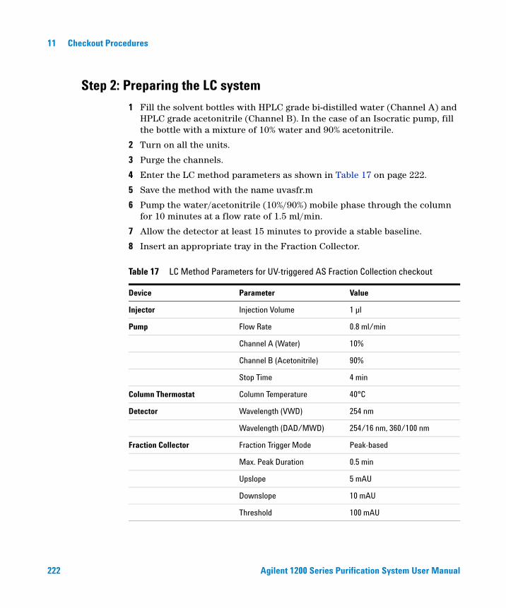
222 Agilent 1200 Series Purification System User Manual
11 Checkout Procedures
Step 2: Preparing the LC system
1 Fill the solvent bottles with HPLC grade bi-distilled water (Channel A) and HPLC grade acetonitrile (Channel B). In the case of an Isocratic pump, fill the bottle with a mixture of 10% water and 90% acetonitrile.
2 Turn on all the units.
3 Purge the channels.
4 Enter the LC method parameters as shown in Table 17 on page 222.
5 Save the method with the name uvasfr.m
6 Pump the water/acetonitrile (10%/90%) mobile phase through the column for 10 minutes at a flow rate of 1.5 ml/min.
7 Allow the detector at least 15 minutes to provide a stable baseline.
8 Insert an appropriate tray in the Fraction Collector.
Table 17 LC Method Parameters for UV-triggered AS Fraction Collection checkout
Device Parameter Value
Injector Injection Volume 1 µl
Pump Flow Rate 0.8 ml/min
Channel A (Water) 10%
Channel B (Acetonitrile) 90%
Stop Time 4 min
Column Thermostat Column Temperature 40°C
Detector Wavelength (VWD) 254 nm
Wavelength (DAD/MWD) 254/16 nm, 360/100 nm
Fraction Collector Fraction Trigger Mode Peak-based
Max. Peak Duration 0.5 min
Upslope 5 mAU
Downslope 10 mAU
Threshold 100 mAU
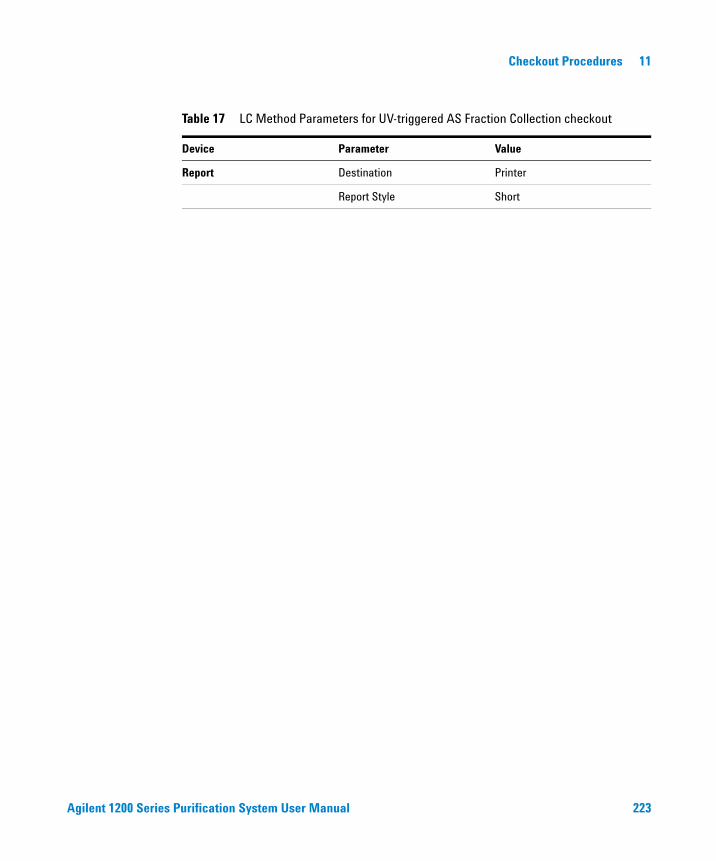
Agilent 1200 Series Purification System User Manual 223
Checkout Procedures 11
Report Destination Printer
Report Style Short
Table 17 LC Method Parameters for UV-triggered AS Fraction Collection checkout
Device Parameter Value
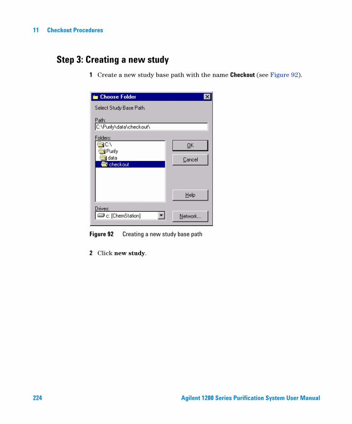
224 Agilent 1200 Series Purification System User Manual
11 Checkout Procedures
Step 3: Creating a new study
1 Create a new study base path with the name Checkout (see Figure 92).
2 Click new study.
Figure 92 Creating a new study base path
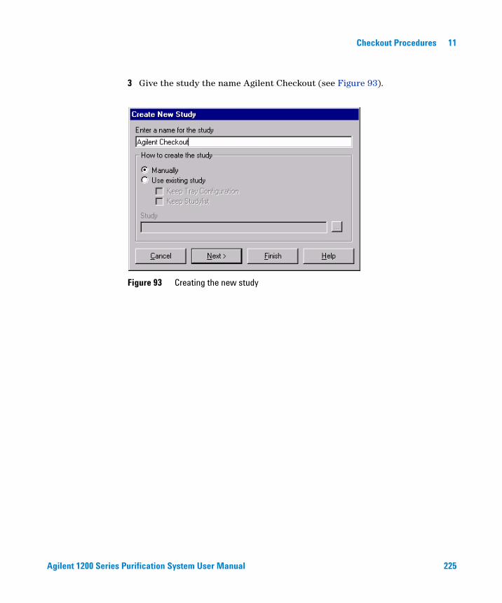
Agilent 1200 Series Purification System User Manual 225
Checkout Procedures 11
3 Give the study the name Agilent Checkout (see Figure 93).
Figure 93 Creating the new study

226 Agilent 1200 Series Purification System User Manual
11 Checkout Procedures
4 Complete the study parameters as shown in Figure 94.
Figure 94 Study parameters for UV-triggered AS checkout

Agilent 1200 Series Purification System User Manual 227
Checkout Procedures 11
5 Specify the report as shown in Figure 95. Use Next and Previous to navigate through the Study Setup Wizard.
Figure 95 Report parameters for UV-triggered AS checkout
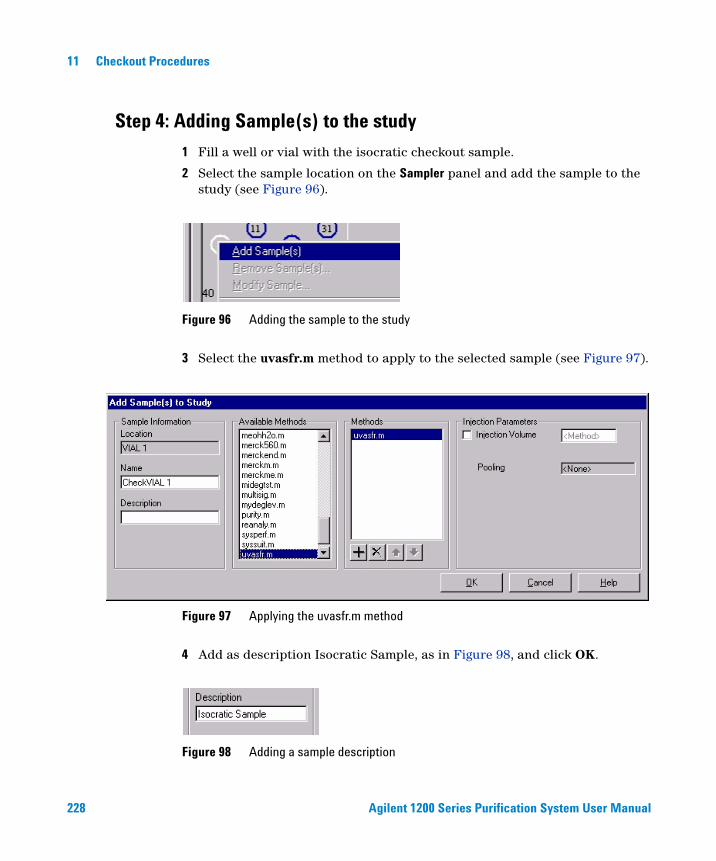
228 Agilent 1200 Series Purification System User Manual
11 Checkout Procedures
Step 4: Adding Sample(s) to the study
1 Fill a well or vial with the isocratic checkout sample.
2 Select the sample location on the Sampler panel and add the sample to the study (see Figure 96).
3 Select the uvasfr.m method to apply to the selected sample (see Figure 97).
4 Add as description Isocratic Sample, as in Figure 98, and click OK.
Figure 96 Adding the sample to the study
Figure 97 Applying the uvasfr.m method
Figure 98 Adding a sample description
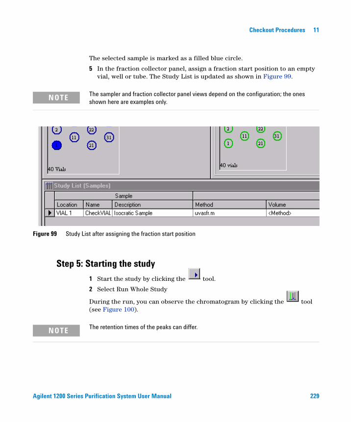
Agilent 1200 Series Purification System User Manual 229
Checkout Procedures 11
The selected sample is marked as a filled blue circle.
5 In the fraction collector panel, assign a fraction start position to an empty vial, well or tube. The Study List is updated as shown in Figure 99.
Step 5: Starting the study
1 Start the study by clicking the tool.
2 Select Run Whole Study
During the run, you can observe the chromatogram by clicking the tool (see Figure 100).
NOTE The sampler and fraction collector panel views depend on the configuration; the ones shown here are examples only.
Figure 99 Study List after assigning the fraction start position
NOTE The retention times of the peaks can differ.

230 Agilent 1200 Series Purification System User Manual
11 Checkout Procedures
Figure 100 The chromatogram as displayed during a run

Agilent 1200 Series Purification System User Manual 231
Checkout Procedures 11
Step 6: Reviewing the results
1 When the study run is finished, verify that you have four fractions collected in the vials or wells or tubes.
2 Verify that you have four green fraction locations on the fraction collector panel, as in Figure 101.
Figure 101 Panels after fraction collection
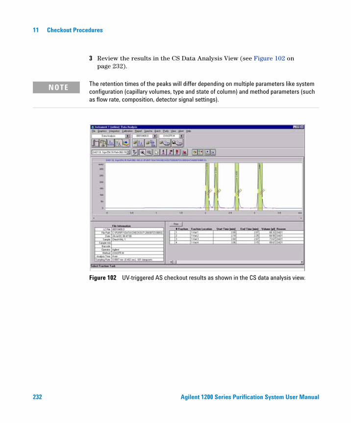
232 Agilent 1200 Series Purification System User Manual
11 Checkout Procedures
3 Review the results in the CS Data Analysis View (see Figure 102 on page 232).
NOTE The retention times of the peaks will differ depending on multiple parameters like system configuration (capillary volumes, type and state of column) and method parameters (such as flow rate, composition, detector signal settings).
Figure 102 UV-triggered AS checkout results as shown in the CS data analysis view.
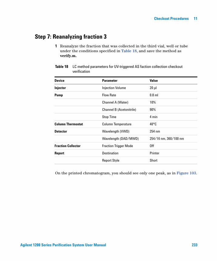
Agilent 1200 Series Purification System User Manual 233
Checkout Procedures 11
Step 7: Reanalyzing fraction 3
1 Reanalyze the fraction that was collected in the third vial, well or tube under the conditions specified in Table 18, and save the method as verify.m.
On the printed chromatogram, you should see only one peak, as in Figure 103.
Table 18 LC method parameters for UV-triggered AS faction collection checkout verification
Device Parameter Value
Injector Injection Volume 20 μl
Pump Flow Rate 0.8 ml
Channel A (Water) 10%
Channel B (Acetonitrile) 90%
Stop Time 4 min
Column Thermostat Column Temperature 40°C
Detector Wavelength (VWD) 254 nm
Wavelength (DAD/MWD) 254/16 nm, 360/100 nm
Fraction Collector Fraction Trigger Mode Off
Report Destination Printer
Report Style Short
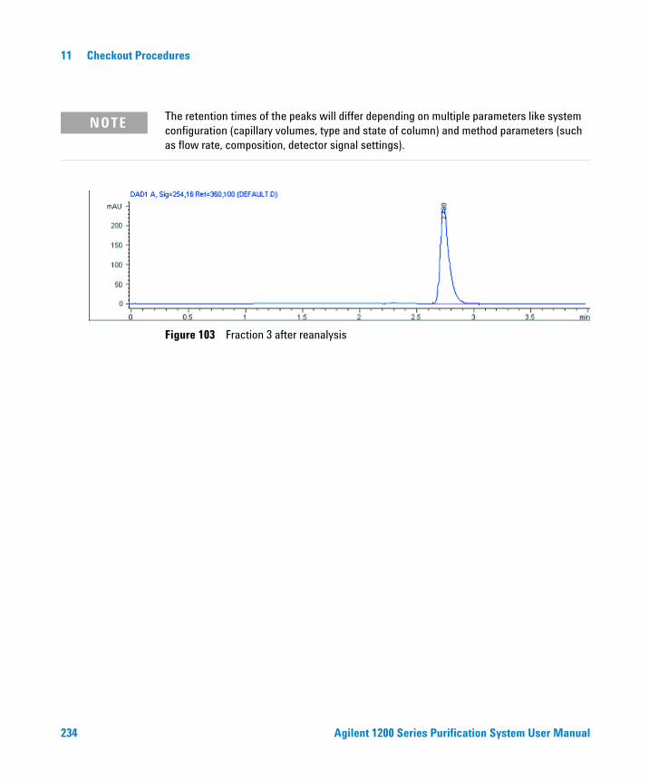
234 Agilent 1200 Series Purification System User Manual
11 Checkout Procedures
NOTE The retention times of the peaks will differ depending on multiple parameters like system configuration (capillary volumes, type and state of column) and method parameters (such as flow rate, composition, detector signal settings).
Figure 103 Fraction 3 after reanalysis

Agilent 1200 Series Purification System User Manual 235
Checkout Procedures 11
UV-triggered PS Fraction Collection Checkout
The Checkout Procedure consists of the following activities:
• Preparing the Agilent 1200 Series LC
• Setting the study parameters
• Starting the analysis and collecting fractions
• Reanalyzing the fractions
What you will Need
Instruments
• Agilent 1200 Series Preparative Autosampler (optional thermostatted version)
• Agilent 1200 Preparative Pump
• Agilent 1200 Series Fraction Collector PS (optional thermostatted version)
• Agilent 1200 Series Multi-wavelength Detector (with preparative flow cells) or 1200 Series Diode Array Detector (with preparative flow cells)
Software
• Agilent ChemStation Software (G2170AA) A.09.01 or Higher
• Agilent Purification Hi/Throughput Software (G2262AA) A.01.01
Column
• 9.46 mm x 50 mm SB-C18 (Part number 846975-202)
Solvents
• HPLC grade Bi-distilled water
• HPLC grade Acetonitrile
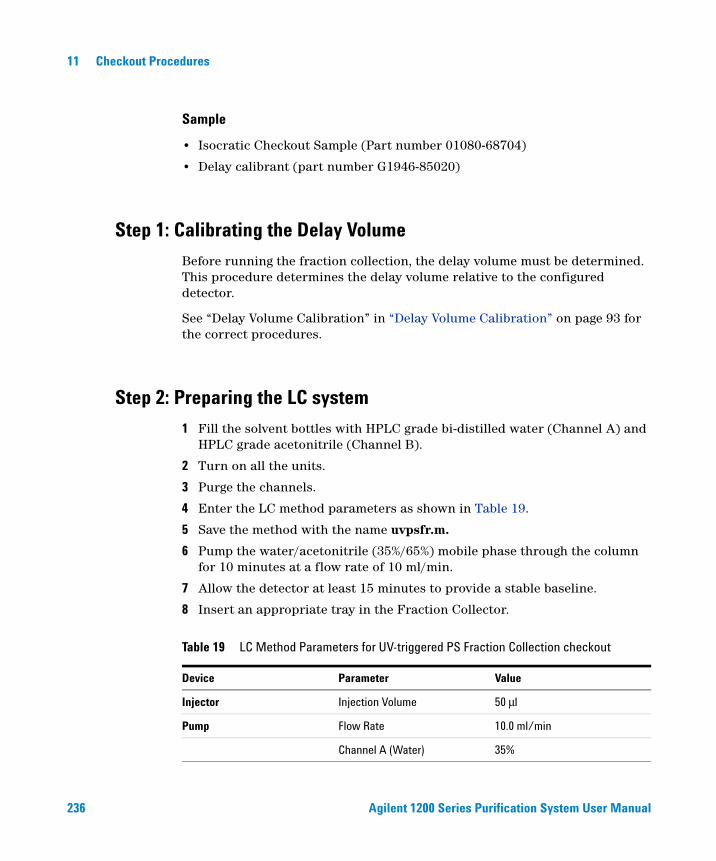
236 Agilent 1200 Series Purification System User Manual
11 Checkout Procedures
Sample
• Isocratic Checkout Sample (Part number 01080-68704)
• Delay calibrant (part number G1946-85020)
Step 1: Calibrating the Delay Volume
Before running the fraction collection, the delay volume must be determined. This procedure determines the delay volume relative to the configured detector.
See “Delay Volume Calibration” in “Delay Volume Calibration” on page 93 for the correct procedures.
Step 2: Preparing the LC system
1 Fill the solvent bottles with HPLC grade bi-distilled water (Channel A) and HPLC grade acetonitrile (Channel B).
2 Turn on all the units.
3 Purge the channels.
4 Enter the LC method parameters as shown in Table 19.
5 Save the method with the name uvpsfr.m.
6 Pump the water/acetonitrile (35%/65%) mobile phase through the column for 10 minutes at a flow rate of 10 ml/min.
7 Allow the detector at least 15 minutes to provide a stable baseline.
8 Insert an appropriate tray in the Fraction Collector.
Table 19 LC Method Parameters for UV-triggered PS Fraction Collection checkout
Device Parameter Value
Injector Injection Volume 50 μl
Pump Flow Rate 10.0 ml/min
Channel A (Water) 35%
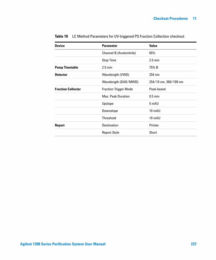
Agilent 1200 Series Purification System User Manual 237
Checkout Procedures 11
Channel B (Acetonitrile) 65%
Stop Time 2.5 min
Pump Timetable 2.5 min 75% B
Detector Wavelength (VWD) 254 nm
Wavelength (DAD/MWD) 254/16 nm, 360/100 nm
Fraction Collector Fraction Trigger Mode Peak-based
Max. Peak Duration 0.5 min
Upslope 5 mAU
Downslope 10 mAU
Threshold 10 mAU
Report Destination Printer
Report Style Short
Table 19 LC Method Parameters for UV-triggered PS Fraction Collection checkout
Device Parameter Value
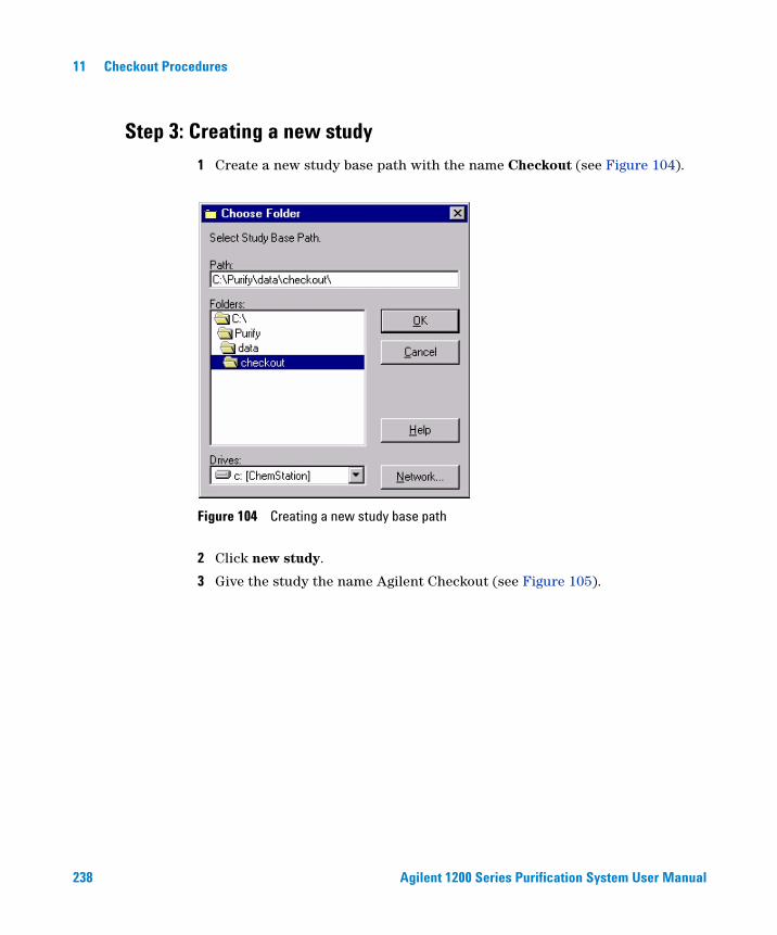
238 Agilent 1200 Series Purification System User Manual
11 Checkout Procedures
Step 3: Creating a new study
1 Create a new study base path with the name Checkout (see Figure 104).
2 Click new study.
3 Give the study the name Agilent Checkout (see Figure 105).
Figure 104 Creating a new study base path
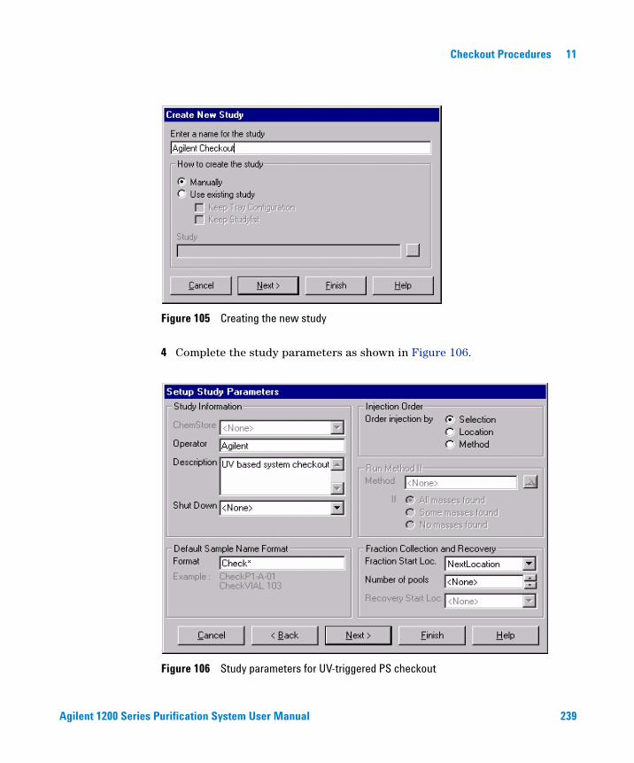
Agilent 1200 Series Purification System User Manual 239
Checkout Procedures 11
4 Complete the study parameters as shown in Figure 106.
Figure 105 Creating the new study
Figure 106 Study parameters for UV-triggered PS checkout
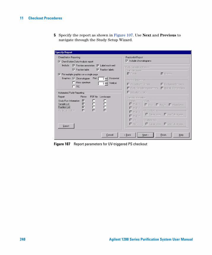
240 Agilent 1200 Series Purification System User Manual
11 Checkout Procedures
5 Specify the report as shown in Figure 107. Use Next and Previous to navigate through the Study Setup Wizard.
Figure 107 Report parameters for UV-triggered PS checkout
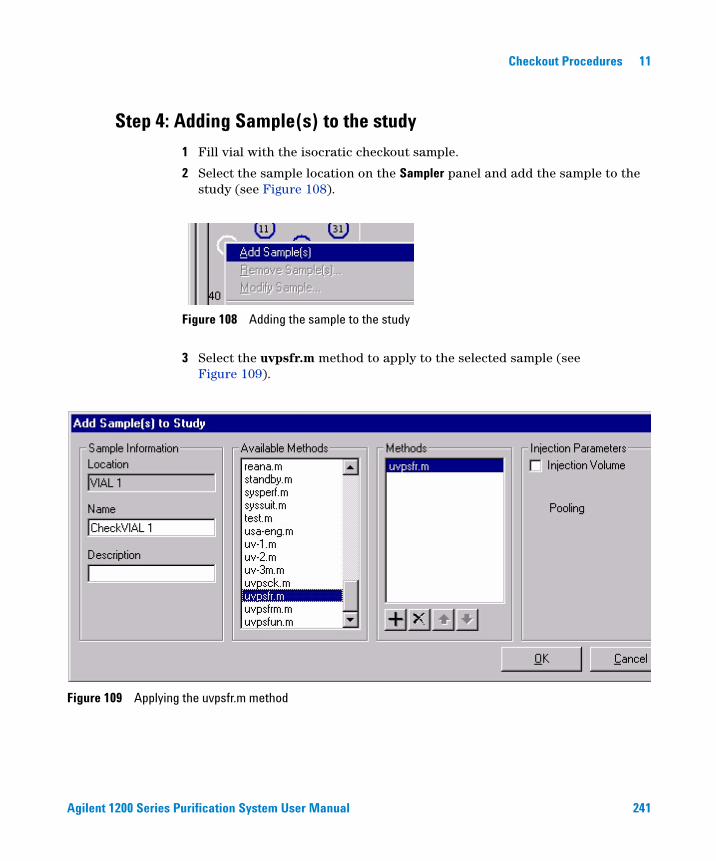
Agilent 1200 Series Purification System User Manual 241
Checkout Procedures 11
Step 4: Adding Sample(s) to the study
1 Fill vial with the isocratic checkout sample.
2 Select the sample location on the Sampler panel and add the sample to the study (see Figure 108).
3 Select the uvpsfr.m method to apply to the selected sample (see Figure 109).
Figure 108 Adding the sample to the study
Figure 109 Applying the uvpsfr.m method
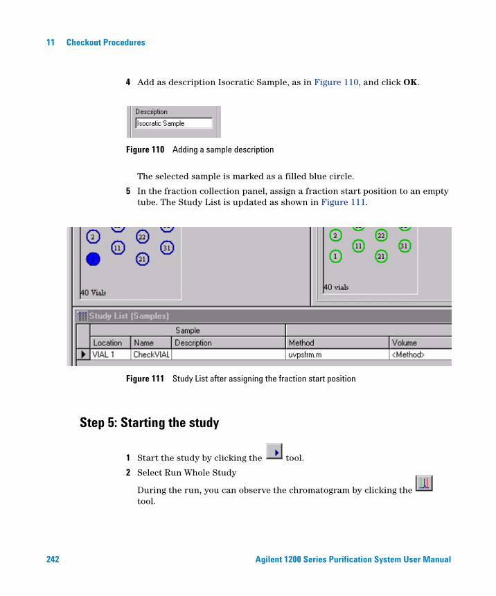
242 Agilent 1200 Series Purification System User Manual
11 Checkout Procedures
4 Add as description Isocratic Sample, as in Figure 110, and click OK.
The selected sample is marked as a filled blue circle.
5 In the fraction collection panel, assign a fraction start position to an empty tube. The Study List is updated as shown in Figure 111.
Step 5: Starting the study
1 Start the study by clicking the tool.
2 Select Run Whole Study
During the run, you can observe the chromatogram by clicking the tool.
Figure 110 Adding a sample description
Figure 111 Study List after assigning the fraction start position
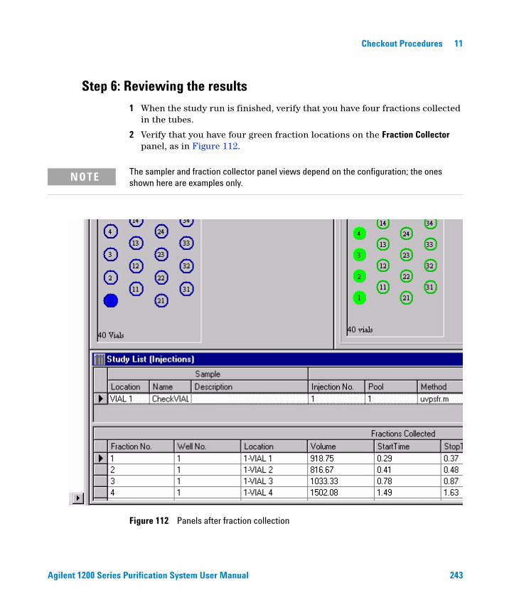
Agilent 1200 Series Purification System User Manual 243
Checkout Procedures 11
Step 6: Reviewing the results
1 When the study run is finished, verify that you have four fractions collected in the tubes.
2 Verify that you have four green fraction locations on the Fraction Collector panel, as in Figure 112.
NOTE The sampler and fraction collector panel views depend on the configuration; the ones shown here are examples only.
Figure 112 Panels after fraction collection
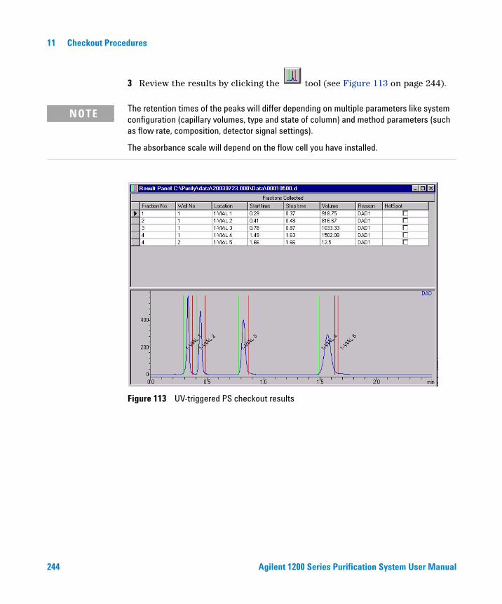
244 Agilent 1200 Series Purification System User Manual
11 Checkout Procedures
3 Review the results by clicking the tool (see Figure 113 on page 244).
NOTE The retention times of the peaks will differ depending on multiple parameters like system configuration (capillary volumes, type and state of column) and method parameters (such as flow rate, composition, detector signal settings).
The absorbance scale will depend on the flow cell you have installed.
Figure 113 UV-triggered PS checkout results
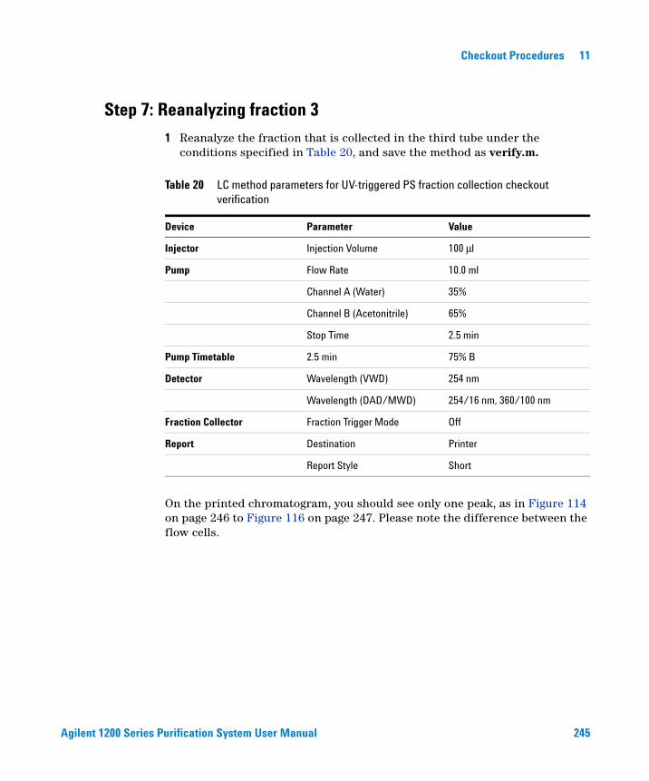
Agilent 1200 Series Purification System User Manual 245
Checkout Procedures 11
Step 7: Reanalyzing fraction 3
1 Reanalyze the fraction that is collected in the third tube under the conditions specified in Table 20, and save the method as verify.m.
On the printed chromatogram, you should see only one peak, as in Figure 114 on page 246 to Figure 116 on page 247. Please note the difference between the flow cells.
Table 20 LC method parameters for UV-triggered PS fraction collection checkout verification
Device Parameter Value
Injector Injection Volume 100 μl
Pump Flow Rate 10.0 ml
Channel A (Water) 35%
Channel B (Acetonitrile) 65%
Stop Time 2.5 min
Pump Timetable 2.5 min 75% B
Detector Wavelength (VWD) 254 nm
Wavelength (DAD/MWD) 254/16 nm, 360/100 nm
Fraction Collector Fraction Trigger Mode Off
Report Destination Printer
Report Style Short
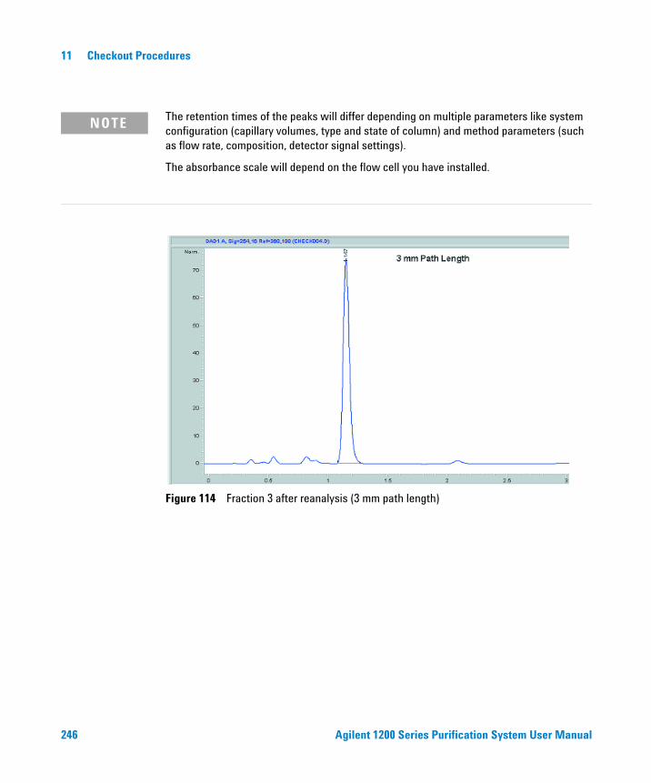
246 Agilent 1200 Series Purification System User Manual
11 Checkout Procedures
NOTE The retention times of the peaks will differ depending on multiple parameters like system configuration (capillary volumes, type and state of column) and method parameters (such as flow rate, composition, detector signal settings).
The absorbance scale will depend on the flow cell you have installed.
Figure 114 Fraction 3 after reanalysis (3 mm path length)

Agilent 1200 Series Purification System User Manual 247
Checkout Procedures 11
Figure 115 Fraction 3 after reanalysis (0.3 mm path length)
Figure 116 Fraction 3 after reanalysis (0.06 mm path length)
248 Agilent 1200 Series Purification System User Manual
11 Checkout Procedures
MSD-triggered AS Fraction Collection Checkout
The checkout procedure consists of the following activities:
• Preparing the Agilent 1200 Series LC and LC/MSD
• Setting the checkout method parameters
• Running the checkout and collecting fractions
• Reviewing the results and reanalyzing a fraction
What you will need
Instruments
• Agilent 1200 Series high performance autosampler or Agilent 1200 Series standard autosampler (optional thermostatted version).
• Agilent 1200 Series Quaternary or Binary Pump with Agilent 1200 Series Vacuum Degasser
• Agilent 1200 Series Isocratic Pump with solvent bottle to be used as the make-up pump for the LC/MSD.
• Agilent 1200 Series Fraction Collector Analytical Scale (optional thermostatted version)
• Agilent 1200 Series LC/MSD (G1946B,C, or G1956A,B)
• G1968C Mass-Based Fraction Collection Kit
Software
• Agilent LC/MSD ChemStation Software (G2710AA) rev. B.01.01 or higher
Column
• Zorbax SB-C18, 9.4 mm x 5.0 cm, 5um (part number 846975-202, included in G1968C mass-based fraction collection kit)
Agilent 1200 Series Purification System User Manual 249
Checkout Procedures 11
Solvents
• HPLC grade Bi-distilled water
• HPLC grade Acetonitrile
• Acetic or Formic acid
Sample
• Delay calibrant (part number G1946-85020, included in G1968C mass-based fraction collection kit)
• Electrospray LC Demo Sample (part number 59987-20033, included in G1968C mass-based fraction collection kit)
Step 1: Calibrating the Delay Time
Before running the fraction collection, the delay time between the MSD detector and the fraction collector must be determined. See “Delay Volume Calibration” on page 93 for the procedure to determine the delay time. This value is entered into the MSD Fraction Collection Parameters panel. For the delay calibration method, specify an LC flow of 3.0 ml/min, and a make-up pump flow of 0.5 ml/min.
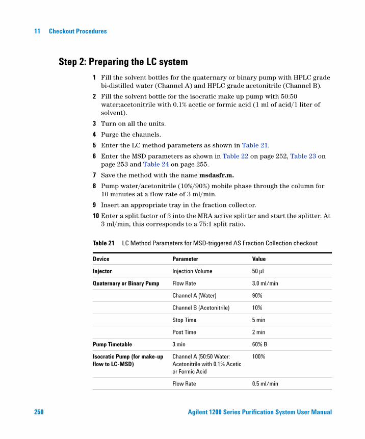
250 Agilent 1200 Series Purification System User Manual
11 Checkout Procedures
Step 2: Preparing the LC system
1 Fill the solvent bottles for the quaternary or binary pump with HPLC grade bi-distilled water (Channel A) and HPLC grade acetonitrile (Channel B).
2 Fill the solvent bottle for the isocratic make up pump with 50:50 water:acetonitrile with 0.1% acetic or formic acid (1 ml of acid/1 liter of solvent).
3 Turn on all the units.
4 Purge the channels.
5 Enter the LC method parameters as shown in Table 21.
6 Enter the MSD parameters as shown in Table 22 on page 252, Table 23 on page 253 and Table 24 on page 255.
7 Save the method with the name msdasfr.m.
8 Pump water/acetonitrile (10%/90%) mobile phase through the column for 10 minutes at a flow rate of 3 ml/min.
9 Insert an appropriate tray in the fraction collector.
10 Enter a split factor of 3 into the MRA active splitter and start the splitter. At 3 ml/min, this corresponds to a 75:1 split ratio.
Table 21 LC Method Parameters for MSD-triggered AS Fraction Collection checkout
Device Parameter Value
Injector Injection Volume 50 μl
Quaternary or Binary Pump Flow Rate 3.0 ml/min
Channel A (Water) 90%
Channel B (Acetonitrile) 10%
Stop Time 5 min
Post Time 2 min
Pump Timetable 3 min 60% B
Isocratic Pump (for make-up flow to LC-MSD)
Channel A (50:50 Water: Acetonitrile with 0.1% Acetic or Formic Acid
100%
Flow Rate 0.5 ml/min
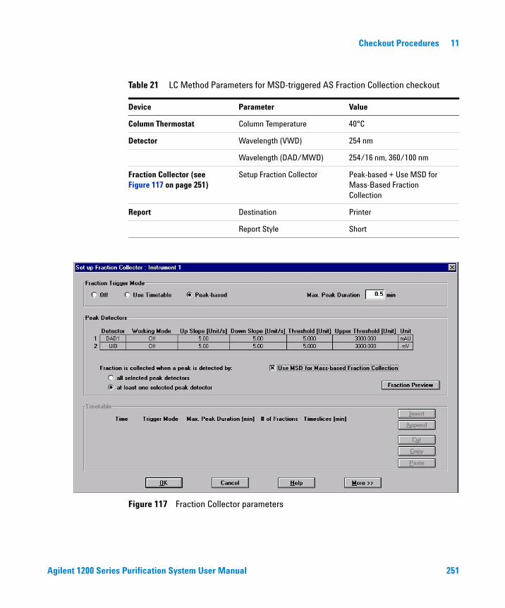
Agilent 1200 Series Purification System User Manual 251
Checkout Procedures 11
Column Thermostat Column Temperature 40°C
Detector Wavelength (VWD) 254 nm
Wavelength (DAD/MWD) 254/16 nm, 360/100 nm
Fraction Collector (see Figure 117 on page 251)
Setup Fraction Collector Peak-based + Use MSD for Mass-Based Fraction Collection
Report Destination Printer
Report Style Short
Figure 117 Fraction Collector parameters
Table 21 LC Method Parameters for MSD-triggered AS Fraction Collection checkout
Device Parameter Value
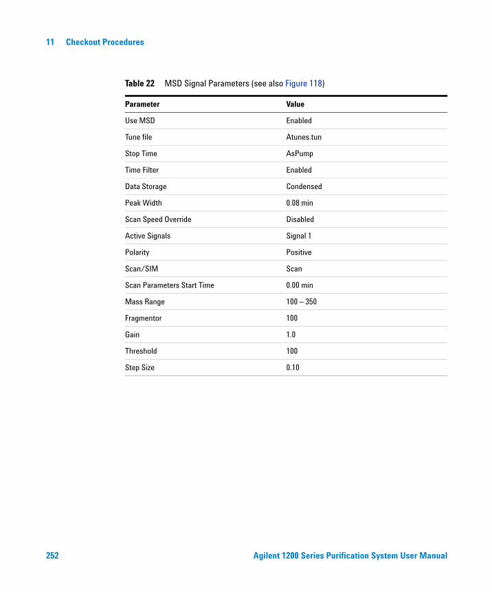
252 Agilent 1200 Series Purification System User Manual
11 Checkout Procedures
Table 22 MSD Signal Parameters (see also Figure 118)
Parameter Value
Use MSD Enabled
Tune file Atunes.tun
Stop Time AsPump
Time Filter Enabled
Data Storage Condensed
Peak Width 0.08 min
Scan Speed Override Disabled
Active Signals Signal 1
Polarity Positive
Scan/SIM Scan
Scan Parameters Start Time 0.00 min
Mass Range 100 – 350
Fragmentor 100
Gain 1.0
Threshold 100
Step Size 0.10
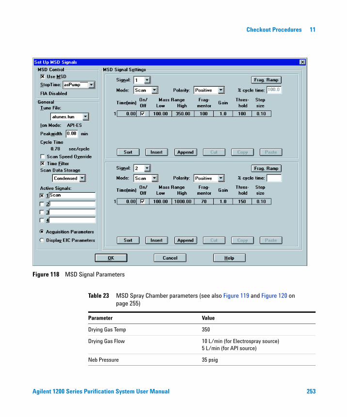
Agilent 1200 Series Purification System User Manual 253
Checkout Procedures 11
Figure 118 MSD Signal Parameters
Table 23 MSD Spray Chamber parameters (see also Figure 119 and Figure 120 on page 255)
Parameter Value
Drying Gas Temp 350
Drying Gas Flow 10 L/min (for Electrospray source)5 L/min (for API source)
Neb Pressure 35 psig
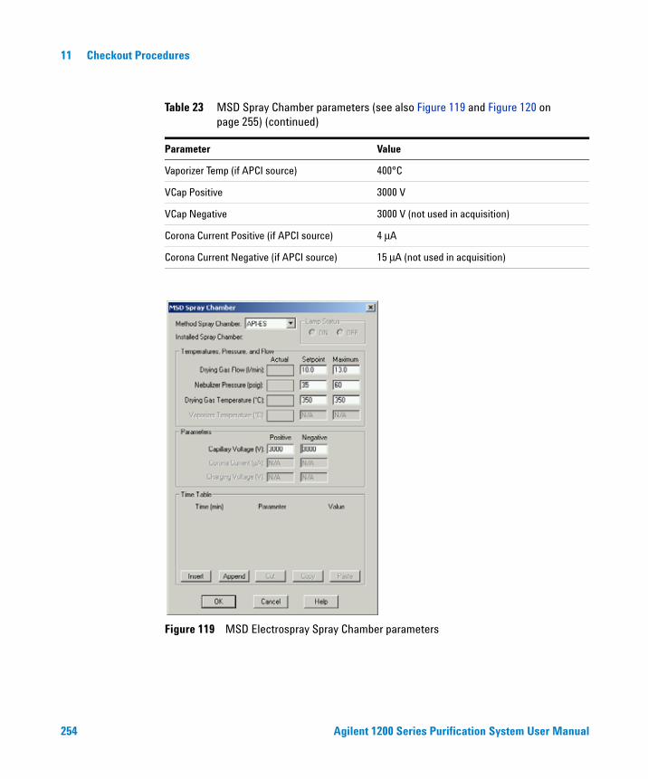
254 Agilent 1200 Series Purification System User Manual
11 Checkout Procedures
Vaporizer Temp (if APCI source) 400°C
VCap Positive 3000 V
VCap Negative 3000 V (not used in acquisition)
Corona Current Positive (if APCI source) 4 μA
Corona Current Negative (if APCI source) 15 μA (not used in acquisition)
Figure 119 MSD Electrospray Spray Chamber parameters
Table 23 MSD Spray Chamber parameters (see also Figure 119 and Figure 120 on page 255) (continued)
Parameter Value
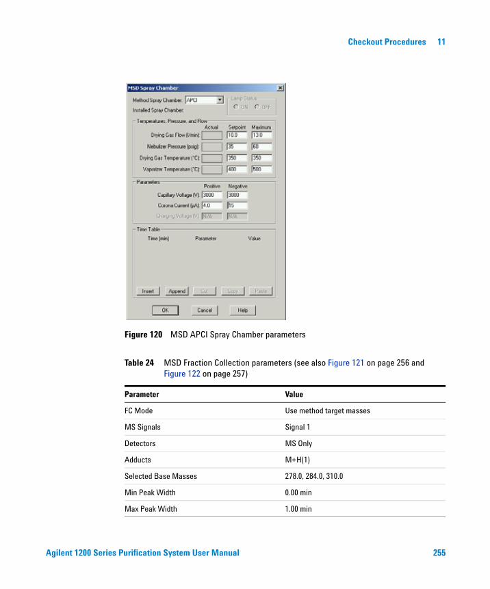
Agilent 1200 Series Purification System User Manual 255
Checkout Procedures 11
Figure 120 MSD APCI Spray Chamber parameters
Table 24 MSD Fraction Collection parameters (see also Figure 121 on page 256 and Figure 122 on page 257)
Parameter Value
FC Mode Use method target masses
MS Signals Signal 1
Detectors MS Only
Adducts M+H(1)
Selected Base Masses 278.0, 284.0, 310.0
Min Peak Width 0.00 min
Max Peak Width 1.00 min
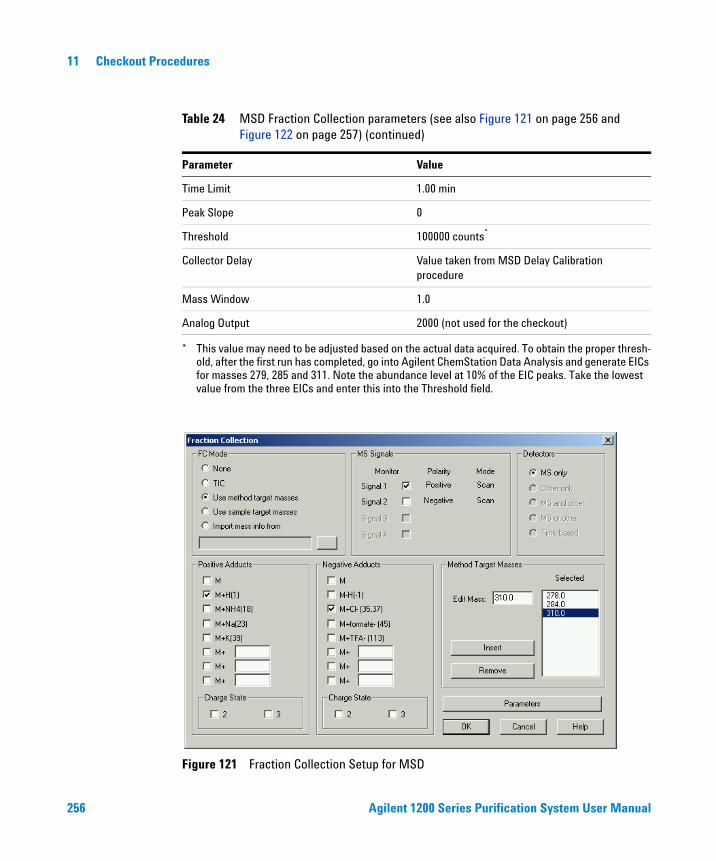
256 Agilent 1200 Series Purification System User Manual
11 Checkout Procedures
Time Limit 1.00 min
Peak Slope 0
Threshold 100000 counts*
Collector Delay Value taken from MSD Delay Calibration procedure
Mass Window 1.0
Analog Output 2000 (not used for the checkout)
* This value may need to be adjusted based on the actual data acquired. To obtain the proper thresh-old, after the first run has completed, go into Agilent ChemStation Data Analysis and generate EICs for masses 279, 285 and 311. Note the abundance level at 10% of the EIC peaks. Take the lowest value from the three EICs and enter this into the Threshold field.
Figure 121 Fraction Collection Setup for MSD
Table 24 MSD Fraction Collection parameters (see also Figure 121 on page 256 and Figure 122 on page 257) (continued)
Parameter Value
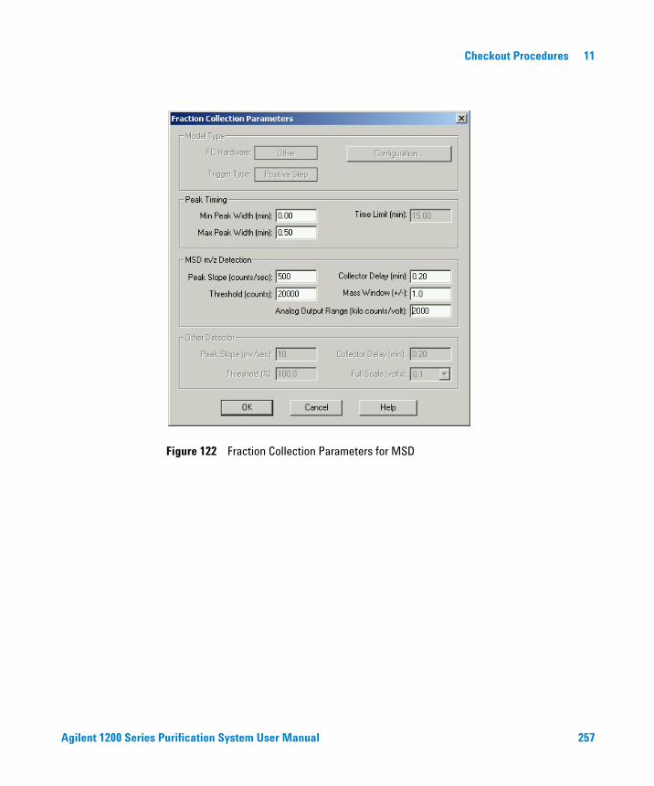
Agilent 1200 Series Purification System User Manual 257
Checkout Procedures 11
Figure 122 Fraction Collection Parameters for MSD
258 Agilent 1200 Series Purification System User Manual
11 Checkout Procedures
Step 3: Running the Checkout Method
1 From the Agilent ChemStation RunControl menu, select Sample Info…, then select manual data file name, and enter the data file name 'msaschk1.d', then specify the appropriate vial location for the checkout sample, then click Run Method.
Step 4: Review Results
1 When the checkout method run is finished, verify that you have three fractions collected in the vials, wells or tubes.
2 Verify that you have three fractions indicated on the MSD TIC in the Agilent ChemStation report or in Agilent ChemStation Data Analysis (see Figure 123 on page 259).
3 If you have not successfully collected the three fractions corresponding to the three peaks, evaluate the data file in Agilent ChemStation Data Analysis for the proper threshold triggering level. Update the threshold value in the MSD Fraction Collection Parameters dialog box, and rerun the checkout.
NOTE The checkout sample contains four components, but you will probably get separation into only three peaks — two of the compounds will co-elute.
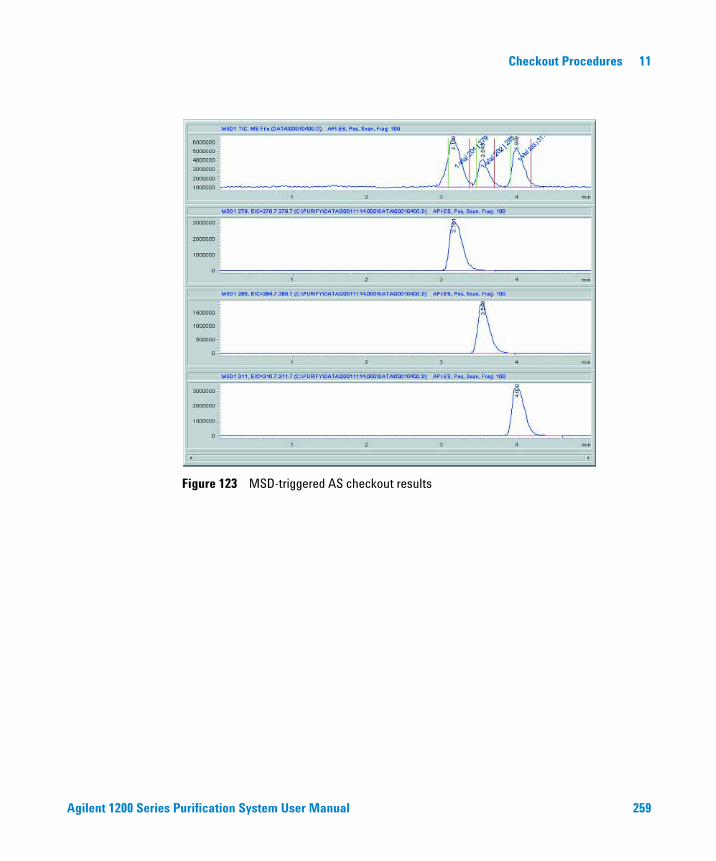
Agilent 1200 Series Purification System User Manual 259
Checkout Procedures 11
Figure 123 MSD-triggered AS checkout results

260 Agilent 1200 Series Purification System User Manual
11 Checkout Procedures
Step 5: Reanalyze Fraction #2
1 Reanalyze the fraction that was collected in the second vial, well or tube using the same conditions used for the checkout method msdasfr.m, but with the Use MSD for Mass-Based Fraction Collection deselected in the Setup Fraction Collector dialog box. Save the method as msdrean1.m.
2 You should see only one peak in the chromatogram of the reanalyzed fraction. If you do not see the peak in the TIC, generate EICs for masses 279, 285, and 311 and verify that there is a single peak in one of the EICs (see Figure 124).
Figure 124 EICs after reanalysis of fraction 2
Agilent 1200 Series Purification System User Manual 261
Checkout Procedures 11
MSD-triggered PS Fraction Collection Checkout
The checkout procedure consists of the following activities:
• Preparing the Agilent 1200 Series LC and LC/MSD
• Setting the checkout method parameters
• Running the checkout and collecting fractions
• Reviewing the results and reanalyzing a fraction
What you will need
Instruments
• Agilent 1200 Series Preparative Autosampler (optional thermostatted version).
• Two Agilent 1200 Series Preparative Pumps used in a binary pump configuration
• Agilent 1200 Series Isocratic Pump with solvent bottle to be used as the make-up pump for the LC/MSD.
• Agilent 1200 Series Fraction Collector Preparative Scale (optional thermostatted version)
• Agilent 1200 Series LC/MSD (G1946B,C, or G1956A,B)
• G1968C Mass-Based Fraction Collection Kit
Software
• Agilent LC/MSD ChemStation Software (G2710AA) rev. B.01.01 or higher
Column
• Zorbax SB-C18, 9.4 mm x 5.0 cm, 5um (part number 846975-202, included in G1968C mass-based fraction collection kit)
262 Agilent 1200 Series Purification System User Manual
11 Checkout Procedures
Solvents
• HPLC grade Bi-distilled water
• HPLC grade Acetonitrile
• Acetic or Formic acid
Sample
• Delay calibrant (part number G1946-85020, included in G1968C mass-based fraction collection kit)
• Electrospray LC Demo Sample (part number 59987-20033, included in G1968C mass-based fraction collection kit)
Step 1: Calibrating the Delay Time
Before running the fraction collection, the delay time between the MSD detector and the fraction collector must be determined. See “Delay Volume Calibration” on page 93 for the procedure to determine the delay time. This value is entered into the MSD Fraction Collection Parameters panel. For the delay calibration method, specify an LC flow of 10.0 ml/min, and a make-up pump flow of 0.5 ml/min.
Agilent 1200 Series Purification System User Manual 263
Checkout Procedures 11
Step 2: Preparing the LC system
1 Fill the solvent bottles for the Preparative pumps with HPLC grade bi-distilled water (Channel A) and HPLC grade acetonitrile (Channel B).
2 Fill the solvent bottle for the isocratic make-up pump with 50:50 water:acetonitrile with 0.1% acetic or formic acid (1 ml of acid/1 liter of solvent).
3 Turn on all the units.
4 Purge the channels.
5 Enter the LC methods as shown in Table 25.
6 Enter the MSD parameters as shown in Figure 26 on page 265, Figure 27 on page 266 and Figure 28 on page 268.
7 Save the method with the name msdpsfr.m.
8 Pump water/acetonitrile (10%/90%) mobile phase through the column for 10 minutes at a flow rate of 10 ml/min.
9 Insert an appropriate tray in the fraction collector.
10 Enter a split ratio of 3 into the MRA active splitter and start the splitter. At 10 ml/min, this corresponds to a 250:1 split ratio.
Table 25 LC Method Parameters for MSD-triggered PS Fraction Collection checkout
Device Parameter Value
Injector Injection Volume 50 μl
Quaternary or Binary Pump Flow Rate 10.0 ml/min
Channel A (Water) 90%
Channel B (Acetonitrile) 10%
Stop Time 5 min
Post Time 2 min
Pump Timetable 3 min 60% B
Isocratic Pump (for make-up flow to LC-MSD)
Channel A (50:50 Water: Acetonitrile with 0.1% Acetic or Formic Acid
100%
Flow Rate 0.5 ml/min
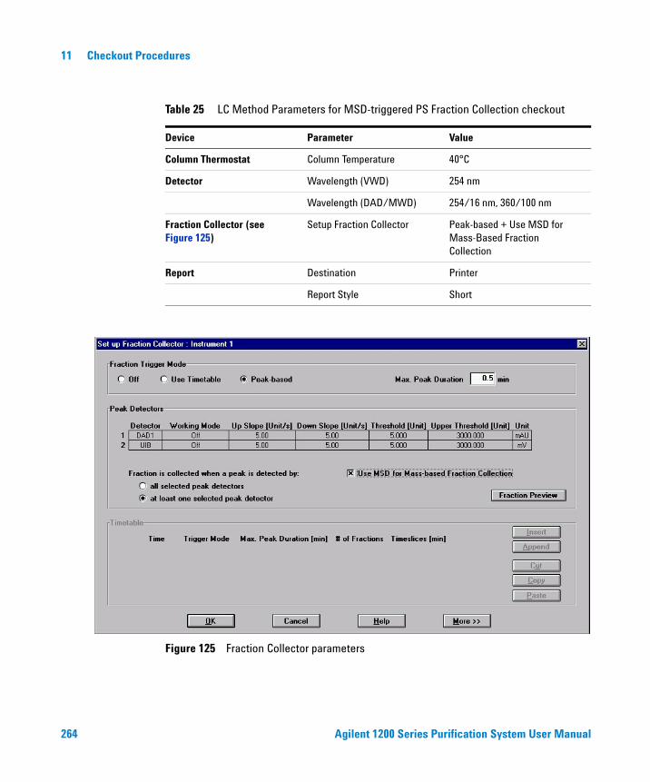
264 Agilent 1200 Series Purification System User Manual
11 Checkout Procedures
Column Thermostat Column Temperature 40°C
Detector Wavelength (VWD) 254 nm
Wavelength (DAD/MWD) 254/16 nm, 360/100 nm
Fraction Collector (see Figure 125)
Setup Fraction Collector Peak-based + Use MSD for Mass-Based Fraction Collection
Report Destination Printer
Report Style Short
Figure 125 Fraction Collector parameters
Table 25 LC Method Parameters for MSD-triggered PS Fraction Collection checkout
Device Parameter Value

Agilent 1200 Series Purification System User Manual 265
Checkout Procedures 11
Table 26 MSD Signal Parameters (see also Figure 126)
Parameter Value
Use MSD Enabled
Tune file Atunes.tun
Stop Time AsPump
Time Filter Enabled
Data Storage Condensed
Peak Width 0.08 min
Scan Speed Override Disabled
Active Signals Signal 1
Polarity Positive
Scan/SIM Scan
Scan Parameters Start Time 0.00 min
Mass Range 100 – 350
Fragmentor 100
Gain 1.0
Threshold 100 (adjust as appropriate to eliminate spectral noise)
Step Size 0.10
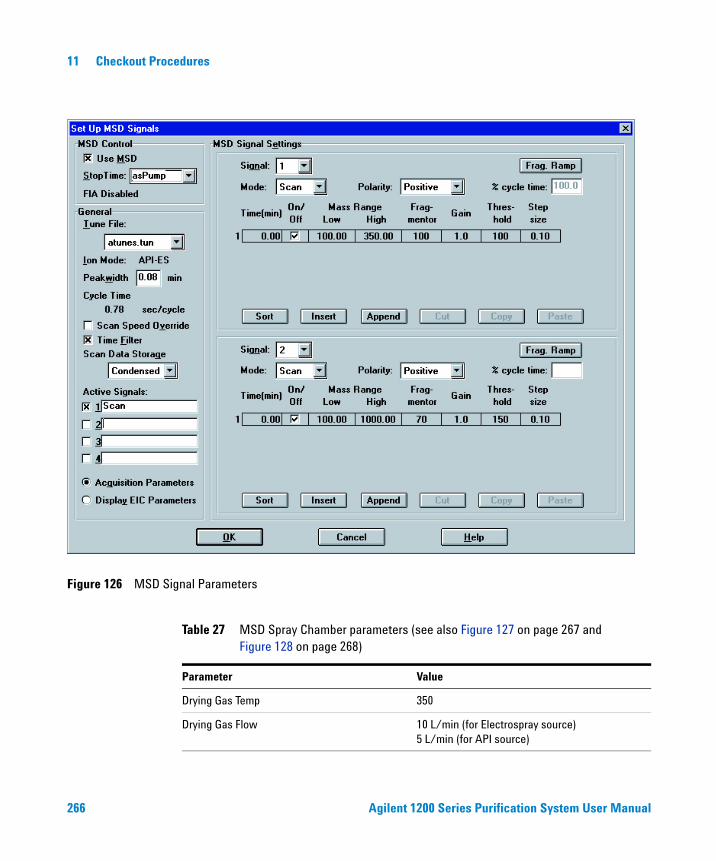
266 Agilent 1200 Series Purification System User Manual
11 Checkout Procedures
Figure 126 MSD Signal Parameters
Table 27 MSD Spray Chamber parameters (see also Figure 127 on page 267 and Figure 128 on page 268)
Parameter Value
Drying Gas Temp 350
Drying Gas Flow 10 L/min (for Electrospray source)5 L/min (for API source)
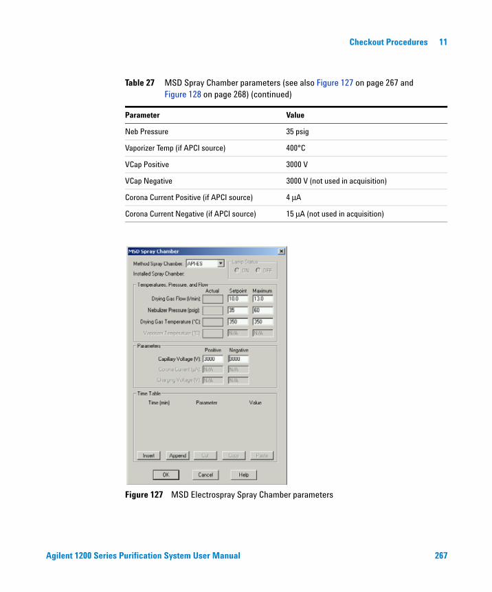
Agilent 1200 Series Purification System User Manual 267
Checkout Procedures 11
Neb Pressure 35 psig
Vaporizer Temp (if APCI source) 400°C
VCap Positive 3000 V
VCap Negative 3000 V (not used in acquisition)
Corona Current Positive (if APCI source) 4 μA
Corona Current Negative (if APCI source) 15 μA (not used in acquisition)
Figure 127 MSD Electrospray Spray Chamber parameters
Table 27 MSD Spray Chamber parameters (see also Figure 127 on page 267 and Figure 128 on page 268) (continued)
Parameter Value
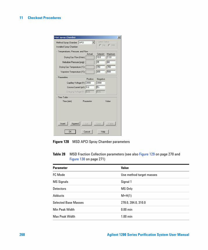
268 Agilent 1200 Series Purification System User Manual
11 Checkout Procedures
Figure 128 MSD APCI Spray Chamber parameters
Table 28 MSD Fraction Collection parameters (see also Figure 129 on page 270 and Figure 130 on page 271)
Parameter Value
FC Mode Use method target masses
MS Signals Signal 1
Detectors MS Only
Adducts M+H(1)
Selected Base Masses 278.0, 284.0, 310.0
Min Peak Width 0.00 min
Max Peak Width 1.00 min

Agilent 1200 Series Purification System User Manual 269
Checkout Procedures 11
Time Limit 1.00 min
Peak Slope 0
Threshold 100000 counts*
Collector Delay Value taken from NMSD Delay Calibration procedure
Mass Window 1.0
Analog Output 2000 (not used for the checkout)
* This value may need to be adjusted based on the actual data acquired. To obtain the proper thresh-old, after the first run has completed, go into ChemStation Data Analysis and generate EICs for masses 279, 285 and 311. Note the abundance level at 10% of the EIC peaks. Take the lowest value from the three EICs and enter this into the Threshold field.
Table 28 MSD Fraction Collection parameters (see also Figure 129 on page 270 and Figure 130 on page 271) (continued)
Parameter Value
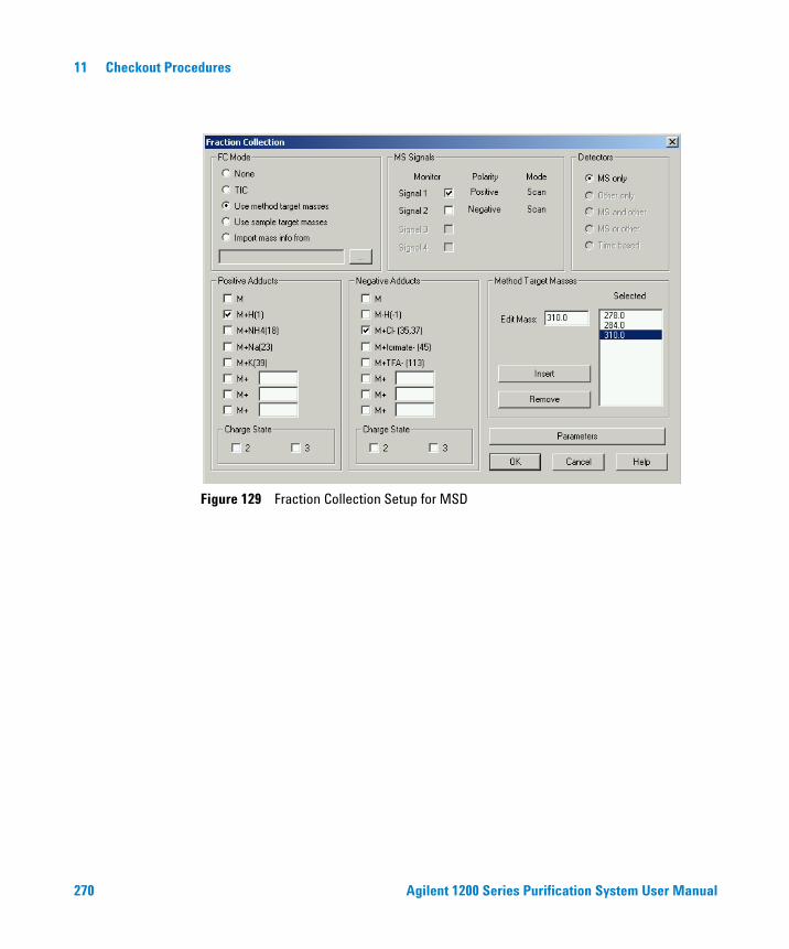
270 Agilent 1200 Series Purification System User Manual
11 Checkout Procedures
Figure 129 Fraction Collection Setup for MSD
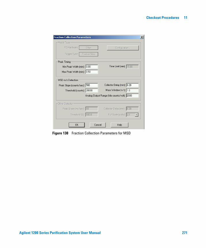
Agilent 1200 Series Purification System User Manual 271
Checkout Procedures 11
Figure 130 Fraction Collection Parameters for MSD
272 Agilent 1200 Series Purification System User Manual
11 Checkout Procedures
Step 3: Running the Checkout Method
1 From the Agilent ChemStation RunControl menu, select Sample Info…, then select manual data file name, and enter the data file name 'mspschk1.d', then specify the appropriate vial location for the checkout sample, then click Run Method.
Step 4: Review Results
1 When the checkout method run is finished, verify that you have three fraction collected in the vials, wells or tubes.
2 Verify that you have three fractions indicated on the MSD TIC in the ChemStation report or in Agilent ChemStation Data Analysis. (see Figure 131 on page 273).
3 If you have not successfully collected the three fractions corresponding to the three peaks, evaluate the data file in Agilent ChemStation Data Analysis for the proper threshold triggering level. Update the threshold value in the MSD Fraction Collection Parameters dialog box, and rerun the checkout.
NOTE The checkout sample contains four components, but you will probably get separation into only three peaks — two of the compounds will co-elute.)
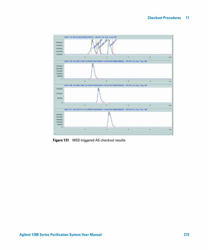
Agilent 1200 Series Purification System User Manual 273
Checkout Procedures 11
Figure 131 MSD-triggered AS checkout results
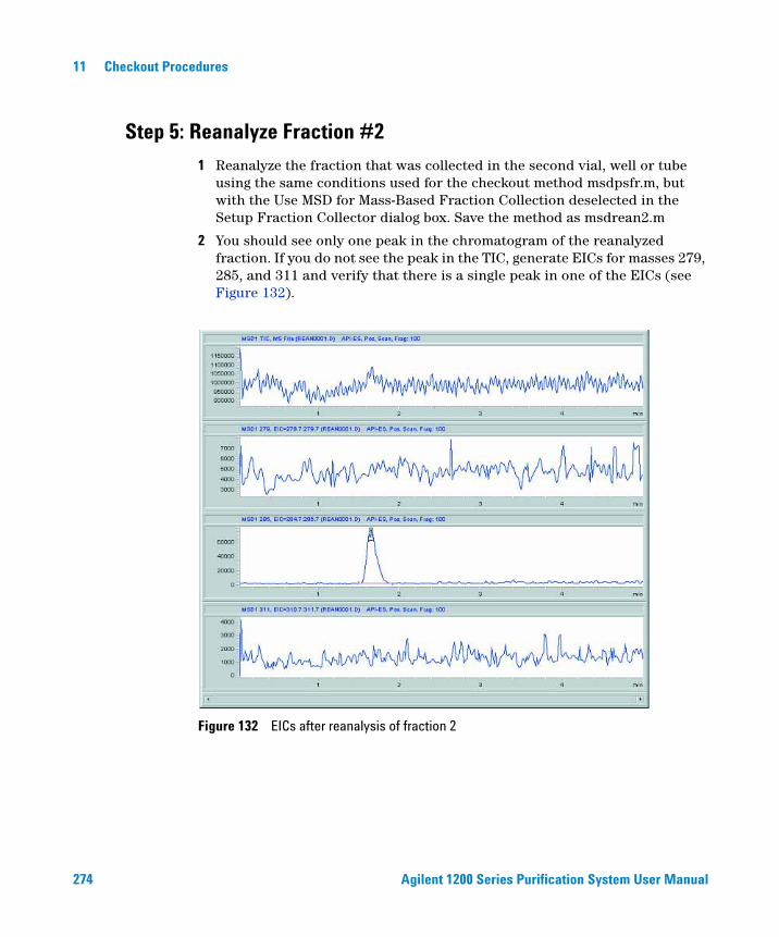
274 Agilent 1200 Series Purification System User Manual
11 Checkout Procedures
Step 5: Reanalyze Fraction #2
1 Reanalyze the fraction that was collected in the second vial, well or tube using the same conditions used for the checkout method msdpsfr.m, but with the Use MSD for Mass-Based Fraction Collection deselected in the Setup Fraction Collector dialog box. Save the method as msdrean2.m
2 You should see only one peak in the chromatogram of the reanalyzed fraction. If you do not see the peak in the TIC, generate EICs for masses 279, 285, and 311 and verify that there is a single peak in one of the EICs (see Figure 132).
Figure 132 EICs after reanalysis of fraction 2
Agilent 1200 Series Purification System User Manual 275
Index
Numerics35900E, 28
AA/D-Converter, 28abort, 126aborting a study, 173active flow splitter, 29actual fill volume, 177adapter
air channel, 32adding samples, 149adducts, 86air channel adapter, 32air circulation, 15altitude
non-operating, 18operating, 18
ambient non-operating temperature, 18ambient operating temperature, 18analog output range, 92analog signal delay, 115analytical scale system configuration, 21annotation
fractions, 202assigning methods, 150automatic delay volume reduction, 64autosampler, 57auxiliary, 74available methods, 151
Bbase path
study, 136baseline drift, 71
bench space, 15bottom sensing, 65, 66bypass, 64
Ccable
CAN, 28connecting APG remote, 23, 26connecting CAN, 23, 26connecting GPIB, 23, 26connecting LAN, 23, 26connecting the ChemStation, 23, 26connecting the power, 23, 26connections, 30, 33power, 28thermostat interconnection, 32
cabling, 34calculation
delay volume, 112calibration
delay volume, 93CAN cable, 28CAN-DC-IN, 28CAN-DC-OUT, 28capillaries, 34carry-over, 64, 66channel
plug, 32ChemStation
report, 144, 202software, 42
ChemStore, 42, 141chromatogram, 145close study, 125closing a study, 167
collectionmode, 69order, 69
collector delay, 91column
sequence, 124width, 123
condensation, 18configuration
analytical scale system, 21fraction collector, 67injector, 57multi-instrument, 43multiple fraction collectors, 76preparative scale system, 24stack, 20well-plate types, 54
configurations, 42connections
cable, 30, 33flow, 34
considerations, 14continuous flow collection, 69corrugated waste tube, 31cross-contamination, 69CSV, 205CSV file, 146, 158, 161current study, 121
Ddamaged packaging, 19data file name, 155, 180, 214data folder, 213data view panels, 185
276 Agilent 1200 Series Purification System User Manual
Index
delay volume, 64, 69calculations, 112calibration, 93
delay volume reductionautomatic, 64
deletinginjections, 163samples, 163study, 164
delivery checklist, 19description
study, 142detection parameters, 72detector peakwidth, 93, 98, 112, 114detectors, 86
peak, 72dimensions, 17
well-plate, 54directory structure, 212discrete fraction collection, 69downslope, 71, 73drainage
waste, 28draw
position, 63, 64, 66speed, 63, 64, 66
Dual loop autosampler, 65
Eedit menu, 126eject speed, 63, 64, 66electrical connections
thermostat, 33environment, 14, 18equilibration time, 64, 66Existing Study, 140Exit, 126explorer, 121Export, 125export to CSV, 205Exporting, 160
Ffile menu, 125filling information, 177flow connections, 34
analytical scale system, 36preparative scale system, 38
flow ratemaximum, 114
flow splitter, 29flush-out factor, 64, 66
sample, 64flushport, 64, 66format
sample name, 142fraction
annotation, 202list, 209start position, 153table, 203trigger mode, 71
fraction collection, 143enabled, 77mass-based, 77mode, 81parameters, 88peak-based, 71time, 72time-based, 72
fraction collectorconfiguration, 67order, 75panel, 122, 153, 187setup, 70
fraction collectorsmultiple, 35, 75
Fraction Controller Panel, 128fraction delay sensor, 93Fraction Preview, 73frequency, 18fuses, 14
GG1160A, 28, 35
G1310A, 29G1390A, 28G1968C, 28graphical reporting, 204graphics
multiple, 145
Hhardware, 42height
tube, 68Help, 130help menu, 130hotspot, 190, 191HUB, 29humidity, 18
IImporting, 159information
sample, 150study, 141
injectionorder, 142overlap, 64, 66parameters, 151status, 155type, 62, 64, 65
injection volume, 62, 64, 155maximum, 58, 60, 61
injectionsdeleting, 163
injectorconfiguration, 57program, 62, 64, 65setup, 61
installation, 44installed trays, 58, 60, 61, 68Installing, 27installing a thermostatted module
interface cables, 31power cable, 31safety, 31
Agilent 1200 Series Purification System User Manual 277
Index
installing the Purification Systeminterface cables, 27power cable, 27safety, 27
installing the purification systemflow connections, 34
installing the thermostatted fraction collector
preparation, 31installing the thermostatted Purification
Systemsafety, 27
inteface boardLAN, 27
interactive report, 201interconnection cable
thermostat, 32into location, 69
LLAN interface board, 27LC/CE ChemStation, 42LC/MSD ChemStation, 42LC-MSD, 28license, 43, 46, 49, 144line
frequency, 18voltage, 18
locationsreserved, 69sample, 148
Mmainpass, 64make-up-pump, 29mass
window, 92mass based fraction collection
kit, 28mass-based fraction collection, 77masses
target, selected, 87
maximumflow rate, 114injection volume, 58, 60, 61peak width, 89volume, 74
maximum flow rates, 114maximum peak duration, 71menu
bar, 125purify, 47
method, 155, 176parameters, 176source path, 137
Method Source Path, 129method target masses, 87methods
assigning, 150available, 151
minimum peak width, 89missing parts, 19missing peaks, 114mode
fraction collection, 81fraction trigger, 71
modifyingstudy, 167
molecularformula, 161weight, 161
more, 74MS signals, 85MSD m/z detection, 90multi-instrument configuration, 43multiple draw, 58multiple fraction collectors, 35, 75
configuration, 76setup, 76
multiple graphics, 145
Nname
data file, 155, 180operator, 141sample, 155study, 139
name formatsample, 142
needlemovement, 69position, 69rinse, 74wash, 62, 64, 65
new study, 125, 139new study run, 168non-operating altitude, 18non-operating temperature, 18number
of fractions, 72of pools, 143
Ooffline software, 44online software, 44online tickmarks, plot, 175open study, 125opening a study, 165operating altitude, 18operating systems, 42operating temperature, 18operator name, 141Options, 129options menu, 129order
fraction collector, 75injection, 142
overlap injection, 64, 66cycle, 63
Ppackaging
damaged, 19
278 Agilent 1200 Series Purification System User Manual
Index
parametersfraction collection, 88injection, 151method, 176peak detection, 72pooling, 181study, 123, 141, 182, 185
partial study, 156, 168, 172parts and materials, 19path
method, 137study, 136
pause, 126pause study, 126pausing a study, 173peak
detection parameters, 72detectors, 72slope, 90timing, 89
peak duration, 71peak width, 93, 98, 112, 114
maximum, 89minimum, 89
peak-based fraction collection, 71peakwidth, 115physical specifications, 18plug channel, 32plumbing, 34pooling, 180
parameters, 181properties, 182
poolsnumber, 143
positionneedle, 69
post-time, 74power
cable, 28consumption, 18cords, 15requirements, 14switch, 28
power cords, 15
preconfigured well-plate types, 53prefetch sample vial, 63preparative scale system configuration, 24prerequisites, 52preview, 73
report, 201properties
pooling, 182pump
make-up, 29purification/hi throughput
reports, 205software, 43
purify menu, 47purity, 43purity calculation, 43
Qqualifier level, 151
Rrate, 115recovery, 143recovery fraction collector, 75recovery location, 155, 156regional settings, 42report
ChemStation, 144, 202interactive, 201preview, 201specification, 144specify, 125
reprocess a study, 172, 176reserved locations, 69response time, 115Result Panel, 129result panel, 123, 191results
study, 175review study data, 184rinse fraction collector needle, 74rinse needle, 74
Run Control, 126run control, 172
menu, 126
Ssafety standards, 18sample
description, 155flush-out factor, 64information, 150list, 208location, 148, 155name, 155name format, 142
Sampler Panel, 128sampler panel, 122, 148, 186samples
adding, 149deleting, 163
save study, 125saving a study, 164seat capillary volume, 58, 60, 61Select Mode, 128select mode, 120selected masses, 87setup
fraction collector, 70injector, 61more, 74multiple fraction collectors, 76
Setup Result Panel, 129Show Fraction Scheme, 128show fraction scheme, 187Show Messages, 129site requirements, 14slope, 72snapshot, 175software
ChemStation, 42purification/hi-throughput, 43
spacebench, 15
Agilent 1200 Series Purification System User Manual 279
Index
specificationreport, 144
specificationsdimensions, 17physical, 18weight, 16
specify report, 125splitter
flow, 29spreadsheet, 158, 162stack configuration, 20, 21, 22, 23, 24, 25,
26front view, 21, 22, 24, 25rear view, 23, 26
standard autosampler, 57standards
safety, 18start location, 143
recovery, 143start study, 126starting a study, 172status
injection, 155study, 174, 177
status info, 126stop study, 126stop time, 74stopping a study, 173storage, 18
study, 136aborting, 173base path, 136close, 125closing, 167deleting, 164description, 142editor, 138information, 141list, 122, 123, 136, 140, 155, 158, 188modifying, 167name, 139new, 125, 139open, 125opening, 165parameters, 123, 136, 141, 182, 185partial, 168, 172pause, 126pausing, 173reprocess, 172reprocessing, 176results, 175review, 184save, 125saving, 164start, 126starting, 172status, 174, 177stop, 126stopping, 173
Study Base Path, 129Study List (Fraction Wells), 128study list (fraction wells), 190Study List (Injections), 128study list (injections), 189Study List (Samples), 128study run summary, 207Study Wizard, 146study wizard, 139supported configurations, 42supported operating systems, 42switch
power, 28syringe volume, 58
system configurationanalytical scale, 21preparative scale, 24
Ttarget mass, 151target masses, 87temperature, 18
non-operating, 18operating, 18
test tube tray, 68thermostat
electrical connections, 33thermostat interconnection cable, 32threshhold, 71, 72, 73, 91thumbnail, 145, 204tickmarks, 175time limit, 90time-based fraction collection, 72timetable, 71, 72toolbar, 131tree view, 121trigger mode, 71, 73
fraction, 71trigger parameters, 73trigger type, 88triggering, 72tube
height, 68volume, 68waste, 31
UUIB, 28uninstall, 49universal interface box, 28unpacking modules, 19upper threshhold, 71, 73upslope, 71, 73user-configured well-plate types, 54
280 Agilent 1200 Series Purification System User Manual
Index
Vvessel filling volume, 177view
menu, 128mode, 120
View Mode, 128viewing data in ChemStation, 196voltage, 18volume
delay, 69injection, 62, 64, 155maximum, 74maximum injection, 58, 60, 61seat capillary, 58, 60, 61syringe, 58tube, 68vessel, tray, 177
Wwash
needle, 62, 64, 65vial, 62, 64, 66
wastedrainage, 28tube, 31
weight, 15weight specifications, 16well-plate, 60, 61, 69
dimensions, 54well-plate types, 53
configuring, 54preconfigured, 53user-configured, 54
Window, 129window menu, 129wizard, 139working mode, 71, 72workspace, 121

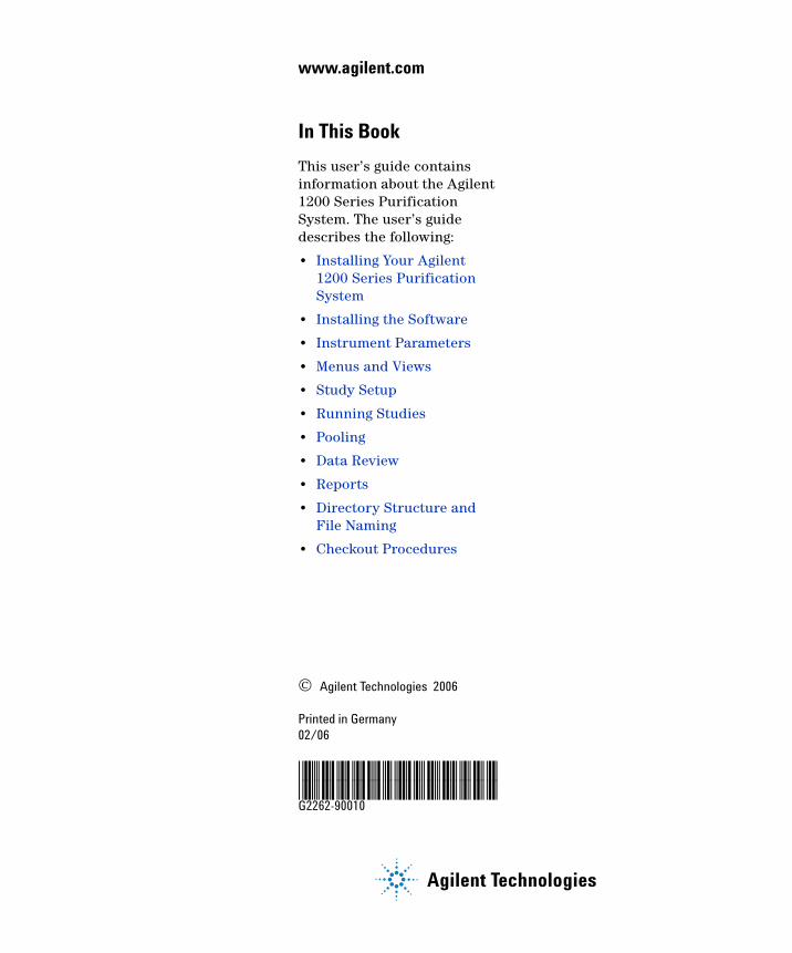
© Agilent Technologies 2006
Printed in Germany 02/06
*G2262-90010**G2262-90010*G2262-90010
www.agilent.com
Agilent Technologies
In This Book
This user’s guide contains information about the Agilent 1200 Series Purification System. The user’s guide describes the following:
• Installing Your Agilent 1200 Series Purification System
• Installing the Software
• Instrument Parameters
• Menus and Views
• Study Setup
• Running Studies
• Pooling
• Data Review
• Reports
• Directory Structure and File Naming
• Checkout Procedures