print layout 1 - gemslgemsl.com/pdf/downstream/rotoflow_turboexpander generator_catalo… · the...
TRANSCRIPT

Turboexpander-Generators for Natural Gas Applications
GE EnergyOil & Gas

3
The first turboexpander application for natural gas processing wasaccomplished using Rotoflow technology in Texas in the early 1960s.It dramaticallly demonstrated how efficiently the expansion turbinecould condense heavier components of the gas stream, while at thesame time providing power to re-compress the leaner gas.
The current range of Rotoflow Turboexpander-Generators grew fromthat original application. Forty years later, close to 4,000 units are inoperation around the world, and Rotoflow has proven, many timesover, its ability to engineer machinery that delivers higher power levels,functions at extreme operating temperatures, and achieves greaterpressure ratios. Our turboexpander experience and technology havebecome invaluable resources for every segment of the natural gasand hydrocarbon industries.
The rapid growth of Rotoflow turboexpander technology has been astory of continuous improvement in expander design, rotor and bearingdesign, efficiency optimization, and control systems. This growth hasbeen driven by the needs of the industry to increase capacity, reducecosts, and maximize reliability. By adopting an internal business structurethat parallels the structure of the oil and gas industry, GE Energy is ableto address those needs directly, as an active partner in the search formore effective solutions.
Four of GE Energy’s Oil & Gas Business Units are closely involved in theapplication of Turboexpander-Generator solutions for natural gas andrelated processes.
Upstream Natural Gas Liquids letdown and Liquefied Petroleum Gas recovery;Ethane recovery.
Midstream Merging of pipelines with different pressures.
Downstream Hydrogen purification; Recovery of heavier components from tail gas;Power recovery from gas streams; Geothermal power generation;Ethylene production; Gas-to-liquids production.
Industrial PlantsIndustrial Plants, integrates Turboexpander-Generators into plant designs.
Global ServicesA fifth business unit , Global Services, provides expert installation,pre-commissioning and start-up services for new turboexpanderinstallations. Global Services also provides maintenance and repairservices on a scheduled or on-call basis, and will convert , modifyand uprate machinery to meet changing production targets.
The Center of Excellence concept enables GE Energy to deliver innovativesolutions to its Oil & Gas customers worldwide, and to support themin their efforts to achieve the highest productivity and efficiencythroughout the life of their GE equipment.
The GE Turboexpander Center of Excellence brings together specialistsin design, manufacturing and testing to ensure continuing improvementin technology and to develop unique, application specific, solutions toour customers’ special needs. Close co-operation between customercontact teams familiar with the challenges and objectives of the industrysegment they serve, and design engineers who have an unmatchedunderstanding of every aspect of turboexpander technology andoperation, guarantees that Rotoflow applications provide exceptionalquality, reliability and long-term value to the user.
Advanced manufacturing resourcesIn order to achieve synergies of size and specialization GE Energy hasbrought together manufacturing of a wide range of precision machineryfor the oil and gas industry at a new facility in Oshkosh, Wisconsin.Among products which benefit from this integrated approach are abroad range of compressors of many types as well as the full rangeof Rotoflow Turboexpanders.
Advantages to users include faster turnaround, economies in coststhrough strategic sourcing, and a steady increase in quality andperformance as Six Sigma, the quality control methodology usedthroughout the GE organization, is focussed on eliminating defectsand adding value to every product and service we offer.
Advanced testing proceduresOur modern test facilities provide us with the capabilities required toevaluate new concepts under development, validate new computer-aideddesign tools, and test products before they are shipped to customers.Our facilities enable us to perform full load tests and include feed gaspreparation systems which allow us to test using virtually any gasmixture of interest to a customer.
Our test facilities are completely instrumented and furnished with realtime data acquisition systems integrated with analysis tools to providea complete map of the equipment’s performance.
Rotoflow turboexpanders are normally tested with low pressure air in anopen loop set up in accordance with ASME PTC10, Class II/III. With theGE Energy test facilities, Rotoflow turboexpanders can also be testedat full load and speed with mixtures of nitrogen and helium to satisfyASME PTC10, Class I. In 2004, we performed a full load/speed test ofa turboexpander along with a Nuovo Pignone compressor for a plantin Qatar.
ContentsIntroduction – Turboexpander-Generators and the Natural Gas Industry 3GE Center of Excellence for Design and Testing of Turboexpanders 3Design and Performance Features 4Standard Configurations 6Machinery Layout 8Energy Recovery Applications for Rotoflow Turboexpander-Generators 10
GE Energy has achieved a leadership position in theinternational Oil & Gas industry through constantimprovements in the technology and effectiveness of itssolutions. GE Global Research facilities in North Americaand in Europe develop breakthrough technology innovations,while GE Centers of Excellence, worldwide, put theseadvances to work on behalf of customers.
GE Energy is nearly unique in its ability to provide integratedsolutions to every sector of the industry, from wellhead toconsumer. This network of talented, dedicated, people andresourceful innovators has been responsible for many ofthe most significant industry achievements over the pasthundred years. The development of the turboexpander inthe 1960s and subsquent innovations is just one exampleof the GE contribution to technological advancement in theoil and gas and related industries.
Turboexpander-Generators and the Natural Gas Industry
GE Center of Excellence for Design andTesting of Turboexpanders
A GE Energy test facility.

54
Automatic thrust load control keeps rotor axially centered Variations in axial thrust can result in thrust overloads in turboexpanders.These axial overloads can be induced by the process, by off-designoperation, and by unforeseen transient process conditions. Patentedthrust-load control systems in Rotoflow Turboexpanders automaticallycompensate for these conditions and stabilize axial thrust.
Each thrust bearing is equipped with a pressure tap that senses thethrust load (see cutaway on this page). The pressure at each of the twoopposing thrust bearings is monitored. If the two readings are out ofbalance a controller automatically adjusts the pressure behind theexpander wheel and ensures that the rotor remains centered betweenthe bearings at all times.
Patented oil lubricated bearingsRotoflow patented combination journal and thrust bearings are used tosupport the expander shaft for expander-external gear arrangements.Compared with conventional tilting pad bearings this robust designprovides increased allowance for wear, and delivers nearly nine timesgreater oil spring strength. This exceptional stiffness ensures that thereis no oil whirl (half-speed gyration) or oil film resonance over the entireoperating range of speed and flow.
The spiral grooves on the thrust bearings produce a strong hydrodynamiceffect for high load-bearing capability. The exceptional strength ofthe bearings reduces sensitivity to rotor imbalance caused by dustaccumulation or wear, and increases the ability to withstand depositson the wheels, such as ice or solid CO2.
Complete and user-friendly instrumentation and controlRotoflow Turboexpander-Generators are equipped with integratedexpander instrumentation systems and controls, in a compact package.All systems meet the highest industrial standards, and are fully compliantwith the appropriate national and international statutory codes. Eachsystem is customized according to the requirements of the application,and features protective controls.
Control packages are available with programmable logic control (PLC)systems, and with a human-machine interface (HMI) graphic display forgreater ease of use. PLC control units may be mounted in free-standingcabinets or inside local gauge boards. They provide reliable indicationof any fault occurring during the operation of a turboexpander, andare approved for use in most electrically hazardous environments.
In addition, our control packages may be integrated with plant distributedcontrol systems (DCS) at control levels from local to full integration.DCS ensures safe and reliable operation of the machine, and allowsfor more intuitive operator control.
Rotoflow Turboexpander-Generators are designed to run continuously,day in and day out, year after year, in extreme conditions. There is nosecret to their long life cycle. The basic design is simple, manufacturingis meticulous, testing is thorough, and throughout developmentthe customer’s need for reliability and ease of operation is ourprimary objective.
Innovative adjustable Inlet Guide VanesA unique, patented, Inlet Guide Vane (IGV) controls the turboexpandergas flow in order to maintain high efficiency over a wide range of processconditions. The IGV entry angle varies to accommodate a wide rangeof flow rates.
Key benefits of the IGV control assembly are the elimination of blow-by,which reduces efficiency losses, and prevention of excessive clampingfor smoother adjustment . In addition, the mainly rotational slidingmotion of the adjusting ring is exceptionally precise.
A key element of the IGV system is the adjusting mechanism. A pneumaticor electric actuator with positioner gives precise control from 0 to 130%of the design flow. The use of separate rings for clamping and forpositioning reduces friction and makes possible the ultra-precise andcontinuous adjustment of the IGV required in plants with digital DCS.
Precisely balanced expander wheels Rotoflow Turboexpander wheels are milled to computer-generatedprofiles using advanced technology developed within GE for themanufacture of turbine parts. All wheels are dynamically balancedand are inspected using dye penetration techniques both beforeand after overspeed testing, to verify mechanical integrity.
Wheels are customized to ensure the highest possible performancein each specific application. Both open and closed configurationsare available to achieve maximum efficiency. Materials (typicallyaluminum or titanium) are selected in accordance with the processand performance conditions.
Rotoflow Turboexpander wheels are guaranteed to withstand anyamount of liquid formation without erosion.
Seals for every kind of serviceRotoflow Turboexpanders feature a unique patented expander wheelseal – a dust free seal – which prevents dust particles from collectingbehind the expander wheel, where they can cause erosion.
Buffered conical labyrinth seals permit injection of a buffer gasbetween the labyrinths for maximum process gas containment andminimal oil contamination of the process gas. This type of seal isadjustable: the seal clearance can be maintained by adjusting theaxial position of the seal.
Dynamic dry gas seals minimize buffer gas leakage. The dry gas sealcan be applied in single, double or tandem configurations. This seal isrecommended when leakage can be hazardous or costly, and whenprocess gas contamination by oil is undesirable.
Drainer seals mix seal gas and a small flow of bearing oil in a cavitybehind the labyrinth seals. The patented drainers have the advantageof separating the oil/gas mixture in the drainer to minimize oil dilutionand eliminate the need for external oil degassing tanks. The seal gasis vented and then recovered from the top of the drainer. The oil isreturned to the oil reservoir.
OilReservoir
Labyrinth seal
Multiple labyrinth seal OilDrainer
Dry gas seal
Labyrinth seal with oil drainerReduced friction eliminates wear points and enables continuous and precise computercontrol of nozzle geometry.
Test rig uses holography to balance andfine-tune each turboexpander wheel.
Automatic thrust balancing system.
HMI Screen
Nozzle cover
Pivot pin
Nozzle segments
Cam roller
Adjusting ring
Actuator rod pin
Piston ring bearing
Clamping ring
Seal ring
Fixed ring
Design and Performance Features
Seal Gas
Controller
Oil InletSeal Gas

76
Wide choice of Turboexpander-Generator configurations The majority of applications for Rotoflow Turboexpanders require theexpander to be coupled to an electrical generator. There are two basicchoices: with the generator mounted directly on the turbine shaft; orconnection through speed reducing gears. An integral gearing optionprovides the additional benefit of multi-staging, allowing multipleexpander stages to be mounted on a single gearbox. In most casesthe Turboexpander-Generator unit can be completely skid-mountedto simplify transportation and reduce installation costs.
Direct drive The direct drive option, when feasible, eliminates the need for speedreduction, gear boxes and associated equipment.
External gearbox Expanders with an external gearbox feature Rotoflow patented bearings,with a common oil supply system for the complete package. Theinstalled fleet ranges from 50 to 15,000 kW.
Integral gearbox This arrangement, in use since the early 1970s, mounts the expanderwheel directly on the high-speed pinion, eliminating the need for ahigh-speed coupling. Standard designs are available, up to 15,000 kW.
Multi-stageHigh pressure ratios or high flow rates require the multi-stagearrangement. Standard expander-gear designs can accommodateup to four expanders on a common integral gearbox.
Standard Configurations
Multi-stage expander mounted on a single integral gear.
ROTARENE
G
Expander 1
Expander 3
Expander 2
Wide choice of Turboexpander-Generator configurations A broad range of expander sizes is available to meet your processrequirements for any turboexpander application. Wheels aredesigned to handle the entire flow range.
Pressure up to 3,000 psia (200 BarA)Temperature -450ºF to 925ºF (-270ºC to 500ºC)Power up to 20,000 hp (15,000 kW) per stage Expansion ratio up to 14 Process fluid All pure or mixed fluids including natural gas,
petrochemical products, hydrogen, air, steam, etc.
Wide Choice of Turboexpander-GeneratorConfigurations
Rotoflow Product Range
Rotoflow recently modified an axial turbineat a geothermal facility in the western US toa radial turboexpander.
Vertically split casings ensure easier installationand assemblly at the job site.
Rotoflow turboexpander-generators arepackaged complete and ready for installation.
16000
14000
12000
10000
8000
6000
4000
2000
0
Pow
er- k
W
90(100,500)
269(300,400)
717(800,800)
896(1,000,800)
1523(1,701,100)
Flow - MMSCFD (Nm3/hr)
Expander-Generator Frame Size Distribution(Flow vs. Power)
frame 60
frame 50
frame 40
frame 30
frame 20
Effic
ienc
y
0.40
Velocity Ratio (U/C)
frame 60
Tested Performance Curve
Guarantee Point
95%
90%
85%
80%
75%
70%
65%
60%0.45 0.50 0.55 0.60 0.65 0.70 0.75 0.80 0.85 0.90
Expander Efficiency Performance
No negative tolerance on expander efficiency.Frame sizes vary to give the bestefficiency to cost ratio.
Expander-generator direct drive.
External gear configuration.
Integral gear configuration.
Multi-stage configuration.
9
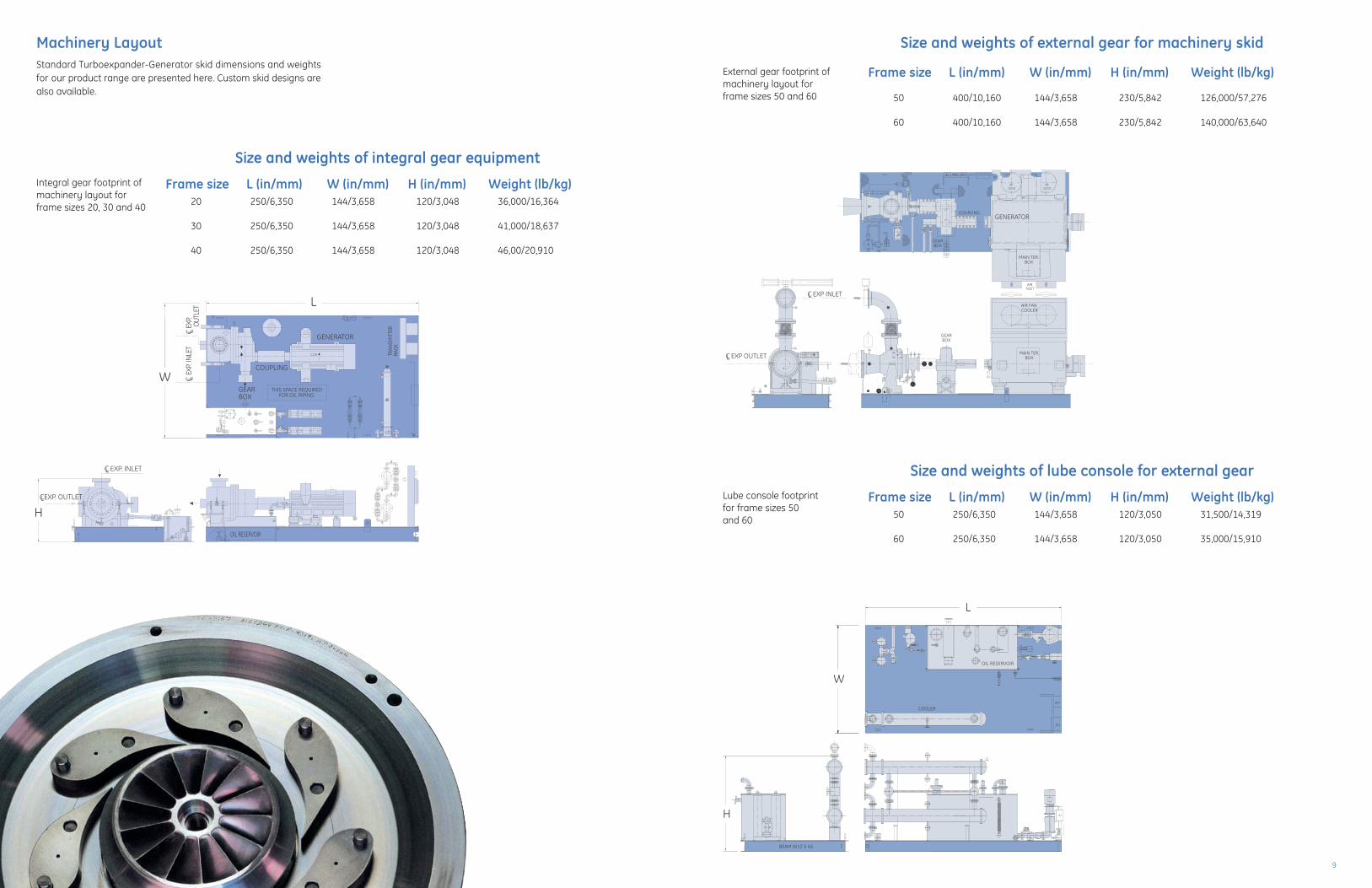
Machinery Layout
Size and weights of integral gear equipment
Frame size L (in/mm) W (in/mm) H (in/mm) Weight (lb/kg)20 250/6,350 144/3,658 120/3,048 36,000/16,364
30 250/6,350 144/3,658 120/3,048 41,000/18,637
40 250/6,350 144/3,658 120/3,048 46,00/20,910
Integral gear footprint ofmachinery layout forframe sizes 20, 30 and 40
Size and weights of external gear for machinery skid
Frame size L (in/mm) W (in/mm) H (in/mm) Weight (lb/kg)
50 400/10,160 144/3,658 230/5,842 126,000/57,276
60 400/10,160 144/3,658 230/5,842 140,000/63,640
Size and weights of lube console for external gear
Frame size L (in/mm) W (in/mm) H (in/mm) Weight (lb/kg)50 250/6,350 144/3,658 120/3,050 31,500/14,319
60 250/6,350 144/3,658 120/3,050 35,000/15,910
External gear footprint ofmachinery layout forframe sizes 50 and 60
Lube console footprintfor frame sizes 50and 60
C.W.
THIS SPACE REQUIREDFOR OIL PIPING
OIL RESERVOIR
STP11
STP31
COUPLING
GENERATOR
RETTIMS
NARTKCARC.C.W.
H
W
L
.PXETELTUO
C LTEL
NI . PXEC L
EXP. INLETCL
EXP. OUTLETCL
GEARBOX
SNEMEISSNEMEIS
EXCITER
JB-E X P -V JB-E X P -T
F J-1
JB-3
41
1
B
AIRNLET
GENERATOR
GEARBOX
GEARBOX
AIR FANCOOLER
MAIN TER.BOX
MAIN TER.BOX
AIROUTLETOUTLET
AIR
COUPLING
EXP OUTLETCL
EXP INLETCL
OIL RESERVOIR
2
JB-2
JB-2
JB-4
BEAM W12 X 45
COOLER
W
L
H
JB-E X P -V JB-E X P -T
F J-1
JB-3
B
Standard Turboexpander-Generator skid dimensions and weightsfor our product range are presented here. Custom skid designs arealso available.

1110
Wherever gas flows, a Rotoflow Turboexpander-Generator can carryout processing tasks while helping to recover energy.
Virtually any high-temperature or high-pressure gas is a potentialresource for energy recovery. Generator-loaded expanders can becustom engineered to recover the maximum amount of usefulenergy available in the process.
In typical investment scenarios, the cost of the installation can berecovered within the first two years. Rotoflow expanders can makea significant contribution to the profitability of your operation byconverting energy for use in the process, or for sale.
Waste heatWaste heat can be converted to useful energy with a Turboexpander-Generator alone or as a component in an Organic Rankine Cycle system.Potential heat sources include: tail gas from industrial furnaces orcombustion engines, waste vapor from industrial furnaces or combustionengines, waste vapor from chemical and petrochemical processes, andsolar heat from flat or parabolic reflectors. Exhaust gases are hot andmay contain solvents or catalysts. An expander can not only recoverenergy and cool down exhaust gases which vent to the atmosphere,it can also separate solvents or catalysts.
Pressure letdownIn pressure letdown applications, such as the merging of two transmissionpipelines at different pressures, or at the city gate of a gas distributionsystem, Rotoflow Turboexpander-Generators can safely reduce thepressure of large volume gas streams while at the same time recoveringenergy in the form of electric power. An expander can therefore be aprofitable replacement for other pressure regulating equipment suchas control valves and regulators.
Reliability and maintenanceRotoflow turboexpanders are designed for long life and easymaintenance. Continuous operation with minimal maintenanceand downtime is essential to an efficient and profitable process.Our dynamically balanced center section can be easily replacedor disassembled for inspection by operating personnel. This allowsour customers to purchase a spare mechanical center sectioninstead of an entire spare machine.
Conversions, Modifications and Uprates In the process industry, it is undeniable that process conditions changeover time. GE Energy can redesign expanders to perform optimally forcurrent, projected, and/or proposed operating conditions. GE Energy’sOil & Gas - Global Services provides a wide range of Conversion,Modification and Uprate (CM&U) products and options includingthe following:
• Performance Upgrade• Programmable Logic Control (PLC) Upgrade• Automatic Thrust Balance of Turboexpander • Conversion of Axial Flow Turbine to Rotoflow Radial Expander• Dry Gas Seal Conversion
GE Energy is rare among suppliers to the oil and gas industry. It isa single-source supplier capable of providing integrated solutions toevery segment of the industry.
When you choose Rotoflow Turboexpanders for your processes,you initiate a continuing partnership that extends well beyond design,delivery and installation. Total life cycle quality management isfundamental to every GE Energy project.
A project team will work with you through every stage of the engineeringand manufacturing process. A Project Manager leads this team andbecomes your advocate and your principal contact during engineering,manufacturing, delivery and commissioning.
The partnership does not end at startup. Through GE Energy GlobalServices your installation can be maintained in peak operating conditionthroughout its life cycle – and its operating life can often be extendedthrough the installation of new technology designed to meet futureprocessing and business challenges.
Global Services for Rotoflow Turboexpander-Generator owners
• Service is available 24 hours a day, every day of the year, fromlocal facilities.
• Experienced service personnel are continually updated on newproducts and techniques.
• Service Centers are always ready to analyze, evaluate andprovide recommendations regarding your plant operation.
• Turboexpander Remote Monitoring and Diagnostics is availableover the internet.
• Contractual Service Agreements allow you to ensure futureperformance at a fixed cost.
Energy Recovery Applications for RotoflowTurboexpander-Generators
Integrated Solutions for Every Segmentof the Industry
A three stage expander mounted on asingle integral gear. This natural gas pressureletdown application handles 68 MMSCFD(76,000 Nm 3/hr) and produces 5-MW ofelecrical power.
Located in Sicily, Italy, an Integrated GasificationCombined Cycle facility uses a RotoflowTurboexpander/Generator to reduce the fuelgas pressure into its gas turbines. At the sametime it produces 10-MW of electricity byexpanding 313 MMSCFD (350,000 Nm 3/hr).
A pressure letdown installation recovers1,000,000 kWh/yr from a southern California,US municipal natural gas pipeline.
Laser holography machine.

TURBOXGEN-NA-01/05
Nuovo Pignone S.p.A.Via Felice Matteucci, 250127 Florence, ItalyT +39 055 423 211F +39 055 423 2800
GE Oil & Gas Operations, LLC3300 Medalist DriveOshkosh, Wisconsin 54902 USAT +1-920-237-6000F +1-920-237-6013
GE Oil & Gas Operations, LLC - Rotoflow540 East Rosecrans AvenueGardena, California 90248 USAT +1-310-329-8447F +1-310-329-8502
Visit us online at:www.geoilandgas.com
©2005 General Electric CompanyAll Rights Reserved