ordering guide of the tray patching & splicing shelf (fist...
TRANSCRIPT
FIST-GPS2 (& FIST-GPST-12) Ordering guide PM Luc Devooght
Page 1 of 25 Issue 2.3 08-2004
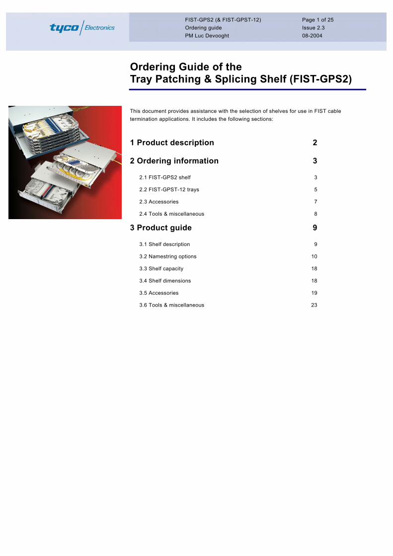
Ordering Guide of the Tray Patching & Splicing Shelf (FIST-GPS2)
This document provides assistance with the selection of shelves for use in FIST cable termination applications. It includes the following sections: 1 Product description 2
2 Ordering information 3
2.1 FIST-GPS2 shelf 3 2.2 FIST-GPST-12 trays 5 2.3 Accessories 7 2.4 Tools & miscellaneous 8
3 Product guide 9
3.1 Shelf description 9 3.2 Namestring options 10 3.3 Shelf capacity 18 3.4 Shelf dimensions 18 3.5 Accessories 19 3.6 Tools & miscellaneous 23
FIST-GPS2 (& FIST-GPST-12) Ordering guide PM Luc Devooght
Page 2 of 25 Issue 2.3 08-2004
1 Product description
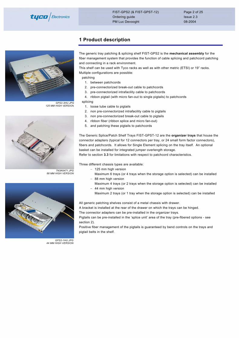
The generic tray patching & splicing shelf FIST-GPS2 is the mechanical assembly for the fiber management system that provides the function of cable splicing and patchcord patching and connecting in a rack environment. This shelf can be used with Tyco racks as well as with other metric (ETSI) or 19” racks. Multiple configurations are possible:
patching 1. between patchcords 2. pre-connectorized break-out cable to patchcords 3. pre-connectorized intrafacility cable to patchcords 4. ribbon pigtail (with micro fan-out to single pigtails) to patchcords
splicing GPS2-3HU.JPG125 MM HIGH VERSION 1. loose tube cable to pigtails
2. non pre-connectorized intrafacility cable to pigtails 3. non pre-connectorized break-out cable to pigtails 4. ribbon fiber (ribbon splice and micro fan-out) 5. and patching these pigtails to patchcords
The Generic Splice/Patch Shelf Trays FIST-GPST-12 are the organizer trays that house the connector adapters (typical for 12 connectors per tray, or 24 small form factor connectors), fibers and patchcords. It allows for Single Element splicing on the tray itself. An optional basket can be installed for integrated jumper overlength storage. Refer to section 3.3 for limitations with respect to patchcord characteristics. Three different chassis types are available:
− 125 mm high version Maximum 6 trays (or 4 trays when the storage option is selected) can be installed
7N3K6471.JPG88 MM HIGH VERSION
− 88 mm high version Maximum 4 trays (or 2 trays when the storage option is selected) can be installed
− 44 mm high version Maximum 2 trays (or 1 tray when the storage option is selected) can be installed
All generic patching shelves consist of a metal chassis with drawer. A bracket is installed at the rear of the drawer on which the trays can be hinged. The connector adapters can be pre-installed in the organizer trays. Pigtails can be pre-installed in the ‘splice unit’ area of the tray (pre-fibered options - see section 2). Positive fiber management of the pigtails is guaranteed by bend controls on the trays and pigtail belts in the shelf.
GPS2-1HU.JPG44 MM HIGH VERSION
FIST-GPS2 (& FIST-GPST-12) Ordering guide PM Luc Devooght
Page 3 of 25 Issue 2.3 08-2004
2 Ordering information
2.1 FIST-GPS2 shelf
Refer to section 3 for full product descriptions.
AA
MANA
PAQA
--
--
--T12A
--U12A
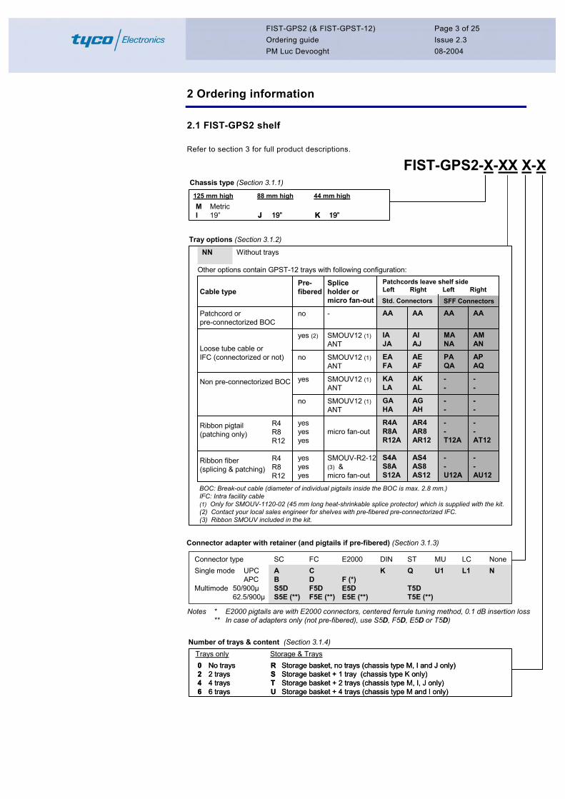
Tray options (Section 3.1.2)
FIST-GPS2-X-XX X-X
NN Without trays
Other options contain GPST-12 trays with following configuration:
Cable type
Patchcord orpre-connectorized BOC
Loose tube cable orIFC (connectorized or not)
Non pre-connectorized BOC
Ribbon pigtail(patching only)
Ribbon fiber(splicing & patching)
Spliceholder ormicro fan-out
-
SMOUV12 (1)ANT
SMOUV12 (1)ANT
SMOUV12 (1)ANT
SMOUV12 (1)ANT
micro fan-out
SMOUV-R2-12 (3) µ fan-out
Std. Connectors
AA
IAJA
EAFA
KALA
GAHA
R4AR8AR12A
S4AS8AS12A
AA
AIAJ
AEAF
AKAL
AGAH
AR4AR8AR12
AS4AS8AS12
BOC: Break-out cable (diameter of individual pigtails inside the BOC is max. 2.8 mm.)IFC: Intra facility cable(1) Only for SMOUV-1120-02 (45 mm long heat-shrinkable splice protector) which is supplied with the kit.(2) Contact your local sales engineer for shelves with pre-fibered pre-connectorized IFC.(3) Ribbon SMOUV included in the kit.
Chassis type (Section 3.1.1)
Number of trays & content (Section 3.1.4)
Pre-fibered
no
yes (2)
no
yes
no
yesyesyes
yesyesyes
R4R8R12
R4R8R12
MI
Metric19” J 19”J 19” K 19”K 19”
125 mm high 88 mm high 44 mm high
0246
No trays2 trays4 trays6 trays
0246
No trays2 trays4 trays6 trays
RSTU
Storage basket, no trays (chassis type M, I and J only)Storage basket + 1 tray (chassis type K only)Storage basket + 2 trays (chassis type M, I, J only)Storage basket + 4 trays (chassis type M and I only)
RSTU
Storage basket, no trays (chassis type M, I and J only)Storage basket + 1 tray (chassis type K only)Storage basket + 2 trays (chassis type M, I, J only)Storage basket + 4 trays (chassis type M and I only)
Trays only Storage & Trays
AA
AMAN
APAQ
--
--
--AT12
--AU12
Patchcords leave shelf sideLeft Right Left Right
Connector adapter with retainer (and pigtails if pre-fibered) (Section 3.1.3)
SFF Connectors
Notes * E2000 pigtails are with E2000 connectors, centered ferrule tuning method, 0.1 dB insertion loss ** In case of adapters only (not pre-fibered), use S5D, F5D, E5D or T5D)
Connector type SC FC E2000 DIN ST MU LC NoneSingle mode UPC A C K Q U1 L1 N
APC B D F (*)Multimode 50/900µ S5D F5D E5D T5D
62.5/900µ S5E (**) F5E (**) E5E (**) T5E (**)
FIST-GPS2 (& FIST-GPST-12) Ordering guide PM Luc Devooght
Page 4 of 25 Issue 2.3 08-2004
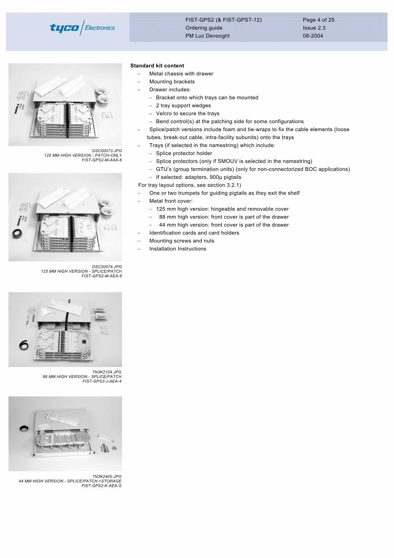
Standard kit content − Metal chassis with drawer − Mounting brackets − Drawer includes:
− Bracket onto which trays can be mounted − 2 tray support wedges − Velcro to secure the trays − Bend control(s) at the patching side for some configurations
− Splice/patch versions include foam and tie-wraps to fix the cable elements (loose tubes, break-out cable, intra-facility subunits) onto the trays
− Trays (if selected in the namestring) which include: DSC00073.JPG
125 MM HIGH VERSION - PATCH-ONLYFIST-GPS2-M-AAA-6
− Splice protector holder − Splice protectors (only if SMOUV is selected in the namestring) − GTU’s (group termination units) (only for non-connectorized BOC applications) − If selected: adapters, 900µ pigtails
For tray layout options, see section 3.2.1) − One or two trumpets for guiding pigtails as they exit the shelf − Metal front cover:
− 125 mm high version: hingeable and removable cover − 88 mm high version: front cover is part of the drawer − 44 mm high version: front cover is part of the drawer
− Identification cards and card holders − Mounting screws and nuts − Installation Instructions
DSC00074.JPG125 MM HIGH VERSION - SPLICE/PATCH
FIST-GPS2-M-AEA-6
7N3K2104.JPG88 MM HIGH VERSION - SPLICE/PATCH
FIST-GPS2-J-AEA-4
7N3K2400.JPG44 MM HIGH VERSION - SPLICE/PATCH +STORAGE
FIST-GPS2-K-AEA-S
FIST-GPS2 (& FIST-GPST-12) Ordering guide PM Luc Devooght
Page 5 of 25 Issue 2.3 08-2004
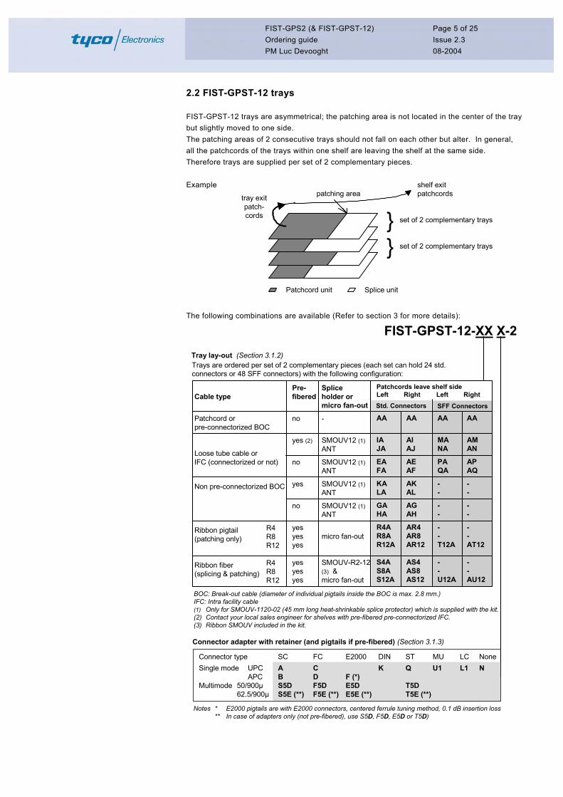
2.2 FIST-GPST-12 trays
FIST-GPST-12 trays are asymmetrical; the patching area is not located in the center of the tray but slightly moved to one side. The patching areas of 2 consecutive trays should not fall on each other but alter. In general, all the patchcords of the trays within one shelf are leaving the shelf at the same side. Therefore trays are supplied per set of 2 complementary pieces. Example
Patchcord unit Splice unit
} set of 2 complementary trays
patching area
} set of 2 complementary trays
tray exitpatch-cords
shelf exitpatchcords
The following combinations are available (Refer to section 3 for more details):
FIST-GPST-12-XX X-2Tray lay-out (Section 3.1.2)Trays are ordered per set of 2 complementary pieces (each set can hold 24 std. connectors or 48 SFF connectors) with the following configuration:
BOC: Break-out cable (diameter of individual pigtails inside the BOC is max. 2.8 mm.)IFC: Intra facility cable(1) Only for SMOUV-1120-02 (45 mm long heat-shrinkable splice protector) which is supplied with the kit.(2) Contact your local sales engineer for shelves with pre-fibered pre-connectorized IFC.(3) Ribbon SMOUV included in the kit.
Connector adapter with retainer (and pigtails if pre-fibered) (Section 3.1.3)
Connector type SC FC E2000 DIN ST MU LC NoneSingle mode UPC A C K Q U1 L1 N
APC B D F (*)Multimode 50/900µ S5D F5D E5D T5D
62.5/900µ S5E (**) F5E (**) E5E (**) T5E (**)
AA
MANA
PAQA
--
--
--T12A
--U12A
Cable type
Patchcord orpre-connectorized BOC
Loose tube cable orIFC (connectorized or not)
Non pre-connectorized BOC
Ribbon pigtail(patching only)
Ribbon fiber(splicing & patching)
Spliceholder ormicro fan-out
-
SMOUV12 (1)ANT
SMOUV12 (1)ANT
SMOUV12 (1)ANT
SMOUV12 (1)ANT
micro fan-out
SMOUV-R2-12 (3) µ fan-out
Std. Connectors
AA
IAJA
EAFA
KALA
GAHA
R4AR8AR12A
S4AS8AS12A
AA
AIAJ
AEAF
AKAL
AGAH
AR4AR8AR12
AS4AS8AS12
Pre-fibered
no
yes (2)
no
yes
no
yesyesyes
yesyesyes
R4R8R12
R4R8R12
AA
AMAN
APAQ
--
--
--AT12
--AU12
Patchcords leave shelf sideLeft Right Left Right
SFF Connectors
Notes * E2000 pigtails are with E2000 connectors, centered ferrule tuning method, 0.1 dB insertion loss ** In case of adapters only (not pre-fibered), use S5D, F5D, E5D or T5D)
FIST-GPS2 (& FIST-GPST-12) Ordering guide PM Luc Devooght
Page 6 of 25 Issue 2.3 08-2004
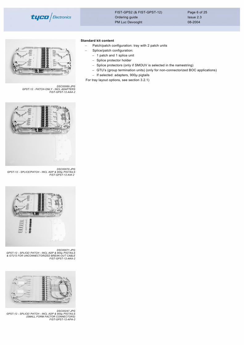
Standard kit content − Patch/patch configuration: tray with 2 patch units − Splice/patch configuration:
− 1 patch and 1 splice unit − Splice protector holder − Splice protectors (only if SMOUV is selected in the namestring) − GTU’s (group termination units) (only for non-connectorized BOC applications) − If selected: adapters, 900µ pigtails
For tray layout options, see section 3.2.1) DSC00069.JPG
GPST-12 - PATCH-ONLY - INCL ADAPTERSFIST-GPST-12-AAA-2
DSC00070.JPGGPST-12 - SPLICE/PATCH - INCL ADP & 900µ PIGTAILS
FIST-GPST-12-AIA-2
DSC00070.JPGGPST-12 - PATCH/SPLICE - INCL ADP & 900µ PIGTAILS
FIST-GPST-12-AEA-2
GPST-12 - SPLICE/ PATCH - INCL ADP & & GTU’S FOR UNCONNECTORIZED BREA
FIST-G
GPST-12 - SPLICE/ PATCH - INCL ADP & (SMALL FORM FACTOR C
FIST-G
DSC00071.JPG900µ PIGTAILSK-OUT CABLEPST-12-AKA-2
DSC00247.JPG900µ PIGTAILSONNECTORS)PST-12-APA-2
FIST-GPS2 (& FIST-GPST-12) Ordering guide PM Luc Devooght
Page 7 of 25 Issue 2.3 08-2004
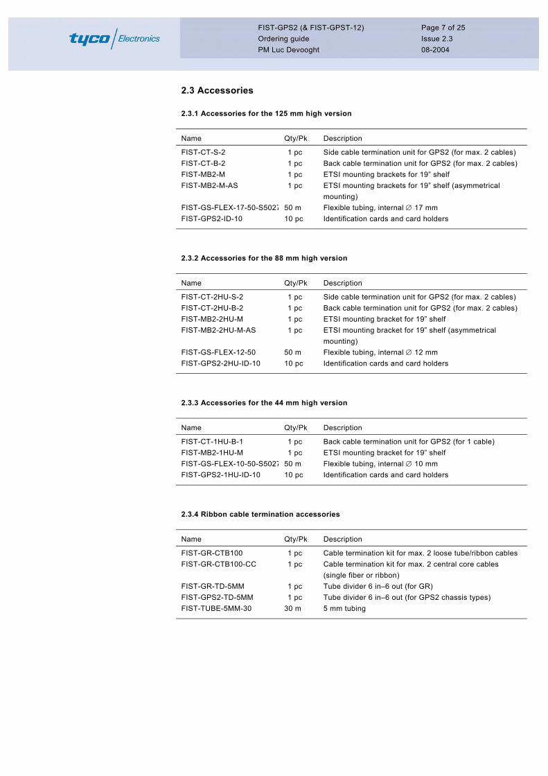
2.3 Accessories
2.3.1 Accessories for the 125 mm high version
Name Qty/Pk Description
FIST-CT-S-2 1 pc Side cable termination unit for GPS2 (for max. 2 cables) FIST-CT-B-2 1 pc Back cable termination unit for GPS2 (for max. 2 cables) FIST-MB2-M 1 pc ETSI mounting brackets for 19” shelf FIST-MB2-M-AS 1 pc ETSI mounting brackets for 19” shelf (asymmetrical
mounting) FIST-GS-FLEX-17-50-S5027 50 m Flexible tubing, internal ∅ 17 mm FIST-GPS2-ID-10 10 pc Identification cards and card holders
2.3.2 Accessories for the 88 mm high version
Name Qty/Pk Description
FIST-CT-2HU-S-2 1 pc Side cable termination unit for GPS2 (for max. 2 cables) FIST-CT-2HU-B-2 1 pc Back cable termination unit for GPS2 (for max. 2 cables) FIST-MB2-2HU-M 1 pc ETSI mounting bracket for 19” shelf FIST-MB2-2HU-M-AS 1 pc ETSI mounting bracket for 19” shelf (asymmetrical
mounting) FIST-GS-FLEX-12-50 50 m Flexible tubing, internal ∅ 12 mm FIST-GPS2-2HU-ID-10 10 pc Identification cards and card holders
2.3.3 Accessories for the 44 mm high version
Name Qty/Pk Description
FIST-CT-1HU-B-1 1 pc Back cable termination unit for GPS2 (for 1 cable) FIST-MB2-1HU-M 1 pc ETSI mounting bracket for 19” shelf FIST-GS-FLEX-10-50-S5027 50 m Flexible tubing, internal ∅ 10 mm FIST-GPS2-1HU-ID-10 10 pc Identification cards and card holders
2.3.4 Ribbon cable termination accessories
Name Qty/Pk Description
FIST-GR-CTB100 1 pc Cable termination kit for max. 2 loose tube/ribbon cables FIST-GR-CTB100-CC 1 pc Cable termination kit for max. 2 central core cables
(single fiber or ribbon) FIST-GR-TD-5MM 1 pc Tube divider 6 in–6 out (for GR) FIST-GPS2-TD-5MM 1 pc Tube divider 6 in–6 out (for GPS2 chassis types) FIST-TUBE-5MM-30 30 m 5 mm tubing

FIST-GPS2 (& FIST-GPST-12) Ordering guide PM Luc Devooght
Page 8 of 25 Issue 2.3 08-2004
2.4 Tools & miscellaneous
Name Qty/Pk Description
FIST-GTU2 18 pc Group termination units FISTV-E7187-6316 25 m Velcro roll FACC-CAGE-NUT-TOOL 1 pc Cage nut installation tool FACC-ALLEN-KEY-5-350 1 pc Allen key, diameter 5 mm, length 350 mm for back
mounting of shelf in rack
FIST-GPS2 (& FIST-GPST-12) Ordering guide PM Luc Devooght
Page 9 of 25 Issue 2.3 08-2004
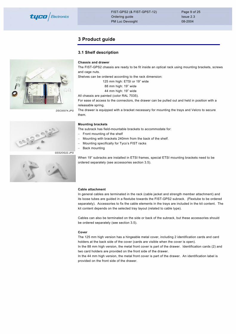
3 Product guide
3.1 Shelf description
DSC00074.JPG
Chassis and drawer The FIST-GPS2 chassis are ready to be fit inside an optical rack using mounting brackets, screws and cage nuts. Shelves can be ordered according to the rack dimension: 125 mm high: ETSI or 19” wide 88 mm high: 19” wide 44 mm high: 19” wide All chassis are painted (color RAL 7035). For ease of access to the connectors, the drawer can be pulled out and held in position with a releasable spring. The drawer is equipped with a bracket necessary for mounting the trays and Velcro to secure them.
GSS2OG22.JPG
Mounting brackets The subrack has field-mountable brackets to accommodate for: − Front mounting of the shelf − Mounting with brackets 240mm from the back of the shelf. − Mounting specifically for Tyco’s FIST racks − Back mounting When 19” subracks are installed in ETSI frames, special ETSI mounting brackets need to be ordered separately (see accessories section 3.5).
Cable attachment In general cables are terminated in the rack (cable jacket and strength member attachment) and its loose tubes are guided in a flextube towards the FIST-GPS2 subrack. (Flextube to be ordered separately). Accessories to fix the cable elements in the trays are included in the kit content. The kit content depends on the selected tray layout (related to cable type). Cables can also be terminated on the side or back of the subrack, but these accessories should be ordered separately (see section 3.5).
Cover The 125 mm high version has a hingeable metal cover, including 2 identification cards and card holders at the back side of the cover (cards are visible when the cover is open). In the 88 mm high version, the metal front cover is part of the drawer. Identification cards (2) and two card holders are provided on the front side of the drawer. In the 44 mm high version, the metal front cover is part of the drawer. An identification label is provided on the front side of the drawer.

FIST-GPS2 (& FIST-GPST-12) Ordering guide PM Luc Devooght
Page 10 of 25 Issue 2.3 08-2004
3.2 Name string options
3.2.1 Tray layout
FIST-GPS2 can be ordered: − without trays, option NN should be selected in that case. − with trays including connector adapters with retainers – and with pigtails if a pre-
fibered tray layout is selected (see following paragraphs). The tray has a modular design: it consists of a base plate, on which 2 units can be clicked. The tray layout parameter will differ depending on the type of units installed and on which side the patchcords will leave the shelf. patchcord unit splice unit patching area
FGPS2002.JPG
Example: Note that patchcords which enter the shelf at the RIGHT side, are routed to the patchcord unit located at the LEFT side of the tray.
Acable attachment plate
Type AI
splice holder
I
GPS2-015.JPG
In case the patchcords would enter the shelf from the left side; the pigtail unit (A) has to be at the right and the splice unit (I) at the left; this setup would require a type IA. The splice unit will get a different parameter depending on the splice holder type and whether the unit has to be pre-fibered or not. The different tray layout options are described in the following paragraphs.
FIST-GPS2 (& FIST-GPST-12) Ordering guide PM Luc Devooght
Page 11 of 25 Issue 2.3 08-2004
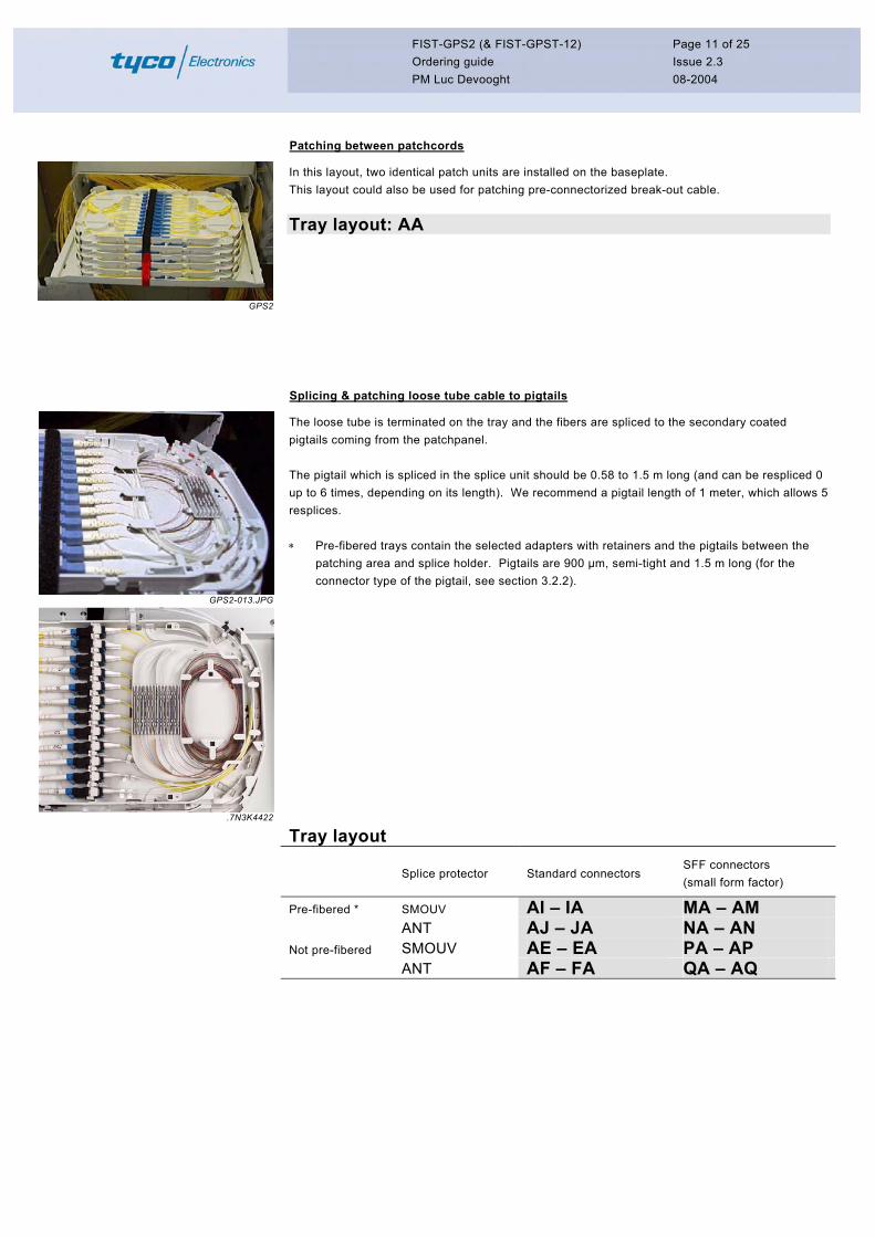
Patching between patchcords
GPS2
In this layout, two identical patch units are installed on the baseplate. This layout could also be used for patching pre-connectorized break-out cable. Tray layout: AA
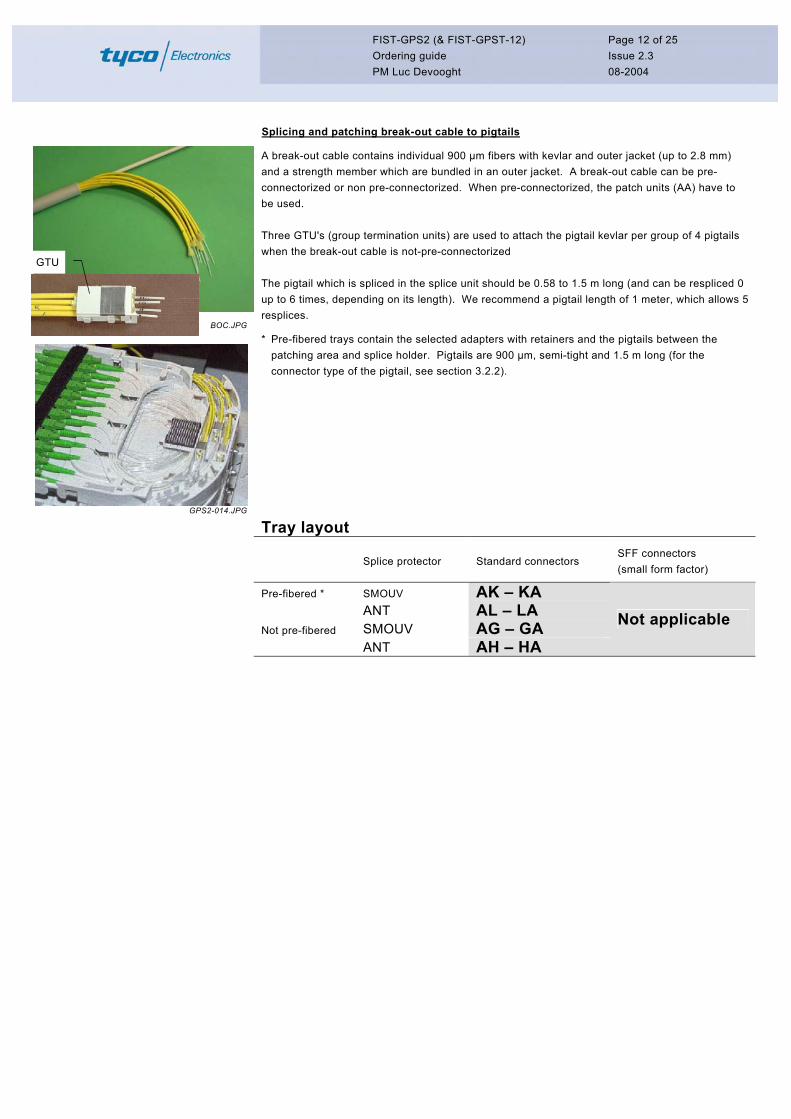
Splicing & patching loose tube cable to pigtails
GPS2-013.JPG
.7N3K4422
The loose tube is terminated on the tray and the fibers are spliced to the secondary coated pigtails coming from the patchpanel. The pigtail which is spliced in the splice unit should be 0.58 to 1.5 m long (and can be respliced 0 up to 6 times, depending on its length). We recommend a pigtail length of 1 meter, which allows 5 resplices. ∗ Pre-fibered trays contain the selected adapters with retainers and the pigtails between the
patching area and splice holder. Pigtails are 900 µm, semi-tight and 1.5 m long (for the connector type of the pigtail, see section 3.2.2).
Tray layout
Splice protector Standard connectors SFF connectors (small form factor)
Pre-fibered * SMOUV AI – IA MA – AM ANT AJ – JA NA – AN Not pre-fibered SMOUV AE – EA PA – AP
ANT AF – FA QA – AQ
FIST-GPS2 (& FIST-GPST-12) Ordering guide PM Luc Devooght
Page 12 of 25 Issue 2.3 08-2004
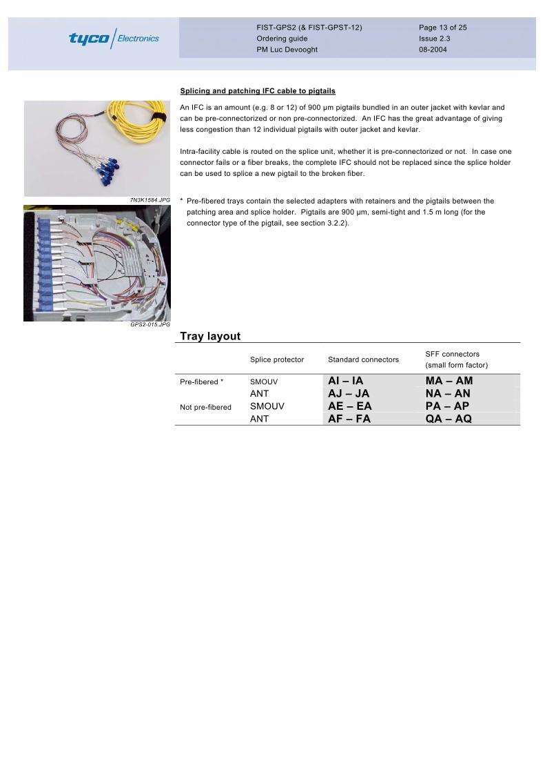
Splicing and patching break-out cable to pigtails
BOC.JPG
GPS2-014.JPG
A break-out cable contains individual 900 µm fibers with kevlar and outer jacket (up to 2.8 mm) and a strength member which are bundled in an outer jacket. A break-out cable can be pre-connectorized or non pre-connectorized. When pre-connectorized, the patch units (AA) have to be used. Three GTU's (group termination units) are used to attach the pigtail kevlar per group of 4 pigtails when the break-out cable is not-pre-connectorized The pigtail which is spliced in the splice unit should be 0.58 to 1.5 m long (and can be respliced 0 up to 6 times, depending on its length). We recommend a pigtail length of 1 meter, which allows 5 resplices.
* Pre-fibered trays contain the selected adapters with retainers and the pigtails between the patching area and splice holder. Pigtails are 900 µm, semi-tight and 1.5 m long (for the connector type of the pigtail, see section 3.2.2).
Tray layout
Splice protector Standard connectors SFF connectors (small form factor)
Pre-fibered * SMOUV AK – KA ANT AL – LA Not pre-fibered SMOUV AG – GA
ANT AH – HA
Not applicable
GTU
FIST-GPS2 (& FIST-GPST-12) Ordering guide PM Luc Devooght
Page 13 of 25 Issue 2.3 08-2004
Splicing and patching IFC cable to pigtails
7N3K1584.JPG
GPS2-015.JPG
An IFC is an amount (e.g. 8 or 12) of 900 µm pigtails bundled in an outer jacket with kevlar and can be pre-connectorized or non pre-connectorized. An IFC has the great advantage of giving less congestion than 12 individual pigtails with outer jacket and kevlar. Intra-facility cable is routed on the splice unit, whether it is pre-connectorized or not. In case one connector fails or a fiber breaks, the complete IFC should not be replaced since the splice holder can be used to splice a new pigtail to the broken fiber.
* Pre-fibered trays contain the selected adapters with retainers and the pigtails between the patching area and splice holder. Pigtails are 900 µm, semi-tight and 1.5 m long (for the connector type of the pigtail, see section 3.2.2).
Tray layout
Splice protector Standard connectors SFF connectors (small form factor)
Pre-fibered * SMOUV AI – IA MA – AM
ANT AJ – JA NA – AN
Not pre-fibered SMOUV AE – EA PA – AP ANT AF – FA QA – AQ
FIST-GPS2 (& FIST-GPST-12) Ordering guide PM Luc Devooght
Page 14 of 25 Issue 2.3 08-2004
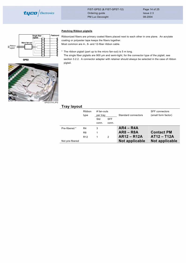
Patching Ribbon pigtails
Micro fan-out
Single fiber pigtails
Ribbon pigtail
GPS2
Patchcord
Micro fan-out
Single fiber pigtails
Ribbon pigtail
GPS2
Patchcord
GPS2-016.JPG
Ribbonized fibers are primary coated fibers placed next to each other in one plane. An acrylate coating or polyester tape keeps the fibers together. Most common are 4-, 8- and 12-fiber ribbon cable. * The ribbon pigtail (part up to the micro fan-out) is 5 m long.
The single fiber pigtails are 900 µm and semi-tight, for the connector type of the pigtail, see section 3.2.2. A connector adapter with retainer should always be selected in the case of ribbon pigtail.
Tray layout
Ribbon type
# fan-outs per tray Standard connectors
SFF connectors (small form factor)
Std conn.
SFF conn.
Pre-fibered * R4 3 AR4 – R4A
R8 1 AR8 – R8A Contact PM R12 1 2 AR12 – R12A AT12 – T12A Not pre-fibered Not applicable Not applicable
FIST-GPS2 (& FIST-GPST-12) Ordering guide PM Luc Devooght
Page 15 of 25 Issue 2.3 08-2004
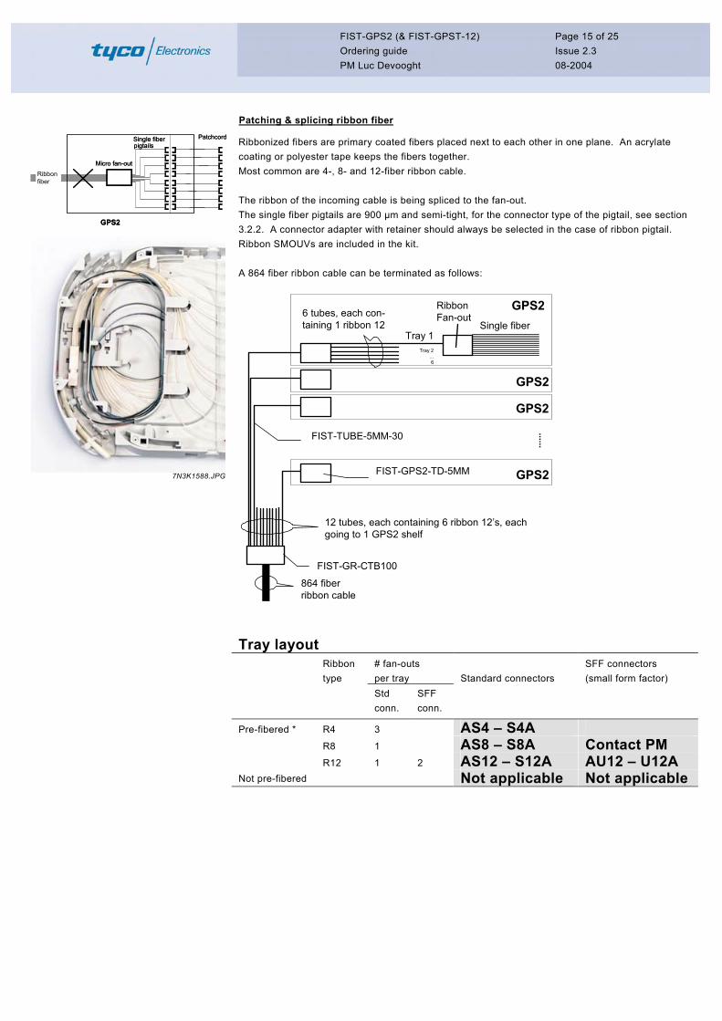
Patching & splicing ribbon fiber
Micro fan-out
Single fiber pigtails
GPS2
Patchcord
Ribbon fiber
Micro fan-out
Single fiber pigtails
GPS2
Patchcord
Ribbon fiber
7N3K1588.JPG
Ribbonized fibers are primary coated fibers placed next to each other in one plane. An acrylate coating or polyester tape keeps the fibers together. Most common are 4-, 8- and 12-fiber ribbon cable. The ribbon of the incoming cable is being spliced to the fan-out. The single fiber pigtails are 900 µm and semi-tight, for the connector type of the pigtail, see section 3.2.2. A connector adapter with retainer should always be selected in the case of ribbon pigtail. Ribbon SMOUVs are included in the kit. A 864 fiber ribbon cable can be terminated as follows:
Single fiber
12 tubes, each containing 6 ribbon 12’s, each going to 1 GPS2 shelf
864 fiber ribbon cable
6 tubes, each con-taining 1 ribbon 12
Tray 1Tray 2
...6
GPS2FIST-GPS2-TD-5MM
FIST-TUBE-5MM-30
FIST-GR-CTB100
GPS2
GPS2
GPS2
RibbonFan-out
Tray layout
Ribbon type
# fan-outs per tray Standard connectors
SFF connectors (small form factor)
Std conn.
SFF conn.
Pre-fibered * R4 3 AS4 – S4A
R8 1 AS8 – S8A Contact PM R12 1 2 AS12 – S12A AU12 – U12A Not pre-fibered Not applicable Not applicable
FIST-GPS2 (& FIST-GPST-12) Ordering guide PM Luc Devooght
Page 16 of 25 Issue 2.3 08-2004
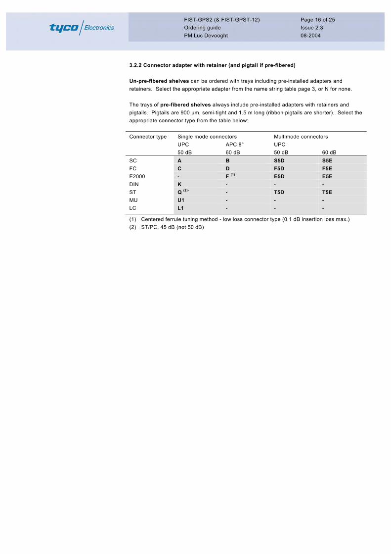
3.2.2 Connector adapter with retainer (and pigtail if pre-fibered)
Un-pre-fibered shelves can be ordered with trays including pre-installed adapters and retainers. Select the appropriate adapter from the name string table page 3, or N for none. The trays of pre-fibered shelves always include pre-installed adapters with retainers and pigtails. Pigtails are 900 µm, semi-tight and 1.5 m long (ribbon pigtails are shorter). Select the appropriate connector type from the table below:
Single mode connectors Multimode connectors UPC APC 8° UPC
Connector type
50 dB 60 dB 50 dB 60 dB SC A B S5D S5E FC C D F5D F5E E2000 - F (1) E5D E5E DIN K - - - ST Q (2)- - T5D T5E MU U1 - - - LC L1 - - -
(1) Centered ferrule tuning method - low loss connector type (0.1 dB insertion loss max.) (2) ST/PC, 45 dB (not 50 dB)
FIST-GPS2 (& FIST-GPST-12) Ordering guide PM Luc Devooght
Page 17 of 25 Issue 2.3 08-2004
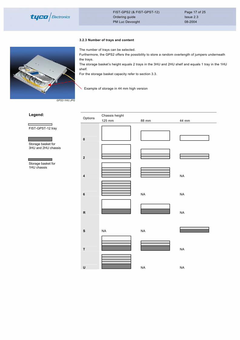
3.2.3 Number of trays and content
GPS2-1HU.JPG
The number of trays can be selected. Furthermore, the GPS2 offers the possibility to store a random overlength of jumpers underneath the trays. The storage basket’s height equals 2 trays in the 3HU and 2HU shelf and equals 1 tray in the 1HU shelf. For the storage basket capacity refer to section 3.3. Example of storage in 44 mm high version
Chassis height Options
125 mm 88 mm 44 mm
0
2
4 NA
6 NA NA
R NA
S NA NA
T NA
U NA NA
Legend:
FIST-GPST-12 tray
Storage basket for3HU and 2HU chassis
Storage basket for 1HU chassis

FIST-GPS2 (& FIST-GPST-12) Ordering guide PM Luc Devooght
Page 18 of 25 Issue 2.3 08-2004
3.3 Shelf capacity
Chassis type Capacity M, I J K
# trays per shelf − without storage basket − with storage basket
6 4
4 2
2 1
# connectors per shelf − without storage basket − with storage basket
Std. 72 48
SFF 144 96
Std. 48 24
SFF 96 48
Std. 24 12
SFF 48 24
Storage basket capacity (for ∅ 2.4 mm patchcords)
48 x 3 m 24 x 4.5 m 12 x 3.5 m
Compatible tray (set of 2 trays) FIST-GPST-12-XXX-2 # connectors per tray 12 (std. connectors) / 24 (SFF connectors) Splicing capacity per tray 12 or 24 splices when splice unit is used Jumper length inside shelf 0.9 m Limitations with respect to patchcord characteristics The shelf for standard connectors is designed for patchcords with ∅ 2.4 mm. The shelf for SFF connectors is designed for patchcords with ∅ 1.7 mm and the length of the connector inclusive boot shall be max. 40 mm for the pigtails located at the splicing side of the tray. Contact the product manager for applications not covered by this document. 3.4 Shelf dimensions
Chassis type Dimensions in mm M I J K
Width (with/without mounting brackets) 531 / 494 481 / 444 481 / 444 481 - 444
Height HU - Height units
125 5 metric HU
125 3 19” HU
88 2 19” HU
44 1 19” HU
Depth 280 280 280 280
Note: A HU is a “height unit”. Refer to rack documentation for more details.
FIST-GPS2 (& FIST-GPST-12) Ordering guide PM Luc Devooght
Page 19 of 25 Issue 2.3 08-2004
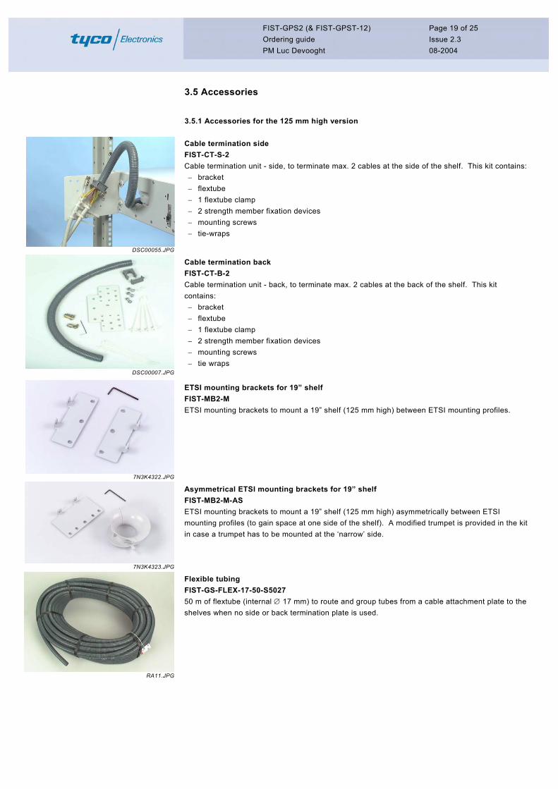
3.5 Accessories
3.5.1 Accessories for the 125 mm high version
DSC00055.JPG
Cable termination side FIST-CT-S-2 Cable termination unit - side, to terminate max. 2 cables at the side of the shelf. This kit contains: − bracket − flextube − 1 flextube clamp − 2 strength member fixation devices − mounting screws − tie-wraps
DSC00007.JPG
Cable termination back FIST-CT-B-2 Cable termination unit - back, to terminate max. 2 cables at the back of the shelf. This kit contains: − bracket − flextube − 1 flextube clamp − 2 strength member fixation devices − mounting screws − tie wraps
7N3K4322.JPG
ETSI mounting brackets for 19” shelf FIST-MB2-M ETSI mounting brackets to mount a 19” shelf (125 mm high) between ETSI mounting profiles.
7N3K4323.JPG
Asymmetrical ETSI mounting brackets for 19” shelf FIST-MB2-M-AS ETSI mounting brackets to mount a 19” shelf (125 mm high) asymmetrically between ETSI mounting profiles (to gain space at one side of the shelf). A modified trumpet is provided in the kit in case a trumpet has to be mounted at the ‘narrow’ side.
RA11.JPG
Flexible tubing FIST-GS-FLEX-17-50-S5027 50 m of flextube (internal ∅ 17 mm) to route and group tubes from a cable attachment plate to the shelves when no side or back termination plate is used.

FIST-GPS2 (& FIST-GPST-12) Ordering guide PM Luc Devooght
Page 20 of 25 Issue 2.3 08-2004
7N3K5401.JPG
Identification cards and card holders FIST-GPS2-ID-10 10 identification cards and card holders. For detailed layout, see Addendum 1.
3.5.2 Accessories for the 88 mm high version
DSC00002.JPG
Cable termination side FIST-CT-2HU-S-2 Cable termination unit - side, to terminate max. 2 cables at the side of the shelf. This kit contains: − bracket − flextube − 1 flextube clamp − 2 strength member fixation devices − mounting screws − tie-wraps
DSC00005.JPG
Cable termination back FIST-CT-2HU-B-2 Cable termination unit - back, to terminate max. 2 cables at the back of the shelf. This kit contains: − bracket − flextube − 1 flextube clamp − 2 strength member fixation devices − mounting screws − tie wraps
DCP03891.JPG
ETSI mounting brackets for 19” (88 mm) shelf FIST-MB2-2HU-M ETSI mounting bracket to mount a 19” shelf between ETSI mounting profiles.
Asymmetrical ETSI mounting brackets for 19” (88 mm) shelf FIST-MB2-2HU-M-AS ETSI mounting brackets to mount a 19” shelf (88 mm high) asymmetrically between ETSI mounting profiles (to gain space at one side of the shelf).
FIST-GPS2 (& FIST-GPST-12) Ordering guide PM Luc Devooght
Page 21 of 25 Issue 2.3 08-2004
RA11.JPG
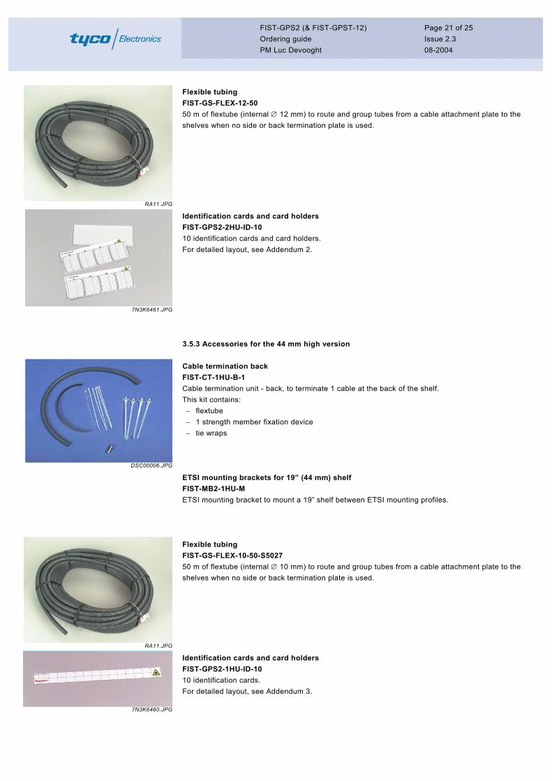
Flexible tubing FIST-GS-FLEX-12-50 50 m of flextube (internal ∅ 12 mm) to route and group tubes from a cable attachment plate to the shelves when no side or back termination plate is used.
7N3K6461.JPG
Identification cards and card holders FIST-GPS2-2HU-ID-10 10 identification cards and card holders. For detailed layout, see Addendum 2.
3.5.3 Accessories for the 44 mm high version
DSC00006.JPG
Cable termination back FIST-CT-1HU-B-1 Cable termination unit - back, to terminate 1 cable at the back of the shelf. This kit contains: − flextube − 1 strength member fixation device − tie wraps
ETSI mounting brackets for 19” (44 mm) shelf FIST-MB2-1HU-M ETSI mounting bracket to mount a 19” shelf between ETSI mounting profiles.
RA11.JPG
Flexible tubing FIST-GS-FLEX-10-50-S5027 50 m of flextube (internal ∅ 10 mm) to route and group tubes from a cable attachment plate to the shelves when no side or back termination plate is used.
7N3K6460.JPG
Identification cards and card holders FIST-GPS2-1HU-ID-10 10 identification cards. For detailed layout, see Addendum 3.
FIST-GPS2 (& FIST-GPST-12) Ordering guide PM Luc Devooght
Page 22 of 25 Issue 2.3 08-2004
3.5.4 Ribbon cable termination accessories
GCO2OG14.JPG
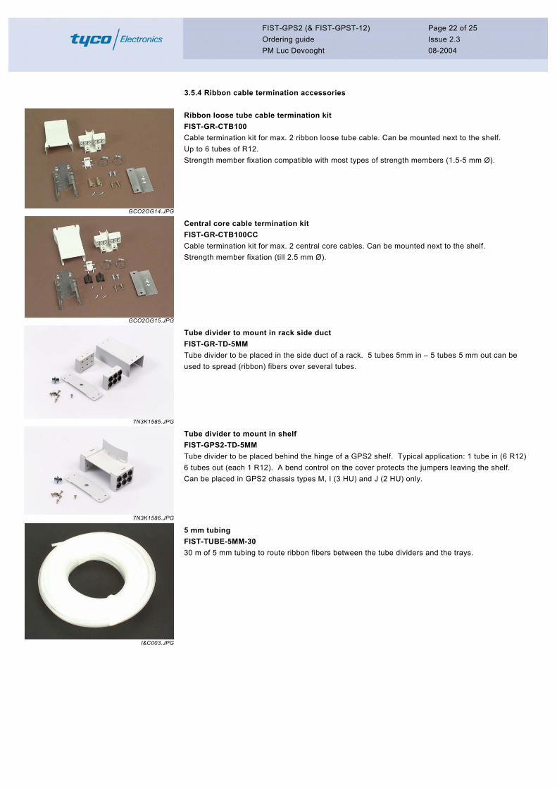
Ribbon loose tube cable termination kit FIST-GR-CTB100 Cable termination kit for max. 2 ribbon loose tube cable. Can be mounted next to the shelf. Up to 6 tubes of R12. Strength member fixation compatible with most types of strength members (1.5-5 mm Ø).
GCO2OG15.JPG
Central core cable termination kit FIST-GR-CTB100CC Cable termination kit for max. 2 central core cables. Can be mounted next to the shelf. Strength member fixation (till 2.5 mm Ø).
7N3K1585.JPG
Tube divider to mount in rack side duct FIST-GR-TD-5MM Tube divider to be placed in the side duct of a rack. 5 tubes 5mm in – 5 tubes 5 mm out can be used to spread (ribbon) fibers over several tubes.
7N3K1586.JPG
Tube divider to mount in shelf FIST-GPS2-TD-5MM Tube divider to be placed behind the hinge of a GPS2 shelf. Typical application: 1 tube in (6 R12) 6 tubes out (each 1 R12). A bend control on the cover protects the jumpers leaving the shelf. Can be placed in GPS2 chassis types M, I (3 HU) and J (2 HU) only.
I&C003.JPG
5 mm tubing FIST-TUBE-5MM-30 30 m of 5 mm tubing to route ribbon fibers between the tube dividers and the trays.
FIST-GPS2 (& FIST-GPST-12) Ordering guide PM Luc Devooght
Page 23 of 25 Issue 2.3 08-2004
3.6 Tools & miscellaneous
DSC00099.JPG
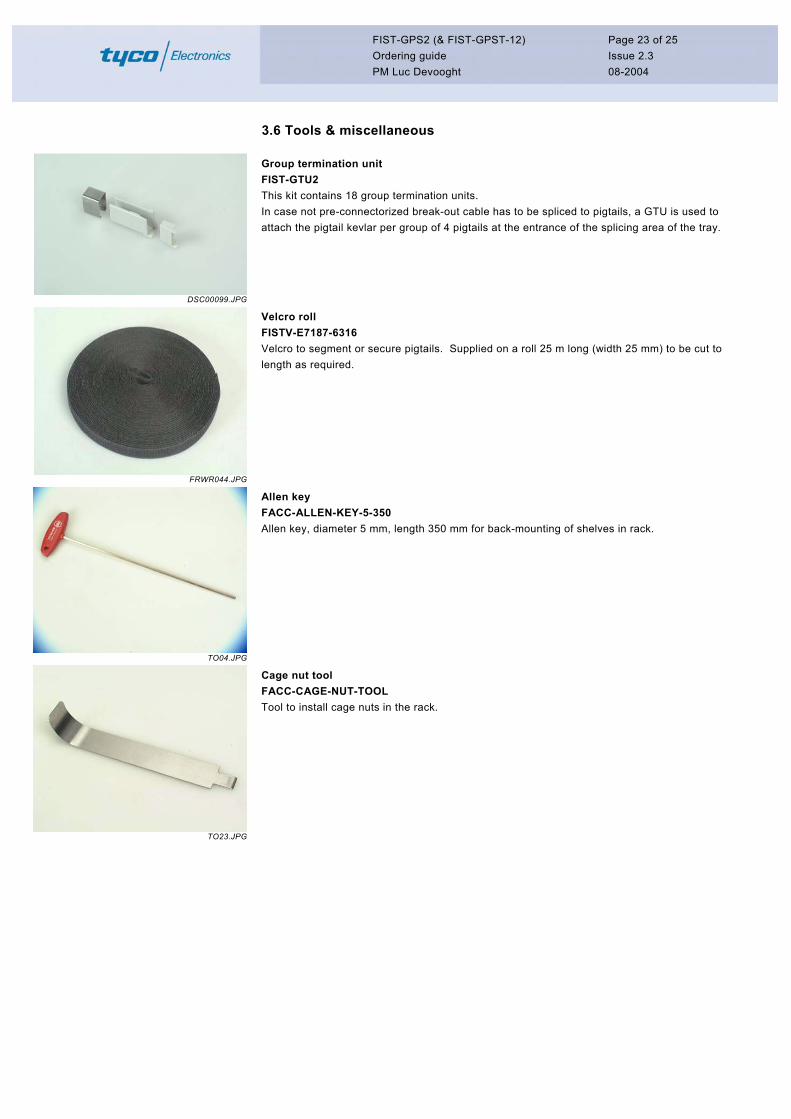
Group termination unit FIST-GTU2 This kit contains 18 group termination units. In case not pre-connectorized break-out cable has to be spliced to pigtails, a GTU is used to attach the pigtail kevlar per group of 4 pigtails at the entrance of the splicing area of the tray.
FRWR044.JPG
Velcro roll FISTV-E7187-6316 Velcro to segment or secure pigtails. Supplied on a roll 25 m long (width 25 mm) to be cut to length as required.
TO04.JPG
Allen key FACC-ALLEN-KEY-5-350 Allen key, diameter 5 mm, length 350 mm for back-mounting of shelves in rack.
TO23.JPG
Cage nut tool FACC-CAGE-NUT-TOOL Tool to install cage nuts in the rack.
FIST-GPS2 (& FIST-GPST-12) Ordering guide PM Luc Devooght
Page 24 of 25 Issue 2.3 08-2004
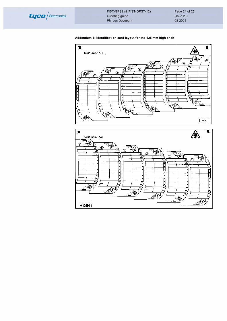
Addendum 1: identification card layout for the 125 mm high shelf
FIST-GPS2 (& FIST-GPST-12) Ordering guide PM Luc Devooght
Page 25 of 25 Issue 2.3 08-2004
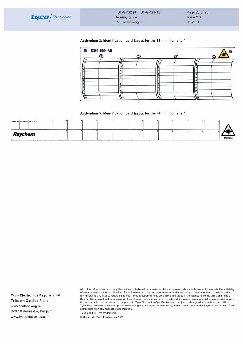
Addendum 2: identification card layout for the 88 mm high shelf
Addendum 3: identification card layout for the 44 mm high shelf
Tyco Electronics Raychem NV Telecom Outside Plant Diestsesteenweg 692 B-3010 Kessel-Lo, Belgium www.tycoelectronics.com
All of this information, including illustrations, is believed to be reliable. Users, however, should independently evaluate the suitability of each product for their application. Tyco Electronics makes no warranties as to the accuracy or completeness of the information and disclaims any liability regarding its use. Tyco Electronics’ only obligations are those in the Standard Terms and Conditions of Sale for this product and in no case will Tyco Electronics be liable for any incidental, indirect or consequential damages arising from the sale, resale, use or misuse of the product. Tyco Electronics Specifications are subject to change without notice. In addition, Tyco Electronics reserves the right to make changes in materials or processing, without notification to the Buyer, which do not affect compliance with any applicable specification. Tyco and FIST are trademarks.
Copyright Tyco Electronics 1999