tc577 ip 4 07 05 - ye internationalyeint.lt/yeint//home/public/techinfo/tosp/sviesolaidine...
TRANSCRIPT

FIST-GSS2I N S T A L L A T I O N I N S T R U C T I O N
Fist Generic Splicing Shelf MK2
1 Introduction
2 General
2.1 Kit content2.2 Tools2.3 Optional extra’s
3 Installation of the shelf
3.1 Mounting the shelf in the rack3.2 Preparation of the shelf3.3 Preparation of the trays
4 Cable termination
4.1 Loose tube (single fiber)a) Cable entrance at the side of
the shelfb) Cable entrance at the back of
the shelfc) Universal side termination
4.2 Central core (single fiber or ribbon)a) Termination in the rack
4.3 Modular cablea) Cable termination at the side of
the shelf4.4 Termination of IFC cable
a) Cable termination in the shelf
5 Termination of the pigtails
6 Splicing + storage
6.1 General6.2 Ribbon
7 Closing the shelf
8 Important steps
Contents
1 Introduction
Product function
• The Generic Splicing Shelf, FIST-GSS2, is a multi-purpose mechanical shelf assembly for the FIST fibermanagement system in a rack environment.
• The product is typically used :- to store splices of external cable to external/indoor cable- to store splices of external cable to pigtails.- to store splices of pigtails to pigtails
• It can be installed in Raychem’s FIST Racks and other 19” or metric (ETSI) rack sizes.• Accessories are available for termination of most common cable types.• Modular wraparound groove plates can be clicked in the UMS (Universal Mounting System) profile. They
provide the foundation for mounting combinations of SOSA2 (Splicing Only Sub-Assembly) and/or SASA2(Splitter Array Sub-Assembly) modules. Typically, Single Circuit or ribbon fiber management is used.
• Kevlar Termination Units (KTU’s) can be mounted in the shelf to provide the necessary strain relief whenterminating common pigtail types.
• The shelf is delivered with a metal hingable cover.

2
Kit content: example: FIST-GSS2-MA
• 1 shelf, incorporating• Metal chassis with drawer• Hingable and removable front cover• Pre-mounted tubes• Pre-mounted FAS block + cover• 1 pigtail horn• 1 tray lid + fiber guiding pin• 1 cable entrance kit for 2 loose tube cables• Cage nuts + bolts• Mounting brackets + screws• FOPT CT transportation tubing• Installation instruction
Items needed for an installation of modular cable
FIST-GSS2-CT-S-2
• Side termination plate and screws• Two strength member connectors and screws• Stand off bracket• Four releasable tie wraps
2 General
2.1 Kit content
2.2 Tools
• FACC-ALLEN-KEY-5-350 to mount unit in the rack• FACC-CAGE-NUT-TOOL for easy installation of cage nuts
in the rack• FACC-TUBE-CUTTER-01 cutter for transportation tubes• FACC-TUBE-STRIPPER-02 loose tube stripper• FACC-FIBRE-FEEDER• Marker pen
2.3 Optional extras
• FISTV-E7187-6316 Velcro rolls• FIST-GR-CTB100 Cable term. kit for loose tube
ribbon cable• FIST-GR-CTB100CC Cable term. kit for central core
cable (single fiber or ribbon)• FIST-GSS2-CT-BR-2 Cable back termination kit
(strength member in the rack)• FIST-GSS2-CT-BS-2 Cable back termination kit
(strength member on the shelf)• FIST-PTK2 Pigtail Termination Kit including:
- Bracket to hold 4 KTUs- 4 x KTU (max. Ø 3.1 mm
single fiber pigtails (2x) or ribbon pigtails)
• FIST-ITK2 IF cable termination bracket for 12 cables
• FIST-MB2-M Adaption brackets 19” -- ETSI• FIST-GS-FLEX-17-50 50 m flexible tubing (ID 17mm)• FIST-UST-XX Side cable termination unit• FIST-MB2-M-AS Asymmetric adaption bracket
9”-ETSI
3.1 Install the mounting brackets on the correct position. GR mounting is shown.
3 Installation of the shelf
3.1 Mounting the shelf in the rack
3.1.2 Determine the position of the unit (see rack installationinstruction). Fix the cage nuts into the rack mounting uprights.

3
3.1.3 If a non-Raychem rack is being used it is possible that thecage nuts may not fit. In this case use locally supplied ones and installin accordance with local practices. Observe and respect minimumdimensions of the unit.
3.1.4 Mount the unit using the FACC-ALLEN-KEY.
3.1.5 If necessary mount the adaption brackets 19”-ETSI(FIST-MB2-M or FIST-MB2-M-AS).

4
3.2 Preparation of the shelf 3.3 Preparation of the trays
3,2,3 If needed remove the cover by bending it carefully.
3.2.1 Install the trumpet by positioning it centrally in the openingat the side of the shelf, align the small knobs with the slots in the side,Strongly push and turn until the locking pin clicks into positioning hole.
3.3.1 Pull the drawer to the fully open position. Remove the Velcroand the fasblock cover by lifting the back side of the cover.
3.3.3 Remove sharp edges.
3.3.2 Remove the plastic piece at one side of the groove platesusing pliers.
3.2.2 If needed the horn can easily be turned to an open position.
a) Cable to pigtail

5
3.3.5 Depending on the configuration: fill up the unit with grooveplates, don’t leave any gaps.
3.3.4 Click the groove plates on the aluminum profiles starting fromthe FAS block; don’t leave any gaps. First position the pins of thegroove plate at the back and pull the groove plate to the front until itlocks.
3.3.6 If necessary, the groove plates can be removed using 2 flatscrewdrivers.
3.3.7 Mount the KTU brackets. Start at the left. Push until they lock.

6
3.3.10 In case of SE trays (sigle element trays), start at the secondposition and leave 1 space between all the other trays.
3.3.8 In case of a pure cable-cable configuration: no KTU-bracketsare placed, the groove plates are not modified, tubes enter at bothsides of the FAS block.
3.3.9 Click the trays on the groove plates starting from the fasblock.Preferably mount the trays as you fibre up.In case of SC trays (single circuit trays); don’t leave any gaps.
4.1.3 For back and GR mounting: mount the flex tube holder in thethird hole.
4.1.2 Mounting position: position the toothed lock washer (1)between the tube holder and the side plate.
3.3.11 If necessary, trays can be removed using the fiber guiding pin.
4 Cable termination
4.1 Loose tube (single fiber)
a) Cable entrance at the side of the shelf
4.1.1 Take the tubes out of the unit. To avoid kinking of the tubesmake sure the drawer is closed. To assure correct bendradius: do notreposition the fixed tie wrap.
b) Cable to cable
c) Mounting the trays
1

7
4.1.4 In case 2 flex tubes will be used: remove the releasable tie-wrap and mount the plastic stand-off in the first hole from the front.
4.1.7 Identify the loose tubes and feed them through the flex tube.Wrap PVC tape around the tubes at the end of the cable to makefeeding easier.
4.1.5 Prepare a piece of flex tube going from the cable terminationplate in the rack to the flex tube holder on the unit.
4.1.6 Cable and strength member termination will usually be done inthe rack. Terminate the cable in the rack according to Tyco rackinstallation instruction and local practice. Leave 3.5 m of loose tubemeasured from the end of the flex tube.
4.1.11 Mark the transportation tube at 30 mm from the end of theflex tube. Mark the loose tube at 20 mm from the end of the flex tube.
4.1.9 Mount the fixed tie wrap at the position as shown.
4.1.8 Bring the flex tube into the flex tube holder.
4.1.10 In case of front mounting of the shelf: mount the fixed tie wrapas shown.
70 mm
85
mm

8
4.1.13 Select a loose tube and slide a 75mm long FOPT-CT over thetransportation tube and loose tube..
4.1.14 Route all tubes underneath the plastic stand-off and close theflex tube holder with the cover.
4.1.15 Pull the fibers at the other end of the tubes.
4.1.16 If no more loose tubes have to be terminated, cut the unusedtubes. Secure the tubes with a tie-wrap.
4.1.17 A second cable can be added using the second flex tubeholder.
4.1.12 Strip the loose tubes from the mark and cut the overlength ofthe transportation tubes.

9
b) Cable entrance at the back of the shelf
4.1.18 Always remove the 2 tie wraps at the bottom of the tray.
4.1.19 In case of strength member termination in the rack (use FIST-GSS2-CT-BR-2): mount the flex tube holder and the plastic stand-off. Mount the tubes to the black stand-off with a tie wrap. Protect thetubes with the spiral tubing and make sure the bend is smooth.Terminate as shown (for details see similar side termination).
4.1.20 In case of a second cable, replace the releasable tie wrap by asecond stand-off.
4.1.21 In case of strength member termination on the shelf (use FIST-GSS2-CT-BS-2): mount the cable plate, the strength memberconnectors, the black stand-off and the tie-wraps as shown in 4.1.21and 4.1.23.Use the plastic spacers between plate and shelf. The distance betweenthe plate and the right side of the shelf X is 8 cm for a 19” shelf and10,5 cm for an ETSI shelf.
4.1.22 Remove 3.5 m cable jacket. Leave 55 mm of the strengthmember.
X
4.1.23 Mount the transportation tubes as shown. Protect the tubeswith a 200 mm spiral tubing and make sure the bend is smooth.
4.1.24 Install the cables. Strip the loose tube at 50 mm from the cablejacket end. Cut the transportation tube at 60 mm from the cable jacketend. Slide a 75 mm long FOPT-CT over the transition. If the loose tubediameter < 2,3 mm the use of the FOPT-CT is not needed. (In this casedon’t cut the transportation tubes too short).

10
4.1.25 Mount the side termination plate on the shelf.
4.1.29 Mark the transportation tubes 10 mm from the plastic stand-off. Mark the loose tubes 30 mm from the plastic stand-off.
c) Universal side termination
4.1.26 Strip the cable over 3,5 m. Cut the strength member at 40 mm from the outer jacket. Apply foam tape at the tie wrappositions. Install the prepared cable on the side termination plate.Install the plastic stand-off as shown.
4.1.30 After stripping the loose tubes and cutting of the overlength ofthe transportation tubes, slide the FOPT-CT over the transportationtubes.
4.1.27 Mount the fixed tie wrap at the position as shown.
4.1.28 In case of front mounting, mount the fixed tie wrap as shown.
70 mm
85
mm

11
4.1.31 The FOPT-CT should overlap loose tube and transportationtube.
FIST-GR-CTB100CC (central core)1 Breakout device2 Breakout device cover + screws3 Cable bracket + screws4 Mounting bracket + washers + screws5 2 cable clamps6 Unraveling tool7 2 strength member stops + screws
1
23
4
65
7
4. 2 Central core (single fiber or ribbon) and loose tube ribbon
a) Termination in the rack
FIST-GR-CTB100 (loose tube ribbon)1 Breakout device2 Breakout device cover + screws3 Cable bracket + screws4 Mounting bracket + washers + screws5 2 cable clamps6 Unraveling tool7 2 strength member terminations + screws
1
2
3 4
56
7
4.1.32 Transportation tubes can be fixed on the plastic stand-off withtie wraps.
4.1.33 Maximum capacity of the universal side termination plate is 4cables, 2 on top of each other with the spacer inbetween the strengthmember connectors.
4.1.34 An extra plate can be used with a limitation of 2 cables on topof each other; positions as shown.

12
4.2.2 Place the breakout device on the cable bracket.
4.2.3 Prepare the cable. Make sure you have 3,5 m fiber inside theshelf. Respect dimensions shown on the drawings. Clean the fibersvery well to make easy feeding possible.
4.2.4 Loose tube ribbon cable.
4.2.7 Secure with the cable clamp. Don’t squeeze the cable.
4.2.5 Central core cable
4.2.6 In case of central core cable: loosen the screw of the strengthmember stop. Rotate the stop and position the strength members.
20
20
4.2.8 In case of loose tube cablePosition the strength member at the bottom. Bundle the loose tubeswith tape. Secure the strength member with the screws.
4.2.1 Choose a position in the side duct or on the cable terminationplate as close as possible to the GSS. Mount the mounting bracket onthat position with the two screws. Mount the cable bracket with twoscrews on the mounting bracket.

13
4.2.9 In case of ribbon cableRemove twists in the ribbons.a) If ribbons are according ITU norms: use the unraveling device. The
numbers indicate the number of ribbons you want to bundle (3-4-5 or 6). 3 sizes of ribbon can be handled: ribbon 12, 8 and 4.(3 groove sizes).
b) In other cases use local practice.
4.2.10 Slide the tool over the ribbons. Bundle at the end using Teflontape (bundle in groups as you want to feed them through the tubes).Remove the unraveling device.
4.2.11 Cut the tubes to length using the tube cutter. Make sure theshelf is in an opened position.
4.2.13 Feed the fiber groups in the tubes. Start at the back to haveeasy access. Avoid crossings of the fibers.
4.2.12 Insert the tubes in the connectors. Use 6 positions at the leftwhen cable is mounted at the left side of the bracket.
4.2.14 Slide the cover over the break-out and secure with the screws.

14
4.3.1 Assemble the releasable tie wraps and the strength memberconnectors onto the side termination plate as shown in the picture.
Modular cable Modular cable Loose tube cable Pigtails6 mm 2.5 mm 12 fibers
Pigtails GSS2-XA FIST-GSS2-XA-MC FIST-GSS2-XA FIST-GSS2-XA(standard) (special MC) (standard) (standard)96 fibers 72 fibers* 96 fibers 48 fibers (SASA)**
Loose tube cable FIST-GSS2-XC FIST-GSS2-XC-MC FIST-GSS2-XC FIST-GSS2-XA12 fibers (standard) (special MC) (standard) (standard)
96 fibers 72 fibers 96 fibers 96 fibers
Modular cable FIST-GSS2-XC-MC FIST-GSS2-XC-MC FIST-GSS2-XC-MC FIST-GSS2-XA-MC2.5 mm (2 or 4 fibers) (special MC) (special MC) (special MC) (special MC)
72 fibers* max. 48 fibers** 72 fibers* 72 fibers*
Modular cable FIST-GSS2-XC FIST-GSS2-XC-MC FIST-GSS2-XC FIST-GSS2-XA6 mm (standard) (special MC) (standard) (standard)
96 fibers 72 fibers* 96 fibers 96 fibers
X = M = metricI = 19’
2nd digit = A = cable to pigtailC = cable to cable
* 144 splices in case of 4 fiber microcable and 4 splices per SC tray** 96 splices in case of 4 fiber microcable and 4 splices per SC tray
4,3 Modular cable
a) Cable termination of the side of the shelf
When splicing modular cable in a FIST-GSS2, the shelf type has to beused depends on the configuration (incoming cable type, outgoingcable type). For some configurations, a standard FIST-GSS2 can beused, for other, a modular cable version of the splicing shelf (FIST-GSS2-XY-MC) has to be used.The table underneath shows which shelf type has to be used for eachpossible configuration with modular cable and its splice capacity forthat application.

15
4.3.2 Install the side termination bracket on the shelf, beforemounting the shelf in the rack.
4.3.5 Remove the outer cable jacket over a distance of 3500 mmstarting from the side term plate and cut the strength member at 65 mm from the cable jacket.
4.3.6 It is recommended to install the blocking between the 10 mmmicroduct and microcable at the bottom of the rack.
4.3.7 Remove the micro tube up to 200 mm from the cable jacketand clean the fibers.
4.3.3 Install the two stand off brackets in the first and the third holefrom the front of the shelf.
4.3.8 Wrap some layers of teflon tape around the ends of thestrength members to keep them together.Note: to avoid crossings of the loose buffer tubes and the strengthmembers, 2 strength members can be cut if necessary.
4.3.4 Secure the transportation tubes on the stand off brackets intwo bundles as shown in the picture.
4.3.9 Insert the strength member into the strength memberconnector and tighten the screw.

16
4.3.10 Feed the fiber bundle through the transportation tubes to thedesignated splicing trays.
4.3.11 Secure the cable with the tie wraps on the side terminationplate.
4.4.1 Kit content FIST-ITK2• 1 pc IFC-bracket• 2 pcs bolts & nuts• 24 pcs Tie-wraps• 1 pc Velcro wrap• 1 pc adhesive foam tape
4.4.3 Remove the cable jacket over approximately 1.7 m.
4.4.2 Mount the bracket onto the shelf using the bolts & nuts.
4.4 Termination of IFC cable
a) Cable termination in teh shelf
4.4.4 Apply one layer of foam tape around the IF-cable, at the endof the jacket. This tape prevents easy pull-out of the cable.
4.4.5 Feed the IF through the horn.

17
4.4.9 Make sure the transition of secondary to primary coating isin the splice protector. If this is not possible: strip the secondary coating(semi-tight) in the middle of the groove plate.
4.4.8 In case of single circuit tray (SC): 2 fibers can be terminated.The following positions should be used on the metal bracket:1, 2, 4, 5, 7, 8, 10, 11 (max. capacity: 8 x12 = 96 fibers).In case of single circuit (SC trays) with 4 semi-tight fibers par tray, useall the bracket positions and remove the secondary coating in themiddle of the groove plate. Do not use (= leave empty) trays number4, 8, 12, 16, ... (max. capacity = 144 fibers).
4.4.7 In case of Single Element cassettes (SE): 6 fibers can beterminated per tray (max. capacity: 12 x 12 = 144 fibers).
4.4.6 Fasten the cable onto the bracket with the tie-wraps. Don’tsqueeze the cable !!! For ease of installation start at the left.
5.1 Route the pigtails without leaving any slack through thetrumpet, through the KTU bracket to the correct tray. Mark in themiddle or at the end of the tray to have some slack for sliding the tray.
5 Termination of the pigtails
5.2 Remove the jacket beyond the marking point. Cut away thekevlar leaving 50-100 mm from the edge of the jacket. Cut the pigtailsleaving ± 1.7 m length after the marking point.

18
5.3 Mount the 2 pieces of the KTU as shown.
In case of 2 pigtails
5.4 Guide the prepared pigtail in the KTU. Make sure the kevlaryarns do not entangle the fibers.
5.5 Close the KTU.
5.6 Slide the inner part to the left as much as possible by pullingthe jacket and kevlar at the same time.Cut the excess kevlar leaving 5-10 mm.
5.8 Guide the prepared pigtails in the KTU. Make sure the kevlaryarns do not entangle the fibers. Keep the kevlar from each pigtailseparated.
5.9 Slide the inner part to the left as much as possible by pullingthe jacket and kevlar at the same time.Cut the excess kevlar leaving 5-10 mm.
5.7 In case of 2 pigtails/KTU; identify 1 of the fibers with amarking pen.

19
5.10 In case of less kevlar (typically this means pigtail diameter < 2,3 mm): wrap the kevlar to ensure a good strain relief.
5.11 Installation of first and second pigtail at the same side of theKTU.
In case of 4 pigtails
Diameter of the pigtails maximum 1.8 mm
5.12 Installation of third and fourth pigtail at the opposite side ofthe KTU.
5.13 Close the KTU.
5.14 Pull the jacket and Kevlar at the same time to slide the innerpart of the KTU into the outer part.

20
5.15 Cut the excess of the Kevlar, leaving 5-10 mm.
5.11 Slide the KTU in the correct slot. Respect correct orientation ofthe KTU. The front lip should be positioned left in top view.The position of the KTU’s is indicated on the drawing (application cableto pigtail is indicated).
21
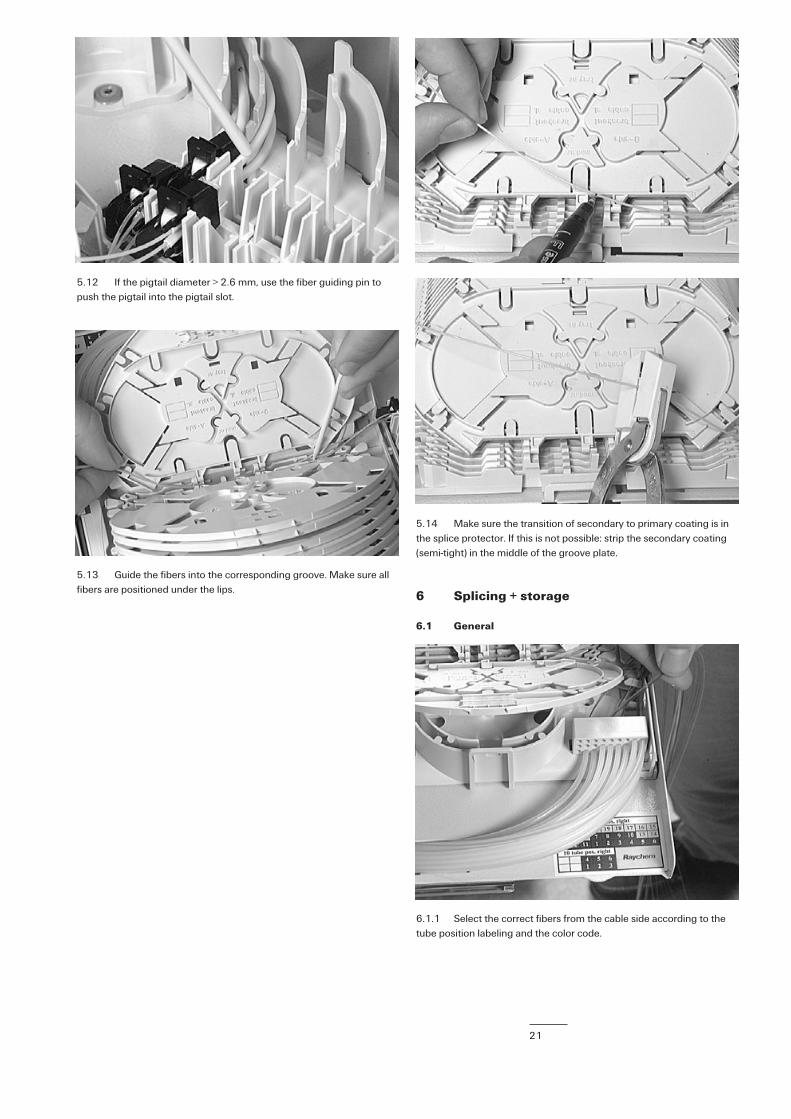
5.12 If the pigtail diameter > 2.6 mm, use the fiber guiding pin topush the pigtail into the pigtail slot.
5.13 Guide the fibers into the corresponding groove. Make sure allfibers are positioned under the lips.
6.1.1 Select the correct fibers from the cable side according to thetube position labeling and the color code.
5.14 Make sure the transition of secondary to primary coating is inthe splice protector. If this is not possible: strip the secondary coating(semi-tight) in the middle of the groove plate.
6 Splicing + storage
6.1 General

22
6.1.3 Store the fibers into the tray. Follow the exact routing asshown. Try to minimize the number of coils.
6.1.2 Guide the fibers in the groove plate. Make sure all fibers arepositioned under the lips. Splice the fibers and protect the splice.Position the splice in the spliceholder. 6.1.4 If both fibers are coming from the same side, follow the routing
as shown.
6.1.5 Use a permanent marker to write splicing information on thetray.
6.2 Ribbon
6.2.1 In case of ribbon pigtail: limit the number of torsions in theorganiser system to avoid optical losses.
Fiber and tube number fromfibers entering in side 1
Fiber and tube N° fromfibers entering in side 2
Tray 1 is closesd tofiber routing block
Side 2 of tray
Cable port N° fromfibers entering tray
in side 2
Cable port N° fromfibers entering tray
in side 1
Side 1 of tray

23
7.2 Put the cap over the fasblock. Click a traylid onto the last tray.Lock the trays with the Velcro.
7.3 Close the drawer by activating the spring on the right side ofthe unit.
7.4 Close the cover.
8 Important steps
• Clean the fibers very well to make feeding easier.• Always respect 30mm bendradius and prevent kinking when
repositioning tie-wraps for the transportation tubes.• Respect overlap dimensions for transition loose tube-
transportation tube.• Strip the loose tubes at 3,5 m.• Provide sufficient pigtail slack for easy sliding of trays.• For each tray select correct groove and KTU position.• Use correct orientation and position of the KTU in the KTU bracket.• Prevent twisting of the ribbon fiber.• Coil the fibers at a maximum diameter, minimize the number of
coils.• Make sure all fibers are positioned under the containment lips.
7.1 After installation, bundle the pigtails with a piece of Velcro. Incase pigtails protrude above the KTU brackets the black tie wrap canbe used.
7 Closing the unit

TC 577/IP/4 07/05
Tyco is a trademark. Kevlar and Teflon are trademarks of E.I. du Pont de Nemours. Velcro is a trademark ofVelcro Industries B.V.
The information given herein, including drawings, illustrations and schematics which are intended for illustration purposes only, isbelieved to be reliable. However, Tyco Electronics makes no warranties as to its accuracy or completeness and disclaims any liabilityin connection with its use. Tyco Electronics’ obligations shall only be as set forth in Tyco Electronics’ Standard Terms and Conditionsof Sale for this product and in no case will Tyco Electronics be liable for any incidental, indirect or consequential damages arising outof the sale, resale, use or misuse of the product. Users of Tyco Electronics products should make their own evaluation to determinethe suitability of each such product for the specific application.
Tyco Electronics Raychem NVTelecom Outside PlantDiestsesteenweg 692B-3010 Kessel-Lo, BelgiumTel.: 32-16-351 011Fax: 32-16-351 697www.tycoelectronics.comwww.telecomosp.com