fist gr2 ordering guidefist-gr2 ordering guide 2.2.4 other accessories issue 1.2 (05-2002) page 6 of...
TRANSCRIPT

Issue 1.2 (05-2002) Page 1 of 17 Product Manager: L.Devooght
FIST Ordering Guide
FIST
Fiber Infrastructure System Technology
Generic Racks (FIST-GR2)
This document provides assistance with the selection of racks for use in FIST applications. It includes the following sections:
Please consult your local sales engineer for applications not included in this document.
1. PRODUCT DESCRIPTION 2. ORDERING INFORMATION
2.1 Generic Rack 2.2 Accessories 2.3 Tools
3. PRODUCT GUIDE 3.1 Rack Description 3.2 Rack Dimensions and Capacity 3.3 Accessories Description 3.4 Tools Description

FIST-GR2 Ordering Guide
Generic Racks (FIST-GR2)
1. PRODUCT DESCRIPTION 1. PRODUCT DESCRIPTION The FIST Generic Rack, FIST-GR2, is an all-purpose metal rack designed to accommodate FIST shelves. The FIST Generic Rack, FIST-GR2, is an all-purpose metal rack designed to accommodate FIST shelves. FIST-GR2 complies with metric ETSI specifications. FIST-GR2 complies with metric ETSI specifications. FIST-GR2 is built around 2 modular units: base frame and side duct, which can be combined to create different lay-outs. Two side duct widths are available (150 mm and 300 mm) to accommodate different patchcord and cable densities.
FIST-GR2 is built around 2 modular units: base frame and side duct, which can be combined to create different lay-outs. Two side duct widths are available (150 mm and 300 mm) to accommodate different patchcord and cable densities.
Base frame
Side duct Side duct
Side door Side door
CEMT (old design)
Base duct
GR2558DS.JPG
Fully loaded FIST-GR2-20-SP
Issue 1.2 (05-2002) Page 2 of 17 Product Manager: L.Devooght

FIST-GR2 Ordering Guide
2. ORDERING INFORMATION
2.1 GENERIC RACK Refer to Section 3 for full product descriptions.
Height
Width (section 3.1.1)
Type
Doors and Panels (section 3.1.2)
SB
Stand alone rack or wall mounting rackBack-to-back rack (without back panel)*
1.8 m2.2 m2.6 m (not to be combined with 150 mm side ducts)
67A8B90C2
NPD
L
123
No panels, no doorsWith panels and side duct doors, no central doorWith panels and metal door(s) for base frame and side duct(s)With panels and metal door(s) +lock (standard key number 00)Side mounting equivalent of P (without side panels)*Side mounting equivalent of D (without side panels)*Side mounting equivalent of L (without side panels)*
FIST-GR2-X X-X X
123
600 mm750 mm (600 + 150)750 mm (150 + 600)900 mm (600 + 300)900 mm (300 + 600)900 mm (150 + 600 + 150)1050 mm (150 + 600 +300)1050 mm (300 + 600 + 150)1200 mm (300 + 600 + 300)
* including rack connection kit for side-to-side mounting
* including rack connection kit for back-to-back mounting Standard Rack Kit Content • Base frame with ETSI mounting profiles and Raychem/Tyco logo • Base duct • Wall connection kit (except for ‘back-to-back’ rack configuration) • Earthing facility (connection of the metal parts to each other and a connection point to
the building earthing) • Adjustable feet • Identification strips on the mounting profiles • Installation instructions • Packed in a reinforced box (flat for rack widths up to 900 mm, about 600 mm thick for
rack widths above 900 mm) • Cable shield grounding facility • Depending on the configuration ‘height and width’, the items listed below are included.
Check the drawings in section 3.1.1 for layout and quantities. • Side ducts (including doors) • Pre-mounted drums on drum plates and drum plate enlargers • Cable attachment plate with C-profile provided with cable clamps and strength
member fixations (CAP 150 for 5 cables ∅ 12-16 mm, CAP 300 for 11 cables ∅ 12-16 mm).
• Drum plate enlargers on remaining positions of the drum plate(s)
Issue 1.2 (05-2002) Page 3 of 17 Product Manager: L.Devooght

FIST-GR2 Ordering Guide
2.2 ACCESSORIES
Issue 1.2 (05-2002) Page 4 of 17 Product Manager: L.Devooght
Accessories are ordered in addition to the basic rack to suit specific applications. Refer to section 3.3 for a complete product description and pictures.
2.2.1 Cable Installation Name Qty/Pk Description
FIST-GR2-CAP-150 1 pc Extra cable attachment plate with C-profile for 150 mm side duct
FIST-GR2-CAP-300 1 pc Extra cable attachment plate with C-profile for 300 mm side duct
Cable attachment accessories Kits including 1 cable clamp (single, double or triple) and 1 (resp. 2 or 3) strength member fixations. See section 2.2.2
FIST-GR2-CAP-150-EXT 1 pc Kit including 4 CAP plates of 150 mm wide and protective cover to mount outside rack (no CSM)
FIST-GR2-CAP-300-EXT 1 pc Kit including 5 CAP plates of 300 mm wide and protective cover to mount outside rack (no CSM)
FIST-GR2-CAP-150-INT 1 pc Extra CAP plate (150 mm wide) to attach IFC or breakout cable. Kit includes spacers and screws to mount it onto another CAP (no C-profile, no CSM)
FIST-GR2-CAP-300-INT 1 pc Extra CAP plate (300 mm wide) without C-profile to attach IFC or breakout cable. Kit includes spacers and screws to mount it onto another CAP (no C-profile, no CSM)
FIST-GR2-UCT-06 6 pc FIST-GR2-UCT-08 8 pc FIST-GR2-UCT-12 12 pc
Extra cable strength member fixations and mini Allen key
FIST-GR2-CEMT-I 1 pc 19” cable element management tray FIST-GR2-CEMT-M 1 pc ETSI cable element management tray FIST-GS-FLEX-17-50-S5027 50 m Flexible tubing (ID 17 mm) FISTV-FTC 10 pcs Clip-on flexible tubing clamps FISTV-TW-NN-188 100 pcs Tie wrap, standard, not re-openable, 188 mm long.Note: - Standard racks are equipped for loose-tube cable constructions.
- Cable termination kits are available for other cable constructions (e.g. central core cable, ribbon fiber cable types) - See FIST-GSS2 and FIST-GMS2 ordering guide.

FIST-GR2 Ordering Guide
2.2.2 Cable attachment accessories Cable attachment accessories are included in the standard rack kit (not for 600 mm wide). Cable attachment accessories for different cable diameter ranges are listed underneath. They include a cable clamp (single, double or triple) and according strength member connector quantities. For CAP capacities, check the FIST-GR2 CAP application guide.
FIST-GR2-CAA-X-XX/XX
Cable clamp type1 Single clamp, 1 strength member fixation2 Double clamp, 2 strength member fixations3 Triple clamp, 3 strength member fixations
Cable diameter range (in mm)12/1616/2222/2828/34
2.2.3 Pigtail Management Name Qty/Pk Description
FIST-GR2-HPM-I 1 pc 19” HPM (Horizontal Pigtail Management) with 6 drums and mounting bracket adapters for symmetrical mounting between ETSI profiles (*)
FIST-GR2-HPM-M 1 pc ETSI HPM (Horizontal Pigtail Management) FIST-GR2-HPS-I 1 pc 19” HPS (Horizontal Pigtail Storage) with 5 drums
and mounting bracket adapters for symmetrical mounting between ETSI profiles (*)
FIST-GR2-HPS-M 1 pc ETSI HPS (Horizontal Pigtail Storage) FIST-GR2-POM-I 1 pc 19” POM (Pigtail Orientation Module) with
mounting bracket adapters for symmetrical mounting between ETSI profiles (*)
FIST-GR2-POM-M 1 pc ETSI POM (Pigtail Orientation Module) FIST-GR2-DPE-150 1 pc Drum plate enlarger for 150 mm side duct FIST-GR2-DPE-300 1 pc Drum plate enlarger for 300 mm side duct FIST-GR2-DRM 10 pcs Bag of drums + mounting screws + nuts FIST-GR2-PCBR-10 10 pcs Bag of pigtail containment brackets
* For asymmetrical mounting brackets, see section 2.2.4.
Issue 1.2 (05-2002) Page 5 of 17 Product Manager: L.Devooght

FIST-GR2 Ordering Guide
2.2.4 Other Accessories
Issue 1.2 (05-2002) Page 6 of 17 Product Manager: L.Devooght
Name Qty/Pk Description FIST-MB-M-AS 1 pc Mounting bracket adapter for asymmetrical
mounting of 19” shelves between ETSI profiles FIST-GR2-STS 1 pc Extra rack connection kit for side-to-side conn. FIST-GR2-BTB 1 pc Extra rack connection kit for back-to-back conn. FIST-GR2-DL1-XX 1 pc 1 door lock for the central door+ 2 keys
XX = 00 for lock with standard key number XX = 01...10 for customer specific key number
FIST-GR2-DL2-XX 2 pc 1 door lock for the central door and 1 for a side door using the same key + 2 keys XX = 00 for lock with standard key number XX = 01...10 for customer specific key number
FIST-GR2-DL3-XX 3 pc 1 door lock for the central door and 2 for the side doors using the same key + 2 keys XX = 00 for lock with standard key number XX = 01...10 for customer specific key number
FISTV-E7187-6316 25 m Velcro roll
2.2.5 Side Duct Kits Ideally, the rack layout is decided on day one. In some cases, extra side ducts are needed. Side ducts (without side panels) for 2.2 m high racks are available separately. They include all necessary parts to be connected to a base frame or other side duct.
Name Qty/Pk Description FIST-GR2-SDK-2-150-LD 1 kit 150 mm wide side duct, 2.2 m high, left hinging
door, fully loaded with drums (no CAP). FIST-GR2-SDK-2-150-RD 1 kit 150 mm wide side duct, 2.2 m high, right hinging
door, fully loaded with drums (no CAP). FIST-GR2-SDK-2-300-LD 1 kit 300 mm wide side duct, 2.2 m high, left hinging
door, fully loaded with drums (no CAP). FIST-GR2-SDK-2-300-RD 1 kit 300 mm wide side duct, 2.2 m high, right hinging
door, fully loaded with drums (no CAP).
2.3 TOOLS Name Qty/Pk Description
FACC-ALLEN-KEY-5-350 1 pc Allen key, diameter 5 mm, length 350 mm for back-mounting of shelves in rack
FACC-CAGE-NUT-TOOL 1 pc Tool to install cage nuts in the rack

FIST-GR2 Ordering Guide
3. PRODUCT GUIDE
3.1 RACK DESCRIPTION A rack consists of a base frame, side duct(s) and a base duct. For rack layouts see section 3.1.1.
Issue 1.2 (05-2002) Page 7 of 17 Product Manager: L.Devooght
Base frame The base frame consists of a metal bottom, back and top panel (for side panels and doors see section 3.1.2). Color RAL 7035, with Raychem/Tyco logo and ETSI mounting profiles for shelf back mounting. In case of 19” shelves extension brackets 19” to ETSI should be used for mounting the shelves on the ETSI mounting profiles. Side duct A side duct consists of a bottom, a back, a top and includes a drum plate (explained underneath) (for side panels and doors see section 3.1.2). It is or shall be attached to the base frame. It is used to manage and house cables, pigtails and patchcords that are routed from the rack entry points to the shelves. Depending on the rack width, side duct(s) are included as follows:
Rack width Rack layout Order ref.
FIST-GR2-XX-XX Total width Left side duct Base frame Right
side duct 6 600 - 600 -
7 750 - 600 150 Not for 2.6 m high
A 750 150 600 - Not for 2.6 m high
8 900 - 600 300
B 900 300 600 -
9 900 150 600 150 Not for 2.6 m high
0 1050 150 600 300 Not for 2.6 m high
C 1050 300 600 150 Not for 2.6 m high
2 1200 300 600 300
Drum plate A drum plate is pre-mounted in a side duct and has pre-installed drums for patchcord routing. (for position of drums in std rack layouts: see section 3.1.1). − The VPM (vertical pigtail management system)
allows for functional overlength storage of patchcords, in order to be able to reach all adapter positions without the need to take the patchcord out of the base duct.
− The VPS (vertical pigtail storage) allows for random overlength storage inside the rack (to absorb jumper overlength between ODF and electronics).
VPM
VPS

FIST-GR2 Ordering Guide
The drum plate has extension brackets at both ends to accommodate either a drum plate enlarger or a cable attachment plate.
DSC00076.JPG
Drum plate enlarger The drum plate enlarger allows the installation of additional drums. It exists in 150 mm and 300 mm width. The standard rack (configurations with side ducts) mostly includes drums on the drum plate enlarger for the purpose of the VPM and VPS. (See section 3.1.1).
DSC00078.JPG DSC00077.JPG
Cable attachment plate Cables enter the rack through the rack top or bottom openings and the cable strength members and cable outer jackets are attached to the cable attachment plate. In the standard kit the cable attachment plate is provided with single cable clamps (for cable ∅ 12-16 mm) and strength member fixations for 5 cables (CAP150) or 11 cables (CAP300). Section 3.1.1 shows which side duct has a CAP for each configuration. Note: no CAP nor clamps or strength member fixations included in the kit of a 600 mm rack. Check the FIST-GR2 CAP capacity guide for more information.
7N3K5907.JPG
Base duct The bottom of the base frame contains a pigtail duct system that is used to carry patchcords from one rack side to the other, or from one rack to another in a back-to-back or side-to-side configuration. Height occupancy: 8 ETSI HU
drum plate extension brackets
Issue 1.2 (05-2002) Page 8 of 17 Product Manager: L.Devooght

FIST-GR2 Ordering Guide
3.1.1 Layout of different rack configurations Drawings of all the possible layouts of the 2.2 m racks are presented underneath. They show where the CAP is initially installed and the number and position of drums and pigtail containment brackets in the standard rack. Most of these layouts are also available for the 1.8 and 2.6 m rack (except 2.6 m high combined with 150 side ducts). The only difference is the number of drums per VPM and VPS:
Rack height VPM VPS 1.8 m 7 drums 6 drums 2.2 m 8 drums 8 drums 2.6 m 9 drums 9 drums
FIST-GR2-26 FIST-GR2-27 FIST-GR2-2A
Issue 1.2 (05-2002) Page 9 of 17 Product Manager: L.Devooght
FIST-GR2-28 FIST-GR2-2B FIST-GR2-29

FIST-GR2 Ordering Guide
FIST-GR2-20 FIST-GR2-2C FIST-GR2-22
3.1.2 Doors and panels The back, left and right side of the rack can be provided with panels. The front of the base frame and the side ducts can be provided with metal doors. Following options are available: N No panels, no doors P With panels and side duct doors, no door on the base frame D With panels and doors on the side ducts and the base frame L With panels and doors with standard lock on the side ducts and the base frame 1 Side mounting equivalent of P (without side panels)* 2 Side mounting equivalent of D (without side panels)* 3 Side mounting equivalent of L (without side panels)*
* Note: For a line-up of multiple FIST-GR2’s, order 1 rack with panels (options P, D or L) and the adjacent racks without panels (options 1, 2 or 3). Remove 1 side panel from the 1st rack and mount it onto the last rack of the line-up.
3.1.3 Other rack characteristics Packing The rack is shipped in a reinforced cardboard crate, mounted horizontally on a wooden pallet. A flat crate is used for racks up to 900 mm wide, whereas a square crate (600 mm high) is used for racks > 900 mm wide.
Wall connection kit This kit is included to attach the rack to the wall (except in ‘back-to-back’ configurations: FIST-GR2-XX-BX).
7N3K0173.JPG
Issue 1.2 (05-2002) Page 10 of 17 Product Manager: L.Devooght

FIST-GR2 Ordering Guide
3.2 RACK DIMENSIONS AND CAPACITY
Issue 1.2 (05-2002) Page 11 of 17 Product Manager: L.Devooght
FIST-GR2-1XXX FIST-GR2-2XXX FIST-GR2-3XXX
Dimensions Height Depth
1.8 m
300 mm
2.2 m
300 mm
2.6 m
300 mm Capacity (in ETSI HU’s) Total available ETSI HU’s (25 mm pitch)(base duct occupies 8 HU’s and is standard included in the rack)
64-8=56
80-8=72
96-8=88
Capacity (in # FIST shelves) 11 14 17
3.2.1 Height occupancy of FIST systems:
FIST System Height occupancy (ETSI HU’s)
Base duct 8
CEMT with cover 5
Base duct with CEMT and cover 13
HPM, HPS 7
POM, Raychem standard shelves 5
Raychem 44 mm high shelves 2
Raychem 88 mm high shelves 4
3.2.2 Pigtail capacity of side ducts, base duct and pigtail management shelves
FIST-HPM, -HPS and –POM are designed to handle 288 pigtails of ∅ 3 mm. For side and base duct capacities, see also the FIST-GR2 capacity guide. 150 mm side duct: VPM only
VPM + 1 drum for cross-connect VPS only
300 mm side duct: VPM can be combined with VPS in 1 side duct base duct: 1008 pigtails of ∅ 2.4 mm

FIST-GR2 Ordering Guide
3.3 ACCESSORIES DESCRIPTION
3.3.1 Cable Installation Cable attachment plate with C-profile FIST-GR2-CAP-150 (150 mm wide) FIST-GR2-CAP-300 (300 mm wide) (picture) This kit contains an extra cable attachment plate with C-profile. Screws to mount it in the side-duct are included. Cable attachment accessories should be ordered separately. 7N3K6730.JPG
Cable attachment plate without C-profile FIST-GR2-CAP-150-INT (150 mm wide) FIST-GR2-CAP-300-INT (300 mm wide) (picture) This kit contains an extra cable attachment plate without C-profile for fixation of flexible cable. Spacers and accessories to mount it onto another CAP are included. Max. 2 (resp. 3) plates can be mounted on top of each other in the bottom (resp. top) of the rack. Cable attachment accessories should be ordered separately.
7N3K6731.JPG
CAP module to mount outside rack FIST-GR2-CAP-150-EXT (150 mm wide) FIST-GR2-CAP-300-EXT (300 mm wide) (picture) This module includes several CAP plates and a protective cover and is designed to be mounted on top of the side duct. The module of 150 mm wide includes 4 CAP plates. The module of 300 mm wide includes 5 CAP plates. Accessories to mount it onto the side duct are included. Cable attachment accessories should be ordered separately.
7N3K6735.JPG
Cable attachment accessories with single cable clamps FIST-GR2-CAA-1-XX/XX XX/XX = cable ∅ range in mm
(12/16, 16/22, 22/28 or 28/34) Kit includes 1 single clamp + 1 CSM (central strength member) fixation + 1 mini Allen key (not shown).
7N3K6726.JPG
Issue 1.2 (05-2002) Page 12 of 17 Product Manager: L.Devooght

FIST-GR2 Ordering Guide
Cable attachment accessories with double cable clamps FIST-GR2-CAA-2-XX/XX XX/XX = cable ∅ range in mm
(12/16, 16/22, 22/28 or 28/34) Kit includes 1 double cable clamp and 2 CSM (central strength member) fixations + 1 mini Allen key (not shown).
7N3K6739.JPG
Cable attachment accessories with triple cable clamps FIST-GR2-CAA-3-XX/XX XX/XX = cable ∅ range in mm
(12/16, 16/22, 22/28 or 28/34) Kit includes 1 triple cable clamp and 3 CSM (central strength member) fixations + 1 mini Allen key (not shown
7N3K6740.JPG
Cable strength member fixation FIST-GR2-UCT-06 FIST-GR2-UCT-08 FIST-GR2-UCT-12 This kit contains 6 (resp. 8,12) extra cable strength member fixations and 1 mini Allen key.
DSC00001.JPG
Cable element management tray FIST-GR2-CEMT-M (ETSI) A cable element management tray can be put in the bottom of the rack above the base duct. It facilitates the routing of cable elements to the shelves. A cover is included. Height occupancy: 5 ETSI HU FIST-GR2-CEMT-I (19”) A 19” CEMT with mounting bracket adapters for installation on ETSI mounting profiles.
7N3K4511.JPG
Flexible tubing FIST-GS-FLEX-17-50-S5027 When guiding loose tubes from the cable termination in the rack to the entrance of the shelf, flexible tubing is used to protect the loose tubes and to control the bend radius. The flexible tubing has a minimum inner diameter of 17 mm and a capacity of up to 8 loose tubes.
RA11.JPG
Issue 1.2 (05-2002) Page 13 of 17 Product Manager: L.Devooght

FIST-GR2 Ordering Guide
Flexible tube clamps FISTV-FTC A set of 10 plastic clamps to be used instead of tie-wraps to secure flexible tubes onto the cable element management tray or other locations. (Screws are included in the kit).
FTC.JPG
Tie wraps FISTV-TW-NN-188 188 mm long tie wraps are used for fixing the cable and flexible tubing to the rack.
I&C025.JPG
3.3.2 Pigtail Management Horizontal pigtail management Height occupancy: 175 mm (7 ETSI HU) Pigtail capacity: see section 3.2.2. FIST-GR2-HPM-M (ETSI) A horizontal pigtail management system can be fitted to store functional overlength of patchcords for patching within the same rack (though VPM has higher capacity). Six half round drums are used to guide patchcords entering from the left or from the right side duct. The system can be fitted in the rack for either left or right patchcord entrance by simply turning it upside down. FIST-GR2-HPM-I (19”) A 19” HPM with mounting bracket adapters for symmetrical installation between ETSI mounting profiles.
7N3K1089.JPG
Horizontal pigtail storage Height occupancy: 175 mm (7 ETSI HU) Pigtail capacity: see section 3.2.2 FIST-GR2-HPS-M (ETSI) A horizontal pigtail storage system can be fitted to store random patchcord overlengths in a controlled way (though VPS has higher capacity). The system contains 6 drums and can be fitted in the rack for either left or right patchcord entrance by simply turning it upside down. FIST-GR2-HPS-I (19”) A 19” HPS with mounting bracket adapters for symmetrical installation on ETSI mounting profiles.
7N3K1091.JPG
Issue 1.2 (05-2002) Page 14 of 17 Product Manager: L.Devooght

FIST-GR2 Ordering Guide
Pigtail orientation module Height occupancy: 5 ETSI HU (125 mm) Pigtail capacity: see section 3.2.2 FIST-GR2-POM-M (ETSI) This module can be inserted in a rack to redirect or branch a pigtail bundle. It can be fitted in the rack for either left or right patchcord entrance by simply turning it upside down. Make sure that the drum at the patchcord entrance is always in the correct position (i.e. guiding the patchcords that are entering the shelf). FIST-GR2-POM-I (19”) A 19” POM with mounting bracket adapters for symmetrical installation on ETSI mounting profiles.
7N3K1093.JPG
Drum plate enlarger FIST-GR2-DPE-150 (for 150 mm side duct) FIST-GR2-DPE-300 (for 300 mm side duct) In case shelves are positioned in the bottom or top of the rack, an extra drum beside those shelves might be required. The drum plate enlarger will be mounted in such case on the bottom or top extension brackets of the drum plate. Drums are included in the kit (but not pre-mounted).
7N3K1095.JPG
7N3K1096.JPG
Bag of drums FIST-GR2-DRM Kit of 10 drums with screws and nuts to fix them to a drum plate.
RACA045.JPG
Bag of pigtail containment brackets FIST-GR2-PCBR-10 Kit of 10 brackets with according fixing hardware.
7N3K7042.JPG
Issue 1.2 (05-2002) Page 15 of 17 Product Manager: L.Devooght

FIST-GR2 Ordering Guide
3.3.3 Other Accessories 19”-ETSI asymmetrical mounting bracket adapter FIST-MB-M-AS Mounting bracket adapter for asymmetrical mounting of 19” HPM, HPS or POM shelves between ETSI profiles. For the other shelves, refer to the shelves ordering guides.
7N3K6937.JPG
Rack connection kit Side-To-Side FIST-GR2-STS This kit provides the accessories to mount a 300 mm deep rack side-to-side with another 300 mm deep rack.
7N3K1097.JPG
Rack connection kit Back-To-Back FIST-GR2-BTB This kit provides the accessories to mount 2 racks back-to-back.
7N3K6751.JPG
Lock(s) and 2 keys for door(s) FIST-GR2-DL1-XX (central door only) FIST-GR2-DL2-XX (central door + 1 side door) FIST-GR2-DL3-XX (central door + 2 side doors) All kits include 2 identical keys. XX = 00 for standard key number XX = 01...10 for customer specific key number
Velcro roll FISTV-E7187-6316 Velcro to segment or secure pigtails. Supplied on a roll 25 m long (width 25 mm) to be cut to length as required.
FRWR044.JPG
Issue 1.2 (05-2002) Page 16 of 17 Product Manager: L.Devooght
FIST-GR2 Ordering Guide
Issue 1.2 (05-2002) Page 17 of 17 Product Manager: L.Devooght
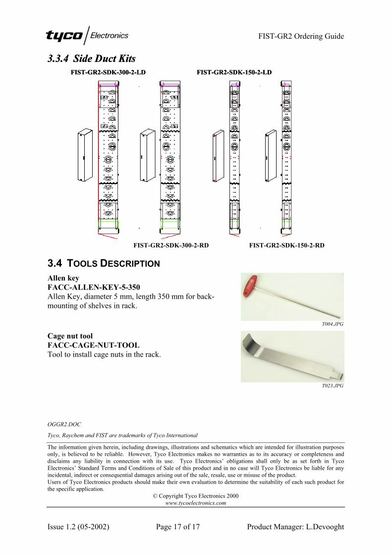
3.3.4 Side Duct Kits 3.3.4 Side Duct Kits FIST-GR2-SDK-300-2-LD FIST-GR2-SDK-150-2-LD FIST-GR2-SDK-300-2-LD FIST-GR2-SDK-150-2-LD
FIST-GR2-SDK-300-2-RD FIST-GR2-SDK-150-2-RD
3.4 TOOLS DESCRIPTION Allen key FACC-ALLEN-KEY-5-350 Allen Key, diameter 5 mm, length 350 mm for back-mounting of shelves in rack.
T004.JPG
Cage nut tool FACC-CAGE-NUT-TOOL Tool to install cage nuts in the rack.
T023.JPG
OGGR2.DOC
Tyco, Raychem and FIST are trademarks of Tyco International
The information given herein, including drawings, illustrations and schematics which are intended for illustration purposes only, is believed to be reliable. However, Tyco Electronics makes no warranties as to its accuracy or completeness and disclaims any liability in connection with its use. Tyco Electronics’ obligations shall only be as set forth in Tyco Electronics’ Standard Terms and Conditions of Sale of this product and in no case will Tyco Electronics be liable for any incidental, indirect or consequential damages arising out of the sale, resale, use or misuse of the product. Users of Tyco Electronics products should make their own evaluation to determine the suitability of each such product for the specific application.
© Copyright Tyco Electronics 2000 www.tycoelectronics.com

Issue 1.0 (04-2002) Page 1 of 9 Product Manager: L.Devooght
Application Guide
CAP FIST-GR2 Cable Attachment Plate
Fiber Infrastructure System Technology
Cable Attachment Plate of FIST Generic Rack 2
Summary
1. CAP changes overview
2. Application 1: CAP with C-profile for rigid cable (standard CAP) Usage, capacity and ordering information
3. Application 2: CAP without C-profile for flexible cable (new CAP application) Usage, capacity and ordering information
Please consult your local sales engineer for applications not included in this document.
http:www.telecomosp.com

FIST-GR2 CAP application guide
Issue 1.0 (04-2002) P
1. CAP (CABLE ATTACHMENT PLATE) CHANGES OVERVIEW When cables enter a rack through the bottom or top openings, the cable strength members and the cable outer jackets are attached to the cable attachment plate (CAP). The CAP has undergone changes in order to become more universal.
Purpose − to create a universal CAP, suitable for standard loose tube cable, central core, IFC and
breakout cable − to allow capacity extension (mounting CAP’s on top of each other) − C-profile as low as possible in order to gain (working) space
Changes − C-profile embedded in bottom part of side duct (instead of just above) – see pictures 1, 2.
This change influences the cable capacity – see explanation of different applications underneath.
NEW
C-profileC-profile is lower
− CAP's are mounted parallel to thusing spacers) – see pictures 3, 4drumplate of the side duct and cadrum plate. In case cables shoulnot be used and the CAP will be
PICTURE 3
D
OLD
PICTURE 1 PICTURE 2
e back panel of the rack (the top of the CAP is mounted . Therefore the CAP can be positioned in line with the bles don’t need to be bend between the CAP and the
d be guided behind the drum plate, the top spacers should angle positioned.
NEW
OLage 2 of 9 Product Manager: L.Devooght
PICTURE 4

FIST-GR2 CAP application guide
Issue 1.0 (04-2002) Page 3 of 9 Product Manager: L.Devooght
− CAP’s can be mounted on top of each other. This allows a higher capacity for cables that can be attached without clamps, just with tie-wraps as IFC, breakout cable and flexible indoor cable – see picture 5.
PICTURE 5
The different applications of the new universal CAP are described in detail in sections 2 and 3. Section 2 describes the application and capacities of the CAP for rigid cable that can be clamped, section 3 describes the application and capacities of the CAP for intra-facility or breakout cable.

FIST-GR2 CAP application guide
Issue 1.0 (04-2002) Page 4 of 9 Product Manager: L.Devooght
2. CAP WITH C-PROFILE FOR RIGID CABLE Usage: rigid cables that allow clamping Capacity & ordering information The C-profile's capacity is reduced:
o 150 mm CAP allows the installation of 5 cable clamps (for cable ∅ 12-16 mm) in stead of 6 (theoretical, it has always been difficult to fit 6 clamps on the C-profile, unless very flexible cables)
o 300 mm CAP allows the installation of 11 cable clamps (for cable ∅ 12-16 mm) in stead of 12 (theoretical, it has always been difficult to fit 12 clamps on the C-profile, unless very flexible cables)
The ability to use double or triple cable clamps compensates the C-profile's lower clamp capacity. Use the capacity tables (following page) to select the proper accessories for cable clamping.
Pictures: Single cable clamps Double cable clamps Triple cable clamps
Cable ∅ 12-16 mm
Cable ∅ 16-22 mm
Cable ∅ 22-28 mm

FIST-GR2 CAP application guide
Issue 1.0 (04-2002) Page 5 of 9 Product Manager: L.Devooght
Ordering information In the standard kit content of a rack with at least one side duct, a CAP is included. Up till now, a 150 mm CAP was accompanied with 6 single cable clamps (for cable ∅ 12-16 mm) and 12 strength member attachments. A 300 mm CAP was accompanied with 12 single cable clamps (for cable ∅ 12-16 mm) and 12 strength member attachments. From now on, the kit will include one CAP and a quantity of single cable clamps (for cable ∅ 12-16 mm) and strength member connections in accordance with the CAP capacity. Thus, for 150 mm side ducts, 5 single cable clamps + 5 strength member fixations and for 300 mm side ducts 11 single cable clamps + 11 strength member fixations. Additional CAP’s and cable attachment accessories can be ordered separately. The cable accessories kits have been adapted. A kit includes 1 clamp (single, double or triple) and 1 (2 or 3) strength member fixations according to the clamp type. CAP’s: FIST-GR2-CAP-150
150 mm CAP with C-profile, no clamps, no strength member fixations FIST-GR2-CAP-300
300 mm CAP with C-profile, no clamps, no strength member fixations CAA’s: In order to provide cable accessories kits for different cable diameter ranges and with different clamp types, new descriptions are defined:
FIST-GR2-CAA-X-XX/XXNumber of cables that can be clamped with one kit(= number of strength member fixations in kit) 1 single cable clamp2 double cable clamp3 Triple cable clamp
Cable diameter range in mm
All cable clamps are available in individual packaging. Only single cable clamps for cable ∅ 12-16 mm are also available in group-packaging:
per 5 pieces: FIST-GR2-CAA-1-12/16-5 per 11 pieces: FIST-GR2-CAA-1-12/16-11

FIST-GR2 CAP application guide
Issue 1.0 (04-2002) Page 6 of 9 Product Manager: L.Devooght
The capacity table indicates: − The number of cables that fit on a CAP 150 or CAP 300, depending on the cable diameter
and clamp type. − The ordering description of individual clamp kits (including 1 clamp + 1, 2 or 3 strength
member fixations). (For group packaging, see previous page.) Example: CAP 150 – ∅ 12-16 mm – double clamps: order 5x FIST-GR2-CAA-2-12/16 to attach 10 cables (not 10x because of double clamp)
CAP150 capacity (in cable qty)
Cable diameter
range
Single clamps Double clamps (*) Triple clamps (*)
12-16 mm 5 cables FIST-GR2-CAA-1-12/16
10 cables FIST-GR2-CAA-2-12/16
15 cables FIST-GR2-CAA-3-12/16
16-22 mm 3 cables FIST-GR2-CAA-1-16/22
6 cables FIST-GR2-CAA-2-16/22
9 cables FIST-GR2-CAA-3-16/22
22-28 mm 3 cables FIST-GR2-CAA-1-22/28
6 cables FIST-GR2-CAA-2-22/28
9 cables FIST-GR2-CAA-3-22/28
28-34 mm 2 cables FIST-GR2-CAA-1-28/34
4 cables FIST-GR2-CAA-2-28/34
6 cables (not possible in rack bottom, in conflict with pigtail duct)
(*) In case double (or triple) clamps are used for less than 2 (or 3) cables, use a piece of dummy cable or a rod so that all cable positions of the clamp are filled.
CAP300 capacity (in cable qty)
Cable diameter
range
Single clamps Double clamps (*) Triple clamps (*)
12-16 mm 11 cables FIST-GR2-CAA-1-12/16
22 cables FIST-GR2-CAA-2-12/16
33 cables FIST-GR2-CAA-3-12/16
16-22 mm 9 cables FIST-GR2-CAA-1-16/22
18 cables FIST-GR2-CAA-2-16/22
27 cables FIST-GR2-CAA-3-16/22
22-28 mm 7 cables FIST-GR2-CAA-1-22/28
14 cables FIST-GR2-CAA-2-22/28
21 cables FIST-GR2-CAA-3-22/28
28-34 mm 6 cables FIST-GR2-CAA-1-28/34
12 cables FIST-GR2-CAA-2-28/34
18 cables (not possible in rack bottom, in conflict with pigtail duct)

FIST-GR2 CAP application guide
Issue 1.0 (04-2002) Page 7 of 9 Product Manager: L.Devooght
3. CAP WITHOUT C-PROFILE FOR FLEXIBLE CABLE Usage When using IFC, breakout cable and flexible indoor cable, clamping is not allowed because of the crunching risk. This allows mounting several CAP plates onto each other (using spacers in between). Capacity The number of CAP plates inside the rack is limited to: 2 plates in the rack bottom (limitation due to the pigtail duct) 3 plates in the rack top 4 or 5 plates outside the rack The capacity per CAP plate is shown in the tables on the next page. On each plate, 2 cables are tie-wrapped on top of each other. The capacity of the CAP on the front position is higher because it is not limited by the spacers (which occupy space of the CAP plates in between). Pictures

FIST-GR2 CAP application guide
Issue 1.0 (04-2002) Page 8 of 9 Product Manager: L.Devooght
CAP150 capacity (in cable qty)
In rack TOP or BOTTOM In rack TOP only
Outside rack TOP only
Cable diameter
range
1 CAP plate
2 CAP plates
3 CAP plates
Module with 4 CAP plates
and cover OUTSIDE RACK (**)
≤ 18 mm 12 20 28 (*) 36
18-22 mm 10 18 26 (*) 34
CAP300 capacity (in cable qty)
In rack TOP or BOTTOM In rack TOP only
Outside rack TOP only
Cable diameter
range
1 CAP plate
2 CAP plates 3 CAP plates
Module with 5 CAP plates
and cover OUTSIDE RACK (**)
≤ 22 mm 24 44 64 (*) 104
(*) 3 CAP plates is impossible in the rack bottom because it conflicts with the pigtail duct. In case the pigtail duct is not used, it can be removed and then 3 CAP plates can be mounted in the rack bottom as well.
(**) CAP outside rack New cable inlet modules have been created (for flexible cable only) to mount on the top exit of the side duct. The modules include 4 (CAP 150) resp. 5 (CAP 300) CAP plates, spacers, mounting screws, a protective cover and mounting brackets to mount it onto a side duct. Module height: 310 mm.
7N3K6735.JPG

FIST-GR2 CAP application guide
Issue 1.0 (04-2002) Page 9 of 9 Product Manager: L.Devooght
Ordering information CAP module for flexible cable, to be mounted outside rack Kit includes 4 (CAP 150) or 5 (CAP 300) CAP plates, spacers, mounting screws, a protective cover and mounting brackets to mount it on top of the side duct. Kit does not include strength member attachments (IFC and BOC do not always have a strength member, and if they have one, it is not always fixed) FIST-GR2-CAP-150-EXT FIST-GR2-CAP-300-EXT Additonal CAP for flexible cable, to be mounted on existing CAP Kit includes a CAP plate, spacers and mounting screws to attach it onto another CAP. Kit does not include strength member attachments! Note that additional CAP’s for IFC or BOC cannot be mounted onto a 1st CAP in case double or triple cable clamps are used on that 1st CAP. FIST-GR2-CAP-150-INT FIST-GR2-CAP-300-INT Strength member attachments Kit including strength member attachments with spacers, to fix 2 strength members on one location. FIST-GR2-UCT-08 (8 strength member fixations) FIST-GR2-UCT-12 (12 strength member fixations)
CAP APPLICATION GUIDE.DOC
Tyco, Raychem and FIST are trademarks of Tyco International.
The information given herein, including drawings, illustrations and schematics which are intended for illustration purposes only, is believed to be reliable. However, Tyco Electronics makes no warranties as to its accuracy or completeness and disclaims any liability in connection with its use. Tyco Electronics’ obligations shall only be as set forth in Tyco Electronics’ Standard Terms and Conditions of Sale of this product and in no case will Tyco Electronics be liable for any incidental, indirect or consequential damages arising out of the sale, resale, use or misuse of the product. Users of Tyco Electronics products should make their own evaluation to determine the suitability of each such product for the specific application.
© Copyright Tyco Electronics 2002 www.tycoelectronics.com