nirspec-ifu management meeting lam – esa – asd 15/10/04
TRANSCRIPT
NIRSPEC-IFU NIRSPEC-IFU Management Management
MeetingMeetingLAM – ESA – ASDLAM – ESA – ASD
15/10/0415/10/04
IntroductionIntroduction
Meeting called by ESA and ASDMeeting called by ESA and ASD Request to LAM to change Request to LAM to change
implementation approachimplementation approach Demonstrate IFU can be delivered in Demonstrate IFU can be delivered in
specsspecs Demonstrate IFU can be delivered in timeDemonstrate IFU can be delivered in time
Capitalize on on-going developmentCapitalize on on-going development Redefine industrial teamRedefine industrial team Design and development approachDesign and development approach
NIRSPEC IFU Development NIRSPEC IFU Development History I.History I.
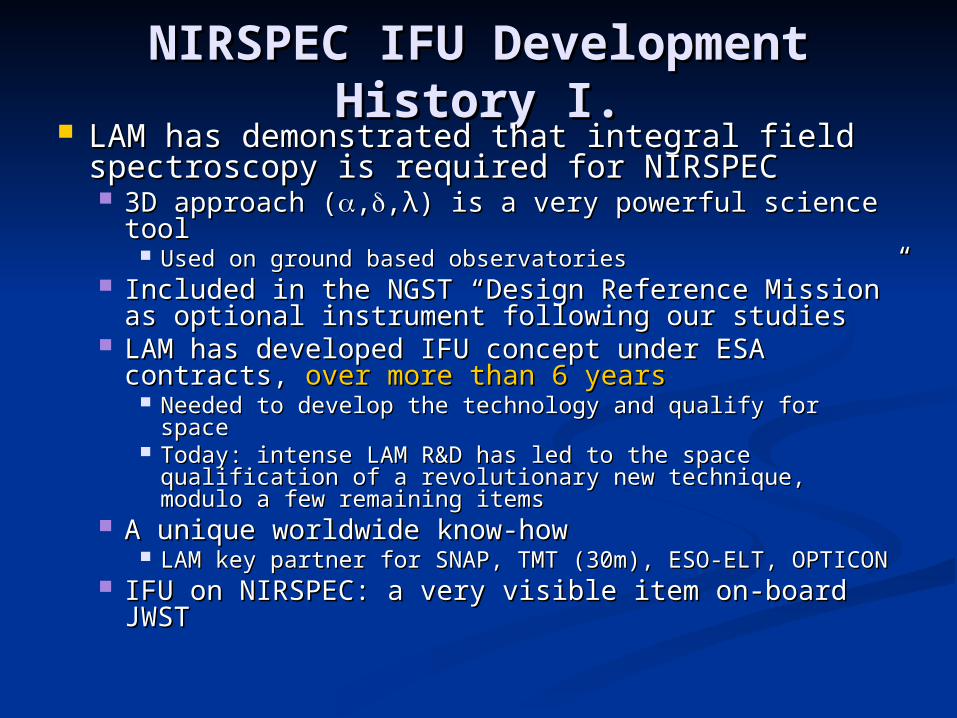
LAM has demonstrated that integral field LAM has demonstrated that integral field spectroscopy is required for NIRSPECspectroscopy is required for NIRSPEC 3D approach (3D approach (,,,,λλ) is a very powerful science tool) is a very powerful science tool
Used on ground based observatoriesUsed on ground based observatories Included in the NGST “Design Reference Mission” as Included in the NGST “Design Reference Mission” as
optional instrument following our studiesoptional instrument following our studies LAM has developed IFU concept under ESA LAM has developed IFU concept under ESA
contracts, contracts, over more than 6 yearsover more than 6 years Needed to develop the technology and qualify for spaceNeeded to develop the technology and qualify for space Today: intense LAM R&D has led to the space qualification Today: intense LAM R&D has led to the space qualification
of a revolutionary new technique, modulo a few remaining of a revolutionary new technique, modulo a few remaining itemsitems
A unique worldwide know-howA unique worldwide know-how LAM key partner for SNAP, TMT (30m), ESO-ELT, OPTICONLAM key partner for SNAP, TMT (30m), ESO-ELT, OPTICON
IFU on NIRSPEC: a very visible item on-board JWSTIFU on NIRSPEC: a very visible item on-board JWST
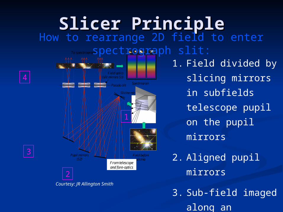
Slicer PrincipleSlicer Principle
1. Field divided by
slicing mirrors in
subfields telescope
pupil on the pupil
mirrors
2. Aligned pupil
mirrors
3. Sub-field imaged
along an entrance
slit
Field beforeslicing
Pseudo-slit
Slicing mirror (S1)
Spectrogram
Pupil mirrors(S2)
To spectrograph
Field optics (slit mirrors S3)
From telescopeand fore-optics
1
2
3
4
How to rearrange 2D field to enter spectrograph slit:
Courtesy: JR Allington Smith
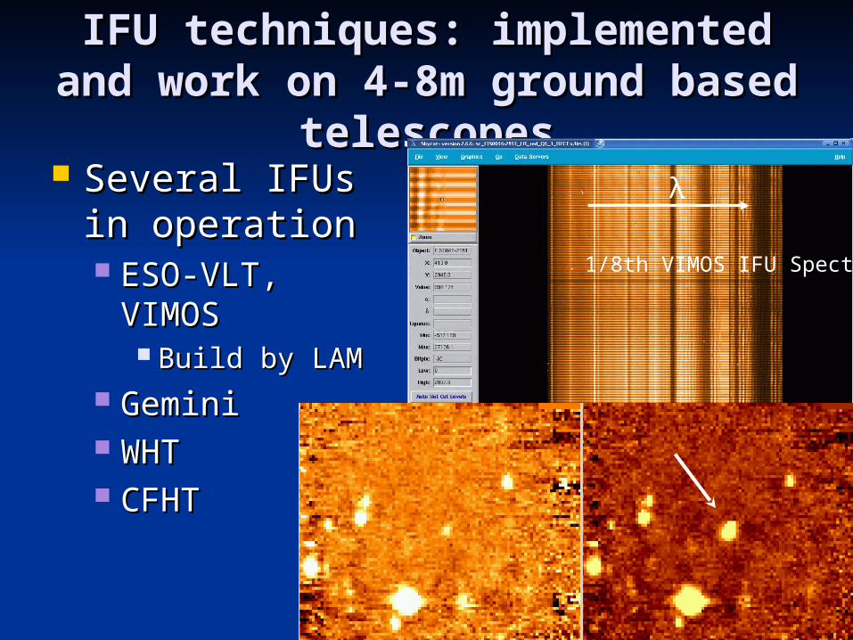
IFU techniques: implemented IFU techniques: implemented and work on 4-8m ground and work on 4-8m ground
based telescopesbased telescopes Several IFUs Several IFUs
in operationin operation ESO-VLT, ESO-VLT,
VIMOSVIMOS Build by LAMBuild by LAM
GeminiGemini WHTWHT CFHTCFHT
1/8th VIMOS IFU Spectra
λ
Key “historical” pointsKey “historical” points
LAM has created a unique robust IFU LAM has created a unique robust IFU optical designoptical design No competitor worldwide in visible - NIRNo competitor worldwide in visible - NIR
LAM has been an essential contributor to LAM has been an essential contributor to NIRSPEC design. NIRSPEC design. Optical concept from LAMOptical concept from LAM Has helped ASD to focus on proper design Has helped ASD to focus on proper design
analysis (Phase A “crisis”)analysis (Phase A “crisis”) LAM has been a key partner for ASD to LAM has been a key partner for ASD to
win NIRSPEC contractwin NIRSPEC contract Essential expertise at LAM not present at ASDEssential expertise at LAM not present at ASD
Excellent partnership over 6 yearsExcellent partnership over 6 years
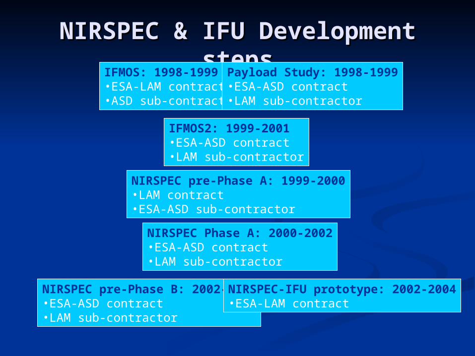
NIRSPEC & IFU Development NIRSPEC & IFU Development stepssteps
IFMOS: 1998-1999•ESA-LAM contract•ASD sub-contractor
IFMOS2: 1999-2001•ESA-ASD contract•LAM sub-contractor
NIRSPEC pre-Phase A: 1999-2000•LAM contract•ESA-ASD sub-contractor
NIRSPEC Phase A: 2000-2002•ESA-ASD contract•LAM sub-contractor
NIRSPEC pre-Phase B: 2002-2004•ESA-ASD contract•LAM sub-contractor
Payload Study: 1998-1999•ESA-ASD contract•LAM sub-contractor
NIRSPEC-IFU prototype: 2002-2004•ESA-LAM contract
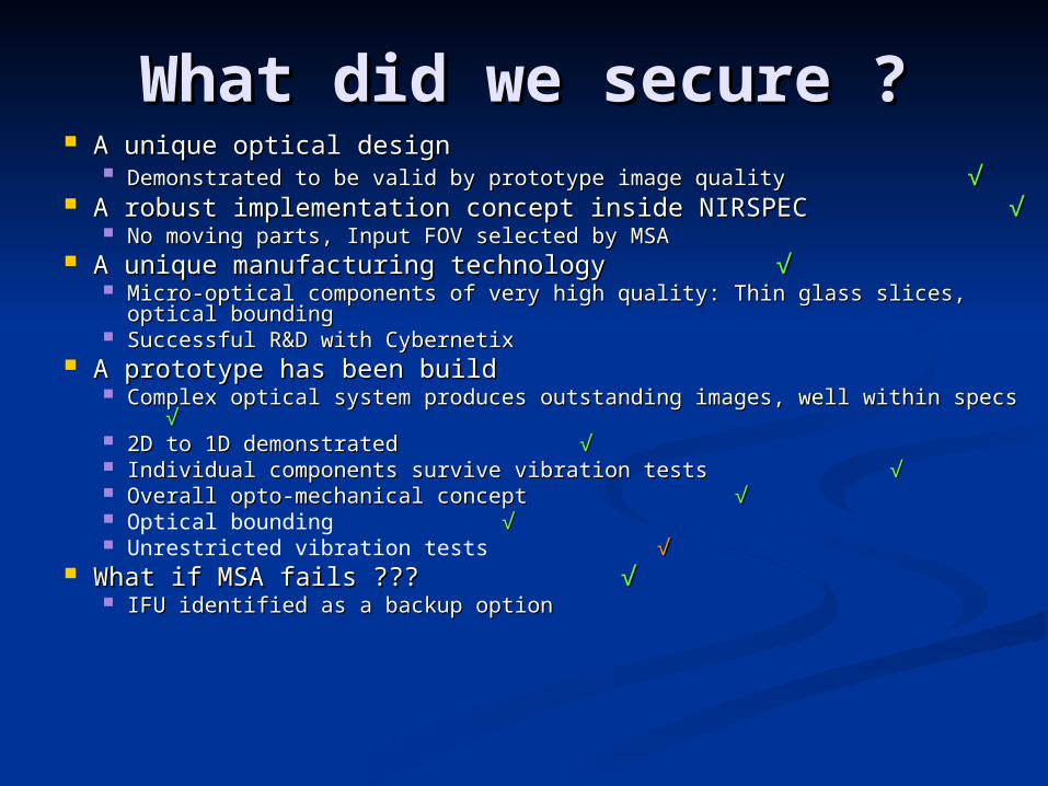
What did we secure ?What did we secure ? A unique optical designA unique optical design
Demonstrated to be valid by prototype image quality Demonstrated to be valid by prototype image quality √√ A robust implementation concept inside NIRSPECA robust implementation concept inside NIRSPEC √√
No moving parts, Input FOV selected by MSANo moving parts, Input FOV selected by MSA A unique manufacturing technologyA unique manufacturing technology √√
Micro-optical components of very high quality: Thin glass slices, optical Micro-optical components of very high quality: Thin glass slices, optical boundingbounding
Successful R&D with CybernetixSuccessful R&D with Cybernetix A prototype has been buildA prototype has been build
Complex optical system produces outstanding images, well within specs Complex optical system produces outstanding images, well within specs √√
2D to 1D demonstrated2D to 1D demonstrated √√ Individual components survive vibration testsIndividual components survive vibration tests √√ Overall opto-mechanical conceptOverall opto-mechanical concept √√ Optical bounding √√ Unrestricted vibration tests √√
What if MSA fails ???What if MSA fails ??? √√ IFU identified as a backup optionIFU identified as a backup option

What are we missing ?What are we missing ? System approachSystem approach
Simulated dynamic opto-mechanical modelSimulated dynamic opto-mechanical model Demonstrated vibration test survivalDemonstrated vibration test survival
Need to apply simulation results to notch appropriatelyNeed to apply simulation results to notch appropriately Prototype was vibrated full-on without adequate Prototype was vibrated full-on without adequate
notching ! notching ! Nevertheless, very limited breakageNevertheless, very limited breakage Lesson from prototype vibration test very valuableLesson from prototype vibration test very valuable
Increment toward full success is small Increment toward full success is small compared to existing development successescompared to existing development successes A lot has been doneA lot has been done Remaining validation work compatible with phase Remaining validation work compatible with phase
BB
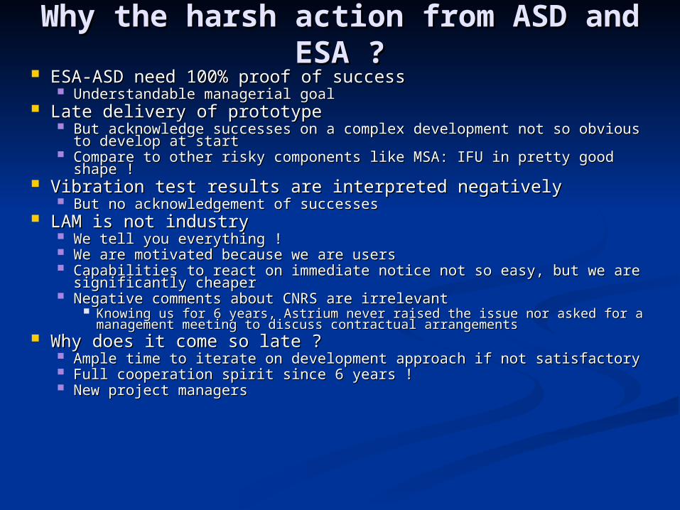
Why the harsh action from ASD Why the harsh action from ASD and ESA ?and ESA ?
ESA-ASD need 100% proof of successESA-ASD need 100% proof of success Understandable managerial goalUnderstandable managerial goal
Late delivery of prototypeLate delivery of prototype But acknowledge successes on a complex development not so obvious to But acknowledge successes on a complex development not so obvious to
develop at startdevelop at start Compare to other risky components like MSA: IFU in pretty good shape !Compare to other risky components like MSA: IFU in pretty good shape !
Vibration test results are interpreted negativelyVibration test results are interpreted negatively But no acknowledgement of successesBut no acknowledgement of successes
LAM is not industryLAM is not industry We tell you everything !We tell you everything ! We are motivated because we are usersWe are motivated because we are users Capabilities to react on immediate notice not so easy, but we are Capabilities to react on immediate notice not so easy, but we are
significantly cheapersignificantly cheaper Negative comments about CNRS are irrelevant Negative comments about CNRS are irrelevant
Knowing us for 6 years, Astrium never raised the issue nor asked for a Knowing us for 6 years, Astrium never raised the issue nor asked for a management meeting to discuss contractual arrangementsmanagement meeting to discuss contractual arrangements
Why does it come so late ?Why does it come so late ? Ample time to iterate on development approach if not satisfactoryAmple time to iterate on development approach if not satisfactory Full cooperation spirit since 6 years !Full cooperation spirit since 6 years ! New project managersNew project managers
ESA ASTRIUM concernsESA ASTRIUM concerns
ESA and Astrium presentationESA and Astrium presentation
Technical BaselineTechnical BaselineI. Start from prototypeI. Start from prototype
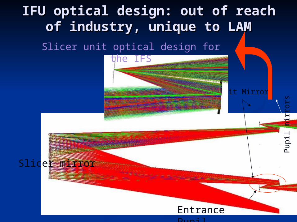
Entrance Pupil
Slicer mirror
Pupi
l mir
rors
Slit Mirrors
Slicer unit optical design for the IFS
IFU optical design: out of reach of IFU optical design: out of reach of industry, unique to LAMindustry, unique to LAM
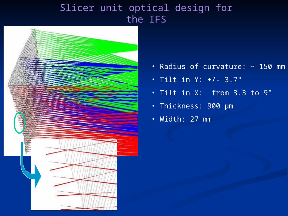
• Radius of curvature: ~ 150 mm
• Tilt in Y: +/- 3.7°
• Tilt in X: from 3.3 to 9°
• Thickness: 900 µm
• Width: 27 mm
Slicer unit optical design for the IFS
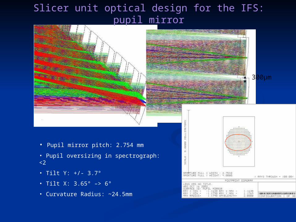
300µm
• Pupil mirror pitch: 2.754 mm
• Pupil oversizing in spectrograph: <2
• Tilt Y: +/- 3.7°
• Tilt X: 3.65° –> 6°
• Curvature Radius: ~24.5mm
Slicer unit optical design for the IFS: pupil mirror
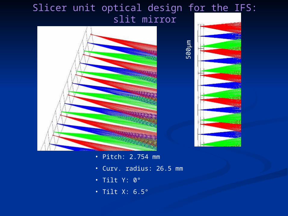
500µ
m
• Pitch: 2.754 mm
• Curv. radius: 26.5 mm
• Tilt Y: 0°
• Tilt X: 6.5°
Slicer unit optical design for the IFS: slit mirror

Image Slicer : 1st design
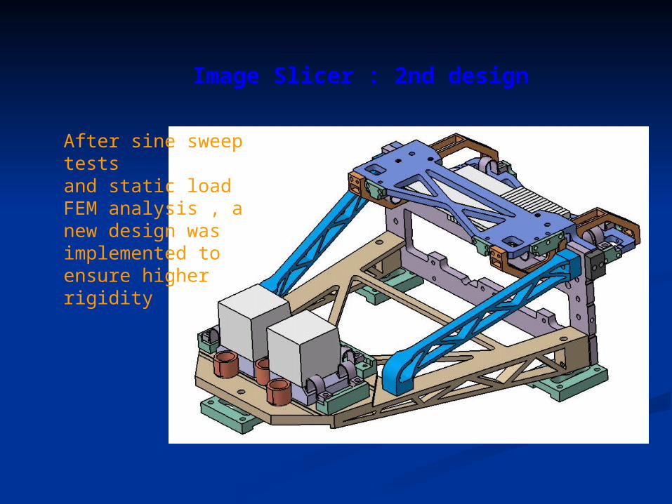
Image Slicer : 2nd design
After sine sweep testsand static load FEM analysis , a new design was implemented to ensure higher rigidity
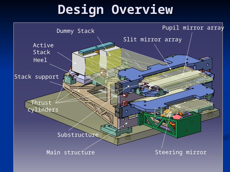
Design OverviewDesign Overview
Active Stack
Heel
Stack support
Steering mirror
Pupil mirror array
Slit mirror array
Main structure
Substructure
Thrust cylinders
Dummy Stack
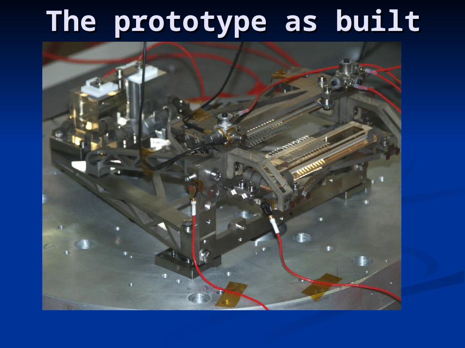
The prototype as builtThe prototype as built
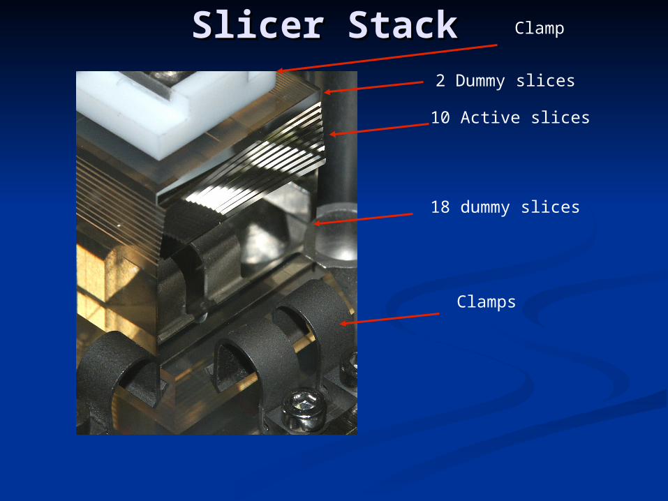
Slicer StackSlicer Stack
Clamps
18 dummy slices
10 Active slices
2 Dummy slices
Clamp
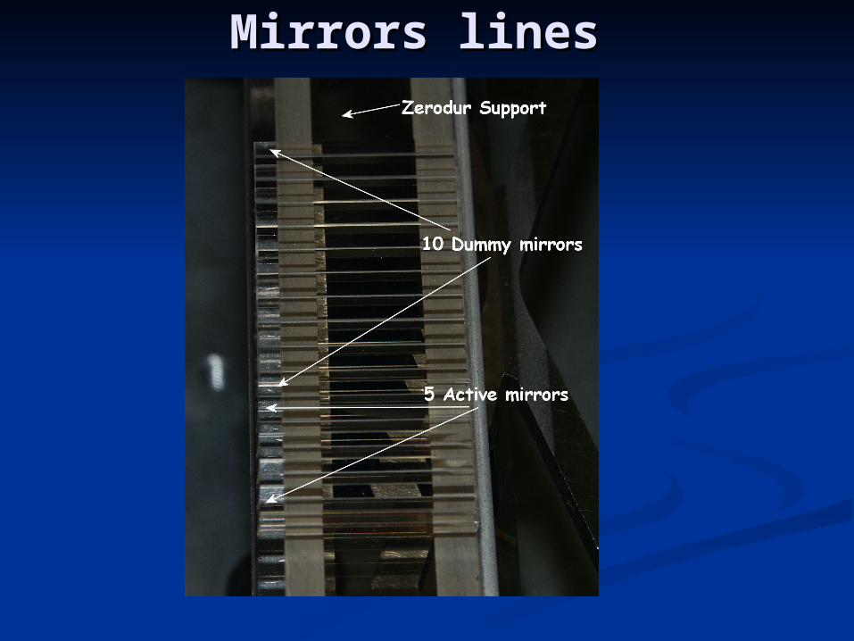
Mirrors linesMirrors lines
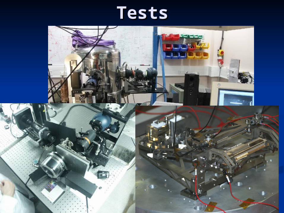
TestsTests
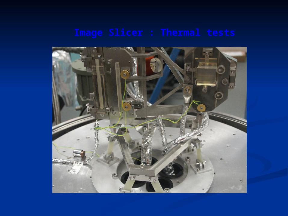
Image Slicer : Thermal tests
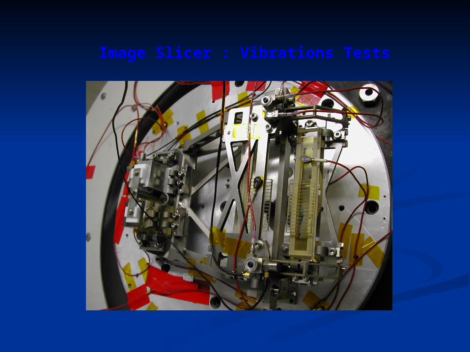
Image Slicer : Vibrations Tests

Development Development Results Results
HighlightsHighlights
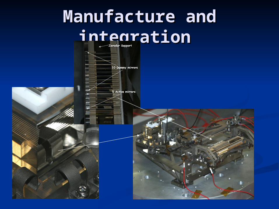
Manufacture and Manufacture and integration integration
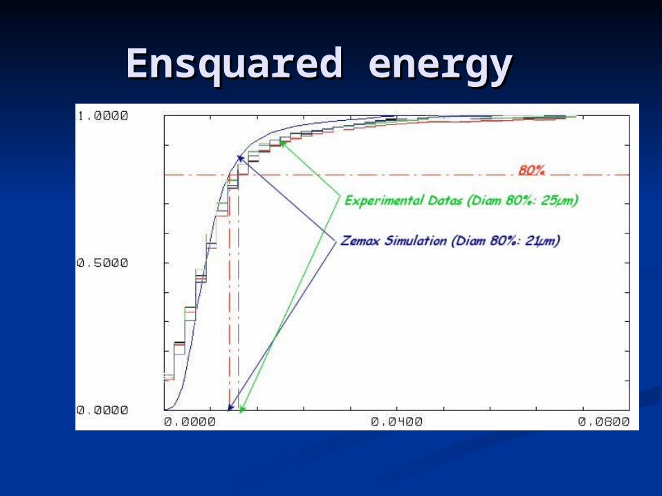
Ensquared energy Ensquared energy
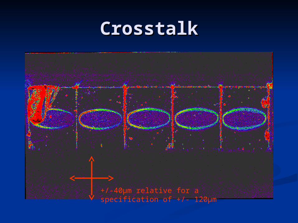
CrosstalkCrosstalk
+/-40µm relative for a specification of +/- 120µm
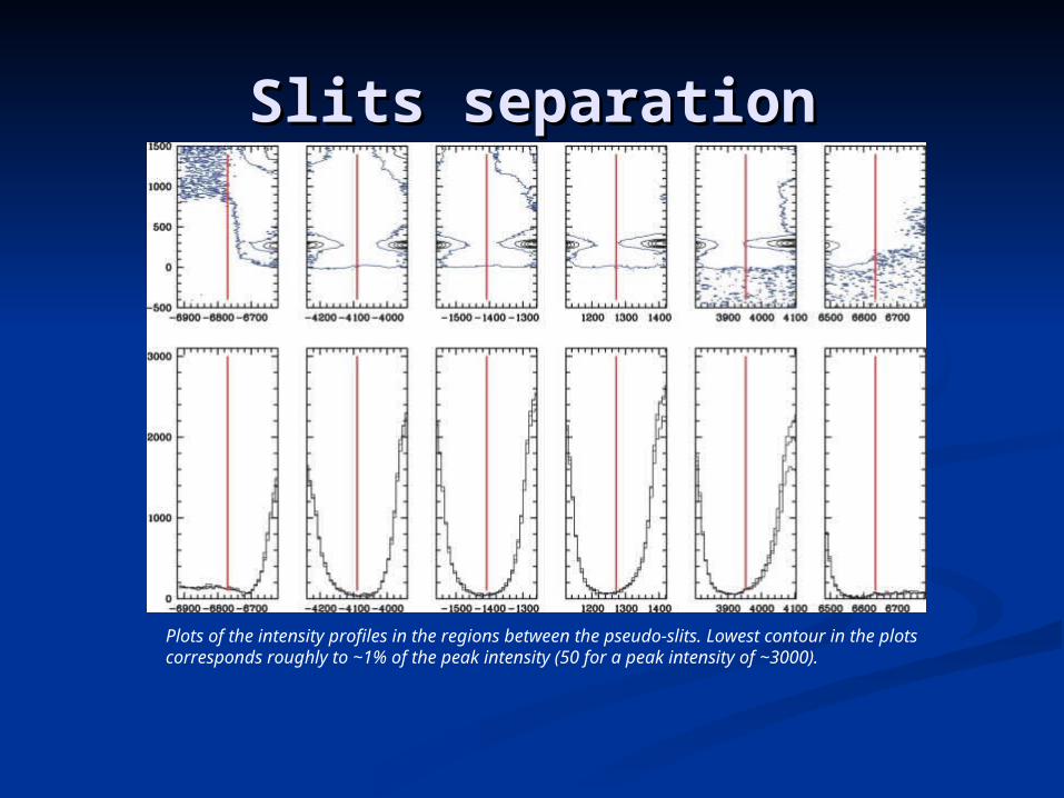
Slits separationSlits separation
Plots of the intensity profiles in the regions between the pseudo-slits. Lowest contour in the plots corresponds roughly to ~1% of the peak intensity (50 for a peak intensity of ~3000).
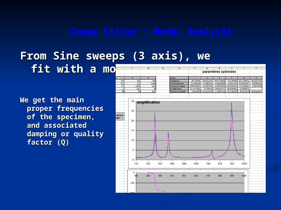
From Sine sweeps (3 axis), we From Sine sweeps (3 axis), we fit with a model of n SDOF :fit with a model of n SDOF :
Image Slicer : Modal Analysis
We get the main We get the main proper frequencies proper frequencies of the specimen, of the specimen, and associated and associated damping or quality damping or quality factor (Q)factor (Q)
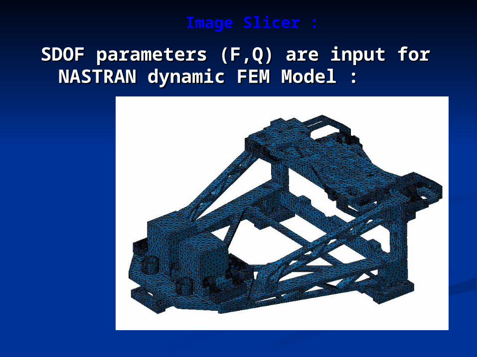
SDOF parameters (F,Q) are input for SDOF parameters (F,Q) are input for NASTRAN dynamic FEM Model :NASTRAN dynamic FEM Model :
Image Slicer :
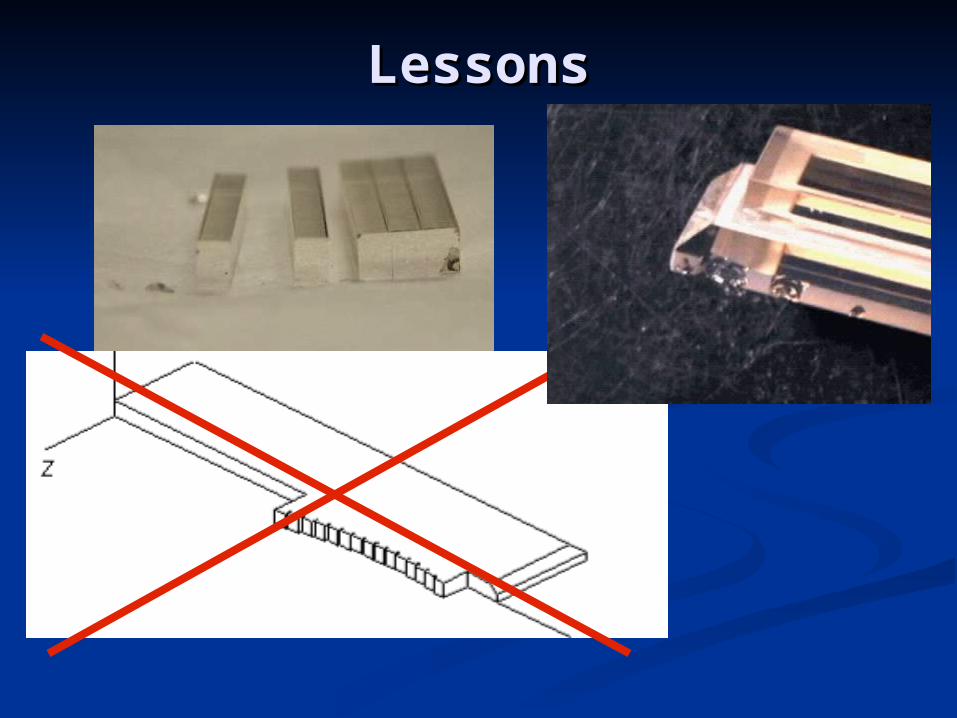
LessonsLessons
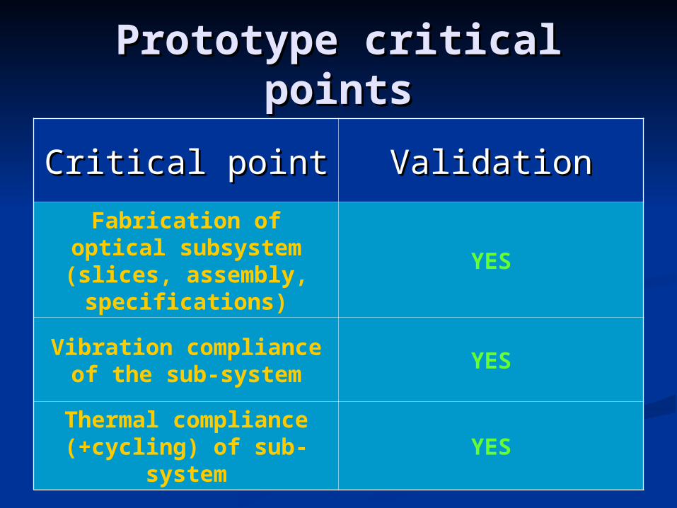
Prototype critical pointsPrototype critical points
Critical pointCritical point ValidationValidationFabrication of optical
subsystem (slices, assembly,
specifications)
YES
Vibration compliance of the sub-system
YES
Thermal compliance (+cycling) of sub-
systemYES
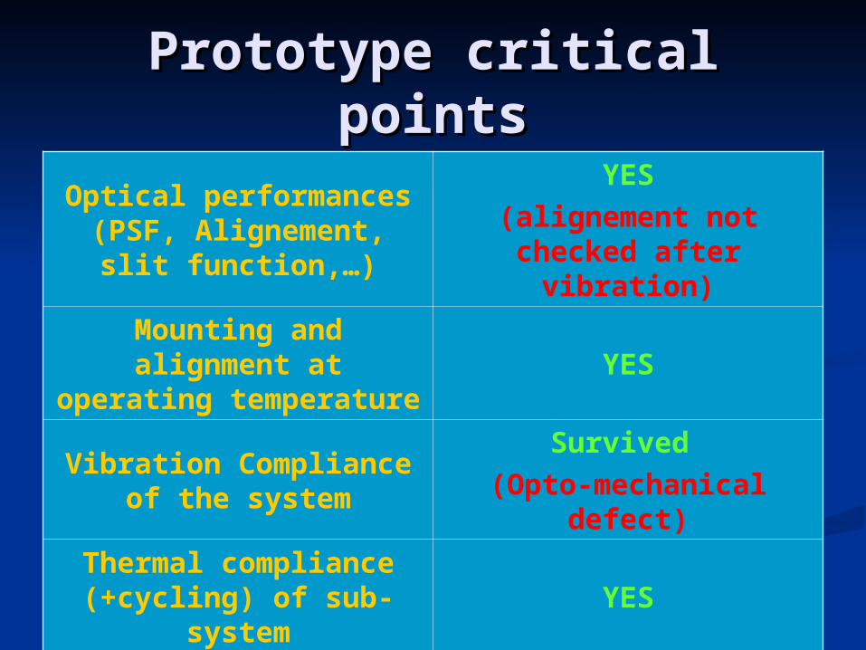
Prototype critical pointsPrototype critical points
Optical performances (PSF, Alignement, slit
function,…)
YES(alignement not checked after
vibration)
Mounting and alignment at
operating temperatureYES
Vibration Compliance of the system
Survived (Opto-mechanical
defect)
Thermal compliance (+cycling) of sub-
systemYES
Lessons Learned from the Lessons Learned from the prototype developmentprototype development
LAM Team R&T development spirit while the LAM Team R&T development spirit while the contract was more flight hardware delivery contract was more flight hardware delivery oriented ( ESA did not refocus during the study)oriented ( ESA did not refocus during the study)
LAM experience in structural dynamic analysis LAM experience in structural dynamic analysis not sufficientnot sufficient
No internal review conducted before final and No internal review conducted before final and critical vibration tests and report deliverycritical vibration tests and report delivery
Estimates of delays not properly handledEstimates of delays not properly handled LAM needs external supportLAM needs external support
But the prototype is finished and But the prototype is finished and the core technology is validatedthe core technology is validated
How to proceed for the How to proceed for the NIRSPEC-IFU development NIRSPEC-IFU development Need of phase B/C/D industrial Need of phase B/C/D industrial
management typemanagement type Need support for dynamical analysis Need support for dynamical analysis
studystudy LAM concentrates on optical LAM concentrates on optical
development and testsdevelopment and tests
Refocusing on our core Refocusing on our core activitiesactivities
InspectionInspection Flakes are located at contact area with metallic (invar) stopsFlakes are located at contact area with metallic (invar) stops Fretting corrosion marks at these locations Fretting corrosion marks at these locations
Optical parts have movedOptical parts have movedNo non-emerging cracksNo non-emerging cracks
AnalysisAnalysis Geometry of contact area is not compatible with Geometry of contact area is not compatible with
glass/metal contact criteriaglass/metal contact criteria Location of stops is not optimized to loads repartitionLocation of stops is not optimized to loads repartition QSL dimensioning is not appropriate, end despite QSL dimensioning is not appropriate, end despite
notching, as 5 sigmas levels foundnotching, as 5 sigmas levels found
SolutionsSolutions Improvement of the contact points between Zerodur and Improvement of the contact points between Zerodur and
InvarInvar Avoid contact points near the edges of the Zerodur partAvoid contact points near the edges of the Zerodur part Compute the required forces to maintain the optics, then Compute the required forces to maintain the optics, then
increase the force of springsincrease the force of springs
Image Slicer : post-vibration Expertise
SolutionsSolutions Recompute force appliedRecompute force applied
Not strong enoughNot strong enough Increase by x2-3Increase by x2-3
Groove in metalGroove in metal Beveled edge on glassBeveled edge on glass Clamp on back supportClamp on back support Fused silica instead of zerodur ?Fused silica instead of zerodur ?
Less brittleLess brittle Glass to metalGlass to metal
Soft materialSoft material GoldGold
Fixed spherical contactFixed spherical contact Self adjusting spherical washerSelf adjusting spherical washer
Image Slicer : support solutions
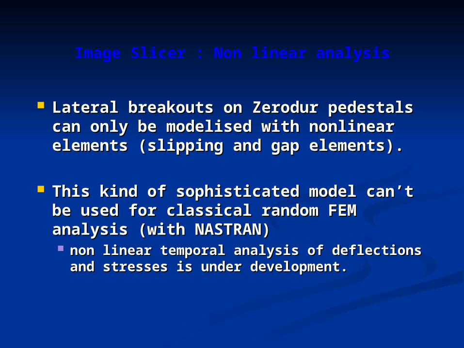
Lateral breakouts on Zerodur pedestals Lateral breakouts on Zerodur pedestals can only be modelised with nonlinear can only be modelised with nonlinear elements (slipping and gap elements).elements (slipping and gap elements).
This kind of sophisticated model can’t This kind of sophisticated model can’t be used for classical random FEM be used for classical random FEM analysis (with NASTRAN)analysis (with NASTRAN) non linear temporal analysis of deflections non linear temporal analysis of deflections
and stresses is under development.and stresses is under development.
Image Slicer : Non linear analysis
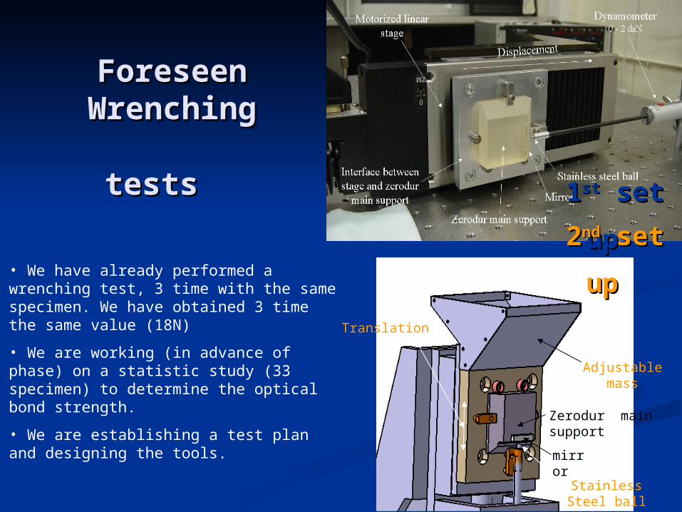
Foreseen Foreseen Wrenching Wrenching
teststests
mirror
Zerodur main support
Adjustable mass
Translation
Stainless Steel ball(thrust)
• We have already performed a wrenching test, 3 time with the same specimen. We have obtained 3 time the same value (18N)
• We are working (in advance of phase) on a statistic study (33 specimen) to determine the optical bond strength.
• We are establishing a test plan and designing the tools.
11stst set set
upup 22ndnd set set
upup
Technical BaselineTechnical BaselineII. Proposed designII. Proposed design
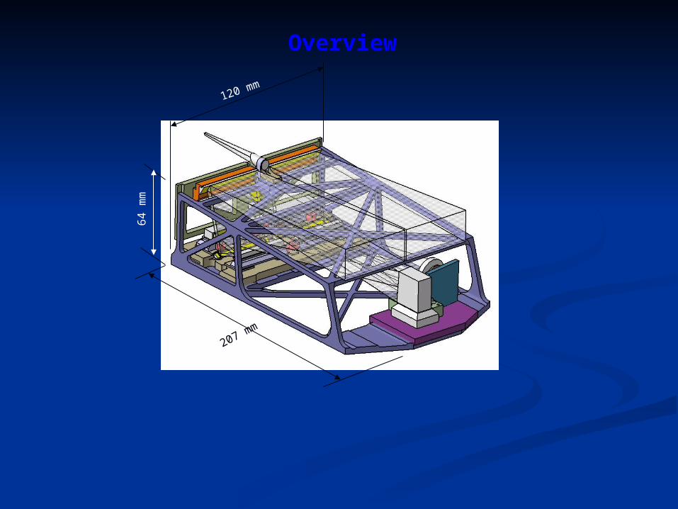
120 mm
64
mm
207 mm
Overview
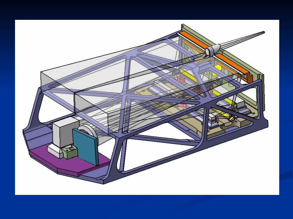
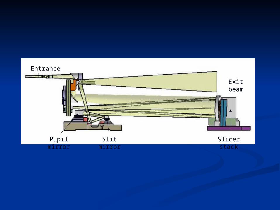
Entrance beam
Slicer stackPupil mirror Slit mirror
Exit beam
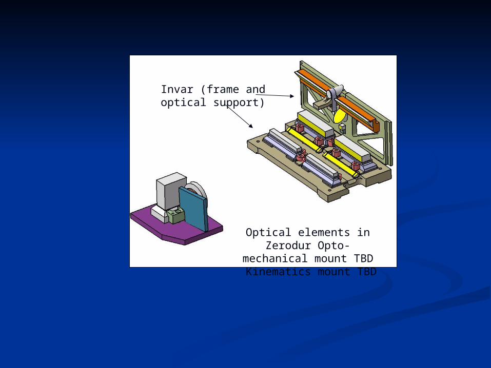
Invar (frame and optical support)
Optical elements in Zerodur Opto-mechanical mount TBD
Kinematics mount TBD
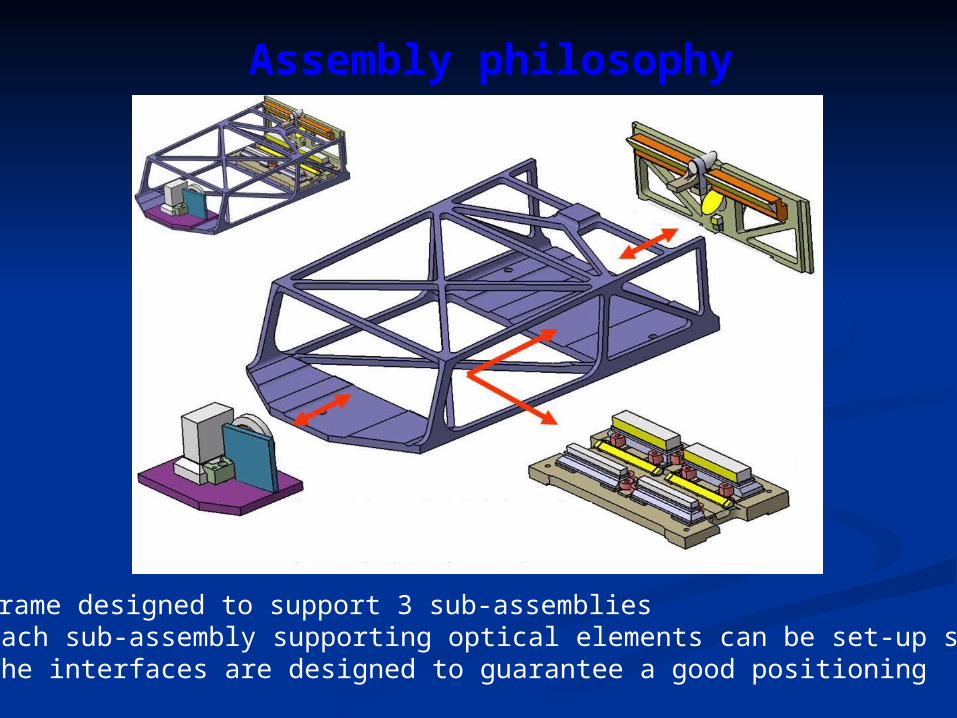
Assembly philosophy
• Frame designed to support 3 sub-assemblies• Each sub-assembly supporting optical elements can be set-up separately• The interfaces are designed to guarantee a good positioning

Weight: Mechanics 810 gr baffling 250 gr optics 70 gr thermal sensors 12 gr
Total 1212gr
Weight
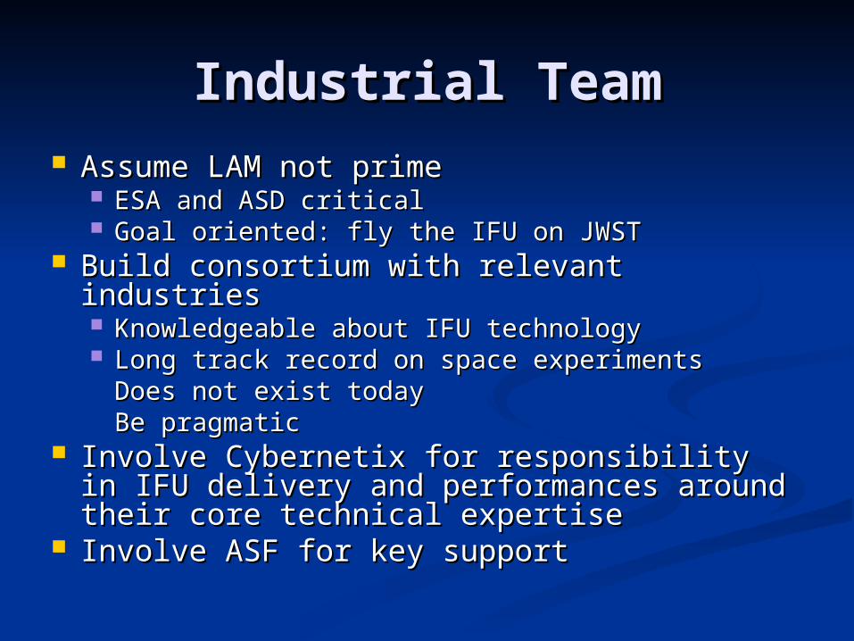
Industrial TeamIndustrial Team Assume LAM not primeAssume LAM not prime
ESA and ASD criticalESA and ASD critical Goal oriented: fly the IFU on JWSTGoal oriented: fly the IFU on JWST
Build consortium with relevant industriesBuild consortium with relevant industries Knowledgeable about IFU technologyKnowledgeable about IFU technology Long track record on space experimentsLong track record on space experiments
Does not exist todayDoes not exist todayBe pragmaticBe pragmatic
Involve Cybernetix for responsibility in Involve Cybernetix for responsibility in IFU delivery and performances around IFU delivery and performances around their core technical expertisetheir core technical expertise
Involve ASF for key supportInvolve ASF for key support
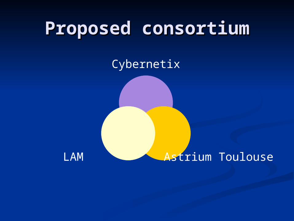
Proposed consortiumProposed consortium
Cybernetix
Astrium ToulouseLAM
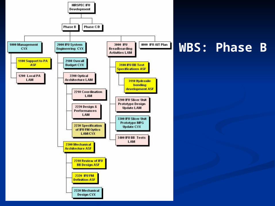
WBS: Phase B
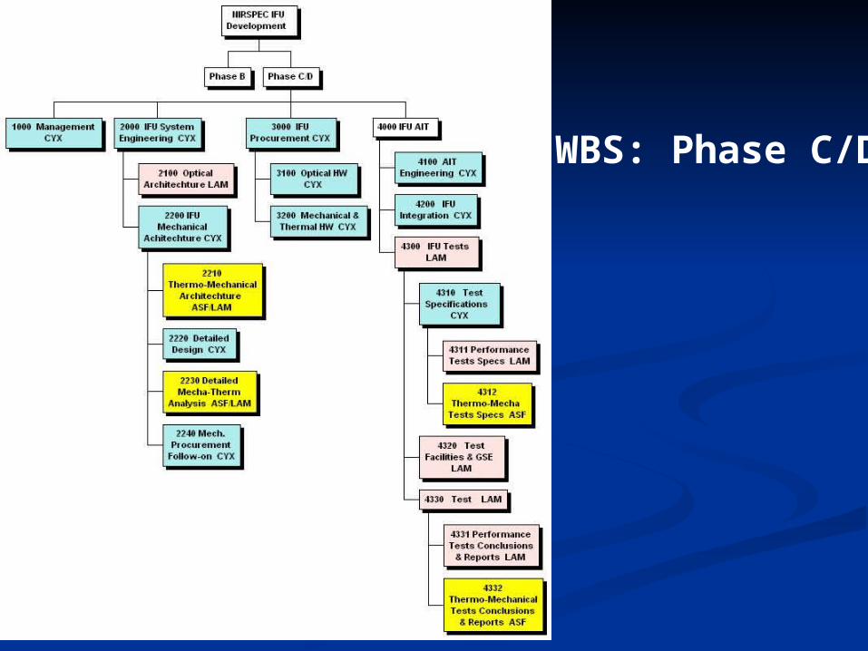
WBS: Phase C/D
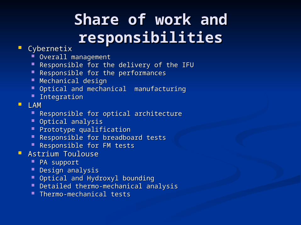
Share of work and Share of work and responsibilitiesresponsibilities
CybernetixCybernetix Overall managementOverall management Responsible for the delivery of the IFUResponsible for the delivery of the IFU Responsible for the performances Responsible for the performances Mechanical designMechanical design Optical and mechanical manufacturingOptical and mechanical manufacturing IntegrationIntegration
LAMLAM Responsible for optical architectureResponsible for optical architecture Optical analysisOptical analysis Prototype qualificationPrototype qualification Responsible for breadboard testsResponsible for breadboard tests Responsible for FM testsResponsible for FM tests
Astrium ToulouseAstrium Toulouse PA supportPA support Design analysisDesign analysis Optical and Hydroxyl boundingOptical and Hydroxyl bounding Detailed thermo-mechanical analysisDetailed thermo-mechanical analysis Thermo-mechanical testsThermo-mechanical tests
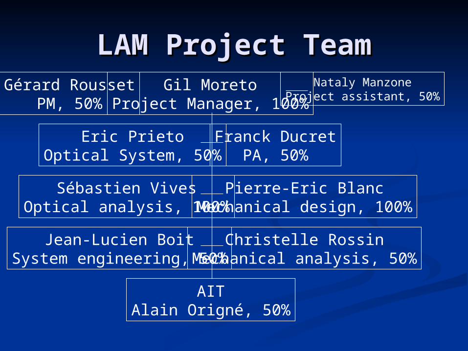
LAM Project TeamLAM Project TeamGil Moreto
Project Manager, 100%
Eric PrietoOptical System, 50%
Franck DucretPA, 50%
Sébastien VivesOptical analysis, 100%
Nataly ManzoneProject assistant, 50%
Pierre-Eric BlancMechanical design, 100%
Jean-Lucien BoitSystem engineering, 50%
Christelle RossinMechanical analysis, 50%
AITAlain Origné, 50%
Gérard RoussetPM, 50%
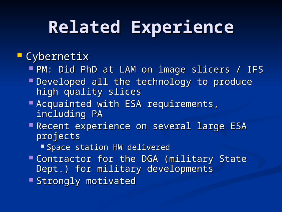
Related ExperienceRelated Experience CybernetixCybernetix
PM: Did PhD at LAM on image slicers / IFSPM: Did PhD at LAM on image slicers / IFS Developed all the technology to produce high Developed all the technology to produce high
quality slicesquality slices Acquainted with ESA requirements, including Acquainted with ESA requirements, including
PAPA Recent experience on several large ESA Recent experience on several large ESA
projectsprojects Space station HW deliveredSpace station HW delivered
Contractor for the DGA (military State Dept.) Contractor for the DGA (military State Dept.) for military developments for military developments
Strongly motivatedStrongly motivated
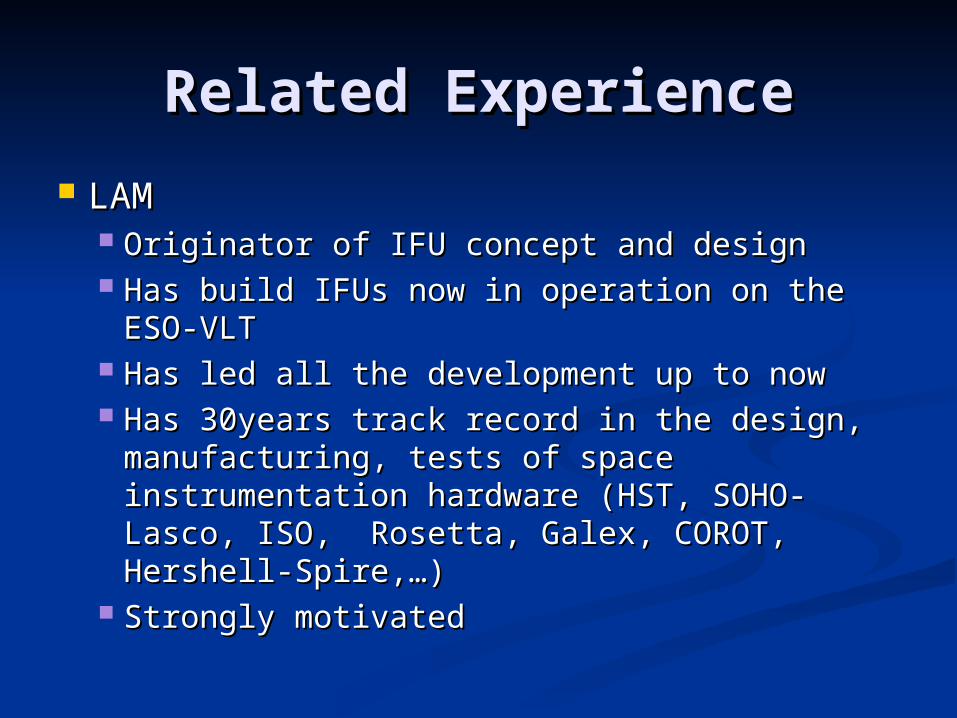
Related ExperienceRelated Experience
LAMLAM Originator of IFU concept and designOriginator of IFU concept and design Has build IFUs now in operation on the ESO-Has build IFUs now in operation on the ESO-
VLTVLT Has led all the development up to nowHas led all the development up to now Has 30years track record in the design, Has 30years track record in the design,
manufacturing, tests of space manufacturing, tests of space instrumentation hardware (HST, SOHO-instrumentation hardware (HST, SOHO-Lasco, ISO, Rosetta, Galex, COROT, Lasco, ISO, Rosetta, Galex, COROT, Hershell-Spire,…)Hershell-Spire,…)
Strongly motivatedStrongly motivated
Related ExperienceRelated Experience
Astrium ToulouseAstrium Toulouse You know themYou know them Strongly motivatedStrongly motivated
Design & development Design & development approachapproach
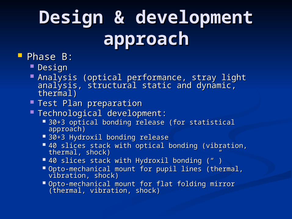
Phase B:Phase B: DesignDesign Analysis (optical performance, stray light Analysis (optical performance, stray light
analysis, structural static and dynamic, thermal)analysis, structural static and dynamic, thermal) Test Plan preparationTest Plan preparation Technological development:Technological development:
30+3 optical bonding release (for statistical approach)30+3 optical bonding release (for statistical approach) 30+3 Hydroxil bonding release 30+3 Hydroxil bonding release 40 slices stack with optical bonding (vibration, thermal, 40 slices stack with optical bonding (vibration, thermal,
shock)shock) 40 slices stack with Hydroxil bonding (“”)40 slices stack with Hydroxil bonding (“”) Opto-mechanical mount for pupil lines (thermal, Opto-mechanical mount for pupil lines (thermal,
vibration, shock)vibration, shock) Opto-mechanical mount for flat folding mirror (thermal, Opto-mechanical mount for flat folding mirror (thermal,
vibration, shock)vibration, shock)
Design & development Design & development approachapproach
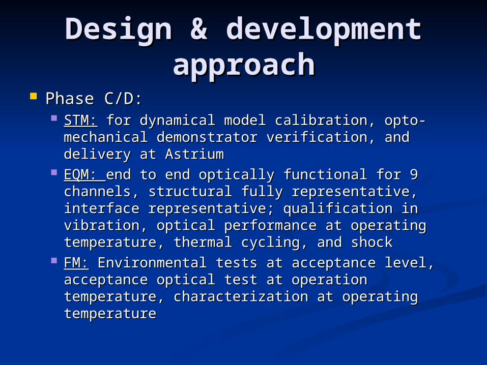
Phase C/D:Phase C/D: STM:STM: for dynamical model calibration, opto- for dynamical model calibration, opto-
mechanical demonstrator verification, and mechanical demonstrator verification, and delivery at Astriumdelivery at Astrium
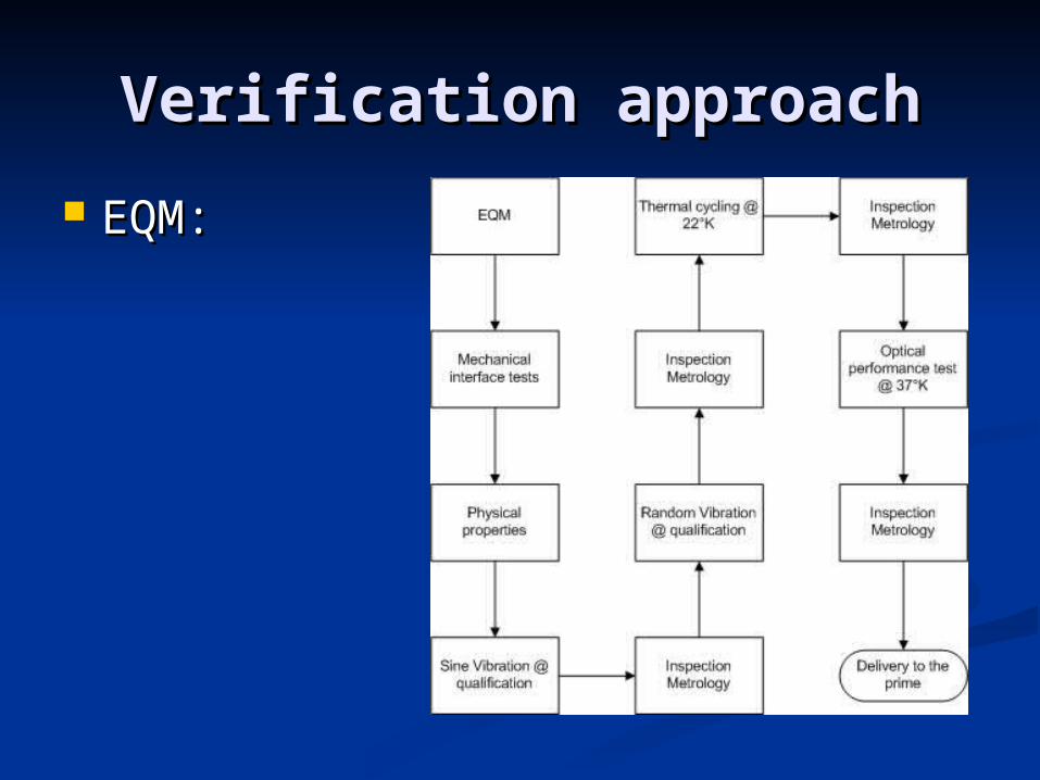
EQM: EQM: end to end optically functional for 9 end to end optically functional for 9 channels, structural fully representative, channels, structural fully representative, interface representative; qualification in interface representative; qualification in vibration, optical performance at operating vibration, optical performance at operating temperature, thermal cycling, and shocktemperature, thermal cycling, and shock
FM:FM: Environmental tests at acceptance level, Environmental tests at acceptance level, acceptance optical test at operation temperature, acceptance optical test at operation temperature, characterization at operating temperaturecharacterization at operating temperature
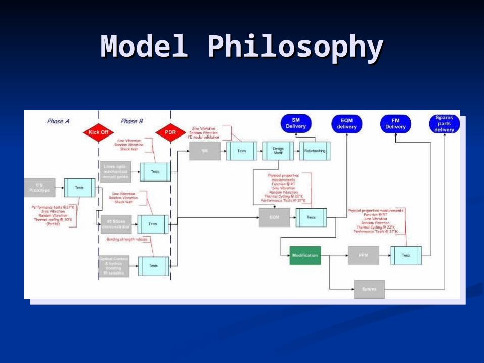
Model PhilosophyModel Philosophy
Technology development Technology development plan plan
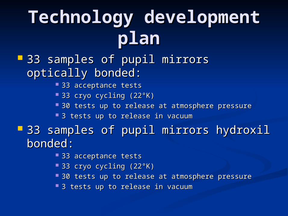
33 samples of pupil mirrors optically 33 samples of pupil mirrors optically bonded:bonded:
33 acceptance tests33 acceptance tests 33 cryo cycling (22°K)33 cryo cycling (22°K) 30 tests up to release at atmosphere pressure30 tests up to release at atmosphere pressure 3 tests up to release in vacuum3 tests up to release in vacuum
33 samples of pupil mirrors hydroxil 33 samples of pupil mirrors hydroxil bonded:bonded:
33 acceptance tests33 acceptance tests 33 cryo cycling (22°K)33 cryo cycling (22°K) 30 tests up to release at atmosphere pressure30 tests up to release at atmosphere pressure 3 tests up to release in vacuum3 tests up to release in vacuum
Technology development Technology development plan plan
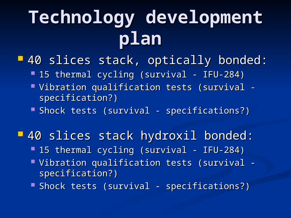
40 slices stack, optically bonded:40 slices stack, optically bonded: 15 thermal cycling (survival - IFU-284)15 thermal cycling (survival - IFU-284) Vibration qualification tests (survival - Vibration qualification tests (survival -
specification?)specification?) Shock tests (survival - specifications?)Shock tests (survival - specifications?)
40 slices stack hydroxil bonded:40 slices stack hydroxil bonded: 15 thermal cycling (survival - IFU-284)15 thermal cycling (survival - IFU-284) Vibration qualification tests (survival - Vibration qualification tests (survival -
specification?)specification?) Shock tests (survival - specifications?)Shock tests (survival - specifications?)
Technology development Technology development plan plan
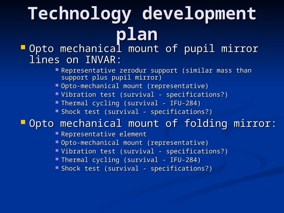
Opto mechanical mount of pupil mirror Opto mechanical mount of pupil mirror lines on INVAR:lines on INVAR:
Representative zerodur support (similar mass than support Representative zerodur support (similar mass than support plus pupil mirror)plus pupil mirror)
Opto-mechanical mount (representative)Opto-mechanical mount (representative) Vibration test (survival - specifications?)Vibration test (survival - specifications?) Thermal cycling (survival - IFU-284)Thermal cycling (survival - IFU-284) Shock test (survival - specifications?)Shock test (survival - specifications?)
Opto mechanical mount of folding mirror:Opto mechanical mount of folding mirror: Representative elementRepresentative element Opto-mechanical mount (representative)Opto-mechanical mount (representative) Vibration test (survival - specifications?)Vibration test (survival - specifications?) Thermal cycling (survival - IFU-284)Thermal cycling (survival - IFU-284) Shock test (survival - specifications?)Shock test (survival - specifications?)
Product Breakdown / Product Breakdown / procurement approachprocurement approach
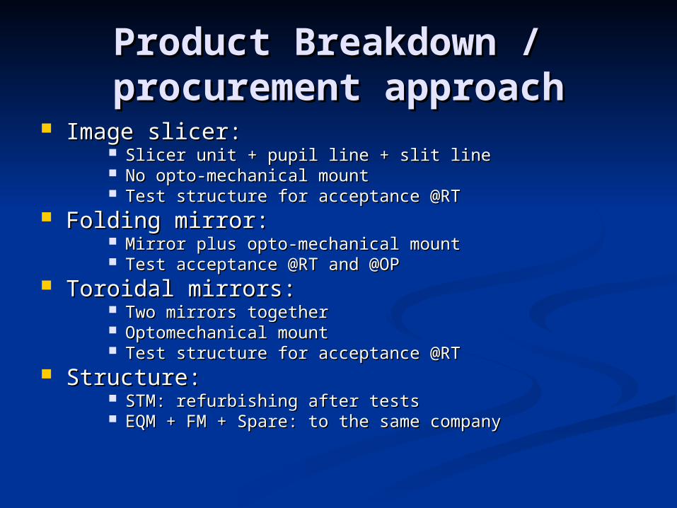
Image slicer:Image slicer: Slicer unit + pupil line + slit lineSlicer unit + pupil line + slit line No opto-mechanical mountNo opto-mechanical mount Test structure for acceptance @RTTest structure for acceptance @RT
Folding mirror:Folding mirror: Mirror plus opto-mechanical mountMirror plus opto-mechanical mount Test acceptance @RT and @OPTest acceptance @RT and @OP
Toroidal mirrors:Toroidal mirrors: Two mirrors togetherTwo mirrors together Optomechanical mountOptomechanical mount Test structure for acceptance @RTTest structure for acceptance @RT
Structure:Structure: STM: refurbishing after testsSTM: refurbishing after tests EQM + FM + Spare: to the same companyEQM + FM + Spare: to the same company
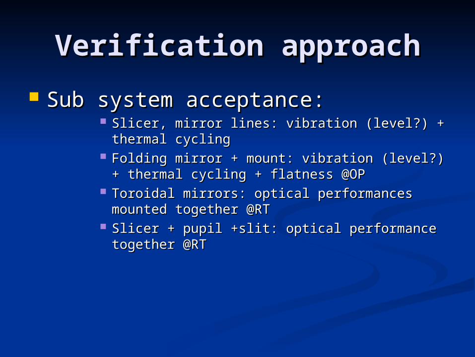
Verification approachVerification approach
Sub system acceptance:Sub system acceptance: Slicer, mirror lines: vibration (level?) + thermal Slicer, mirror lines: vibration (level?) + thermal
cyclingcycling Folding mirror + mount: vibration (level?) + Folding mirror + mount: vibration (level?) +
thermal cycling + flatness @OPthermal cycling + flatness @OP Toroidal mirrors: optical performances mounted Toroidal mirrors: optical performances mounted
together @RTtogether @RT Slicer + pupil +slit: optical performance together Slicer + pupil +slit: optical performance together
@RT@RT
Verification approachVerification approach
EQM:EQM:

Verification approachVerification approach
FM:FM:
PlanningPlanning
KO: Nov 30thKO: Nov 30th PDR: Sept 05PDR: Sept 05 In phase with general NIRSPEC In phase with general NIRSPEC
planningplanning