newsletter - enginsoft · 3 - newsletter enginsoft year 10 n°2 flash flash the ambition of us...
TRANSCRIPT

010100101110101001110101100101001101110010100101010100101110101001110101100101001
101110
01
0100101001010010
1010
10010111011001
011 Newsletter
Simulation Based Engineering & SciencesYear n°2 Summer 201310
Complete Simulation and Optimizationof the Production Process of aBearing Ring in 100CR6 Steel
QCDC connector design on a FPSO unit
Optimization of a Water System Supply
Electromagnetic Interference between High VoltageLines and Pipelines
Process-product integration to study HPDC diethermo-mechanical behavior
Stamping Dies for Vehicle Body Parts
FEM investigation for third generation photovoltaics

CAEPOSTER AWARD
21
October
2013
INTERNATIONAL
www.caeconference.comFor more information, please visit:
During the 2013 International CAE Conference – taking place on October 21st - 22nd in Lazise (VR), Italy - EnginSoft will be promoting and sponsoring (for the second year in a row) the "CAE Poster Award", a competition dedicated to the best case studies that highlight novel, innovative CAE applications.
The “CAE Poster Award” is part of the EnginSoft CAE Cultural Promotion Program, originally conceived in order to improve the correct use of simulation tools, and to foster the growth of the CAE analysts community.
The competition is open to students, graduated students, researchers and professors from both universities and research centers.
Participation is free – and the best five posters will be awarded with a tablet.
Promoted by

3 - Newsletter EnginSoft Year 10 n°2 Flash
FLASHThe ambition of us engineers, our role is to always think ahead, to create new and sustainable designs, to innovate! To achieve all this, we have to broaden our horizons and deepen our expertise constantly. We also need to further develop our soft skills in communication and networking to complement our analytical knowledge.I am delighted to invite you to the International CAE Conference that EnginSoft will host on 21st and 22nd October in Pacengo del Garda, Verona. You can be certain that our annual summit of experts from Italy, Europe and around the world will be worthwhile your time. It will offer you a diverse and most efficient platform to update yourself on the state-of-the-art of CAE and Simulation. Our agenda of visionary keynote lectures, a wide range of technical presentations, as well as users’ meetings, will be completed by the accompanying hard-and software exhibition and the CAE Poster Award that highlights novel and innovative CAE applications. As a premiere, the Aerospace & Defense Week will be launched on the occasion of the Conference.This Newsletter gives you an outlook on some of the topics that will be discussed in Pacengo del Garda. From the Oil&Gas sector, we hear about a new connector design for a floating production storage and offloading unit. Tozzi Renewable Energy presents an overview on their FEM investigations for the new generation DSSC solar cells. Muraro Spa outlines their latest design and production for a Bearing Ring, while EnginSoft Padova updates us on numerical process optimization. ANSYS APDL and ANSYS Maxwell have been used in an advanced FEM approach to analyze electromagnetic interferences. Mr. Shuji Abe of NISSAN MOTOR talks to us about his work and the use of ADVENTURECluster. The Université d’Aix-Marseille and EnginSoft France present an optimization strategy and the coupling of modeFRONTIER with Flowmaster. We also hear about Openeering’s paper “An aeraulic toolbox for Xcos” and the hybrid UAV made in Turin.
It is a great honor for us to present some of Federico Faggin’s work in this edition. Dr Faggin was responsible for the design and development of the first microprocessor. In 2010, he and the Intel team received the “National Medal of Technology and Innovation” from President Barak Obama.Our software news cover the modeFRONTER 4.5 test drive, its integration with Sculptor and the powerful capabilities of ANSYS Workbench. We introduce ESAComp 4.4.1, LIONsolver, as well as PlanetX and the new TestPaks®, which users can now order from DatapointLabs. We speak about our partnership with SAEN, an Italian foundry that counts on Magma and ANSYS to perfect its multidisciplinary simulation competencies.Further articles feature the latest news on the Osservatorio GeCo, the Professional Simulation Engineer Competency Tracker and EnginSoft Germany’s presentation at the RICARDO European User Conference.
Be inspired about CAE and Simulation – Please share your knowledge with us and experts from around the world. We look forward to welcoming you to Pacengo and the charming Lake Garda region this October!
Stefano OdorizziEditor in chief

6 QCDC connector design on a FPSO unit
8 FEM investigation for third generation photovoltaics
10 Complete Simulation and Optimization of the Production Process of a Bearing Ring in 100CR6 Steel
15 Process-product integration to study HPDC die thermo-mechanical behavior
19 Analysis of Strength and Rigidity regarding the Stamping Dies for Vehicle Body Parts using Ultra-large-scale Structural Analysis Tools
23 An Aeraulic Toolbox for XCOS
26 Optimization of a Water System Supply
29 Electromagnetic Interference between High Voltage Lines and Pipelines: an Advanced FEM Approach
32 Hybrid UAV made in Turin. The “Glider Project”
38 Dal primo Microprocessore al Computer Quantico Intervista al Prof. Faggin
42 modeFRONTER 4.5 test drive: pushing the boundaries of multidisciplinary optimization
Contents
Sommario - Contents
Newsletter EnginSoft Year 10 n°2 - 4
QDC connector design on a FPSO unit
www.caeconference.com
21 | 22 OCTOBER 2013
Pacengo del GardaVerona - Italy
Hotel Parchi del GardaVia Brusá, località PacengoLazise (VR)Tel. +39 045 6499611www.hotelparchidelgarda.it
INTERNATIONAL CAE CONFERENCE-INFOLINE [email protected] Tel. +39 0461 915391
ONE OF THE MOST RELEVANTEVENT IN EUROPE ONSIMULATION BASED
ENGINEERING AND SCIENCES
LET’S SIMULATE THE WORLD OF THE FUTURE
The EnginSoft Newsletter editions contain references to the following products which are trademarks or registered trademarks of their respective owners:
ANSYS, ANSYS Workbench, AUTODYN, CFX, FLUENT and any and all ANSYS, Inc. brand, product, service and feature names, logos and slogans are registered trademarks or trademarks of ANSYS, Inc. or its subsidiaries in the United States or other countries. [ICEM CFD is a trademark used by ANSYS, Inc. under license]. (www.ansys.com) modeFRONTIER is a trademark of ESTECO Spa (www.esteco.com)
Flowmaster is a registered trademark of Menthor Graphics in the USA (www.flowmaster.com)
MAGMASOFT is a trademark of MAGMA GmbH (www.magmasoft.de)
CETOL6 is a trademark of Sigmetrix (www.sigmetrix.com)
ADVENTURECluster is a product by Allied Engineering Corporation, the SCSK group company (www.scsk.jp)
XCOS is a trademark of Scilab Enterprises S.A.S. (www.scilab.org)
Sculptor is a trademark of Optimal Solutions Software, LLC (gosculptor.com)
ESAComp is a trademark of Componeering Inc. (www.esacomp.com)
Lionsolver is a trademark of Lionsolver Inc. (www.lionsolver.com)
PlanetsX is a trademark of Cybernet Systems CO., LTD. (www.cybernet.co.jp)
CASE HISTORIES
INTERVIEWS
SOFTWARE UPDATE
CAE Conference 2013The annual appointment on Simulation Based Engineering & Sciences

44 Tool di meshatura della piattaforma ANSYS Workbench
46 Esacomp 4.4.1, nuovi strumenti per la progettazione preliminare di strutture in materiale composito
48 Lionsolver Inc. “Machine Learning Approach”to Smartphone Data Garners $10,000 First Prizein The Michael J. Fox Foundation Parkinson’s Data Challenge
49 Injection Molding CAE System “PlanetsX” joins DatapointLabs’ TestPaks® Alliance Program to improve the system for overseas users
50 Le competenze multidisciplinari di simulazione nella partnership con la fonderia SAEN
51 The PSE Competency Tracker: a competence management system for the CAE industry
52 La gestione della progettazione nelle imprese italiane: risultati dalla ricerca dell’Osservatorio GeCo
54 Noise and Back-Pressure Reduction of Automotive End-Muffler at Ricardo European User Conference
56 Mechanical Council Meeting 2013
57 Il Trattore del Futuro in scena al Museo SAME di Treviglio
58 Event Calendar
59 International CAE Conference 2013
Contents
Newsletter EnginSoftYear 10 n°2 - Summer 2013To receive a free copy of the next EnginSoft Newsletters, please contact our Marketing office at: [email protected]
All pictures are protected by copyright. Any reproduction of these pictures in any media and by any means is forbidden unless written authorization by EnginSoft has been obtained beforehand. ©Copyright EnginSoft Newsletter.
AdvertisementFor advertising opportunities, please contact our Marketing office at: [email protected]
EnginSoft S.p.A.24126 BERGAMO c/o Parco Scientifico TecnologicoKilometro Rosso - Edificio A1, Via Stezzano 87Tel. +39 035 368711 • Fax +39 0461 97921550127 FIRENZE Via Panciatichi, 40Tel. +39 055 4376113 • Fax +39 0461 97921635129 PADOVA Via Giambellino, 7Tel. +39 049 7705311 • Fax +39 0461 97921772023 MESAGNE (BRINDISI) Via A. Murri, 2 - Z.I.Tel. +39 0831 730194 • Fax +39 0461 97922438123 TRENTO fraz. Mattarello - Via della Stazione, 27Tel. +39 0461 915391 • Fax +39 0461 97920110133 TORINO Corso Moncalieri, 223Tel. +39 011 3473987 • Fax +39 011 3473987
www.enginsoft.it - www.enginsoft.come-mail: [email protected]
COMPANY INTERESTSCONSORZIO TCNwww.consorziotcn.it • www.improve.it
EnginSoft GmbH - GermanyEnginSoft UK - United KingdomEnginSoft France - FranceEnginSoft Nordic - Swedenwww.enginsoft.com
Cascade Technologieswww.cascadetechnologies.comReactive Searchwww.reactive-search.comSimNumericawww.simnumerica.itM3E Mathematical Methods and Models for Engineeringwww.m3eweb.it
ASSOCIATION INTERESTSNAFEMS Internationalwww.nafems.it • www.nafems.orgTechNet Alliancewww.technet-alliance.com
RESPONSIBLE DIRECTORStefano Odorizzi - [email protected]
PRINTINGGrafiche Dal Piaz - Trento
The EnginSoft NEWSLETTER is a quarterly magazine published by EnginSoft SpA
Auto
rizza
zione
del
Trib
unal
e di
Tre
nto
n° 1
353
RS d
i dat
a 2/
4/20
08
5 - Newsletter EnginSoft Year 10 n°2
RESEARCH AND TECHNOLOGY TRANSFER
TESTIMONIAL
IN-DEPHT STUDIES
EVENTS

Newsletter EnginSoft Year 10 n°2 - 6 Case Histories
QCDC connector design on a FPSO unit
In the off-shore oil and gas industry, in deepwater locations or in remote field locations fixed off-shore processing facilities and seabed pipelines to connect to an onshore terminal are no longer cost effective. Instead in these cases the so called Floating Production Storage and Offloading (FPSO) vessels are employed. FPSOs are floating vessels and can be either a conversion of an oil tanker, or a vessel built specifically for the application. They are often used in small oil fields as well, which can be exhausted in a few years and do not justify expensive structures and pipe systems.
A FPSO (which is often referred to as floating production facility) has various systems for handling and separating the different hydrocarbons, as well as mooring systems and system for the dynamic positioning. These have to be designed against severe sea states, which can occur in the operational life of the unit and of its components. In a word, a FPSO must be operatively secured in all the weather and sea design conditions.
Specifically, should the weather and sea condition exceed the design operating conditions, the vessel has to be free to leave the site in order to avoid possible damages to the structures and to the pressure pipelines that, by means of the well-heads located on the seabed, transfer the hydrocarbons from the oil pool to the FPSO. Similarly, when the oil field is exhausted, the FPSO has to be disconnected to be relocated in a new oilfield.
Therefore it is necessary for the FPSO to be equipped with a Disconnetable Transfer System (DTS). DTS are used both on FPSOs anchored to the seabed by moorings or on FPSOs with dynamic positioning. In the former case, the DTS is at the same time the mooring system of the vessel and the connecting systems of the risers coming from the submarine well-heads.
One of the main components of a DTS is the Multibore Quick Connector Disconnector Coupler (QCDC). This is the very heart of the connection of both the hydrocarbon transfer lines (risers – that is pressure pipelines – and umbelicals) and mooring system. The QCDC is a device formed by two halves. The upper one is located in the FPSO moon-pool, whereas the lower one, also connected with the riser-buoy, is linked, under operating conditions, to the upper one by means of a clamping mechanism mounted on a rotating collar operated by a couple of hydraulic cylinders. The riser-buoy, in turn, is a bouy gathering risers, umbelicals and moorings and allowing for the recovery of the lower part of the connector once the bad weather conditions are over and the unit can get back to the operation conditions.Each production line, and each water injection line, on both sides of the connect are equipped with valves. In case of programmed or emergency disconnections, these valves close just before the clamping system is activated and the lower part of the connector
Clamp Stress

7 - Newsletter EnginSoft Year 10 n°2 Case Histories
is released. Disconnection is normally a controlled process and it includes the risers washing and the riser-bouy lowering, before the units leaves the site.
Designing a moltibore QCDC is a complex engineering task involving advanced knowledge in designing pressure vessels as well as structural systems. Just to mention some typical figures, riser’s pressures are in the range of 520 bar, and resulting buoy ‘axial’ load is in the range of 20000 KN. Moreover a variety of design standars have to be taken into consideration, since they apply to the different components of the system. In this context EnginSoft boasts a long-term well-established collaboration with MIB Italiana, a world leader supplier of multibore QCDC.
Here reference is made to the example of a QCDC with:
• six 6’’ lines of production and injection;• three umbelicals (Hydro/Electric Stab Plate Housing);• three housings for dampers which are active along the re-
connection phase between the lower and the upper halves of the connector.
The connector has been designed against normal operating conditions, extreme operating conditions, offshore pressure test condition, and hydrostatic test condition. A fatigue analysis has been performead as well, to evaluate the impact of the variations of the axial load transferred on by the risers and by the mooring lines.
Design standards include:
• DNV-OS-E201 – Oil and Gas Processing Systems;
• DNV OS-F201 – Dynamic Risers
Recommendations/restrictions suggested by the following standards were considered as well:
• ASME BPV Code Section VIII – for pressure vessels;• ANSI/API Specification 6 – for bolted joints in pressurized
components;• DNV-OS-C101 – Design of Offshore Steel Structures – for
structural items;• DNV-RP-C203 – Fatigue Design of Offshore Steel Structures.
FEM models have been largerly used, and specifically shell-type models for the structural components (upper and lower part of the connector, upper spool connecting the QCDS to the rotary table, and lower spool connecting the QCDC to the riser buoy) and fully 3/D models for pressure components.
It has to be stressed that this type of connector is unique of its kind. Trial- and-error procedures do not apply. Efficiency and risk have to be assessed upfront, during the design phase. Shop tests are applicable at the end, but they are just a mean to confirm that the design was correct. That is: the simulation based approach is the only one which can efficiently drive to the correct sizing of the structure and its components, as well as to evaluate different what-if scenarios, delivering the required robustness.
Livio FurlanFor more information:Livio Furlan, [email protected]
QC/DC Structure – Von Mises stress for ULS B1-a Case
Riser Spool Max Principal Stress Range
Disconnectable Transfer System

Newsletter EnginSoft Year 10 n°2 - 8 Case Histories
FEM investigation for third generation photovoltaics
TRE, Tozzi Renewable Energy, is a company owned by the Tozzi Holding Group (750 employees, turnover: 350 mln Euro in 2011). TRE operates in the fields of energy production from renewable sources (RES), especially in wind energy, bio-mass, mini hydro-electric and photovoltaic systems. TRE is the result of Tozzi’s 55 years of continuous efforts and diverse experiences in the realization of electric power plants. Today, TRE owns and sells electric energy of more than 400 MW generated by RES power plants: mini hydro-electric power plants (50 MW of total output power installed), wind farms (260 MW) and solar photovoltaic power plants (100 MW). In addition, more than 100 MW of RES are under construction and many more are awaiting authorization.In 2006, TRE started its ambitious R&D project aimed at developing technologies for Distributed generation systems (DGs). Today, 20 of their researchers are focusing their work on the following topics and areas: Small wind turbines (start-up company Tozzi Nord), third generation Photovoltaic Dye Sensitized Solar Cells (start-up company Daunia Solar Cell), technologies for energy storage through electrochemical devices (batteries and PEM electrolyzer/fuel cells); biofuels: second generation (Jatropha Curcas, third generation micro algae).
Dye-sensitized solar cells (DSSCs) are widely considered as potential candidates for the next-generation solar cells, because they offer advantages in terms of production costs, color choice and transparency of the devices. The types of solar panels that are still often used today are integrated in civil engineering applications, they include risks and sometimes can ruin the look of a structure. In contrast, the latest generation of solar cells can be perfectly integrated and even improve the aesthetics of a building (Fig 1).The specific characteristics of these new solar panels, such as their transparency, and the fact that they do not require direct exposure to the sunrays (exposure to light is sufficient), make them suitable for other engineering fields as well, e.g. for applications in the automotive, naval,
aerospace and railway sectors. At the same time, the industrialization of these devices requires to pass stringent certification tests. In literature, only few data are available on the long-term stability of DSSC devices based on laboratory-scale investigations. We know that the long term stability is directly connected to the quality of the sealing processes. Therefore, one of the main objectives of our work was to improve the thermal uniformity of the surface of the mechanical press’s heating plates; we applied finite element methods and optimization techniques to achieve this goal.
SOLUTIONThe activity described here has been organized in two main phases. As a first step, the initial configuration has been analyzed in order to verify and enhance the project limits, and to improve the overall performances with the aim to obtain a proper sealing device. A CAD model has been built that represents the initial configuration, based
How finite elements and optimization can improve design and production processes of new generation DSSC solar cells
Fig. 1 - Some DSSC applications for architectonic and building integration

9 - Newsletter EnginSoft Year 10 n°2 Case Histories
on the known data, such as temperature map distribution, heating times and materials used. For this purpose, the Design Modeler, a 3D parametric graphic modeler module of ANSYS Workbench R14.0, has been used. It allows the creation of a parametric model of each significant component (Fig 2).Based on the CAD Model, the FE Model has been created in order to perform a transient thermal analysis using the Mechanical module of ANSYS Workbench. The obtained results have been compared with the experimental data. This procedure was necessary because we wanted to establish the right set-up and the validation of the computation procedure, based on the real reference model.At the end of the first phase, several materials have been tested for both, the metallic component of the press and the insulating refractory. We were searching for the right characteristics here that would perform well in the subsequent optimization run.In the second phase, the CAD model has been modified considerably. In fact, the dimensions of both the press and the heating coil have been changed, increasing the thicknesses of the insulating refractory and the external dimensions of the heating coil. Furthermore, the coil structure, which determines the right temperature distribution of the surfaces in contact with the DSSC during the sealing, has been parameterized completely (the distance between the spirals) (Fig 3).The obtained parametric model has been implemented through the optimization software modeFRONTIER (Fig 4). This code has the ability to find the optimal design that can guarantee the best heat distribution on the heating plates, which are in contact with the device, and obtain the correct sealing.
RESULTSSimulations performed with modeFRONTIER and the ANSYS Workbench thermal modules have generated more than 250 different designs before converging to the optimal layout. The final optimal configuration has improved the press features, as required, an equally spread thermal map has been produced (Fig 5). At the end of the optimization phase, further thermal transient analyses have been performed, to calculate the time needed for the heating process to achieve a correct sealing for the selected configuration. The strategy described here has permitted to save resources in terms of cost and time consumption.
Alessio Antonini, Daunia Solar Cell s.r.l.Marco Accarino, EnginSoft
For more information: Marco Accarino, [email protected]
The use of computational software, in particular coupling the flexibility of ANSYS WorkBench and the power of modeFRONTIER, permit us to improve dramatically the quality of the work and to reach the target in a short time. In this way the operator no longer needs to approach work through “trial-and-error” simulations, but can rather use “artificial intelligence” of optimization method to automatically seek and to find best combination of input parameters.”
Alessio AntoniniDaunia Solar CellFig. 2 - The mesh of press model, including the layout of the heating plates coil
Fig. 4 - modeFRONTIER workflow: cad input parameter (red), the output variables (cyan), ANSYS WorkBench node for the thermal transient analysis (yellow)
Fig. 5 - The difference between the starting configuration and the optimized one: heating distribution on the heating plates in contact with the DSSC is better uniformed
Fig. 3 - Some of the 250 different designs before converging to the optimal layout

Newsletter EnginSoft Year 10 n°2 - 10 Case Histories
Muraro has been active in the hot and cold metal forming fields for more than fifty years. To meet the requirements of their customers, Muraro decided to simulate the entire manufacturing process using last generation FEM-based software technologies for metal forming. In fact, the virtual approach allows us to keep the physical testing down to a minimum. The example presented here is about the manufacturing of bearing rings up to a diameter of 800 mm. In particular, the approach carried out on different configurations made it possible to reduce process cycle times as well as machining allowances for the finished product. The activity was supported by EnginSoft SpA and Transvalor S.A., the developer and vendor of the software technologies, which suggested the best strategies to be adopted.
INTRODUCTIONThe target of the Muraro manufacturing facility is to produce different models of internally and externally shaped rings to be used in ball and roll bearings of medium to large sizes. The plant operates in three shifts per day controlled by three, a maximum of four operators. All operations of the machines in the production line are performed automatically. The task of the operators is to control the running and to observe the proper working of the plant. To achieve this high level of advanced automation and automated performance, it has become essential to simulate all the processes. We started with the bar pre-heating, to optimize the hot shearing, in-line with the 100% weighing and the possibility to automatically correct the final heating, the descaling, the temperature control. Then, the forging phases and the ready waiting part plus the transport phases, from one machine to the next one in the line, have been studied. Each machine has been designed only after we extracted all the parameters and requirements calculated and simulated in the process simulations. In some instances, the simulations allowed us to change or add some specific characteristics, compared to conventional and well-known performance modes of machines that normally produce the same types of pieces. This was the reason
why it was necessary to design machines with special performances that had not been available on the market before. We are no longer talking about standard machines to be customized or adapted to the customer’s special type of process requirements, instead we
are focusing on highly specialized machines targeted to the actual technical specifications set by each specific process. Such advanced specialized machines improve production processes, as far as energy savings, improved product quality, reduction of cycle and setup times, of machining allowances and of scraps are concerned.
1. LAYOUT OF THE LINEThe production line comprises a bar stock, an induction oven to heat the material to the temperature suitable for hot shearing with no scrap, a special hydraulic, multi-acting shear to obtain an orthogonally cut surface, an automatic weighing system to control the weight of the piece just sheared, a second induction oven with a nominal double coil (automatic replacement) to heat up the material to its own forging temperature, a special system for extremely high-pressure water
Complete Simulation and Optimization of the Production Process of a Bearing Ring in 100CR6 Steel
Fig. 1 Layout of the production line

11 - Newsletter EnginSoft Year 10 n°2 Case Histories
descaling to clean the work pieces from calamines that occurred during the heating process, a Cartesian axes robot with elevated loading capacity, a hydraulic press with three fixed stations, a special system for thermal conditioning of dies both outside and inside the machine during the production cycle runs, an automatic lubrication system for the dies used in the press, a second manipulator similar to the previous one to transport work pieces from the press to the radial axial ring rolling plant and to a controlled cooling tunnel. All the above devices are controlled by a central command cabin. The line foresees the insertion of pre-sheared pieces with a diameter of more than 180 mm (and up to 240 mm). The production process phases have been clearly outlined in Fig. 2.
2. INDUCTION HEATINGThe heating of the raw material can be arranged using different solutions, principally: by a gas oven or an induction oven. Our choice for this plant has been to start from the bar and to heat by induction. Since we have to use bars with a diameter range of 140 mm ÷180 mm for all the shaped rings that need to be produced, a stock of pre-sheared pieces seemed to be too expensive and hardly meeting the initial scope: creating a plant which could run automatically. The Muraro induction oven is able to communicate with the weighing system and the hydraulic press to correct - in real time – the shearing length depending on the actual requirements of the line. Some die wear-out can occur, as well as some very coarse bar tolerance, etc. With the induction oven, it is possible to manage the potential problems which may occur during production. For example, we can switch the oven to stand-by mode and wait for the problem to
be solved and then restart the production automatically. Considering the pre-sheared pieces, a too long heating time would cause unavoidable volume losses due to the oxidized material which would entail a series of waste-pieces. Since there is the possibility to shear the billet only when it is actually necessary, we are more flexible when the line is in automatic working mode. From the simulation process point of view, there were two critical points for the calculation of the technical characteristics of the oven: when we use heating by induction, it is necessary to carefully control the thermal gradient generated by the oven’s magnetic field in the bar, so that it can be tolerated by the material, and that it is within a determined range. We have verified and taken care of the oven’s frequency, of the inductors’ specific power, the inductors’ length and quantity. Once the
proper heating parameters were secured, the final target was to get the whole cross-section of the bar ready for hot shearing, at the same temperature. As a matter of fact, the more homogeneous the piece temperature is at the shearing cross-section, the more shearing can be performed properly and deliver the maximum final quality. Based on the numerical simulation results (bar on the left side in Fig. 3), after a careful optimization of the heating parameters, the temperature distribution in the bar cross-section is homogeneous and does comply with the project targets. When we look at the bar passing
into the second inductor (right hand side in Fig. 3), the cross-section shows the typical temperature distribution where the material core heats more slowly than the external surface directly exposed to the magnetic induction field.
3. BAR HOT SHEARING Also the bar hot shearing process has been simulated. It is very important, in the shearing phase, to adjust the shear in order to create a surface which is flat and orthogonal to the axis of the sheared bar. In the press, it is necessary to position the bar billet vertically, and it is essential to get a very stable rest basis. Also, if the shearing surface should be inclined, in addition to the piece positioning, some problems could occur with the material distribution inside the forming die and successively in the radial axial rolling ring. With the numerical simulations, we were able to detect that the geometrical shape of the shear cutting knife is a fundamental process parameter, this applies also to the gap between the shear mobile parts.
Fig. 2: Scheme of the production process adopted
Fig. 3: simulation of the induction heating process of the bar with 180 mm diameter
Fig. 4: simulation process of the bar hot shearing

Newsletter EnginSoft Year 10 n°2 - 12 Case Histories
Moreover, the specific pressure exercised by the special hydraulic actings in the shear, permits to improve the shearing quality. Some studies were made about the life of the shearing knives, which permitted to evaluate how specific pressures on the cutters surfaces may vary during the process. Thanks to the virtual approach, it was possible to improve the shape of the cutters’ surfaces considerably as well as the whole shear machine. In this way, the quality of this fundamental part of the plant could be improved significantly. In Fig. 4, we can see a bar during the hot shearing phase.
4. FORGING PHASES IN THE PRESSUnderstanding how to obtain the preform most suitable for the ring rolling is crucial for a good process design. Simulation permits to take into consideration different solutions, within the technical limits of the plant which is to be realized. For instance, choosing a preform with the smallest central hole possible and with a reduced plan cross-section theoretically appears to be the winning solution in order to consider a less powerful and hence less expensive machine.However, when we verified this choice with FEM simulations of the rolling, we found out that a reduced hole permits the passage only of a mandrel with a small cross-section which cannot bear the radial forces required for the rolling. Moreover, choosing a reduced plan cross-section leads to a preform which is too high compared to the component that we want to obtain. The subsequent rolling process would be difficult to be carried out. This hypothesis was therefore set apart and different solutions for the die shape were evaluated, looking for the best compromise (see Fig. 5) between the forging plant’s specifications and what is obtained in the ring rolling plant. In this way, classical defects deriving from a wrong shape of the starting preform are reduced to a minimum. Once more suitable geometries have been defined and thanks to the simulations, it became possible to continue with the complete design of the equipment and of the corresponding interconnections, e.g. foreseeing motor-driven die-holding shuttles which allow a quick replacement of the equipment (Fig. 6).
From the simulations, it became also obvious that it was necessary to assure that the dies remain at the same temperature during the whole production cycle. The results obtained from the simulations, both the transients during the drawing operations and the permanence inside the die between the phases, made it possible to foresee some thermocouples in the dies in the real machine . These can guide an automatic thermo-regulating system capable of keeping the die in the optimal thermal range, so that the die can have a longer life and work better too (see Fig. 7). The system is also able to adapt to different production rates, assuring uniformity of the thermal characteristics of the preform, which is a fundamental aspect to assure the constant quality of the finished rings produced.
Also, regarding the shearing die and the waiting phase for the machine to get down to perform bottom part shearing, see Fig. 8, we have tried to maximize the reduction of the phase during which the piece performs some thermal exchange with the die base, cooling down remarkably in the lower (touch) zone.This aspect can cause some problems which are connected to the different flowing of the material during the ring rolling in the lower zone of the piece. Therefore, a special profile was created on the basis of the shearing die, in order to maximize the decrease of the
Fig. 5: simulation process of preforming in the hydraulic press
Fig. 6: lower die for preform forging mounted on the die-holder shuttle
Fig. 7: die heating system
Fig. 8: simulation of preform wait on the central bottom part shearing station
Fig. 9: thermic simulation of the preform forging during manipulation from the press to the ring rolling plant

13 - Newsletter EnginSoft Year 10 n°2 Case Histories
thermal exchange between the pieces and the die. During the phase of transport to the ring rolling plant, as we can see in Fig. 9, the temperature improves its distribution and increases also in the more cooled zone.
5. RADIAL AXIAL RING ROLLINGThe process of radial axial ring rolling is with no doubt the most difficult process to be simulated. The process is highly dynamic and the movements of the machine controlled axes (radial and axial caliber) must be carefully defined in order to avoid process instability. The ring is driven by the king roll and by the cones which are motor-driven. The mandrel in the middle of the ring is working idly and is set into rotation by the ring. The final metal tolerances that
appear after the ring has been rolled are very small. For this reason, it is necessary to shape the geometry of the king roll carefully taking into account that the ring is subject to thermal shrinkage after rolling, which causes its deformation, and so the realized profile has to compensate this shrinkage. One of the design constraints was that the machine cycle could not exceed 50 seconds. Then, the first target was to get a perfectly filled-in profile by copying faithfully the geometry of the
shaped profile of the king roll. Due to the symmetry of the components that needed to be realized, a technical variation was introduced and compared to the traditional ring rolling plants. Normally, only one cone of the axial caliber, specially the upper one, is moved during the cycle. The ring rolling plant conceived by Muraro, instead, can fulfill the ring rolling by moving the lower cone synchronically both with the lower rest plane and with the upper cone while also the upper cone is moving. This important technical variant permits to keep the central profile of the ring perfectly in axis with the ring plate axis. During the study, the first simulations performed revealed that the resulting profile proved not to suit properly; the more the diameter increased, the more the material was lacking in the central part of the shaped profile, as it can be seen in Fig. 11.Therefore, it became necessary to think again about the preform and to change the ring rolling plant movement laws in order to obtain a profile that would properly fill in. With the new version, it is possible to get a central profile which will maintain its proper touch and its proper pressure all through to the end of the cycle, assuring the complete filling of the profile (see Fig. 12). The proper dimensioning of the preform and the right laws of movement of the ring rolling plant permit to avoid the classical “fish tail” problems of the rolled rings. The law of movement which has been studied with a special software developed by Muraro and installed in the machine, permits to pilot the ring rolling plant at the maximum speed without blocking the ring during ring rolling due to the exceeding penetration of the mandrel into the ring. The software is able to prevent the“fish tail” problem completely by using a proper ring rolling strategy and by suggesting the proper geometrical ratios to be used for the preparation of the preform. As we can observe in Fig. 13, the “fish tail” phenomenon in the radial caliber seems to start, but after the passage inside the axial caliber, after half a round, the ring does not show any “fish tail” signs any more.
Fig. 10: simulation process of the ring radial axial ring rolling
Fig. 11: failed filling of the geometry of ring shaped profile
Fig. 12: solving the defect of failed filling of the ring shaped profile
Fig. 13: picture showing how “Fish Tail” is eliminated during the radial axial ring rolling cycle

Newsletter EnginSoft Year 10 n°2 - 14 Case Histories
The proper movement law of the ring rolling plant not only permits to perform a stable ring rolling with no defects, it permits also to lower the concerned forces and powers through maximum exploitation of the joined acting of the radial and axial caliber. If we have the proper knowledge of how to avoid defects on the rolled products, we can also reduce the cycle times of the ring rolling plant drastically. The calculation of the curves is not of immediate urgency and therefore Muraro inserted this function into the management software of the ring rolling plant in order to generate curves automatically and to adjust them if necessary during operation. For instance, if for some reason the piece should not be hot enough, then forces and powers would be higher than expected: in this case, the software can adjust the ring rolling plant calculating for the new rolling curves, to complete the ring rolling process without any intervention of the operator. Fig. 15 illustrates the periphery speeds of the ring during the ring rolling phase. To avoid an ellipsoidal or tilted ring, it is very important to make sure that the process permits the flow of the material under deformation through the radial and axial calibers. As we can see, the speed distribution is very similar, both at the entry and at the exit of each caliber. This means that there is no material accumulation at the caliber entry and therefore, there is no geometrical distortion of the ring.
6. CONTROLLED COOLING Controlled cooling of the rolled rings to ensure their suitable microstructure is another key factor for the plant. It was necessary to simulate the cooling phase since one of the requirements was to obtain a pearlitic
structure, in order to be able to machine the ring mechanically directly at its exit from the production line, avoiding the annealing thermal treatment. Numerical simulations for the whole process, for deformation, temperature and microstructure variations, were calculated in a coupled way. They highlighted that the phases of thermal exchange with the support of the cooling tunnel are very important. Some specific support aspects have been studied which do not permit martensitic transformation of the piece under cooling in the points where the ring is supported. To shorten the cooling time as well as the tunnel length, a study has been carried out. It involved the use of FEM simulation software which allowed designers to determine the optimal cooling conditions in order to cool the component in the shortest possible time, without exceeding the limit conditions which cause and start the martensitic transformation of the piece.
7. CONCLUSIONSMuraro’s experiences in the design of special plants and in the application of the advanced numerical simulation software Forge®, made it possible to optimize all the plant design phases by testing different configurations and ideas. The virtual approach to the design of this complete plant, carried out with FEM simulations, allowed the investigation of the individual process steps. It enabled the engineers to fully understand the dynamics and the consequences of certain choices on the later steps in the production phases, which can cause important implications for the final quality of the produced parts. The time required for the project development could be reduced considerably and reached technical and technological levels never achieved before by using traditional approaches. Thanks to the support of EnginSoft Spa and Transvalor S.A., our next goal now is to integrate in the Forge® FEM simulation software an approach which was previously developed by Muraro. The approach concerns the real ring rolling plant, and the goal is to obtain a virtual instrument capable of adapting the rolling curve during the calculation.
Angelo Sartori - Muraro Spa, ItalyMarcello Gabrielli - EnginSoft Spa, Italy
For more information:Marcello Gabrielli, [email protected]
Fig. 14: example of a ring rolling curve. It exhibits how does the height of the rolled ring varies compared to its thickness.
Fig. 15: vector graphics of periphery speed of the ring during radial axial rolling cycle
Fig. 16: simulation of phase transformation from austenitic to pearlitic which occurs during the ring cooling

15 - Newsletter EnginSoft Year 10 n°2 Case Histories
The high pressure die casting is a casting process in permanent mold suitable for the mass production of manufactured components in aluminum, magnesium and zinc alloys. The high production rate (cycle times of about a few tens of seconds) determines a high frequency thermic pulsation, that has a crucial effect on the die life time and on the quality of the casting. So all the factors that contribute to the heat balance are fundamental to the design system casting-die-machine, including the thermo regulation system and the die holder.The difference in value between the equipment and the product, required numerical simulation as the standard approach to assess in advance the soundness and robustness of the different design choices. Here we describe through real industry examples the most appropriate methodology to simulate the thermic evolution of the die and the mechanical behavior of the die as well. A first example is oh how to simplify the model of the die to obtain quick and reliable thermal transient analysis of the die. A second case shows the numerical approach to transfer data from the process to the die+press in order to identify the maximum strain and predict the life time of every parts of the die.
Thermic effect of the die holder into the HPDC process simulationThe thermic analysis of the HPDC production process points out the key role of the thermic evolution of the die played on the prediction of the casting soundness. The knowledge of the factors responsible for the thermic balance is therefore essential for a casting tools good design. After all the typical HPDC production area consist of big complex machines, inside of them are positioned the die parts that are locked by suitable connections that influence the quality of casting too. In this context the making use of numerical simulation to verify the goodness of adopted design assumptions on the production of the casting tools is a strengthen and widespread practice. It is moreover not clear which is the optimal level of detail to reach about the definition of the numerical model in order to achieve reliable information on the real performance of the tool.
It seems to be obvious that possible modelization of the whole HPDC machine, besides than to big complexity to handle with the current technology, won’t achieve reliable results due to the too long dimensional chain.This observation permit therefore to define the superior limit of the calculation domain that is the frame sub-system of the die holder.
Process-product integration to study HPDC die thermo-mechanical behavior
Fig. 1 - CAE tools integration scheme.
Fig. 2 - sizes comparison: press VS die

Newsletter EnginSoft Year 10 n°2 - 16 Case Histories
In the other hand if it would define only a simplified model made up by a simple isothermic volume within to simulate the process, then it will fail to take into account phenomenon that are very important to predict the casting soundness.But then, if the objective of the analysis consist to evaluate the possible onset of defects into rough casting, it is possible to overlook in the 1st stage of the analysis the presence of contact clearance between parting lines and the strain due to the applied heavy loads, it to focus on thermo-fluid dynamics aspects of the process. After it is reached the optimal configuration for the process parameters, in the 2nd stage of the analysis, it will be necessary to take into account hardest load conditions to verify that the related strain are kept down allowable limits.
Taken into account a case of a cold chamber high pressure die casted automotive part that was already optimized by process simulation methods considering the domain of calculation until die holder included, the optimization iterations have taken us to design a two prints die that has to be thermo regulated by a complex net of cooling channels located into the die and into the die-holder too and that is cyclically sprayed over the print surfaces.The considered casting is a typical industrial parts fabricated with HPDC process, therefore the taken conclusions will be extended in general to similar parts.To examine the thermic effect due to the die holder, it was defined another simulation that differ from the original one only by the
definition of the die holder in a manner that differ from reality and is constituted by a pseudo material with the property of infinite heat capacity so to have constant temperature equal to the mean real temperature. In Figure 2 is introduced the comparison between the full model and the simplified model; this tow differ each to other only for the die-holder and all the components located outside the die: die-holder channels, injection chamber and relating channel (highlighted in magenta).It is already possible to note that defining the simplified model it spare the time necessary to draw and/or import the geometries located outside the die with an obvious benefit in terms of complexity to handle. Furthermore, consequently to the accepted assumptions, whereas in the model close to reality one has to be sure that heat transfer conditions are as close to reality as possible (natural convection, radiation…), vice versa, in the simplified model it is not necessary to define other more conditions toward the environment. These benefits become very useful in the field of optimization procedures, where it is necessary to load a numerous set of simulations to look up for some optimal configurations so as a small benefit for a single simulation become a strong benefit for the whole optimization.
About the discretization of the functional domains defined into the models and assumed to maintain a constant number of metal cells (about 400,000.), it result that the mesh of the simplified model is lighter due to the absence of the injection chamber (about 1,000,000. cells) and eventually due to the smaller volume of the die-holder. Although this benefit seems small, it can be noted that the calculation is not only extended on a minor number of cells but it is numerically less complex due to the simplified boundary conditions over the die-holder. Therefore the simplified model requests less computational resources.
The definitions of the two simulations are identical without considering the die-holder and the injection chamber. The definition of the simplified model is more simple due to the absence of the cooling channels of the die-holder and the injection chamber. In our opinion it is important to note that it is not necessary to change the inter-facial heat coefficient between the die-holder and die, meaning that the contact continue while the die is open so as there is always heat transfer between the die and an infinite thermic capacity.
To consider in an adequate manner the steady thermic condition of the real process, it is hypothesized to reach the thermic steady state after
Fig. 3 - complete model VS simplified model
Fig. 4 - complete model: thermal evolution of the die holder surface (without die)
Fig. 5 - Thermic map of the cover die prints surface (a) and of the middle section of the full die (b) with isothermal contures comparison
Fig. 6 - Thermocouples into the cover die holder: complete model (dotted lines)VS simplified model (continuous lines)

17 - Newsletter EnginSoft Year 10 n°2 Case Histories
No. 7 cycles of warm up so as the thermic condition of the simulated 8th cycle is close to reality when in steady state. Therefore the thermic condition of the end of a cycle has to be the same as the initial.
It is essential to observe that the imposed temperature on the simplified die-holder is set to a value equal to the mean temperature calculated on the real die-holder. In general this temperature is known by the founder experience and in general it is about 200°C.
When the simulations are finished it is possible to compare the results. First of all it will be compared the thermic maps of the internal
surfaces of the die-holder in some notable instants of the process in order to evaluate its variability. It is possible to observe (e.g. in Figure 4) that on a quality level the surface temperature distribution are nearly constant on each side with a variation from 100°C to 200°C. The same observation on the simplified die-holder is obvious because of the temperature is fixed. It is possible to note in light blue the areas where much more is the heat flux promoted by the cooling channels.Then the die surfaces thermic maps in some notable instants are compared to evaluate (as e.g. in Figure 5.a) on a quality level the differences of temperature distribution.
It is possible to observe that the maximum difference is detected near the external side of the die-holder. In order to quantify the differences in term of temperature, it has been overlapped some isothermals; so it is possible to see that there is good conformity and bigger differences are found toward the external side. The maximum gap is located near the injection due to the absence of the injection chamber and its cooling channels into the simplified model. The same type of comparison has been made on the middle section as presented in Figure 5.b. Observation is the same in this case too but the maximum difference are bigger near the injection.
Some control points has been introduced into the models in order to quantitatively compare the thermic evolution of the die. This control points are perfect transducers that permits to record the temperatures at each time-step of the calculation. In Figure 6 it is possible to see the position of some control points located into the cover holder and to compare the measured trends of the two considered cases. It is possible to observe the full model die-holder has not yet reached a steady thermic state but it is already cooling compared with the preheating temperature set as initial condition. The observed differences in temperature are about ±10°C compared to the mean value. In Figure 7 it is proposed the temperature trends for some control points located into the ejector die during the 8th cycle. In this case the thermic steady state is reached. The temperature differences are small and the maximum gap are recorded near the injection as expected. The trends of control point TC_12 and TC_65 highlight the big variation of temperature over the cavity boundary. Some thermocouples have been positioned inside the runner of the casing system like reported in Figure 8. The comparison of the recorded temperature during a cycle do not show remarkable difference between the two simulations; the only small difference is measured by the thermocouple located near the injection bat is unimportant according to the size.
Finally the thermic analysis of the casting tools do not find any remarkable differences between the two considered simulations.About the comparison of the soundness results, it has been compared the temperature distributions at the end of filling (Figure 9) and the evolution of the fraction liquid result (Figure 10).
Though there are some small gap of a few °C in some areas, we think that the error on the determination of the temperature distribution into the casting with the practical purpose to identify the most probably defect affected zones is insignificant. Concerning the differences in terms of fraction liquid, the only showable differences are near the injection because of the different models.
Fig. 7 - Thermocouples into the ejector die: complete model VS simplified model
Fig. 8 - Thermocouples into the casting system: complete model VS simplified model
Fig. 9 - Temperature distribution at the end of filling: complete model VS simplified model
Fig. 10 - Solid fraction at 90% of solidification, colored by temperature: complete model VS simplified model

Newsletter EnginSoft Year 10 n°2 - 18 Case Histories
Process simulation integration into the structural analysis of HPDC casting toolsWhen, after the iteration procedure to obtain an optimal configuration, the process parameters and the shape of the casting tools are well defined, it is necessary to submit the design choices to structural check. This design phase has the objective to quantify the strain of the casting tools during the hardest load conditions in order to evaluate the tendency to make flashes and/or shape defects on the produced raw castings. From the compared minimal and maximum thermic and mechanical stress cyclically applied to the structure, it is possible to verify the sizing of the fixed connections and to estimate the die life time. The structural analysis of the casting tools cannot prescind from the process analysis because of to identify the hardest load condition it is necessary to study all the phases of a cycle.
The domain submitted to structural analysis extends until the die-holder fixing system to the press without considering the pillars due to the supposed adequate sizing that prevent deformation of the constrains (mobile connections of the ejector side and ground fixing for the cover side). Furthermore it is assumed that inertial phenomena are small due to the low velocity and the absence of remarkable impulsive phenomenon. About the mesh, the casting tools are considered separately for all their parts, paying attention to define close to reality both contact conditions and locking preloads.
This mesh is adequately thick close to the print surfaces so as to do not weigh down the calculation. Although it is possible to estimate the pressure like the maximum applied on the die cavity in function of the cycle time, it is not possible to define a set of safety simplified hypothesis on the thermic field; so it is necessary to import the temperature distribution from the process analysis (like in Figure 12). The process analysis has permitted to observe that the only area subjected to heavy thermic pulsation is located near the print surfaces, instead of the die-holder where it is possible to consider a constant temperature distribution. So it is possible to pass to the structural analysis only the thermic results of the die, paying attention to define the thermic balance of all the considered domains before the analysis. When the temperature distribution is well defined on the
whole parts, it is possible to calculate the strain due to the thermic distortion and then it is possible to apply the effects overlay principle to calculate the total strain (Figure 13) in function of the imposed constrain. At the end it is possible to consider the frequency of application of the loads to evaluate the life time of the connections.
ConclusionsWhen the objective of a process numerical simulation consists of the probability evaluation of the defects occurrence on a casting, it is possible to keep down the definition of the model close to reality till the die but it is necessary to enclose the whole calculation domain into a volume at the mean temperature of the die holder when the steady thermic state is reached too. This temperature to assign to the boundary volume in general is known by the founder experience and, for a typical HPDC process in cold chamber and without vacuum, it can be set about 200°C. The proposed approach can be utilized in the optimization procedures to spare computation time when it consist of a wide set of simulations to compare.In the case one want to check the probability of flashes formation and/or structural criticalities of the casting tools, then it is necessary to integrate the process analysis with the structural one and in this case it has to extend the computational domain to the whole fixing sub-system of the casting tools to the press. It won’t to be necessary to recalculate the thermal field on the extended domain but it is sufficient to import the temperature distribution of the die for a particular instant into the structural code. The other boundary conditions can be hypotized from the knowledge of the complete cycle that permits to estimate the die life time too.
At the end it is possible to say that the computational codes seem to be mature to permit the HPDC process optimization and the further integration of the obtained results with the thermo-mechanical analysis to structurally check the casting tools. Therefore it is proposed two methods to define virtual models: osne able to maximize the efficiency of the optimization procedures, and the other permits to pass effectively the critical thermo-mechanical loads to the structural check procedures, so as to provide an helpful aid design tool.
L.Trevisan, EnginSoft
For more information:Nicola Gramegna, [email protected]
Fig. 11 - Bolts modeling
Fig. 12 - Export of thermic distribution from MAGMA to ANSYS
Fig. 13 - Deformed shape of the die due to a load configuration

19 - Newsletter EnginSoft Year 10 n°2 Case Histories
From interview with an engineer in charge, Mr. Shuji Abe in NISSAN MOTOR CO.,LTD.
Since Nissan Motor Co., Ltd. is one of Japan’s leading automobile manufacturing companies and whose global market share has been increased through the Nissan-Renault Alliance, we have interviewed with Mr. Shuji Abe, an expert in the above title who belongs to Stamping Die Engineering Section No.2, Stamping Engineering Department, Vehicle Production Engineering Division in Nissan Motor Co., Ltd. The following shows the details of challenging issues regarding the analysis of strength and rigidity in a large-scale model when forming the vehicle body panels as well as issues with coupled field analysis system in plastic forming process through an interview with Mr. Shuji Abe. (Hereinafter called his name without title)
Would you like to tell us about your department including work responsibility in charge?Abe: In our department, stamping division I belong to, plastic forming processes are implemented using the press machines and stamping dies installed to the press machines in order to produce the vehicle body panels, constituting the vehicle body. (See Fig. 1) The vehicle body panels are manufactured as completed products through the following multiple forming processes. 1. Coils (rolled steel sheet) delivered by Iron & Steel Manufacturers are
cut off to the shape which is close to the completed vehicle body panel with minimum loss of materials. (Blanking)
2. Three-dimensional shape is formed by drawing process. (Drawing) 3. Unnecessary sections are cut off. (Trimming) 4. Bending process is implemented for realizing easy-to-assembly part
to the vehicle body. (Flange) In our section, we carry out the structure design for stamping dies and make active use of ADVENTURECluster as an analysis tool for strength and rigidity.
Analysis of Strength and Rigidity regarding the Stamping Dies for Vehicle Body Parts using Ultra-large-scale Structural Analysis Tools
Fig.1 Vehicle body panel and the press machine for forming the vehicle body panel
Fig.2 Analysis result of stress on stamping die

Newsletter EnginSoft Year 10 n°2 - 20 Case Histories
Would you like to tell us about background why you have decided to adopt ADVENTURECluster?Abe: We have taken the opportunity afforded by optimization of rigidity on the draw dies challenged in 2006 through 2007. Up to that time, we have continued to carry out FEM for structural analysis. However, it was not suitable for practical use, because it took couple of weeks to perform the calculations using the software in those days. Accordingly, we have commonly carried out the manual calculations based on theoretical formulas using required cross-sections (two-dimensional). In addition, since it became clear that three-dimensional evaluations were necessary, we have approached suitable FEM for practical use. We have selected some of the major FEM software programs and evaluated while comparing them in the following order.1. Comparison between differences in the results by respective
calculations based on theoretical formulas.2. Comparison between differences in respective results and
calculation time against the results measured using simplified models (while maintaining the equivalent mesh size preferably).
3. Comparison between differences in respective results and calculation time against the results measured using large-scale models (while maintaining the equivalent mesh size preferably).
We have introduced ADVENTURECluster because calculations have been realized within the time we are satisfied, while the accuracy of FEM remains in sufficient level as well. In particular, ADVENTURECluster was overwhelmingly superior to other tools when large-scale calculations were required.
Would you like to explain the details about current analyses you are challenging?Abe: There are 4 types of major analyses as stated below.1. Optimization of rigidity on the drawing dies as previously stated.2. Investigation to detect the causes of the damaged stamping dies and
assurance of strength after modifying the dies.3. Assurance of strength on designed stamping dies.4. Assurance of rigidity on designed stamping dies.
1. Optimization of rigidity on the draw diesDuring the forming process, even the drawing dies as mass of iron may be deflected by the applied load with hundreds of tons. Since the material thickness of vehicle body panels is as thin as about 1mm or less, the
vehicle body panels may be deformed, resulting in adverse affect to quality of the vehicle body panels by deflection of the stamping die. Therefore, we have made a study of the structures to regulate the deflection (optimization of rigidity) while analyzing what type of load has caused the deflection. (See Fig. 2)
2. Investigation to detect the causes of the damaged stamping dies and assurance of strength after modifying the diesWe have moved on full-scale implementation of ADVENTURECluster at the time when we realized that a stamping die is broken during the production stage. In addition, we had to detect the cause and assure the strength after modifying the stamping die. To be more precise, we have detected that cracking has occurred on the pad which is one of the components of the stamping die. The pad functions to press the vehicle body panel during the forming process without dislocating the panel. As a result of investigation, the cracking has been detected in sections where the structural strength looks most inferior. Accordingly, we have assumed the following two types of cracking occurrence mechanism according to sections of cracking occurrence and conditions how it has been caused.A. Breakage occurred due to the impact load when the pad has hit (in
contact with the pad) against a vehicle body panel.B. Breakage occurred due to the back pressure from the pressure source
by which the pad is pressed.
In order to judge whether the above mechanism A or B actually caused the cracking, we have prepared a pad with equivalent structure of the damaged stamping die and measured the distortion by setting strain gauges on the
relevant sections where the cracking has occurred. As a result, we have found that the distortion caused by the back pressure to the pad has been greater than that by the impact load when the pad has been in contact. Accordingly, we judged that that the cracking has occurred by the back pressure from the pressure source that pressed the pad. The following Fig.3 shows the analysis result using ADVENTURECluster.
Since sections where high stresses are generated as a result of analysis using ADVENTURECluster were corresponding to those where cracking has occurred on the actual die. Furthermore, since the measured values have been approximately equivalent to those by analysis and those in sections where the maximum stress has occurred were equivalent in particular, ADVENTURECluster has been demonstrated as a functional analysis tool. Accordingly, we have determined to utilize the
Fig.3 Results of measurement in sections where cracking has occurred and FEM analysis results (Values of stress)
Fig.4 Strength Assurance Sheet

21 - Newsletter EnginSoft Year 10 n°2 Case Histories
ADVENTURECluster for investigation of the cause of the breakage and assure the strength after modifying the stamping dies. Continuously, since we were satisfied with the calculation time finishing in one day, we have adopted the ADVENTURECluster as a tool to assure the strength of stamping die structure while incorporating into the structural design process. In addition, we have put the assurance of strength in execution in the subsequent processes using Strength Assurance Sheet. (See Fig. 4)
3. Assurance of strength on designed stamping diesAs previously mentioned, we put the assurance of strength in execution on designed stamping dies. In addition, recently we assure the strength of the stamping dies called lower cost type that are applied to the specification for small-lot production type. There are 2 vehicle models for the small-lot production type and the mass production type.
For example, the production volume of vehicle models in overseas plants may become approximately 1/100 compared to that in Japan. Accordingly, since the frequency of stamping strokes is fewer, durability in the specification becomes excessive if equivalent structure is applied to the dies in Japan.
Therefore, we design the dies with simplified structure in order to reduce the material consumption while maintaining the durability suitable for the production volume. In this context, we use ADVENTURECluster to evaluate
whether the durability (strength) is sufficient when simplified structure (reduction of material consumption) is adopted. (See Fig. 5)
4. Assurance of rigidity on designed stamping dies We assure the rigidity of some components as well together with strength of stamping dies. We have taken advantage of occurrence of stepped surfaces in some sections on the vehicle body panels during die making process. As a result of investigation, the structure of the stamping die for forming the vehicle body part has been divided into 3 sections and the joint lines have been located exactly on the stepped surface. It has been assumed that the difference in deflection of each structure has caused the above stepped surface and the stepped surface caused by difference in deflection has been identified by measuring the deflection of the structures. Since we have analyzed the above status using ADVENTURECluster as well, occurrence of stepped surface has been confirmed in the same way. When the rigidity in the stamping die is insufficient, it has become clear that the thin vehicle body panels are affected by rigidity of the stamping dies. Accordingly, we have taken a measure using ADVENTURECluster to assure the rigidity in places where the vehicle body panel may be affected.
Would you like to explain about coupled field analysis to verify how the deflection of the dies affects the spring-back presented at the Users Meeting in 2012?Abe: In recent years, environmental consciousness has become significantly important for the automotive industry and it is required to produce eco-friendly cars while reducing the weight and increasing the fuel economy. Accordingly, we apply high tensile strength steel sheets to the vehicle body panels whose materials can maintain the strength and rigidity even with thinner material thickness. However, since the amount of spring back (bending backward) in high tensile strength steel sheets tends to become greater, it becomes significantly difficult to form the vehicle body panels to the designed panel shape. (See Fig. 6.) In order to predict the amount of the spring back at the design stage, steel sheet forming simulation has been performed in respective separate departments. However, a problem has occurred in which the accuracy in analysis of steel sheet forming simulation has not reach the target level due to difference between the
measurement result and the simulation result. We have detected one of the causes that deflection of the stamping die for forming the vehicle body panel has not been considered in steel sheet forming simulation. Hence, we are challenging to reflect the analysis result of spring back in steel sheet forming simulation using ADVENTURECluster. In addition, we also applied the analysis results using ADVENTURECluster to the steel sheet forming simulation and challenge the coupled field analysis how the panel is formed by stamping die including some deflection.
Fig.5 Comparison of results in stress analysis between regular and lower cost dies (reduction of material consumption)
Fig.6 Shape change caused by the spring back phenomenon
Fig.7 Coupled field analysis system between the steel sheet forming simulation and ADVENTURECluster

Newsletter EnginSoft Year 10 n°2 - 22 Case Histories
At the beginning stage, we have analyzed the deflection of the stamping die under the conditions that the press machine and the stamping die for forming are assumed as a complete rigid body and vehicle body panel shall not be inserted to the die. However, the actual forming reaction force by the vehicle body panel and influence by deflection in sections where the vehicle body panel has not been loaded can not be considered. Therefore, we have challenged the deflection analysis of the press machine and stamping die for forming while considering the reaction force from the vehicle body panel. At this point, the following two issues have come into existence for conducting the analysis. Issue A: The simulation model may become super large with tens
of millions of elements whenever we evaluated including the press machines. Accordingly, a software is required for analysis which can be conducted with ease.
Issue B: A mapping tool is required for reflecting the reaction force by the vehicle body panel to the press machine for forming and structural analysis of the stamping die.
Issue A has been settled using ADVENTURECluster that has been already introduced. However, regarding Issue B, since an interface is required to enter the results from the press forming simulation into ADVENTURECluster, we have requested SCSK to develop the required interface. As a result, SCSK has responded to develop a mapping tool (Collabo) for coupled field analysis using ADVENTURECluster. (See Fig. 7)
In the next step, we measured the gap between the stamping die and vehicle body panel when forming the actual vehicle panel. Such gaps shall not be in existence as ideal state. However, occurrence of the gap between the stamping die and vehicle body panel has been unavoidable due to the reaction force by the vehicle body panel. Therefore, we compared the measurement results with analysis results by ADVENTURECluster, and studied the analysis condition for ADVENTURECluster so that the simulation results using ADVENTURECluster can correspond to the measurement results. In this analysis, the forming reaction forces by the vehicle body panel gained from the steel sheet forming simulation have been entered into ADVENTURECluster using a mapping tool (Collabo) for the coupled field analysis of ADVENTURECLUSTER, and calculated the deflection of the press machine and the stamping die for forming. In the beginning, we have analyzed the contact conditions as fixed ones between
the press machine and the stamping die for forming. However, since there has been difference in results between the measurement and analysis, we have conducted an analysis while changing the contact condition to sliding contact. Then, finally, the measurement results have been approximately corresponding to the analysis results. As a result, we are satisfied with prospects for practical application including the analysis time.
Would you like to explain about tipoff you could promote smoothly from the introduction to the practical application? Abe: I think there are 2 reasons. Firstly, we had spent sufficient time to synchronize the results between the measurement and analysis. Basically, we have considered on the assumption that the analysis results were not corresponding to the measurement results using the software. We had to compare the analysis results with the measurement results while verifying why they were not corresponding respectively and compensate so that analysis results were corresponding. We have spent a couple of years to synchronize the results. The other reason includes that the technical support system has been exceedingly favorable, which has been assisted by Allied Engineering Corporation, the developer of ADVENTURECluster and the SCSK group company as Japanese companies. We think that ADVENTURECluster is associated with new software created in Japan. Accordingly, response to our questions and requests has been considerably prompt. Every time the software is upgraded to a new version, they hold training sessions just for Nissan. Now, ADVENTURECluster is used in our department in charge of die design as well as some others. In addition, we will introduce it to the group companies affiliated with Nissan. The ADVENTURECluster Users’ Meeting was held in Nissan last year, which has contributed to the expansion of application in other in-house departments. Nissan has been highly conscious of CAE solutions and usually we can react promptly and implement the practical use of CAE for various cases.
Nakayama, the manager of ADVENTURECluster business section in SCSK: We promise to continue delivering prompt support. We also try to approach the overseas market by offering an English version. We believe that the larger the software market becomes, the better the quality of the software becomes. Our mission is to keep the technical support quality high and to expand the market at the same time.
Would you like to explain about challenging issues for the future?Abe: In addition to analyses of strength and rigidity that we have carried out up to the present date, we would like to approach the durability prediction and analysis of impact resistance in the future. In terms of durability prediction, we are scheduled to use our in-house tools. For analyses of impact resistance, we would like to utilize the optional analyses of impact resistance by ADVENTURECluster. In addition, we would like realize the practical application and enhance the accuracy in coupled field analysis.
*ADVENTURECluster is a product by Allied Engineering Corporation , the SCSK group company; and its supported in Europe by EnginSoft as well.*This article is based on the interview with Mr. Shuji Abe of the Stamping Die Engineering Section No.2, Stamping Engineering Department, Vehicle Production Engineering Division in NISSAN MOTOR CO.,LTD.. It has been written in collaboration with SCSK Corporation.
Described by Akiko Kondoh, Consultant for EnginSoft in Japan
Fig.8 Overview of the press machine and the results of the stress analysis (deformation) of the slide and the bolster

23 - Newsletter EnginSoft Year 10 n°2 Case Histories
Have you ever suffered from the heat in the hot summer months and longed for some fresh air? Have you ever dreamed of a comfortable temperature in your house without facing an expensive bill for the high cost of the air-conditioning?Studying and optimizing aeraulic systems can reduce energy consumption in buildings for heating and cooling, as well as for drying and humidifying control systems. This discipline helps in ensuring adequate indoor air quality and thermal comfort, both in small and large spaces, like an apartment and a factory.
Progress in airflow analysis has made it possible to design building ventilation quantitatively and qualitatively. In this article, we would like to describe the paper “An aeraulic toolbox for Xcos” published by theOpeneering team. If you are interested in taking a deeper dive into thistopic, please download the paper and the source code from:http://www.openeering.com/made_with_scilab. Airflow problems in buildings can be treated at various levels depending on the different stages of the design process. The two main categories of fluid flow analysis are:• Macroscopic air flow which comprises methods that are based on
modeling the air flow in buildings including heating, ventilation and air-conditioning (HVAC) systems, as a collection of finite-size control volumes, which lead to differential equations with lumped mass parameters;
• Microscopic air flow or computational fluid dynamics (CFD) where methods are based on a continuum approach (spatial and time) that provides detailed descriptions of the flow, heat and mass transport processes which lead to partial differential equations.
Our article concentrates on the first class of problems: the aeraulic toolbox is developed for macroscopic air flow analysis. For the sake ofsimplicity, the system under consideration is composed of a limited number of blocks. In particular, the considered kinds of elements are the following:• pipes;• hoods;
• fans;• ideal junctions.In further studies, the developed library can be straightforward extended with other resistive elements like bends, elbows or cross-sectional flow area changes or it can be extended with the development of new elements like valves, orifices and tanks.The toolbox is developed in the Scilab/Xcos engineering environment,and combined with the mathematical modeling approach via a model-based design. The adopted strategy is based on the use of the Modelica language, which reflects more closely the visual structure of simulated circuits. Modelica is an object-oriented, declarative, multi-domain modeling language for the component-oriented modeling of complex systems, e.g. systems containing mechanical, electrical, electronic, hydraulic, thermal, control, electric power or process-oriented subcomponents. The use of the Modelica language allows to develop independent libraries of physical components, which are easy to re-use thanks to their separation from the simulation package.Here, we present the basic modeling strategy, the constitutive laws of the network elements and finally, an application of the developed library to simulate an aeraulic circuit.
An Aeraulic Toolbox for XCOS

Newsletter EnginSoft Year 10 n°2 - 24 Case Histories
Library modelingThe implementation of the toolbox is done in Scilab/Xcos through the use of the Modelica features. The first step is to identify through and across system variables as well as the use of the “passive sign convention” for all elements. In the “user convention” for all elements.
In the “user convention”, the through variable enters the positive terminal of a component (denoted by the black square in Scilab). For our problem we have chosen:• the volumetric flow rate q [m3/s] as the through variable;• the pressure p [Pa] as the across variable.
These are implemented in the connector class named “Pin”.Next, since all library elements have two pins, we have developed a partial model class named “TwoPin”, which is very useful since it simplifies writing all the following constitutive laws. The class “TwoPin” implements the following basic conservation laws for a two pins element:
Element constitutive laws and propertiesAir properties are common to almost all elements and hence are treated as constants in the library. The air properties that are used in the constitutive laws of the aeraulic elements are:• air density ρ =1.205 [kg/m3];• air kinematic viscosity ν=12.68×10⁻⁶ [m2/s];• minimum volumetric flow q_min=10-3 [m3/s].
The minimum volumetric flow is used as a numerical trick for a better convergence of the model. In particular, it is useful to linearize the constitutive laws when values are close to zero. The library constants are registered in a dedicated package in Modelica and may be easily updated.The mathematical model of a generic resistive element is the basis of all the other elements (such as bend, hood, elbow, pipe, …) since it describes a generic aeraulic resistance. The pressure drop caused by the resistance is computed by loss coefficients that are generally
provided in catalogs or manuals. See for example I.E. Idelchik and M. O. Steinberg, Handbook of Hydraulic resistance, Jaico Publishing House, 2011.The pressure drop equation reads as follows:
where• ∆pisthepressuredrop[Pa];• q is the volumetric flow rate [m3/s];• K is the loss coefficient that depends on the resistive element [-];• A is the cross section area of the elements [m2];• ρ is the air fluid density [kg/m3].
Some limitations are used to obtain this simplified formula. For a more accurate modeling, this equation can be improved considering the regime of the fluid that depends on the local Reynolds number and temperature effects on fluid density. Moreover, K is not generally constant, but it depends on the local Reynolds number.
Inthefollowingfigureweplotthepressuredrop∆pasafunctionofthe volumetric flow rate q of a resistive element with K=1, A=0.1256 m2 (resistive pipe with a circular diameter of 40 cm) and density ρ=1.205 kg/ m3.
In our simplified model, all junctions are considered as ideal. This means that there is no loss of pressure in the junctions. Hence it is not necessary to develop new elements with particular configurations since Xcos generates the conservation of law for each connected node.
ExampleThe developed library is tested in the following example. The problem under consideration consists of three hoods with a unique fan. When composing a scheme, it is always necessary to have a reference element. In this case, our reference element is the “ground element” that fixes the pressure at a given node. The equation for the ground element is p=0.
If we want to exchange data from Modelica to Scilab/Xcos two other kinds of block are necessary: the Pressure and Flux sensors, directly connected to the ground elements.
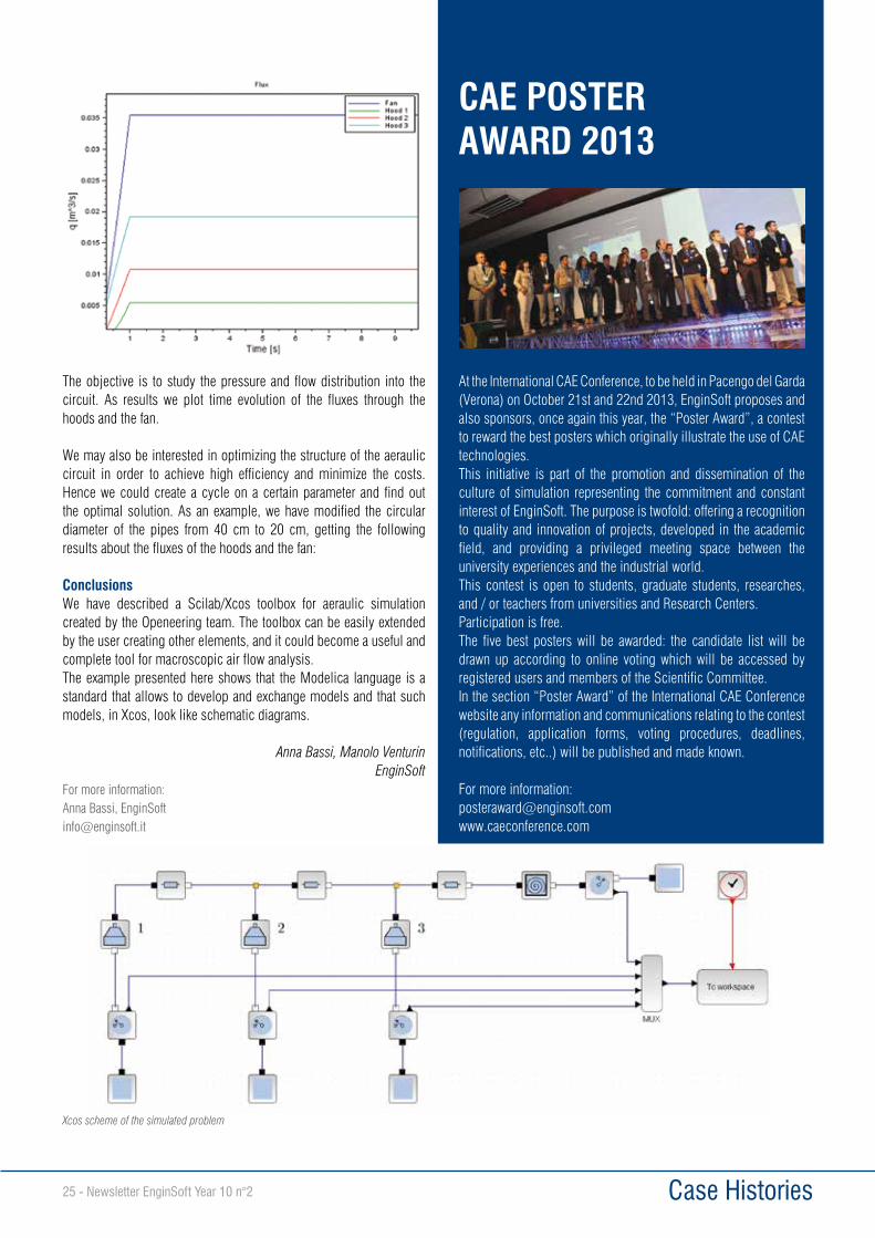
25 - Newsletter EnginSoft Year 10 n°2 Case Histories
The objective is to study the pressure and flow distribution into the circuit. As results we plot time evolution of the fluxes through the hoods and the fan.
We may also be interested in optimizing the structure of the aeraulic circuit in order to achieve high efficiency and minimize the costs. Hence we could create a cycle on a certain parameter and find out the optimal solution. As an example, we have modified the circular diameter of the pipes from 40 cm to 20 cm, getting the following results about the fluxes of the hoods and the fan:
ConclusionsWe have described a Scilab/Xcos toolbox for aeraulic simulation created by the Openeering team. The toolbox can be easily extended by the user creating other elements, and it could become a useful andcomplete tool for macroscopic air flow analysis.The example presented here shows that the Modelica language is a standard that allows to develop and exchange models and that such models, in Xcos, look like schematic diagrams.
Anna Bassi, Manolo Venturin EnginSoft
For more information:Anna Bassi, [email protected]
Xcos scheme of the simulated problem
At the International CAE Conference, to be held in Pacengo del Garda (Verona) on October 21st and 22nd 2013, EnginSoft proposes and also sponsors, once again this year, the “Poster Award”, a contest to reward the best posters which originally illustrate the use of CAE technologies.This initiative is part of the promotion and dissemination of the culture of simulation representing the commitment and constant interest of EnginSoft. The purpose is twofold: offering a recognition to quality and innovation of projects, developed in the academic field, and providing a privileged meeting space between the university experiences and the industrial world.This contest is open to students, graduate students, researches, and / or teachers from universities and Research Centers.Participation is free. The five best posters will be awarded: the candidate list will be drawn up according to online voting which will be accessed by registered users and members of the Scientific Committee.In the section “Poster Award” of the International CAE Conference website any information and communications relating to the contest (regulation, application forms, voting procedures, deadlines, notifications, etc..) will be published and made known.
For more information:[email protected]
CAE POSTER AWARD 2013
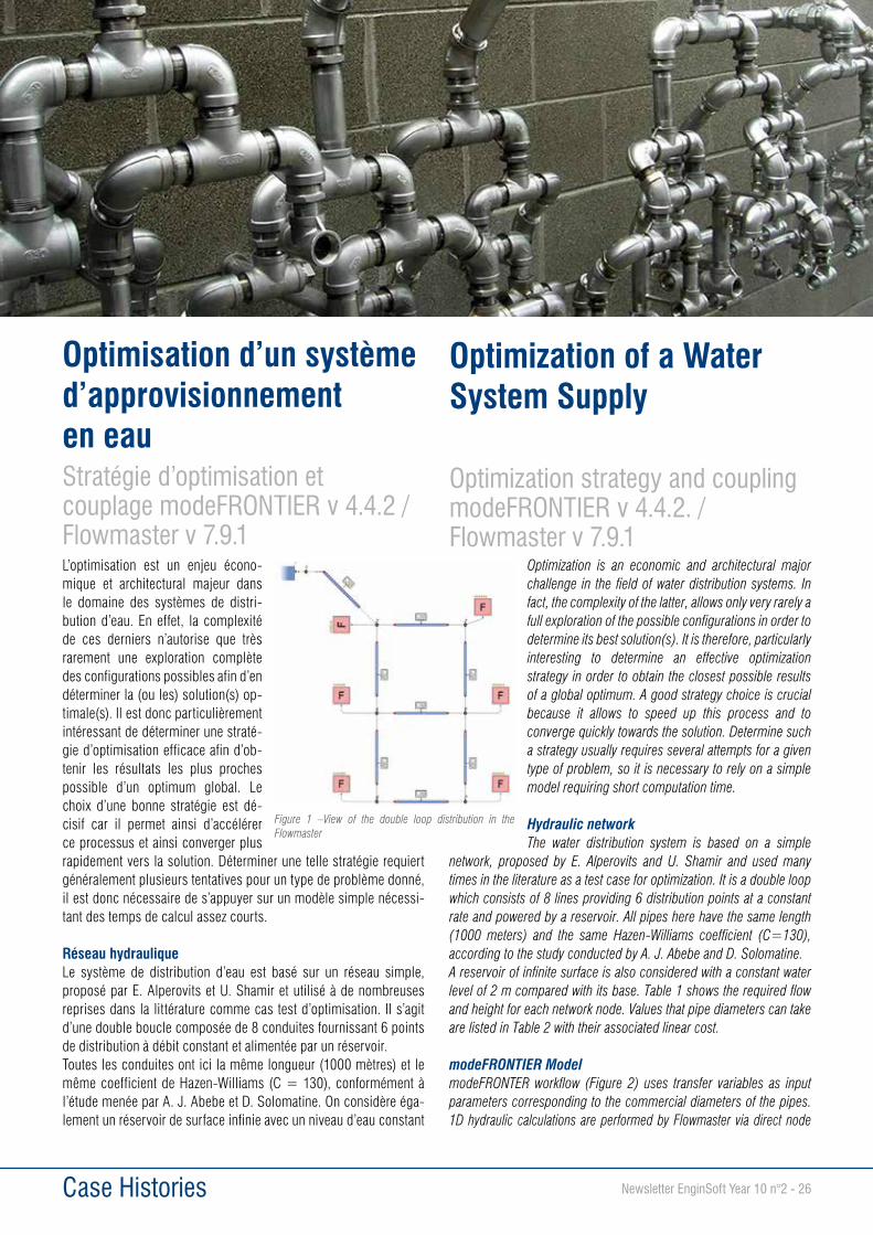
Newsletter EnginSoft Year 10 n°2 - 26
Optimization is an economic and architectural major challenge in the field of water distribution systems. In fact, the complexity of the latter, allows only very rarely a full exploration of the possible configurations in order to determine its best solution(s). It is therefore, particularly interesting to determine an effective optimization strategy in order to obtain the closest possible results of a global optimum. A good strategy choice is crucial because it allows to speed up this process and to converge quickly towards the solution. Determine such a strategy usually requires several attempts for a given type of problem, so it is necessary to rely on a simple model requiring short computation time.
Hydraulic networkThe water distribution system is based on a simple
network, proposed by E. Alperovits and U. Shamir and used many times in the literature as a test case for optimization. It is a double loop which consists of 8 lines providing 6 distribution points at a constant rate and powered by a reservoir. All pipes here have the same length (1000 meters) and the same Hazen-Williams coefficient (C=130), according to the study conducted by A. J. Abebe and D. Solomatine.A reservoir of infinite surface is also considered with a constant water level of 2 m compared with its base. Table 1 shows the required flow and height for each network node. Values that pipe diameters can take are listed in Table 2 with their associated linear cost.
modeFRONTIER ModelmodeFRONTER workflow (Figure 2) uses transfer variables as input parameters corresponding to the commercial diameters of the pipes. 1D hydraulic calculations are performed by Flowmaster via direct node
Case Histories
L’optimisation est un enjeu écono-mique et architectural majeur dans le domaine des systèmes de distri-bution d’eau. En effet, la complexité de ces derniers n’autorise que très rarement une exploration complète des configurations possibles afin d’en déterminer la (ou les) solution(s) op-timale(s). Il est donc particulièrement intéressant de déterminer une straté-gie d’optimisation efficace afin d’ob-tenir les résultats les plus proches possible d’un optimum global. Le choix d’une bonne stratégie est dé-cisif car il permet ainsi d’accélérer ce processus et ainsi converger plus rapidement vers la solution. Déterminer une telle stratégie requiert généralement plusieurs tentatives pour un type de problème donné, il est donc nécessaire de s’appuyer sur un modèle simple nécessi-tant des temps de calcul assez courts.
Réseau hydrauliqueLe système de distribution d’eau est basé sur un réseau simple, proposé par E. Alperovits et U. Shamir et utilisé à de nombreuses reprises dans la littérature comme cas test d’optimisation. Il s’agit d’une double boucle composée de 8 conduites fournissant 6 points de distribution à débit constant et alimentée par un réservoir. Toutes les conduites ont ici la même longueur (1000 mètres) et le même coefficient de Hazen-Williams (C = 130), conformément à l’étude menée par A. J. Abebe et D. Solomatine. On considère éga-lement un réservoir de surface infinie avec un niveau d’eau constant
Optimisation d’un système d’approvisionnement en eauStratégie d’optimisation et couplage modeFRONTIER v 4.4.2 / Flowmaster v 7.9.1
Figure 1 –View of the double loop distribution in the Flowmaster
Optimization of a Water System Supply
Optimization strategy and coupling modeFRONTIER v 4.4.2. /Flowmaster v 7.9.1

27 - Newsletter EnginSoft Year 10 n°2
implemented in modeFRONTIER. This allows to simplify the interaction between the two programs, especially by directly involving input and output modeFRONTIER variables with geometric and physical parameters of Flowmaster components (here, pipe diameters and static pressure at nodes) without using a batch file. Cost calculations are made via Excel Direct node on a sheet incorporating a macro. It is a mono-objective problem, which consists in minimizing the total network cost while respecting the constraints on the minimum static pressure required for branch connections, of 3 bar absolute.
Optimization methodThis model requires very short calculation times. However, the number of configuration to study (148, or about 1,4 billion combinations) does not consider a full exploration of the possibilities offered by this system and it demonstrates the value of applying an
efficient optimization scheme. The initial set of design (DOE) consists of 20 designs generated via the SOBOL algorithm. This allows to obtain points evenly distributed over the whole domain because of its pseudo-randomness nature. The use of SOBOL also permits to always generate the same design in the same order for the considered domain what allows to reproduce easily the DOE. The exploration phase is then carried out using the FAST-MOGA-II algorithm. The effectiveness of the MOGA genetic algorithm has already been observed in previous studies and justifies such a choice. This in fact, allows a global exploration of all possible configurations and has the advantage of finding a solution close to the global optimum due to the robustness of this type of algorithm. However, this type of exploration usually requires a large number of iterations (see Table 3, about 3000 iterations).
FAST methodTo speed up the optimization process, the choice of an algorithm both faster and with similar efficiency can be decisive. modeFRONTIER allows to use the so-called FAST methods related to algorithms such as the SIMPLEX, MOGA-II, NSGA2, MOSA…it is interesting to appreciate its effectiveness on an example already repeatedly proven.The principle of the FAST method is based on the training and use of adaptive response surface (RSM). These are created from the solutions of the DOE. The RSM giving the best performance is selected and used for virtual optimization via the specified algorithm (MOGA-II in our case). At each iteration, new designs are searched via an exploration
Case Histories
de 2 m par rapport à sa base. Le Tableau 1 donne les débits requis et la hauteur pour chaque nœud du réseau. Les valeurs que peuvent prendre les diamètres de conduites sont répertoriées dans le Tableau 2 avec leur coût linéique associé.
Modèle modeFRONTIERLe workflow modeFRONTIER (Fi-gure 2) utilise des variables de transfert comme paramètres d’en-trée correspondant aux diamètres commerciaux des conduites.Les calculs hydrauliques 1D sont réalisés par Flowmaster via le nœud direct implémenté dans modeFRONTIER. Ceci permet de simplifier l’interaction entre les deux logiciels, notamment en associant directement les variables d’entrée et de sortie de modeFRONTIER avec les paramètres géomé-triques et physiques des composants Flowmaster (ici, les diamètres et les pressions statiques en sorties de conduites) sans recourir à un fichier batch. Les calculs de coût sont quant à eux réalisés via le nœud direct Excel sur une feuille intégrant une macro. Il s’agit d’un problème mono-objectif, qui consiste à minimiser le coût total du réseau tout en respectant les contraintes sur la pression statique minimale requise au niveau des piquages, de 3 bar absolus.
Méthode d’optimisation Ce modèle nécessite des temps de calcul très courts. Cependant, le nombre de configuration à étudier (148, soit environ 1,4 milliard de combinaisons) ne permet pas d’envisager une exploration complète des possibilités offertes par ce système et démontre l’intérêt d’y ap-pliquer un schéma d’optimisation efficace.L’ensemble initial des designs (DOE) est constitué de 20 designs générés via l’algorithme SOBOL. Ce dernier permet d’obtenir des points répartis uniformément sur l’ensemble du domaine du fait de son caractère pseudo-aléatoire. L’utilisation du SOBOL assure également de toujours générer les mêmes designs dans le même ordre pour un domaine considéré ce qui permet de reproduire fa-cilement la DOE. L’exploration du domaine se fait ensuite à l’aide d’un algorithme de type FAST - MOGA-II. L’efficacité de l’algorithme génétique MOGA a déjà été observée lors d’études précédentes et
Figure 2 - Workflow for optimizing network costs respecting the constraints of pressures at the Flowmaster nodesTable 3 – Results published by Abebe and Solamatine
Table 2 – Cost of different commercial sizes
Table 1- Flow required in the double loop distribution and altitude of the different nodes

Newsletter EnginSoft Year 10 n°2 - 28
algorithm (SOBOL in our case) and then evaluated to enrich the training set in order to improve the predictability of the response surface. It is an iterative process ending when the convergence criterion is reached.
Results and ConclusionFigure 3 shows that the optimization process is greatly accelerated, and also gives a set of results much closer to the desired objective ($ 419, 000 , see Tab 3) compared to an optimization started with the MOGA-II algorithm (see Figure 4). The best design (ID 294) is obtained in the framework of this optimization with the FAST method for a cost of $ 420,000 (see Figure 3). Details of this configuration is given in Table 4 and in Figure 5. This method is particularly effective in this type of study because it can significantly reduce the computation time to find optimal solutions at least
equivalent to those of previous studies carried out. This also helps to further reduce the part of the domain to explore necessary to determine an optimal solution to the problem. Furthermore, the use of this type of method via modeFRONTIER provides the opportunity to determine a set of solution relatively close to the optimal solution which also makes the convergence process more interesting thanks to its less random profile.
This article is based on a previous work by A.Deponti and S.Poles (EnginSoft - Italy). The scope of the original work included the importance of a multiobjective approach. The whole approach will be covered, and presented, in a next issue.
More info :Xavier Trogneux – Université d’[email protected]
Romain Soulier, EnginSoft [email protected]@enginsoft.com
justifie un tel choix. Ceci permet en effet une exploration globale de l’ensemble des configurations possibles et présente l’avantage de rechercher une solution proche de l’optimum global liée au caractère robuste de ce type d’algorithme. Cependant, ce type d’exploration requiert généralement un grand nombre d’itérations (cf. Tableau 3, environ 3000 itérations).
Méthode FASTPour accélérer le processus d’opti-misation, le choix d’un algorithme à la fois plus rapide et à l’efficaci-té similaire peut s’avérer décisif. modeFRONTIER permet en effet l’utilisation de méthodes dites FAST liées à des algorithmes tels que le SIMPLEX, MOGA-II, NSGA2, MOSA ... il est donc intéressant d’en ap-précier l’efficacité sur un exemple déjà maintes fois éprouvé.Le principe de la méthode FAST repose sur la création et l’utilisation de surfaces de réponse adaptatives (RSM). Celles-ci sont créées sur la base des solutions de la DOE calculées au préalable. La RSM donnant les meilleures performances est choisie et utilisée pour l’optimisation virtuelle via l’algorithme spécifié (MOGA-II dans notre cas). A chaque itération, de nouveaux designs sont recherchés via un algorithme d’exploration (SOBOL dans notre cas) puis évalués afin d’enrichir la base d’apprentissage en vue d’améliorer la prédictibilité de la surface de réponse. Il s’agit d’un processus itératif prenant fin lorsque le critère de convergence est atteint.
Résultats et conclusionLa Figure 3 montre que le processus d’optimisation est fortement accéléré, et donne par ailleurs un ensemble de résultats beaucoup plus proches de l’objectif recherché (419 000 $, cf. Tableau 3) en comparaison avec une optimisation lancée avec l’algorithme MO-GA-II (cf. Figure 4). Le meilleur design (ID 294) est obtenu dans le cadre de cette optimisation avec la méthode FAST pour un coût de 420 000$ (cf. Figure 3). Le détail de cette configuration est donné dans le Tableau 4 et la Figure 5. Cette méthode est donc particu-lièrement efficace sur ce type d’étude puisqu’elle permet de diminuer de manière significative le temps de calcul pour trouver des solutions opti-males au moins équivalentes à celles d’études déjà menées. Cela permet également de diminuer en-core la part du domaine à explorer nécessaire pour déterminer une solution optimale au problème. Par ailleurs, l’utilisation de ce type de méthode via modeFRONTIER donne la possibilité de déterminer un ensemble de solution relativement proche de la solution optimale ce qui rend également le proces-sus de convergence plus intéressant du fait de son profil moins aléatoire.
Case Histories
Figure 3 - Cost in relation to design (FAST-MOGA-II)
Figure 4 - Cost in relation to design (MOGA-II)
Table 4 – Details of the optimal configuration obtained with FAST-MOGA-II
Figure 5 - Static pressure at the nodes of Flowmaster network

29 - Newsletter EnginSoft Year 10 n°2 Case Histories
The accurate analysis of the electromagnetic interference of complex systems is a fundamental requirement when two or more structures share the same working environment.This task cannot be carried out just by following analytical and empirical approaches. In fact, the analytical approach has the advantages of a rigorous method but known solutions are limited to few simple cases.On the other hand, empirical approaches commit to the operator experience all the mitigation actions and this could be not safe enough due to the complexity of the modern systems. The main drawback of the wide variety of empirical-numerical methodologies depends on the definition of simplified hypothesis on the electromagnetic material properties. Moreover an extensive experience is needed to define the applicability field of the involved mathematical relationships. In recent years, improvements in computational capabilities and availability of memory of the computing resources, have allowed us to efficiently solve problems that are characterized by several unknowns. In this work, we present a calculation approach for the study of the electromagnetic interference generated by high voltage lines and metallic pipelines. The calculation of the equivalent generators of the induced electromotive force has been performed by means of a Finite Element model. This approach
produces a generalization and an extension of the methods available in literature. In order to obtain fast and accurate results, the equivalent circuit has been analyzed by means of parametric software; ANSYS APDL and ANSYS Maxwell have been used to solve the finite element problem.
1. INTRODUCTIONFigure 1 shows an example of a scenario with a possible interference between a pipeline (yellow line) and some high voltage lines (3,4,7). The high voltage lines represent the inducing system (interference
Electromagnetic Interference between High Voltage Lines and Pipelines: an Advanced FEM Approach
Fig. 1. Geometry example of a high voltage line – pipeline system
Fig. 2. Geometry of the high voltage line – pipeline system
Fig. 3. 2D computational domain mesh (a) and particular of the pipeline (b)

Newsletter EnginSoft Year 10 n°2 - 30 Case Histories
source) and the pipeline is the induced system (interference target). The CEI 304-1 is the Italian regulation that sets the allowed limits for the voltages on a pipeline induced by a proximal high voltage system. CEI 304-1 does not specify how to perform calculations, although it suggests some references to be considered. Suggested calculations, historically represented the most popular solution and have been widely used for EMI (Electro Magnetic Interference) evaluation between high voltage lines and pipelines. In the most general case, the evaluation of inductive, conductive and capacitive coupling is required, where the inductive one is the most relevant.
The latter is due to the currents induced on the pipeline by a time-varying magnetic field, generated by a sinusoidal current flowing on the high voltage line. For the accurate evaluation of the induced coupling, a typical approach consists in estimating the currents induced on the pipeline–high voltage line system during both, the normal working conditions and in the case of a single phase breakdown case.
The conductive coupling occurs in the single phase breakdown case in proximity of the inductive installations provided on ground, such as electrical substations and electricity network trellis. Under this conditions the breakdown current flows into the soil increasing the electric potential in the local domain surrounding the pipeline. The evaluation of the generated voltage allows to establish the safety conditions for the operators, according to the limits imposed by the normative.The capacitive coupling occurs between both aerial high voltage and pipelines.The suggested method consists in modeling the pipeline as an equivalent electrical circuit, whose elements (generator, impedances, admittances) quantify some coupling effect. The circuital element values are analytically
calculated through approximated formulas that are based on classifications of the most popular standard geometrical configurations and on the most common architecture for high voltage lines and pipelines. This method is efficient when the interfering scenario can be assimilated to one of the suggested standards, but it lacks in precision for non-standard configurations. In such circumstances, a cautionary solution is usually found, in order to consider the worst cases. As an example, shielding effects due to metallic elements in the proximity of the high voltage systems are taken into account by simply reducing the value
of the induced ElectroMagnetic Force (EMF), without considering the actual geometry of these elements. Another non-standard configuration is represented by buried high voltage cables, because of their relatively short distance from the pipeline and because of the variety of electrical cables that can be used. Indeed, they are usually coaxial cables (and not simple wires as aerial lines) with more than one shield of several materials.
The proposed method, widely and successfully used by EnginSoft, is based on the numerical calculation of the circuital elements, instead of the analytical ones, of the equivalent circuit. This is done by generating accurate 2D and/or 3D models of the electrical and of the pipe system, including any significant component that could affect their physical interaction (other cables and pipes, shields, metallic grids).Hereafter, we show an example of the inductive and conductive calculation for some aerial high voltage cables and a buried pipeline.The electromagnetic analysis is performed according to the following steps:
1. Generation of the 2D FEM model to obtain the equivalent generators of the electromotive induced force.
2. Building and solution of the line transmission model by equivalent circuits.
3. Generation of the 3D FEM model to analyze the pipeline-high voltage line for the conductive disturbance.
3. 2D FEM MODEL FOR THE ANALYSIS OF THE INDUCTIVE COUPLINGIn order to evaluate the inductive coupling between the pipeline and the high voltage line, the two-dimensional model of a transverse section of the geometry, represented in Figure 1, has been taken into account. In particular, it is composed by (Figure 2-a):• the soil;• the air;• the inducting line;• the pipeline.
Fig. 4. Elementary cell of the equivalent circuit
Fig. 5. 3D model of the pipeline-transmission line system for the conductive problem
Fig. 6. Mesh of the computational domain (a) and of the dielectric cover (b)

31 - Newsletter EnginSoft Year 10 n°2 Case Histories
By observing the symmetry of the problem, the computational domain has been reduced to one half of the real one (Figure 2-c). The transmission line has been modeled by means of a current flowing orthogonally to the model plane, while the pipeline has been modeled by considering a metallic circular ring.
The computational domain has been properly discretized by means of a triangular element mesh (Figure 3-a) with quadratic shape function. Moreover, for an accurate evaluation of the skin effect on the pipeline, a finer mesh has been obtained of the external pipeline surface (Figure 3-b).
The flux lines of the magnetic field have been imposed parallel, in proximity of the boundary of the computational domain.
3. MATHEMATICAL MODELIn order to evaluate the current induced on the pipeline, the characteristic impedance of the system has been evaluated in ANSYS APDL (ANSYS Parametric Design Language).This procedure allows to obtain the equivalent circuit model of the pipeline as a series of elementary equally spaced cells. Each cell (Figure 4) is constituted by:
• An electromotive force that takes into account the effects of the induction system on the induced one;
• A longitudinal impedance that represents the pipeline impedance;• A trasversal impedance that accounts for the impedance between the
pipeline and the transmission line.
All these constitutive elements can be accurately calculated through 2D or 3D numerical analysis performed in ANSYS Maxwell.
4. 3D FEM MODEL FOR THE ANALYSIS OF THE CONDUCTIVE COUPLINGThe analysis of the conductive coupling has been carried out by using a three-dimensional model (Figure 5), where a part of 30 meters of pipeline buried into the soil, has been modeled by performing a parameterization ofboth geometric dimensions and the material properties according to the inductive case.The model is constituted by the soil, the metallic pipeline and an insulating layer placed around the pipeline itself.The three-dimensional domain has been
discretized by means of a tetrahedral element mesh with quadratic shape function (Figure 6-a). A finer mesh (Figure 6-b) has been obtained on the dielectric cover.
In order to define the boundary conditions, a zero potential has been imposed on the lower part of the calculation domain (Figure 7-a), while the excitation has been modeled as a current orthogonally directed respect to the surface soil (Figure 7-b).
5. RESULTSInductive and conductive interferences have been analyzed on a pipeline placed in proximity of three high voltage lines. The results relative to the inductive coupling obtained in normal working conditions have been shown in this article. By referring to the model shown in Figure 2-c, the inductive coupling has been evaluated; the induced voltage, calculated as function of the position along the pipeline and due to the three lines effect, has been shown in Figure 8.By referring to the previous figure, the voltage induced by each transmission line has been shown together with their quadratic mean square value.
6. CONCLUSIONSA FE-based procedure for the analysis of the electromagnetic interference, generated by a high voltage line and a pipeline, has been presented in this article.In order to completely describe the interference system, both the inductive and the conductive coupling have been taken into account. The two-dimensional and the three-dimensional FEM models have been generated and analyzed, with proper boundary conditions, by using ANSYS Maxwell. The equivalent generators of the electromotive force have been obtained from the FEM 2D model and given as input to the transmission line equivalent circuit. The 3D FEM model supplies the electric potential acting on the pipeline in case of a single phase fault.The aim of this study has been the generalization of the semi-analytic approaches for the electromagnetic interference problems: FEM models allow to obtain results even outside the validity domain of the Carson-Clem formulas.
Andrea Serra, Giovanni Falcitelli, Emiliano D’AlessandroEnginSoft
For more information: Andrea Serra, [email protected]
Fig. 7. Induced current (a) and zero voltage condition (b)
Fig. 8. Induced voltage along the pipeline

Newsletter EnginSoft Year 10 n°2 - 32 Case Histories
The complex challenge of meeting future environmental goals also in the general and sport aviation fields requires a multi-disciplinary approach that focuses on feasible propulsion systems, reduced fuel consumption, flight safety and reliability, noise reduction, and optimized aircraft design to achieve desirable flight characteristics.The latest research on the product innovation carried out by the most important aircraft manufacturers indicates that an effective choice in this direction is the adoption of the “more electric aircraft” design philosophy. As regards small aircraft, the reduction of the greenhouse gases emissions is possible even applying the battery electric propulsion. This last one is often labeled “green”, but actual emissions reductions should be compared with the environmental burden due to the production and decommissioning of the quite large power systems, typically based on NiCd or Lithium battery technologies.
Fuel cell systems are a key new technology for improving aircraft efficiency with more sustainability. Fuel cell systems can also provide, with almost null battery assistance, all of the main propulsion power for small airplanes. Small fuel cell-powered aircraft have succeeded in flying in recent years. These trends indicate that fuel cell systems in aircraft applications may help the evolution of the aviation industry.The present paper summarizes, step by step, the research activities worked out at the Politecnico di Torino to investigate the use of hydrogen in aircraft applications, and presents a solution conceived for the flying club to make the sport aviation more independent from the fossil fuel use. Moreover, the main achievements of this research, obtained since 2007, are presented.
FUEL CELLS FLIGHT TESTThe first activity was dedicated to the flight experiments of small fuel cells. In April 2007, a flight test campaign was carried out by a special test-bench installed onboard of an ultra-light aircraft. The core of this equipment was a 100 W air-cooled PEM hydrogen fuel cell supplied by compressed gaseous hydrogen. The aim of the test campaign was to measure the effect of the rarefied air on the performance of the fuel
cell electric generation. The air blower was not supercharged with the altitude. An automated input current profile was applied by an external load fed by the fuel cell system. The flight tests were performed at different flight levels to evaluate the simultaneous effects of altitude,
Hybrid UAV made in Turin The “Glider Project”
Figure 1. Results of the flight tests on a 100W fuel cell: polarization curves at different altitudes.
Figure 2. Results of the flight tests on a 100W fuel cell: power drop-off @ 4500 m.

33 - Newsletter EnginSoft Year 10 n°2 Case Histories
temperature and vibrations. The instrumented fuel cell stack output was connected to a controllable electric load with a programmable tablet PC. The input current profile was made of increasing step cycles (yellow curve, Figure 2) and repeated every 1000 meters of altitude. The results shown in Figures 1 and 2 indicate a generalized reduction in power generation with altitude, with the greater decrease at maximum power output of the 40% at 4500 m.
HYDROGEN APU FLIGHT TESTA further activity was the design, manufacturing and flight test of a hydrogen Auxiliary Power Unit (APU). Such device, installed on a general aviation plane, allows the power supply of the avionic system. The prototype is shown in Figure 3 and is based on a 1 kW liquid cooled PEM fuel cell, fed by gaseous hydrogen stored in a bottle at 200 bar. The equipment was integrated onboard of an ultra-light
aircraft (Figure 4), supplying electrical power to the avionic system and used also for the engine cranking.
A new test campaign was carried out in April 2008. A special cockpit interface was developed to allow the energy management and control during the flight by an LCD multifunction display, shown in the left part of Figure 5.
FIRST ITALIAN ELECTRIC FLIGHT: SKYSPARK PROJECTThe next two steps were to move towards the propulsion by electric energy from lithium battery and, finally, from a fuel cell system. The research program started with the design of a 60 kW fuel cell system for laboratory tests. It became necessary to prepare a test bench to qualify this propulsion system for flight. This is the stage where the test pilot
Maurizio Cheli proposed the idea to use, on the ULM aircraft class, the power generated by fuel cells for the electric propeller energized in a position to ensure the thrust needed for the flight. In this context was developed a feasibility study to assess the compatibility of the equipments with the capacity of an ULM aircraft class and the power required for a safe takeoff. The feasibility study gave a positive outcome. However, on the other hand, it highlighted the high cost of purchasing equipment and a special airplane for the role of technological platform At this point, the working group envisaged to set up a project with the formula of the “challenge”, acquiring the resources needed through sponsorship. The formation of a team to set objectives and timing became indispensable. The idea of the project was submitted to the rector of the Politecnico di Torino who welcomed it by proposing the establishment of an interdepartmental framework agreement, involving not only the Mechanics and Aerospace Engineering Department, but also the Department of Energy where a research group, already
Figure 3. CAD model and prototype of a 1 kW fuel cell APU.
Figure 4. Onboard integration of the APU.
Figure 5. Interactive multifunction display for the APU management during the flight tests.
Figure 6. The 65 kW electric motor.
Figure 7. The Pioneer 300 “Skyspark” aircraft.

Newsletter EnginSoft Year 10 n°2 - 34 Case Histories
involved in the development of electric vehicles, proposed to design an innovative electric motor (Figure 6), capable of supplying 65 kW of continuous power, with a specific power of over 2 kW/kg.After a careful evaluation of lightweight aircraft available on the market, the Pioneer 300 was identified as the best solution. Alpi Aviation, a
leader in the lightweight aircraft, was then contacted and asked to join the team. The company owner confirmed his decision to supply a special airplane (Figure 7).
The Skyspark project was divided into two phases: the first one was dedicated to the accomplishment of the first Italian electric manned flight, fixing a speed record, and the second one was addressed to the development of the fuel cell power unit to be able to substitute the batteries used for the speed record. The hydrogen system was designed and the components integration onboard of the Skyspark plane was studied (Figure 8) to solve weight and balancing, accessibility, and housing problems. In parallel, the laboratory tests of the fuel cell stacks began.As regards the propulsion plant, the electric motor and its inverter (Figure 9) were manufactured and tested in the laboratories of the Politecnico di Torino.
A special Lithium-polymer battery was built, tested and integrated onboard of the plane together with all the electric components (Figure 10) to allow the maiden flight, before the ground test on the hydrogen system were completed.In the occasion of the World Air Games 2009, held in Turin, the Italian astronaut Maurizio Cheli flew with the Skyspark for the first time on June 8th, then on June 10th was airborne for 8 minutes and hit a top speed of 155 mph (250 km/h) with an electric battery propulsion. The record track, registered by a GPS receiver, is shown in Figure 11.
As Boeing flew in Ocana (Spain) only few months before the Skyspark with a Super Dimona powered by PEM fuel cells, it was decided to freeze the Skyspark project, stopping the integration of the hydrogen system, even if it was already tested in ground laboratories. The research group of the Politecnico di Torino decided to move towards new and more promising flying concepts.
DEVELOPMENT OF A GLIDER DEMONSTRATOR MODELThe experience gained with the Skyspark project led to a new aircraft configuration more suited for the hydrogen technology application. The new architecture considers a motor-glider as reference as it allows a strong reduction in the maximum installed power rating and in the cruise power level, with a considerable reduction in energy storage and thermal management problems of the power plant.In the summer of 2009 the decision to develop a scale demonstrator of this new architecture was taken. The H2plus demonstrator, the
Figure 8. The hydrogen system integration on-board of the “Skyspark” aircraft.
Figure 9. Electric motor and inverter manufacturing and testing.
Figure 10. System integration on the Skyspark plane.
Figure 11. The ground track of the Skyspark plane of the record flight of June 10th, 2009.
Figure 12. The ASK21 modified glider model

35 - Newsletter EnginSoft Year 10 n°2 Case Histories
first Italian electric UAV with compressed hydrogen propulsion, was launched. This model is conceived as a flying test bench on which it is possible to develop the entire project, validate the fuel cell system solutions and the analysis methodologies used for the design optimization. This flying platform is a scaled reproduction of a trainer-acrobatic glider, the Schleicher ASK21. The model has a wing span of 4.2 m (Figure 12). The fuselage was modified with the integration of the electric motor on a dedicated fixed mast to allow the integration of the propulsion.
The power plant uses an energy mix made by three electric sources: fuel cell, lithium battery and photovoltaic. The main energy supply comes from a 300 W (net) air cooled PEM fuel cell (Figure 13), integrated by a small 25Ah Li-Po battery; moreover, a poly-crystalline thin film solar cover, laminated on the upper surfaces of the wing and
horizontal tail, supply up to 100 W, when in optimal sun exposition. A couple of air intakes were created on the transparent canopy for air feeding and cooling of the fuel cell.
Keeping in mind the final real application, the proposed solution makes the aircraft autonomous for each flying phase (take-off without towing) and during mission operations. The reference mission is made of the following typical phases: take-off, climbing and flight to reach the operative zone, straight and level flight, return phase and landing. The energy mix was chosen to sustain the horizontal flight without draining energy from the battery.
The flight tests demonstrated some instability during the take-off and a dangerous nose-down tendency after the rotation maneuver. To correct these lacks a new model was chosen, the ASW15 and the
electric motor with a retractable propeller was installed just on the top of the fuselage bow. This model is bigger than the ASK21 (more than 5 m of wing span). This also allows a higher payload. To avoid the ground contact of the blades of the propeller during the take-off, the solution of the dolly was preferred to the installation of a landing gear.
DATA ACQUISITION AND TELEMETRY The ASW15 platform is equipped with a data acquisition and telemetry system that allows all the relevant sensors information to be acquired and transmitted to a dedicated ground station. The system could be divided into two main parts. The first is common for all the test campaigns, its task is to acquire the flight parameters, such as attitude, position and speed, and send all data to the ground station (Figure 15). Its main components are: • an Inertial Measurement Unit, provided with a three-axis
accelerometer, a two-axis gyroscope and a 1-axis gyroscope. • a GPS receiver • a board with a microcontroller handling all the operations • a wireless modem
Figure 13. The 300 W PEM fuel cell integrated on ASK21 model
Figure 14. The ASW15 modified glider model.
Figure 15. The flight data acquisition and telemetry system schematics.
Figure 16. Payload data acquisition schematics.
Figure 17. The ground station graphic interface.

Newsletter EnginSoft Year 10 n°2 - 36 Case Histories
The second part of the system is dedicated to the acquisition of data regarding the subsystem under test and therefore it will be specifically designed for each test campaign (Figure 16). As a general rule, it is composed of: • the necessary sensors for a complete analysis of the problem
under investigation • a signal conditioning unit • a microcontroller for signal acquisition and communication with
the main telemetry system
The ground station consists of a wireless modem receiver connected to a laptop pc running a dedicated software (Figure 17). Two windows are selectable: the first showing a virtual cockpit with flight data, the latter showing data concerning the subsystem under test. All data are saved in a file for subsequent analysis. The aircraft is also equipped with an onboard video camera connected to a 5.8GHz transmitter. The ground station receives and records the video (Figure 18).
GREEN GLIDER PROJECTAs anticipated before, the scope of the project is the development of a manned ultra-light motor-glider with electric propulsion, moving from the expertise gained from the Skyspark and H2plus projects and related flight tests. There are several potential advantages in this proposal:• The aircraft architecture is very valuable by the ultra-light flight
enthusiasts, and very attractive for flying schools and gliding clubs thanks to the two seats architecture: in fact, the motor-glider benefits of the total operating independence without the hassle of aero-tows or winch launches. Moreover, keeping in mind its innovative hydrogen technology, the aircraft would be a charming attractive point for a flying school.
• It is also possible to develop a special version of the motor-glider with the integration of a photovoltaic generation system on the wing, as already experienced with the ASK21 model, that allow a subsidiary power generation to double the flight endurance during the sunny days.
• Compared with the lithium battery technology the compressed gas hydrogen fuel cells allow the quick energy recharge (few minutes vs. several hours), and above all a general increase of the flight endurance with the same payload.
The following consolidated key-facts related to the project are noteworthy and suggest the feasibility of the idea:
• The consolidated collaboration with HysyLab laboratories of Environment Park Torino for the ground testing of the hydrogen power line;
• Patronage of the Torino Chamber of Commerce and Regione Piemonte;
• First project with this challenging characteristics at a World level;• PureWings project spin-off, a joint Milan and Turin Polytechnic
(Alta Scuola Politecnica) study to develop special hydrogen technologies [6];
• Strong participation of SMEs in the development of special components and technologies with possible spin-offs in other engineering applications, not limited at the aerospace field;
• In contact with a wide network of flying schools and glide clubs, potential customers and users of the Green Glider aircraft.
The most ambitious idea is the proposal of a totally new aircraft, based on the sketch of the designer Bruno Giardino (Figure 19), based on Flyvolt G 208 concept (Bureau of European Design Associations - Bronze A’ Design Award, winner for aerospace and aircraft design category, in 2011). The power plant configuration, having three electric motors, allows a more efficient generation of the trust with a different activation of the
motors between take-off and cruise phases.Different are the technical keynote points:• The proposed type for the electrical propulsive motor is the well
known brushless direct current (BLDC) technology, typically with low life cycle cost, low weight, long endurance and high reliability characteristics.
• The replacement of the large and expensive lithium battery with a PEM fuel cell system is proposed, plus an optional wing coverage of flexible poly-crystalline solar photovoltaic.
• A continuous power rating at the maximum flight efficiency aircraft attitude of about 5kW is expected.
• The electric power supply system should be able to provide 20kW @110-70V by a fuel cell, with a very small battery for the start-up of the fuel cell system (<2kWh).
• Maximum 2kW from solar photovoltaic, in flexible poly-crystalline silicon, to increase the endurance, looking at the Erik Raymond’s Sunseeker prototypes.
Figure 18. Video streaming from the on-board camera.
Figure 19. Designer impression for the Green Glider aircraft.

37 - Newsletter EnginSoft Year 10 n°2 Case Histories
• A dedicated recharging station to produce the necessary hydrogen by water electrolysis.
The proposed solution is capable of maintaining the same payload of the lithium battery reference aircraft, but with a double flight endurance and a better life cycle cost (quick decay of the lithium battery performances with number of discharge cycles).Moreover, the proposed power rating for the fuel cell system (20kW), together with the compactness and lightness, necessary for the motor-glider application, could be easily adapted to a wide range of ground mobility applications, keeping in mind that the best advantage for a non flying system is even so the independence from the battery operating cycle that implies long recharging time, short operating life, and onerousness of battery disposal and recycling. A more feasible solution foresee the use of an existing glider: the Silent 2 Electro (Figure 20), from the Alisport, that has been selected also
for its similarity with the H2plus ASW15 configuration. This glider with its nose-mounted electric propulsion system designed specifically for the Silent is the most modern and environmentally compatible solution. The electric motor installed in the nose of the glider with folding propeller blades is aerodynamically clean. It is foreseen the substitution of the traditional lithium battery, located back to the pilot seat, with a compressed hydrogen PEM fuel cell.
Due to the high aerodynamic efficiency (Figure 21) and lightweight this solution allows the reduction of the cruise power rating to 4 kW and the battery capacity to support the take-off phase.
Prof. Paolo MaggiorePolitecnico di Torino
Figure 20. The Alisport Silent 2 Electro glider.
In November 2012, SWS Engineering S.p.A won the “Technical Innovation of the Year Award” at the 2012 NCE International Tunnelling Awards held in Toronto, Canada. The aim of the awarded project was to investigate how expanded clay can be successfully employed as back-filler in deep mechanized tunnelling, in particular when convergence problems occur. An extensive laboratory characterization of the material, combined with numerical simulation and on-site testing, proved that expanded clay, loose or mixed with cement, can be easily injected, and that it provides the required confinement right after placement of the segmented lining. The studies also revealed that expanded clay is capable of transferring large volumetric strains and reduced stresses to the tunnel lining. Expanded clay is an optimal solution to prevent tunnel lining collapse when the rock mass characteristics may lead to large midterm or long-term convergence. The project conducted by SWS Engineering with the support of Laterlite Spa and the Politecnico di Milano, won against a number of high class initiatives presented by such well-known international companies as Halcrow, Strabag and Mott MacDonald.
SWS Engineering and EnginSoft are daughter companies of the SWS Group. SWS Engineering is also EnginSoft’s partner for projects in Italy and around the world that require in-depth geotechnical engineering analyses, knowledge and experiences.SWS Engineering has an impressive and long track record in the investigation, design and treatment of tunnels and underground workings. Recent international Projects include the Tunnel du Pertus between Spain and France, the Danes Tunnel in Romania, the Adapazarı Northern Pass of Turkish State Railways, the Tramway Algeria with 11 stations and 2 viaducts, and the Metro in Singapore. To read more about SWS’s competencies in geotechnical engineering, tunneling and for structures, please visit: http://www.sws.it
SWS wins the “technical innovation of the year” at the International Tunnelling Awards
The Awards Ceremony on 29th November 2012 at the Sheraton Centre Toronto Hotel

Newsletter EnginSoft Year 10 n°2 - 38 Interviews
1. Dottor Faggin, lei è ritenuto da tutti il padre del micro-processore. Ci racconta cosa accadde, nei lontani anni ’70, all’Intel?Il microprocessore è nato nel 1971, all’Intel, attraverso una serie di fattori fortunati. L’opportunità scatenante fu una richiesta da parte di cliente giapponese, la Busicom, di sviluppare speciali circuiti integrati destinati ad un nuovo prodotto: una calcolatrice da tavolo. In specifi-co la richiesta riguardava un CPU (Central Process Unit) che il cliente riteneva si dovesse produrre con 3 chip. La necessità di Busicom evidenzia l’allora richiesta di calcolatori che, per essere considerati potenti e flessibili dal mercato, dovevano essere programmabili. In pratica l’attuale concetto di Computer. Il concetto, in realtà, nacque in Italia a partire dalla metà degli anni ’60 (1965 per l’esattezza) con la “Programma 101” di Olivetti: di fatto il capostipite dei computer programmabili da tavolo. Con la “101” si dimostrò che, attraverso l’impiego di un piccolo com-puter, si potevano creare dispositivi da tavolo, da “desk”, capaci di risolvere una vasta gamma di problemi. Colossi come la HP nel ‘68 e la Busicom nel ‘69, intu-irono l’enorme potenziale di mercato e si rivolsero all’allora pressoché sconosciuta Intel al fine di creare una famiglia di cal-colatori programmabili. A quei tempi solo Intel e Fairchild detenevano conoscenze e tecnologia per, potenzialmente, raggiun-gere l’obiettivo: la Silicon Gate Technolo-gy. Tecnologia da me sviluppata nel 1968 in Fairchild Semiconductor. Anche i miei ex-colleghi di Fairchild, e che fondarono la Intel, ne erano in qualche modo a co-noscenza. All’Intel Ted Hoff, capo delle applicazioni, analizzò le necessità e le specifiche di progetto Busicom e si stupì
della complessità del circuito logico del CPU. In realtà questi risul-tava complesso perché il concetto circuitale prevedeva l’impiego di Memoria Seriale: considerate ai tempi le uniche memorie riscrivi-bili. Per inciso, gran parte dei piccoli sistemi che necessitavano di memoria riscrivibile (R/W) impiegavano componenti “shift register” – ovvero memorie seriali. Anche la “Programma 101” impiegava Se-rial Memory ed era prodotta impiegando fili magnetostrittivi. Stessa memoria anche per i primi computer grandi quanto un soggiorno! Questo tipo di Memoria divenne obsoleta, a partire dalla metà-fine degli anni ’50, con l’avvento delle memorie “Random Access Me-mory” – o RAM - che sono molto più veloci e consento di creare computer più semplici e potenti perché ogni cella è velocemente e direttamente accessibile.
Dal primo Microprocessore al Computer QuanticoFederico Faggin – un’eccellenza italiana al servizio del progresso
Federico Faggin nella sua abitazione nella Silicon Valley

39 - Newsletter EnginSoft Year 10 n°2 Interviews
L’Intel venne fondata per produrre memorie semiconduttori e, a quel tempo, impegnata nello sviluppo di memorie dinamiche RAM. Fu quindi naturale per i progettisti analizzare alternative all’impiego di Memoria Seriale, formata da 6 transistori per cella, verso una più performante e semplice Memoria Dinamica, che ne impiega solo tre. Il circuito concettuale risultante costituiva quindi un CPU più semplice, veloce e meno costoso. In pratica si ottenne un’ulterio-re semplificazione dell’allora architettura di computer verso un si-stema più semplice e idealmente contenuto in un solo chip. A quel punto tutto si arenò perché nessuno all’Intel possedeva conoscenze adeguate per sviluppare questo nuovo progetto che necessitava di una nuova metodologia di sviluppo. Know-how allora non disponi-bile in Intel che prevedeva l’impiego della tecnologia Silicon Gate Technology da me sviluppata in Fairchild. A quel punto venni assunto e mi affidarono l’intero progetto in quanto esperto di architettura di computer, di progetti: logico, circuitale, per circuiti integrati e infine di processo. Con questo bagaglio di competenze integrate, in circa 11 mesi, il team da me guidato riusci a sviluppare non solo la CPU, in un unico chip, ma anche la memoria RAM, la ROM e il circuito di input-output (I/O). Praticamente una famiglia di elementi con i quali si potevano creare computer diversi per dimensioni e potenza di calcolo. In conclusione. A quel tempo tutti erano a conoscenza di come ar-chitettare un piccolo computer, molti sapevano come fare il progetto logico, ma nessuno il progetto circuitale. La metodologia di progetto da me sviluppata, che prevede l’impiego Intelligente della Silicon Gate Technology, cambiò radicalmente lo scenario tecnologico di allora e consentì di produrre il primo microprocessore al mondo. Il chip più importante, famoso e longevo da me sviluppato in Intel è stato l’8080 che è stato il primo processore veloce ad 8 bit.
2. L’umanità ha beneficiato di importanti scoperte che han-no cambiato il corso della storia. Il fuoco, la ruota, e via via nei secoli sino alla più o meno recente trasformazione della Società da agricola ad industriale attraverso il motore. Il suo contributo, con l’invenzione del primo microprocessore, ha consentito all’Information Technology in generale, di estende-re la capacità intellettuale degli individui facendo fare all’at-tuale Società, di fatto, un salto tecnologico: da industriale ad informatica. Per questo enorme contributo “sociale” come si sente?Ovviamente sono onorato di aver contributo alla trasformazione. L’essenza del microprocessore, essendo formato da un solo chip nel quale sono integrate memoria ed I/O come è avvenuto nei succes-sivi sviluppi, ha consentito di miniaturizzare e produrre il computer attraverso un unico chip. L’innovazione consentì di ridurne drasti-camente le dimensioni, il peso, la potenza elettrica necessaria ad alimentarlo quindi il calore da dissipare. Ma soprattutto aumentarono a dismisura, via via attraverso i diversi stadi evolutivi, le prestazioni che consentirono di applicare il concetto di computer ai più dispa-rati impieghi. La potenza di calcolo degli anni ‘60-70, sviluppata da un computer grande come un TIR, è oggi disponibile all’interno di un moderno spazzolino da denti. Quindi il fatto di miniaturizzare il computer all’interno di un pezzettino di silicio stravolse completa-mente lo scenario applicativo portando la tecnologia del computer ad essere applicata a qualsiasi prodotto. Oggigiorno l’impiego del
Il talento dei microprocessoriFederico Faggin, classe 1941, è considerato dalla comunità scientifica internazionale tra le più brillanti menti del ‘900.Terminati gli studi universitari a Padova, e dopo essersi distinto in SGS-Fairchild (oggi ST Microelectronics) con importanti e geniali lavori sui semiconduttori, accetta un’esperienza di lavoro presso la consociata americana Fairchild a Palo Alto in California-USA. Nella “caldera” della Silicon Valley la genialità di Faggin fa fare balzi da giganti ai processi di produzione dei semiconduttori. In pochi mesi, infatti, questi sviluppa il processo MOS - Silicon Gate Technology: tecnologia alla base delle moderne memorie e dei microprocessori. Oggi più del 90% di tutti i circuiti integrati prodotti nel mondo impiega questa tecnologia. Nel 1970 si trasferisce all’INTEL dove organizza i processi di R&D e produce il primo microprocessore al mondo (INTEL 4004), contribuendo al successo tecnologico dell’azienda di Santa Clara. Nel 1974 fonda ZiLOG, prima azienda americana espressamente dedicata allo sviluppo e produzione di
microprocessori. Nasce qui lo Z80 che negli anni ’70 spopolò, quale processore a 8bit, e venne impiegato nei primi videogiochi ed home computer (Amiga, Sinclair, ecc.). Lo Z80 è considerato tra i più longevi chip mai sviluppati e pietra miliare per i moderni computer. Faggin contribuì, successivamente, allo sviluppo delle tecnologie alla base della trasmissione “voce-dati” e dei Touchpad/Touchscreen. Dal 2004 al 2008 diviene CEO della Foveon, azienda american satellite della Giapponese Sigma, e sviluppa retine artificiali destinate all’impiego su fotocamere digitali. Nel corso della sua lunga attività imprenditoriale ha ottenuto venticinque brevetti, cinque lauree honoris causa e una ventina di prestigiosi riconoscimenti. Federico Faggin nel corso della sua vita ha saputo ripetutamente andare oltre la conquista – pur straordinaria – del momento, per affrontare nuove sfide che significavano invariabilmente passare ad un’altra azienda o fondarne una nuova, trovare nuovi collaboratori o giovani talenti da supportare, impegnarsi in contesti tecnologici e scientifici fino ad allora anche per lui pressoché sconosciuti. Anche Barack Obama, in qualità di Presidente degli Stati Uniti d’America, ha riconosciuto l’operato di Federico Faggin negli anni conferendogli, nel 2010, la National medal of technology and innovation quale premio per l’innovazione scientifica e per aver contribuito a trasformare la Società da industriale ad informatica facendo fare un balzo in avanti al benessere dell’umanità.

Newsletter EnginSoft Year 10 n°2 - 40 Interviews
microprocessore, o microcontrollore, è vastissimo. Nelle nostre case sono presenti parecchie centinaia di microprocessori che governano le funzioni dei più disparati dispositivi: e il proprietario quasi quasi non sa di possederli… Questi, in forma “embedded” ovvero integrati con il prodotto, non sono normalmente visibili. Ad esempio la mia macchina per il caffè espresso, che è una macchina automatica, ha almeno un microprocessore all’interno. Nessuno ci pensa ma schiac-ciano un bottone questi, in un ciclo logico programmato, si adopera per produrre un buon caffè italiano anche qui in California.
3. Ritiene che l’ambiente e le opportunità offerte dalla Sliicon Valley abbiano favorito la sua invenzione?Senz’altro! L’ambiente è altrettanto importante quanto le persone. Se io fossi rimasto in Italia, penso, che non avrei mai avuto l’opportunità di inventare il microprocessore. Anche lavorando per un’azienda di semiconduttori all’avanguardia come la ST-Micro, o come si chia-mava allora, SGS-Fairchild. La ragione è molto semplice. Nemmeno l’Intel avrebbe avuto l’idea se non fosse stato per un bisogno da sod-disfare. Attraverso questa iterazione, una combinazione fortunata di fattori, è nata l’idea del microprocessore. Ma le opportunità di questa natura possono nascere solo in un paese che è all’avanguardia in uno o più settori. I clienti più “Avventurosi” e geniali si rivolgono ovviamente agli innovatori presenti nei paesi all’avanguardia. Questi, di fatto, finanziano e mantengono all’avanguardia quel paese. È un circolo virtuoso che deve essere costantemente alimentato e favorito.
4. Il Microprocessore non fu la sua sola scoperta. Ovvero la riprova della sua genialità ci fu anche l’intuizione e lo sviluppo del Touchpad. Un dispositivo che ha migliorato radicalmente l’interfaccia uomo-macchina ma che negli anni ’80 non susci-tò interesse tra le grandi dell’IT: tranne che per Apple. Steve Jobs fu veramente visionario o ebbe un enorme colpo di fortu-na nel credere alla sua invenzione?Il touchpad in Apple, in realtà, fu adottato prima che Steve Jobs tor-nasse alla guida della società nel 1997. Jobs fu, invece, il primo a credere e ad impiegare industrialmente il Touchscreen. Cioè la stessa idea del Touchpad però applicata, attraverso un sensore trasparente,
resistivo o capacitivo, ad un display a cristalli liquidi. Il sistema venne sviluppato da noi in Synaptics che fondai nel 1986. Il dispositivo nac-que durante il tentativo di migliorare i limiti del “track ball”: il punta-tore usato prima del Touchpad. Questi, oltre ad essere un dispositivo molto ingombrante, necessitava di frequente manutenzione mecca-nica perché altrimenti soggetta a malfunzionamenti. Il prototipo ven-ne presentato alle principali aziende IT, di fine anni ’90, senza trovare consenso e disponibilità ad assumersi il rischio nell’adottare questa innovazione. L’Apple, e a quel tempo c’era Steve Jobs, fu l’unica ad
intuire l’importanza strategica del Touchscreen. L’azienda accettò di impiegare il nostro Touchscreen a patto che con-cedessimo loro l’esclusiva. Non trovammo un accordo ra-gionevole e Apple decise, quindi, di svilupparselo da sé. La storia, in realtà, un po’ più complicata di questa sintesi così come spesso lo sono le storie vere. Ciò che rimane è che il Touchpad e il Touchscreen sono invenzioni che noi svilup-pammo alla Synaptics in maniera completamente indipen-dente. Synaptics è tutt’ora una delle realtà più importanti e all’avanguardia nello sviluppo e produzione di Touchpad e Touchscreen per notebook, telefoni, tablet, ecc.
5. Ci illustra i principi alla base dei Computer Quanti-ci e quali sono le aspettative in termini di progresso con il loro futuribile avvento? Il Computer Quantico, a differenza del computer tradiziona-le, che utilizza la logica booleana, impiega la logica della meccanica quantistica che ammette l’esistenza di stati in sovrapposizione. Per esempio, lo stato in sovrapposizione
più semplice, è il Quantum Bit o Qbit che ha facoltà di esistere sia in stato “1” che “0”; nella logica booleana, alla base dell’attuale in-formatica digitale, lo stato del bit può essere “1” oppure “0”. Nel caso della logica quantistica il Qbit può esistere sia a stato “1” che “0”. Non perché non si conosce se lo stato è “1” o “0”. Può esserlo entrambi in modo logico! E questo è un paradigma che viola, in appa-renza, la legge Aristotelica del “Medio escluso”. Quindi è una logica che non può esistere nella normale realtà, tridimensionale, alla quale siamo abituali ma richiede una evoluzione culturale e l’adozione di principi matematici diversi dal tradizionale. Nel futuribile computer quantico, attraverso il quale le operazioni sono eseguite con stati in sovrapposizione, sarà possibile eseguire 2100 operazioni simulta-nee. Ciò è impossibile da eseguire con la struttura di computer at-tuale. Per cui la promessa del Computer Quantico è di poter eseguire, esponenzialmente, molte più operazioni di un computer classico.
Questi potrebbe, ad esempio essere impiegato per elaborare dati con crescita esponenziale. Ciò che richiederebbe, potenzialmente, molti anni di elaborazione sul più potente computer “normale” oggi dispo-nibile, sarebbe disponibile attraverso un quantico in qualche ora. In sintesi il computer quantico consentirà di risolvere problematiche ad oggi considerate in pratica irrisolvibili da un computer dalla struttura classica: non importa quanto veloce esso sia. Molti Centri di Ricerca, ma anche aziende commerciali, stanno da tempo investendo risorse sul tema. Tuttavia è mia opinione che trascorreranno dai 15 ai 30 anni prima dell’avvento di un prodotto commerciale. Il Computer Quantico è per il momento ancora un progetto: in parte concettuale e in parte sperimentale.
Ted Hoff, Federico Faggin e Stanley Mazor; il team che in Intel sviluppò il primo microprocessore, premiati con la “National Medal of Technology and Innovation” da Barak Obama nel 2010.

41 - Newsletter EnginSoft Year 10 n°2 Interviews
6. La sua passione ed interesse per la neuroscienza, e in par-ticolare i suoi studi sulla Consapevolezza, sono stati da lei più volte pubblicamente citati. Ci può rivelare quale altra invenzio-ne ha in serbo? Un Computer Consapevole?Beh, anche qui devo precisare. Il mio interesse per capire la natura della Consapevolezza mi ha portato a creare una Fondazione per lo studio appunto della Consapevolezza, di cui naturalmente sono Pre-sidente. Non ho mai affermato di voler creare il “Computer Consa-pevole”. Anzi! Ho detto l’esatto contrario. Ovvero che è impossibile realizzare un computer consapevole in quanto la Consapevolezza è una proprietà che, a mio parere, non è il risultato di un processo lo-gico booleano. Quindi come minimo occorre un computer quantico per riuscire a creare una macchina consapevole. Ma non ne sono certo anche con l’impiego di un Quantico. Sicuramente non è pos-sibile farlo con un sistema deterministico come lo è un computer classico. Quindi il computer tradizionale consapevole è assolutamente fuori da ogni possibilità. Più che sulle invenzioni, voglio capire il principio fisico che consente all’uomo, o ad un animale, di essere consapevole. Lo considero un mistero fondamentale, una domanda, alla quale nessuno ad oggi ha ancora dato risposta.
7. Il sistema-impresa Italia è in evi-dente difficoltà e, contrariamente agli altri paesi industrializzati dell’area Euro, stenta a riprendersi dalla crisi economica. Ritiene che il problema sia dovuto a Politiche inadeguate oppure al fatto che la Creatività che contraddistingue noi italiani si stia assopendo?È mia opinione che le difficoltà scaturi-scano da politiche generali, e puntuali, non corrette o non più attuali. L’Italia sof-fre soprattutto della mancanza di infra-
strutture adeguate più che di creatività. Sono convinto che quest’ul-tima, negli italiani, c’è sempre stata e continuerà ad esserci così come quella espressa anche da altri paesi e da altri popoli. Per cui non è certamente la mancanza di creatività, o voglia di “fare”, il pro-blema principale. Questi, a parer mio, è soprattutto localizzato nella necessità di strutturare un sistema-paese che consenta di ottenere vantaggi dall’espressione di creatività se questa si accompagna ad altri aspetti fondamentali. Come la voglia di lavorare, di innovare, il coraggio di assumersi dei rischi, e così via. Elementi necessari e fondamentali alla creazione di nuove idee.
8. Lei che è stato, ed è tuttora, un imprenditore di successo ha una ricetta da suggerire ai colleghi italiani per uscire dall’at-tuale empasse?Mi dispiace ma non possiedo nessuna ricetta pre-costituita. Credo che non esista una formula magica per uscire dall’empasse. È come quando le automobili arrivano ad un incrocio e trovano un ingorgo e nessuno riesce più a muoversi. Allora, facendo molta attenzione, si deve trovare il modo di muovere la prima auto, quindi la successiva e così via sino a liberare l’ingorgo e far riprendere la circolazione in modo fluido. La metafora, qui in America denominata “Grid lock”, illustra l’attuale condizione in cui si trova l’Italia. È una situazione molto difficile per cui non esiste una formula facile da applicare per sbloccare il tutto, per uscire dallo stallo. Si tratta di cambiare le tante “cose” che non funzionano. Occorre grande forza di volontà e pazien-za. Quindi un problema grandissimo che solo con estrema attenzio-ne, perseveranza e forza di volontà si potrà risolvere.
9. E ai giovani che si affacciano al mondo del lavoro? Suggeri-sce loro di rimanere in Italia o di emigrare verso paesi, come
gli USA, che offrono più opportunità di esprimersi?Consiglio sempre ai giovani di seguire la propria inclinazione ovvero di “fare” ciò che uno ama “fare”. Di seguire i propri “sogni”, le proprie inclinazioni. Se que-sto è possibile farlo in Italia benissimo! È lì che si dovrebbero cercare e trovare le soluzioni alla propria carierà. Tuttavia se questo non fosse possibile in Italia, suggerisco di trasferirsi laddove ci sono i presupposti e l’ambiente per raggiungere i propri obiettivi ed aspettative. Non po-ter fare ciò che uno ama fare, non poterlo far bene, o non poter dare il massimo, è un perdita non solo per il popolo italiano ma per tutta l’umanità. Quella creatività, possibile creatività, possibile opportunità viene negata al mondo e al progresso se uno rimane in un sistema che preclude invece che favorire.
a cura di Alberto Bassanese e Mosè Necchio
Intel 4004 il primo microprocessore mai sviluppato.
Ingrandimento al microscopio elettronico dell’Intel 4004. Su una piastrina di silicio 4×3 mm Faggin, Hoff e Mazer riuscirono ad inserire 2.250 transistor, che formavano il cuore di un intero calcolatore in grado di elaborare in parallelo 4 bit.

Newsletter EnginSoft Year 10 n°2 - 42 Software Update
Easier user experience, new run analysis dashboard for smart evaluation monitoring, and improved RSM functionalities: ESTECO keeps its commitment to providing design engineers worldwide with the most up-to-date optimization technology. The company has recently announced that it will soon release modeFRONTIER 4.5, the new version of the multidisciplinary and multi-objective
optimization design environment with new features and improvements aimed at increasing engineering productivity and shortening the design cycle. Along with the intuitive user interface and enhanced evaluation capabilities, the key features include new RSM validation functionalities, an easier integration with third party software through the Parameter Chooser, and sophisticated multi-criteria decision-making tools for exploring what-if scenarios.
What’s new in modeFRONTIER 4.5 While further improving the existing tools offered by the well-known optimization platform, the new modeFRONTIER version introduces new features of considerable impact in all three working environments – Workflow editor, Run Analysis and Design Space.The Graphic User Interface has been renewed and simplified to a great extent while maintaining all the elements the user is familiar with. Workflow building has never been easier owing to the new Node Palette with the drag&drop function enabled, customizable by adding a category containing the user’s favorite nodes. Since the integration database grows steadily, a text Search function has been implemented permitting immediate access to specific nodes. Similar features have also been implemented in the Design Space environment, applicable to charts. In addition to that, the real workflow is now synchronized with the workflow tree, providing a schematic visualization and node highlighting.
The Parameter Chooser, a tool for the detection of input and output parameters defined within a given model (for example, parameters of a CAD model), has been extended to most integration nodes, allowing for a faster automatic workflow building. Those who often work with RSM-based projects will find the Parameter Chooser in the RSM node as well: particularly useful if placing several RSM nodes sharing the same input variables in the workflow, as all the links are established by modeFRONTIER. The correct configuration (e.g. whether the path to the model file is valid or if all the relevant inputs and outputs have been accounted for, etc.) of a number of integration nodes can now be verified automatically before starting the workflow execution.
modeFRONTER 4.5 test drive: pushing the boundaries of multidisciplinary optimization

43 - Newsletter EnginSoft Year 10 n°2 Software Update
Furthermore, the loaded model file can be embedded directly in the *.prj file, without the use of Support File or Project File nodes, thus ensuring that the project will work properly also on another computer or if the original file is moved to another location. In this way the user does not have to worry whether all related files have been attached to the modeFRONTIER project file, and whether all the paths are valid. The node database has been further expanded with a new entry: the Subprocess node. Subprocess enables the nesting of a process, defined in form of a workflow, within the modeFRONTIER project. The main advantage of such processes is their modularity and re-usability, since they allow the breakdown of a complex problem into its constituent parts, each of which can be tackled by a specialist or a team of specialists who are not optimization experts. More precisely, process workflows are shells defining what parameters and computations are required for solving a problem, without imposing any method or contents for performing the required calculation, whether optimization, or simply design evaluation. Furthermore, the Subprocess node allows direct and simple iteration run of a process (while and do while loops), until a particular condition is fulfilled.
The Run Analysis environment has undergone the most complete refurbishing. A flexible and customizable graphical dashboard allows for real-time monitoring of the design evaluation progress. The user has a number of gadgets at own disposal, such as charts which are automatically updated as the optimization advances, tables containing information on each single design and direct links to all log and process file directories. The look and feel of the entire dashboard can be personalized by drag&dropping, re-arranging and re-sizing gadgets, and saved in form of a template for a future use. Moreover, the run file system has been reorganized in such way to facilitate the navigation therein, and designs can be filtered in order to visualize one or more categories at a time, and exclude anything not relevant for the current analysis (for example, the user may filter out all but the feasible designs, or visualize only the last generated designs). Therefore, if the design evaluation takes an unexpected course or produces an error, identifying where and when the problem occurred and accessing the correct files is now straightforward, and within the same environment. In case of particularly time-consuming computations, the user does not have to keep the eyes constantly on the screen: in any given moment, even during the run, an evaluation sequence can be re-played in a video-like fashion, allowing, for example, to monitor variable value trends on the Multi-History chart, check the dispersion of designs on the Scatter chart and examine how the model geometry changes one design configuration after another by visualizing the relevant images in a sequence from within the Run Analysis dashboard. Moreover, the Run Analysis provides the user with an estimate of the number of designs to be evaluated.
Beside a more user-friendly interface, certain Design Space tools have also been substantially improved: two new RSM algorithms have been added and performance of some of the existing ones is enhanced, allowing the creation of very reliable response surfaces. In addition to that, there is a new RSM Validation tool, which encourages the user to train multiple response surfaces for the same output, as it provides an accurate ranking of their quality according to several criteria. In this way the user is able to take the most out of modeFRONTIER’s metamodeling capabilities with very little manual work and considerable time-saving.
The MCDM tool has also been renewed considering its purpose and the competences of the final user. Since MCDM is intended for choosing the most adequate solution(s) after the completion of all the relevant optimization steps and analyses, its interface is entirely user-centered focusing on the decision maker’s personal preferences regarding the importance of attributes characterizing the engineering design problem. The design ranking is thus instantly updated to reflect the decision maker’s settings, suggesting by means of color-coded qualitative bar charts the best designs within the set.
For more information:Francesco Franchini, [email protected]
New Integration with Sculptor Users of ESTECO’s process integration and optimization software modeFRONTIER and Optimal Solutions’ SCULPTOR mesh morphing software will now find it even easier to couple the two tools, thanks to the new interface. By using modeFRONTIER, one of the most widely used process integration and design optimization tools, engineers are now able to effortlessly integrate SCULPTOR simulations into complex multidisciplinary workflows, exploiting different CAE tools simultaneously. Additionally, modeFRONTIER’s advanced algorithms can be leveraged to set up the appropriate DOE and optimization strategy. While quickly parameterizing complex models and eliminating the need to modify the CAD model or remesh, the platform allows for automation and control of the entire process within one framework.While running SCULPTOR from within modeFRONTIER’s environment has been possible for many years using text files and scripts, the new integration node provides a seamless interface which allows the user to introspect the SCULPTOR model file to identify the parameters of interest. Once these have been selected, the “auto build” feature within the node automatically creates a modeFRONTIER workflow, together with all the required connections, leaving the user just to couple in the analysis code of interest (eg CFD or FEA), define the parameters bounds, and to select the best algorithm for the study.

Newsletter EnginSoft Year 10 n°2 - 44 Software Update
Il tool di meshatura della piattaforma Workbench racchiude in sé la forza di tecnologie provenienti da diversi ambienti: ANSYS Mecha-nical, ANSYS ICEM CFD, ANSYS CFX, GAMBIT, TGrid™ e CADOE™. Le capacità di tali tecnologie sono rese disponibili per molteplici va-rietà di analisi introducendo nel programma una contaminazione che influenza positivamente la generazione di modelli in diversi settori industriali. Soluzioni adottate un tempo solo in un ambito specifico possono essere efficacemente sfruttate oggi sia per analisi mecca-niche che fluidodinamiche o elettromagnetiche. Un esempio su tutti è l’inflation di derivazione fluidodinamica, utile nelle analisi mecca-niche nelle zone ad elevato gradiente di tensione come fori o perni (Figura 1).
Il modulo di mesha-tura della piattaforma Workbench consente la generazione di mo-delli matematici per studi meccanici, flui-dodinamici o elettro-magnetici con un solo strumento poiché il programma è in grado di impostare in modo automatico il tipo di elemento adeguato per le varie fisiche adattandosi alle opzioni impostate dall’analista. Un altro punto di forza risiede nella coniugazione fra semplicità di utilizzo e controllo dei dettagli. Esempi ne sono i metodi di mesha-
tura, il defeaturing, la parametrizzazione, la mesh selettiva, le named selection dei nodi, la visualizzazione dei risultati e la mesh per la meccanica della frattura.Il metodo automatico è orientato alla generazione di una mesh di buona qualità nel minor tempo possibile ma vi è la possibilità di effettuare scelte differenti a seconda delle necessità dell’utente tra cui: mesh tetraedrica, multizone, sweep, hexa dominant (Figura 2).
All’interno della stessa analisi è possibile adoperare i vari criteri, componente per componente, ottenendo un migliore risultato grazie all’interoperabilità. Particolare attenzione è stata dedicata nelle ulti-me release al miglioramento del metodo Multizone (Figura 3). Tale metodo genera automaticamente una suddivisione della parte di cui si vuole creare la mesh così che il maggior numero di sotto-volumi abbia mesh esaedrica. Ne risulta un elevato risparmio di tempo, dato che non è indispensabile la suddivisione della geometria nel CAD per ottenere lo stesso risultato. Notevoli miglioramenti sono stati appor-tati alla sotto-mappatura delle facce cilindriche, sono stati introdotti il match control delle superfici ed una migliore gestione della divi-sione degli spigoli. Per quanto riguarda le geometrie importate da CAD, con dettagli su-perflui ai fini dell’analisi FEM come incisioni o fori che non siano oggetti dell’analisi, sono presenti controlli di defeaturing sia a livello globale che locale. In una analisi meccanica strutturale, lettere in
Tool di meshatura della piattaforma ANSYS Workbench
Figura 1. Inflation di un foro in ambiente meccanico. Stress equivalente di Von Mises
Figura 2. Metodi di meshatura
Figura 3. Multizone meshing
Figura 4. Defeaturing

45 - Newsletter EnginSoft Year 10 n°2 Software Update
rilievo come quelle in figura 4 non hanno rilevanza ingegneristica ed ostacolano la generazione della mesh; con semplici operazioni di defeaturing è possibile eliminarle. Non è necessario modificare il CAD di partenza, risparmiando tempo e migliorando l’efficienza.Risulta estremamente agevole parametrizzare i valori di controllo locali e globali così da gestire più configurazioni di mesh contem-poraneamente. Angolo di curvatura, dimensione di spigoli, relevance sono solo alcuni dei valori elevabili a parametri che possono essere modificati nel Workbench Parameter Workspace. Si sottolinea come questo sia un ulteriore miglioramento teso sia alla semplicità di ge-stione che alla guida della mesh. (Figura 5)Il controllo dell’utente è esteso anche all’ordine di esecuzione della mesh per i vari corpi. La mesh selettiva è attivata tramite il Workshe-et; la registrazione della succes-sione dei passi permette di ese-guire nuovamente le operazioni precedentemente svolte con un notevole risparmio di tempo nel caso sia necessario ripeterle. (Fi-gura 6). Una buona intellegibilità del modello aiuta nell’esecuzio-ne della mesh, perciò anche gli aspetti di visualizzazione sono stati ulteriormente migliorati: possono essere aggiunti piani di sezione, etichette e viste multiple. (Figura 7)Nonostante ANSYS Workbench si basi principalmente sulla geome-tria, l’accesso ai nodi della mesh è garantito tramite il Worksheet. E’ possibile creare una selezione di nodi a partire da una semplice selezione geometrica o da coman-di logici basati sulla posizione spaziale o sull’identificativo del nodo (Figura 8). La selezione generata potrà essere impiegata per l’asse-gnazione di carichi direttamente sui nodi oppure per la visualizzazio-ne dei risultati. Oltre alla numerazione dei nodi, già presente, sono state implementate le possibilità di visualizzare il numero dei nodi e la possibilità di mostrare gli elementi attaccati ai nodi. (Figura 9 )Infine sono state introdotte novità per l’analisi della meccanica della frattura con ANSYS Workbench. L’argomento richiede una gestione della mesh dedicata. A tal proposito è supportata, direttamente in interfaccia Workbench, la generazione di una mesh ad hoc utilizza-ta per studiare il fronte della cricca in una analisi strutturale statica (Figura 11). Per fare questo si crea un oggetto Fracture nell’albe-ro, all’interno del quale si inserisce un oggetto Crack (Figura 12). Sono modificabili i parametri di raggio maggiore, raggio minore ed il numero di divisioni circonferenziali. Nel post-processing possono essere plottati i parametri Mode I (K1), Mode II (K2), Mode III (K3) e Stress Intensity Factors (SIFS) lungo il fronte della cricca.
Giangiacomo Lazzerini, EnginSoft
Per ulteriori informazioni:Valentina Peselli, [email protected]
Figura 5. Workbench Parameter Workspace.
Figura 6. Registrazione dei passi nella generazione della mesh. Worksheet.
Figura 7. Esempio di viste multiple.
Figura 8. Generazione di una selezione di nodi.
Figura9. Visualizzazione del numero di nodi.
Figura 11. Mesh della cricca.
Figura 12. Fracture.

Newsletter EnginSoft Year 10 n°2 - 46 Software Update
ESAComp è uno strumento software utilizzato per la progettazione concettuale preliminare delle strutture realizzate con laminati in ma-teriale composito. L’Agenzia Spaziale Europea (ESA) ha inizialmente coordinato lo sviluppo della tecnologia ESAComp al fine di realizzare uno prodotto robusto ed accurato applicabile nell’ambito aerospaziale; l’obiettivo attuale, ampliato rispetto a quello di allora, consiste nel sup-portare in modo trasversale il progettista nella fase di analisi presta-zionale delle strutture in materiale composito in tutti i campi dell’inge-gneria. Attualmente la compagnia finlandese Componeering Inc. cura le attività di sviluppo numerico di ESAComp e, insieme alla società partner EnginSoft, fornisce assistenza remota ai clienti, corsi di for-mazione, consulenza ingegneristica e customizzazioni verticalizzate.Il software ESAComp ricopre un ruolo fondamentale nella fase di pro-gettazione di una struttura in composito, poiché consente di guidare l’analista nella scelta dei materiali e della sequenza di laminazione più idonei in funzione delle condizioni operative presenti. La progettazione di una struttura meccanica prevede diverse fasi, in particolare nel caso
dei manufatti in composito la fase preliminare del material design ri-sulta un punto imprescindibile. ESAComp consente di condurre in ma-niera semplice ed efficace la fase del material design a supporto del
ESAComp 4.4.1, nuovi strumenti per la progettazione preliminare di strutture in materiale composito
Figura 1 - Procedura di progettazione, dal concept design all’analisi di dettaglio
Figura 2 - Non linearità geometriche introdotte sulle strutture cilindriche

47 - Newsletter EnginSoft Year 10 n°2 Software Update
metodo agli Elementi Finiti, complementare ad esso. Difatti, in virtù dei risultati ottenuti mediante le feature di calcolo di ESAComp, i ma-teriali compositi scelti ed i laminati candidati possono essere esportati direttamente per la successiva analisi svolta in ambiente di simula-zione FEM, al fine di verificare le prestazioni dei materiali scelti su strutture geometricamente più complesse. Gli ambienti di simulazione FEM integrabili con ESAComp sono i seguenti: ANSYS (APDL, Work-bench, ACP), Compolyx, Nastran, Abaqus, LS-DYNA, I-DEAS, NISA, RADIOSS e RadTherm.La nuova versione 4.4.1 di ESAComp, rilasciata a febbraio 2013, man-tiene sostanzialmente invariata l’interfaccia grafica ma rispetto alla versione precedente estende la libreria di materiali e gli strumenti di analisi a disposizione dell’utente. Di seguito si riportano nel dettaglio le principali novità introdotte nella nuova release di ESAComp:• il databank è stato ampliato con oltre 130 nuove lamine rinforzate
in fibra di vetro e fibra di carbonio (fornite dai produttori Cytec, Hexcel, Grafil ed Umeco) con caratteristiche meccaniche variabili in funzione delle condizioni termo-igrometriche, sono stati introdotti nuovi produttori di materiali, fibre di vetro e core in balsa e in schiuma PET, PVC e sintattica;
• è stato introdotto un nuovo modulo per svolgere analisi non lineari su pannelli e strutture cilindriche risolte mediante una procedura iterativa. Il metodo iterativo di Riks, basato sull’incremento del carico utilizzando il solutore integrato Elmer, fornisce informazioni alquanto utili durante il processo di soluzione poiché rileva se la struttura ha subito un irrigidimento da stress, un addolcimento da stress, uno snap-through, un collasso o se segue la linea elastica lineare;
• per l’analisi su pannellature o strutture cilindriche l’accuratezza dei risultati può essere controllata e valutata mediante diversi parametri di analisi (e.g. Mesh Aspect Ratio, Load Substeps);
• è possibile svolgere analisi statiche non lineari introducendo sulle strutture in composito delle imperfezioni geometriche, quindi analizzando la loro influenza sull’instabilità (buckling) o sulla risposta strutturale;
• è possibile considerare le condizioni di simmetria sulle strutture di tipo piastra, che permettono di simulare una struttura tubolare utilizzando un elemento con curvatura pari a 180°;
• è possibile definire, in ogni ambiente, la distribuzione statistica di ciascuna proprietà del materiale utilizzato;
• grazie all’aggiornamento del solutore integrato Elmer FE 7.0, l’analisi dei pannelli e dei cilindri è stata notevolmente migliorata; inoltre l’incremento di memoria apportato consente di risolvere più agevolmente modelli numerici particolarmente complessi;
• per i criteri di rottura è stata implementata la RC03 (2D, risposta a taglio lineare), in due versioni differenti, mentre il criterio di rottura di Hashin utilizza una nuova combinazione di moduli di resistenza a taglio nei piani 12 e 23 per il calcolo della rottura della matrice.
Fabio Rossetti, EnginSoftPer ulteriori informazioni:Marco Perillo, [email protected]
Figura 3 - Instabilità locale dovuta alle non linearità geometriche
Figura 4 - Analisi strutturale su una pannellatura curva in condizioni di simmetria
Figura 5 – Risposta non lineare su una pannellatura piana sollecitata con un carico di pressione distribuito
Figura 6 - First Ply Failure valutato su un laminato [0°/45°/-45°/90°]SE

Newsletter EnginSoft Year 10 n°2 - 48 Software Update
Lionsolver Inc. “Machine Learning Approach” to Smartphone Data Garners $10,000 First Prize in The Michael J. Fox Foundation Parkinson’s Data ChallengeIt has been demonstrated that a Machine Learning approach is superior to conventional statistical methods for the detection, monitoring and management of Parkinson’s disease. In spite of the very sparse data of this specific Parkinson’s diagnosis problem, it could be possible to predict incidence and monitor progression of the disease with 100% accuracy on the competition data. In addition to producing accurate de-tection, a machine learning approach paves the way for disruptive inno-vation in the monitoring and management of the disease, given the fol-lowing advantages associated with this branch of artificial intelligence:
• Discovery of hidden and novel relationships through unsupervi-sed learning (clustering), leading to the identification of different Parkinson’s disease variations and comparative effectiveness of treatments.
• Construction of robust models drawn from abundant data that will resist data errors and improve as more data about patients are col-lected. This is a similar approach taken by IBM Watson in cancer therapy support at the Memorial Sloan-Kettering center.
• Creation of an intelligent mobile ap-plication that gamifies patient input to augment passively collected data and provides interactive feedback to pa-tients and monitoring summaries for physicians.
• Automated ranking of different inputs (attributes) by measuring their informa-tion content. This produces a Parkin-son’s management system for patients and physicians that continuously learns from data.
• Powerful visualization of similarity among patients though dimensionality reduction (similarity maps) that allow
people to rapidly assess progress of the disease relative to the population as a whole.
• Scalability to very large number of patients through parallel and distributed computing (cloud) that would be useful in producing population-wide understanding of disease progression, and the comparative effectiveness of therapies.
• The possibility to aid drug development in the pharmaceutical sec-tor by combining machine learning with optimization to understand commercial patient-wide effectiveness of approved medications for Parkinson’s sufferers.
In spite of the limited set of available patients’ data, this demonstration has allowed to prove that such approach to measuring similarity among patients is a building block for creating a robust classification of all pa-tients as a population through the combination of multiple diagnostic classification systems ...A special acknowledgement has to be given to the fruitful interaction with Dr. Michele Tagliati, Professor and Vice-Chairman in the Depart-
ment of Neurology and Director of Movement Disorder at the Cedars-Sinai Medical Center for his assistance to the LIONSolver team in understanding the challenges, practical context, and open research issues related to Parkinson’s disease. In addition a further acknowledgement has to be addressed to the LION Lab at University of Trento (Italy) for providing the high-performance compu-tational resources used for this study.
For more information:Drake [email protected]

49 - Newsletter EnginSoft Year 10 n°2 Software Update
CYBERNET SYSTEMS CO., LTD. has agreed to an alliance (TestPaks® Alliance Program) with DatapointLabs, LLC for polymer material properties measurement and model fitting service for plastic molding CAE software PlanetsX.TestPaks® provided by DatapointLabs serve customers with material properties measurements combined with model calibration, formatted as input decks for each alliance partner’s CAE software. Materials that can be tested include plastics as well as metals, rubbers, foams, and other matearials.Through overseas partners, CYBERNET SYSTEMS has also accelerated the sale of PlanetsX. Users of PlanetsX overseas will have the opportunity to get high precision CAE plastic molding using the polymer material properties data that was measured and formatted specifically for use with PlanetsX software through the TestPaks alliance with DatapointLabs.
The PlanetsX CAE system for polymer processing analysis realizes a unified (seamless) simulation from plastic flow to mechanical properties of a product in the superior pre-/post-processing environment of ANSYS Workbench. With accurate material data and a proper data-fitting operation, this system provides mold/mechanical engineers with high-precision solutions to predict mold defects, i.e. warpage, sink, weld lines and air traps.
To simulate plastic molding, injection molding analysis requires heat flow characteristics (viscosity, thermal conductivity, specific heat, PVT characteristic) which are used to calculate the heat flow of resin, and Warp Analysis requires mechanical properties (Young’s modulus, Poisson’s ratio, coefficient of linear expansion) which are used to calculate warpage deformation of the molded product. Also in the case of using thermosetting resin for the analysis, it requires viscosity growth curve and reaction heat by DSC. In PlanetsX, a database containing these properties for some commonly used materials is provided as a sample for the customer.
However, in order to obtain a simulation result that closely predicts the actual phenomena, it is very important to specify precisely the molding conditions, which include the measured properties data of the material actually used to produce the plastic product, for input to the simulation.Through alliance with DatapointLabs, users of PlanetsX can receive measurement data for their resin, and their specific PlanetsX simulation. It is possible to request a quote from DatapointLabs by selecting the simulation type of PlanetsX TestPaks. The TestPak suggests all the physical properties needed for that PlanetsX simulation. The measurement data comes from a team with many years of experience and skill for use of material data in CAE. The measurement data is in a format that can be read in by PlanetsX. Charges can vary by the number of samples, temperature at which data is to be measured, and if data is needed faster than the normal five business day delivery time.
For more information on PlanetsX, visit http://www.cybernet.co.jp/ansys/planetsx/en/For more information on DatapointLabs’ TestPaks, visit http://www.datapointlabs.com/ShowDetails.asp?CAEPackId=47&MfrId=37
EnginSoft is a Channel partner of Cybernet Systems Co., LTD and promotes PlanetsX in Europe.
For more information:Nicola Gramegna, [email protected]
Injection Molding CAE System “PlanetsX” joins DatapointLabs’ TestPaks® Alliance Program to improve the system for overseas usersTake advantage of the material properties measurement services to get accurate analysis results!
Example of PlanetsX usage to optimize the gate location of the injection molding

Newsletter EnginSoft Year 10 n°2 - 50 Testimonial
L’azienda Saen progetta e costruisce stampi di pressocolata e tran-ciatura. Nel corso degli anni ha ampliato la gamma delle competenze mettendo a disposizione del Cliente il collaudo dimensionale 2D/ 3D dei campioni, la simulazione numerica di processo con MAGMA, l’a-nalisi strutturale dei getti con ANSYS e grazie alla partnership con Toolcast approfondisce tematiche di ricerca e sviluppo in ambito eu-ropeo. Questi progressi tecnici, uniti all’ottimizzazione e il design del pezzo consentono, di progettare attrezzature che minimizzano i rischi nel processo di pressocolata.Il cerchio idealmente si chiude quando l’azienda si dota di 2 pres-se acquisendo la possibilità di campionare tutti gli stampi prodotti: in questo modo riduce drasticamente il tempo di validazione delle attrezzature e implementa il proprio know-how di fonderia testando personalmente le soluzioni tecniche proposte negli stampi. Cambia anche l’approccio alla progettazione che beneficia dell’ottica del fonditore e delle esigenze diverse dal solo processo di fusione.
In fonderia lo stampo viene campionato utilizzando come base di partenza i dati della simulazione, da questi se necessario vengono modificati sino a quelli definitivi utilizzati per produrre i campioni che possono essere testati ed utilizzati dal Cliente finale.I dati e i risultati della simulazione vengono verificati anche attraver-
so l’analisi dei getti e delle dinamiche di riempimento riscontrate in fonderia. Si esegue un raffronto su sezioni eseguite sui pezzi o con immagini ottenute ai raggi X.La fonderia raccoglie tutti i dati empirici derivanti dalla campionatura e li restituisce a valle al Cliente, perché questi possa partire da para-metri validati e di sicura efficacia per iniziare la produzione in serie; a monte all’ufficio tecnico e alla simulazione che in caso di rifacimento o getto simile potrà avvalersi dell’esperienza e di simulazione nume-rica e di fonderia per affrontare la realizzazione di un nuovo stampo. Durante la fase di simulazione infatti il sistema di alimentazione viene pensato in ragione: dei risultati della solidificazione, dei vincoli tecni-ci di fattibilità imposti dai movimenti e dalla tranciatura.
Attraverso il colloquio con il Cliente si va ad ottimizzare layout dello stampo e della colata fino alla soluzione che garantisca i migliori risultati e si procede con la progettazione definitiva e la costruzione dello stampo. Si tratta di un circolo virtuoso che si alimenta delle esperienze dirette del Cliente e dell’azienda che in un’ottica di miglioramento continuo consentono un’evoluzione costante della tecnica e della competenza che possono essere condensate nella realizzazione degli stampi.In un momento in cui le competenze tecniche di nicchia vengono a mancare anche nelle grandi aziende automobilistiche la possibilità di ritrovarle raggruppate in un unico partner come EnginSoft rappre-senta un fattore di grande competitività che Saen vuole sfruttare e sviluppare anche nel prossimo futuro.
Per maggiori informazioni:Piero Parona, EnginSoft - [email protected]
La competenze multidisciplinari di simulazione nella partnership con la fonderia SAEN
51 - Newsletter EnginSoft Year 10 n°2 In depth studies
Few will contend that Computer Aided Engineering is a “competency intensive” business. In fact it requires deep technical competencies at various levels: theoretical, applied, industry specific and software specific. While competencies are not the only ingredient in the perfect company recipe, individual performance will suffer if the right competencies are not available, lowering organizational efficiency and increasing projects’ risk. But how can we define competencies? How can we help engineers identify and develop the needed CAE competencies in an efficient way?
Traditionally, the construction and evaluation of competencies has been carried out in a curricular way, that is, using formal training, personal achievements and working experiences as building blocks. Furthermore, once the employee is hired, companies often focus on managing his/her career rather than developing his/her competencies.Even when a competency management system is in place, it is often populated with high level and not directly actionable competencies, with the result to effectively enforce the consistency of the human resource management process with little traction on the true organizational technical levels. In order to provide to companies and engineers involved in CAE the full benefits of a sound competency management, EnginSoft and NAFEMS, the international association for the engineering modelling, analysis and simulation community, partnered to develop the Professional Simulation Engineer – PSE Competency Tracker.
The PSE Competency Tracker is a competency management system dedicated specifically
to the Analysis & Simulation industry: it provides access to the comprehensive PSE Competencies, a database of over 1500 technical competencies and linked suitable educational resources, detailed, directly actionable, specific to the Computer Aided Engineering business. The PSE Competencies are subdivided into 26 technical areas and have been peer-reviewed over a number of years by NAFEMS Technical Working Groups and external experts.
The PSE Competency Tracker is designed to foster and track employees competency development and to act as a key enabler for companies that want to recruit suitably competent personnel, assess existing employees’ competencies, define clear employee
development paths, and manage the loss of skilled personnel due to retirement or resignation.
Highly customizable on request, the PSE Competency Tracker is now available either online (Software As A Service) or offline (customized version).
Giovanni Borzi, MSE, PMP®, EnginSoft
Per maggiori informazioni:Giovanni Borzi, [email protected]
The PSE Competency Tracker: a Competency Management system for the CAE industry

Newsletter EnginSoft Year 10 n°2 - 52 Research & Technology Transfer
Lo scorso 16 aprile presso il Campus Bovisa del Politecnico di Milano, si è svolto il convegno di presentazione dei risultati del primo anno di ricerca dell’Osservatorio GeCo - Gestione dei Processi Collaborativi diProgettazione.GeCo, facente parte della rete Osservatori.net ICT & Management organizzata dalla School of Management Politecnico di Milano, è spe-cificamente focalizzato sullo studio dei processi di progettazione e sviluppo nuovo prodotto nelle imprese italiane. GeCo studia le moda-lità organizzative, i modelli gestionali, i metodi e le tecniche operative, gli strumenti e le tecnologie ICT (CAD, CAE PDM, VR, ecc.) a supporto delle fasi di progettazione e sviluppo nelle grandi e piccole imprese industriali nazionali.EnginSoft, da sempre impegnata su questo fronte, è Sponsor dell’Os-servatorio e partecipa alle varie attività tramite l’ing An-gelo Messina, membro dello Scientific and Industrial Advisory Board di GeCo. Il Prof. Stefano Odorizzi è stato invitato a partecipare alla tavola rotonda che ha conclu-so i lavori della giornata.
Nel mondo di oggi non basta solo saper fare buoni prodotti ed offrire adeguati servizi, ma occorre farlo meglio, prima degli altri, nel modo e nel momento giu-sto. Disporre di un efficace ed efficiente processo di sviluppo ed innovazione, tramite cui creare il prodotto giusto, senza errori, velocemente è il vero fattore com-petitivo di questo periodo storico, necessario per tutte le imprese, in particolare per quelle del nostro Paese. Come rendere più efficace il processo di sviluppo, au-mentando la capacità di innovare, e allo stesso tempo più efficiente, riducendo costi e tempi? Per dare una risposta a questa domanda, non nuova nell’ingegne-ria industriale, a Marzo 2012 è stato avviato il primo osservatorio nazionale specificatamente interessato a
studiare come le imprese gestiscono le proprie fasi di progettazione: l’Osservatorio GeCo (Gestione dei Processi Collaborativi di Proget-tazione, www.osservatorio-geco.it).
L’Osservatorio riunisce ricercatori di diversi atenei ed è finanziaria-mente supportato da player del settore, tra cui EnginSoft. L’obietti-vo principale di GeCo è quello di comprendere quali siano le buone pratiche adoperate dalle imprese nazionali per migliorare i propri processi di progettazione. La ricerca di GeCo ha natura esplorativa, senza valenza statistica, e si rivolge a casi di studio selezionati. In un anno, sono state contattate oltre 24.000 imprese e circa 450 han-no dato una prima adesione; di queste, 103 sono state intervistate ed analizzate in tutta Italia. La ricerca è stata condotta secondo un
La gestione della progettazione nelle imprese italiane: risultati dalla ricerca dell’Osservatorio GeCo

53 - Newsletter EnginSoft Year 10 n°2 Research & Technology Transfer
questionario di 45 domande, costruito su un modello di valutazione che identifica le pratiche di progettazione e le posiziona in maturità crescente, organizzandole in 3 parti: (i) Organizzazione, (ii) Processo e (iii) Gestione della conoscenza. Il campione è composto da 44 Piccole e Medie Imprese (PMI) e 59 grandi imprese, provenienti da 20 settori industriali, raggruppati in 4 macro-settori: Meccanica, Componentistica ed Impiantistica (44), Elettrica ed Elettrodomestici (27), Elettronica e Telecomunicazioni (18), Altri settori (Chimica, Alimentare, Tessile e Moda, 14). Oltre il 60% opera per mercati Business2Business, lavorando – in oltre l’80% – a commessa. Circa il 90% opera sui mercati internazionali per una quota rilevante del proprio fatturato. Il mercato nazionale ha dimensioni rilevanti per circa il 40%. Questi numeri danno l’idea di un campione composto da imprese importanti, che stanno giocando la propria competitività ad ampia scala, spesso assestandosi in posi-zioni di leadership in nicchie specifiche.
I dati fotografano realtà con un buon livello organizzativo. All’inter-no delle aziende, i progettisti assumono un’elevata importanza e la collaborazione tra di essi implica il raggiungimento di determinati livelli di qualità all’interno dell’ambiente di lavoro. Oltre l’80% basa il proprio modello organizzativo su un approccio Concurrent Enginee-ring, promuovendo il lavoro per team interfunzionali e coinvolgendo attori con competenze diverse nelle fasi di sviluppo. Poco più del 50% concentra le proprie attività di progettazione in un unico plesso, il restante presenta dei livelli di distribuzione delle fasi di ingegneria (di cui il 30% su scala globale).
Il campione mostra una discreta maturità nell’esecuzione del pro-cesso di sviluppo, l’80% monitora le prestazioni dei propri processi, mentre il 70% punta a un miglioramento continuo. Le aziende sono consapevoli di come un’adeguata gestione del processo di sviluppo sia cruciale, anche se non paiono aver conoscenza di metodi stan-dard, mostrando una notevole distanza tra la realtà e la teoria: ad esempio, poche aziende conoscono il Quality Function Deployment o la Value Analysis, creati negli anni ‘50 per dare un metodo alle prime fasi dello sviluppo.
La terza dimensione riguarda la gestione della conoscenza. Le fasi di ricerca e sviluppo elaborano e riutilizzano di continuo dati, model-li, informazioni, progetti. Le aziende sono consapevoli del fatto che conservare e proteggere il proprio know-how sia fondamentale per mantenere un vantaggio competitivo, ma non sempre implementano azioni coerenti. Il modello di analisi adoperato distingue tra infor-matizzazione (strumenti di modellazione CAD, di simulazione CAE e sistemi PLM) e formalizzazione (strutturazione della conoscenza, da implicita ad esplicita). Ciò che colpisce a primo colpo d’occhio, è come quest’area sia quella mediamente a minor maturità, con pre-stazioni inferiori rispetto alle altre, anche se vi è una differenza tra informatizzazione e formalizzazione. Dal lato degli strumenti di proto-tipazione virtuale, oltre il 70% del campione ha un modellatore CAD 3D, mentre tutte le aziende mantengono anche un CAD 2D. Gli stru-menti di simulazione (es. CAE, CFD, FEM, ecc.) sono usati in meno del 50% dei casi. Sistemi più avanzati, di realtà virtuale e simulazione sono usati in meno del 20% dei casi. Poco meno del 70% ha una piattaforma di collaborazione, del tipo PDM / PLM. A livello di forma-lizzazione, il 50% della conoscenza è residente intrinsecamente nelle
persone e nella loro cooperazione: il mezzo più usato per scambiare informazioni è lo scambio verbale, seguito da forme semi-strutturate di storicizzazione (es. le cartelle di rete). Le principali criticità segnalate offrono alcuni spunti di riflessione. Al primo posto, i tecnici intervistati lamentano un elevato carico di lavoro, spesso conseguente a rilavorazioni di diverso tipo, cosa che normalmente comporta lo sforamento dei budget di tempo e di co-sto. Seguono problemi informativi e informatici. Per risolvere questi problemi, diverse aziende stanno pianificando dei progetti di miglio-ramento. In primis, si prevedono interventi procedurali, volti a miglio-rare l’organizzazione e la gestione del processo. Seguono gli inter-venti volti a introdurre metodi standard, con il conseguente training. Vi è quindi l’interesse verso progetti PLM per migliorare lo scambio informativo, oltre che a introdurre migliori soluzioni di prototipazione. All’ultimo posto, ma di qualche importanza, vi sono anche progetti che prevedono l’esternalizzazione di alcune fasi di progettazione.
Le imprese analizzate non sono delle “ultime arrivate”, ma sono tutte aziende che giocano la competizione odierna al meglio che possono, spesso ponendosi in condizioni di leader, almeno in alcune nicchie. L’analisi ha indagato i processi di progettazione e ha trovato un mon-do variegato, composto da molteplici soluzioni, anche se con alcuni fattori comuni. Prima di tutto, l’elevata attenzione delle imprese alla concurrency dei processi, da intendersi sia come parallelizzazione delle attività, che come collaborazione intra-funzionale (e spesso in-tra-aziendale). Segue – anche se a un livello inferiore – la predisposi-zione per metodi standard di lavoro, tramite cui linearizzare i processi di sviluppo. Infine, anche il ricorso agli strumenti informatici, sia per le attività di modellazione che di scambio dati, risulta consistente e di rilevante impatto. In tutto questo, il ruolo dell’uomo rimane estrema-mente elevato: la vera conoscenza aziendale è nella testa delle perso-ne. Sono i tecnici che generano le idee e le mettono in pratica, tante volte con metodo e con costanza. Sono però gli stessi tecnici umani che provano i problemi più gravi, sentendosi spesso sovraccarichi e lamentando mancanza di formazione e informazione.
Curiosamente, tutto ciò accade indipendentemente dal settore indu-striale. Se non per minime deviazioni, non esistono settori davvero più avanzati di altri. Anche la dimensione aziendale non ha un par-ticolare impatto sulle variabili: solo l’informatizzazione risulta me-diamente inferiore nelle PMI rispetto alle grandi imprese, come ci si poteva in parte attendere visti i minori budget ICT. Il resto delle aree mostra PMI di maturità mediamente rapportabile alle grandi impre-se, attori di una competizione globale, che quanto mai rispetto al passato si gioca sulla capacità di generare innovazione e di metterla in pratica in tempi rapidi, cioè di progettare in modo più efficiente e più efficace.
Sergio TerziUniversità degli Studi di Bergamo, Dipartimento di Ingegneria
Direttore del Comitato di Direzione dell’Osservatorio [email protected]
Per ulteriori informazioni:Angelo Messina, [email protected]

Newsletter EnginSoft Year 10 n°2 - 54 Events
On the 10th of April, EnginSoft GmbH took part in the RICARDO European Users-Conference in Ludwigsburg, Germany. The conference focused on engine and acoustics simulation. Papers were contributed by outstanding automotive companies including top OEMs, like Porsche, Volkswagen and AUDI, some of the biggest automotive suppliers like Faurecia, Bosal, Tenneco, Mann + Hummel, as well as Universities from UK and Germany. EnginSoft sponsored the event an presented a project titled: “Multi-objective Optimization of an Automotive End-Muffler, with modeFRONTIER and RICARDO WAVE®”.
Case descriptionA muffler is a device for reducing the amount of noise emitted by the exhaust of an internal combustion engine. Automotive mufflers:• Damp engine noises• Modulate engine noises• Generate Back-Pressure
Mufflers are installed within the exhaust system of most internal combustion engines. The muffler is engineered as an acoustic soundproofing device designed to reduce the loudness of the sound pressure created by the engine. The majority of the sound pressure produced by the engine is emitted by the vehicle using the same piping used by the silent exhaust gases, absorbed by a series of passages and chambers. A side effect of muffler use is an increase of back pressure which decreases engine efficiency. This is because the engine exhaust must share the same complex exit pathway built inside the muffler as the sound pressure that the muffler is designed to mitigate. In addition to that, the car`s overall noise emissions are restricted by law and must be kept below certain limits in order to match the legislation. Figure1 shows a Four cylinder naturally aspirated diesel engine modeled in RICARDO WAVE. Engine cylinder bore is 78.2 mm and
Noise and Back-Pressure Reduction of Automotive End-Muffler at Ricardo European User Conference
Figure 1 - Engine model with attached muffler in Ricardo WAVE®
Figure 2 – Three-dimensional end muffler model in WAVEBUILD3D®
Table 1 - Muffler optimization parameters

55 - Newsletter EnginSoft Year 10 n°2 Events
stroke is 82 mm. For the combustion modeling the SI-Wiebe function was used while for heat transfer the Woschni model. Engine is modeled wide opened throttle at 2.500, 3.500 and 4.500 RPM.
On the Table 1 are shown the design parameters selected for the design optimization. RICARDO WAVE software has been integrated in the modeFRONTIER optimization workflow shown in Figure3. In the same workflow have been also integrated WAVEBUILD3D® for the Muffler 3D geometry mesh, WAVEBUILD® for fluid-dynamics modeling and WAVEPOST® used to analyze the exhaust system acoustics. The design objectives were the Minimization of Back-Pressure generated by the muffler at 4.000 RPM and the Minimization of the Sound Pressure Level emitted by the exhaust system at 2.500,
3.500 and 4.500 RPM. Moreover, an overall constraint of 95 dbA was applied to the sound pressure level to account legislation restrictions on noise emission. To pursue the optimization the multi-objective optimization algorithm MOGAII integrated in modeFRONTIER was used. The results of the optimization process is shown in Figure 4.
Optimization results after six hours calculationsmodeFRONTIER successfully run RICARDO Wave in batch while pursuing a multiobjective
optimization. In the example presented here, after six hours and 359 designs the following improvements have been achieved:
Dipl. Ing (FH) René Wohlgethan EnginSoft GmbH
For more information: [email protected]
Figure 4 – Minimization of back-pressure (X-axis) vs. sound pressure level @ 2500 RPM (Y-Axis) in modeFRONTIER
Figure 3 – Muffler design optimization Workflow in modeFRONTIER®, containing design optimization variables, WAVE® integration and design objectives/constraints
“(not) PMO-in-a-Can...”, by D. Andrew Buck, PMP®Not always failure to establish a Project Management Office comes for a lack of knowledge, but often from a failure to negotiate and manage expectations internal to the organization in tough situations. The Author of the book has authentically experienced these difficult situations and decided to share his practical experience.Many books talk about “How to establish a PMO”, as if a business function revolving around administration, process and tools would automatically add value and improve project performance. Too many organizations failed with this approach because it didn’t translate to tangible success criteria. “(not) PMO-in-a-Can...” challenges the traditional approach by suggesting a change-oriented process.Through three decades in various organizations, the Author underscores attitudes toward what works in PMOs and what doesn’t, warning the reader from setting up a traditional, inward-facing, and Coaching/Reporting/Teaching PMO that is based on “people, process and tools”, and rather suggesting a more practical approach based upon alignment at three levels: Enterprise, Strategic and Organizational. Furthermore, it challenges behavior that is often counterproductive by suggesting a strategic approach based on collaboration.

Newsletter EnginSoft Year 10 n°2 - 56 Events
Mechanical Council Meeting 2013
All’interno del Hotel ‘Hilton Garden’, sito nel tranquillo e lussureg-giante nuovo parco di San Donato a Firenze , si è svolto il VI ANSYS mechanical council meeting; l’appuntamento ormai consolidato sia nel ‘format’ che nella cadenza annuale è importante momento di verifica della relazione tra potenzialità tecniche del codice (ANSYS Mechanical) ed esigenze di supporto progettuale manifestata dalle aziende presenti.La dichiarata evidenza dell’obiettivo è infatti nella qualità dei parteci-panti; essi sono gli utenti ANSYS di maggiore esperienza sia storica che specificamente tecnica e il team di supporto di EnginSoft dedi-cato all’uso della tecnologie ANSYS Mechanical con la presenza del mechanical team leader di ANSYS Pierre Thieffry.La particolarità dell’evento è decisamente chiara dalla lettura della agenda del meeting ; infatti essa non prevede una presentazione spe-cifica delle nuove release (sono obiettivi dei meeting regionali)ma al contrario si compone di una rivisitazione dell’ultima versione del software (nello specifico la 14.5) sia in termini di evidenti positività tecniche che nel riscontri di aspetti sui quali gli utenti richiedono uno sviluppo puntuale e preciso.
Ovviamente la parola è agli utenti stessi che anche quest’anno hanno fatto bene i compiti,nel senso che ciascuno ha presentato una testi-monianza delle propria quotidiana dinamica ingegneristica attraverso un power point evidenziando problemi, successi e richieste di mi-gliorie tecniche direttamente al produttore del codice.
La interattività dell’evento e la vivacità degli interventi tecnici ha fatto trascorrere velocemente il tempo e altrettanto significativa è stata la effettiva partecipazione di tutta l’assemblea alla singola tematica in discussione; come promotore di questa iniziativa pongo alla atten-zione dei lettori alcune considerazioni che legano le conclusioni del meeting allo stato generale dell’uso della metodologie alla finalità del progetto.I presenti hanno singolarmente espresso un giudizio sul peso della simulazione relativamente alla configurazione finale di progetto ed essendo tutti ingegneri e abituati a ‘dare numeri’ la percentuale è stata stimata mediamente superiore al 65% , con alcuni casi in cui il valore era 90% ed altri in cui era il 40%; quindi se si mettono insieme l’elevata qualità delle richieste ed osservazioni tecniche ed il forte uso della tecnologie si disegna un quadro di elevate compe-tenze operanti in uno scenario di alta e performante strumentazione tecnologica in uso.Le condizioni sono ragionevolmente mirate ad ottenere un prodotto estremamente innovativo e di forte competitività ma di contro tale si-tuazione è relativa solo ad un ristretto pool di aziende (almeno in Ita-
lia) in quanto non si riscontrano nella piccola e me-dia industria italiana altrettanta sensibilità; pertanto il gruppo merita non solo di un ruolo di censore della tecnologia ma a mio parere tramite partecipazione a meeting e conferenze a finalità tecnica ,puo’ essere inteso ad assumersi un ‘commitment‘ più generale di induttore all’uso delle nuove metodologie di pro-gettazione contribuendo alla modernizzazione della industria stessa.Ringrazio in ultimo tutte le aziende partecipanti al meeting per la sensibilità alla valenza dell’evento e per il forte contributo alla finalizzazione dello stesso.
Roberto Gonella, EnginSoft
Per maggiori informazioni:Roberto Gonella, [email protected]

57 - Newsletter EnginSoft Year 10 n°2 Events
Il Trattore del Futuro in scena al Museo SAME di Treviglio
La sicurezza dell’operatore è un prerequisito indispensabile per l’omologazione di una Macchina Operatrice e un valore Assoluto sul quale gli operatori del settore sono costantemente focalizzati durante tutto il ciclo di sviluppo di un Macchina Operatrice governata dall’uomo: Agricola o di Movimento Terra.Le scelte progettuali e le caratteristiche morfologiche generali di questi prodotti sono quindi fortemente condizionate da prerequisiti tecnici imposti dalle norme di sicurezza in vigore e di prossima adozione. Sul tema Sicurezza delle Macchine, i principali Operatori del Settore si sono dati appuntamento il 7 Marzo scorso, presso il Museo Same Deutz-Fahr di Treviglio – Bergamo, per dibattere sull’evoluzione della Direttiva Macchine (l’insieme delle norme sancite in tema di salvaguardia dell’Operatore e dei rischi in generale) e loro influenza sul “Trattore del futuro”. Tra i relatori anche INAIL (ex ISPESL), CNR Imamoter ed EnginSoft. In triplice veste di rappresentante dell’azienda che ha ospitato l’iniziativa, di Moderatore e Relatore, Massimo Ribaldone – Direttore Generale di Same Trattori, ha salutato gli ospiti e illustrato alla platea metodi e strategie impiegate in azienda per assicurare le caratteristiche di sicurezza sancite dalle norme in armonia con le caratteristiche fondamentali che rendono i prodotti di SAME competitivi ed attraenti per la clientela internazionale.“Questo incontro, fortemente voluto da SAME, è servito a focalizzare requisiti e necessità del trattore di domani” – ha affermato Massimo Ribaldone – “Un Trattore che sarà più evoluto tecnologicamente, più sicuro e più amico dell’ambiente. Soprattutto offrirà alle persone che li utilizzano, oggigiorno sono macchine molto sofisticate, un ambiente di lavoro non solo confortevole ma anche più sicuro” – ha infine concluso il Direttore Generale di SAME Trattori.Tema centrale del dibattito, al quale hanno partecipato oltre 30 aziende del settore, la nuova “Direttiva Macchine” e le prove omologative necessarie garantire l’idoneità dei sistemi di protezione per l’operatore: ROPS, FOPS, etc. Spesso il raggiungimento di tali requisiti passa attraverso la realizzazione di costosi prototipi (fisici) e lunghi processi di affinamento, necessari ad implementare le modifiche, che possono incidere, anche in modo significativo, sul costo del prodotto e sul tempo di immissione dello stesso sul mercato. Il coinvolgimento degli Enti Certificatori e
di operatori professionali, esperti in normative ed omologazioni, ha consentito agli intervenuti di prendere coscienza dell’iter previsto dagli enti certificatori (prove, modalità di esecuzione, carichi). Questo argomento, in particolare, è stato sostenuto ed ampiamente supportato, con esempi e richiami alle norme, sia da INAIL attraverso gli interventi dei propri rappresentanti Vincenzo Laurendi e Leonardo Vita, che dal CNR-Imamoter attraverso i contributi del Direttore, Roberto Paoluzzi e di Antonio Bonanno esperto di prove fisiche e tecnologie. Sono stati presentati anche casi reali, risolti attraverso l’impiego di moderni sistemi di simulazione computerizzata, che consentono di
raffinare il progetto, simulando le condizioni di carico previste dalle normative vigenti ed appurare, prima della prova sul prototipo sacrificale, l’idoneità dei dispositivi di protezione. I vantaggi per il costruttore sono molteplici: risparmio economico, riduzione del ‘time to market’, ottimizzazione dei materiali, per citarne solo alcuni. Per maggiori dettagli sull’evento, compresi i contributi presentati dai relatori, si invita a consultare questo link: http://www.enginsoft.it/eventi/2013/direttiva _macchine.html
Per maggiori informazioni:Mosè Necchio, [email protected]
Il Vice-Presidente della SAME, Massimo Ribaldone

Newsletter EnginSoft Year 10 n°2 - 58 Events
EVENT CALENDARJune 9-12, 2013Salzburg - AustriaNAFEMS World Congresswww.nafems.org/congress/EnginSoft will be in the exhibition and present papers with a focus on the EU FP7 “Music” Research Project.Our presentation topic: Uncertainty quantification andOpen Source platform for numerical analysis.
October 21-22, 2013Pacengo del Garda (VR) - ItalyInternational CAE Conference 2013www.caeconference.comThe International CAE Conference is one of the leading eventsin Europe in the fields of Simulation Based Engineering & Sciences.
June 20-21, 2013Salsomaggiore Terme (Parma) - ItalyANSYS User Group Meeting Italia 2013www.amiando.com/ansysugm2013.htmlEnginSoft and ANSYS Italy will present news of the ANSYS R.15 andrelated modules. The application engineers on-site look forward to discussing with our customers news, features and technology improvements.
Your FREE Newsletter Copy Do you want to receive a free printed copy of the EnginSoft Newsletter?Just scan the QRcode or connect to: www.enginsoft.it/nl
2013 CAE SEMINARS AND WEBINARSStay tuned to www.enginsoft.it/eventi andwww.enginsoft.it/webinarfor the complete program of seminars and webinars.
June 10-12, 2013Venezia - ItalyRolling 2013www.aimnet.it/rolling2013.htmlEnginSoft and Transvalor will jointly present two papers:1. Complete simulation and optimization of the production processof a bearing ring in 100Cr6 steel2. A complete 3D simulation tool for sequence of continuouscasting and rolling including perfect transfer of data in betweenoperations
June 17-23, 2013Parigi - FrancePARIS AIR SHOWwww.paris-air-show.comEnginSoft will again participate in Europe’s number one Aerospace&Defense event to present value-added services and dedicated software technologies.
October 21-22, 2013Pacengo del Garda (VR) - ItalyCAE Poster Awardwww.caeconference.comIn 2012, EnginSoft initiated and this year again promotes and sponsors the competition dedicated to the best case studies that highlight novel and innovative CAE applications.
CAEPOSTER AWARD
21
October
2013
INTERNATIONAL

59 - Newsletter EnginSoft Year 10 n°2 Events
International CAE Conference 2013 The 2013 edition of the EnginSoft annual flagship event on simulation technologies and technical computing will be held in Pacengo del Garda (Verona, Italy) on October 21st-22nd
As simulation technologies are becoming ubiquitous in industrial applications, their integration is increasingly becoming more relevant for achieving true product and process innovation.The International CAE Conference represents the main event in Italy and one of the most relevant in Europe regarding numerical simulation techniques and their role in shaping the future of industrial R&D. It is a key event for engineers, analysts, designers, IT managers, professors, researchers and students interested in learning more about computer simulation tools.
The 2013 edition of the conference will feature multiple parallel sessions on a variety of industrial verticals, including aerospace, automotive, material processing and consumer goods, as well as dedicated user meetings on specific technologies. Moreover thought leaders and experts will explore different topics related to disciplines such as civil engineering & construction, biomechanics, high performance computing. In addition, several CAE-oriented complementary events and workshops will complete the 360 degrees offering of the conference.Among the new initiatives for this year, the conference will kick-off a new, exciting joint collaboration between EnginSoft and the “Torino Piemonte Aerospace” innovation hub: the “Aerospace & Defense Week”. While the conference itself will be an ideal setting for a profitable technical and scientific debate, the “Aerospace & Defense Week” meetings, which will take place in Torino, Italy btw. October 23rr-24th, will focus exclusively on B2B meetings.
A relevant part of the Conference will be represented by the exhibition area, boasting a 20% year-to-year increase in company sponsorships. This is indeed the ideal setting to share one’s own experience, meet CAE technology providers and hardware producers, technical press, members of associations and/or scientific bodies and committees, often interested in new partnerships to perform complex, in-depth investigations and analyses.
The International CAE Conference is a two days event offering an enriching context to meet and share past and present experiences, challenges and explore new business opportunities. In a nutshell: the ideal venue to discuss the endless applications of “simulation based engineering and sciences”.
For more information:[email protected]

www.caeconference.com
21 | 22 OCTOBER 2013
Pacengo del GardaVerona - Italy
Hotel Parchi del GardaVia Brusá, località PacengoLazise (VR)Tel. +39 045 6499611www.hotelparchidelgarda.it
INTERNATIONAL CAE CONFERENCE-INFOLINE [email protected] Tel. +39 0461 915391
ONE OF THE MOST RELEVANTEVENT IN EUROPE ONSIMULATION BASED
ENGINEERING AND SCIENCES
LET’S SIMULATE THE WORLD OF THE FUTURE