newsletter year 7 issue 4 - enginsoft - software e servizi ... · newsletter enginsoft year 7 n°4...
TRANSCRIPT


Newsletter EnginSoft Year 7 n°4 - 3
EnginSoft FlashNow that 2011 has arrived,we recapitulate what wehave learned and achievedin the past, and whatawaits us in the future.Fresh thinking andoptimism will help us tocreate a wealth ofopportunities, both in ourpersonal and professionallives.
The past two years haveshown how important it isto maintain an open andpositive attitude and tobelieve in our ability tocreate a promising future.
CAE and Virtual Prototyping are and will be thefoundations of successful state-of-the-art product design.By the same token, they will support a healthy growth inR&D, product development and in industry as a whole.Thus they are and will be important foundations forinnovation!
We are proud of our customers and partners, of ourNetwork and EnginSoft, of how we all contribute to thesuccess of CAE and VP today.
This issue features, among many other topics, a review ofthe EnginSoft International Conference, a major get-together of engineering simulation experts andtechnology providers which welcomed almost 600participants this year.
Outstanding engineering expertise comes to us fromPierburg Pump Technology who present their work forreliability evaluation on an innovative oil pump undercrankshaft torsional vibrations. CADFEM GmbH Germany, afounding member of the TechNet Alliance, presentselectro-thermal simulations for EV/HEV applications.Fonderia F.lli Maspero and BRAWO Brassworking tell usabout stamping simulations for brass and aluminium with
the Forge software. The University of Pisa, Department ofInformation Engineering, describes the design ofmetamaterial based devices for electromagneticapplications while Istanbul Technical University’sDepartment of Space Engineering reports about their workfor the structural identification of a composite ARW-2wing model.
The Software News this time inform our readers aboutmodeFRONTIER 4.3.0, ANSYS Mechanical 13.0, ANSYS CFD13.0 and MAGMA5. EURO/CFD and Flowmaster CFD tell us about the coupling of 1D and 3D CFD and the challengesand rewards of co-simulation. We hear about Scilab andhow these and various other technologies, such asmodeFRONTIER, successfully support the simulation workof industry and academia.
With the Corporate News, we would like to update ourreaders on EnginSoft, ESSS North America and our HoustonVenture. Aperio Spain interviewed Joan Villadelprat, thePresident of Epsilon Euskadi. Our consultant in Japanspoke to Koichi Ohtomi, the President of the JapanSociety for Computational Engineering and Science andChief Research Scientist at the Corporate R&D Center ofToshiba Corporation. Riganti SpA inform us about theirexpertise for steel stamping, the use of Forge and theircollaboration with EnginSoft. Finally, we report aboutrecent seminars, the EnginSoft Partner Meeting andTechNet Alliance Fall Meeting 2010, as we wish to shareour visions for the future with our readers. We close thisNewsletter with an invitation to enjoy your Spring andCherry Blossom in Kyoto, Japan’s cultural treasure house!
We hope that some of the articles will inspire you andcreate ideas for a new exciting year in engineeringsimulation. Please do contact us with any feedback andtopics for future publications.
EnginSoft and the editorial team of the Newsletter wouldlike to take this opportunity to wish you and your familiesa very Happy, Healthy and Prosperous New Year!
Stefano OdorizziEditor in chief
Ing. Stefano OdorizziEnginSoft CEO and President

6 A BIG SUCCESS: The Enginsoft International Conference on CAE Technologies for Industry
7 EnginSoft Network met for Partner Meeting at Villa Fenaroli
10 EnginSoft e MAGMASOFT: una fusione di qualità
12 Reliability Evaluations of an Innovative Oil Pump under Crankshaft Torsional Vibrations
15 Design of metamaterial based devices for electromagnetic applications
19 Electro-thermal simulation for EV/HEV applications
20 Structural Identification of a Composite ARW-2 Wing Model
23 ANSYS CFD 13.0
25 A Maxwell overview
29 Novità ANSYS Mechanical versione 13
31 modeFRONTIER 4.3.0 is now available
34 Customized KEY to METALS Solutions for Materials Properties
37 Third Wave Systems Boosts Software Performance. AdvantEdge FEM 5.6 Delivers Improved Robustness,Accuracy
37 Third Wave Systems AdvantEdge Production Module 5.8
39 An unsupervised text classification method implemented in Scilab
45 Simulare con Forge lo stampaggio di ottone ed alluminio
53 Coupling 1D and 3D CFD The Challenges and Rewards of Co-Simulation
56 Interview with Joan Villadelprat, President of EPSILON EUSKADI
59 RIGANTI SpA: Acciaio stampato al maglio dal 1891
4 - Newsletter EnginSoft Year 7 n°4
Sommario - Contents
The EnginSoft Newsletter editions contain references to the followingproducts which are trademarks or registered trademarks of their respec-tive owners:ANSYS, ANSYS Workbench, AUTODYN, CFX, FLUENT and any and all
ANSYS, Inc. brand, product, service and feature names, logos and slogans are
registered trademarks or trademarks of ANSYS, Inc. or its subsidiaries in the
United States or other countries. [ICEM CFD is a trademark used by ANSYS,
Inc. under license]. (www.ANSYS.com)
modeFRONTIER is a trademark of ESTECO srl (www.esteco.com)
Flowmaster is a registered trademark of The Flowmaster Group BV in the
USA and Korea. (www.flowmaster.com)
MAGMASOFT is a trademark of MAGMA GmbH. (www.magmasoft.com)
ESAComp is a trademark of Componeering Inc.
(www.componeering.com)
Forge and Coldform are trademarks of Transvalor S.A.
(www.transvalor.com)
AdvantEdge is a trademark of Third Wave Systems .
(www.thirdwavesys.com)
LS-DYNA® is a trademark of Livermore Software Technology Corporation.
(www.lstc.com)
SCULPTOR is a trademark of Optimal Solutions Software, LLC
(www.optimalsolutions.us)
Grapheur is a product of Reactive Search SrL, a partner of EnginSoft
For more information, please contact the Editorial Team
CASE STUDIES
IN DEPTH STUDIES
INTERVIEWS
SOFTWARE NEWS
TESTIMONIAL
ENGINSOFT INTERNATIONAL CONFERENCE
Newsletter EnginSoftYear 7 n°4 - Winter 2010To receive a free copy of the next EnginSoft
Newsletters, please contact our Marketing office at:
All pictures are protected by copyright. Any reproduction
of these pictures in any media and by any means is
forbidden unless written authorization by EnginSoft has
been obtained beforehand.
©Copyright EnginSoft Newsletter.
AdvertisementFor advertising opportunities, please contact our
Marketing office at: [email protected]
EnginSoft S.p.A.24124 BERGAMO Via Galimberti, 8/D
Tel. +39 035 368711 • Fax +39 0461 979215
50127 FIRENZE Via Panciatichi, 40
Tel. +39 055 4376113 • Fax +39 0461 979216
35129 PADOVA Via Giambellino, 7
Tel. +39 49 7705311 • Fax 39 0461 979217
72023 MESAGNE (BRINDISI) Via A. Murri, 2 - Z.I.
Tel. +39 0831 730194 • Fax +39 0461 979224
38123 TRENTO fraz. Mattarello - via della Stazione, 27
Tel. +39 0461 915391 • Fax +39 0461 979201
www.enginsoft.it - www.enginsoft.com
e-mail: [email protected]
COMPANY INTERESTSESTECO srl
34016 TRIESTE Area Science Park • Padriciano 99
Tel. +39 040 3755548 • Fax +39 040 3755549
www.esteco.com
CONSORZIO TCN
38123 TRENTO Via della Stazione, 27 - fraz. Mattarello
Tel. +39 0461 915391 • Fax +39 0461 979201
www.consorziotcn.it
EnginSoft GmbH - Germany
EnginSoft UK - United Kingdom
EnginSoft France - France
EnginSoft Nordic - Sweden
Aperio Tecnologia en Ingenieria - Spain
www.enginsoft.com
ASSOCIATION INTERESTSNAFEMS International
www.nafems.it
www.nafems.org
TechNet Alliance
www.technet-alliance.com
RESPONSIBLE DIRECTOR
Stefano Odorizzi - [email protected]
PRINTING
Grafiche Dal Piaz - Trento
The EnginSoft NEWSLETTER is a quarterly magazine published by EnginSoft SpA
Newsletter EnginSoft Year 7 n°4 - 5
Auto
rizz
azio
ne d
el T
ribu
nale
di
Tren
to n
° 13
53 R
S di
dat
a 2/
4/20
08
60 For the growth of MONOZUKURI in Japan
62 Enjoy your Spring with Cherry Blossom in Kyoto
64 ESSS North America: the right Company for the Oil&Gasand Offshore Industry Jobs – ESSS & EnginSoft“Houstonventure”
65 EnginSoft al Kilometro Rosso
66 TechNet Alliance Fall Meeting 2010
66 EnginSoft Event Calendar
67 SEMINARIO: Integrare Strumenti e Metodi diProgettazione e Simulazione
JAPAN CAE COLUMN
PAGE 39 AN UNSUPERVISED TEXT
CLASSIFICATION METHOD IMPLEMENTED
IN SCILAB
EVENTS
PAGE 23 ANSYS CFD 13
Errata corrigeIn the last newsletter issue number 3 year 7 the article "ElysiumCADdoctor enriches product data quality in PLM" at page 57 waswrongly attributed to Ing. Giovanni Borzi, EnginSoft SpA. The realAuthor of the article is Dr. Sakae Morita, ELYSIUM Co.,Ltd., Japan. Weapologize for the error with the people involved.
CORPORATE NEWS
PAGE 12 RELIABILITY EVALUATIONS ON
AN INNOVATIVE OIL PUMP UNDER
CRANKSHAFT TORSIONAL VIBRATION
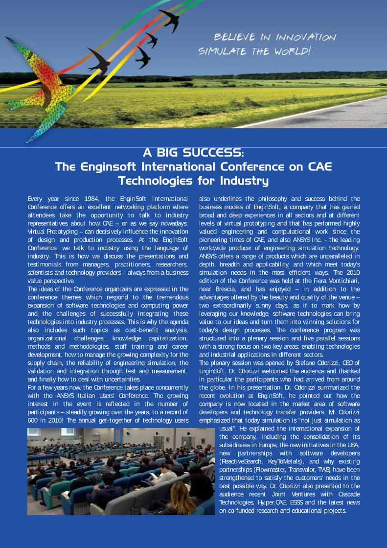
Every year since 1984, the EnginSoft InternationalConference offers an excellent networking platform whereattendees take the opportunity to talk to industryrepresentatives about how CAE – or as we say nowadays:Virtual Prototyping – can decisively influence the innovationof design and production processes. At the EnginSoftConference, we talk to industry using the language ofindustry. This is how we discuss the presentations andtestimonials from managers, practitioners, researchers,scientists and technology providers – always from a businessvalue perspective.The ideas of the Conference organizers are expressed in theconference themes which respond to the tremendousexpansion of software technologies and computing powerand the challenges of successfully integrating thesetechnologies into industry processes. This is why the agendaalso includes such topics as cost-benefit analysis,organizational challenges, knowledge capitalization,methods and methodologies, staff training and careerdevelopment, how to manage the growing complexity for thesupply chain, the reliability of engineering simulation, thevalidation and integration through test and measurement,and finally how to deal with uncertainties.For a few years now, the Conference takes place concurrentlywith the ANSYS Italian Users’ Conference. The growinginterest in the event is reflected in the number ofparticipants – steadily growing over the years, to a record of600 in 2010! The annual get-together of technology users
also underlines the philosophy and success behind thebusiness models of EnginSoft, a company that has gainedbroad and deep experiences in all sectors and at differentlevels of virtual prototyping and that has performed highlyvalued engineering and computational work since thepioneering times of CAE, and also ANSYS Inc. - the leadingworldwide producer of engineering simulation technology.ANSYS offers a range of products which are unparalleled indepth, breadth and applicability, and which meet today’ssimulation needs in the most efficient ways. The 2010edition of the Conference was held at the Fiera Montichiari,near Brescia, and has enjoyed – in addition to theadvantages offered by the beauty and quality of the venue –two extraordinarily sunny days, as if to mark how byleveraging our knowledge, software technologies can bringvalue to our ideas and turn them into winning solutions fortoday’s design processes. The conference program wasstructured into a plenary session and five parallel sessionswith a strong focus on two key areas: enabling technologiesand industrial applications in different sectors. The plenary session was opened by Stefano Odorizzi, CEO ofEnginSoft. Dr. Odorizzi welcomed the audience and thankedin particular the participants who had arrived from aroundthe globe. In his presentation, Dr. Odorizzi summarized therecent evolution at EnginSoft, he pointed out how thecompany is now located in the market area of softwaredevelopers and technology transfer providers. Mr Odorizziemphasized that today simulation is “not just simulation as
usual”. He explained the international expansion ofthe company, including the consolidation of itssubsidiaries in Europe, the new initiatives in the USA,new partnerships with software developers(ReactiveSearch, KeyToMetals), and why existingpartnerships (Flowmaster, Transvalor, TWS) have beenstrengthened to satisfy the customers’ needs in thebest possible way. Dr. Odorizzi also presented to theaudience recent Joint Ventures with CascadeTechnologies, Hy.per.CAE, ESSS and the latest newson co-funded research and educational projects.
A BIG SUCCESS:The Enginsoft International Conference on CAE
Technologies for Industry

Prof. Gianluca Iaccarino from Stanford University, and co-founder of Cascade Technologies, - a California-basedcompany that collaborates with EnginSoft – presented akeynote talk on high-fidelity multi-physics simulations,highlighting where and how these can have an incomparablevalue for industry, in applications such as gas-turbinecombustion, noise prediction and multi-phase flows ingeneral. Dr. Andreas Vlahinos from AES in Denver who nowcollaborates with EnginSoft Americas, presented an overviewof recent advances in infrastructural engineering and newconcepts for electric vehicles, by comparing differentscenarios through different approaches, also withmodeFRONTIER. The last keynote speaker Prof. Carlo Poloni,who with EnginSoft is one of the co-founders of ESTECO,showed why modeFRONTIER could be considered a ‘greentechnology’ tool, by giving an example built around a typicaltrip through Europe where the use of the software, asdemonstrated by some users, can positively affect the CO2
footprint.The ANSYS experts from the various sectors then informedthe audience about the latest developments of thetechnologies. They provided an update on the ANSYSproducts with exciting news for the users, and aroused thecuriosity of those who were not yet familiar with thesetechnologies. The conference ‘Gold Sponsors’, Microsoft, IBM andMathWorks, presented the final talks of the plenary session.In the parallel sessions and in the ‘poster session’ a wealthof about 100 papers by speakers from different industries,research institutions, academia and software producers waspresented.The exhibition has been well visited throughout the twoConference days. Attendees and exhibitors enjoyed pro-active talks sharing knowledge about new solutions and theirpossible applications, visions and strategies for the future,and discussed questions on complex CAE topics. Hands-onexperiences were provided in the demo sessions.The Conference has kept its promise and showed that itdeserves the trust of the participants, in the excellentcontent of the agenda and in the attitude of the organizers. Above all, the conference was also a get-together ofextraordinary people who brought not only engineeringknowledge to Brescia, but also enthusiasm, liveliness and awarmth, qualities that give the event every year, andespecially this year, a unique atmosphere and character.
CONFERENCE PROCEEDINGSThe EnginSoft International Conference 2010 Proceedings arenow available on CD. The CD includes more than 90 paperspresented during the different sessions of the event.To receive a copy of the CD, please email to:[email protected]
On 22nd and 23rd October this year, EnginSoft S.p.A.welcomed its Network Partners from France, Germany,Greece, Spain, Sweden & Nordic Countries, the UK andthe USA to the annual EnginSoft Partner Meeting atVilla Fenaroli in Rezzano, near Brescia.EnginSoft S.p.A. the mother company of the Network,welcomed for the first time, many of the new NetworkPartners from the USA: Cascade Technologies, StanfordUniversity, Advanced Engineering Solutions AES,Converged Mechanical Solutions and ESSS Brazil. The Partner Meeting offered an opportunity to exchangeexperiences and knowledge between the NetworkPartners, and with the EnginSoft experts. The 2 days sawa Get-together and lively discussions of different cultureswith a wealth of knowledge and diverse expertise in CAE,in various sectors.
The aim of the annual Meeting is to strengthen tiesbetween the Network nodes, to provide an update on thedifferent product and service portfolios of the Partners,and hence to leverage the Network’s resources to meetour customers’ needs and expectations in the bestpossible way!
EnginSoft Network met forPartner Meeting at VillaFenaroli
Network Partners from Europe, USA and Brazil met at Villa Fenaroli

Ogni anno, dal 1984, la Conferenza Internazionale diEnginSoft raccoglie il successo di un ‘format’ che, nell’ideaispiratrice, è sempre lo stesso: parlare all’industria di come lasperimentazione virtuale – il CAE, per utilizzare un termine dipiù lunga storia – possa contribuire in modo determinanteall’innovazione del processo progettuale, e, di conseguenza,dei processi produttivi. Parlare all’industria utilizzando illinguaggio dell’industria, che si sostanzia nelle testimonianzedegli operatori del settore – manager, direttori tecnici,utilizzatori, ma anche ricercatori, scienziati, e produttori ditecnologie – presentate in ottica di valore.
Se l’idea ispiratrice – singolare e caratterizzante, rispetto adaltri convegni del settore – è sempre la stessa, la suaespressione, e, quindi, i temi trattati, rispecchiano da un latol’evoluzione formidabile delle tecnologie software edell’hardware, e, dall’altro, i problemi e le opportunitàconnesse con la loro integrazione nei processi industriali. Siparla, quindi, di analisi costi-benefici, di aspettiorganizzativi, della capitalizzazione delle conoscenze, dimetodi e metodologie, della formazione del personale e dellecarriere, ma anche di come far fronte alla crescentecomplessità dei contesti e delle catene produttive,dell’affidabilità degli approcci della simulazione al computer,dei metodi per validarli e dell’integrazione con lasperimentazione diretta, del trattamento delleincertezze. Da alcuni anni, l’evento è svolto congiuntamentealla Conferenza Italiana degli utilizzatori di ANSYS.Ed il successo, misurabile nel numero deipartecipanti – in crescita ogni anno, e, quest’anno,oltre la soglia record dei 600! – segna, da solo, ilseguito che le due aziende hanno. EnginSoft, da unlato, per la vastissima esperienza in tutti i settoried a tutti i livelli cui si applica la simulazionevirtuale, e presente sul mercato sin dai tempipionieristici delle tecnologie software; ANSYSdall’altro, come principale produttore mondiale di
tecnologie, con un’offerta che non ha eguali percompletezza, applicabilità ed integrabilità. L’edizione 2010 del convegno si è tenuta al Centro Fiera delGarda di Montichiari presso Brescia, e ha goduto, oltre aivantaggi offerti dalla bellezza ed efficienza della sede, di duegiornate straordinarie di sole, quasi a rimarcare laprorompente evidenza di come, facendo leva sulleconoscenze – il cui ruolo è, e rimarrà, imprescindibile - letecnologie proposte possano portare in piena luce quanto,nei processi progettuali, può dar valore alle idee rendendolevincenti nella competizione industriale.
Il convegno è stato articolato in una sessione plenariaintroduttiva, ed in cinque successive sessioni parallele,organizzate secondo una matrice a due ingressi: quello delletecnologie abilitanti, e quello delle applicazioni industriali,distinte per settore.La sessione plenaria è stata aperta da Stefano Odorizzi,presidente di EnginSoft, che ha innanzitutto dato ilbenvenuto e ringraziato i partecipanti, in particolar modoquelli provenienti dai Paesi Europei, dagli Stati Uniti e dalGiappone. L’Ing. Odorizzi ha poi illustrato, in sintesi,l’evoluzione di EnginSoft e la sua collocazione nell’attualepanorama dei produttori e mediatori di tecnologie di settore,
UN GRANDE SUCCESSO:La Conferenza Internazionale EnginSoft
sulle Tecnologie CAE per l’industria

tenuto conto che, oggi, la simulazione non ècertamente più “just simulation ‘as usual’”. Ha cosìparlato dell’espansione dell’azienda a livellointernazionale, con il consolidamento delle filialieuropee, e l’avvio di nuove iniziative negli StatiUniti; delle nuove partnership con i produttori ditecnologie, sia in estensione di precedenticollaborazioni (Flowmaster, Transvalor, TWS), che invista di settori complementari a quelli trattati(ReactiveSearch, KeyToMetals); di recenti accordi ecointeressamenti societari (Cascade, Hy.per.CAE,ESSS, …); dei progetti di ricerca e per la formazionespecialistica e continuativa. Successivamente nella sessione plenaria ha parlato ilprof. Gianluca Iaccarino, dell’Università di Stanford,co-fondatore di Cascade, società californiana con cuiEnginSoft ha avviato un accordo di collaborazione. Egli haparlato di applicazioni multi-scala di “alta fedeltà”, e dicome queste possano avere, in alcune circostanze, valoreincomparabile per l’industria, discutendone attraversoesempi di grande evidenza nella simulazione dellacombustione, del rumore, e dei flussi multi-fase.
Dopo di lui, Andreas Vlahinos, di AES, Denver, e,recentemente, collaboratore di EnginSoft Americas, hapresentato uno studio sull’attualità dei veicoli alternativi –veicoli elettrici, rispetto a diversi modelli di infrastruttureper la ricarica delle batterie – ponendo a confronto diversiscenari, confrontati utilizzando modeFRONTIER. Carlo Poloni,fondatore, con EnginSoft, di ESTECO, ha chiuso la serie degliinterventi mostrando come modeFRONTIER possa essereconsiderato una ‘tecnologia verde’, proponendo, con unvivace esempio preso dalla quotidianità di un viaggioattraverso l’Europa, di misurare la riduzione di emissioni diCO2 imputabile all’applicazione dell’ottimizzazione nellaprogettazione.
È stata, poi, la volta di ANSYS, che, con un interventoarticolato tenuto dagli esperti dei diversi settori, haaggiornato sulla nuova versione dei prodotti, ingolosendo gliutilizzatori, ed incuriosendo quanti, nell’assemblea, nonavessero ancora familiarità con le tecnologie proposte. I“gold sponsor” del convegno, Microsoft, IBM e MathWorks,hanno, infine, concluso la sessione.
Successivamente, nelle sessioni parallele – e nella “postersession” – sono state presentate un centinaio di relazioni,contribuite da esponenti del mondo dell’industria,dell’università e della ricerca scientifica. Le relazioni sonodisponibili negli atti del convegno.È stata molto apprezzata, infine, l’area fieristica dove ipartecipanti al convegno hanno avuto modo di discutere congli espositori, prendendo visione delle loro soluzioni estrategie di sviluppo, di porre domande specifiche e ditoccare con mano, nelle dimostrazioni, la qualità el’estensione delle applicazioni offerte.
Complessivamente, anche quest’anno il convegno hamantenuto le promesse, meritando la fiducia che ipartecipanti – sia i fedelissimi che quelli intervenuti per laprima volta – hanno accordato agli organizzatori. Ma ilconvegno è stato anche un incontro straordinario di persone,che con la loro vivacità, entusiasmo e calore hanno conferitoall’evento un carattere ed uno stile unico nel corso deglianni.
ATTI DELLA CONFERENZAÈ disponibile il CD degli atti EnginSoft InternationalConference 2010, contenente oltre 90 paper presentatinelle varie sessioni della Conferenza.Per ricevere una copia del cd inoltrare una richiesta viaemail a: [email protected]
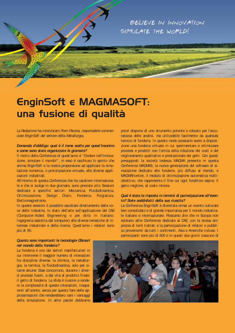
La Redazione ha intervistato Piero Parona, responsabile commer-ciale EnginSoft del settore della Metallurgia.
Domanda d’obbligo: qual è il tema scelto per quest’incontroe come sono state organizzate le giornate?Il motto della Conferenza di quest’anno è “Credere nell’innova-zione, simulare il mondo!”, in esso è racchiuso lo spirito cheanima EnginSoft e la nostra propensione ad applicare la simu-lazione numerica, o prototipazione virtuale, alle diverse appli-cazioni industriali.All’interno di questa Conferenza che ha carattere internaziona-le e che si svolge in due giornate, sono previste otto Sessionidedicate a specifici settori: Meccanica, Fluidodinamica,Ottimizzazione, Design Chain, Fonderia, Forgiatura,Elettromagnetismo.In queste sessioni è possibile ascoltare direttamente dalla vo-ce delle Industrie, lo stato dell’arte sull’applicazione del CAE(Computer-Aided Engineering o per dirlo in Italiano:Ingegneria assistita dal computer) alle diverse tematiche di in-teresse industriale e della ricerca. Quest’anno i relatori sonopiù di 90.
Quanto sono importanti le tecnologie Œsmartnel mondo della fonderia?La fonderia è uno dei settori manifatturieri incui interviene il maggior numero di interazionifra discipline diverse: la chimica, la metallur-gia, la termica, la fluidodinamica, solo per ci-tarne alcune. Esse concorrono, durante i diver-si processi fusori, a dar vita al prodotto finale:il getto di fonderia. La sfida è riuscire a rende-re la complessità di queste interazioni, traspa-renti all’utente, senza per questo fare delle ap-prossimazioni che renderebbero vani i vantaggidella simulazione. In altre parole dobbiamo
poter disporre di uno strumento potente e robusto per l’accu-ratezza delle analisi, ma utilizzabile facilmente da qualsiasitecnico di fonderia. In questo modo possiamo avere a disposi-zione una fonderia virtuale in cui sperimentare e ottimizzareprocessi e prodotti con l’ottica della riduzione dei costi e delmiglioramento qualitativo e prestazionale dei getti. Con questipresupposti la società tedesca MAGMA presenta in questaConferenza MAGMA5, la nuova generazione del software di si-mulazione dedicato alle fonderie, più diffuso al mondo, eMAGMAfrontier, il modulo di ottimizzazione automatica multi-obiettivo, che rappresenta il fine cui ogni fonditore aspira: ilgetto migliore, al costo minore.
Qual è stata la risposta in termini di partecipazione all’even-to? Siete soddisfatti della sua riuscita?La Conferenza EnginSoft è diventata ormai un evento culturaleben consolidato e di grande importanza per il mondo industria-le italiano e internazionale. Possiamo dire che in Europa nonesistano altre Conferenze dedicate al CAE, con la stessa am-piezza di temi trattati e la partecipazione di relatori e pubbli-co provenienti da tutti i continenti, Asia e Americhe incluse. Ipartecipanti sono più di 600 e in questi due giorni ciascuno di
EnginSoft e MAGMASOFT: una fusione di qualità

essi ha la possibilità di seguire le sessioni tema-tiche che più lo interessano, i workshop appli-cativi dei software, i forum con gli esperti diogni tecnologia, e visitare gli stand degli spon-sor, che quest’anno sono circa una ventina.
Ci può riassumere quali sono le tematicheprincipali emerse in questi due giorni?Per quanto riguarda la fonderia, molti sono sta-ti i temi affrontati provenienti sia dal settoredei metalli non-ferrosi che da quello dei ferrosi.Per quanto riguarda i non-ferrosi lo studio di progettazionebergamasco SPS ha trattato l’importante argomento della simu-lazione come ausilio alla progettazione degli stampi da presso-colata e ad esso si è collegato quello della fonderia friulanaFriulpress, anch’esso dedicato alla pressocolata, ma questa vol-ta con l’esposizione di uno studio di Ottimizzazione automati-ca con MAGMAfrontier per il miglioramento qualitativo di ungetto per il settore motociclistico. Sempre al settore dei nonferrosi appartiene la relazione tenuta dal Prof. L. Kalliendell’Università di Aalen, che ha fatto una panoramica entusia-smante degli attuali settori sui quali il suo gruppo sta lavoran-do, soprattutto per la pressocolata, e come la simulazione conMAGMASOFT venga largamente utilizzata per la formazione dibase degli ingegneri di fonderia. Per quanto riguarda i metalliferrosi, l’Università Politecnica delle Marche con l’ing. MichelaSimoncini, ha presentato un interessante studio di ri-progetta-zione delle modalità di colata in shell moulding di anelli in ghi-sa in cui MAGMAiron è stato fondamentale per il miglioramen-to della qualità dei getti, l’aumento della resa per colata e laprevisione delle caratteristiche meccaniche finali del getto. Lafonderia veneta VDP ha relazionato invece su un innovativoprogetto che integra la previsione dei difetti con MAGMAiron inun sistema di progettazione automatica per il dimensionamen-to delle colate e del sistema di alimentazione dei getti, con losvolgimento di prove sperimentali che hanno dimostrato labontà delle simulazioni rispetto alla realtà di fonderia.Particolarmente stimolante e originale è stato poi l’interventodella fonderia piemontese Perucchini, che occupandosi di unatecnologia di nicchia come quella dello shell moulding, ha par-lato dell’uso della simulazione MAGMASOFT in chiave marketingper dimostrare ai potenziali clienti la bontà tecnica ed econo-
mica di questo processo, rispetto ad altri processi più conven-zionali. La giornata è proseguita con la nuova versioneMAGMA5.1 dedicata a tutti i processi con stampo metallico,quindi parliamo di pressocolata, bassa pressione e conchigliain gravità, che ha suscitato notevole interesse per la sua inno-vativa modalità di impostazione delle analisi e facilità d’uso,grazie anche alle nuove interfacce dirette con CATIA, ProE e iprincipali CAD. La possibilità di prevedere la durata degli stam-pi prima dell’insorgere in essi delle cricche da fatica termica, ela previsione delle caratteristiche meccaniche dei getti in legaleggera, grazie all’uso di un nuovo modello micro-strutturale, èstato recepito come una reale innovazione che potrà portare anotevoli vantaggi economici per le fonderie. L’ottimizzazioneautomatica, la simulazione della formatura delle anime, deiprocessi Disamatic e Shell moulding, la simulazione dei tratta-menti termici e la previsione dell’andamento delle tensioni edeformazioni del getto durante l’intero ciclo di trattamento,sono stati altri argomenti che sono stati accolti con grande in-teresse a saranno sicuramente oggetto di applicazione imme-diata da parte di molte delle fonderie intervenute, con delleimmediate ricadute sulla qualità dei getti prodotti. Ed è pro-prio questo il fine di questa Conferenza: rendere fruibili nel la-voro quotidiano di ogni azienda lo “stato dell’arte” del CAE, perfavorire con esso, l’innovazione e la competitività sul mercato.
Intervista a Piero ParonaEnginSoft
Intervista pubblicata su Pressocolata e Tecniche FusorieAnno 2010 - Num. 2

12 - Newsletter EnginSoft Year 7 n°4
Pierburg Pump Technology (PPT) is a company specializingin the development and the production of mechanical andelectrical oil pumps, mechanical and electrical water pumpsand vacuum pumps. PPT is collaborating with most of the automakers worldwidein order to develop new products that fulfil therequirements of the Euro5 and Euro6 standards.
Remarkably, these environmental restrictions have caused aradical change in the design of oil pumps which now mustbe able to optimize the engine lubrication while at thesame time reducing the fuel consumption. In order toachieve this, PPT is developing the new generation of oilpumps based on the new vane concept with variabledisplacement (VOP), instead of the traditional gear design.In fact, through this design revolution, PPT, as well as someother competitors leader in the pumps development for the
automotive market, could provide fuel consumptionreductions of up to 2.5%, with corresponding CO2
reductions. Nevertheless, these vane pumps are significantlymore complex and less robust of the traditional geared onesand for this reason, they require a long engineering phasein which the support of the most advanced simulationstechnologies is even more important every day.
An example of the PPT engineering approachAs an example of the PPT engineering approach, wedescribe here the activities of the Calculation andSimulation group during the development of an oil pumpfor a new Euro5 engine. These activities involve bothcalculation and testing. Based on the requirements of thecustomer, one of the world’s leading automakers – theR&D group of PPT has decided to develop, a vane oil pumpwith variable displacement in order to achieve therequired fuel consumption reduction while maintainingthe same performance level as is provided by a traditionalpump. This VOP pump was designed for a new gasolineengine; this new engine was based on an existing engine,but with a modified injection system, the power has beendoubled.
During this design phase, the PPT team made allpreliminary verifications of the design following theinternal standard calculation procedure, using on bothcommercial and in-house software. This procedure is basedon both commercial and in-house software and allows thedesign team to verify that the pump is well-designed fromthe standpoints of kinematics, dynamics, hydraulics andstructural. Early testing of prototypes confirmed asuccessful design, however there were some failuresobserved in a following validation phase when installedon the actual engine.
In particular, the breakages have affected the pump rotorthat cracked generally at 1/3 of the total tests durationor, in some cases, even before. As a first step, a SEMinvestigation of the cracked surfaces of the parts havebeen performed in order to investigate deeper the failuremode and to guess the main causes of breakages. Throughthis investigation it has been clarified that the failureshave been the result of a classical fatigue phenomenonwhich starting point is likely located on the rotor-crankshaft (CS) engagement face, where the surfaces havealso a ductile aspect due to the several impact loadsbetween the two parts.
Reliability Evaluations of an InnovativeOil Pump under Crankshaft TorsionalVibrations
Fig. 1 - A crack in the VOP rotor after the engine test
Fig. 2 - Magnification of the worn and cracked rotor engagement face

Newsletter EnginSoft Year 7 n°4 - 13
The simulation workBased on these results, a complete calculation loopinvolving hydraulic, kinematic, dynamic and structuralevaluations was conceived by the R&D simulation group inorder to verify the suspicion that the crankshaft’s irregularmotion could be the main cause of the failures. Although,even if some preliminary calculations wereperformed in the design phase, it wasabsolutely necessary to investigate whetherthe crankshaft torsional vibrations, whichwas not included in the previousverification simulation, could significantlyincrease the level of load in the VOP. Inorder to do so, the CS acyclisms in variousworking conditions were measured by thecustomer, readily verifying easily that theirregularity of the motion in the “new”Euro5 engine was much higher than that inthe “old” Euro4 [2].
Moreover, some CFD analyses were carriedout, to estimate the oil pressure level andto verify that no unwanted fluidodynamic
effects were taking place while the pumpwas working [3]. Based also on theseresults, some MB simulations wereperformed modelling the complete oil pumpand applying as external loads the oildelivery pressures previously estimatedthrough the CFD analyses. Through thismodeling and the imposition of the torsionalvibrations on the CS, the dynamic forcesbetween the VOP parts in presence ofacyclisms have been estimated.
In this way also the contact forces betweenthe rotor and the crankshaft, which shouldbe the main cause of the rotor failures, havebeen evaluated in several workingconditions [1]. Moreover, the detailed
analysis of these loads has clarified that the “Evo” enginecauses a dramatic increase of in the CS-rotor impacts dueto its high motion irregularity. As confirmation of this, themaximum values of the CS-rotor contact forces have beenestimated to be 5 times higher for the Euro5 engineapplication than the ones of the Euro4.
Fig. 3 - Comparison of the CS torsional vibrations for the Euro4 and Euro5 engines
Fig. 4 - CS-rotor contact forces and rotor speeds vs CS rotation angle from MBs
Fig. 5 - CFD evaluation of the VOP oil pressure Fig. 6 - Equivalent stress in the rotor from FEAs
14 - Newsletter EnginSoft Year 7 n°4
The forces evaluated in this way were then used toperform an FEM simulation in order to evaluate their effecton the stress level in the rotor in general and in the rotor-crankshaft interface in particular. In order to do so, the dynamic problem schematized in theMB has been reduced to an equivalent static one applyingthe “d’Alembert Principle” [4-5], so that the inertialtorques are distinguished from the reaction torque due tothe constraints and the loads. For this reason, the forces,the angular accelerations and the friction and inertiatorques in specific high-stressing instants have beenrecollected from the MB and implemented in ANSYS. TheFEM simulations so completed have confirmed that thecrack initiation starts on the rotor engagement surface incontact with the CS. Remarkably, the FEAs have also demonstrated that thefailures are essentially caused by the abnormal loadscoming from the engine and not by a lack of robustness inthe rotor. As further confirmation of this, the level of
stress in the current Euro4 application has been estimatedthrough the repetition of the MB and FEA calculations,confirming that the dramatic increase of the enginemotion irregularity could cause rotor breakages for thepump already in production also.
The rotor redesign to avoid the failuresIn addition to this, the calculations loop here describedhas enabled the evaluation of the possible benefits ofsome design modifications through the repetition of theMBs and the FEAs. In particular, the variation of the CS-rotor clearance at the engagement surfaces, the increaseof the critical strength section of the rotor and increase ofthe number of the engagement surfaces have beenevaluated as possible modifications for the reduction ofthe stresses in the rotor.
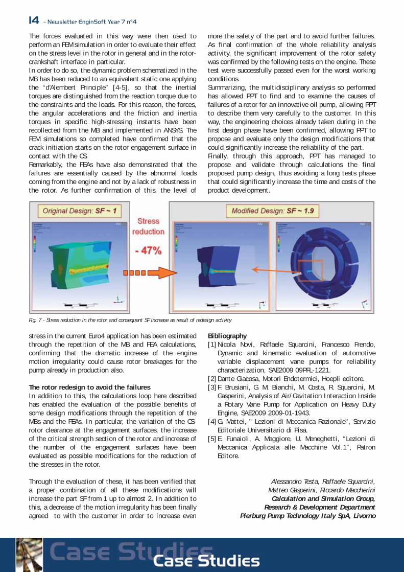
Through the evaluation of these, it has been verified thata proper combination of all these modifications willincrease the part SF from 1 up to almost 2. In addition tothis, a decrease of the motion irregularity has been finallyagreed to with the customer in order to increase even
more the safety of the part and to avoid further failures.As final confirmation of the whole reliability analysisactivity, the significant improvement of the rotor safetywas confirmed by the following tests on the engine. Thesetest were successfully passed even for the worst workingconditions.Summarizing, the multidisciplinary analysis so performedhas allowed PPT to find and to examine the causes offailures of a rotor for an innovative oil pump, allowing PPTto describe them very carefully to the customer. In thisway, the engineering choices already taken during in thefirst design phase have been confirmed, allowing PPT topropose and evaluate only the design modifications thatcould significantly increase the reliability of the part.Finally, through this approach, PPT has managed topropose and validate through calculations the finalproposed pump design, thus avoiding a long tests phasethat could significantly increase the time and costs of theproduct development.
Bibliography[1]Nicola Novi, Raffaele Squarcini, Francesco Frendo,
Dynamic and kinematic evaluation of automotivevariable displacement vane pumps for reliabilitycharacterization, SAE2009 09PFL-1221.
[2]Dante Giacosa, Motori Endotermici, Hoepli editore.[3]F. Brusiani, G. M. Bianchi, M. Costa, R. Squarcini, M.
Gasperini, Analysis of Air/Cavitation Interaction Insidea Rotary Vane Pump for Application on Heavy DutyEngine, SAE2009 2009-01-1943.
[4]G. Mattei, " Lezioni di Meccanica Razionale", ServizioEditoriale Universitario di Pisa.
[5]E. Funaioli, A. Maggiore, U. Meneghetti, “Lezioni diMeccanica Applicata alle Macchine Vol.1”, PatronEditore.
Alessandro Testa, Raffaele Squarcini, Matteo Gasperini, Riccardo MaccheriniCalculation and Simulation Group,
Research & Development DepartmentPierburg Pump Technology Italy SpA, Livorno
Fig. 7 - Stress reduction in the rotor and consequent SF increase as result of redesign activity

Newsletter EnginSoft Year 7 n°4 - 15
In the last decade, great attention has been devoted to thestudy of Metamaterials. The electromagnetic properties ofhomogeneous materials arise from the microstructure andchemical composition of the material. These properties,generally measured by permittivity and permeability, dictatethe response of the material to external electric andmagnetic fields, respectively. Artificial electromagneticmaterials are man-made composite structures which exhibitproperties not found in natural bulk materials. Compared to the artificial electromagnetic materials, inartificial impedance surfaces the structure is bound into twodimensions.
These surfaces can control the propagation or theboundary conditions of electromagnetic fields andare generally referred as High Impedance Surfaces(HIS). The basic configuration of a metamaterialgenerally comprises an arrangement of metalelements of on a periodic lattice which are printed ona planar grounded dielectric slab.
High impedance surfaces can be exploited to realizeElectromagnetic Bandgap (EBG) structures, whichprevent surface wave propagation within the so-called forbidden band, and Artificial MagneticConductors (AMC), which approximate the behaviorof a Perfect Magnetic Conductor (PMC). Theelectromagnetic behavior of these surfaces can betailored by using a proper design of the basicelement shape and size, a suitable value of theperiodicity and a correct choice of the dielectricproperties and thickness of the single or multipledielectric slabs employed for the structure.
These HISs are mainly used at microwave and (sub)millimeter wave frequency and provide surface wavesuppression, improve antenna performance for modernwireless communication systems, limit the interferenceamong adjacent devices, realize enhanced radar absorbingmaterials, and foster novel microwave circuits andwaveguide designs.
In this work the unique properties of metamaterials will beshown by using some examples regarding the suppression ofsimultaneous switching noise and the implementation ofnovel radar absorbing materials.
Design of metamaterial based devicesfor electromagnetic applications
Fig. 1 - Three-dimensional sketch of the analyzed configuration (a) and a picture of a manufactured wideband absorber.
Fig. 2 - Reflection coefficient of the ring FSS over a grounded air slab of 5mm. Theresults obtained by Ansoft HFSS are compared both with MoM simulations and with anequivalent circuit approach.
16 - Newsletter EnginSoft Year 7 n°4
Radar Absorbing MaterialsThe absorbing panel consists of a conventional highimpedance surface comprising lossy frequency selectivesurfaces over a thin grounded dielectric slab [1]. The FSSarray, made up of capacitive cells, behaves as a capacitor inthe low frequency region but its impedance becomesinductive after the first resonance. Let us consider an FSScomposed by a ring array, with a periodicity D equalto 11 mm and a surface resistance Rs of 70 Ω/sq,printed on a air grounded dielectric substrate with athickness of 5 mm (see Fig. 1). In Fig. 2 thereflection coefficient of the absorber obtained by aperiodic MoM code, by the equivalent circuitapproach and by Ansoft HFSS v.10 is reported.
The absorbing structure provides remarkableperformance (-15 dB in the band from 7 GHz to 20GHz) with an overall thickness of only 5 mm. Thethickness of the absorber for obtaining the shownabsorption profile approaches the physical limitationof the non-magnetic RAM [2]. Indeed, in this case,the minimum theoretical thickness is 4.5 mm.
This performance cannot be accomplished bylightweight configurations employing optimizedJaumann screen [3] or by other commerciallyavailable non-magnetic multilayer structures (see forinstance [4]) with a thickness lower than 9-10 mm.Despite the intrinsic periodicity of the structure, itsdimension can be reduced down to a 4 by 4 arraypreserving almost the same absorption performances,with respect to a PEC plate of the same dimensions.The absorber here presented does not redirect theenergy in other directions as in other RAM designs[5] but it dissipates the incoming power by realizing
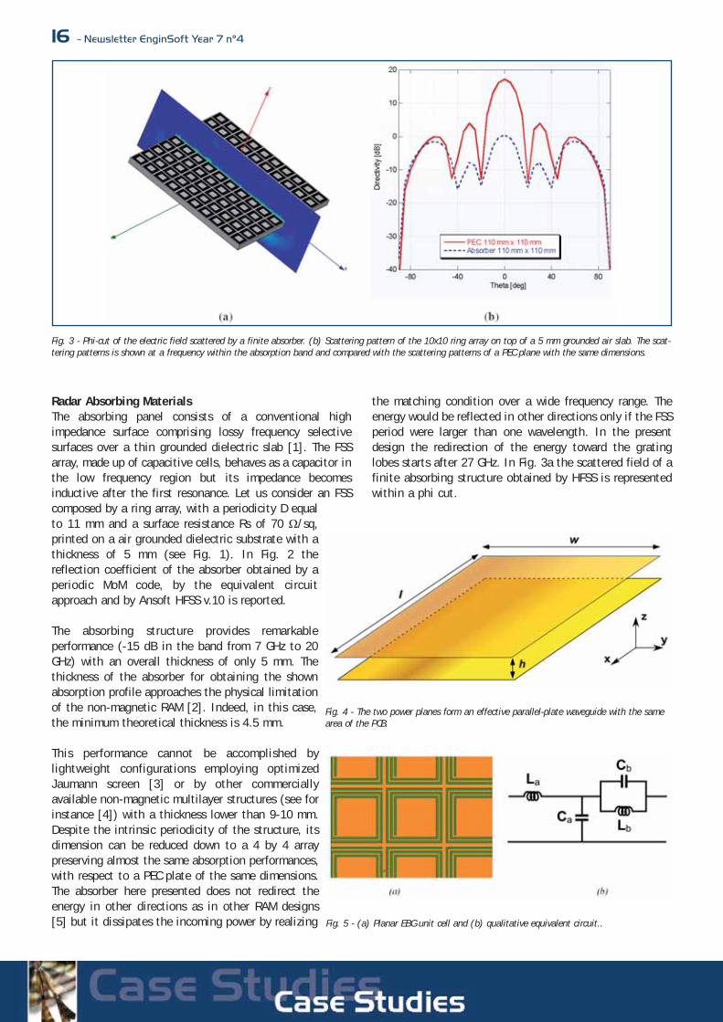
the matching condition over a wide frequency range. Theenergy would be reflected in other directions only if the FSSperiod were larger than one wavelength. In the presentdesign the redirection of the energy toward the gratinglobes starts after 27 GHz. In Fig. 3a the scattered field of afinite absorbing structure obtained by HFSS is representedwithin a phi cut.
Fig. 3 - Phi-cut of the electric field scattered by a finite absorber. (b) Scattering pattern of the 10x10 ring array on top of a 5 mm grounded air slab. The scat-tering patterns is shown at a frequency within the absorption band and compared with the scattering patterns of a PEC plane with the same dimensions.
Fig. 4 - The two power planes form an effective parallel-plate waveguide with the samearea of the PCB.
Fig. 5 - (a) Planar EBG unit cell and (b) qualitative equivalent circuit..

Newsletter EnginSoft Year 7 n°4 - 17
The graph shows that the energy is dissipated by thestructure and not redirected in other directions. Thereflected patterns both for a metallic square of 110 mm x110 mm and for the presented absorbing structure with thesame dimension (10 x 10 unit cells) in correspondence of afrequency inside the absorption band are reported in Fig.3b. The radiation pattern has been obtained by using theHFSS full wave simulator.
The manufactured structure results in a very lightweightconfiguration, indeed a 30 cm × 30 cm sample weighs 10 gcompared with the 450 g of a commercial magneticallyloaded absorber (Eccosorb [6]) with the same dimensions.
Metamaterials for Simultaneous Switching Noise SuppressionThe recently emerged system-on-package (SoP) technologyprovides low-cost and compact digital circuits forcommunication devices, sensors or high-speed modules; SoPrequires highly integrated systems [7][8]. This is obtainedby integrating multiple dies and passive devices onsubstrates which are stacked in three dimensions andinterconnected laterally or vertically onto the packagesubstrate. The use of vias as interconnection structures inhigh-density System on Package substrates and PrintedCircuit Boards (PCBs) is the most common solution to routesignals in these multilayer structures. These closely-spacedinterconnections may become sources of high-frequencynoise and generate coupling wich affects both signal andpower integrity. This can cause serious problems regardingelectromagnetic interference (EMI) and electromagneticcompatibility (EMC) control.
In fact, as a result, the noise reduces the achievableperformance, worsens the bit error rate (BER) and greatlylowers the system reliability. Active devices are generallyconnected between two planes or can be linked to thesignal layer by using through-vias. These two planes, whichhave the same area as the PCB, can be considered as anideal parallel-plate waveguide (Fig. 4), where the dimensionin the y-direction is assumed to be much larger than thethickness h and therefore any variation along the
x-direction can be neglected. When a high-speed deviceswitches, a sudden time-varying currents changes thecurrent consumption and a voltage wave arises andpropagates along the two planes, causing the so calledSimultaneous Switching Noise (SSN), which produces falseswitching in digital circuits and malfunctioning in analog
Fig. 6 - Planar EBG structure with test ports for S parameter evaluation.
Fig. 7 - Numerical result of the magnitude of S21 parameter.
Fig. 8 - Numerical result of the magnitude of S31 parameter.
Fig. 9 - Numerical result of the magnitude of S41 parameter.

18 - Newsletter EnginSoft Year 7 n°4
circuits. The guiding structure reported in Fig.4 can supporttransverse electric (TE), transverse magnetic (TM) andtransverse electric and magnetic (TEM) modes [9].
Since the typical thickness of the commercially availablePCBs is on the order of few millimetres (1 mm – 5 mm), thecut-off frequencies for TE and TM modes are very high (onthe order of hundred of gigahertz) hence the only modes ofconcern are the dominant waves of TEM modes with the cut-off frequency corresponding to that of the TM0. In additionto this, since practical power planes have finite width andlength it is also important to consider the resonance modesTEmnp and TMmnp excited in the structure given by:
Since h is very small with respect to w and l, only TEmn0 andTMmn0 modes have to be investigated. It is therefore ofparamount importance to suppress the resonant modesinduced in the parallel-plate waveguide of finite length andwidth.
Our aim is to design a metamaterial which is able to inhibitthe propagation of the SSN within a large bandwidth (from1.0 GHz to 6.6 GHz) with a good suppression level (lessthan -30 dB) and also along a wide range of directions. Morespecifically, we look at to the employment of anElectromagnetic Bandgap (EBG) structure which preventsthe propagation within a specific frequency band. The EBGunit cell is shown in Fig. 5a. The size is 30 mm x 30 mm andthe gap between the lines is equal to 1 mm. A simple modelfor the qualitative behaviour of the unit cell is presented inFig.5b.
This equivalent circuit with lumped elements contains acapacitance Ca and an inductance La which take into accountthe interaction between the EBG patch and the continuousplane. The second part refers to the thin line connecting theinner patch of each unit cell to the other part of thestructure (Lb) and the capacitance Cb produced by the gapsbetween neighbouring cells.
The addressed power/ground plane with the planar EBGprinted on the upper layer comprises 3 x 3 unit cells. Thewhole dimension is 90 mm x 120 mm as reported in Fig. 6,where the ports used for S parameter evaluation areindicated. The two conductive layers are placed at the topand down face of a slab of FR4 dielectric material (εr=4.4,tg loss=0.02). The thickness considered for the dielectriclayer is 1.54 mm.
The behaviour of the structure is probed at four points bymeans of lumped ports. Each lumped port used to test theSSN suppression is located at the inner patch centre. Theemployment of four ports makes it possible to check the
different level of suppression for different directions ofpropagation along the EBG structure. As a reference, wecompare the EBG performance with a two-layer solid powerplane. All the simulated results were obtained using theAnsoft High Frequency Structure Simulator (HFSS). In Fig. 7,Fig.8 and Fig.9 there are reported comparisons between theattenuation realized by the structure along the pathconnecting various connecting ports. The magnitude of theparameter S21 is maintained below -30 dB over thebandwidth starting from around 1.0 GHZ up to 6.6 GHz forall the investigated cases.
References[1] F. Costa, A. Monorchio, G. Manara “Analysis and Design
of Ultra Thin Electromagnetic Absorbers ComprisingResistively Loaded High Impedance Surfaces”, IEEETrans. on Antennas and Propagation, vol. 58, no. 5,2010.
[2] Rozanov, K. N., “Ultimate Thickness to Bandwidth Ratioof Radar Absorbers,” IEEE Trans. on Antennas andPropagation, vol. 48, no. 8, pp. 1230-1234, 2000.
[3] B. Chambers and A. Tennant, “Optimized design ofJaumann radar absorbing materials using a geneticalgorithm,” Inst. Elect. Eng. Proc. Radar Sonar Navigat.,vol. 143, pp. 23–30, Jan. 1996.
[4] Laird Tecnologies Company, http://www.lairdtech.com/Products/EMI-Solutions/Specialty-EMI-Solutions/Microwave-Absorbers/.
[5] Paquay, M. Iriarte, J.-C. Ederra, I. Gonzalo, R. de Maagt,P., “Thin AMC Structure for Radar Cross-SectionReduction”, IEEE Trans. on Antennas and Propagation,vol. 55, no. 12, pp. 3630-3638, 2007.
[6] Emerson and Cuming Microwave product, 28 York AvenueRandolph, MA 02368 USA,http://www.eccosorb.com/main/Home.html.
[7] R. R. Tummala, M. Swaminathan, M. M. Tentzeris, J.Laskar, G.-K. Chang, S. Sitaraman, D. Keezer, D. Guidotti,Z. Huang, K. Lim, L. Wan, S. K. Bhattacharya, V.Sundaram, F. Liu, and P. Markondeya Raj,“The SoP forminiaturized, mixed-signal computing,communication,and consumer systems of the nextdecade,” IEEE Trans. Adv. Packag.,vol. 27, no. 2, pp.250–267, May 2004.
[8] T. Sudo, H. Sasaki, N. Masuda, and J. L. Drewniak,“Electromagnetic interference (EMI) of system-on-package (SoP),” IEEE Trans. Adv. Packag., vol. 27, no. 2,pp. 304–314, May 2004.
[9] D. Pozar, Microwave Engineering, 2nd ed., New York:Wiley, 1998.
Agostino Monorchio, Simone Genovesi, Filippo Costa University of Pisa, Dipartimento di Ingegneria
dell’Informazione: Elettronica, Informatica,Telecomunicazioni - Pisa, Italy

Newsletter EnginSoft Year 7 n°4 - 19
High power energy storage systems are necessary for the newage of electric vehicles. Lithium ion batteries have theadvantage of high energy density, good aging characteristicsand high efficiency, but at the same time their thermal range ofoperation is limited. With temperatures under 0°C, the powercapacity of the lithium battery is reduced about 70% and witha temperature over 40°C, irreversible damage can occur over70°C there can also be thermal runaway. Hence efficient andaccurate thermal management is necessary.The battery cooling system shown in Fig 1 is analyzed anddesigned with the aid of numerical tools. We use a modelingmethodology starting with CFD and ending at a low dimensional
but accurate compact thermal model for system level simulation.This model is ready to be coupled with other physical domainslike electrical, chemical and mechanical. Detailed CFD simulationis performed to analyze the air flow over corrugated channels.Heat transfer coefficients are calculated with CFD and then usedin a finite element (FEM) thermal model of a Li-Ion battery packwith one-dimensional flow (FLUID116).The finite element thermal model is, however, incompatible withsystem level simulation, since it is high dimensional and itstransient simulation takes too much time. We use modern modelreduction (see Fig 2) in order automatically to develop anaccurate compact thermal model of the battery pack.After that we use a semi-physical electrical model of the battery.It is based on electrochemical equations developed by the groupof Prof Newman (DualFoil), but with simplified assumptions tospeed model simulation. The parametersof the model still have some physicalmeaning but they should be determinedduring a parameterization procedure.The system level thermal model iscoupled with an electrical battery cellmodel in Simplorer (see Fig 3 left). Forsimplicity, only three cells that arecoupled with the battery pack areshown. A sub-circuit model describes
the cell model (see Fig 3 right). Theelectrical model is implemented in VHDL-AMS language.
The effect of discharge current is evaluatedin 25Ah cells connected in series in 1,5 and10 C-rates, see Fig. 4. Losses effects arepresent in higher currents showing areduced total capacity and lower voltage,which can be observed in the voltageprofiles.
L. Kostetzer; S. Nallabolu; E. RudnyiCADFEM GmbH, Grafing bei München, Germany
For more information, please contact: Mr Erke Wang - [email protected]
Electro-thermal simulation for EV/HEV applications
Fig. 1 - The battery pack model (http://www.lionsmart.de/)
Fig. 2 - The idea of model order reduction (http://ModelReduction.com)
Fig. 3 - Electro-thermal battery coupling in Simplorer
Fig. 4 - Voltages and temperatures in constant current discharge

20 - Newsletter EnginSoft Year 7 n°4
At NASA Langley Research Center, a program called Drones forAerodynamics and Structural Testing-DAST was carried out togenerate an extensive database of measured steady andunsteady pressure data to be used in validation ofcomputational aero-structural studies. The data concerning thecomposite aeroelastic research wing (ARW-2) presented in thisprogram has been used as a benchmark problem by manyresearchers in the past mostly with simplified models. However,the structural definition of the composite skin as presented inliterature is not complete enough to create a 3D "Finite ElementModel" of the wing skin to use in validation of computationalstudies today. Thus, a computational composite ARW-2 wingmodel which has the similar structural response with theexperimental wing should be identified to be used in high-fidelity computations. ARW-2 composite skin is made offiberglass material with honeycomb panels sandwiched betweenthe middle two layers of fiberglass. Moreover, the thicknesses ofribs, spars, skin and axial bars of the wing are still missinggeometrical properties. Several experimental studies about ARW-2 wing exist inliterature. Sanford [1] provides geometrical and structuralproperties of the ARW-2 wing. Sanford [2] also presentedexperimental studies for steady state conditions in order togenerate extended database for the ARW-2 wing. Unsteadytransonic aerodynamic characteristics of the ARW-2 wing aregiven in Seidel's [3] experimental work. In addition,computational studies concerning the ARW-2 wing have beenpresented by Cohen [4] and Bhardwaj [5]. Bhardwaj created a 3Dthe ARW-2 wing model with isotropic skin and verified the ARW-2 computational wing model for static aeroelastic analysis in thetransonic regime. Farhangnia [6] performed static and dynamicAeroelastic analysis by using an aeroelastic code ENSAERO whichwas also used by Bhardwaj. Farhangnia modeled the wingstructure as a composite plate. A 3D computational isotropicARW-2 wing model which has a compatible structural responsewith the experimental wing was identified in a former study andalso aeroelastic validation and multi-disciplinary optimization ofthis isotropic ARW-2 wing model was performed by Nikbay andAysan [7]. In this paper, a further study is carried on identifyinga 3D structural model of ARW-2 wing with composite skinparameters by taking into account only bending, torsional
responses and modal analysis. The aim of the whole study is tocome up with a reliable computational ARW-2 model withcomposite skin which is validated in both structural andaeroelastic responses to be used in benchmark studies. Thisidentification process utilises an inverse engineering approachbased on a multi-objective optimization algorithmmodeFRONTIER 4.1 driving a structural finite element solver,Abaqus 6.7.NASA's ARW-2 wing had three different supercritical airfoils inorder to investigate the interaction between the flexible, orelastic wing and the aerodynamic forces experienced duringflight in transonic regime [1]. The geometric model created viathe software CATIA V5R17 is shown in Figure 1.The spars and ribs were machined from 7075-T73 aluminumalloy. In Table 1, mechanical properties of Aluminum 7075-T73are presented.
The ARW-2 wing composite skin was made of fiberglass materialwith honeycomb panels sandwiched between the middle twolayers of fiberglass for areas of skin not located over the sparsor ribs. The number of layers of fiberglass used to make the skinvaried from 36 at the inboard end to 27 at the outboard end,with approximately 25 % of the layers at ±45 degree orientation[3]. By using these definitions, the wing skin is divided into twoas inner and outer surfaces. The honeycomb core is located atthe center of these surfaces. The ±45 degree plies are locatedaround the honeycomb core, symmetrically. The 0 degree and 90degree plies are placed above the ±45 degree plies.In order to determine the upper and the lower limits of unknownmechanical properties of the fiberglass material, micro-structural composite analysis is done by using Halpin-Tsaiequations [8]. The Halpin-Tsai equations are simple approximateforms of the generalized self consistent micro mechanicalsolutions and proven to agree well with experimental values [8].To generate the macro-structure of the composite model for theARW-2 wing skin, orthotropic elasticity in plane stress case isconsidered in this study, which Abaqus 6.7 is used as the finiteelement solver.
If both material properties and thickness parameters ofcomposite skin are introduced as optimization variables in theinverse identification problem, the number of optimizationvariables increases dramatically, thus complicating the processto find a feasible optimum solution. For the sake of simplicity,the material properties of reinforcement and matrix materials aretaken from literature and the average material values forcomposite skin is provided by using Halpin-Tsai equations andtabulated in Table 2. In the optimization problem, concerning
Structural Identification of a CompositeARW-2 Wing Model
Fig. 1 - Computational model of ARW-2 wing structure
Table 1 - Mechanical Properties of Aluminum 7075-T73
Newsletter EnginSoft Year 7 n°4 - 21
the composite skin, only the thicknesses of honeycomb andfiberglass layers are left as optimization variables.Here, we consider a multi-objective optimization problem basedon structural mechanics where the missing thicknesses of thefiberglass layers, the honeycomb core and, ribs, axial bars andspars are defined as optimization variables. The optimizationproblem for the composite ARW-2 structural identification haseight inequality constraints and two objective functions. Theobjective functions of the optimization algorithm are; 1) tominimize the average relative error in first five modalfrequencies and 2) to minimize the average of relative error instatic bending displacement at the wing tip on rear and frontspars. For bending analysis, a 100 lb load is applied in theupward direction at the wing tip on the front spar of the wingto carry out the identification study. The torsional response isnot included as an error criterion in the optimization problembut will be checked after the optimum solution for the identifiedmodel is provided.
There are four inequality constraints which control the thicknessand radius of axial bars. The remaining inequality constraints aredefined to limit the relative error for the first mode, the averagerelative error for the first three modes, the average relative errorof five and to limit the wing tip deflection relative error.The optimization workflow is constructed in the multi-disciplinary and multi-objective optimization program,modeFRONTIER 4.1. using a gradient-based optimizationalgorithm NLPQL which is based on a "Sequential QuadraticProgramming"(SQP) algorithm. SQP is an algorithm that hasdemonstrated robustness and efficiency for a broad range ofoptimization problems [9]. NBI-NLPQLP (Normal BoundaryIntersection-Sequential Quadratic Programming Method) [10] isused to solve multi-objective optimization problems.Figure 2 gives a detailed explanation for the symbols of nodesused in the optimization flowchart. Figure 3 shows themodeFRONTIER workflow scheme which is constructed for thisstructural identification type of optimization problem. As seenin Figure 3, the optimization variables are placed on the left sideand also the inequality constraints for the radii and thicknessesof the axial bars are located on the left bottom corner of thefigure. These constraints do not depend on the results of eitherstructural analysis or modal analysis but only on geometricdefinition. The FE solver Abaqus node, which performs bothmodal analysis and static analysis, is at the core of Figure 3. Thethree modal analyses and also the modal objective functionappear on the upper right side of the workflow. Similarly, thebending constraint given and the objective function appear onthe lower right side of the workflow. All of these criteria arerelated to the function evaluations of Abaqus, and this is whythey are located after Abaqus node in the workflow.
The optimization process uses 20 design of experiments (DoE)with "Sobol sequence", which distributes the experiments
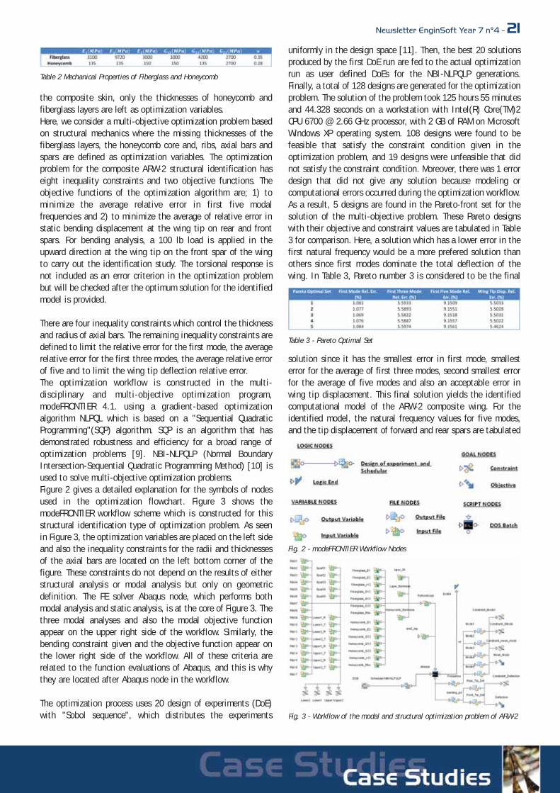
uniformly in the design space [11]. Then, the best 20 solutionsproduced by the first DoE run are fed to the actual optimizationrun as user defined DoEs for the NBI-NLPQLP generations.Finally, a total of 128 designs are generated for the optimizationproblem. The solution of the problem took 125 hours 55 minutesand 44.328 seconds on a workstation with Intel(R) Core(TM)2CPU 6700 @ 2.66 GHz processor, with 2 GB of RAM on MicrosoftWindows XP operating system. 108 designs were found to befeasible that satisfy the constraint condition given in theoptimization problem, and 19 designs were unfeasible that didnot satisfy the constraint condition. Moreover, there was 1 errordesign that did not give any solution because modeling orcomputational errors occurred during the optimization workflow.As a result, 5 designs are found in the Pareto-front set for thesolution of the multi-objective problem. These Pareto designswith their objective and constraint values are tabulated in Table3 for comparison. Here, a solution which has a lower error in thefirst natural frequency would be a more prefered solution thanothers since first modes dominate the total deflection of thewing. In Table 3, Pareto number 3 is considered to be the final
solution since it has the smallest error in first mode, smallesterror for the average of first three modes, second smallest errorfor the average of five modes and also an acceptable error inwing tip displacement. This final solution yields the identifiedcomputational model of the ARW-2 composite wing. For theidentified model, the natural frequency values for five modes,and the tip displacement of forward and rear spars are tabulated
Table 2 Mechanical Properties of Fiberglass and Honeycomb
Fig. 2 - modeFRONTIER Workflow Nodes
Fig. 3 - Workflow of the modal and structural optimization problem of ARW-2
Table 3 - Pareto Optimal Set

22 - Newsletter EnginSoft Year 7 n°4
in Table 4 to compare the values with the experimental data ina detailed way.
The identified computational model is subjected to a twistingmoment created by a 1 lb load applied upward at the wing tipon the front spar and a 1 lb load applied in downward at thewing tip on the rear spar. Then, the twisting response of theidentified composite ARW-2 wing is obtained and validated withBhardwaj's study [5] as shown in Figures 4 and 5.This study aimed to identify a full composite model of a 3D ARW-2 wing structure that can be used in validation studies ofaeroelastic tools. Former studies assuming isotropic skin werepublished, however a 3D composite skin approach was notreported in the literature to the best of author's knowledge. Inthis paper, this model is identified by utilization of multi-objective optimization techniques in an inverse engineeringapproach where the unknown thickness parameters and materialproperties were used as optimization variables while trying tominimize the error of the structural responses in modalfrequencies and bending displacements. Also, the twistingresponse of the identified computational model is comparedwith the experimental and former computational data. The nextstep of this study will be to validate the aeroelastic response ofthe identified composite model with experimental data and evenimprove the model by taking into account the fluid-structureinteraction for specified flow conditions.
References[1] M.C. Sandford, D. A. Siedel, C. V. Eckstorm and C.V. Spain. In
Geometrical and Structural Properties of an AeroelasticResearch Wing (ARW-2). NASA Technical Memorandum 4110,1989.
[2] M.C. Sandford, D. A. Siedel, and C. V. Eckstorm. In SteadyPressure Measurements on an Aeroelastic Research Wing(ARW-2). NASA Technical Memorandum 109046, 1994.
[3] D. A. Siedel, M.C. Sandford, and C. V. Eckstorm. In Measuredunsteady transonic aerodynamic characteristics of an elasticsupercritical wing. Journal of Aircraft, 24 (4):225-230, 1987.
[4] D. E. Cohen. In Trim Angle of Attack of Flexible Wings UsingNon-Linear Aerodynamics. PhD thesis, Virginia PolytechnicInstitute and State University, USA, 1998.
[5] M. K. Bhardwaj. In A CFD/CSD Interaction Methodology forAircraft Wings. PhD thesis, Virginia Polytechnic Institute andState University, USA, 1997.
[6] M. Farhangnia, G. Guruswamy, and S. Biringen. In Transonic-buffet associated aeroelasticity of a supercritical wing. 34thAerospace Science Meeting and Exhibit,January 15-18 1996,Reno, NV. AIAA, 1996.13
[7] M. Nikbay and A. Aysan. In Identification of Structural andAeroelastic Properties of a Computational ARW-2 Wing Model
For Aeroelastic Optimization Applications. IFASD-2009,International Forum on Aeroelasticity and StructuralDynamics, Seattle, WA, June 21-25 2009.
[8] P. K. Mallick. Fiber-Reinforced Composites. Materials,Manufacturing, and Design Second Edition, Revised andExpanded, New York, USA, 1993.
[9] K. Schittkowski and C. Zillober, and R. Zotemantel. InNumerical Comparison on Nonlinear Programming Algorithmsfor Structural Optimization. Struc. Optim., 7: 1--28, 1994
[10] I. Das and J.E. Dennis. In Normal-Boundary Intersection: ANew Method for Generating the Pareto Surface in NonlinearMulticriteria Optimization Problems. SIAM Journal onOptimization, 8:631--657, 1998
[11] modeFRONTIER V4 Version Documentation. Esteco.
For more information, please contact: Melike NIKBAY, Ph.D. - Assistant ProfessorIstanbul Technical University - Faculty of Aeronautics andAstronautics. Department of Astronautical Engineering, AirSpace Medium and Systems Division. [email protected]
Nikbay MelikeIstanbul Technical University, Faculty of Aeronautics andAstronautics, Dept. of Astronautical Engineering - Turkey
Gür FırataIstanbul Technical University, Faculty of Aeronautics andAstronautics, Aeronautical and Astronautical Engineering
Program - [email protected]
Tanır EmrebIstanbul Technical University, Faculty of Aeronautics andAstronautics, Aeronautical and Astronautical Engineering
Program - [email protected]
Table 4 - Relative Errors Between the Computational and the ExperimentalData
Fig. 4 - Displacement of the Front Spar of ARW-2 Subjected to a TwistingLoad
Fig. 5 - Displacement of the Rear Spar of ARW-2 Subjected to a TwistingLoad
(a) Refence Study [5] (b) Current Study
(a) Study [5] (b) Current Study

Newsletter EnginSoft Year 7 n°4 - 23
In questo articolo vengono presentate le principali no-vità di ANSYS CFD 13. Sotto questo nome vengono in-clusi i due principali solutori fluidodinamici ANSYS CFXe ANSYS FLUENT oltre ad una serie di strumenti verti-calizzati per lo studio di turbomacchine (BladeModelere TurboGrid) e di raffreddamento di componenti elet-tronici (Icepak).Nella versione 13.0 viene rafforzata la struttura diANSYS Workbench, l’ambiente di lavoro parametrico checostituisce il punto di integrazione di tutti i software ANSYSe permette la definizione di un unico processo di analisi perla simulazione di diversi aspetti fisici di uno stesso sistema.Dalla versione 13.0, oltre all’interazione fluido-struttura, èpossibile studiare l’interazione tra aspetti elettromagnetici,fluidodinamici e strutturali in un unico processo di simulazio-ne.Nell’articolo vengono inoltre spiegate le principali novità deidue solutori CFD e le linee di sviluppo che si basano su treprincipi fondamentali: robustezza, efficienza ed accuratezzadel calcolo.
ANSYS CFD in WorkbenchLa struttura di ANSYS CFD rimane immutata rispetto alla ver-sione 12 ed è completamente integrata in ANSYS Workbench(Figura 1 e Figura 2).
Gli strumenti di interfaccia con i CAD, il modellatore geome-trico ed ANSYS Meshing consentono di importare o costruireil modello in maniera parametrica e di generare una griglia dicalcolo automatica utilizzando diversi metodi di mesh.Il set-up dell’analisi e la soluzione vengono eseguite separa-tamente per i due codici ANSYS CFX e ANSYS FLUENT, mentreil post-processamento torna ad essere eseguito in un am-biente unico CFD-Post.
Le principali novità di ANSYS Workbench riguardano:• L’estensione nell’utilizzo dei parametri (Figura 3). Un
maggior numero di grandezze possono essere definite
come parametri ed utilizzate in Workbench per lanciaresequenze di analisi in batch. Per esempio anche le dimen-sioni della mesh possono essere trattate in maniera para-metrica ed è stato aumentato il numero di parametri inse-ribili nel set-up di Fluent;
• Una gestione più rapida del passaggio di carichi da unasoluzione CFD ad un modello termico e strutturale. Èinfatti possibile dalla versione 13 passare un campo ditemperatura su un intero corpo anziché sulle sole super-fici ed è stato reso più rapido il processo di interpolazio-ne dei dati (Figura 4);
• Il passaggio di informazioni tra il codice elettromagneti-co Maxwell e un modello fluidodinamico (Figura 5);
• La possibilità di lanciare sequenze di analisi in batchmediante Remote Solver Manager. Questo permette di lan-ciare diverse analisi in simultanea sfruttando tutte lemacchine disponibili in rete tramite un sistema a code.
• L’inclusione di MS Excel in un processo di analisi e la suainterazione con gli altri software.
ANSYS CFD 13.0
Fig. 1 - ANSYS Workbench, modellazione parametrica ed integrazione didiverse discipline
Fig. 2 - struttura di ANSYS CFD 13
Fig. 3 - definizione di una sequenza di analisi parametrica e lancio batch
Fig. 4 - interazione fluido-struttura, passaggio di carichi termici e di pressione
24 - Newsletter EnginSoft Year 7 n°4
DesignModeler e ANSYS Meshing: strumenti geometrici e di meshUn ulteriore passo avanti è stato fatto sia nella modellazio-ne geometrica sia nei metodi di mesh unificati. È importan-te ricordare che gli strumenti DesignModeler e ANSYSMeshing permettono di creare geometrie e mesh di calcoloper tutti i software ANSYS con notevoli vantaggi nella condi-visione di geometrie tra discipline diverse.Un unico modello geometrico e lo stesso ambiente di meshpossono essere messi in condivisione tra CFD, FEM ed elettro-magnetismo con notevole risparmio di lavoro e tempo.DesignModeler garantisce l’import da CAD con lettura dei pa-rametri e con la versione 13 ha visto l’introduzione di stru-menti che consentono la pulizia e la generazione delle geo-metrie in modo più rapido e flessibile.Per quanto riguarda i metodi di mesh per la fluidodinamica losviluppo è andato nella direzione di:• Aumento di efficienza nella generazione con riduzione
dell’occupazione di memoria e conseguente aumento del-la massima dimensione di mesh;
• Generazione di mesh in parallelo per l’abbattimento deitempi di calcolo;
• Introduzione di metodi di mesh derivati da ICEM-CFD,Gambit e T-grid per rendere disponibili tecniche avanzatedi mesh;
• Miglioramento della diagnostica e del controllo qualità;• Interoperabilità: diversi metodi di mesh possono essere
impiegati su uno stesso modello in diverse parti geome-triche. Questo porta maggiore flessibilità per domini com-plessi;
• Meshing Body-by-Body: l’aggiornamento o la modifica dimesh viene gestita separatamente per i corpi diversi ed èquindi più rapida per le geometrie complesse.
ANSYS CFX e ANSYS Fluent: i solutori fluidodinamiciNello sviluppo della versione 13 è stata data continuità allelinee di sviluppo della versione 12 seguendo le richieste deiclienti e le applicazioni dei principali settori industriali. Ipunti fondamentali di sviluppo sono i seguenti e sono comu-ni sia ad ANSYS CFX che ad ANSYS FLUENT:• Robustezza e accuratezza del solutore, efficienza del cal-
colo parallelo: in Fluent è stato introdotto un nuovo sche-ma numerico (pseudo-transient) che permette di ridurre
di un ordine di grandezza il numero di iterazioni necessa-rie per convergere. È stato inoltre reso più efficiente ilcalcolo parallelo su processori multi-core ed è stato ridot-to il tempo necessario per le operazioni di Input/Outputcon sensibili incrementi di velocità di calcolo;
• Simulazione di motori a combustione interna: sia inFluent che in CFX continua lo sviluppo delle metodologiedi simulazione motore. In Fluent sono disponibili nuovemodalità di gestione delle mesh deformabili, mentre inCFX sono state sviluppate delle interfacce che guidanol’utente nella definizione della movimentazione di valvo-le e pistone, nella gestione della mesh deformabile e del-le condizioni di flusso nella varie fasi-motore. Le stesseinterfacce consentono anche di far comunicare CFX consoftware mono-dimensionali di comune impiego in ambi-to motoristico;
• Modelli di trasporto di particelle: questi modelli trovanoimpiego nella simulazione dei processi di iniezione dicombustibile liquido e solido e sono utilizzati nell’indu-stria chimica e di processo e in quella dei motori auto eaeronautici. L’utilizzo della CFD in questi settori ha loscopo di ridurre i consumi di combustibile e le emissioniinquinanti. In CFX il tempo di calcolo di traiettorie è sta-to ridotto di 3-4 volte con miglioramenti del 30-40% suitempi dell’intera simulazione. Sono stati introdotti inoltrenuovi materiali e la possibilità di definire miscele disostanze, rendendo quindi più realistica la composizionedei combustibili simulati. Infine è stata migliorata larobustezza del calcolo ed è quindi possibile simulare cari-chi più elevati di particelle;
• Modelli multifase euleriani: oltre ai metodi più precisi perla risoluzione delle interfacce tra le fasi, sono stati intro-dotti modelli di ebollizione e condensazione a parete e diwall film;
• Modelli di combustione: anche in questo ambito sono sta-ti introdotti nuovi modelli per la simulazione di motori acombustione interna (G-equation e spark ignitionmodels);
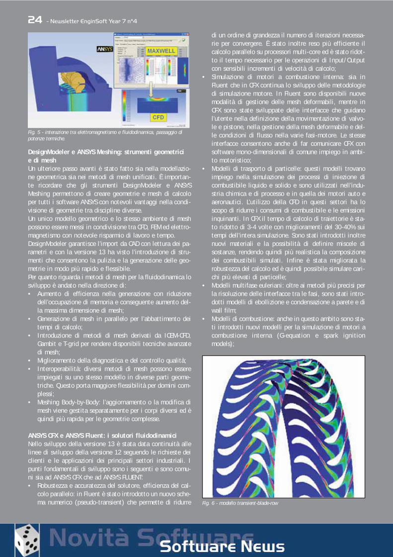
Fig. 5 - interazione tra elettromagnetismo e fluidodinamica, passaggio dipotenze termiche.
Fig. 6 - modello transient-blade-row
Newsletter EnginSoft Year 7 n°4 - 25
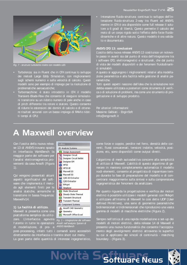
• Turbolenza: sia in Fluent che in CFX continua lo sviluppodei metodi Large Eddy Simulation, con miglioramentisugli schemi numerici e sulla velocità di calcolo. Questimodelli sono per esempio di impiego per la risoluzione diproblematiche aeroacustiche;
• Turbomacchine: è stato introdotto in CFX il modelloTransient-Blade-Row che consente di eseguire simulazio-ni transitorie su un ridotto numero di pale anche in casodi pitch differente tra rotore e statore. Questo consentedi ridurre le estensioni dei domini di calcolo e di ottene-re risultati accurati con un basso impiego di RAM e ridot-ti tempi di CPU;
• Interazione fluido-struttura: continua lo sviluppo dell’in-terazione fluido-struttura 2-way tra Fluent ed ANSYS,mentre in CFX è ora disponibile come full release il solu-tore a 6 gradi di libertà. Questo permette il calcolo delmoto di un corpo rigido sotto l’effetto delle forze fluido-dinamiche e di altre natura. Questo modello è ora valida-to e documentato.
ANSYS CFD 13: conclusioniL’uscita della nuova release ANSYS 13 costituisce un notevo-le passo in avanti sia dal punto di vista dell’integrazione trai software CFD, elettromagnetici e strutturali, che dal puntodi vista dei modelli disponibili e dei fenomeni fluidodinami-ci simulabili.A questo si aggiungono i miglioramenti relativi alla modella-zione parametrica e alla facilità nella gestione di analisi pa-rametriche.Tutti questi aspetti nascono dall’idea che la simulazione nondebba essere utilizzata a posteriori come strumento di verifi-ca o di soluzione di problemi, ma come uno strumento di pro-gettazione e di sviluppo prodotto.
Per ulteriori informazioni:Massimo Galbiati - [email protected]
Fig. 7 - strutture turbolente risolte con modello LES
A Maxwell overviewCon l’uscita della nuova relea-se 13 di ANSYS trovano spazioin interfaccia WorkBench lamaggior parte dei software perl’analisi elettromagnetica pro-venienti da casa Ansoft (Figura1).
Qui vengono presentati alcuniaspetti significativi del soft-ware che implementa il meto-do agli elementi finiti per leanalisi statiche, armoniche etransitorie in bassa frequenza:Maxwellv14.
1) La facilità di utilizzo.Maxwell si presenta come unapiattaforma semplice da utiliz-zare. L’interfaccia agevolal’utente in tutte le operazionidi modellazione, di pre- epost-processing, infatti tutti i comandi sono accessibilidirettamente da interfaccia o tramite short cut menu.La gran parte delle quantità di interesse ingegneristico,
come forze e coppie, perdite nel ferro, densità delle cor-renti, flussi concatenati, tensioni indotte, velocità, posi-zione, etc, sono disponibili come output diretti.
L’algoritmo di mesh autoadattiva concorre alla semplicitàdi utilizzo di Maxwell. L’abilità di questo algoritmo di ge-nerare in maniera completamente automatica il modellonodi-elementi, consente al progettista di risparmiare tem-po durante la fase di preparazione del modello e di con-centrarsi maggiormente sulla sintesi e sulla comprensioneingegneristica dei fenomeni da analizzare.
Per quanto riguarda la progettazione e verifica dei motorielettrici è possibile utilizzare i modelli generati con RMxprto utilizzare all’interno di Maxwell le cosi dette UDP (Userdefined Primitives), una serie di geometrie parametrichebidimensionali e tridimensionali che riproducono una vastagamma di modelli di macchine elettriche (Figura 2).
Sempre nell’ottica di una rapida modellazione e set-up deimodelli di motori elettrici, dalla release 14 di Maxwell èpresente una nuova funzionalità che consente l’accoppia-mento degli avvolgimenti elettrici attraverso le superficisu cui si applicano dei vincoli di continuità - matchingboundary - (Figura 3).
Fig. 1 – integrazione dei softwareAnsoft nell’analysis System diANSYS WorkBench
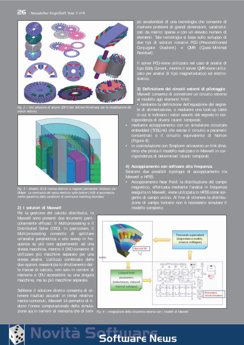
26 - Newsletter EnginSoft Year 7 n°4
2) I solutori di MaxwellPer la gestione del calcolo distribuito, inMaxwell sono presenti due strumenti parti-colarmente efficaci: il Multiprocessing e ilDistributed Solve (DSO). In particolare, ilMultiprocessing consente di splittareun’analisi parametrica o uno sweep in fre-quenza su più core appartenenti ad unastessa macchina, mentre il DSO consente diutilizzare più macchine separate per unastessa analisi. L’utilizzo combinato delledue opzioni massimizza lo sfruttamento del-le risorse di calcolo, non solo in termini dimemoria e CPU accessibile su una singolamacchina, ma su più macchine separate.
Sebbene il solutore diretto consenta di ot-tenere risultati accurati in tempi relativa-mente contenuti, Maxwell 14 permette di ri-durre l’onere computazionale della simula-zione sia in termini di memoria che di tem-
po avvalendosi di una tecnologia che consente dirisolvere problemi di grandi dimensioni, caratteriz-zati da matrici sparse e con un elevato numero dielementi. Tale tecnologia si basa sullo sviluppo didue tipi di solutori iterativi PCG (PreconditionedConjugate Gradient) e QMR (Quasi-MinimalResidual).
Il solver PCG viene utilizzato nel caso di analisi ditipo Eddy Current, mentre il solver QMR viene utiliz-zato per analisi di tipo magnetostatico ed elettro-statico.
3) Definizione dei circuiti esterni di pilotaggioMaxwell consente di connettere un circuito esternoal modello agli elementi finiti:• mediante la definizione dell’equazione del segna-le di alimentazione, o mediante una look-up tablein cui si indicano i valori assunti dal segnale in cor-
rispondenza di diversi istanti temporali;• mediante accoppiamento con un simulatore circuitale
embedded (TDSLink) che estrae il circuito a parametriconcentrati o il circuito equivalente di Norton (Figura 4);
• in cosimulazione con Simplorer attraverso un link dina-mico che pilota il modello realizzato in Maxwell in cor-rispondenza di determinati istanti temporali.
4) Accoppiamento con software alta frequenzaEsistono due possibili tipologie di accoppiamento traMaxwell e HFSS:• Accoppiamento Near Field: la distribuzione del campo
magnetico, effettuata mediante l’analisi in frequenzaeseguita in Maxwell, viene utilizzata in HFSS come sor-gente di campo vicino. Al fine di ottenere la distribu-zione di campo lontano non è necessario simulare ilmodello completo;
Fig. 2 – Una selezione di alcune UDP (User defined Primitives) per la modellazione deimotori elettrici.
Fig. 3 – Modello 3D di motore elettrico a magneti permanenti ottenuto conRMxprt. La continuità del carico elettrico sulle bobine (A-B) è automatica-mente garantita dalle condizioni di continuità matching boundary
Fig. 4 – integrazione della circuiteria esterna con i modelli di Maxwell.

• Quando in HFSS è necessario modellare materiali ferro-magnetici che presentano una magnetizzazione nonuniforme, questa può essere valutata in Maxwellmediante un’analisi statica e successivamente esporta-ta verso il modello in HFSS.
5) Calcolo della demagnetizzazione dei magneti per-manenti.Maxwell consente di valutare la demagnetizzazione deimagneti permanenti sottoposti ad un campo magneticoche si oppone a quello proprio del magnete, come adesempio quello generato da una bobina percorsa da cor-rente.
Il calcolo può essere effettuato sia mediante un’analisimagnetostatica che transient.
La procedura utilizza 2 analisi successive:Nella prima analisi viene considerato un modello nel qua-le vi sia il magnete permanente e la sorgente smagnetiz-zante. In tal modo per ciascun elemento del magnete sidetermina il punto di lavoro sulla curva BH.
La seconda analisi importa la soluzione precedente, ed at-tribuisce ad ogni elemento del magnete permanente unnuovo tratto di curva BH (recoil curve) ottenuto con i da-ti resi disponibili dall’analisi precedente.
Dalla release Maxwell 14 la procedura descritta può esse-re implementata considerando una curva di demagnetizza-zione BH estesa al terzo quadrante. La Figura 5 sintetizzaquanto finora descritto.
6) Calcolo delle perdite nel ferro per gli acciai elettri-ci:Le perdite nel ferro si compongono di tre termini come in-dicato nell’equazione seguente:
in cui compaiono le perdite per isteresi, le perdite dovutealle Eddy Current e le perdite addizionali [1].
I valori dei coefficienti presenti nell’equazione (Kh, Kc e Ke)sono difficilmente reperibili. Maxwell calcola tali coeffi-cienti a partire dalle curve di perdita dei lamierini magne-tici (note da DataSheet) attraverso una procedura diCurve-Fitting. Le curve di perdita possono essere inseritein corrispondenza di una o più frequenze.
La Figura 6 mostra le perdite nel pacco magnetico di untrasformatore implementando la procedura illustrata.
7) Insulating Shell BoundaryLe Insulating Shell Boundary sono condizioni al contornodi particolare interesse ingegneristico che Maxwell con-sente di definire. Tali condizioni sono generalmente utiliz-zate per modellare fogli di materiale isolante caratterizza-ti da spessori infinitesimi, o crack sottili all’interno diconduttori. In Figura 7 viene mostrato come un crack mo-dellato con tale boundary possa modificare il percorso del-le correnti indotte.
8) Curve BH per materiali anisotropi e laminatiMaxwell permette di definire la composizione di un mate-riale non lineare come laminato, o di assegnargli proprie-tà anisotrope.
I lamierini magnetici sono ampiamente utilizzati per la ri-duzione delle perdite dovute alle correnti parassite.
Newsletter EnginSoft Year 7 n°4 - 27
Fig. 6 – Perdite nel pacco magnetico di un trasformatore elettrico (a), evoluzione delle perdite nel tempo (b).
Fig. 5 – Curva di demagnetizzazione estesa al terzo quadrante.
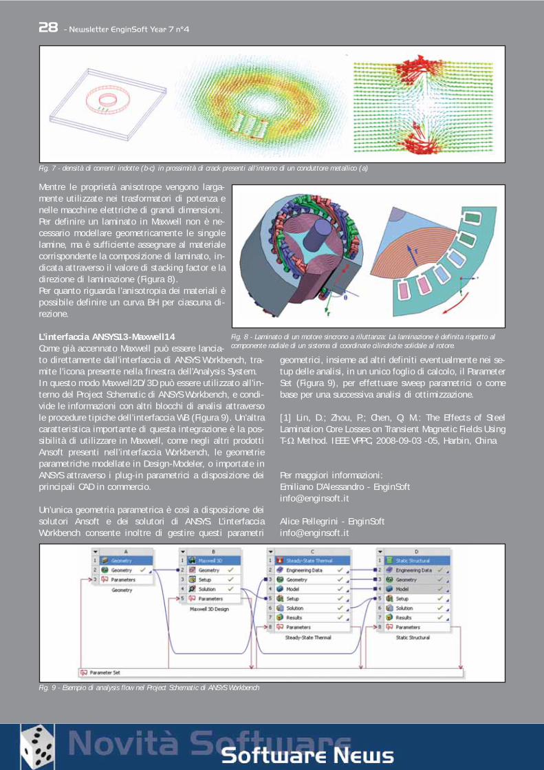
28 - Newsletter EnginSoft Year 7 n°4
Mentre le proprietà anisotrope vengono larga-mente utilizzate nei trasformatori di potenza enelle macchine elettriche di grandi dimensioni. Per definire un laminato in Maxwell non è ne-cessario modellare geometricamente le singolelamine, ma è sufficiente assegnare al materialecorrispondente la composizione di laminato, in-dicata attraverso il valore di stacking factor e ladirezione di laminazione (Figura 8).Per quanto riguarda l’anisotropia dei materiali èpossibile definire un curva BH per ciascuna di-rezione.
L’interfaccia ANSYS13-Maxwell14Come già accennato Maxwell può essere lancia-to direttamente dall’interfaccia di ANSYS Workbench, tra-mite l’icona presente nella finestra dell’Analysis System.In questo modo Maxwell2D/3D può essere utilizzato all’in-terno del Project Schematic di ANSYS Workbench, e condi-vide le informazioni con altri blocchi di analisi attraversole procedure tipiche dell’interfaccia WB (Figura 9). Un'altracaratteristica importante di questa integrazione è la pos-sibilità di utilizzare in Maxwell, come negli altri prodottiAnsoft presenti nell’interfaccia Workbench, le geometrieparametriche modellate in Design-Modeler, o importate inANSYS attraverso i plug-in parametrici a disposizione deiprincipali CAD in commercio.
Un’unica geometria parametrica è così a disposizione deisolutori Ansoft e dei solutori di ANSYS. L’interfacciaWorkbench consente inoltre di gestire questi parametri
geometrici, insieme ad altri definiti eventualmente nei se-tup delle analisi, in un unico foglio di calcolo, il ParameterSet (Figura 9), per effettuare sweep parametrici o comebase per una successiva analisi di ottimizzazione.
[1] Lin, D.; Zhou, P.; Chen, Q. M.: The Effects of SteelLamination Core Losses on Transient Magnetic Fields UsingT-Ω Method. IEEE VPPC, 2008-09-03 -05, Harbin, China
Per maggiori informazioni:Emiliano D’Alessandro - [email protected]
Alice Pellegrini - [email protected]
Fig. 7 - densità di correnti indotte (b-c) in prossimità di crack presenti all’interno di un conduttore metallico (a)
Fig. 8 - Laminato di un motore sincrono a riluttanza: La laminazione è definita rispetto alcomponente radiale di un sistema di coordinate cilindriche solidale al rotore.
Fig. 9 - Esempio di analysis flow nel Project Schematic di ANSYS Workbench

Newsletter EnginSoft Year 7 n°4 - 29
Novità ANSYS Mechanical versione 13 La nuova release ANSYS 13.0 è caratterizzata da diversenuove ed avanzate funzionalità finalizzate a rendere piùveloce, più semplice e più economico il raggiungimentodei risultati, controllando contemporaneamente l’accura-tezza del risultato finale della simulazione. Le nuove funzionalità si riferiscono alle seguenti tre areedi applicazione:1. Maggiore precisione e fedeltà: la progettazione multi-
disciplinare è uno degli obiettivi prin-cipali della versione di ANSYS 13.0,finalizzati a rispettare le esigenzeprogettuali espresse dagli utilizzatorie di rispecchiare in maniera semprepiù accurata la realtà e la sua evolu-zione nel tempo.
2. Maggiore produttività: ANSYS 13.0comprende una serie di tools, chehanno l’obiettivo di ridurre al minimoi tempi di gestione, in favore dellafase di progettazione.
3. Maggiore potenza di calcolo: peralcune simulazioni di ingegneria,ANSYS 13.0 è in grado di fornire ridu-zioni di velocità, nei tempi di simula-zione, anche da 5 a 10 volte maggio-re delle versioni software precedenti.
Di conseguenza anche simulazioni multifisiche molto com-plesse possono essere compiute in modo più rapido ed ef-ficiente, accelerando lo sviluppo dei prodotti e la fase diprogettazione.Un aspetto centrale che va ad inserirsi all’interno di que-sti aspetti di multidisciplinarietà è l’”External DataMapper”.
In molti team di progettazione mec-canica, più ingegneri, di disciplinediverse, si trovano a collaborare aduno stesso progetto con l’utilizzo distrumenti differenti. Per esempio in-gegneri che si occupano di analisifluidodinamiche (FLUENT o CFX) de-vono scambiare dati e risultati, su unmedesimo progetto, con coloro che sioccupano di analisi strutturali (peresempio la necessità di fornire tem-perature o pressioni provenienti dacalcolo fluidodinamico, ad ingegneriche si occupano di un successivo cal-colo strutturale).Come parte dell’impegno per la simu-lazione multifisica, ANSYS ha intro-
dotto vari processi automatizzati per il trasferimento deidati tra differenti fisiche di progetto:• da CFD a Strutturali;• da CFD a Termiche;• da Termiche a Strutturali;• da LF Emag a Strutturali;• da HF Emag a Termiche.
Con ANSYS 13.0, tramite l’”ExternalData Mapper” (Figura 1), c’è la possi-bilità di importare i dati sotto forma diun file di testo che definisce una nu-vola di punti con la corrispondentegrandezza da rimappare (Temperatura,pressione…). Il mapping dei datiesterni consente agli utenti di diversigruppi (come gli utenti CFD e struttu-rali) lo scambio di dati relativi al mo-dello in modo molto semplice ed im-mediato; prevedendo la possibilità diimportare la temperatura corporea, lapressione superficiale, il coefficientedi scambio termico… L'utente può de-finire, da interfaccia (Figura 2), le uni-tà per i dati da importare e allineare idati con la geometria corrente.
Per quanto riguarda l’analisi esplicita, sempre nell’otticadella multidisciplinarietà, ANSYS ha proseguito il cammi-no verso la completa integrazione di AUTODYN all’internodella piattaforma ANSYS Workbench.Nell’ambito delle simulazioni esplicite, poiché i liquidi ogas, presenti nel nostro modello (per esempio liquidi con-tenuti in un recipiente) possono influenzare drasticamen-
Fig. 1 - Link per l’importazione dei dati esterniimportati
Fig. 2 - Inserimento delle unità di misura per i dati

30 - Newsletter EnginSoft Year 7 n°4
te il comportamento generale dell’intero assieme, ANSYSha introdotto una nuova funzionalità chiamata "accoppia-mento di Eulero-Lagrange" all'interno dell’Explicit ANSYSSolver della release 13.0.
Questa caratteristica, prima disponibile solo in interfacciaAUTODYN, è disponibile per l'ambiente Workbench (Figura3), rendendola così di facile utilizzo per tutticoloro che già sfruttavano la piattaformaANSYS WB per altre applicazioni. Di conse-guenza, per gli utenti di ANSYS MechanicalWorkBench, la definizione del modello è moltosimile a una simulazione implicita con corpi ri-gidi e flessibili: sarà necessario solamente se-lezionare l’opzione euleriana rispetto a quellalagrangiana, che, nella precedente release eral’unica disponibile.
Le applicazioni tipiche di questa tecnica sono:• Impatto o caduta di fluido (corpo riempito
o parzialmente riempito, bottiglie,contenitori…);
• Navi;• Esplosivo;• Formatura e idroformatura;• Impatti ad alta velocità, dove la deformazione del
bersaglio e /o di un proiettile è estrema, (e quindi èpreferibile scegliere l’accoppiamento Euleriano-Lagrangiano);
• In Ambito Aerospaziale (ammaraggio aereo…).
Un aspetto fondamentale dell’inserimento di AUTODYN al-l’interno della piattaforma Workbench, è la disponibilitàdell’intera libreria di materiali espliciti che erano presentisolo in AUTODYN, e il loro conseguente facile utilizzo tra-
mite l’Engineering Data con cui gli utenti diANSYS WB hanno già familiarità dalle versioniprecedenti (Figura 4).
Un ulteriore aspetto sul quale si è concentrataANSYS nella nuova release è l’impegno nel forni-re soluzioni ad alte prestazioni, monitorandol'evoluzione hardware al fine di trarne vantaggioper i processi di simulazione. L’obiettivo è di ri-durre i tempi di soluzione per gli utenti in mododa essere un leader del settore in questa tecno-logia, non solo come soluzioni ottenute ma an-che come tempistica. L'idea generale sta nell’uti-lizzo delle GPU, scaricando i pesanti algoritmi dicalcoli complessi su più schede di GPU in gradodi eseguire calcoli general-purpose con precisio-ne doppia.
Attualmente, sfruttando queste nuove tecnolo-gie, ci si può aspettare un incremento di veloci-tà dei tempi di risoluzione pari a 2-3 volte, nel
caso di una simulazione con 4 core della serie Nehalem5.500.
Per maggiori informazioni:Daniele Calsolaro - [email protected]
Fig. 3 - Accoppiamento Eulero-Lagrange
Fig. 4 - Libreria materiali espliciti (TNT, PBX…)
Fig. 5 - Confronto dei tempi di risoluzione con l’uso delle GPU

Newsletter EnginSoft Year 7 n°4 - 31
We are pleased to announcethat version 4.3.0 ofmodeFRONTIER has been
released. modeFRONTIER 4.3.0 includes significant new featuresand several enhancements to the existing components.
Schedulers and Optimizers New Features and Improvements• NSGA-II was entirely re-designed to support unordered
discrete variables for mixed-integer problems. New schemeshave been added:
o Controlled Elitism to increase uniformity distribution ofPareto front.
o Variable Population Size for higher accuracy ofapproximated Pareto front.
o Steady State Evolution (MFGA): steady state evolutionwith an adaptive elitism procedure for an efficientparallelization scheme.
• The External Schedulers Bridge lets the users integrate user-defined optimizers with modeFRONTIER to enhanceflexibility and efficiency for specific optimization problems.A runtime library to exchange data between modeFRONTIER
and third-party software tools (including MATLAB, Scilab andOctave) is provided, thus custom optimization algorithmscan be coupled with modeFRONTIER.
• Parallel RSM training using multi-thread technology in theFSIMPLEX and FMOGA-II algorithms.
• Enhancements for the MOSA algorithm, which include: o Support of unordered discrete variables. o Steady-state evolution option.
• Support of unordered discretevariables for the EvolutionStrategy algorithm.
RSM algorithms Improvements• Evolutionary Design RSM can
now perform parallel RSMtraining using multi-threadtechnology in order to exploitcomputational resourcesavailable.
The Design Space New Features• New Correlation Matrix chart which is now provided with an
interactive threshold filter for selective visualization ofcorrelation matrix. In addition to the already existingPearson coefficient, Spearman, Partial Correlation and PartialRanking Correlation coefficients have been added to the list.
The RSM Multiple Function Plot for comparative display ofmultiple RSM functions created and interactive moving sliders tochange input values and update the related RSM function. The Design Space Template which allows Design Spacevisualization charts to be saved to an XML Template file for laterreuse in different projects.
The Workflow New Features• The Grid System powered by GridGain system which enables
modeFRONTIER for grid computing. This system letsmodeFRONTIER submit Workflow design evaluation jobsacross a local network, wait for the execution and retrieve
modeFRONTIER 4.3.0 is now available
Fig. 1 - The new NSGA-II configuration panel
Fig. 2 - External SchedulersBridge
Fig. 3 - New Correlation Matrix chart

32 - Newsletter EnginSoft Year 7 n°4
the results. The Grid System is available in beta version forthe UGS-NX, LabVIEW, ANSYS Workbench and SimulationXnodes only.
The new ANSYS Workbench Direct Integration Node whichincludes the following features: • Support of ANSYS Workbench v12.1. • Handling of Input/Output Parameters defined in the
Workbench Parameter Set. • Pre-processing macro functionalities available to detect
geometry failure, check mesh quality or similar. • Post-processing macro functionalities available for advanced
assessment of results. • Support GridGain system for distributed computing.
The METAPost Direct Integration Node to let METAPost usersextract FEA responses for the optimization problem, by readingthe following quantities: • Real Scalar History • Real Vector History (X,Y history curve) • Complex Vector History (Frequency, Magnitude and Phase) • The SimulationX Direct Integration Node for coupling with
the SimulationX software used for design, analysis, andoptimization of complex systems. The interface availableenables parsing of inputs/outputs parameters to/fromComponents and Connections, including scalar (e.g.component/connection parameters), vector (e.g. outputcurves) and matrix (e.g. Component Tables) data. TheSimulationX node supports the GridGain system fordistributed computing.
• The new JMAG Direct Integration Node which supports JMAGDesigner and handles input scalar parameters for the Studyavailable as well as scalar output parameters.
• The new Octave Direct Integration Node for coupling withthe Octave software tool.
• The SoC Node allows easy integration into themodeFRONTIER optimization workflow of any System-on-Chip simulator that follows the Multicube specifications. Theintegration node takes care of the design spaceintrospection, automatic workflow generation and simulatorinteraction.
• The LookUpTable (LUT) node which for a given set of inputsX=(X1,X2,...,Xn), and a reference sets of data (i.e. any tablein the Design Space) finds the nearest point to X, byreturning the array corresponding to the design of thedateset which best matches X. Consequently, combined useof the LUT node and SOM utility enables the users to use anySOM Table in the Workflow to find the BMU in order toclassify sets of data for each iteration of the schedulerselected.
• The Workflow Creation Wizard which allows the users toquickly and easily create basic Workflow patterns, includingInput/Output variables, vectors, application nodes and filenodes.
Fig. 4 - RSM Multiple Function Plot
Fig. 6 - The Grid Manager interface
Fig. 7 - The METAPost Interface
Fig. 5 - Design Space Template

Newsletter EnginSoft Year 7 n°4 - 33
• The Workflow Creation and Edit from Excel which nowsupports import/export of variable settings for vectorvariables.
• The Custom Workflow Library for selective view of theWorkflow nodes library.
ImprovementsMajor improvements of the existing features include: • Ambient conditions available as input and custom unit
selection in the Flowmaster node. • New license check option before the evaluation run starts for
the ANSA and GT-SUITE node. • PRT and ASM versioning control in the ProEngineer node. • Timeout option available in the application script nodes
For more information:Francesco Franchini - [email protected]
Fig. 8 - The Workflow Creation Wizard
Fig. 9 - The Custom Workflow Library
Corsi di Addestramento Software2011 - EnginSoft & modeFRONTIERNel contesto di un’applicazione ingegneristica (sviluppoprodotto, analisi numerica FEM/CFD tramite strumenti CAD-CAE, analisi di scenario, …), modeFRONTIER è in grado dideterminare come le diverse possibili soluzioni progettuali sicollochino e si differenzino una rispetto all’altra (in funzionedelle variabili monitorate), e quindi è in grado di ricercarequelle configurazioni che garantiscano il miglioramento delleprestazioni (obiettivi) del sistema investigato e/o ilconseguimento delle specifiche prefissate(obiettivi/vincoli). L’utente di turno (i.e. project engineer,process/product engineer, …) ha dunque la possibilità dicomprendere se la soluzione ottenuta è effettivamentequella di ottimo rispetto alle condizioni al contornoprestabilite oppure se è fattibile e/o conveniente ricercarneuna migliore.
modeFRONTIER: Corso Standard• Introduzione a modeFRONTIER;• Ambiente di pre-processing di modeFRONTIER e logica di
costruzione del workflow;• Applicazione degli strumenti fondamentali del workflow
di modeFRONTIER;• Metodologie DOE e descrizione delle tecniche DOE dispo-
nibili in modeFRONTIER;• Acquisizione dati, fondamenti di analisi statistiche e di
distribuzione con modeFRONTIER;• Introduzione alla teoria di base dell’ottimizzazione
(mono e multi-obiettivo), algoritmi e strategie di otti-mizzazione con modeFRONTIER;
• Post-processing dei dati per mezzo di strumenti dedicatialla analisi di problemi multi-obiettivo, analisi di sensi-tività, analisi statistica;
• Introduzione all’utilizzo delle tecniche RSM (ResponseSurface Methodologies) con modeFRONTIER;
• Cenni alla Robust Design Optimization conmodeFRONTIER.
modeFRONTIER: Corso Avanzato• Implementazione di workflow con logiche di ottimizza-
zione complesse con modeFRONTIER;• Algoritmi di ottimizzazione avanzati e loro benchmarking
con modeFRONTIER;• Analisi statistica avanzata ed analisi multi-variata di dati
con modeFRONTIER;• Self-Organizing Maps (SOM) e Clustering di dati in
modeFRONTIER;• tecniche RSM – teoria, pratica e loro combinazione con
l’ottimizzazione diretta in modeFRONTIER;• Multi Objective Robust Design Optimization (MORDO) con
modeFRONTIER – analisi di robustezza;• Multi Criteria Decision Making (MCDM) – supporto alle
decisioni per problemi multi-obiettivo.
www.enginsoft.it/corsi
34 - Newsletter EnginSoft Year 7 n°4
The following article presents an overview of the technicalcollaboration between EnginSoft and Key to Metals. The commonproject concerns the development of the KTM product for the“Extended Range” module and also the agreement for thecommercial distribution of the “Customized Solution” module,both at national and international level.
The KEY to METALS database is designed to help a broad rangeof engineering professionals in finding equivalent materialsworldwide, getting easy-to-use and accurate metalproperties, and navigating through internationalstandards. The KEY to METALS database includesmore than 4,000,000 property records for over160,000 metal alloys from all over the world, withthe “standard” dataset comprising of internationalcross-reference tables, composition, mechanicaland physical properties, heat treatment diagrams,advanced properties such as stress-strain curves,fatigues and more. The platform is available in 19 languages, onlineand as desktop software. Turn-key, easy to use andversatile, the KEY to METALS database is currentlybeing used in over 100 countries, in companiesranging from world leaders and Fortune 500Companies to the smallest Businesses, providingthe customer with time and money savings inconjunction with increased quality of engineeringand sourcing possibilities. For companies whose material properties information needs togo beyond the standard database and search engine, Key toMetals AG now offers tailor-made, customized solutions. Withflexible implementation, our solutions range from online Webservices to closed intranet applications to embedded OEMcomponents depending on the customer’s needs. Customized Keyto Metals solutions can be grouped into two categories: privatedatabases and material data export.
Private DatabasesThese solutions combine the complete information scope andfunctionality from the Key to Metals database, or a part thereofcombined with a private database containing the customer’sproprietary information. The information contained is highly dependent on the needs ofthe particular customer and may include:
Customized KEY toMETALS Solutionsfor MaterialsProperties
Questo articolo si fonda sul rapporto di collaborazione di naturatecnica tra EnginSoft e Key to Metals per lo sviluppo del prodottoKTM per il modulo “Extended Range”, nonché sull’accordo didistribuzione commerciale, sia nazionale che internazionale, per ilmodulo “Customized Solutions” particolarmente interessante peri Key Accounts di EnginSoft in Italia e nel mondo"
Il Database KEY to METALS è stato sviluppato per supportare unavasta gamma di Progettisti strutturali nella ricerca di proprietà
chimico-fisico-meccaniche di leghe metalliche mondiali unita-mente alle loro corrispondenze incrociate. KEY to METALS inclu-de più di 4.000.000 singoli dati relativi a più di 160.000 leghee contiene anche ulteriori utili informazioni quali diagrammi ditrattamento termico, curve stress-strain, fatica e altro ancora.
La piattaforma è disponibile in 19 lingue che utilizzano caratte-ri originali, e consente accessi on-line o da desktop. Il databa-se è attualmente utilizzato in oltre 100 paesi, in Aziende chevanno dai leader mondiali compresi nella lista Fortune dei“major 500” fino a Imprese medio-piccole anche sotto i 10dipendenti, fornendo agli Utenti un notevole risparmio di tem-po assieme a un seti dati per la progettazione difficilmente repe-ribile altrimenti.
Soluzionipersonalizzate diKey to Metals perproprietà di leghemetalliche
Fig. 1 - schema di database e soluzioni proprietarieFig. 1 - General schematics of private database and solution.

Newsletter EnginSoft Year 7 n°4 - 35
• Proprietary metals used in customer’s supply chain;• Cross-referencing customer’s proprietary designations to
other standard and proprietary designation;• Approved materials and cross-references/replacements for
sourcing and engineering;• Collection of grades used for material identification in
conjunction with a spectrometer;• Proprietary heat treatment and welding procedures and
details;• Advanced properties, dimensions, tolerances, various tables;• Full texts or abstracts of customer’s standards and internal
specifications;• Additional information regarding shapes, dimensions,
tolerances, etc.
The private database is then combined with a custom-madeapplication, which is then deployed to the customer’s internalusers and possibly to its partners and suppliers if required (Fig.1).
The main benefits are: • It’s a turn-key solution, which will save a lot of time and
money when compared to in-house solutions;• Highest quality product, supported by a wealth of experien-
ce in developing applications for the metal working industry;• Cost and price advantage owing to developers in Eastern
Europe; • Full support, ISO 9000 and ISO 27000 service level; • Enables a “quick victory” for the customer by deploying a
system which brings results instantly.
Material Data ExportKey to Metals AG provides a full materials property data exportfacility from the Database, giving the customer the freedom touse the exported data in their own information system, forEnterprise Resource Planning (ERP), Product Lifecycle
Per le aziende che necessitano di informazio-ni e strutture informatizzate basate su speci-fici motori di ricerca, Key to Metals offre del-le soluzioni “personalizzate”. Grazie ad unaimplementazione flessibile si offrono soluzio-ni che vanno da servizi web on-line ad appli-cazioni di tipo “chiuso” (intranet), fino adaccordi OEM basati sulle singole esigenze.Queste soluzioni possono essere raggruppatein 2 categorie: database proprietari ed espor-tazione di dati secondo determinati formati.
Database proprietariQueste soluzioni combinano la funzionalitàparziale o totale di Key to Metals con undatabase proprietario del Cliente. Le informa-zioni contenute dipendono sostanzialmentedalle esigenze dell’Utente e possono com-prendere:
• Metalli proprietari utilizzati nella supply chain del cliente;• Riferimenti incrociati tra le designazioni proprietarie del
cliente e quelle definite dalle Normative internazionali (rife-rimenti incrociati);
• Materiali alternativi per l’outsourcing e per la progettazione;• Raccolta specifica di Designazioni di leghe utilizzate per
identificare materiali tramite strumenti di analisi chimica;• Procedure di trattamento termico e saldatura proprietarie
con relativi dettagli;• Proprietà avanzate, dimensioni, tolleranze, tabelle,• Documentazione interna per capitolati, procedure etc.• Ulteriori informazioni in merito a forme, dimensioni, tolle-
ranze, ecc.
A richiesta, questo database “proprietario” può essere gestitocon una procedura sviluppata “su misura” per utilizzo all’internodell’Azienda o per una capillare distribuzione presso la reteesterna dei partners, clienti e fornitori (Figura 1).
I vantaggi principali sono:• È una soluzione “chiavi in mano”, che produce un sensibile
risparmio di tempo e denaro rispetto alle soluzioni “fatte incasa”;
• Massima qualità del prodotto, supportata da una notevoleesperienza nello sviluppo di applicazioni per l'industria dellalavorazione dei metalli;
• Costi molto competitivi che beneficiano della localizzazionenell’area Est-Europa;
• Supporto completo, qualità certificata ISO 9000 e ISO 27000per il livello dei servizi;
• Consente l’ottenimento di risultati in tempi estremamenterapidi con conseguente recupero dell’investimento iniziale.
Esportazione di dati sui materialiKey to Metals AG offre una totale fattibilità nella esportazionedei dati verso altri programmi, dando al cliente la completalibertà di processarli nel proprio sistema informatico rispettan-do specifiche esigenze quali quelle dettate da Enterprise
Fig. 2. - Esempio di selezione dei materiali, esportazione e aggiornamento Fig 2. - An example of material selection, exporting and updating workflow.

36 - Newsletter EnginSoft Year 7 n°4
Management (PLM) or any other application the customer deemsuseful. Besides the material data for thousands of materials thatcan be imported into the customer’s system, Key to Metals offersKEY to METALS Data Builder. This is a unique application thatcovers the complete workflow from the selection of the materialsof interest for the customer, exporting the data, to latermonitoring the updates done on the materials in the standardKEY to METALS database and importing the changes back intothe customer’s system (Fig 2). This way, besides having seamlessmaterial data, the customer has a database that is completelyup-to-date, and remains so via the push of a button (Fig 3).
The main benefits of the KEY to METALS material data export andData Builder are: • Tremendous savings in time and money comparing to “home-
made” databases, both in initial deployment andmaintenance;
• Easy-to-use wizard, with direct access to over 160,000 alloysfrom the database, possibility for data reviewing,recalculating, refining, multiple exporting file formats andworkflow support;
• Priority data updating plan and monthly updates via theWeb;
• Full support, ISO 9000 and ISO 27000 service level;• High quality of data, always up-to-date, which ultimately
brings “peace of mind” to the customer.
Victor Pozeit, Key to Metals AG, Zürich, Switzerland
Resource Planning (ERP), ProductLifecycle Management (PLM) o qual-siasi altra applicazione.Oltre ai dati per migliaia di materia-li che possono essere importati nelsistema del cliente, Key to Metalsoffre il cosiddetto “KEY to METALSdata Builder”. Questa è un'applica-zione unica che ricopre un flusso dilavoro completo, dalla selezione deimateriali di interesse per il cliente,all'esportazione dei dati, al control-lo periodico degli aggiornamenti persintonizzare il dati con le Normativein continua evoluzione (Fig. 2).
In questo modo, oltre a disporre didati sui materiali senza soluzione dicontinuità, il cliente dispone di undatabase che è completamente up-to-date, e rimane tale tramite lasemplice pressione di un tasto (Fig.3).
I principali vantaggi della esportazione di dati e del Key toMetals data Builder sono:• Un notevole risparmio di tempo e denaro rispetto a databa-
se “empirici” fatti in modo autonomo con notevoli problemidi manutenzione e aggiornamento;
• Facilità di uso, con accesso diretto a oltre 160.000 leghe daldatabase, con possibilità di verifica, di ricalcolo, di formatimultipli di esportazione files e supporto per il flusso opera-tivo;
• Piano di aggiornamento prioritario con aggiornamenti men-sili via web;
• Supporto completo con qualità certificata ISO 9000 e ISO27000 per livello di servizio;
• Alta qualità dei dati, sempre aggiornati, che forniscono lamassima “tranquillità” operativa per il cliente.
Victor Pozeit,Key to Metals AG, Zürich, Switzerland
Fig 3. il servizio di “Avviso Aggiornamenti” tiene sotto controllo gli aggior-namenti sui materiali di interesse del cliente. L’importazione degli aggiorna-menti si effettua semplicemente premendo un tasto sullo schermo. Fig 3. Update Alert Service monitors updates made on the materials ofcustomer’s interest. Importing the updates and keeping the database alwaysup-to-date is then as simple as pushing the button.

Newsletter EnginSoft Year 7 n°4 - 37
EnginSoft is pleased to announce the release of an updatedversion of Third Wave Systems NC program optimizationsoftware, AdvantEdge Production Module 5.8. Production Moduleis process-analysis CAE software that integrates workpiecematerial properties, CAD/CAM inputs, and machine dynamics tomap forces, temperatures, and more. Over the years, thistechnology has become integral to engineers looking to reducecosts and cycle times, maximize machine utilization, and reducetool breakage. By displaying results visually, Production Moduleallows users to better understand the machining process toavoid potential problems and identify opportunities forimprovements. Production Module 5.8 3D will be packed withmore new features than usual for TWS: • With the new MULTI-CONSTRAINT OPTIMIZATION feature,
minimum and maximum optimization limits are consolidatedinto one value and a new optimization constraint isintroduced. This secondary input allows users to defineanother variable and limit not to be exceeded duringoptimization. These two force checks, combined withpreexisting feed rate constraints, will provide a morecomplete optimization solution.
• SELECTIVE FORCE COMPUTATION allows user to select whichresults they want to compute. Calculating only the resultswhich are of interest increases graph display speed anddecreases the amount of memory required.
• A new AIR-CUT OPTIMIZATION safety check ensures thatcutting tools are a safe distance from the workpiece,providing a safer air-cut optimization.
• PERFORMANCE SPEEDUPS mean the software delivers results
faster and makes thesoftware quicker tonavigate. Speedupsof up to 2x havebeen achieved forforce computation,graph displays, andworkpiece loading.
Significant efforts were also dedicated to better align the 2DProduction Module user experience with that of ProductionModule 3D. Current PM3D users may recognize several featuresthat will now be integrated with PM2D, including:• COMPARISON GRAPH – a second graph to better analyze
multiple results at the same time.• NAVIGATOR – allowing users to easily review and navigate
the toolpath.• ARCHIVING – automatically zips the key input files needed
for setup, providing easy storage of the projects for futureuse.
• MACHINE FILE SETUP – enabling all changes to machineparameter and transient files to be made within theProduction Module 2D user interface.
Benefits to using the software include: Reduced cycle times;Maximized machine utilization; Improved tool life; Increasedproductivity.
For further information on Third Wave System AdvantEdge:Ing. Enrico Borsetto - [email protected]
Third Wave Systems AdvantEdgeProduction Module 5.8
EnginSoft is pleased to announce the release of Third WaveSystems AdvantEdge FEM version 5.6. AdvantEdge FEM is amaterials-based software solution for the optimization of metalcutting, and has been an innovative computer aided engineering(CAE) software package since its inception. The FEM softwareprovides detailed information about heat flow, temperatures,stresses, and forces for machining processes.Recognizing that improved software performance would benefitusers of all backgrounds and industries, Third Wave Systemsdevelopers centered their activities for AdvantEdge FEM version5.6 on the software’s physics-based computation platform.Subsequently, enhancements were made to contact algorithmsand wear modeling approaches; the resulting machiningmodeling data is more robust and accurate than previously-generated data.
All standard features forAdvantEdge FEM continue tobe supported in version 5.6:STEP, STL, VRML, and DXFtool import; Standard andcustom tool creation; Libraryof 130+ workpiece materials;User-defined material andconstitutive models; Residual stress modelling; Temperature andstress analysis of the following processes: Milling, Turning,Drilling, Boring, Tapping, Grooving, Broaching, Sawing.Ongoing software benefits experienced by AdvantEdge FEM usersare: Increased material removal rates; Improved tool life;Predicted chip shape; Shortened product design cycles; Reducedtrial and error testing.
Third Wave Systems Boosts SoftwarePerformance. AdvantEdge FEM 5.6 DeliversImproved Robustness, Accuracy


Newsletter EnginSoft Year 7 n°4 - 39
Text mining is a relatively new research field whose mainconcern is to develop effective procedures able to extractmeaningful information - with respect to a given purpose -from a collection of text documents. There are many contextswhere large amounts of documents have to be managed,browsed, explored, categorized and organized in such a waythat the information we are looking for can be accessed in afast and reliable way. Let us simply consider the internet,which is probably the largest and the most used library weknow today, to immediately understand why the interestaround text mining has increased so much during the lasttwo decades.A reliable document classification strategy can help ininformation retrieval, to improve the effectiveness of asearch engine for example, but it can be also used toautomatically understand whether an e-mail message is spamor not.The scientific literature proposes many different approachesto classify texts: it is sufficient to perform a web search tofind a large variety of papers, forums and sites discussingthis topic.The subject is undoubtedly challenging for researchers whohave to consider different and problematic aspects emergingwhen working with text documents and natural language.Usually texts are unstructured, they have different lengthsand they are written in different languages. Different authorsmeans different topics, styles, lexicons, vocabularies andjargons, just to highlight some issues. One concept can be
expressed in many different ways and, as an extreme case,also the same sentence can be graphically rendered indifferent ways:
You are welcome!U @r3 w31c0m3!
This strategy can be used to cheat the less sophisticated e-mail spam filters, which probably are not able to correctlycategorize the received message and remove it; some of themare based on simple algorithms which do not consider thereal meaning of the message but just look the words inside,one at a time.The search for an exhaustive and exact solution to the textmining problem is extremely difficult, or practicallyimpossible.Many mathematical frameworks have been developed for textclassification: naïve Bayes classifiers, supervised andunsupervised neural networks, learning vector machines andclustering techniques are just a short - and certainly notcomplete - list of possible approaches which are commonlyused in this field. They have both advantages anddisadvantages. For example, some of them usually ensure agood performance but they have to be robustly trained inadvance using predefined categories: other ones do notrequire a predefined list of categories, but they are lesseffective. For this reason the choice of the strategy is oftentailored to the specific categorization problem that has to besolved.
In spite of their differences, all of the textcategorization approaches have however afirst common problem to solve: the texthas to first processed in order to extractthe main features contained inside. Thisoperation erases the “superfluous” fromthe document, retrieving only the mostrelevant information: the categorizationalgorithm will therefore work only with aseries of features characterizing thedocument. This operation has afundamental role and it can lead tounsatisfactory results if it has not beenconducted in an appropriate way.Another crucial aspect of data miningtechniques is the postprocessing and thesummarization of results, which have tobe read and interpreted by a user.This means that the faster and the moreeffective data mining algorithm is useless
An unsupervised text classificationmethod implemented in Scilab
Fig. 1 - This image has been generated starting from the text of the EnginSoft Flash of the Year 7 n°1issue and the tool available in [4].

40 - Newsletter EnginSoft Year 7 n°4
if improperly fed or if results cannot be represented andinterpreted easily.Our personal interest for these techniques was born someweeks ago when reading the last issue of the EnginSoftnewsletter. In a typical newsletter issue there usually aremany contributions of different kinds: you probably noticedthat there are papers presenting case studies coming fromseveral industrial sectors, there are interviews, corporate andsoftware news and much more. Sometimes there are alsopapers discussing topics “strange”, for the CAE community,as probably this one may seem to be.A series of questions came out. Does the categorization usedin the newsletter respect a real structure of the documents,or is it simply due to an editorial need? Can we imagine anew categorization based on other criteria? Can we discovercategories without knowing them a-priori? Can we finallyhave a representation of this categorization? And finally, canwe have a deeper insight into our community?We decided to use the EnginSoft newsletters (see [3]) andextract from them all the articles written in English, startingfrom the first issue up to the last one. In this way we builtthe “corpus”, as it is usually called, by the text minerscommunity, the set of text documents that have to beconsidered. The first issues of the newsletter were almostcompletely written in Italian, but English contributionsoccupy the most of pages in the later years. This certainlyreflects the international growth of EnginSoft. The corpuswas finally composed of 248 plain text documents of variablelengths. The second step we performed was to set up a simpletext mining procedure to find out possible categorizations ofthe corpus, taking into account two fundamental aspects:first the fact that we do not have any a-priori categorization,and secondly the fact that the corpus cannot be consideredas “large” but, on the contrary, probably too poor to haveclear and robust results.We finally decided to use an unsupervised self organizingmap (SOM) as a tool to discover possible clusters ofdocuments. This technique has the valuable advantage of notrequiring any predefined classification and certainly ofallowing a useful and easily readable representation of acomplex dataset, through some two-dimensional plots.
The preprocessing of the corpusIt easy to understand that one of the difficulties that canarise when managing text, looking one word at a time anddisregarding for simplicity all the aspects concerning lexicon,is that we could consider as “different” words whichconceptually can have the same meaning. As an example, letus consider the following words which can appear in a text;they can be all summarized in a single word, such as“optimization”:
optimization, optimizing, optimized, optimizes, optimization, optimality.
It is clear that a good preprocessing of a text documentshould recognize that different words can be grouped under
a common root (also known as stem). This capability isusually obtained through a process referred to as stemmingand it is considered fundamental to make the text miningmore robust. Let us imagine to launch a web search enginewith the keyword “optimizing”: we probably would like thatalso documents containing the words “optimization” or“optimized” are considered when filling the results list. Thisprobably because the true objective of the search is to findout all the documents where optimization issues arediscussed.The ability of associating a word to a root is certainlydifficult to codify in a general manner. Also in this case thereare many strategies available: we decided to use the Porterstemming approach (it is one of the most used stemmingtechnique for processing English words: see the paper in [5])and apply it to all words composed by more than threeletters.If we preprocess the words listed above with the Porterstemming algorithm the result will be always the stem“optim”. It clearly does not have any meaning (we cannotfind “optim” in an English dictionary) but this does notrepresent an issue for us: we actually need “to name” in aunique way the groups of words that have the same meaning.Another ability that a good preprocessing procedure shouldhave is to remove the so-called stop words, that is, all thewords which are used to build a sentence in a correct way,according to the language rules, but that usually do notsignificantly contribute to determine the meaning of thesentence. Lists of English stop words are available on theweb and they can be easily downloaded (see [2]): theycontains words such as “and”, “or”, “for”, “a”, “an”, “the”,etc…In our text preprocessor we decided to also insert aprocedure that cuts out all the numbers, the dates and all thewords made of two letters or less; this means that words suchas “2010” or “21th” and “mm”, “f”, etc… are not considered.Also mathematical formulas and symbols are not taken intoconsideration.
Collect and manage informationThe corpus has to be preprocessed to produce a sortdictionary, which collects all the stems used by thecommunity; then, we should be able to find out all the mostinteresting information describing a document underexamation in order to characterize it.It’s worth mentioning that the dictionary resulting from theprocedure described above using the EnginSoft newsletters iscomposed of around 7000 stems. Some of them are names,surnames and acronyms such as “CAE”.
It immediately appears necessary to have a criterion to judgethe importance of a stem in a document within a corpus. Tothis purpose, we decided to adopt the so–called tf-idfcoefficient, term frequency – inverse document frequency,which takes into account both the relative frequency of astem in a document and the frequency of the stem within thecorpus. It is defined as:

Newsletter EnginSoft Year 7 n°4 - 41
being
where the subscripts w and d stand for a given word and agiven document respectively in the corpus C - done by Ndocuments - while ni,j represents the number of times that theword i appears in the j-th document. This coefficient allowsus to translate words into numbers.In Figure 2, the corpus has been graphically represented,plotting the matrix containing the non-zero tf-idf
coefficients computed for each stem, listedin columns, as they appear while processingthe documents, listed in rows. The strangeprofile of the non-zero coefficients in thematrix is obviously due to this fact: it isinteresting to see that the most used stemsappear early on while processing documents,and that the rate of dictionary growth - thatis the number of new stems that are addedto the dictionary by new documents - tendsto gradually decrease. This trend does notdepend, on average, on the order used indocument processing: the resulting matrix isalways denser in the left part and sparser on
the lower-right part.Obviously, the top-rightcorner is always void.The matrix in Figure 2represents a sort ofdatabase which can beused to accomplish adocument search,according to a givencriterion; for example, if
we wanted to find out the most relevant documents withrespect to the “optimization” topic, we should simply lookfor the documents corresponding to the highest tf-idf of thestem optim. The results of this search are collected in Table1, where the first 5 documents are listed.In Table 2 we list the stems which register the highest andthe lowest (non zero) tf-idf in the dictionary, together withthe documents where they appear. More generally, it isinteresting to see that high values of tf-idf are obtained bywords that appear frequently in a short document, but thatglobally are not used at all (see the acronym “VPS”). On thecontrary, low values of this coefficient are obtained bycommon words in the corpus (see “design”) that areinfrequently used in long documents.In Figure 3 the histogram of the tf-idf coefficient and theempirical cumulate density function are plotted. It can beseen that the distribution is strongly left-skewed: this meansthat there are many stems that are largely used in the corpus,therefore having very low values of tf-idf. For this reason thelogarithmic scale is preferred in order to have a betterrepresentation of the data.
A text classification using Self Organizing MapsSelf Organizing Maps (SOMs) are neural networks which havebeen introduced by Teuvo Kohonen (we address theinterested reader to [6] to have a complete review of SOMs).One of the most valuable characteristics of such maps iscertainly the fact that they allow a two-dimensionalrepresentation of multivariate datasets, preserving theoriginal topology; this means that the map does not alter thedistances between records in the original space whenprojecting them in the two-dimensional domain. For thisreason they can be used to navigate multidimensional
Document title Published inthe Newsletter
tf-idf of stem“optim”
The current status of research and applications inMultiobjective Optimization.
Year 6, issue 2 0.0082307
Multi-objective optimization for antenna design. Year 5, issue 2 0.0052656
Third International Conference on MultidisciplinaryDesign Optimization and Applications.
Year 6, issue 3 0.0050507
modeFRONTIER at TUBITAK-SAGE in Turkey. Year 5, issue 3 0.0044701
Optimal Solutions and EnginSoft announce DistributionRelationship for Sculptor Software in Europe.
Year 6, issue 3 0.0036246
Document title Published inthe Newsletter Stem tf-idf
VirtualPaintShop.Simulation of paint processes of car bodies.
Year 2, issue 4 VPSMax
0.0671475
Combustion Noise Prediction in a Small Diesel EngineFinalized to the Optimization of the Fuel Injection Strategy
Year 7, issue 3 designMin (non-zero)
0.0000261
Table 1 - The results of the search for “optimization” in the corpus using the tf-idf coefficient.
Table 2 - The stem with the maximum and the minimum (non zero) tf-idf respectively found in the corpus are reported inthe table together with the document title where they appear.
Fig. 2 - A matrix representation of the non-zeros tf-idf coefficients withinthe corpus. The matrix rows collect the text files sorted in the same order asthey are processed, while the columns collect the stems added to the dictio-nary in the same order as they appear while processing the files.

42 - Newsletter EnginSoft Year 7 n°4
datasets and to detect groups of records, if present. A secondinteresting characteristic of these maps is that they arebased on an unsupervised learning: this is the reason why,sometimes, such maps are said to learn from theenvironment. They do not need any imposed categorizationnor classification of data to run, but they simply project thedataset “as it is”. The mathematical algorithm behind thesemaps is not really difficult to understand and therefore is notdifficult to implement; however, the results have to begraphically represented in such a way that they can be easilyaccessed by the user. This is probably the most difficult taskwhen developing as SOM: fortunately Scilab has a large set ofgraphical functions which can be called upon to buildcomplex outputs, such the one in Figure 6.A common practice is to use a sort of honey-combrepresentation of the map, where each hexagon stands for aneuron: colors and symbols are used to draw a result (e.g. adataset component or the number of records in a neuron).The user has to set the dimensions of the map, choosing thenumber of neurons along the horizontal and the verticaldirections (see Table 3, where the set up of our SOM is brieflyreported) and the number of training cycles that have to beperformed. Each neuron has a prototype vector (that is avector with the same dimension of the designs in thedataset) which should be representative, once the net hasbeen trained, of all the designs pertaining to that neuron.Certainly the easiest way to initialize the prototypes is tochoose random values for all their components, as we did inour case.The training consists of two phases: the first one is called“rough phase”, the second one “fine tuning” and they usuallyhave to be done with slightly different set-ups to obtain thebest training, but operationally, they do not present anydifference.During the training a design is submitted to the net andassigned to the neuron whose prototype vector is closest tothe design itself; then, the prototypes of the neurons in theneighborhood are updated trough an equation which rulesthe strength of the changes according, for example, to thetraining iteration number and to the neuron distances.During a training cycle all the designs have to be passed to
the net, always following for example a different order ofsubmission, to ensure a more robust training. There is a largevariety of rules for updating available in the literature whichcan be adopted according to the specific problem. Wedecided to use a Gaussian training function with a constantlearning factor which is progressively damped with theiteration number. This leads to a net which progressively“freezes” to a stable configuration, which should be seen asthe solution of a nonlinear projection problem of amultivariate dataset on a two dimensional space.At the end of the training phase, each design in the datasethas a reference neuron and each prototype vector shouldsummarize at best the designs in their neuron. For thisreason the prototype vectors can be thought as a “summary”of the original dataset and used to graphically renderinformation through colored pictures.One of the most frequent criticism to SOMs that we hearwithin the engineering community is that these maps do notprovide, as a result, any number but rather colored picturesthat only “gurus” can interpret. All this, and the fact thatresults often depend on the guru who reads the map,confuses engineers. We are pretty convinced that this is awrong feeling; these maps, and consequently the coloredpictures used to present results, are obtained with a precisealgorithm such those used in other fields. As an example, letus remember that even results coming from a finite elementsimulation of a physical phenomenon are usually presentedthrough a plot (e.g.: stress, velocity or pressure fields in adomain) and that they can change as the model set upchanges (e.g.: mesh, time integration step…) and thattherefore they have to be always interpreted by a skilledengineer.We submitted the dataset with the tf-idf coefficients and ranan SOM training with the setup summarized in Table 3. Toprevent stems with too high or too low values playing a rolein the SOM training, we decided to keep only those belongingto the interval [0.0261 - 2.6484]·10-3. This interval has beenchosen starting from the empirical cumulative distributionreported in Figure 3 and looking for the tf-idf correspondingto the 0.1 and the 0.8 probability respectively. In this way,the extremes, which could be due, for example, to spelling
Fig. 3 - The histogram (left) and the empirical cumulative distribution (right) of the tf-idf. The distribution has clearly a high skewness: the large majority ofstems has a low tf-idf. For this reason the logarithmic scale has been used in the graphs.

Newsletter EnginSoft Year 7 n°4 - 43
mistakes, are cancelled out from the dataset, ensuring a morerobust training. The dictionary decreases from 7000 toaround 5000 stems, which are considered to be enough todescribe exhaustively the corpus, keeping very commonwords and preserving the peculiarities of documents.Once the SOM has been trained (in Figure 4 the quantizationerror versus the training iteration is drawn), we decided touse the “distance matrix” as the best tool to “browse” theresults. The so-called D-matrix is a plot of the net where thecolor scale is used to represent the mean distance betweenthe neurons’ prototype vector and their neighbors (red means“far”, blue means “close”). In this way, with just a glance,one can understand how the dataset is distributed on thenet, and also detect clusters of data, if any. This graphicaltool can be also enriched with other additional information,plotted together with thecolor scale, making itpossible to represent thedataset in a more usefulway. An example of theseenriched versions is givenin Figures 5 and 6.Looking at the plot of theD-matrix reported inFigure 5, one canconclude that there aremainly two large groupsof papers (the two bluezones), which are nothowever sharplyseparated, and there aremany outliers. It is noteasy to identify in aunique way other clustersof papers, since thedistance is too high
between neurons’ prototypes outside theblue zones.The dimension of the white diamondssuperimposed on the neurons isproportional to the number of documentswhich pertains to the neuron. It is clearthat there are many files that fall intoone of these two groups.
Looking to the map drawn in Figure 6, we can try tounderstand what is the main subject discussed by papers inthese groups. We decided to report the stems which gain thehighest tf-idf in the prototype vectors, providing in this waytwo “keywords” that identify papers falling in the neurons. Inthe first group, positioned on the left-upper part of the map,certainly there are documents discussing EnginSoft and theinternational conference. Documents discussing optimizationand computational fluid dynamics belong to the secondgroup, positioned on the central-lower part of the net;actually, stems such as “optim” and “cfd” often gain thehighest tf-idf.
Grid Rough Phase Fine Phase
Number of horizontal neurons = 15 Training = sequential nCycles = 50 nCycles = 10
Number of vertical neurons = 15 Sample order = random iRadius = 4 iRadius = 1
Grid initialization = random Learning factor = 0.5 fRadius = 1 fRadius = 1
Scaling of data = no Training function = gaussian
Table 3 - The setup used for the SOM training phase. See [6] to have an exhaustive description of them.
Fig. 4 - The quantization error plotted versus the number of the training ite-rations. This gives us a measure of the goodness of the map training.
Fig. 5 - The D-matrix. The white diamonds give evidence of the number offiles pertaining to the neuron. The colormap represents the mean distancebetween a neuron’s prototype and the prototypes of the neighbor neurons.Two groups of documents (blue portions) can be detected.
Fig. 6 - The D-matrix. For each neuron the first two stems with highest tf-idf as given by the prototype vectors are reported,in the attempt to highlight the main subject discussed by articles falling in the neurons.
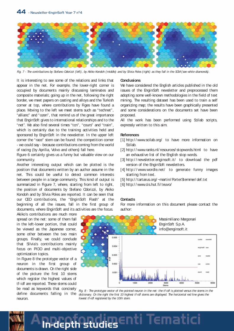
44 - Newsletter EnginSoft Year 7 n°4
It is interesting to see some of the relations and links thatappear in the net. For example, the lower-right corner isoccupied by documents mainly discussing laminates andcomposite materials; going up in the net, following the rightborder, we meet papers on casting and alloys and the Turkishcorner at top, where contributions by Figes have found aplace. Moving to the left we meet stems such as “technet”,“allianc” and “ozen”, that remind us of the great importancethat EnginSoft gives to international relationships and to the“net”. We also find several times “tcn”, “cours” and “train”,which is certainly due to the training activities held andsponsored by EnginSoft in the newsletter. In the upper leftcorner the “race” stem can be found: the competition corner- we could say - because contributions coming from the worldof racing (by Aprilia, Volvo and others) fall here.Figure 6 certainly gives us a funny but valuable view on ourcommunity.Another interesting output which can be plotted is theposition that documents written by an author assume in thenet. This could be useful to detect common interestsbetween people in a large community. This kind of output issummarized in Figure 7, where, starting from left to right,the position of documents by Stefano Odorizzi, by AkikoKondoh and by Silvia Poles are reported. It can be seen thatour CEO contributions, the “EnginSoft Flash” at thebeginning of all the issues, fall in the first group ofdocuments, where EnginSoft and its activities are the focus.Akiko’s contributions are much morespread on the net: some of them fallin the left-lower portion, that couldbe viewed as the Japanese corner,some other between the two maingroups. Finally, we could concludethat Silvia’s contributions mainlyfocus on PIDO and multi-objectiveoptimization topics.In Figure 8 the prototype vector of aneuron in the first group ofdocuments is drawn. On the right sideof the picture the first 10 stemswhich register the highest values oftf-idf are reported. These stems couldbe read as keywords that conciselydefine documents falling in theneuron.
ConclusionsWe have considered the English articles published in the oldissues of the EnginSoft newsletter and preprocessed themadopting some well-known methodologies in the field of textmining. The resulting dataset has been used to train a selforganizing map; the results have been graphically presentedand some considerations on the documents set have beenproposed.All the work has been performed using Scilab scripts,expressly written to this aim.
References[1] http://www.scilab.org/ to have more information on
Scilab.[2] http://www.ranks.nl/resources/stopwords.html to have
an exhaustive list of the English stop words.[3] http://newsletter.enginsoft.it/ to download the pdf
version of the EnginSoft newsletters.[4] http://www.wordle.net/ to generate funny images
starting from text.[5] http://tartarus.org/~martin/PorterStemmer/def.txt[6] http://www.cis.hut.fi/teuvo/
ContactsFor more information on this document please contact theauthor:
Massimiliano MargonariEnginSoft [email protected]
Fig. 7 - The contributions by Stefano Odorizzi (left), by Akiko Kondoh (middle) and by Silvia Poles (right) as they fall in the SOM (see white diamonds).
Fig. 8 - The prototype vector of the pointed neuron in the net: the tf-idf is plotted versus the stems in thedictionary. On the right the first 10 highest tf-idf stems are displayed. The horizontal red line gives thelowest tf-idf registered by the 10th stem.

Newsletter EnginSoft Year 7 n°4 - 45
La deformazione plastica dei metalli ed in particolare lostampaggio a caldo dell’ottone è un processo largamentediffuso che ha sostituito, laddove possibile, i classici pro-cessi di fonderia. Il costo elevato di produzione dei partico-lari in ottone viene sensibilmente abbattuto dall’estrema la-vorabilità e dall’elevato valore di recupero degli sfridi gene-rati in fase di fabbricazione, rendendo quindi economica-mente vantaggioso questo tipo di processo. Volendone ana-lizzare in dettaglio le specificità, il processo parte da barreestruse cilindriche, che vengono tagliate, scaldate alla tem-peratura opportuna (sopra i 700°C), quindi formate il piùdelle volte in un’unica operazione. La tipologia di particola-ri prodotti è estremamente varia, ma la maggior parte ri-guarda la raccorderia per impianti idraulici, dove è possibi-le ottenere il pezzo già con i fori interni, limitando al mini-mo le successive fasi di foratura e lavorazione meccanica.Per far questo si sfrutta l’estrema duttilità del materiale, masi sono anche perfezionate delle macchine con cinematichecomplesse, a forare su cuscino, dove le spine entrano quan-do lo stampo superiore scende sull’inferiore, quest’ultimocontrastato da un cuscino idraulico; oppure configurazioni“a campana”, con due semistampi e spesso dei punzoni chescendono contro una spina principale. La forma sempre piùcomplessa dei particolari da produrre ha portato ad una evo-luzione continua delle presse di stampaggio tradizionali,con carrelli inclinabili dall’utente, ma anche allo sviluppo dinuove macchine con cinematica a ginocchiera o “link-drive”e di recente lo sviluppo di macchine per le quali la cinema-tica dei punzoni è guidata da sistemi idraulici o elettrici, ingrado di muovere i punzoni secondo tempi e velocità sceltedall’utente. Parimenti si è osservato di recente uno svilup-po di nuove leghe di ottone a basso tenore di piombo, ele-mento utile per la rottura del truciolo, ma nocivo a contat-to con l’acqua potabile. Dal punto di vista industriale,l’Italia vede una notevole concentrazione di trasformatori diottone, concentrati nelle provincie di Brescia e di Novara,legati per lo più al mondo della rubinetteria.
Quando Enginsoft si è trovata, ormai più di 10 anni fa, aconfrontarsi con questo particolare processo industriale, cisi è subito accorti della complessità del tema da affrontare.Forge, il software prodotto da Transvalor e specifico per ladeformazione dei materiali metallici, è sembrato lo strumen-to ideale, con la possibilità di implementare tutte le pecu-liarità di questo processo. Ad una prima caratterizzazione inlaboratorio delle leghe di ottone più utilizzate, sono segui-te le prime simulazioni, che hanno dato subito buoni risul-tati, ma che hanno evidenziato il punto critico di questo
processo: il materiale ottone, per la sua duttilità, è solitocreare una notevole quantità di ripieghe, sia in fase di usci-ta in bava, ma anche durante il riempimento delle impron-te. Seguire questo comportamento si è rivelato subito esse-re molto complesso dal punto di vista numerico, dovendo lamodellazione del pezzo tener conto delle zone dove due opiù lembi di materiale tendevano a riunirsi, per effetto delflusso del materiale. Il produttore del software, stimolatodalle esperienze che Enginsoft ha fatto con alcuni impor-tanti gruppi trasformatori di ottone in Italia, ha miglioratoprogressivamente il software, introducendo recentementedelle nuove funzioni di contatto e nuovi traccianti, in gra-do di evidenziare le ripieghe e seguirne l’evoluzione duran-te il processo di stampaggio. Questo sviluppo ha portatoand un significativo vantaggio anche in termini di riduzio-ne di oltre il 30% dei tempi di calcolo. Un altro aspetto spe-cifico di questo processo produttivo riguarda la necessità diconsiderare una lubrificazione differenziata di parti dei pun-zoni o degli stampi e la considerazione di eventuali proble-mi di intrappolamento di gas/lubrificanti. In riferimento alprimo punto, il modello è stato migliorato e consente dispecificare zone a lubrificazione differenziata, mentre perl’intrappolamento di gas/lubrificanti, il modello di calcolotiene conto di questo effetto, evidenziando difetti di riem-pimento legati all’aumento di pressione in aree isolate, ol-tre a consentire di specificare delle tirate d’aria e valutarnel’effetto sulla forma finale. Dal punto di vista del migliora-mento delle cinematiche, sono stati via via perfezionati imodelli di processo per lo stampaggio a forare ed introdot-te nuove cinematiche richieste dagli utilizzatori. Per quan-to riguarda lo stampaggio a forare, il modello attuale repli-ca perfettamente tutti i movimenti della macchina: adesempio se c’è troppo materiale, lo stampo inferiore si muo-ve contro il cuscino prima del contatto con lo stampo infe-riore, quindi i punzoni entrano anticipati rispetto al movi-mento voluto, ma è possibile anche vedere l’apertura dellostampo a pacchetto chiuso, per effetto della spinta internalegata all’entrata dei punzoni. Sono stati implementati car-relli inclinati, il cui movimento è legabile anch’esso alla di-scesa dello stampo inferiore contro il cuscino. Recenti svi-luppi hanno riguardato l’implementazione di presse a ginoc-chiera o di tipo “link-drive”, per le quali la cinematica con-sente una fase di chiusura più graduale, unitamente ad unafase di apertura più rapida. La flessibilità nella definizionedelle leggi di movimento dei punzoni ha consentito di simu-lare senza problemi le nuove macchine ad azionamentoidraulico o elettrico, per l’ottenimento di pezzi senza bava(flash-less). La possibilità di concatenare più movimenti
Simulare con Forge lo stampaggio diottone ed alluminio
STA
MP
AG
GIO
OT
TO
NE
E A
LLU
MIN
IO

46 - Newsletter EnginSoft Year 7 n°4
consente di seguire le varie azioni di chiusura dei punzonie delle matrici in una pressa “a campana”. Per particolari dimaggiori dimensioni, si passa al modello della pressa a bi-lancere/vite, grazie al quale è possibile valutare se la mac-china è in grado di completare la corsa o se esaurisce l’ener-gia disponibile prima di completare il pezzo. Lo sviluppo del software è continuo: ad esempio si sta lavo-rando per aggiungere dei risultati in grado di descrivere conmaggior dettaglio il flusso di materiale attorno ai punzonirispetto allo stampo in movimento contro il cuscino, visua-lizzare meglio le azioni di flessione dei punzoni per effettodel materiale, valutare gli effetti di risucchio del materialenella fase di apertura degli stampi. Sempre più numerosi so-no inoltre gli esempi di utilizzo della funzione di ottimizza-zione automatica contenuta nel programma, ad esempio permodificare la posizione della barra sullo stampo e per ridur-re al minimo il materiale utilizzato, garantendo comunque ilcompleto riempimento e l’assenza di ripieghe sul pezzo.
Da qualche tempo molte aziende che stampano ottone han-no iniziato a dedicarsi anche all’alluminio, per applicazioniprincipalmente nel campo automotive. In questo specificoambito l’esperienza di Transvalor con numerosi stampatoridi alluminio ha garantito fin da subito di poter utilizzare ilsoftware anche in questo ambito, consentendo ai molti uti-lizzatori italiani di poter valutare “in virtuale” le differenzetra un processo a loro ben noto, avendo loro sempre stam-pato ottone, ed un processo non noto, lo stampaggio di al-luminio. Per quanto riguarda le specifiche del processo, nor-malmente vengono utilizzate presse a bilancere/vite, benimplementate nel programma, lo scorrimento del materialealluminio è molto differente e ben riprodotto, grazie allaprecisa caratterizzazione del materiale, e il range delle tem-perature di trasformazione risulta essere più delicato cheper l’ottone.
Volendo cercare una sintesi, si può dire che Forge è unostrumento molto accurato, in particolare nello specifico am-bito dello stampaggio dei metalli non ferrosi. È in grado diconsentire una valutazione a priori molto precisa della fat-tibilità di un particolare con il proprio processo e di inter-venire in virtuale sugli stampi per migliorare la qualità delpezzo. Lo stampo frutto del lavoro di simulazione può esse-re lavorato e mandato in produzione, limitando al minimo leoperazioni di campionatura in linea.Riportiamo di seguito alcuni esempi di utilizzo del program-ma ed i pareri di alcuni utilizzatori italiani.
Caratteristiche comuni a tutte le modalità di stam-paggio:• Importazione da CAD delle geometrie degli
stampi/punzoni/spine in formato .stl e .step;• Definizione del materiale da database, sono
presenti le leghe non ferrose più utilizzate (Cu,ottone, Al, …), sono in fase di caratterizzazio-ne le leghe recentemente messe in commercio(ad esempio “ecobrass”, “Munz”, …);
• Ampia flessibilità nella definizione delle cinematichetramite modelli predefiniti di “pressa” ed opzioni speci-fiche;
• Per la pressa meccanica sono presenti modelli per lapressa biella-manovella, pressa a ginocchiera, pressalink-drive, cinematiche utente (fig. 1);
• Possibilità di specificare attriti differenziati legati aduna superficie degli stampi con differente finitura super-
ficiale e/o lubrificazione indirizzata solo in alcune zone,come ad esempio la testa di un punzone (fig. 2);
• Possibilità di calcolare l’intrappolamento di gas/lubrifi-cante ed i relativi effetti sul completamento del pezzo,valutando l’effetto degli scarichi (venting);
• Possibilità di simulare l’operazione di tranciatura dellebave.
PeculiaritàIl software è in grado di simulare i processi principali distampaggio a caldo di leghe non ferrose:• Stampaggio a bilancere/pressa a vite (fig. 3): pressa “ad
energia” da database, specificata l’energia disponibile
biella-manovella ginocchiera link-drive
Fig. 3 – stampaggio al bilancere: configurazione reale ed esempi di particolari simulati
Fig. 1 – modelli di presse meccaniche presenti nel programma
Fig. 2 - lubrificazione differenziata sulla testa del punzone

STA
MP
AG
GIO
OT
TO
NE
E A
LLU
MIN
IO
Newsletter EnginSoft Year 7 n°4 - 47
ed il numero di colpi il software permette di valutare lequote di chiusura degli stampi;
• Stampaggio “a forare” su cuscino (fig. 4): pressa mecca-nica da database che guida lo stampo superiore, stampoinferiore su cuscino del quale si specifica la resistenza,spine che si muovono in funzione del movimento delcuscino. Forge consente di valutare l’apertura deglistampi legata all’eccessiva pressione esercitata dalmateriale nella fase di entrata delle spine. Tra le opzio-ni sviluppate “ad-hoc” vi sono la possibilità di utilizza-
re carrelli inclinati (fig. 5), diintrodurre nello stampo degliinserti (fig.6), la funzione di“gas trapping” per valutare l’ef-fetto dell’intrappolamento digas/lubrificanti;
• Stampaggio “in campana” (fig.7): grazie alla funzione di conca-tenamento di più analisi, è pos-sibile valutare tutte le azioni dichiusura degli stampi, quindi dientrata delle spine ed infine didiscesa contro il punzone princi-pale;
• Stampaggio “in campana” –chiusura punzone sup., chiusuramatrici, discesa contro punzoneinf.;
• Stampaggio con nuove pressecon punzoni ad azionamento
idraulico/elettrico (fig. 8): la flessibilità di impostazio-ne della cinematica consente di specificare, per ognistampo/punzone, tempi di entrata e leggi di moto diffe-renti, con l’ottenimento di pezzi “flash-less”.
Esempio di risultati ottenibiliFlusso di materialeForge è in grado di simulare correttamente il flusso di ma-teriale nello stampo per effetto della chiusura delle matricie per effetto dell’entrata dei punzoni. Una modifica delle
Fig. 7 – stampaggio in campana: chiusura punzone superiore, chiusura matrici e discesa contro ilpunzone inferiore.
Fig. 8 – stampaggio “flash-less”: vista dei contatti e curvedi movimento dei punzoni.
Fig. 4 – stampaggio a forare su cuscino: configurazionereale
Fig. 5 – stampaggio a forare con spina incli-nata
Fig. 6 – stampaggio a forare con inserto e graficoforze sui punzoni
Fig. 9 – Corpo pompa – confronto tra sequenza interrotta e simulazione e versione ottimizzata.

PARTICOLARI IN OTTONEDi seguito una serie di esempi reali di particolari in ottone, dove la simulazione ha aiutato i progettisti a migliorare la qua-lità del proprio processo produttivo.
Corpo collettore tre vie (fig. 10): la simulazione mostra con l’analisi dei contatti (in blu i contatti con lo stampo, in ros-so le mancanze) che il materiale ha modo di allargarsi verso i raccordi laterali, dando origine ad un risucchio nella parte in-terna dei punzoni principali. Il pezzo reale mostra lo stesso tipo di difetto.
Corpo ad incasso (fig. 11): nell’ipotesi originale di stampaggio si riscontra una ripiega profonda in corrispondenza degli attac-chi laterali esagonali. Sono state studiate diverse ipotesi di stampaggio, che hanno portato ad una eliminazione del difetto.
Corpo valvola (fig. 12): nelle campionature si riscontrano delle ripieghe sul lato delle spinette. La simulazione mostra co-me si forma il difetto e suggerisce degli accorgimenti per eliminare il problema.
Piletta stampata al bilancere (fig. 13): la simulazione evidenzia tutti i difetti riscontrati nella realtà: delle ripieghe sul-la parte esterna (con il risultato “folds”), dovute alla giunzione di flussi, delle ripieghe sulla parete estrusa legate alla chiu-sura di materiale sul profilo ed un risucchio sul lato opposto legato all’estrusione di materiale.
Raccordo a 3 vie con spina inclinata (fig. 14): la configurazione, inizialmente non presente in Forge, è stata implemen-tata sfruttando la flessibilità del codice a trattare cinematiche non-standard. La simulazione ha mostrato come si muove ilmateriale e le mancanze, che a finecorsa si completano dando luogo alle ripieghe presenti nel pezzo reale. Una modificanella posizione della barra di partenza, verificata con la simulazione, ha risolto il problema.
48 - Newsletter EnginSoft Year 7 n°4
Fig. 10 - Corpo collettore tre vie - risucchi su entrata spine.
Fig. 11 - Corpo incasso - configurazione originale con ripiega e configurazione ottimizzata senza ripiega.
Fig. 12 - Corpo valvola con ripieghe lato spinette – vista globale e vista del difetto.
Fig. 13 - Piletta su bilancere – ripieghe esterne, ripieghe su parte estrusa, risucchio su parte piana opposta.
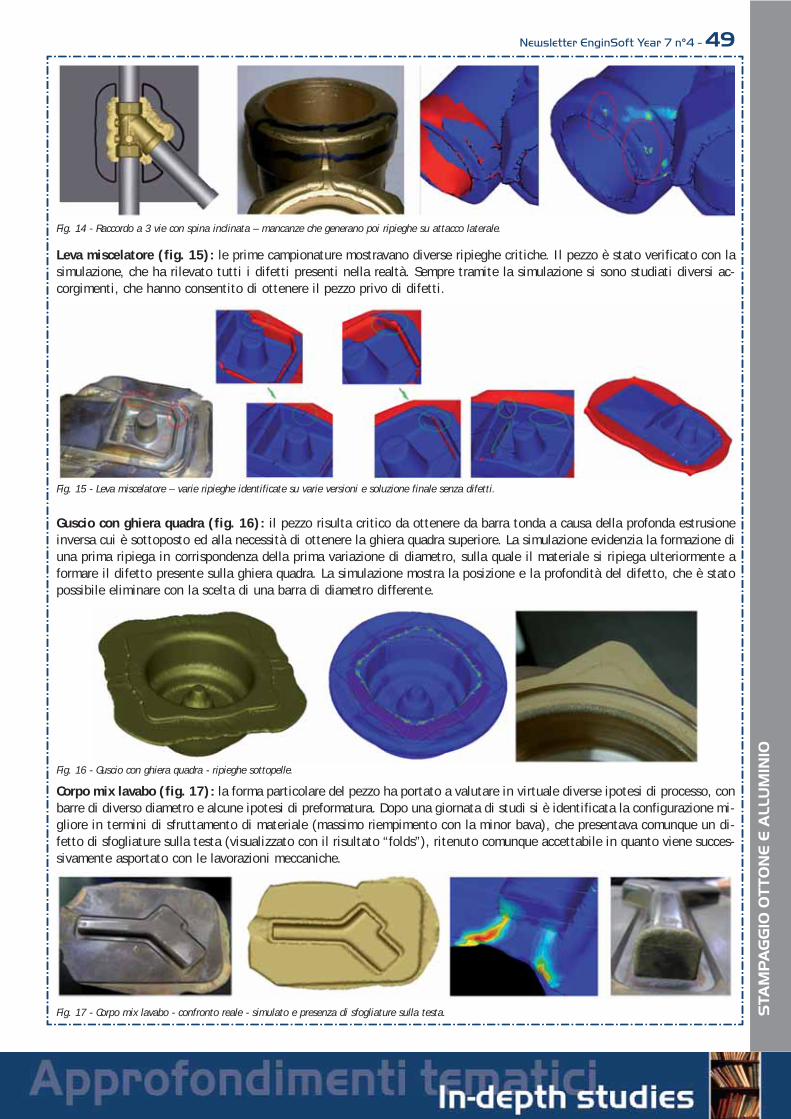
Leva miscelatore (fig. 15): le prime campionature mostravano diverse ripieghe critiche. Il pezzo è stato verificato con lasimulazione, che ha rilevato tutti i difetti presenti nella realtà. Sempre tramite la simulazione si sono studiati diversi ac-corgimenti, che hanno consentito di ottenere il pezzo privo di difetti.
Guscio con ghiera quadra (fig. 16): il pezzo risulta critico da ottenere da barra tonda a causa della profonda estrusioneinversa cui è sottoposto ed alla necessità di ottenere la ghiera quadra superiore. La simulazione evidenzia la formazione diuna prima ripiega in corrispondenza della prima variazione di diametro, sulla quale il materiale si ripiega ulteriormente aformare il difetto presente sulla ghiera quadra. La simulazione mostra la posizione e la profondità del difetto, che è statopossibile eliminare con la scelta di una barra di diametro differente.
Corpo mix lavabo (fig. 17): la forma particolare del pezzo ha portato a valutare in virtuale diverse ipotesi di processo, conbarre di diverso diametro e alcune ipotesi di preformatura. Dopo una giornata di studi si è identificata la configurazione mi-gliore in termini di sfruttamento di materiale (massimo riempimento con la minor bava), che presentava comunque un di-fetto di sfogliature sulla testa (visualizzato con il risultato “folds”), ritenuto comunque accettabile in quanto viene succes-sivamente asportato con le lavorazioni meccaniche.
STA
MP
AG
GIO
OT
TO
NE
E A
LLU
MIN
IO
Newsletter EnginSoft Year 7 n°4 - 49
Fig. 14 - Raccordo a 3 vie con spina inclinata – mancanze che generano poi ripieghe su attacco laterale.
Fig. 15 - Leva miscelatore – varie ripieghe identificate su varie versioni e soluzione finale senza difetti.
Fig. 16 - Guscio con ghiera quadra - ripieghe sottopelle.
Fig. 17 - Corpo mix lavabo - confronto reale - simulato e presenza di sfogliature sulla testa.

50 - Newsletter EnginSoft Year 7 n°4
PARTICOLARI IN ALLUMINIODi seguito sono mostrati una serie di esempi nei quali la simulazione ha aiutato i tecnici a comprendere le motivazioni deidifetti riscontrati nei pezzi, indicando la strada per risolverli.
Braccetto sospensione (fig. 18): particolare di forma molto complessa, dove lo studio ha consentito di minimizzare le ba-ve e di identificare il difetto di riempimento riscontrato nella realtà. Una minima aggiunta di materiale ha consentito di ot-tenere il pezzo privo di difetti.
Tappo per automotive (fig. 19): la particolare forma interna dava luogo ad una ripiega, in una zona critica per la chiusu-ra del tappo, difetto identificato dalla simulazione. Sono stati valutati in virtuale diversi accorgimenti, che hanno consen-tito di eliminare completamente il difetto.
Testa di sterzo motociclistica (fig. 20): lo stampaggio di questo particolare risulta critica per la formazione di ripeghenella zone del profilo intermedio superiore. Lo studio dei flussi effettuato con la simulazione ha spiegato le cause di que-sto difetto: una giunzione di flussi nel caso di risalita non equilibrata di materiale. Si è valutata quindi una modifica nel-lo stampo inferiore, che ha orientato meglio il materiale verso il profilo, ha eliminato il difetto ed ha consentito anche unrisparmio di materiale, scaricando una zone che poi viene lavorata alla macchina utensile.
Perno (fig. 21): l’errata scelta della barra può portare ad un flusso non corretto di materiale verso la zona esterna e quin-di al riempimento per ritorno e ripiega in prossimità delle razze. La simulazione ha aiutato a comprendere come si chiudeil materiale su se stesso e quindi a testare varie geometrie di barra, fino a trovare quella che garantisce la miglior qualitàdel pezzo.
Fig. 18 - Braccetto - Riduzione delle bave e mancanza di riempimento di un dettaglio.
Fig. 19 - Tappo - Giunto nella zona inferiore del rilievo e versione senza difetto.
Fig. 20 - Testa di sterzo motociclistica - Giunti legati alla chiusura dei flussi.
Fig. 21 - Perno - il materiale si allarga verso l’esterno, chiudendosi quindi su se stesso e formando le ripieghe sulle razze.

Newsletter EnginSoft Year 7 n°4 - 51Raccordo (fig. 22): il pezzo, molto massivo, ad una prima analisi non mostrava dei difetti significativi di riempimento. Ilcliente ha però evidenziato la presenza di bolle in corrispondenza della linea di trancia delle bave, difetti considerati criti-ci per la qualità del pezzo. La simulazione ha mostrato un aumento importante di temperatura nella zone di uscita del ma-teriale in bava, ad un livello sufficiente per innescare le bolle nel materiale. Tramite la simulazione si sono testate diverseipotesi di temperature iniziali di barra, identificando il compromesso migliore per garantire un flusso corretto di materiale,una sollecitazione non eccessiva della pressa e temperature sulle chiusure non eccessive, ottenendo quindi il particolare conla qualità richiesta.
Fig. 22 - Raccordo - bolle su linea di bava legate a T troppo elevata e pezzo finale privo di difetti.
BRAWO BRASSWORKING – Cividate Camuno (BS)Ogni nuovo pezzo passa prima dalla simulazione pereliminare mancanze e ripieghe. Dove è possibile, testiamonoi e poi proponiamo ai nostri clienti modifiche chemigliorano la producibilità e spesso anche la funzionalità diquello che siamo chiamati a produrre. Fondamentale èl’interfaccia costante con Enginsoft, che ci supportanell’implementazione di nuove configurazioni e ci fa crescerenella coscienza dell’analisi dei risultati, ma anche ilconfronto con Transvalor, che ci segue nell’implementazionedi funzioni sempre più complesse, ma che rendono lasimulazione sempre più vicina alla realtà.
ZUCCHETTI MARIO – Antegnate (BG)La simulazione della deformazione della billetta tra glistampi rappresenta un valido aiuto per l’ottimizzazione delprocesso di stampaggio a caldo. L’analisi dei risultati dellasimulazione consente di valutare i problemi sul pezzo e suglistampi, di testare versioni modificate e deliberare stampi esequenza di produzione dopo aver individuato la soluzioneottimale. In questo modo si riducono al minimo i tempi dimessa a punto “trial and error” arrivando alla soluzioneottimale senza impegnare fisicamente le presse e la materiaprima. Forge è stato essenziale anche per far crescererapidamente delle nuove figure tecniche, che hanno potutostampare “in virtuale” un numero rilevante di particolari(nell’ordine di 60 pezzi nei primi 3 mesi), risolvendo, conl’aiuto degli esperti di stampaggio presenti da anni inazienda, sia problemi “storici” di stampaggio, che via viasupportando le scelte per nuovi particolari.
METALPRINT – Ponte S. Marco – Calcinato (BS)Abbiamo scelto Forge come uno strumento utile a farcicrescere nello specifico dello stampaggio di alluminio, uncampo a noi poco noto. Usando lo strumento abbiamo messoa punto il nostro processo e siamo stati in grado di proporciai nostri clienti come realtà in grado di supportarli nelpercorso di analisi di fattibilità di un pezzo. In diverseoccasioni, il software è stato elemento determinante perprendere una commessa, garantendo a-priori il risultatofinale, prima promesso solo sulla carta.
FONDERIA F.LLI MASPERO – Monza (MI) La nostra produzione è caratterizzata da particolari spessomolto complessi, in leghe non ferrose spesso non comuni(bronzo-alluminio, cupro-nickel, …), che abbiamo trovatogià disponibili nel database dei materiali di Forge. Leesperienze iniziali con il programma ci hanno spinto ameglio approfondire i dati di processo per inserirli nellasimulazione, attraverso un monitoraggio delle nostremacchine. Questo ci ha portato ad un maggiore controllo deiparametri fondamentali dello stampaggio, con unmiglioramento complessivo della qualità dei pezzi prodottied una migliore ripetibilità delle operazioni. Si è ottenutauna reale ottimizzazione del nostro processo, con ricadutesensibili sul conto economico. L’evoluzione del mercato ciporterà ad affrontare prodotti sempre più difficili e dinicchia, per i quali avere questo strumento ci garantiscesicurezza nell’affrontare i progetti più impegnativi edinnovativi, dando un notevole impulso alla nostracompetitività.
STA
MP
AG
GIO
OT
TO
NE
E A
LLU
MIN
IO

52 - Newsletter EnginSoft Year 7 n°4
condizioni di processo, quali ad esempio il cambio della bar-ra (dimensioni e posizione) o modifiche apportate alla geo-metria delle matrici, portano a dirette conseguenze sul ri-sultato finale, indicando la via per procedere verso il miglio-ramento del pezzo. Un primo caso mostra la sequenza diriempimento di un corpo pompa in ottone (fig. 9): la simu-lazione ricalca in modo fedele quanto accade nella realtà,che è possibile comprendere solo effettuando delle sequen-ze interrotte.
Procedere con la simulazione del processo di stampaggio,valutando a priori i problemi, consente di testare diverseconfigurazioni e scegliere la migliore, riducendo al minimo itempi ed i costi di campionatura in stampaggio.
Mancanze e ripiegheI risultati che normalmente si utilizzano per capire il flussodi materiale sono i contatti e le ripieghe. Per i primi, in blusono riportate le aree di contatto con stampi/punzoni, inrosso le mancanze. Per le ripieghe, il software evidenzia conil colore rosso le zone dove il materiale ripiega su se stes-so. Appositi sensori consentono di valutare anche come simuove la ripiega durante la stampata e quindi aiutano a ca-pire se rimane interna o esce sulle bave.
OTTIMIZZAZIONE AUTOMATICAForge è l’unico software di simulazione di stampaggio ad in-cludere una funzione per l’ottimizzazione automatica.Partendo da un progetto di riferimento, è possibile specifi-care il range di variabilità di alcuni parametri (ad es. dimen-sione della barra, sua posizione sullo stampo, …) e chiede-re al software di trovare i migliori valori per soddisfare gliobiettivi (ad es. riempimento dello stampo, assenza di ri-pieghe, …).
Nell’esempio seguente, è stato ottimizzato uno stampo perla produzione di un raccordo a T in ottone. I parametri im-postati sono un diametro barra tra 36,8mm e 55,2mm, una
lunghezza barra tra 48mm e 72mm ed una possi-bile variazione rispetto alla posizione iniziale di-5mm lungo Y. Si chiede all’ottimizzatore di tro-vare i migliori valori per minimizzare il materialeimpiegato.
Primo risultato ottenuto: con una barrad=38,13mm, L=49,2mm e dY=-3,7, si ottiene ilriempimento del pezzo con il minimo materialepossibile, ma si riscontrano delle ripieghe.
Richiedendo come vincolo anche l’assenza di ri-pieghe, il software individua un’altra configura-zione, che necessita di molto più materiale.Partendo infine da barra coricata, si ottiene lamigliore soluzione, con riempimento completosenza ripieghe e con un significativo risparmio dimateriale (-15% rispetto all’ipotesi iniziale)
L’ottimizzatore valuta diverse generazioni di indi-vidui, selezionando via via i migliori per conver-gere alla combinazione di valori e parametri checonsentano di ottenere i migliori obiettivi (com-pleto riempimento dell’impronta, nel rispetto deivincoli imposti (assenza di ripieghe).
Per maggiori informazioni:Marcello Gabrielli - [email protected]

Newsletter EnginSoft Year 7 n°4 - 53
It is now well known that 3D CFD simulations can give detailedinformation about fluid and flow properties in complex 3Ddomains and that, on the other hand, 1D CFD simulations cangive important information at system levels, i.e. about theperformances of an entire system of internal flows. Thedrawbacks of the two simulation methods are that the formerrequires high computational costs while the latter cannotcapture complex local 3D features of the flow. Therefore, the twosimulations methods are to be seen as complementary, indeed acoupling of the two methods can use the strongest points of thetwo methods while minimizing the drawbacks. In particular,with a multi-scale modelling approach (achieved by coupling 1Dand 3D codes) it is possible to simulate large and complexdomains by modelling the complex parts with a 3D approach andthe rest of the system with a 1D approach. This methodology canprovide detailed information only where needed while providingsystem level information in the rest of the domain; thisminimizes the computational costs. Moreover, the multi-scaleapproach avoids the need of imposing approximated boundaryconditions to the 3D simulation which would badly affect thereliability of the simulation itself.EnginSoft has a long and important experience both in 1D and3D simulation modelling (with ANYS Fluent, ANSYS CFX andFlowmaster) and is active in multi-scale simulations. There aredifferent methodology for coupling 1D and 3D codes. Thecoupling methodologies can be divided in manual or automaticdepending on the method of data transfer between the twocodes, or in one-way or two-way depending whether bothsystems mutually influence each other or not. Manual one-waycoupling between 1D and 3D CFD codes is a standard practice inEnginSoft. Usually the complex components in the systems (suchas valves, orifices, heat exchangers, vessels) are modelled in 3Dwith ANSYS CFX or ANSYS Fluent. The characterization of thesecomponents allows the definition of an equivalent 1Dcomponent used inside the 1D model of Flowmaster. Using thissimple approach all the detailed information gained with the 3Dsimulations are embedded and used inside the 1D system model.EnginSoft is also actively investigating automatic one-way and
two-way coupling methodologies between Flowmaster andANSYS Fluent and ANSYS CFX.The coupling possibility is not limited to CFD field but canextend to multi-physics. An example of multi-physics one-waycoupling is the simulation of vibrations in piping systems (e.g.compressed gas systems, blow-down systems); this simulation isperformed by modelling the pressure wave propagation insidethe piping system with Flowmaster and passing the forcesexerted by the internal flow to ANSYS for a mechanical analysis.EnginSoft has performed several vibration analyses for differentcustomer using this one-way multi-physics approach with asemi-automatic procedure. Another example of multi-physicstwo-way coupling is the simulation of thermal deformation ofsolid structures and the fluid flow though them. In this caseboth systems influence each other so that the coupling needs tobe two-way and automatic. EnginSoft has developed a fully-automatic interface between Flowmaster and a thermo-mechanical code for such a simulation. Finally, in this frameworkit is worth mentioning that Flowmaster can be directly coupledwith mode-FRONTIER allowing multi-objective optimizations.EnginSoft is active in this field with different optimizationprojects involving 1D CFD and Flowmaster.
Vincent Soumoy of EURO/CFD and David Kelsall of FlowmasterLtd, both members of the NAFEMS CFD Working Group, providean overview of the recent NAFEMS UK seminar on coupling 1Dand 3D.The benefits of coupling 1D and 3D CFD codes have long sincebeen recognised. Automotive and aerospace companies haveused 1D codes to gain a better understanding of systemperformance (such as fuels systems), whilst 3D codes are usedto analyse detailed behaviour within and around keycomponents. With that in mind, the NAFEMS CFD Working Grouprecently arranged a seminar at the Heritage Motor Centre inGaydon to understand the benefits of such links and assess thecurrent state of the art. Approximately 40 interested partiesfrom across the NAFEMS membership attended to hear a numberof interesting and thought-provoking presentations from variousspeakers.Darren Morrison started the technical presentations by sharingan interesting view on the subject from the perspective of alarge aerospace company (AIRBUS). Validation is seen as
Coupling 1D and 3D CFDThe Challenges and Rewards of Co-Simulation
"This article originally appeared inthe October 2010 edition ofBenchmark and has been reprintedwith permission from NAFEMS"
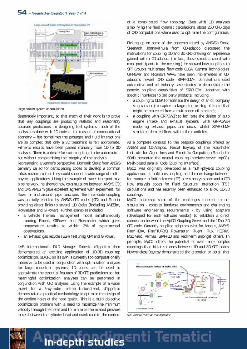
54 - Newsletter EnginSoft Year 7 n°4
desperately important, so that much of their work is to provethat any couplings are producing realistic and reasonablyaccurate predictions. In designing fuel systems, much of theanalysis is done with 1D codes – for reasons of computationaleconomy – but sometimes the passages and fluid interactionsare so complex that only a 3D treatment is felt appropriate.Hitherto results have been passed manually from 1D to 3Danalyses. There is a desire for such couplings to be automatic –but without compromising the integrity of the analysis.Representing a vendor’s perspective, Domonik Sholz from ANSYSGermany called for participating codes to develop a commoninfrastructure so that they could support a wide range of multi-physics applications. Using the example of tracer transport in apipe network, he showed how co-simulation between ANSYS CFXand LMS AMESim gave excellent agreement with experiment, forflows in- and around- pipe junctions. The inter-code couplingwas partially enabled by ANSYS CFD codes (CFX and Fluent)providing direct links to several 1D Codes (including AMESim,Flowmaster and GTPower). Further examples included: • a vehicle thermal management model simultaneously
running Fluent, GTPower and Flowmaster which givestemperature results to within 2% of experimentalobservations;
• an exhaust gas recycle (EGR) featuring CFX and GTPower.
LMS International’s R&D Manager Roberto d’Ippolito thendemonstrated an exciting application of 1D-3D coupling:optimization. 3D CFD on its own is currently too computationallyintensive to be used in conjunction with optimization analysesfor large industrial systems. 1D codes can be used toapproximate the essential features of 3D CFD predictions so thatmeaningful optimization analyses can be performed inconjunction with CFD analyses. Using the example of a waterjacket for a 5-cylinder in-line turbo-diesel, d’Ippolitodemonstrated a practical methodology to optimise the design ofthe cooling holes of the head gasket. This is a multi objectiveoptimization problem with a need to maximize the minimumvelocity through the holes and to minimize the related pressurelosses between the cylinder head and crank-case in the context
of a complicated flow topology. Even with 1D analysessimplifying the fluid dynamic calculations, about 250 CPU-daysof CFD computations where used to optimise the configuration.
Picking up on some of the concepts raised by ANSYS’s Sholz,Sreenadh Jonnavithula from CD-adapco discussed themotivations for coupling 1D and 3D CFD drawing on experiencegained within CD-adapco. (In fact, these struck a chord withmost participants in the meeting.) He showed how couplings toSPT Group’s multiphase flow code OLGA, Gamma Technologies’GT-Power and Ricardo’s WAVE have been implemented in CD-adapco’s newest CFD code, STAR-CCM+. Jonnavithula usedautomotive and oil industry case studies to demonstrate thegeneric coupling capabilities of STAR-CCM+ together withspecific interfaces to 3rd party products, including:• a coupling to OLGA to facilitate the design of an oil company
slug-catcher (to capture a large plug or slug of liquid thatmight be projected from a multiphase oil pipeline);
• a coupling with GT-POWER to facilitate the design of autoengine intake and exhaust systems, with GT-POWERmodelling exhaust pipes and ducts, whilst STAR-CCM+simulated detailed flows within the manifolds.
As a complete contrast to the bespoke couplings offered byANSYS and CD-Adapco, Pascal Bayrasy of the FraunhoferInstitute for Algorithms and Scientific Computing (FraunhoferSCAI) presented the neutral coupling interface server, MpCCI(Mesh-based parallel Code Coupling Interface). MpCCI was originally developed as a multi-physics couplingapplication. It facilitates coupling and data exchange between,for example, a finite element (FE) stress analysis code and a CFDflow analysis codes for Fluid Structure Interaction (FSI)calculations and has recently been enhanced to allow 1D-3Dcouplings. MpCCI addressed some of the challenges inherent in co-simulation - complex hardware environments and challengingsoftware engineering requirements - by using adapters(developed for each software vendor) to establish a directconnection between the MpCCI Coupling Server and the 1D or 3DCFD code. Currently coupling adaptors exist for Abaqus, ANSYS,Fine/HEXA, Fine/TURBO, Flowmaster, Fluent, Flux, ICEPAK,MSC.Marc, Permas, STAR-CD and RadTherm amongst others. Inprinciple, MpCCI offers the potential of even more complexcouplings than bi-lateral ones between 1D and 3D CFD codes.Nevertheless Bayrasy demonstrated the attention to detail that
Large aircraft system co-simulation
Full vehicle thermal management
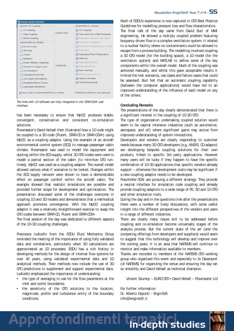
Newsletter EnginSoft Year 7 n°4 - 55
has been necessary to ensure that MpCCI produces stable,convergent, conservative and consistent co-simulationsolutions.Flowmaster’s David Kelsall then illustrated how a 1D code mightbe coupled to a 3D code (Fluent, STAR-CD or STAR-CCM+) usingMpCCI as a coupling adaptor. Using the example of an aircraftenvironmental control system (ECS) to manage passenger cabinclimate, Flowmaster was used to model the equipment andducting within the ECS supply, whilst 3D CFD codes were used tomodel a partial section of the cabin (to minimize CFD run-times). MpCCI was used as a coupling adapter. The overall modelallowed various what-if scenarios to be tested. Changes withinthe ECS supply network were shown to have a demonstrableeffect on passenger comfort within the aircraft cabin. Theexample showed that realistic simulations are possible andprovided further scope for development and optimization. Thepresentation discussed some of the challenges overcome incoupling 1D and 3D models and demonstrates that a methodicalapproach promotes convergence. With the MpCCI couplingadaptor it was a relatively straightforward exercise to swap theCFD codes between STAR-CD, Fluent and STAR-CCM+The final session of the day was dedicated to different aspectsof the 1D-3D coupling challenges.
Francesca Iudicello from the ESDU Fluid Mechanics Groupreminded the meeting of the importance of using fully validateddata and correlations, particularly when 3D calculations areapproximated as 1D processes. ESDU has a rich history indeveloping methods for the design of internal flow systems forover 40 years, using validated experimental data and 1Danalytical methods. Their methods now include the use of 3DCFD predictions to supplement and support experimental data.Iudicello emphasized the importance of understanding:• the type of averaging to use for the flow parameters at the
inlet and outlet boundaries;• the sensitivity of the CFD solutions to the location,
magnitude, profile and turbulence entity of the boundaryconditions.
Much of ESDU’s experience is now captured in CFD Best PracticeGuidelines for modelling pressure loss and flow characteristics.The final talk of the day came from David Burt of MMIengineering. He showed a multiply coupled problem featuringbuoyancy driven flow in a complex ventilation system. It relatedto a nuclear facility where no contaminants could be allowed toescape from a process building. The modelling involved couplinga 3D CFD model (for the building space), a 1D model (for theventilation system) and MATLAB to define some of the keycomponents within the overall model. Much of the coupling wasachieved manually, and whilst this gave acceptable results itlimited the test scenarios, use cases and failure cases that couldbe assessed. Burt felt that an automatic coupling capability(between the computer applications) would have led to animproved understanding of the influence of each model on anyof the others.
Concluding RemarksThe presentations of the day clearly demonstrated that there isa significant interest in the coupling of 1D-3D CFD.The type of organisation undertaking coupled solution wouldseem to be capital intensive industries (such as automotive,aerospace, and oil) where significant gains may accrue fromimproved understanding of system interactions.Developers and vendors are clearly responding to customerneeds because many 3D CFD developers (e,g, ANSYS, CD-adapco)are developing bespoke coupling solutions for their ownproducts, linked to specific 3rd party applications. Howevermany users will be lucky if they happen to have the specificcombination of 1D-3D applications that specific vendors alreadysupport – otherwise the development costs may be significant ifa new coupling adaptor needs to be developed.Fraunhofer-SCAI are pursuing a different strategy. They providea neutral interface for simulation code coupling and alreadyprovide coupling adaptors to a wide range of FE, 3D and 1D CFDand other simulation tools.During the day and in the questions time after the presentationsthere were a number of lively discussions, with some usefulinsight into the different perspectives of the vendors and usersin a range of different industries.There are clearly many issues still to be addressed beforecoupling and co-simulation become universally stages of theanalysis process. But the current state of the art (and thecompeting offerings from developers and suppliers) would seemto suggest that this technology will develop and improve overthe coming years. It is an area that NAFEMS will continue tomonitor and make information available to members.Thanks are recorded to members of the NAFEMS CFD workinggroup who organised this event and especially to Jo Davenport(of NAFEMS) for organizing the venue and ensuring the day ranso smoothly and David Kelsall as technical champion.
Vincent Soumoy – EURO/CFD • David Kelsall – Flowmaster Ltd
For further information:Dr. Alberto Deponti - [email protected]
The links with 1D software are fully integrated in the STAR-CCM+ user interface

56 - Newsletter EnginSoft Year 7 n°4
Epsilon Euskadi, situated in TheBasque Country in Spain, wasfounded in 2003 as a racing teamparticipating with two cars in the“Nissan World Series” and in thisshort time they have become aTechnological Innovation Centreunique in the world.The Master in TechnicalSpecialization within AutomobileRacing, METCA, is the result ofcollaboration between EpsilonEuskadi and the University ofMondragón that, in the six years since starting in 2005, hasbecome an international benchmark. The course providesmore than 1,700 teaching hours over 11 months and thisyear the participation included 32 students from 6 differentcountries.AperioTec (Barcelona, Spain) and modeFRONTIER co-sponsored the course together with other companies and forthe first time was involved in training the students in the useof optimization within the "CAD & Calculation" coursemodule.Here we provide parts of an interview held with Mr. JoanVilladelprat, the President of Epsilon Euskadi, to gain hisimpressions on the progress of Epsilon Euskadi, the METCAprogram and the usefulness of the modeFRONTIER software.
1. What were the main reasons for initiating the METCA?Joan Villadelprat: One of the main reasons that led us to startthe Masters, and Epsilon in general,was to add special emphasis tomotorsport that went beyond mereshow. The main objective is to trainthe next generation of engineerswho wish to develop their career inthe world of high competition andindustrial sectors that require a highdegree of technological expertiseand innovative components. Theambitious and unique combinationof theory and practice that theMETCA degree offers provides aunique opportunity to educate thenext generation of engineerscapable of reaching and meeting thehighest level in motorsport as wellas in other industries in whichtechnology and innovation are thecornerstones.
2. Why it is considered a world pioneering master?JV: It is a pioneering master due to its combined theoreticaland practical orientation. Students not only receivetheoretical knowledge from high level teachers and lecturersbut within the same program they implement this knowledgein the workshops, the wind tunnel, the engineering designdepartment and with the Epsilon teams that participate inthe World Series by Renault championship. Thanks to thisapproach, every day the students are faced with realsituations and problems from which they obtain a uniqueexperience that will enable them, tomorrow, to confidentlyaccept any challenge.
3. Are you aware of any former METCA students currentlyworking on a racing team? If so, in what team and whatfunctions are they carrying out?JV: Year 2010 is the sixth promotion, but of the previous fivepromotions, we are aware of eight alumni who work or haveworked as engineers in Formula 1, in Sauber, Renault, Toyotaand Red Bull. We also know of students who work in othercompetitions such as the GP2 and the Le Mans Series wherethey work as engineers with different responsibilities.
4. Would you highlight any aspects of the new Epsilonfacilities in Vitoria?JV: In January 2010 we moved to the new Innovation Centre,located in the Parque Tecnológico de Álava, Vitoria. Here wehave 17.000 square metres of facilities equipped with thelatest technologies to meet the four basic areas that Epsilonfocuses on: R&D, manufacture, competition and training.
These new facilities enable us to face manymore challenges and to empower morestudents. For METCA we have a classroomfully equipped with the latest software andhardware in addition to using the rest of thefacilities for their practical classes andprojects, the most important of which is theWind Tunnel. This is a unique facility in Spainbased on its features - size, power andmoving floor - making it the most modern inEurope.
5. Can you please tell us about the currentuse of the wind tunnel at the centre?JV: The wind tunnel at the centre is usedboth for our own projects and projects forothers. Our current projects include theprototype development of a Le Mans car inaccordance with current specifications and aprototype Formula 1 car. But we do not only
Interview with Joan Villadelprat,President of EPSILON EUSKADI
Joan Villadelprat, the Presidentof Epsilon Euskadi.

Newsletter EnginSoft Year 7 n°4 - 57test vehicles, we can study any surfaceexposed to air flow to improve itsaerodynamic efficiency. In the tunnel wehave tested the official Nike football forthe Spanish, Italian and English footballleagues and the Bell helmet that cyclistAlberto Contador used for the time trials inthe Tour de France this year. We have alsodone tests on new profiles for wind turbineblades, solar panels and high speed trains.
6. Why did you decide to includemodeFRONTIER in this master?JV: The aim of the master is to provide amulti-disciplinary education to students inorder to broaden their knowledge indisciplines such as aerodynamics, vehicledynamics, powertrain (engine, gearbox andtransmission), calculation and simulation,CAD, programming, track engineering andteam management. modeFRONTIER offers a good tool tocreate very comprehensive process simulations andoptimization calculations managing other software programsso it is necessary that students know and understand thissoftware tool.
7. Logical, but was there were some notable non-technicalaspects?JV: The close relationship we have with AperioTec was amajor reason to opt for this software. The tool itself is notuseful unless there is a leading technology partner guidingand helping users to best use it.
8. Were your expectations met with this new section of thecourse?JV: We have reached the point where we have closed thedevelopment cycle by using automatic optimizationtechniques instead of just using experience and knowledge.It is still early to assess with certainty, but our primaryexpectation has been fulfilled by obtaining optimal solutionsto engineering problems which traditionally would not havebeen possible.
9. Each student must complete a final master project; haveyou any idea of possible projects to be undertaken bystudents using modeFRONTIER?JV: There are six projects that will use modeFRONTIER with atotal of ten students working with this tool. I could mentionone or two, but they are all very interesting, so it is difficultto highlight any in particular.
10. What is the overall impression that the students hadof this new section?JV: Their initial assessment was very positive but they haverequested to have more time with the tool, something whichwe sort of anticipated. Being the first year, we consider thisour first trial, but next year we will surely double number of
classes dedicated to optimization and use withmodeFRONTIER.
11. What might be future opportunities foroptimization using modeFRONTIER in yourprocesses or designs?JV: Applications and areas where we canoptimize the designs are so diverse thatoptimization can be performed in virtually allvehicle areas. The capabilities of this type ofsoftware tool enable us to precisely andconfidently obtain optimal designs.
12. Epsilon provides engineering services forcompanies with high technological value, sowhat are the opportunities to utilize some ofthe modeFRONTIER features?JV: The possibilities are vast. Our companyphilosophy at Epsilon is that we use intellect andthe available tools to provide high added-value
to various industrial sectors. Reaching an optimal solutionensures the success of any project, so that with these tools,we can become even more empowering and reliable.
13. Epsilon, together with other companies, has developeda new electric car concept called "Hiriko, Diving Mobility"that is sure to revolutionize the automotive industry andurban mobility in the future. What has been the role ofEpsilon Euskadi in this project?JV: Our role is to lead the "city car" prototype production ofthe new urban concept vehicle that MIT has developed,contributing our technical knowledge and integrating theexpertise of different automotive industry providers. Thisrequires development and production, via a newdecentralized model, of the first vehicle of its kind in theworld. Without doubt, the research and development ofinnovative products and technologies fits perfectly withinthe Epsilon philosophy, which goes beyond that of thecompetition. It is a challenge that goes beyond meretechnology, also appealing to social responsibility.
14. What results have Epsilon Euskadi achieved in thevarious competitions?
Driver Albert Costa signing autographswith Commercial Director Jordi Caton.

58 - Newsletter EnginSoft Year 7 n°4
JV: Epsilon Euskadi participates withfour cars in the Eurocup Formula Renault2.0 and with two cars in the FormulaRenault 3.5 or World Series. The Renault2.0 would be a natural first step foryoung people moving from karting tocars. Here the cars are simple but
certainly provide a great school. Our four drivers have donevery well and three of the four have been on the podium onoccasion. Substitute drivers were also on the podium andwon some races, which gives an idea of the team'scompetitiveness. The World Series would be the next step andis generally the prelude to Formula 1.
Drivers such as Kubicaand Alguersuari grew upwithin Epsilon, butothers like Vettel,Kovalainen and Alonsohave also driven here. Inthe Renault 3.5 categorywe currently have AlbertCosta who is one of the
most promising young Spanish motorsport drivers and winnerof the Eurocup and WEC (West European Cup) with Epsilon in2009. Despite some physical problems he had this season hehas had an extraordinary first year in the category, withseveral podiums to his credit.
15. And finally, your expectation was to enter F1 in 2010but this did not come about. Is there some expectationthat Epsilon could enter this competition next year?JV: Entering Formula 1 is one of our goals, but not the onlyone. And this license enabled direct entry, but neither will itbe the only one. Epsilon will continue with its industrial andautomotive projects. And among these projects is that ofentering Formula 1 because it is the ultimate expression ofmotor racing and technology, basic principles of ourcompany. While working on a new opportunity, we will alwayscontinue with our educational projects, competition,manufacturing and R&D.
AperioTec and modeFRONTIER in facebook and twitterThe original Spanish version of the ”Interview with JoanVilladelprat, President of Epsilon Euskadi” can be foundin the Aperiotec webpage and was even published on17
thOctober 2010 in the official pages of Epsilon
Euskadi on Facebook and Twitter.
Newsletter EnginSoft Year 7 n°4 - 59
Riganti è una delle realtà più importanti inItalia per quanto riguarda la produzione di par-ticolari in acciaio mediante forgiatura al ma-glio. Nello stabilimento di Solbiate Arno (VA) siproducono fin dal lontano 1891 particolari daun minimo di 5kg ad un massimo di 1500kg in
acciai comuni al carbonio ed inox, ma anche in leghe speciali(Monel, Inconel, Chromium-Duplex, Incoloy, etc.) per ogni set-tore della meccanica: veicoli industriali, impianti petrolchimici,ferrovie, motori marini e industriali, ruote dentate e cambi, ae-ronautica, … L’attività ruota attornoal processo di stampaggio al maglio,con le linee da 10.000 kgm, 16.000kgm, 25.000 kgm, 2 linee da 32.000kgm, 2 linee da 35.000 kgm e l’ulti-ma installata da ben 40.000 kgm,che consentono con diversi colpi diottenere particolari di diametro fino a 1m e forme molto com-plesse, particolari che poi sono trattati termicamente e lavoratial grezzo o al finito. Visitate il sito di Riganti all’indirizzo: www.riganti.com
L’utilizzo di FORGE nella progettazioneRiganti è sempre stata sensibile alle innovazioni tecnologiche ingrado di implementare e ottimizzare la produzione ed il “servi-ce” relativo. Fra le prime ditte ad implementare l’uso del CAD 3D per la pro-gettazione degli stampi è stata anche la prima industria di stam-paggio in Italia, a credere nella simulazione di processo, sce-gliendo sin dal 1999 Transvalor e l’assistenza tecnica e formati-va di EnginSoft. L’uso di magli di medie-grandi dimensioni, è unadelle caratteristiche che distinguono il prodotto Riganti ed ilsoftware Forge è stato personalizzato ed implementato secondole particolari necessità del processo di formatura con magli acontraccolpo e doppio effetto.Il continuo affinamento del programma, ha reso i risultati dellesimulazioni sempre più realistici, rendendo Forge insostituibilesia in fase di valutazione preventiva che nella fase di ottimizza-zione. Possiamo dire che l’esperienza analitico-scientifica conForge, non sostituisce completamente la conoscenza pratica del-l’esperto forgiatore, ma la affianca e la sostiene, dando logica espiegazione ad un patrimonio quasi esoterico, frutto di traman-date conoscenze e di svariati anni di lavoro sul campo, legateperò al singolo individuo e non al know-how aziendale. Se al mo-mento della scelta di Forge, l’obiettivo primario era quello del-
l’eliminazione dei difetti di stampaggio (ripieghe, cricche perelevato scorrimento interno, mancanze), sono subito apparseutili altre caratteristiche legate alla simulazione di processo.L’uso di Forge si è rivelato fondamentale nell’esame di fattibili-tà preventiva dando così modo alla parte commerciale di esplo-rare nuovi mercati e nuove tipologie di prodotto, con la sicurez-za di soddisfare una fornitura, anche al limite delle possibilitàproduttive dei magli a disposizione. Forge si è dimostrato indi-spensabile sia per l’ottimizzazione di commesse ad elevato nu-mero di pezzi, ma ancor di più per lotti di produzione con bas-so numero di particolari di grossa dimensione, per i quali non èfattibile una fase di prototipazione e per i quali un errore pro-gettuale è inaccettabile, per il grosso dispendio economico e peri conseguenti ritardi nella consegna dei pezzi.
Perché EnginSoft e FORGE in RigantiL’uso costante di Forge consente di creare un data base suddivi-so per famiglie di prodotto, a disposizione di quei clienti che siavvicinano per la prima volta alla Riganti ed ai suoi prodotti.L’ottima visualizzazione dei risultati facilita la comprensione an-che a persone meno esperte del settore, diventando un ottimostrumento di comunicazione con il cliente finale, soddisfando leesigenze relative alla previsione dell’andamento fibre e permet-
tendo la tracciabilità del nucleo billetta, consentendo in alcunicasi, a pari qualità, l’uso di acciai da colata continua in sostitu-zione dei più costosi in laminato. Il dott. Marco Riganti ci hadetto: “Ho visitato la Transvalor nel 1999 per rendermi contopersonalmente del livello tecnico di questa azienda e del suosoftware Forge, prima di deciderne l’acquisto. L’impressione dieccellenza che ne ricavai allora si è confermata negli anni e perquesto continuo a sostenere l’importanza di questa scelta per ilprogresso della mia azienda”. “La piena soddisfazione nei risul-tati e nell’affidabilità, hanno reso nel tempo insostituibileForge. Ogni anno siamo impazienti di ricevere la nuova versioneper applicare nel concreto le diverse migliorie sempre presenti(miglioramento dei contatti e tracciatura delle ripieghe, ottimiz-zazione, strumenti per rendere più rapida la soluzione e più pre-cisa l’analisi dei risultati, …). Il continuo lavoro di sviluppo delprogramma, a cura di Transvalor, e l’assistenza continua diEnginSoft nell’implementazione di progetti sempre più comples-si, sono elemento essenziale per utilizzare quotidianamente que-sto strumento e trarne il massimo vantaggio”, dichiarano DarioBressan, responsabile dell’Ufficio Tecnico e Franco Cermisoni,l’utilizzatore del programma.
RIGANTI SpAAcciaio stampato al maglio dal 1891
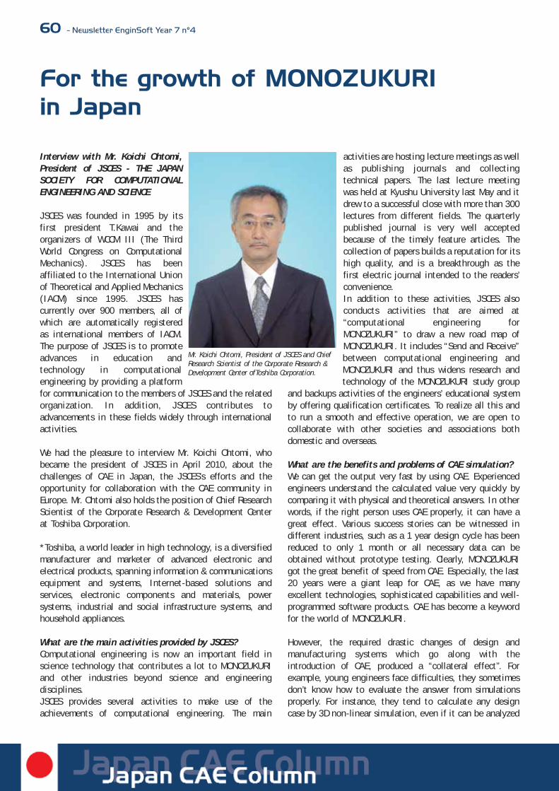
60 - Newsletter EnginSoft Year 7 n°4
Interview with Mr. Koichi Ohtomi,President of JSCES - THE JAPANSOCIETY FOR COMPUTATIONALENGINEERING AND SCIENCE
JSCES was founded in 1995 by itsfirst president T.Kawai and theorganizers of WCCM III (The ThirdWorld Congress on ComputationalMechanics). JSCES has beenaffiliated to the International Unionof Theoretical and Applied Mechanics(IACM) since 1995. JSCES hascurrently over 900 members, all ofwhich are automatically registeredas international members of IACM.The purpose of JSCES is to promoteadvances in education andtechnology in computationalengineering by providing a platformfor communication to the members of JSCES and the relatedorganization. In addition, JSCES contributes toadvancements in these fields widely through internationalactivities.
We had the pleasure to interview Mr. Koichi Ohtomi, whobecame the president of JSCES in April 2010, about thechallenges of CAE in Japan, the JSCES’s efforts and theopportunity for collaboration with the CAE community inEurope. Mr. Ohtomi also holds the position of Chief ResearchScientist of the Corporate Research & Development Centerat Toshiba Corporation.
*Toshiba, a world leader in high technology, is a diversifiedmanufacturer and marketer of advanced electronic andelectrical products, spanning information & communicationsequipment and systems, Internet-based solutions andservices, electronic components and materials, powersystems, industrial and social infrastructure systems, andhousehold appliances.
What are the main activities provided by JSCES?Computational engineering is now an important field inscience technology that contributes a lot to MONOZUKURIand other industries beyond science and engineeringdisciplines. JSCES provides several activities to make use of theachievements of computational engineering. The main
activities are hosting lecture meetings as wellas publishing journals and collectingtechnical papers. The last lecture meetingwas held at Kyushu University last May and itdrew to a successful close with more than 300lectures from different fields. The quarterlypublished journal is very well acceptedbecause of the timely feature articles. Thecollection of papers builds a reputation for itshigh quality, and is a breakthrough as thefirst electric journal intended to the readers’convenience. In addition to these activities, JSCES alsoconducts activities that are aimed at“computational engineering forMONOZUKURI” to draw a new road map ofMONOZUKURI. It includes “Send and Receive”between computational engineering andMONOZUKURI and thus widens research andtechnology of the MONOZUKURI study group
and backups activities of the engineers’ educational systemby offering qualification certificates. To realize all this andto run a smooth and effective operation, we are open tocollaborate with other societies and associations bothdomestic and overseas.
What are the benefits and problems of CAE simulation?We can get the output very fast by using CAE. Experiencedengineers understand the calculated value very quickly bycomparing it with physical and theoretical answers. In otherwords, if the right person uses CAE properly, it can have agreat effect. Various success stories can be witnessed indifferent industries, such as a 1 year design cycle has beenreduced to only 1 month or all necessary data can beobtained without prototype testing. Clearly, MONOZUKURIgot the great benefit of speed from CAE. Especially, the last20 years were a giant leap for CAE, as we have manyexcellent technologies, sophisticated capabilities and well-programmed software products. CAE has become a keywordfor the world of MONOZUKURI.
However, the required drastic changes of design andmanufacturing systems which go along with theintroduction of CAE, produced a “collateral effect”. Forexample, young engineers face difficulties, they sometimesdon’t know how to evaluate the answer from simulationsproperly. For instance, they tend to calculate any designcase by 3D non-linear simulation, even if it can be analyzed
For the growth of MONOZUKURI in Japan
Mr. Koichi Ohtomi, President of JSCES and ChiefResearch Scientist of the Corporate Research &Development Center ofToshiba Corporation.

Newsletter EnginSoft Year 7 n°4 - 61with a 2D linear simulation. All the necessary data andfunctions are prepared in the CAE software; this doesn’tchallenge the engineers to use their own thoughts,although theoretical thinking was indispensable until CAEsimulation became widely used some years ago. In the worstcases, users believe the simulation answer without a doubtas it does not seem right to think theoretically. Suchproblems may continue to occur until a new educationalsystem which focuses on CAE embedded MONOZUKURI hasbeen established.
What are the JSCES activities in the current CAEenvironment?Recently, we started the study and promotion of 1D-CAE.The 1D-CAE study group was established in JSCES, itorganizes regular workshops. Unlike typical 3D-CAE, 1D-CAEcan be implemented into the very early phase of the designcycle, which describes all the functions and phenomena ofboth the products’ hardware and software, and realizes theparameter study. It also includes nonphysical phenomena,such as consumers, society, economy and distribution. Ifthe engineers focus on this design concept at an early stageand then use 3D-CAE in the structural design, it will drivethe innovation of the design and also the human resourcedevelopment.
Furthermore, JSCES provides 2 more study groups to improvethe problem we have now. The first group is theMONOZUKURI study group which fosters the use of CAE forMONOZUKURI and discusses computational engineering fromthe viewpoint of MONOZUKURI. It holds the periodicalmeeting to exchange ideas and to provide a platform fordiscussion between manufacturing companies, academicassociations and vendors about, for example, simulationquality, verification & validation, 1D-CAE & 3D-CAE, andcomputational engineering and experimental engineering,etc. As the standard CAE software products used in Japan aremostly produced in the US and in European countries, theseprograms do not always suit the traditional Japanese designand manufacturing system called SURIAWASE (which meanscoordination). The study group’s aim is to find the right wayto use CAE in the Japanese MONOZUKURI culture.The second group is the HQC study group. HQC means High
Quality Computing. Although HPC (High PerformanceComputing) has been discussed for years, we need to thinkmore about “Quality” in the future. Maybe starting a routineto re-evaluate the simulation result inside the hardwarewould be a HQC. As far as CAE quality assurance isconcerned, our studies refer to ASME V&V and NAFEMS.
Are there any possibilities to collaborate with Europeanassociations?In 2010, I have visited the EnginSoft office in Padova, Italyin April and attended the TechNet Alliance Meeting inAachen, Germany, in November. These were uniqueopportunities to meet with CAE specialists from differentfields in Europe and to enrich both our understandings. Iwas impressed to see that CAE is on center stage, and thatboth users and vendors are keen to cooperate for a betteruse and enhancement of CAE software in Europe. Ifnecessary, even a small company makes their own CAEprogram by applying new technology.
I would like to introduce this positive attitude for CAE inEurope to Japan. Although the number of CAE softwarelicenses used in Japan is much higher than in most othercountries, the users often tend to be very passive. I thinkCAE users should be far more positive about improving their
own use of the software and the environment. With respectto CAE quality assurance, NAFEMS’ promotional activities forsafe and reliable CAE gives us many hints. For all thesereasons, we are hoping to collaborate with NAFEMS and alsoother European associations in various ways in the future.
*MONOZUKURI is being used in this article and in the futureinstead of MONODUKURI which was introduced before in pasteditions. Though both are used in Japan, the “Z” is morenatural in English-speaking countries. *MONOZUKURI is theJapanese expression for “production” or “manufacturing” inEnglish, but it is also used often in discussions aboutJapanese engineering spirit and traditional manufacturing.
For more information, please contact:Akiko Kondoh - [email protected]
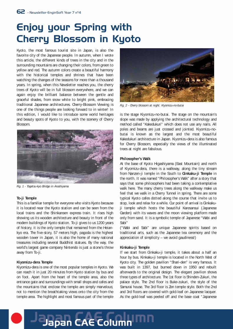
Kyoto, the most famous tourist site in Japan, is also thefavorite city of the Japanese people. In autumn, when I wrotethis article, the different kinds of trees in the city and in thesurrounding mountains are changing their colors, from green toyellow and red. The autumn colors create a beautiful harmonywith the historical temples and shrines that have beenwatching the changes of the seasons for more than a thousandyears. In spring, when this Newsletter reaches you, the cherrytrees of Kyoto will be in full blossom everywhere, and we canagain enjoy the brilliant balance between the gentle andgraceful shades, from snow white to bright pink, embracingtraditional Japanese architectures. Cherry-Blossom Viewing isone of the things people are looking forward to in winter! Inthis edition, I would like to introduce some world heritagesand beauty spots of Kyoto to you, with the scenery of CherryBlossom.
To-ji TempleThis is a familiar temple for everyone who visits Kyoto becauseit is located near the Kyoto station and can be seen from thelocal trains and the Shinkansen express train. It rises highshowing us its wooden architecture and beauty in front of themodern buildings of Kyoto station. To-ji gives to us 1200 yearsof history, it is the only temple that remained from the Heian-kyo era. The five-story, 57 meters high, pagoda is the highestwooden tower in Japan, it is also the home of many nationaltreasures including several Buddhist statues. By the way, theworld’s largest game company Nintendo is just a stone’s throwaway from To-ji.
Kiyomizu-dera TempleKiyomizu-dera is one of the most popular temples in Kyoto. Wecan reach it in just 20 minutes from Kyoto station by bus andon foot. Apart from the heart of the temple area, also theentrance gate and surroundings with small shops and cafes andthe mountains that enclose the temple are simply marvelous;not to mention the breathtaking views onto the city from thetemple area. The highlight and most famous part of the temple
is the stage Kiyomizu-no-butai. The stage on the mountain’sslope was made by applying the architectural technology andmethod called “Kakedukuri” which does not use any nails. Allpoles and beams are just crossed and jointed. Kiyomizu-no-butai is known as the largest and the most beautifulKakedukuri architecture in Japan. Kiyomizu-dera is also famousfor Cherry Blossom, especially the views of the illuminatedtrees at night are fabulous.
Philosopher’s WalkAt the base of Kyoto Higashiyama (East Mountain) and northof Kiyomizu-dera, there is a walkway, along the tiny streamfrom Nanzen-ji temple in the South to Ginkaku-ji Temple inthe north. It was named “Philosopher’s Walk” after a story thatsays that some philosophers had been taking a contemplativewalk here. The many cherry trees along the walkway make usfeel that we walk in a Cherry Tunnel in spring. There are sometypical Kyoto cafes dotted along the course that invite us tostop, look and relax for a while. Our point of arrival is Ginkaku-ji temple which hosts the beautiful Karesansui (JapaneseGarden) with its waves and the moon viewing platform madeonly from sand. It is a symbolic temple of Japanese “Wabi andSabi” (“Wabi and Sabi” are unique Japanese spirits based ontraditional arts, such as the Japanese tea ceremony and theappreciation of simplicity – we avoid gaudiness!)
Kinkaku-ji TempleIf we start from Ginkaku-ji temple, it takes about a half anhour by bus. Kinkaku-ji temple is located in the North West ofKyoto city. The golden pavilion “Shari-den” is very famous. Itwas built in 1397, but burned down in 1950 and rebuiltafterwards to the original design. The elegant pavilion showsthree types of architecture. The 1st floor is Shinden-Zukuri, thepalace style. The 2nd floor is Buke-zukuri, the style of theSamurai house. The 3rd floor is Zen temple style. Both the 2ndand 3rd floors are covered with gold-leaf on Japanese lacquer.As the gold-leaf was peeled off and the base coat “Japanese
62 - Newsletter EnginSoft Year 7 n°4
Enjoy your Spring with Cherry Blossom in Kyoto
Fig. 1 - Togetsu-kyo Bridge in Arashiyama
Fig. 2 - Cherry blossom at night: Kiyomizu-no-butai

Newsletter EnginSoft Year 7 n°4 - 63
black lacquer” got depleted by UV, another restoration wascompleted in 1980’. For this restoration, fivefold gold-leaf(0.45•0.55µm) was used while the gold-leaf of 0.1µm istypically used. The total gold-leaf on Shari-den is 200000sheets and 20kg. Also, 1.5 tons of Japanese lacquer have beenused for the base coating.
Ryoan-ji TempleAnother world heritage Ryoan-ji temple is located in the NorthWest of Kyoto city. It is famous for its Karesansui, the rockgarden style. This simple yet remarkable garden measures 30meters from the East to the West and 10 meters from the Southto the North. The walls are made from clay boiled in oil. In the
rectangular white sand garden, 15 stones are arranged by therule of 5,2,3,2,3. There are several legends about this design,that it shows some tigers crossing a river or a scene ofmountains and rivers in China. However, the truth is veiled inmystery. Still, this very simple rock garden is so calm and itsimperial section shows the Japanese Zen spirit superbly. AtCherry Blossom time, we will be moved by the views on whatappears like a painting of weeping cherry trees in thebackground of a peaceful garden.
ArashiyamaWe can enjoy a beautiful scenery on a half-hour train journeyfrom Ryoan-ji temple or also from Kyoto Station. Arashiyama isthe famous spot for Cherry Blossom in the western part ofKyoto. Everybody in Japan loves the landscape of different-colored mountain surfaces, the Katsura river and the delicateshape of Togetsu-kyo and of course, the famous traditionalarchitectures. Many years ago, the aristocracies and litterateurs
left the city to live a simple life there on the country. This iswhy we can still see and feel a lot of old Kyoto “flavor” in manyplaces, also in the old and small temples, shrines, holidayhouses and bamboo avenues. When you are tired after a day ofsightseeing, you may want to relax and taste Tofu Kaiseki(Japanese cuisine) in the Japanese style restaurantoverlooking Togetsu-kyo bridge.
If you visit Kyoto for the first time, I would recommend thatyou to spend 2 days to explore the above places. There aremany other sights near them and it would be much fun to lookout for Kyoto gifts and enjoy different food. Also, there isanother spot that I recommend to visit on a short trip: theworld heritage Byodo-in Temple in Uji. Uji is a half an hoursouth by train from Kyoto station, it is famous for high gradetea like Gyokuro and Maccha.
Byodo-in TempleByodo-in has a history of thousand years, it is relatively easyto discover because there are not many visitors usually.Although it is a very beautiful and unique place to visit, it issometimes not on the tourists’ routes simply because it is inthe southern area of Kyoto while most landmarks are locatedNorth of the city. The main hall called Phoenix Hall wasdesigned in the image of heaven, visitors sometimes feel likefloating on the pond in the garden. Its gorgeous views are verydifferent from other temples. Phoenix Hall consists of 4 partsof the center hall and right, left and back transepts. We can seethe Amitabha Tathagata Statue through the circle window inthe front center of the main hall. The Byodo-in Phoenix hallhas been drawn on the 10 Yen coin and the Phoenix displayedon the roof is shown on the 10,000 Yen banknote.
I lived near Kyoto during my college days and walked in thestreets of Kyoto city very often. With this short article, Iwanted to introduce to you some of the beautiful and famoussights that I would recommend to explore when you come toKyoto for the first time. Other articles about Kyoto will appearin the Japan Columns of the next editions, they will tell youmore about Japan’s cultural treasure house!
Akiko KondohConsultant for EnginSoft in Japan
Fig. 3 - Shari-den in Kinkaku-ji Temple
Fig. 4 - Rock garden in Ryoan-ji Temple
Fig. 5 - Byodo-in Phoenix Hall
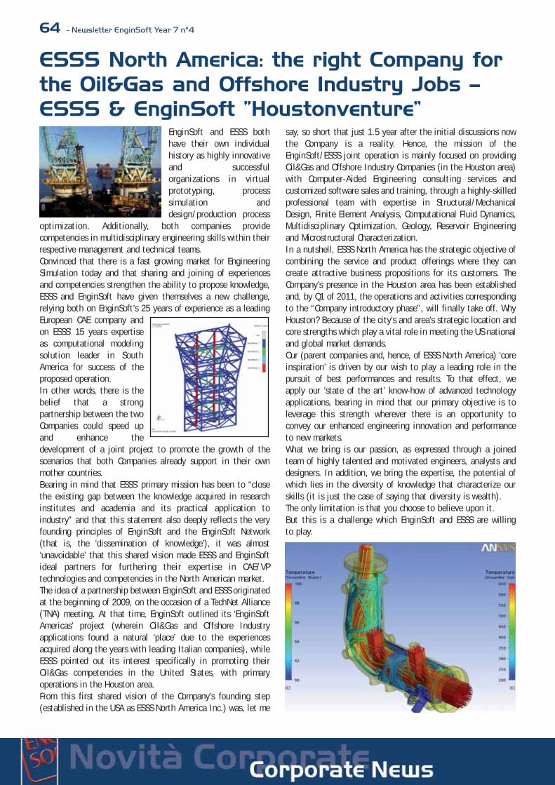
64 - Newsletter EnginSoft Year 7 n°4
EnginSoft and ESSS bothhave their own individualhistory as highly innovativeand successfulorganizations in virtualprototyping, processsimulation anddesign/production process
optimization. Additionally, both companies providecompetencies in multidisciplinary engineering skills within theirrespective management and technical teams.Convinced that there is a fast growing market for EngineeringSimulation today and that sharing and joining of experiencesand competencies strengthen the ability to propose knowledge,ESSS and EnginSoft have given themselves a new challenge,relying both on EnginSoft’s 25 years of experience as a leadingEuropean CAE company andon ESSS’ 15 years expertiseas computational modelingsolution leader in SouthAmerica for success of theproposed operation.In other words, there is thebelief that a strongpartnership between the twoCompanies could speed upand enhance thedevelopment of a joint project to promote the growth of thescenarios that both Companies already support in their ownmother countries.Bearing in mind that ESSS’ primary mission has been to “closethe existing gap between the knowledge acquired in researchinstitutes and academia and its practical application toindustry” and that this statement also deeply reflects the veryfounding principles of EnginSoft and the EnginSoft Network(that is, the ‘dissemination of knowledge’), it was almost‘unavoidable’ that this shared vision made ESSS and EnginSoftideal partners for furthering their expertise in CAE/VPtechnologies and competencies in the North American market.The idea of a partnership between EnginSoft and ESSS originatedat the beginning of 2009, on the occasion of a TechNet Alliance(TNA) meeting. At that time, EnginSoft outlined its ‘EnginSoftAmericas’ project (wherein Oil&Gas and Offshore Industryapplications found a natural ‘place’ due to the experiencesacquired along the years with leading Italian companies), whileESSS pointed out its interest specifically in promoting theirOil&Gas competencies in the United States, with primaryoperations in the Houston area. From this first shared vision of the Company’s founding step(established in the USA as ESSS North America Inc.) was, let me
say, so short that just 1.5 year after the initial discussions nowthe Company is a reality. Hence, the mission of theEnginSoft/ESSS joint operation is mainly focused on providingOil&Gas and Offshore Industry Companies (in the Houston area)with Computer-Aided Engineering consulting services andcustomized software sales and training, through a highly-skilledprofessional team with expertise in Structural/MechanicalDesign, Finite Element Analysis, Computational Fluid Dynamics,Multidisciplinary Optimization, Geology, Reservoir Engineeringand Microstructural Characterization.In a nutshell, ESSS North America has the strategic objective ofcombining the service and product offerings where they cancreate attractive business propositions for its customers. TheCompany’s presence in the Houston area has been establishedand, by Q1 of 2011, the operations and activities correspondingto the “Company introductory phase”, will finally take off. WhyHouston? Because of the city’s and area’s strategic location andcore strengths which play a vital role in meeting the US nationaland global market demands.Our (parent companies and, hence, of ESSS North America) ‘coreinspiration’ is driven by our wish to play a leading role in thepursuit of best performances and results. To that effect, weapply our ‘state of the art’ know-how of advanced technologyapplications, bearing in mind that our primary objective is toleverage this strength wherever there is an opportunity toconvey our enhanced engineering innovation and performanceto new markets. What we bring is our passion, as expressed through a joinedteam of highly talented and motivated engineers, analysts anddesigners. In addition, we bring the expertise, the potential ofwhich lies in the diversity of knowledge that characterize ourskills (it is just the case of saying that diversity is wealth).The only limitation is that you choose to believe upon it.But this is a challenge which EnginSoft and ESSS are willing to play.
ESSS North America: the right Company forthe Oil&Gas and Offshore Industry Jobs –ESSS & EnginSoft “Houstonventure”
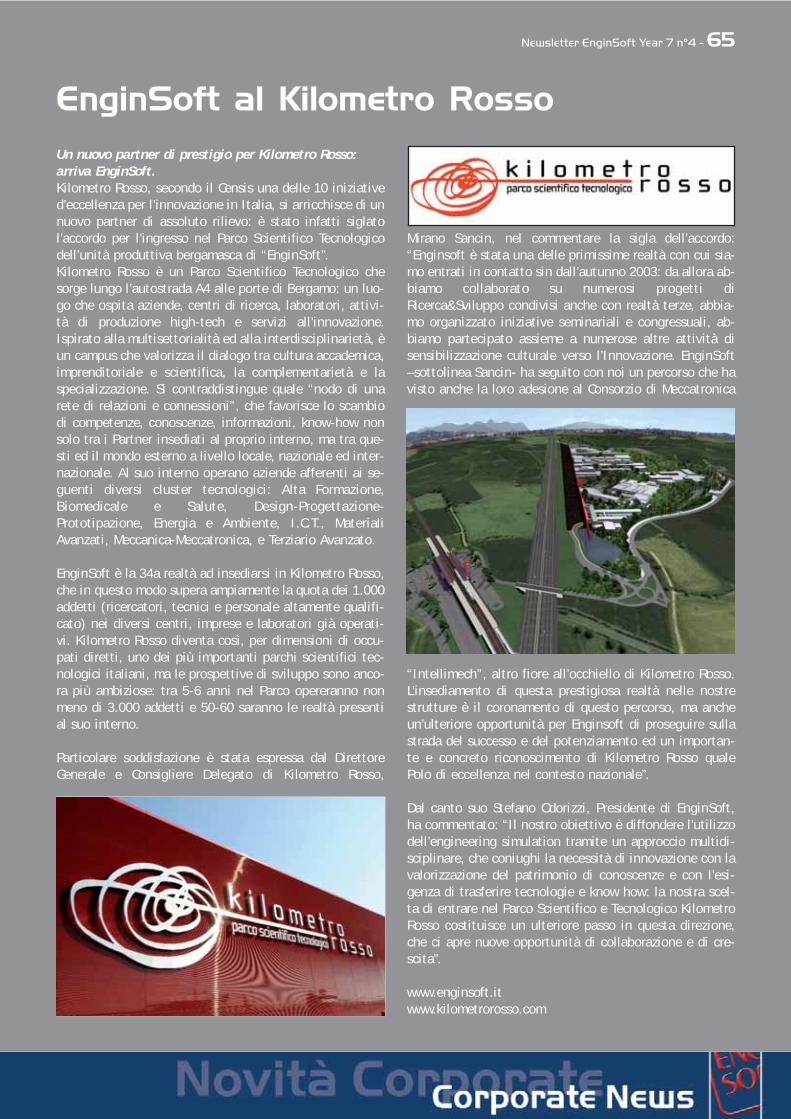
Newsletter EnginSoft Year 7 n°4 - 65
Un nuovo partner di prestigio per Kilometro Rosso: arriva EnginSoft.Kilometro Rosso, secondo il Censis una delle 10 iniziatived’eccellenza per l’innovazione in Italia, si arricchisce di unnuovo partner di assoluto rilievo: è stato infatti siglatol’accordo per l’ingresso nel Parco Scientifico Tecnologicodell’unità produttiva bergamasca di “EnginSoft”.Kilometro Rosso è un Parco Scientifico Tecnologico chesorge lungo l’autostrada A4 alle porte di Bergamo: un luo-go che ospita aziende, centri di ricerca, laboratori, attivi-tà di produzione high-tech e servizi all’innovazione.Ispirato alla multisettorialità ed alla interdisciplinarietà, èun campus che valorizza il dialogo tra cultura accademica,imprenditoriale e scientifica, la complementarietà e laspecializzazione. Si contraddistingue quale “nodo di unarete di relazioni e connessioni”, che favorisce lo scambiodi competenze, conoscenze, informazioni, know-how nonsolo tra i Partner insediati al proprio interno, ma tra que-sti ed il mondo esterno a livello locale, nazionale ed inter-nazionale. Al suo interno operano aziende afferenti ai se-guenti diversi cluster tecnologici: Alta Formazione,Biomedicale e Salute, Design-Progettazione-Prototipazione, Energia e Ambiente, I.C.T., MaterialiAvanzati, Meccanica-Meccatronica, e Terziario Avanzato.
EnginSoft è la 34a realtà ad insediarsi in Kilometro Rosso,che in questo modo supera ampiamente la quota dei 1.000addetti (ricercatori, tecnici e personale altamente qualifi-cato) nei diversi centri, imprese e laboratori già operati-vi. Kilometro Rosso diventa così, per dimensioni di occu-pati diretti, uno dei più importanti parchi scientifici tec-nologici italiani, ma le prospettive di sviluppo sono anco-ra più ambiziose: tra 5-6 anni nel Parco opereranno nonmeno di 3.000 addetti e 50-60 saranno le realtà presential suo interno.
Particolare soddisfazione è stata espressa dal DirettoreGenerale e Consigliere Delegato di Kilometro Rosso,
Mirano Sancin, nel commentare la sigla dell’accordo:“Enginsoft è stata una delle primissime realtà con cui sia-mo entrati in contatto sin dall’autunno 2003: da allora ab-biamo collaborato su numerosi progetti diRicerca&Sviluppo condivisi anche con realtà terze, abbia-mo organizzato iniziative seminariali e congressuali, ab-biamo partecipato assieme a numerose altre attività disensibilizzazione culturale verso l’Innovazione. EnginSoft–sottolinea Sancin- ha seguito con noi un percorso che havisto anche la loro adesione al Consorzio di Meccatronica
“Intellimech”, altro fiore all’occhiello di Kilometro Rosso.L’insediamento di questa prestigiosa realtà nelle nostrestrutture è il coronamento di questo percorso, ma ancheun’ulteriore opportunità per Enginsoft di proseguire sullastrada del successo e del potenziamento ed un importan-te e concreto riconoscimento di Kilometro Rosso qualePolo di eccellenza nel contesto nazionale”.
Dal canto suo Stefano Odorizzi, Presidente di EnginSoft,ha commentato: “Il nostro obiettivo è diffondere l’utilizzodell’engineering simulation tramite un approccio multidi-sciplinare, che coniughi la necessità di innovazione con lavalorizzazione del patrimonio di conoscenze e con l’esi-genza di trasferire tecnologie e know how: la nostra scel-ta di entrare nel Parco Scientifico e Tecnologico KilometroRosso costituisce un ulteriore passo in questa direzione,che ci apre nuove opportunità di collaborazione e di cre-scita”.
www.enginsoft.itwww.kilometrorosso.com
EnginSoft al Kilometro Rosso

66 - Newsletter EnginSoft Year 7 n°4
ITALY
EnginSoft is pleased to announce the next Seminars andWebinars. For more information on the next 2011 events,please contact: [email protected]
SWEDEN
2011 Training Courses on modeFRONTIER - Drive yourdesigns from good to GREAT.
EnginSoft Nordic offices in Lund, Sweden. The TrainingCourses are focused on optimization, both multi- andsingle-objective, process automation and interpretation ofresults. Participants will learn different optimizationstrategies in order to complete a project within a specifiedtime and simulation budget. Other topics, such as design ofexperiments, metamodeling and robust design areintroduced as well. The two day training consists of a mixof theoretical sessions and workshops: 10-11 January, 1-2February, 2-3 March, 7-8 April, 2-3 May, 7-8 June, 11-12August, 5-6 September, 4-5 October, 2-3 November, 1-2December. For more information and to register, please contactEnginSoft Nordic, [email protected]
UKThe workshops are designed to give delegates a goodappreciation of the functionality, application and benefitsof modeFRONTIER. The workshops include an informal blendof presentation plus ‘hands-on’ examples with the objectiveof enabling delegates to be confident to evaluatemodeFRONTIER for their applications using a trial license atno cost.
modeFRONTIER Workshops at Warwick Digital Lab10.00 to 15:30 at the International Digital Laboratory,University of Warwick: 10 March, 12 May, 20 July, 14September, 22 November.
modeFRONTIER Workshops with InfoWorks CS at WarwickDigital Lab. 10.00 to 15:30 at the International DigitalLaboratory, University of Warwick8 February, 26 May, 9 November.Please register for free on www.enginsoft-uk.com
Training Days at International Digital Lab, WarwickUniversity 18-19 May, 6-7 September.
For more information and to register, please visitwww.enginsoft-uk.com. Contact: Bipin Patel, [email protected]
FRANCE
EnginSoft France 2011 Journées porte ouverte dans noslocaux à Paris et dans d’autres villes de France, encollaboration avec nos partenaires. Prochaine événement:Journées de présentation modeFRONTIER Pour plus d'information visitez: www.enginsoft-fr.com, contactez: [email protected]
GERMANY
Please stay tuned to www.enginsoft-de.comContact [email protected] for more information.modeFRONTIER Seminars 2011. EnginSoft GmbH, Frankfurtam Main. Attend our regular Webinars and Seminars to learnmore on how design optimization with modeFRONTIER canenhance your product development processes.
Seminars Process Product Integration. EnginSoft GmbH,Frankfurt am Main. How to innovate and improve yourproduction processes. Seminars hosted by EnginSoft Germanyand EnginSoft Italy.
EnginSoft Event Calendar
TechNet Alliance Fall Meeting 2010
The recent TechNet Alliance Fall Meeting which was held on5th and 6th November at the Pullman Aachen Quellenhof,welcomed over 80 Members of the Alliance and invitedguests to a most interesting program of presentations anddiscussions about CAE.
CADFEM GmbH presented “Electro-thermal simulation forEV/HEV applications”, a captivating future-oriented topicwhich we are proud to feature in this Newsletter.EnginSoft S.p.A. used the Meeting as an opportunity toinform the audience of their expertise and services in thearea of simulation of Metal Processing.
About the TechNet Alliance:The TechNet Alliance is aunique consortium in theComputer Aided Engineering(CAE) or Simulation BasedEngineering Sciencesindustry. It is comprised of a large network of engineeringsolution providers- dedicated to the application,development, training, support and marketing of CAE best-of-class software.
For more information, please visit: www.technet-alliance.com or contact: Mrs KristinSchuhegger, [email protected]

Newsletter EnginSoft Year 7 n°4 - 67SPAIN
Programa de cursos de modeFRONTIER and other localevents. Please contact our partner, APERIO Tecnología:[email protected]. Stay tuned to: www.aperiotec.es
5-8 June - IDDRG 2011 International Conference. Bilbao(País Vasco). This year, apart from the stamping, materialscharacterization, numerical simulation, tooling and UHSSsubjects normally covered, the IDDRG conference organizerswould like to frame the conference considering a globalconcern, which is currently a target not only for industrybut also for consumers, political leaders and businessmanagers: Sustainability.For more information, please visit: http://www.iddrg2011.eu/
GREECE
9 May - 5th PhilonNet CAE Conference. AthensIf you would like to present your work with ANSYS(including CFX, Fluent and Ansoft products), ANYBODY,DIFFPACK, ESACOMP, eta/DYNAFORM, eta/VPG,FLOWMASTER, FTI, LS-DYNA, modeFRONTIER, MOLDFLOW,SIMPLEWARE or ADVANTEDGE please send your abstract to:[email protected] more information, please visit: www.philonnet.gr
USA1 February - Optimization Day. Stanford University. Aninvitation-only Forum to Discuss New Research Directionsand Industrial Applications. Organized by Enginsoft and theTFSA Program. Optimization Has Become an IndispensableInstrument in Engineering Practice, and CommercialPackages have Achieved Wide Popularity. Applications rangefrom Rapid Product Development to Web searching, fromSophisticated Multidisciplinary Analysis to Robust DesignUnder Uncertainty. What are the Remaining Barriers forOptimization Algorithms? How are Present ComputationalResources Changing the Paradigm of Engineering Design?Are Current Optimization Methods Sufficient to DriveDecision- Making? Presentation by Recognized Leaders inthe Field will Provide an Opportunity to Discuss theOpportunities and Frontiers of Optimization Technology forReal-World Applications
EUROPE, VARIOUS LOCATIONS
modeFRONTIER Academic Training Please note: These Courses are for Academic users only. TheCourses provide Academic Specialists with the fastest routeto being fully proficient and productive in the use ofmodeFRONTIER for their research activities. The coursescombine modeFRONTIER Fundamentals and AdvancedOptimization Techniques. For more information, please contact Rita Podzuna,[email protected]
To meet with EnginSoft at any of the above events, pleasecontact us at: [email protected]
SEMINARIO: Integrare Strumentie Metodi di Progettazione eSimulazione Un grande successo per l’incontro organizzato il 23 no-vembre scorso presso lo Sheraton Hotel in RomaCommenti positivi e soddisfazione generale per il seminarioproposto e organizzato da EnginSoft in collaborazione e sot-to l’egida dell’AIAD il 23 novembre 2010 presso lo SheratonGolf Parco de' Medici Hotel & Resort in Roma, evento che harichiamato l’attenzione di numerosi partecipanti e ha riuni-to rappresentanti di molte realtà aziendali che da anni uti-lizzano la simulazione in ambito aerospaziale. Integrare Strumenti e Metodi di Progettazione e Simulazione,questo il titolo del Seminario, è un tema di grande attualitàsia per chi opera a livello tecnico nell'industria, sia per chiha responsabilità manageriali ed organizzative.L'attuale era industriale del settore aerospaziale è vibrante dinuove opportunità sia tecnologiche che commerciali alla lu-ce del particolare momento dell’economia mondiale.
In tale contesto economico-finanziario, il successo delleaziende del settore può essere fortemente influenzato daicambiamenti che sapranno mettere in atto in relazione alleloro metodologie progettuali, ad esempio arricchendo le pro-prie soluzioni di design in funzione di specifiche tecnologi-che afferenti a tematiche diversificate (meccaniche, elettro-niche, termiche, aerodinamiche e di processo), così da riu-scire a interpretare correttamente le diverse richieste delmercato. Scopo dell’incontro era dunque evidenziare l’impor-tanza e la declinazione delle opportunità offerte dalla simu-lazione virtuale, in funzione delle esigenze di un mercatomoderno e sempre più competitivo. A dimostrazione di quan-to sopra, EnginSoft ha voluto portare in campo la propriaesperienza e competenza, mettendo a disposizione dei par-tecipanti un bagaglio di conoscenze acquisito negli anni, at-traverso l’utilizzo delle tecnologie più avanzate nella quoti-dianità dei compiti aziendali. Il seminario, che ha riguarda-to alcune applicazioni in ambito strutturale, elettronico,fluidodinamico e per il design di sistemi con applicazioni dimodeFRONTIER®, ha visto relatori e ingegneri specializzatiEnginSoft che si sono alternati durante l’evento per propor-re e illustrare attraverso casi applicativi alcuni esempi in am-bito aerospaziale con modelli specifici nell’uso dei metodi disimulazione applicati ad ambiti multidisciplinari. Gli esempiillustrati hanno fatto riferimento a significative esperienzetra cui quella Aerosekur. Il confronto è stato un successo,così proficuo e vitale tanto che EnginSoft si ripropone di or-ganizzare in futuro un nuovo incontro sul tema Aerospace.

Key partner in Design Process Innovation
NUOVO LIBRETTO - NEW PUBBLICATION
SOFTWARE TRAINING COURSES 2011
CORSI DI ADDESTRAMENTO SOFTWARE 2011
Training Center EnginSoft
Sono stati inoltre rivisti ed aggiornati i corsi relativi a tutti gli altrisoftware sostenuti da EnginSoft per adeguarli allo stato attualedelle relative distribuzioni.
Si segnala infine l'introduzione del nuovo corso SCILAB aperto atutti coloro che intendono avvicinarsi ad uno strumento opensource per la risoluzione di problemi di simulazione numerica adampio raggio.
Dal punto di vista organizzativo nel 2011 tutte le cinque sediEnginSoft saranno impegnate nella formazione, dando lapossibilità agli utenti di scegliere la location a loro più convenientein termini di vicinanza geografica alla propria società.
Tutto questo a riprova dell'impegno nella formazione che, perEnginSoft, è e rimane un punto fondamentale della politicaaziendale, un impegno costante verso l'eccellenza, un servizio perfare crescere i suoi clienti e, se lo desiderano, crescere con loro.
EnginSoft è la società italiana di maggior consistenza e tradizionenel settore del CAE ove, grazie alla multidisciplinarietà dellecompetenze, è in grado di proporsi come partner unico per leaziende.L'attività di formazione rappresenta da sempre uno dei tremaggiori obiettivi di EnginSoft accanto alla distribuzione edassistenza del software ed ai servizi di consulenza eprogettazione.Per ciascuno dei possibili livelli cui la richiesta di formazione puòporsi (quella del progettista, dello specialista o del responsabile diprogettazione), EnginSoft mette a disposizione la propriaesperienza per accelerare i tempi del completo apprendimentodegli strumenti necessari con una gamma completa di corsidifferenziati sia per livello (di base o specialistico), che per profiloprofessionale dei destinatari (progettisti, neofiti od analistiesperti).
La finalità è sempre di tipo pratico: condurre rapidamenteall'utilizzo corretto del codice, sviluppando nell'utente la capacitàdi gestire analisi complesse attraverso l'uso consapevole delcodice di calcolo. Per questo motivo ogni corso è diviso in sessionidedicate alla presentazione degli argomenti teorici alternate asessioni 'hands on', in cui i partecipanti sono invitati ad utilizzareattivamente il codice di calcolo eseguendo applicazioni guidate odabbozzando, con i suggerimenti del trainer, soluzioni per iproblemi di proprio interesse e discutendone impostazioni erisultati.
Anche per il 2011 EnginSoft propone una serie completa di corsiche coprono le necessità di formazione all'uso dei diversi softwarecommercializzati.Le novità proposte confermano che l'idea che EnginSoft ha dellaformazione non è una realtà statica che si ripropone uguale a sestessa di anno in anno, ma è un divenire, guidato dall'esperienzaaccumulata negli anni, dall'evoluzione del software e dalleesigenze delle società che si affidano a noi per la formazione delproprio personale. In tale contesto EnginSoft organizza e sviluppaanche attività didattiche attraverso un programma formativopersonalizzato, soluzioni di progettati inrelazione alle necessità e alle specifiche esigenze aziendali delcommittente.
L'offerta dei corsiANSYS si adegua all'evoluzione del software edalle caratteristiche della recentissima versione 13:• in campo elettromagnetico vengono introdotti tre corsi specifici:
ANSOFT MAXWELL 2D, ANSOFT MAXWELL 3D e ANSOFTSIMPLORER;
• in campo fluidodinamico è da rimarcare l'introduzione, accantoai corsi tradizionalmente erogati, del corso ANSYS ICEPAK e dicorsi specifici per il solutore SCULPTOR.
Corsi su Misura
www.enginsoft.it/corsi