moving towards a more electric aircraft - semantic scholar · moving towards a more electric...
TRANSCRIPT

Moving Towards a More Electric Aircraft
J.A. Rosero, J.A. Ortega, E. Aldabas, & L. Romeral
ABSTRACT
The latest advances in electric and electronic aircrafttechnologies from the point of view of an "all-elect~ric"aircraft are presented herein. Specifically, we describe theconcept of a "More Electric Aircraft" (MEA), whichinvolves removing the need for on-engine hydraulicpower generation and bleed air off-takes, and theincreasing use of power electronics in thestarter/generation system of the main engine. Removal ofthe engine hydraulic pumps requires fully-operativeelectrical power actuators and mastery of the flightcontrol architecture. The paper presents a generaloverview of the electrical power generation system andelectric drives for the MIEA, with special regard to theflight controls. Some discussion regarding theinterconnection of nodes and safety of buses and protocolsin distributed systems is also presented.
INTRODUCTION
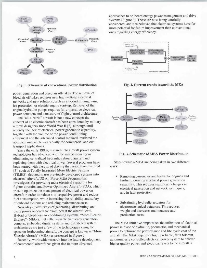
Conventional aircraft architectures used for civil aircraftembody a combination of systems dependent on mechanical,hydraulic, pneumatic, and electrical sources. The resultingconventional equipment is the product of decades ofdevelopment by system suppliers.
In a conventional architecture (Figure 1 is a basicschematic) fuel is converted into power by the engines. Mostof this power is used as propulsive power to move theaircraft. The remainder is converted into four main forms ofnon-propulsive power [1]:
Pneumatic power, obtained from the engines'high-pressure compressors. This kind of energyis conventionally used to power the
Refereeing of this work was handled by L.M. Kaplan.
Manuscript received November 30, 2005; revised May 23. 2006.
Author's Currnt Address;LA. Rosero, J.A. Ortega, E. Aldabas, & L. Romeral
0885/8985/07/ USA $25.00 0 2007 IEEE
IEEE A&E SYSTEMS MAGAZINE, MARCH 2007
Environmental Control System (ECS) andsupply hot air for Wing Anti-Icing (WAI)systems. Its drawbacks are low efficiency and adifficulty in detecting leaks.
" Mechanical power, which is transferred (bymeans of the mechanical gearboxes) from theengines to central hydraulic pumps, to localpumps for engine equipment and othermechanically driven subsystems, and to themain electrical generator.
" Hydraulic power, which is transferred from thecentral hydraulic pump to the actuation systemsfor primary and secondary flight control; tolanding gear for deployment, retraction, andbraking; to engine actuation; and to numerousancillary systems. Hydraulic systems have ahigh power density and are very robust. Theirdrawbacks are a heavy and inflexibleinfrastructure (piping) and the potential leakageof dangerous and corrosive fluids.
" Electrical power, which is obtained from themain generator in order to power the avionics,cabin and aircraft lighting, galleys, and othercommercial loads (such as entertainmentsystems). Electrical power does not require aheavy infrastructure and is very flexible. Itsmain drawbacks are that conventionally it has alower power density than hydraulic power, andresults in a higher risk of fire (in the case of ashort circuit).
Each system has become more and more complex, andinteractions between different pieces of equipment reduce theefficiency of the whole system. A simple leak in thepneumatic or hydraulic system may lead to the outage ofevery user of that network, resulting in a grounded aircraftand flight delays. The leak is generally difficult to locate andonce located it cannot be accessed easily.
The trend is to move towards "all-electric" aircraft, whichmeans that all power off-takes from the aircraft are electricalin nature, thus removing the need for on-engine hydraulic
3
Fligh~t
HydraulicPower
Mechanical kaloNPower r
Elcrc ElectricalGeeao, Power
Ice Protection
PneumaticComfpressor Power
ECS
approaches to on-board energy power management and drivesystems (Figure 3). These are now being carefullyconsidered, and it is believed that electrical systems have farmore potential for future improvement than conventionalones regarding energy efficiency.
fIot __, Ulvt o
Fig. 1. Schematic of conventional power distribution
power generation and bleed air off-takes. The removal ofbleed air off-takes requires new high-voltage electricalnetworks and new solutions, such as air-conditioning, wingice protection, or electric engine start-up. Removal of theengine hydraulic pumps requires fully-operative electricalpower actuators and a mastery of flight control architecture.
The "all-electric" aircraft is not a new concept: theconcept of an electric aircraft has been considered by militaryaircraft designers since World War 11 [2], although untilrecently the lack of electrical power generation capability,together with the volume of the power conditioningequipment and the advanced control required, rendered theapproach unfeasible - especially for commercial and civiltransport applications.
Since the early 1990s, research into aircraft power systemtechnologies has advanced with the aim of reducing oreliminating centralized hydraulics aboard aircraft andreplacing them with electrical power. Several programs havebeen started with the aim of driving the research on this field[3], such as Totally Integrated More Electric Systems(TIMES), devoted to use previously developed systems intoelectrical aircraft, US Air Force MEA Program thatinvestigates for providing more electrical capability forfighter aircrafts, and Power Optimized Aircraft (POA), whichtries to optimize the management of electrical power onaircraft in order to reduce non-propulsive power and reducefuel consumption, while increasing the reliability and safetyof onboard systems and reducing maintenance costs.
Nowadays, novel ways of generating. distributing, andusing power onboard are examined at the aircraft level.Hybrid or bleed-less air conditioning systems, "More ElectricEngines" (MEEs), fuel cells, variable frequency generators,complex embedded digital systems and distributed systemarchitectures are just a few of the technologies vying forspace on forthcoming aircraft; the concept is known as "MoreElectric Aircraft" (MEA) as presented in Figure 2.
Recently, worldwide research into the future developmentof commercial aircraft has given rise to more advanced
Fig. 2. Current trends toward the MEA
Power ft
Au
Compressor P a
Fig. 3. Schematic of MEA Power Distribution
Steps toward a MEA are being taken in two different
ways:
" Removing current air and hydraulic engines andfurther increasing electrical power generationcapability. This requires significant changes inelectrical generation and network techniques,and in fault protection.
* Substituting hydraulic actuators forelectromechanical actuators. This reducesweight and decreases maintenance andproduction costs.
The MEA initiative emphasizes the utilization of electricalpower in place of hydraulic, pneumatic, and mechanicalpower to optimize the performance and life cycle cost of theaircraft. The MEA requires a highly reliable, fault tolerant,autonomously controlled electrical power system to deliverhigher quality power and electrical levels to the aircraft's
4 IEEE A&E SYSTEMS MAGAZINE, MARCH 2007
Loa _J s
111111111111010. Enginesyýpenis
OMMOMMM+ Ice Protection
- I EC 8
4
CentralHydraulic
Pump
Flightcontrols

loads. Also, reliable high integration and safety of theelectrical power system leads to the use of distributedgeneration and control architecture.
The advantages of More Electric systems are not confinedto aircraft. Other transport systems, such as marinepropulsion, are also moving in this direction [4].
The next sections briefly discuss a general overview of theelectrical power generation system and electric drives on theMEA, especially with regard to the flight controls. A briefintroduction to the safety aspects of the flight controls hasalso been included.
ELECTRONIC POWER SYSTEMS
The first factor to take into account is the large amount ofpower electronics for power conversions and power usersthat MBA will involve: at least 1.6 MW for a next-generation300 pax aircraft. The development of efficient and securepower electronics technologies is a great challenge. However,not only are power electronics necessary, but also efficientcontrol of the electronics must be developed.
One major evolutionary technological advance that hascontributed greatly to the feasibility of an electric aircraftnon-propulsive power system has been the development ofreliable, solid-state, high power-density, power-relatedelectronics. Generator power control units, inverters,converters, and motor controllers consist of state-of-the-artsilicon-based power semiconductor switching devices thatinclude integrated gate bipolar transistors (IGBTs). It isexpected that advanced composition, high-performancemulti-layer ceramic capacitors will dramatically improve thepower density of future inverters, converters, and motorcontrollers. Improved, high-efficiency electric circuittopologies are also the subject of on-going research.
Some of the higher power level equipment is activelycooled through the use of oil circulation or forced airconvection. The extent of the use of active, fluid-basedcooling systems is extremely application-specific and is yetto be determined. Lightweight, simplified, passive(non-pumped fluid-based) thermal management techniquesare also a focus of research and will be used, whereverfeasible, to maintain high reliability.
Power Distribution and Management Systems (PDMS)provide fully automatic monitoring, control, protection, andswitching of aircraft electrical loads under normal andemergency conditions with load management, includingautomatic load shedding and restoration, to make best use ofavailable power. These systems comprise the Primary PowerBuses, located close to the generators, with high powercontactors and circuit breakers, and the Secondary PowerDistribution Buses, located in the avionics bay, whichprovide the monitoring and control of the system, and containsome same circuit breakers and remote power switches.
The use of programmable solid-state devices andswitching power devices in place of traditionalelectromechanical circuit breaker technology providesbenefits to the aircraft in terms of load management, fault
isolation, diagnostic health monitoring, and improvedflexibility to accommodate modifications and systemupgrades.
With these advancing technologies, it will be feasible touse high power-density electrical power components to drivethe majority of aircraft subsystems. These will become easierto maintain (supported by less equipment and manpower),more durable, lower in cost, and higher in performance.
The engine primarily provides thrust, but it also producesall other power (Figure 1). In a MEA, current engineaccessories that derive power form gearbox mounted pumpswill be replaced with electronically-driven electricalmachines. Vibration resistance, electromagneticcompatibility, and size constraints are key design challengersof embedding electrical machines into the engine. Theintegration into a harsh environment of engine off-takes foraircraft system needs without significantly affecting engineperformance is also a difficult task.
By deleting air off-takes, virtually the only requirementthe engines have to satisfy is to provide electrical power.Whilst the hot-air bleed ducts and the pre-cooler areremoved, several other integration issues arise, such asgenerator thermal management, mechanical integration, newelectric starting requirements, and electrical powerconversion, (whether the chosen solution is a conventionalgearbox-mounted generator or an embeddedpower-optimized generator).
Conceptually, electrical power for an MEA would beproduced by a starter/generator directly driven by the gasgenerator spool of the main engine. Power is transferred outof the engine through wires that feed into a fault-tolerantelectrical network to drive the aircraft subsystems. Electronicpower converters would transform the electrical power andno accessory gearboxes would be necessary. Elimination ofgearing and associated gear separation forces enhances theuse of advanced magnetic bearing systems [5]1, which couldbe integrated into the internal starter/generator for both themain engine and auxiliary power units.
For many years, electrical power for aerospaceapplications has been generated using a variable ratiogearbox-mounted wound-field synchronous machine toobtain a three-phase 115 V AC system at a constantfrequency of 400 Hz. This machine is known as a ConstantFrequency Integrated Drive Generator (IDG), and today it isstill the most commonly used. However, operatingexperiences under the new requirements of lower cost,increased reliability, easier maintenance, and higheroperating speed and temperatures have shown that areplacement for the gearbox using power electronics hasobvious advantages. A high quality three-phase AC-DCconversion plus subsequent DC-AC conversion is one of thesteps involved in achieving these objectives. The resultingsystem is known as variable speed constant frequency(VSCF) system, and it results in promising technology thatmeets these requirements.
Figure 4 shows a typical block diagram of a VSCF system.In the motoring mode, the constant frequency system
IEEE A&E SYSTEMS MAGAZINE, MARCH 20075 5

supplies the machine through the power converter, and thesystem acts as a starter for the aircraft engine. In thegenerating mode, the main engine moves the machine,providing electrical power at a variable frequency which istransformed into a constant frequency by the powerconverter.
The bidirectional power converter can be built using a DClink in a back-to-back topology - a mature technology in usein civil aircraft (Boeing, MacDouglas, etc.) or by using adirect AC-to-AC converter. This is a new technology that isincreasingly used in military fighter aircraft.
The matrix converter [6] is a clear alternative to any otherAC-to-AC converter for aerospace applications. Theconverter consists of nine bi-directional switches arranged asthree sets of three so that any of the three input phases can beconnected to any of the three output lines. The switches arethen controlled in such a way that the average output voltagesare a three-phase set of sinusoids; of the required frequencyand magnitude. Some of the advantages of the converter thatmake it a promising technology for the near future are asfollows:
" A higher power ratio with a lower size andweight.
" Unity power factor control.
" It is free from bulky reactive components
(especially large electrolytic capacitors).
Electromagnetic interferences due to large currents andvoltages high frequency switching are the main disadvantageof power electronics supplying actuation systems. Theseinterferences can be alleviated by reducing the length ofelectrical cables supplying power and even more byintegrating the matrix converter into de motor-actuatorsystem. Moreover, the ability of matrix converter to supplyalmost sinusoidal currents helps to reduce these interferencesas well.
Application of higher voltages is also investigated, whichallows reducing the weight for the power used. 230/400 VAC400 Hz could be relevant for some electrical subsystemsbecause of its lighter weight generator system. 270 VDC iscommonly used as DC link bus voltage, whereas the motorcontrollers can use even higher level, 540 VDC.
Another solution to generate electrical power for theaircraft consists in variable-frequency (VF) powergeneration, which allows designers to discard the complexand difficult-to-maintain equipment necessary to convertvariable-speed mechanical power produced by the engines toconstant-frequency electrical power traditionally used byaircraft systems. By this way, variable-frequency powergeneration increases reliability of the whole system. Ofcourse, aircraft's systems such as fuel and hydraulic pumpsand EHA/EMA actuators have to be designed to becompatible with VF generation and distribution.
Yelrtr V-rable O-tartFrenuert Frequer
Speed
Fqcontrol
Or SyncroflrizabonSpeed
Fig. 4 VSCF Starter/Generator System
Variable-frequency power generation is now coming forlarge aircrafts, and it is expected that power generationreliability will be increase by about 50 percent, although thechallenges related to advanced electromagnetic technology,high-speed electronic voltage regulation and systemprotection to maintain high-level power quality over the wideoutput range have to be solved.
The switched reluctance machine is very promising as anintegral starter/generator system in future aircraft integralengines. The simple rotor construction and high powerdensity of the machine permit high speed and hightemperature environment operation. The possibility ofdirect-driving and, hence, the elimination of gear boxes andhydraulic accessories in the aircraft may give it in anadvantage over the classical synchronous and inductionmachine technologies.
Reduction of an aircraft's multiple secondary powersubsystems to a single electric subsystem is anotherchallenge under development. There are numerous generatorand distribution choices to be made for this architecture, suchas ECS and Electro-Thermal WAI, but careful application ofthe necessary system integration must be done, and analysistools to design and verify the integrity of the new hardware-and software-based systems are necessary.
Apart from generators and loads, other elements areneeded for the control and management of high-powerelectrical energy. Power electronics and control are seen asthe major and most crucial technologies for an MEA, whichfaces the challenges of reduced package size, higher powercapability, reduced acquisition cost, and high efficiency.
ELECTROMECHANICAL ACTUATORS
Subsystems of the MEA include power electronics, powercontrollers, converters, inverters, and associated components,which have a direct impact on the viability of the MEA,especially in the case of control actuators. The basic buildingblocks for control actuators are solid-state power electronicsand variable speed motor drives. Fully fault-tolerant ControlManagement and communications for decentralized systemsare also required to link and control the wide range ofvariables used.
In the area of Actuation Systems, alternative architecturesincorporating electro-hydrostatic, hybrid and
6 IEEE A&E SYSTEMS MAGAZINE, MARCH 20076

electromechanical actuation for primary and secondary flightcontrol (as well as new landing gear, braking, nacelleactuation, and horizontal stabilizer architectures) are beingexamiined. A large number of actuators have been studied,most of them electromechanical except flight controlactuators due to the showstopper jamm-ing case.
In the last decade, a lot of research has allowedElectro-Hydrostatic Actuator (EHA) technology to bemastered. One result of this on new aircraft such as theAirbus A380 or Boeing B7E7 is the replacement of thehydraulic circuits by EHA networks. These are used as aback-up for other hydraulic systems, although there isincreasing interest in the use of electric drives to substitutehydraulics and electro-hydraulic systems in aircraft. In suchsystems, an electric motor directly drives a pump, a fan, or anactuator.
I---------------------------------------------
'Superv/ision Subsystem
------------------------ IIII Poe--4 ioq,- See] -op
7 Iovetr ICirfe orme 000
Motion Subsystem
Fig. 5. Direct Drive architecture for EMA
In fact, the next step from the present hydraulic orelectro-hydraulic actuation (EHA) in a centralized system, tothe use of Electromechanical Actuators (EMAs) inde-centralized systems (while maintaining the same level ofsafety) is today of major importance for aeronautics. Theobjective is to reduce production and maintenance costs.Furthermore, these highly safe and reliable EMAtechnologies, which are jamming free, will help to satisfy thesocial demand for sustainable transport.
EMA technologies are already being used in aeronautics,but for safety reasons they are limited to Secondary FlightControls or military aircraft [7]. Their application to PrimaryFlight Controls will allow reductions in the weight of drives,gas consumption, and polluting emissions. The major step inmoving from EHAs to jam-free EMAs is the prevention ofpotential jamming cases by appropriate technology and
monitoring, thus giving the system aircraft availability fordispatch and failure sizing cases.
Electromechanical Actuator drives for flight controls arebased on a Direct Drive architecture built up by an electricmotor, (usually a Permanent Magnet Synchronous Motor,PMSM) directly connected to the roller-screw that moves theactuator (Figure 5). The power stage can be built up either bystandard inverters or by new matrix converter architectures.The complete control block diagram for an EMA driveincludes the position, speed, torque and flux controls, andalso the supervisory and communication systems.
From the previous statements, it is clear that not onlypower electronics, but also electric machines, are becomingmore and more important in the general electric aircraftpower system, both for generation and load control.Specifically, the PMSM is increasingly being used foractuator drives, due to its high efficiency throughout the fullspeed range, high power ratio, and ease of refrigeration,compared to classical wound machines [8].
The drive operating the flight control must ensurecontinuity in operation even in the case of a fault. Dualredundant power drive electronics providing motor drive,speed closed-loop, and control management can help toovercome this issue. With more electronics in the actuators, itis also possible to predict how long an actuator will last,introducing the predictive maintenance instead of preventivemaintenance today used by airlines.
The drive should also be able to diagnose and report thenature of the fault. The system must also have the followinggeneral characteristics [9]:
" Testability, to make verification and real-timecheck-out easier.
* Reduced complexity and low maintenance costs,by the decomposition of the main CPU intosmaller distributed controls for every EMA,many of them consisting of identical hardware.
" Intelligent software running in every controlnode, which must be able to exchangeinformation by means of standard interfaces.
To achieve the above specifications, control and diagnosisof the EMA needs to rely on modem electronics. As in otherfields, digital computer control systems have beenincorporated into aircraft avionics system design. Digitalsystems are more reliable, lighter and more adaptable tochange or modifications, as well as providing self-testcapability. For these reasons, embedded digital controlsystems are going to be extensively used in the aeronauticalindustry.
The growth of electronics has also led to drive-by-wirecontrol systems in which there are no physical connections(mechanical, pneumatic, or hydraulic) between sensors,controls, and actuators. Similarly, a fly-by-wire (FBW)
IEEE A&E SYSTEMS MAGAZINE, MARCH 20077 7

aircraft has no physical connections between the pilot's stickand the aircraft's control surfaces, including the PrimaryFlight Controls. Moreover, advanced digital systems makeautomatic checking for faulty signals easier, which allowsdamaged channels to be identified and disconnected beforethey can jeopardize the safety of the whole aircraft -
although control redundancy is needed to ensure sensor andactuator control even under fault conditions.
Additional advantages concern redundant equipment. Incurrent systems, general flight controls are usuallyimplemented by fault tolerant centralized redundant systems,which are built up by complex and expensive Central PowerUnits. The new distributed EMA architectures allow us towork on a completely different basis by enabling the isolationof any faulty equipment from the full actuator network bymeans of a simple switch. The benefits of such anarrangement include power source redundancy and anincreased margin of safety, resulting from the introduction ofthe electric dissimilarity in the power sources.
Finally, we should make mention of the interconnection ofnodes in such a distributed system. The topology for theinterconnection may be a physical broadcast bus, astar-coupled system, a ring system, or any combination ofthese. As is easily seen, the backbone comprising thecommunication subsystem is a critical component fordistributed control systems.
As regards flight controls, the actuator nodes areconnected via a communication bus to which sensor andcockpit nodes are also connected. Actuators alone need atleast half of the total communication bandwidth of the bus.For safe operation, the physical architecture of the bus mustnot affect the interconnected system in the case of a failure,either in the bus itself or in the node. The damage to the busmust also be immediately detected and a redundant systemmust be turned on.
Redundant channels are often used for protocols aimed atachieving fault tolerance against more bus failures. If theseredundant channels are combined with redundant nodes, it ispossible to increase the reliability of the whole system.Currently, new buses and protocols are being validated andverified for these purposes [10], and there are significanton-going efforts to establish standards for future safecommunication protocols, particularly for fly-by-wire
CONCLUSIONS
Historically, there has been a desire to use electrical poweras the single motive force for all non-propulsive onboardaircraft functions. Due to recent advances in solid-statepower-related electronics and reductions in the weight andvolume of controls for high-speed electric machines, an MEAis now considered feasible.
By generally reducing hydraulic parts and the weight ofthe power systems in aircrafts, the MEA concept aims tobring about significant changes in power management anduse, which up to now have not been technologically possible.
However, a variety of mature technologies are in use today.The common goal is low-cost, high-performance and safeelectrical power components.
Based on rapidly evolving technology in ultra-reliable,miniaturized, high-efficiency, and affordable powerelectronic components, embedded control electronics, faulttolerant electrical power distribution systems, and electricprimary flight control actuator systems, the "more electric"focus will also permit us to reduce the number of powertransfer system functions and use the potential ofultra-reliable miniaturized power electronics, fault tolerantelectrical distribution systems and electric generators/motorsand drives/actuators to increase performance, and reduceGround Support Equipment (GSE) and Operation andSupport (O&S) costs.
For the first time in aeronautics history, the MEAapproach may dramatically reduce or eliminate the need forcentralized aircraft hydraulic power systems and replacethem with an electrical power system with greatly improvedreliability, and maintenance and support potential, as well asthe possibility for significant improvements in terms ofweight, volume, and system complexity. Some of theexpected advantages are:
" A significant reduction in the fuel burn.
" A reduction of maintenance costs.
" 50% fewer unexpected delays due to failures inthe power systems.
* A power electronics weight reduction of about50%.
" Enhanced competitiveness, productionimprovement, and technology validation.
The advantages of More Electric Systems are not confinedto aircraft. Other sustainable transport systems can also takeadvantage of the advances in this area.
ACKNOWLEDGMENTS
This work was supported by the Spanish Ministry forScience and Technology (Research Project DPI 2004-03180)and by the Alban Programme (the European UnionProgramme of Postgraduate Level Scholarships for LatinAmerica) scholarship N'. E04D027632C0.
REFERENCES
[I] Weimer, J.A.;Electrical Power Technology for the More Electric Aircraft,
8 IEEE A&E SYSTEMS MAGAZINE, MARCH 20078

Digital Avionics Systems Conference, 1993,
12e DASC, AIAAIIEEE,25-28 October 1993 ,pp. 445 - 450.
[2] Cloyd, J.S.,Status of United States Air Force's More Electric Aircraft Initiative,
IEEE AES Systems Magazine, pp. 17-22, April 1998.
[3] L. Faleiro;Initial Research towards a More Electrical Aircraft,
More Electrical Aircraft Conference,Royal Aeronautics Society, RAeS, April 2004.
[4] M.G.J.W. Howse,More Electric Technologies for the 2 1" Century,
Power Electronics, Machines and Drives,Institute of Electrical Engineers, 16-18 April 2002, lEE 2002.
[5] A. Chiba, M.R. Rahman and T. Fukao,Radial Force in a Bearingless Reluctance Motor,
EEE Transactions on Magnetics,Vol. 27, Part 4, pp. 786-790, March 1991.
[6] Wheeler P.W.,The Matrix Converter - Future Possibilities,
lEE Colloquiumn on 'Update on New PowerElectronic Techniques', May 1997, Invited Paper.
[7] Jensen, S.C., Jenney, G.D. and Dawson, D.,Flight Test Experience with an Electromechanical Actuatoron the F-I18 Systems Research Aircraft
Proceedings of the l9* Digital Avionics Systems Conferences,Vol. 1, pp. 2E13/1 - 211310,7-13 October 2000.
[8] A.J. Mitcham and J.J.A. Cullen,Permanent Magnet Generator Options for the More Electric Aircraft,
International Conference on Power Electronics, Machinesand Drives, pp 241-245, 4-7 June 2002.
[9] Ahlstrom, K. and Torin, J.;Future Architecture of Flight Control Systems,
IEEE Aerospace and Electronic Systems Magazine,Volume 17, Issue 12, Dec. 2002, pp. 21 - 27.
[10] R. Johansson, P. Johannessen, K. Forsberg, H. Sivencronaand J. Torin,On Communication Requirements for Control-by-WireApplications,
Proceedings of the 21' International System Safety
Conference, pp. 1123 - 1132, 2003. A
IEEE A&E SYSTEMS MAGAZINE, MARCH 20079 9