minimizing energy consumption in railways by … energy consumption in railways by ... regenerative...
TRANSCRIPT

MITSUBISHI ELECTRIC RESEARCH LABORATORIEShttp://www.merl.com
Minimizing energy consumption in railways by voltagecontrol on substations
Raghunathan, A.U.; Wada, T. ; Ueda, K.; Takahashi, S.
TR2014-063 June 2014
AbstractWe propose an optimization method for minimizing energy consumption in DCelectrifiedrailways where the trains are fitted with regenerative brakes.
Reduction in energy consumption is achieved by controlling the voltage at the substationsin real time.
Conditional constraints are employed to model the behavior of trains and substations.This allows us to relax some of the imposed limits thereby enlarging the operating envelope
of system and increasing the potential for energy savings. The conditional constraints aremodeled using complementarity constraints which are smooth and differentiable.
The optimization problem is an instance of a Mathematical Program with EquilibriumConstraints (MPEC).
A numerical example with 42 trains and 8 substations is used to illustrate the savingsfrom the method and the computational times.
The proposed approach is shown to reduce energy consumption by about 3% over 2:5minute of operation, recover about 97% of the regenerated energy while computing the optimalvoltages in real time (¡ 1s).
COMPRAIL 2014
This work may not be copied or reproduced in whole or in part for any commercial purpose. Permission to copy inwhole or in part without payment of fee is granted for nonprofit educational and research purposes provided that allsuch whole or partial copies include the following: a notice that such copying is by permission of Mitsubishi ElectricResearch Laboratories, Inc.; an acknowledgment of the authors and individual contributions to the work; and allapplicable portions of the copyright notice. Copying, reproduction, or republishing for any other purpose shall requirea license with payment of fee to Mitsubishi Electric Research Laboratories, Inc. All rights reserved.
Copyright c© Mitsubishi Electric Research Laboratories, Inc., 2014201 Broadway, Cambridge, Massachusetts 02139


Minimizing energy consumption in railways byvoltage control on substations
A.U.Raghunathan1, T.Wada2, K.Ueda2 and S.Takahashi21Mitsubishi Electric Research Laboratories, USA2Advanced Technology R&D Center, Mitsubishi Electric Corporation,Japan.
Abstract
We propose an optimization method for minimizing energy consumption in DC-electrified railways where the trains are fitted with regenerative brakes. Reductionin energy consumption is achieved by controlling the voltage at the substations inreal time. Conditional constraints are employed to model the behavior of trainsand substations. This allows to relax some of the imposed limits thereby enlargingthe operating envelope of system and increasing the potential for energy savings.The conditional constraints are modeled using complementarity constraints whichare smooth and differentiable. The optimization problem is an instance of a Math-ematical Program with Equilibrium Constraints (MPEC). A numerical examplewith 42 trains and 8 substations is used to illustrate the savings from the methodand the computational times. The proposed approach is shown to reduce energyconsumption by about 3% over 2.5 minute of operation, recover about 97% theregenerated energy while computing the optimal voltages in real time (< 1s).Keywords: substation voltage control, regenerative braking, conditional models,complementarity constraints, mathematical programs with equilibrium constraints,energy reduction.
1 Introduction
Advances in traction motors, semiconductors and power electronic devices [1, 2]have all played a critical role in improving the energy efficiency of electrified rail-way systems worldwide. In particular, development of electrical regenerative brak-ing has been a significant contributor in reducing the energy consumption. Decel-erating trains produce electricity which is used to power accelerating trains by

transmitting the regenerated power through the overhead lines. While significanteffort has been invested in the development of device technology, there has beenlittle research on the system coordination that has the potential to further increasethe energy savings. In the DC power feeding system, the amount of power recov-ered from decelerating trains depends on catenary voltage at the decelerating train.On the other hand, utilization of such recovered power depends on the presence ofaccelerating trains with appropriate catenary voltage to receive it. In fact, the totalregenerated power decreases with increasing voltage at the decelerating train. Thisgoes counter to the conventional approach of operating networks at high voltagesto limit losses in the network. If the power is not absorbed, catenary voltage rises,regenerative failure occurs, and kinetic energy is disposed with mechanical fric-tion brake. This increase in voltage can damage the network lines. Consequently,it is necessary to determine the optimum voltage settings for the entire system thatminimizes the energy obtained from substations connected to the electrical grid.
Miyatake and Ko [3] considered the problem of minimizing energy consump-tion while simultaneously controlling the train motion profile and substation volt-ages. The problem is formulated as an optimal control problem and solved usinga steepest gradient approach. The approach was demonstrated on a 2 train system.The effect of timetable schedules was considered and shown to have significantimpact on the savings. Miyatake and Ko [4] extended the problem to include on-board storage devices. However, the authors note that such a problem is difficultto solve in real-time (< 1s). Lu [5] considered heuristic rule-based power manage-ment strategies for railway systems. The problem of substation voltage control forreal-time applications on a scale comparable to a typical real-world instance hasnot been considered. This is the focus of our work.
1.1 Our Contribution
We consider the problem of determining the instantaneous voltages at the substa-tions and the power drawn from decelerating trains so as to minimize the totalpower consumption from the substations while satisfying the power requirementsfor accelerating trains. It is assumed that at each sampling instant (typically 1s)the trains communicate to a central controlling station: (i) their locations, (ii) stateof train - accelerating, coasting or decelerating and (iii) power demand if accel-erating or maximum regenerated power if decelerating . The system architectureis shown in Figure 1. The motion profiles of the trains and timetables are pre-determined and are not included in the optimization problem. This can be viewedas the single time-instant version of the problem considered in [3]. However, ina deprature from [3], we consider conditional modeling of substations that allowsrelaxing the operational limits when the substation does not provide power. Thisenlarges the operating envelope and provides for possibly increased energy sav-ings. Conditional models for decelerating trains are also considered for a simi-lar reason. Such models are inherently nonsmooth and hence, do not allow useof algorithms from smooth optimization. To alleviate this drawback we representthe conditional constraints using complementarity constraints. Consequently the

Figure 1: System architecture depicting the communication between central con-troller, substations and trains.
optimization problem is an instance of a Mathematical Program with EquilibriumConstraints (MPEC) [6]. An extension of the algorithm in [7] is proposed which iscomputationally faster and more robust than the previous approaches. Results areprovided on a system consisting of 8 substations and 42 trains.
1.2 Organization of the Paper
The paper is organized as follows. Section 2 describes the mathematical model ofthe trains, substations and electrical network. Section 3 presents the optimizationformulation and describes the algorithm. Results on a typical real-world instanceis provided in Section 4, followed by conclusions in Section 5.
2 Mathematical Modeling of Electrical Network, Substationsand Trains
The electrical system associated with the electrical lines, substations, and trainsis represented as a graph with nodes and edges. The set of all nodes in the graphis denoted by N while N S,N A,N R denote respectively the set of substations,accelerating trains and regenerating trains. We assume without loss of generalitythat N S,N A,N R are mutually disjoint and N S∪N A∪N R =N . For convenience,coasting trains are included in the set N A but do not demand any power. The edgesin the graph are denoted by L and represent the electrical lines among the nodesin N . We denote by Ri j for (i, j) ∈ L the resistance on the electrical line connect-ing the nodes i, j ∈ N . Observe that the electrical connections in the network area function of train positions in relation to the fixed substations. The position ofthe trains changes with time. Consequently, N ,L are based on the instantaneouspositions.

2.1 Substations without Voltage Control
Substations (i ∈N S) are power sources for the railway network that receive alter-nating current (AC) from the grid and convert it to the direct current (DC) used bythe trains. The set of substations whose voltages are not controlled is denoted byN SU ⊂N S. The mathematical model for i ∈N SU is,
Ii ≥ 0, Vi
≥V max,S
i if Ii > 0=V max,S
i − rSi Ii if Ii = 0
, (1)
where Vi is the voltage at the node i on the electrical line to which the substationis connected, Ii denotes the current drawn from the substation, V max,S
i is the max-imum operational voltage at the substation and rS
i is the internal resistance of thesubstation. The non-negativity of Ii prevents the substation from supplying powerto the electrical grid. This restriction is not a limitation of our approach. Observethat the voltage at the subststation can exceed V max,S
i when no current is drawn.The voltage-current characteristic of substations i ∈N SU is shown in Figure 2(b).
2.2 Voltage Controlled Substations
The set of substations whose voltages are controlled is denoted as N SC ⊂ N S.The output voltage of substations can be controlled if they are equipped with PulseWidth Modulators (PWM). The mathematical model for such substations is,
Ii ≥ 0, Vi ∈
[V min,S,V max,S
i − rSi Ii] if Ii > 0
[V min,Si ,∞) if Ii = 0
, (2)
where the V min,Si is minimum operational voltage at the substation parameters and
variables above are identical to those in eqn (1). Observe that voltage at the feedingstation has a discontinuity at Ii = 0. In other words, eqn (2) imposes an upper limiton the voltage Vi when current is drawn from the substation. If no current is drawnfrom the substations the substations Vi is only limited by the minimum voltage. InFigure 3(a), the bold lines and the shaded area are the feasible values of voltagesfor given currents at voltage-controlled substations. Observe that when no currentis drawn the entire voltage axis above V min,S is feasible.
2.3 Accelerating Trains
The accelerating trains (i ∈N A) represent the trains that are either accelerating orcoasting and let PA
i ≥ 0 denote the power demanded by the trains. As explainedearlier, it is assumed that the power demanded by each of these trains PA
i is given.The mathematical model is given by
Ii ≤ 0, ViIi =−PAi (3)
(a) (b)
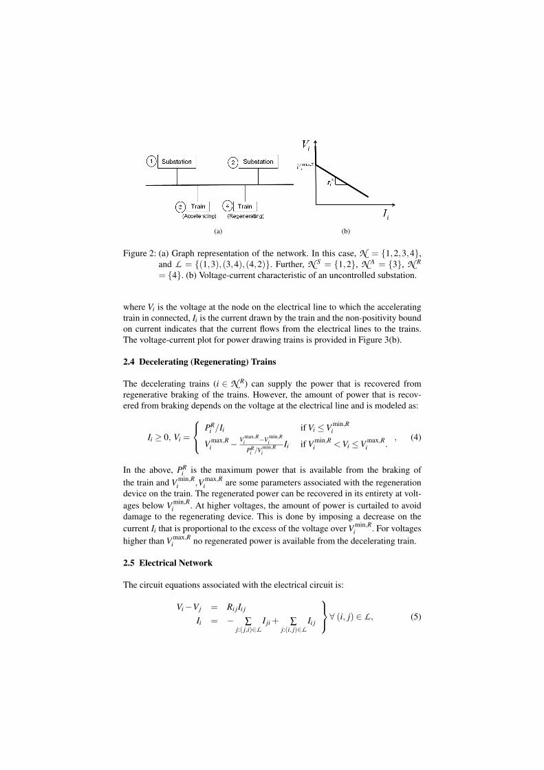
Figure 2: (a) Graph representation of the network. In this case, N = 1,2,3,4,and L = (1,3),(3,4),(4,2). Further, N S = 1,2, N A = 3, N R
= 4. (b) Voltage-current characteristic of an uncontrolled substation.
where Vi is the voltage at the node on the electrical line to which the acceleratingtrain in connected, Ii is the current drawn by the train and the non-positivity boundon current indicates that the current flows from the electrical lines to the trains.The voltage-current plot for power drawing trains is provided in Figure 3(b).
2.4 Decelerating (Regenerating) Trains
The decelerating trains (i ∈ N R) can supply the power that is recovered fromregenerative braking of the trains. However, the amount of power that is recov-ered from braking depends on the voltage at the electrical line and is modeled as:
Ii ≥ 0, Vi =
PRi /Ii if Vi ≤V min,R
i
V max,Ri − V max,R
i −V min,Ri
PRi /V min,R
iIi if V min,R
i <Vi ≤V max,Ri .
, (4)
In the above, PRi is the maximum power that is available from the braking of
the train and V min,Ri ,V max,R
i are some parameters associated with the regenerationdevice on the train. The regenerated power can be recovered in its entirety at volt-ages below V min,R
i . At higher voltages, the amount of power is curtailed to avoiddamage to the regenerating device. This is done by imposing a decrease on thecurrent Ii that is proportional to the excess of the voltage over V min,R
i . For voltageshigher than V max,R
i no regenerated power is available from the decelerating train.
2.5 Electrical Network
The circuit equations associated with the electrical circuit is:
Vi−Vj = Ri jIi j
Ii = − ∑j:( j,i)∈L
I ji + ∑j:(i, j)∈L
Ii j
∀ (i, j) ∈ L , (5)

(a) (b) (c)
Figure 3: Voltage-current characteristics of (a) substations, (b) accelerating trainsand (c) decelerating trains.
which are the Kirchoff’s Laws. In the above, Vi denotes the voltage on the electricalline at node i, Ii is the current injected into the electrical line at node i, and Ii jdenotes the current on the line (i, j) ∈ L . Note that we have used the conventionthat Ii j > 0 when current flows from i to j for (i, j) ∈ L .
3 Mathematical Program with Complementarity Constraints(MPCC)
The models for the substations eqns (1),(2) are non-differentiable. Most nonlin-ear programming algorithms assume differentiability of constraints and are inap-plicable to eqns (2),(2). Another approach to address the non-differentiability isto choose apriori for each substation the differentiable piece on which the solu-tion lies and then, solve a smooth nonlinear program. However, that will entailsolving an exponentially large number (∼ 2|N
S|) of nonlinear programs. Moreimportantly, not all of these may be feasible. To obtain a tractable formulation.we propose to address the non-differentiability by modeling using complemen-tarity constraints. This leads to other issues for optimization but these have beensuccessfully addressed in the literature as explained in Section 3.4.
3.1 Subststation without Voltage Control
We propose the following exact reformulation of the model in eqn (2) using com-plementarity constraints. In particular, the model for i ∈N SU is,
Vi =V max,Si − rS
i Ii + si,
Ii,si ≥ 0, Iisi = 0.(6)
In the above, we introduced a scalar si to model the excess of the substation volt-age over the maximum operational voltage V max,S
i when Ii = 0. In addition, si isrestricted to be nonnegative and also the product of Ii and si is required to bezero. The last constraint in eqn (6) is the so called complementarity constraint. It

requires that at any feasible solution either Ii or si vanishes. Consequently, whenIi > 0 the scalar si = 0, Vi = V max,R− rS
i Ii is imposed. On the other hand whenIi = 0, the scalar si ≥ 0 can assume a positive value thereby allowing the voltageto exceed V max,S
i . More importantly, the above constraints are all differentiable.
3.2 Voltage Controlled Substation
In an analogous manner to eqn (6), we reformulate eqn (2) using complementarityconstraints. In particular, the model for i ∈N SC is,
V min,Si ≤Vi ≤V max,S
i − rSi Ii + si,
Ii,si ≥ 0, Iisi = 0.(7)
The equivalence of eqn (2) and eqn (7) can be shown using arguments similar tothose in Section 3.1.
3.3 Relaxed Regenerating Train
The regenerating train model eqn (4) requires that voltage and current lie on twopieces - the curve ViIi =PR
i or the straight line. Clearly this model is non-differentiable.We propose to relax the constraints in eqn (4) as follows,
Vi ≤
PRi /Ii if Vi ≤V min,R
i
V max,Ri − V max,R
i −V min,Ri
PRi /V min,R
iIi if V min,R
i <Vi ≤V max,Ri
, Ii ≥ 0. (8)
This relaxation amounts to allowing the area under the graph in Figure 3(c) to befeasible as opposed to just the boundary. Since the optimization problem mini-mizes the amount of power drawn from the substations we expect to utilize all ofthe regenerated energy for powering the accelerating trains at an optimal solution.We cannot prove this statement but show in Section 4 through numerical experi-ments that the solution obtained using eqn (8) does indeed satisfy eqn (4). Also,upper limit on the voltage is not imposed when no current is drawn from the decel-erating train. This is modeled using complementarity constraints as:
ViIi ≤ PRi + si,
Vi ≤V max,R− V max,Ri −V min,R
i
PRi /V min,R
iIi + si,
Ii,si ≥ 0, Iisi = 0.
(9)
3.4 Optimization Formulation
We are interested in regulating the voltages at substations so that the power thatis drawn from the substations is minimized. Utilizing the models described in the

previous section the optimization problem can be formulated as:
min ∑i∈N S
ViIi
s.t. eqns (3), (5), (6), (7), (9).(10)
The optimization problem in eqn (10) is an instance of a Mathematical Programwith Equilibrium Constraints (MPEC) [6]. MPECs are a class of nonlinear pro-grams that include as constraints, complementarity constraints. MPECs have beenused to model problems in economics, traffic [6], structural engineering [8], chem-ical engineering [9], bioengineering [10] among others.
MPECs possess a number of numerical deficiencies [6]. Importantly, the fea-sible region for MPECs do not have a strict interior. This precludes the use ofinterior point algorithms [11, 12] which have shown to be successful in solvinglarge-scale inequality constrained nonlinear programs. These algorithms require astrictly feasible interior for the constraints. However, several studies [7, 13] havereformulated the complementarity constraints, with a strictly feasible interior, sothat interior point algorithms can be applied. In particular, we relax the comple-mentarity constraints in eqn (10) as,
Iisi ≤ ηi ∀ i ∈N S∪N R, (11)
where ηi > 0 is a chosen parameter. The above relaxation of complementarity con-straint endows the optimization problem with an interior and makes it amenableto solution using interior point algorithms. Observe that as ηi→ 0 we recover thecomplementarity conditions. Motivated by this we solve a sequence of optimiza-tion problems for ηk
i ∀ i ∈ N S ∪N R, k = 0,1,2, . . . monotonically decreasing.We refer the interested reader to Raghunathan and Biegler [7] for more details.
4 Numerical Experiments
In this section, we present numerical results on an electrical railroad covering about32 km with 23 stations. We consider 2.5 minutes of train operation.
4.1 Problem Setup
There are 8 substations along the railroad located at following distances in km:1.07, 5.55, 8.45, 12.29, 16.66, 22.01, 25.54 and 30.09. The electrical railroadhas two lines running in opposite direction. Figures 4(a) and 4(b) show respec-tively the net power demanded by trains (=∑i∈N A PA
i ) and net power regeneratedby braking trains (=∑i∈N R PR
i ). Of course, the location of the power demand andpower regeneration for different trains depends on the run-curve of the trains.Based on the assumed run-curves, the net energy demanded by the trains overthe 2.5 minute period is 979.5 kWh. The net energy available from the brakingof the trains is 497.2 kWh. The parameters for substations are set as: V max,S
i ∈

(a) (b)
Figure 4: Time profiles of (a) Net power demand, (b) Net regenerated power.
(1.58,1.68) kV, V min,Si = 1.3 kV and rS
i ∈ (0.011,0.29)Ω (Ohm). For the regener-ating trains, V max,R
i = 1.75 kV and V min,Ri = 1.7 kV. The resistivity of lines is set
to 42.7 mΩ/km.
4.2 Results
We considered two cases of substation operation:• No Voltage Control - In this scenario, |N SU |= 8,N SC = /0.• Voltage Control - In this scenario, N SU = /0, |N SC|= 8.
The computations were performed on Intel i7-3930K 3.6 GHz CPU with 16 GBRAM running Windows 7. The average CPU times for No Voltage Control was0.44 sec while for No Voltage Control was 0.66 sec. In the latter case, there were11 instances where the CPU time was > 1 sec with max CPU time of 1.78 sec.
Table 1 presents the comparison of results for the two cases. An inspection ofresults in Table 1 shows that controlling the substation voltages reduces the energyconsumed from substations by 24.69 kWh. This represents an energy savings of3% over the No Voltage Control scenario. More importantly, 97% of the regener-ated energy from braking trains is recovered in the Voltage Control case. On theother hand, in the No Voltage Control scenario only 89.2% of regenerated energyis recovered. Figure 5 plots the net power supplied from all substations at dif-ferent time instances for the two cases. The greatest difference between the twoprofiles occurs simulation time of t = 25 sec (indicated by dotted vertical line inFigure 5). Figure 6 plots profile of the voltages along the length of the railroad att = 25 sec. Observe that for Voltage Control the substations (denoted by ∗) andregenerating trains (denoted by ) operate at lower voltages. Thus, higher energyrecovery is achieved in the Voltage Control as shown in Figure 7. Further, note thatsubstations SS1, SS6, SS8 do not supply power (refer Figure 7) and in No Voltage

Table 1: Comparison of results for No Voltage Control and Voltage Control cases.
No Voltage Control Voltage Control
Energy from substations (kWh) 814.9 790.2
Energy from braking trains (kWh) 443.4 482.1
Total energy (kWh) 1258.3 1272.3
% energy recovered from braking trains 89.2 97.0
Figure 5: Optimal time profiles of power supply from substations for No VoltageControl and Voltage Control cases.
Control case the voltages at these substations exceed V max,Si (denoted by4 in Fig-
ure 6). Trains A19,A18, B11, B12, A2 recover more regenerated energy in VoltageControl case. In our numerical experiments, we have observed that eqn (4) is sat-isfied for all time instants expect for t = 49 sec. At t = 49 sec, the net demand fromaccelerating trains is only 3.55 MW while the regenerating trains produce as muchas 9.79 MW. Hence, at the optimal solution the energy recover is greatly reducedto avoid exceeding the demand and this leads to a large error. This justifies the useof the relaxation in eqn (9).
The results clearly demonstrates, as outlined in the introduction, that the highcatenary voltage reduces the recovered energy from braking trains. However, wedo notice that the total amount of energy supplied in the Voltage Control caseexceeds that of the No Voltage Control case. This can be explained through increasedline losses in the former case wherein braking trains are possibly located furtheraway from power demanding trains. In such scenarios, it may be beneficial to sup-ply energy from substations that are closer to the power demanding trains and storethe regenerated energy. We plan to explore this in a future work.

Figure 6: Optimal voltages along length of railroad at simulation time of 25 sec.
Figure 7: Power supplied by substations and regenerating trains at simulation timeof 25 sec.
5 Conclusions
We proposed a novel approach for controlling the substation voltages so as tominimize the energy consumption in railway operations. Complementarity basedmodeling was presented as a computationally efficient approach for handling con-ditional models. The numerical results clearly demonstrate the role of substationvoltage control in reducing the energy consumption by about 3% by increasingrecovered energy from braking trains over 2.5 minutes of railroad operation. Fur-

ther, the proposed solution approach enables real-time control as it is robust andcomputationally fast on standard desktop processors. The influence of storagedevices on energy consumption will be considered in a future study.
References
[1] Steimel, A., Power-electronics issues of modern electric railway systems.Advances in Electrical and Computer Engineering, 10(2), pp. 3–10, 2010.
[2] Uzuka, T., Trends in high-speed railways and the implications on power elec-tronics and power devices. 23rd International Symposium on Power Semicon-ductor Devices and IC’s, IEEE, pp. 6–9, 2011.
[3] Miyatake, M. & Ko, H., Numerical analyses of minimum energy operationof multiple trains under DC power feeding circuit. European Conference onPower Electronics and Applications.
[4] Miyatake, M. & Ko, H., Optimization of Train Speed Profile for MinimumEnergy Consumption. IEEJ Transactions on Electrical and Electronics Engi-neering, 5(3), pp. 263–269, 2010.
[5] Lu, S., Optimising Power Management Strategies for Railway Traction Sys-tems. Ph.D. thesis, 2011.
[6] Luo, Z.Q., Pang, J.S. & Ralph, D., Mathematical Programs with EquilibriumConstraints. Cambridge University Press, 1996.
[7] Raghunathan, A.U. & Biegler, L.T., An interior point method for mathemat-ical programs with complementarity constraints (MPCCs). SIAM Journal onOptimization, 15(3), pp. 720–750, 2005.
[8] Outrata, J., Kocvara, M. & Zowe, J., Nonsmooth Approach to OptimizationProblems with Equilibrium Constraints: Theory, Applications and NumericalResults. Kluwer Academic Publishers: Dordrecht, 1998.
[9] Raghunathan, A.U. & Biegler, L.T., MPEC Formulations and Algorithms inProcess Engineering. Computers and Chemical Engineering, 27, pp. 1381–1392, 2003.
[10] Raghunathan, A.U., Perez-Correa, J.R. & Biegler, L.T., Data Reconciliationand Parameter Estimation in Flux-Balance Analysis. Biotechnology and Bio-engineering, 84, pp. 700–709, 2003.
[11] Wachter, A. & Biegler, L.T., On the Implementation of an Interior-Point Fil-ter Line-Search Algorithm for Large-Scale Nonlinear Programming. Mathe-matical Programming, 106(1), pp. 25–57, 2006.
[12] Byrd, R., Hribar, M.E. & Nocedal, J., An Interior Point Method for LargeScale Nonlinear Programming. SIAM Journal on Optimization, 9(4), pp.877–900, 1999.
[13] DeMiguel, V., Friedlander, M.P., Nogales, F.J. & Scholtes, S., A two-sidedrelaxation scheme for mathematical programs with equilibrium constraints.SIAM Journal on Optimization, 16(2), pp. 587–609, 2005.