lte beyond 3.5g
DESCRIPTION
LTE beyond 3.5G. February 2010 Presentation for Departemen Elektro FTUI Ir. Dwika Sudrajat CTO and Managing Consultant [email protected] HP: 08161108571. Outline. HSPA+: Next step in 3GPP Migration Path 3GPP Long Term Evolution (LTE) LTE Peak User Performance & Mobile WiMAX Rel 1.5 - PowerPoint PPT PresentationTRANSCRIPT

LTE beyond 3.5G
February 2010Presentation for Departemen Elektro FTUI
Ir. Dwika Sudrajat CTO and Managing Consultant
[email protected]: 08161108571
1

Outline• HSPA+: Next step in 3GPP Migration Path• 3GPP Long Term Evolution (LTE)• LTE Peak User Performance & Mobile WiMAX Rel 1.5• Timeline Comparison• Migration Path Options for Today’s Mobile Operators• Summary and Conclusion
2

“Multi-carrier”: FDM and OFDM
Ch.1
Ch.2 Ch.3 Ch.4 Ch.5 Ch.6 Ch.7 Ch.8 Ch.9 Ch.10
Saving of bandwidth
Ch.3 Ch.5 Ch.7 Ch.9Ch.2 Ch.4 Ch.6 Ch.8 Ch.10
Ch.1
Conventional multicarrier techniques
Orthogonal multicarrier techniques
50% bandwidth saving
frequency
frequency

Key Technology Of LTEOFDM & OFDMA
OFDMA (Orthogonal Frequency Division Multiple Access )
Delivers higher peak data rates and increased system capacity
Services :
Video streaming
High-speed 3D and multiplayer games
Music downloads or high-speed data connectivity.
Smart Antenna
MIMO (multiple input / multiple output )
Increases subscriber data rate
AAS (adaptive antenna system )
Improves cell-edge link budget

LTE OFDM & OFDMA
• OFDM– All carriers are transmitted in parallel
– Only one user is supported at the same time
• OFDMA– Divides the carrier space into many groups
– Many users can be supported at the same time

• TDMA/FDMA operation = OFDMA• Frequency sub-channels are composed of
multiple, non-adjacent carriers
TX#4TX#3
TX#2
TX#6
TX#5
TX#1
Time
Fre
quen
cy b
in
2
4
6
8
10
12
14
16
18
20
22
24
26
28
30
0
0 1 2 3 4 5 6 7 8 9 10 11 12 13 14 15 16 17 18 19 20
Combining TDMA and FDMA

Compatible to channel dynamics in high mobility environment
Demonstrated in HW and Simulations
Demonstrate feasibility of high data rates within a limited spectrum
Optimization of OFDMA, and MIMO-OFDMA modulation schemes: Adaptive bit-loading, inter/intra band coding, utilization of side information
User #1
Total Frequency band
User #69Contention pilots
Guard Band Guard Band
OFDMA for Mobile

Crowded Spectrum: FCC Chart
http://www.ntia.doc.gov/osmhome/allochrt.pdf
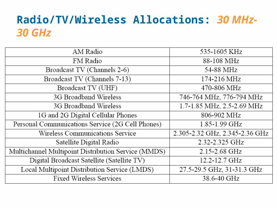
Radio/TV/Wireless Allocations: 30 MHz-30 GHz

BTS — Base Transceiver Station
BSC — Base Station Controller
Typical 2G Architecture
MSC — Mobile Switching Center
VLR — Visitor Location Register
HLR — Home Location Register
BTS
BSCMSC/VLR
HLRBSC
GMSC
CO
BSC
BSCMSC/VLR
CO
PSTN
PLMN
CO
Tandem Tandem
SMS-SC
PSDN

PSTN-to-Mobile Call
(STP)
(SCP)
PSTNPLMN
(SSP)(SSP)BSSMS
PLMN(Home)(Visitor)
(STP)
HLR
GMSC
(SSP)
VMSC
VLR
IAM
6
2
Where is the subscriber?
5Routing Info
3Provide Roaming
4
SCP
1
IAM
514 581 ...
ISUP
MAP/ IS41 (over TCAP)
Signalingover SS7

SS7BTS
BSCMSC
VLR
HLRAuC
GMSC
BSS
PSTN
NSS
AE
CD
PSTNAbis
B
H
MS
BSS — Base Station System
BTS — Base Transceiver Station
BSC — Base Station Controller
NSS — Network Sub-System
MSC — Mobile-service Switching Controller
VLR — Visitor Location Register
HLR — Home Location Register
AuC — Authentication Server
GMSC — Gateway MSC
2.5G Architectural Detail
SGSN — Serving GPRS Support Node
GGSN — Gateway GPRS Support Node
GPRS — General Packet Radio Service
IP
2G+ MS (voice & data)
PSDNGi
SGSN
Gr
Gb
Gs
GGSN
Gc
Gn
2G MS (voice only)

3G rel99 Architecture (UMTS) — 3G Radios
SS7
IP
BTS
BSCMSC
VLR
HLRAuC
GMSC
BSS
SGSN GGSN
PSTN
PSDN
CN
CD
GcGr
Gn Gi
Abis
Gs
B
H
BSS — Base Station System
BTS — Base Transceiver Station
BSC — Base Station Controller
RNS — Radio Network System
RNC — Radio Network Controller
CN — Core Network
MSC — Mobile-service Switching Controller
VLR — Visitor Location Register
HLR — Home Location Register
AuC — Authentication Server
GMSC — Gateway MSC
SGSN — Serving GPRS Support Node
GGSN — Gateway GPRS Support Node
AE PSTN
2G MS (voice only)
2G+ MS (voice & data)
UMTS — Universal Mobile Telecommunication System
Gb
3G UE (voice & data)
Node B
RNC
RNS
Iub
IuCS
ATM
IuPS

3G rel4 Architecture (UMTS) — Soft Switching
SS7
IP/ATM
BTS
BSCMSC Server
VLR
HLRAuC
GMSC server
BSS
SGSN GGSN
PSTN
PSDN
CN
CD
GcGr
Gn Gi
Gb
Abis
Gs
B
H
BSS — Base Station System
BTS — Base Transceiver Station
BSC — Base Station Controller
RNS — Radio Network System
RNC — Radio Network Controller
CN — Core Network
MSC — Mobile-service Switching Controller
VLR — Visitor Location Register
HLR — Home Location Register
AuC — Authentication Server
GMSC — Gateway MSC
SGSN — Serving GPRS Support Node
GGSN — Gateway GPRS Support Node
ANc
2G MS (voice only)
2G+ MS (voice & data)
Node B
RNC
RNS
Iub
IuCS
IuPS
3G UE (voice & data)
Mc
CS-MGW
CS-MGWNb
PSTNMc
ATM

3G rel5 Architecture (UMTS) — IP Multimedia
Gb/IuPS
A/IuCS
SS7
IP/ATM
BTS
BSCMSC Server
VLR
HSSAuC
GMSC server
BSS
SGSN GGSN
PSTN
CN
CD
GcGr
Gn Gi
Abis
Gs
B
H
IM — IP Multimedia sub-system
MRF — Media Resource Function
CSCF — Call State Control Function
MGCF — Media Gateway Control Function (Mc=H248,Mg=SIP)
IM-MGW — IP Multimedia-MGW
Nc
2G MS (voice only)
2G+ MS (voice & data)
Node B
RNC
RNS
Iub
3G UE (voice & data)
Mc
CS-MGW
CS-MGWNb
PSTNMc
IuCS
IuPS
ATM
IM
IPPSTN
Mc
MGCF
IM-MGW
MRF
CSCF
Mg
Gs
IP Network

3GPP LTE and SAE• SAE architecture
MME – Mobility Management Entity UPE – User Plane EntityAS – Access SystemRed indicates new functional element / interface

3GPP LTE and SAE
• Status of the work for LTE–Downlink Parameter for OFDM
Transmission BW1.25 MHz 2.5 MHz 5 MHz 10 MHz 15 MHz 20 MHz
Sub-frame duration 0.5 ms
Sub-carrier spacing 15 kHz
Sampling frequency 1.92 MHz(1/2 3.84 MHz)
3.84 MHz 7.68 MHz(2 3.84 MHz)
15.36 MHz(4 3.84 MHz)
23.04 MHz(6 3.84 MHz)
30.72 MHz(8 3.84 MHz)
FFT size 128 256 512 1024 1536 2048
Number of occupied
sub-carriers†, ††
76 151 301 601 901 1201
Number of OFDM symbols per sub frame
(Short/Long CP)
7/6
CP length
(μs/samples)
Short (4.69/9) 6,(5.21/10) 1*
(4.69/18) 6,(5.21/20) 1
(4.69/36) 6,(5.21/40) 1
(4.69/72) 6,(5.21/80) 1
(4.69/108) 6,
(5.21/120) 1
(4.69/144) 6,(5.21/160) 1
Long (16.67/32) (16.67/64) (16.67/128) (16.67/256) (16.67/384) (16.67/512)
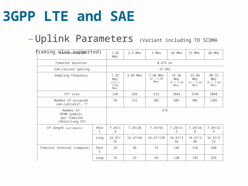
3GPP LTE and SAE
–Uplink Parameters (Variant including TD SCDMA framing also
supported) Transmission BW 1.25 MHz
2.5 MHz 5 MHz 10 MHz 15 MHz 20 MHz
Timeslot duration 0.675 ms
Sub-carrier spacing 15 kHz
Sampling frequency 1.92 MHz
(1/2 3.84 MHz)
3.84 MHz 7.68 MHz(2 3.84 MHz)
15.36 MHz
(4 3.84 MHz)
23.04 MHz
(6 3.84 MHz)
30.72 MHz
(8 3.84 MHz)
FFT size 128 256 512 1024 1536 2048
Number of occupied sub-carriers†, ††
76 151 301 601 901 1201
Number of OFDM symbols
per Timeslot(Short/Long CP)
9/8
CP length (μs/samples) Short 7.29/14 7.29/28 7.29/56 7.29/112 7.29/168 7.29/224
Long 16.67/32 16.67/64 16.67/128 16.67/256
16.67/384
16.67/512
Timeslot Interval (samples) Short 18 36 72 144 216 288
Long 16 32 64 128 192 256

SC-FDMA (1)
• Low PAPR
• Cyclic prefix guard interval: enable cost-effective frequency domain block processing at receiver side
• Two types of SC transmission– Localized transmission: multi-
user scheduling gain in frequency domain
– Distributed transmission: robust transmission for control channels and high mobility UE
ConstellationMapping
M-pointDFT
Spreading
Add Cyclic Prefix
InputBit Stream Serial to
Parallel
Symbol to subcarrier mapping
N-pointIFFT
Parallel to serial
0S1S
1MS
0s1s
1Ms
0x1x
1Nx
0X1X
1NX
M-pointDFT
Spreading
Symbol to subcarrier mapping
N-pointIFFT
0
0
0
M-pointDFT
Spreading
Symbol to subcarrier mapping
N-pointIFFT
0
0
0
0
Localized: contiguous subcarriers
Distributed: evenly spaced subcarriers

SC-FDMA (2)
• Localized transmission– Need to feedback channel state information
– Mainly for low-to-medium mobility users
• Distributed transmission– Mainly for high mobility users
• Orthogonal resource subspace division– Transmission bandwidth is divided into localized band and distributed band
– Each band is further divided into several subbands for inter-cell interference avoidance/concentration
– A subband out of each band in a cell is operated in whispering mode; UEs using a channel belonging to the same subband in neighboring cells can be operated in speaking mode
L-subband 3L-subband 3 L-subband 3
frequency
* Different colors denote different UEs’ channel D-subband 1 D-subband 3
D-subband 2
Localized band Distributed band
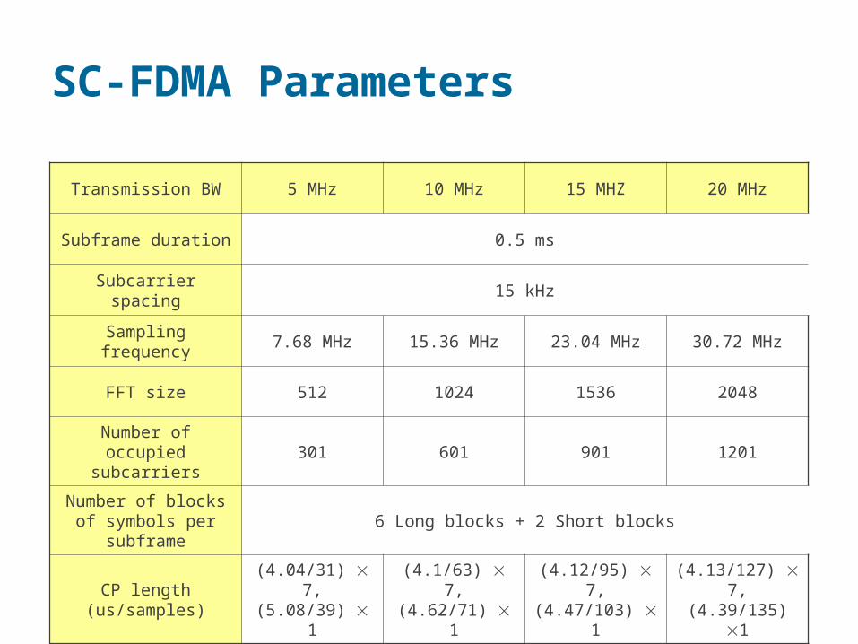
SC-FDMA Parameters
Transmission BW 5 MHz 10 MHz 15 MHZ 20 MHz
Subframe duration 0.5 ms
Subcarrier spacing 15 kHz
Sampling frequency 7.68 MHz 15.36 MHz 23.04 MHz 30.72 MHz
FFT size 512 1024 1536 2048
Number of occupied subcarriers
301 601 901 1201
Number of blocks of symbols per subframe
6 Long blocks + 2 Short blocks
CP length (us/samples)(4.04/31) 7,(5.08/39) 1
(4.1/63) 7,(4.62/71) 1
(4.12/95) 7,(4.47/103) 1
(4.13/127) 7,(4.39/135) 1
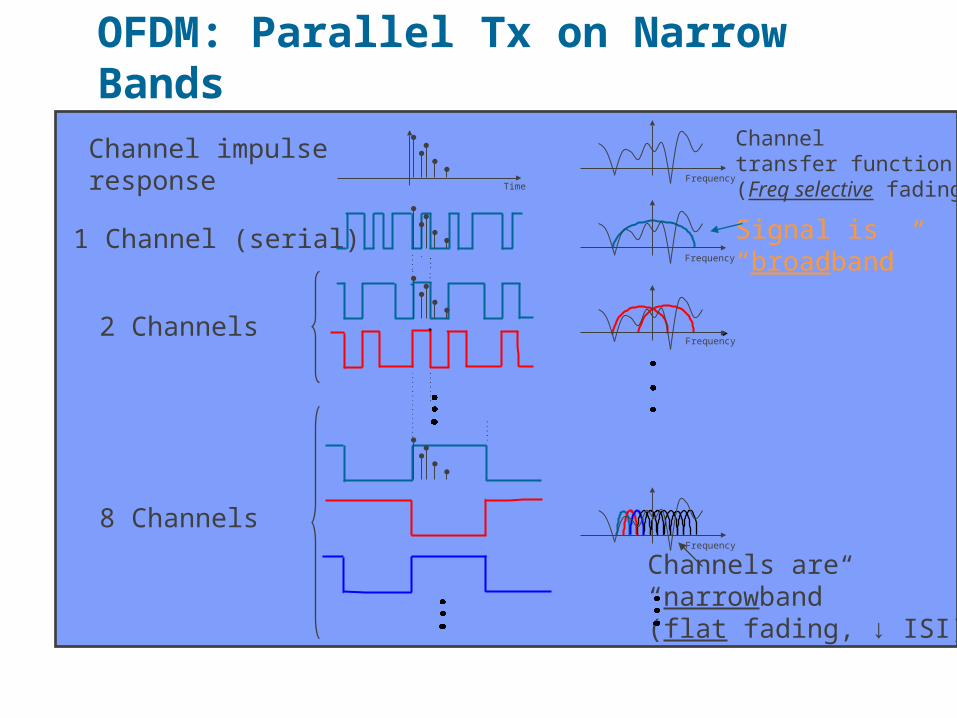
OFDM: Parallel Tx on Narrow Bands
Channel impulse response
1 Channel (serial)
Channeltransfer function(Freq selective fading)
Channels are “narrowband”(flat fading, ↓ ISI)
2 ChannelsFrequency
Frequency
8 ChannelsFrequency
FrequencyTime
Signal is “broadband”

MIMO: Spatial Diversity, Spatial Multiplexing w/ Multiple Antennas
Example: Simple Selection Diversity (Rx only), Diversity Gains..

SISO, MISO, SIMO, MIMO, SDMA…
SISO– Single Input, Single Output
MISO
– Multiple Input, Single Output
SIMO
– Single Input, Multiple Output
MIMO
– Multiple Input, Multiple Output
SDMA

Adaptive Antenna Gains (Tx or Rx)Diversity
• differently fading paths• fading margin reduction• no gain when noise-limited
Coherent Gain• energy focusing• improved link budget• reduced radiation
Interference Mitigation• energy reduction• enhanced capacity• improved link budget
Enhanced Rate/Throughput• co-channel streams• increased capacity• increased data rate

TDMA Overview
C B A C B A C B A C B A
C
A
B
Time
f0
Freq
uenc
y

Channel PartitioningMAC protocols. Issues
TDMA: time division multiple access • Access to channel in "rounds"
• Each station gets fixed length slot (length = pkt trans time) in each round
• Unused slots go idle
• Example: 6-station LAN, 1,3,4 have pkt, slots 2,5,6 idle
• Does not leverage statistical multiplexing gains here

A A
B B
C C
Freq
uenc
y
Time
f2
f1
f0
FDMA Overview
Need substantial guard bands: inefficient

CDMA
Sender Receiver
Code A
A
Code B
B
AB
AB
CBC
A
Code A
AB
C
Time
Freq
uenc
y
BC
B
A
Base-band Spectrum Radio Spectrum
spread spectrum

Summary of Multiple Access
FDMA
TDMA
CDMA
time
time
time
pow
er
pow
er
pow
er
frequency
frequency
frequency

OFDMA: a mix of FDMA/TDMA: (OFDM modulation) Sub Channels are allocated in the Frequency Domain, OFDM Symbols allocated in the Time Domain. Dynamic scheduling leverages statistical multiplexing gains, and allows adaptive
modulation/coding/power control, user diversity
TDMA
TDMA\OFDMA
t
N
m
OFDMA

3GPP Long Term Evolution (LTE)
• 3GPP (LTE) is Adopting: – OFDMA in DL with 64QAM– All IP e2e Network– Channel BWs up to 20 MHz– Both TDD and FDD profiles– Flexible Access Network– Advanced Antenna Technologies– UL: Single-Carrier FDMA (SC-FDMA), (64QAM optional)
• LTE is adopting technology & features already available with Mobile WiMAX– Can expect similar long-term performance benefits and
trade-offs
33

LTE: Not a Simple 3G Upgrade
• LTE Represents a Major Upgrade from CDMA-Based HSPA (or EV-DO)–No longer a “simple” SW upgrade:
• CDMA to OFDMA, represent different technologies
• Circuit switched to IP e2e network
–Also requires new spectrum to take full advantage of wider channel BWs and …
–Requires dual-mode user devices for seamless internetwork connectivity
34

LTE Projections & Mobile WiMAXFDD 2 x 20 MHz Channel BW
Parameter
Reported LTE Results
WiMAX Rel 1.5Motorola1 T-Mobile2 Qual-
comm3
BS Antenna 2x2 4x4 2x4 4x2 2x2 4x4
Channel BW 2 x 20 MHz 2 x 20 MHz
Mod-Code Rate 64QAM-5/6 64QAM-5/6
64QAM-? 64QAM-5/6
DL Peak User Rate
117 Mbps
226 Mbps
144 Mbps
277 Mbps
144.6 Mbps
289 Mbps
MS Antenna 1x2 1x2 1x2
Mod-Code Rate 64QAM4-? 16QAM4-? 64QAM-5/6
UL Peak User Rate
? ? 50.4Mbps
75 Mbps
69.1 Mbps
35
1. Motorola website, “LTE In Depth” , Reference does not show UL peak rate projections2. “Trials–Ensuring Success for Innovation”, Joachim Horn, T-Mobile, NGMN Conference presentation, June 25-27,20083. “3GPP Long-Term Evolution (LTE)”, Qualcomm, January 20084. 64QAM is optional for UL in LTE specification, 16QAM is mandatory
1. Motorola website, “LTE In Depth” , Reference does not show UL peak rate projections2. “Trials–Ensuring Success for Innovation”, Joachim Horn, T-Mobile, NGMN Conference presentation, June 25-27,20083. “3GPP Long-Term Evolution (LTE)”, Qualcomm, January 20084. 64QAM is optional for UL in LTE specification, 16QAM is mandatory

Other Key Parameter ComparisonsParameter LTE Mobile WiMAX Rel 1.5
Duplex FDD and TDD FDD and TDD
Frequency Band for Performance Analysis
2000 MHz 2500 MHz
Channel BW Up to 20 MHz Up to 20 MHz
Downlink OFDMA OFDMA
Uplink SC-FDMA OFDMA
DL Spectral Efficiency1 1.57 bps/Hz/Sector (2x2) MIMO2
1.59 bps/Hz/Sector (2x2) MIMO
UL Spectral Efficiency1 0.64 bps/Hz/Sector (1x2) SIMO2
0.99 bps/Hz/Sector (1x2) SIMO
Mobility Support Target: Up to 350 km/hr Up to 120 km/hr
Frame Size 1 millisec 5 millisec
HARQ Incremental Redundancy Chase Combining
Link Budget Typically limited by Mobile Device Typically limited by Mobile Device
Advanced Antenna Support
DL: 2x2, 2x4, 4x2, 4x4UL: 1x2, 1x4, 2x2, 2x4
DL: 2x2, 2x4, 4x2, 4x4UL: 1x2, 1x4, 2x2, 2x4
36
1. Spectral efficiency is based on NGMN Alliance recommended evaluation methodology
2. Reference for LTE Spectral Efficiency: Motorola website, “LTE in Depth”. 1. Spectral efficiency is based on NGMN Alliance recommended evaluation methodology
2. Reference for LTE Spectral Efficiency: Motorola website, “LTE in Depth”.

What is MIMO? Multiple Input Multiple Output
4x1 STTDCode Rate = 1
4x2 STTDCode Rate = 2
4x4 Spatial MultiplexingCode Rate = 4
UL virtual MIMO
UL Adaptive MIMO
Down link
Up link
MIMO Increases throughput

MIMO Channels
(Rich-Scattering Channels)

3GPP Timeline
39
Mobile WiMAX time to market
advantage
IMT-Advanced
2008 2009 2010 2011 2012
CDMA-Based OFDMA-Based
LTE & LTE Advanced
IP e2e Network
3GPP
HSPA+Rel-7 & Rel-8
Ckt Switched Network
HSPARel-6

Upgrade Path for Existing Operators
40
Radio Access Network Core Network
2G, 3G, GSM, EVDO, HSPA
Backhaul Network
2G, 3G, Core Network
All-IP Core Network
Next Generation Access Network
Data Overlay or Replacement
LTE
Comparable CAPEX
LTE in 2+ years.Both require new spectrum
Conversion to all-IP core & increased backhaul capacity required in either case
Increased BH Capacity
T1,E1s
Support for Legacy RAN

Comparing the End-to-End Network
41
Source: LTE/SAE: 3GPP, Mobile WiMAX: WiMAX Forum Network Specification Release 1.0
LTE/SAE User Plane & Data FlowLTE/SAE User Plane & Data Flow
L1
L1
L1
-
L2
Relay
L1
-
Serving GWE-UTRAN
UE/MS LTE-Uu
PDN GW
L1
-
L2
L1
-
L2
Relay
S1-U S5 SGi
UDP/IP UDP/IP
PDCP GTP U
UDP/IP
GTP UGTP U GTP U
RLC RLC UDP/IP
e.g. IP,PPP
e.g. IP,PPP
L2
Application
PDCP
MAC MAC
Multiple layers, Many nodes and proprietary protocols

42
Thank You for Your Attention

Appendix
43

WLAN (802.11n/이후 ) WiBro I/II 3G LTE 4G
(new capabilities)
Spectrum
5~6GHz ( 및 2.4~2.5GHz)
Unlicensed band
2.3~2.4GHz,
?
Licensed band
2.5~2.6GHz,
2G/3G 대역Licensed band
3.4GHz ~ 6GHz
Licensed & Unlicensed band
Bandwidth
(MHz)
20, 40/
20, 40, 80, (100)
I : 10
II : 10, 20, 401.25, 2.5, 5, 10, 15,
205, 10, 20, 40, 80, (100)
Duplexing TDD TDD FDD & TDD FDD & TDD, Hybrid
Modulation & Multiple
Access
OFDM/TDMA
(CSMA/CA 기반 )
OFDMA
DL: OFDMA,
OFDM-CDMA
UL: SC-FDMA, OFDMA
DL: OFDMA, MC-CDMA, …
UL: SC-FDMA, OFDMA,
GMC-FDMA, …
Peak Data Rate
216Mbps/
1Gbps
I : ~ 50Mbps
II : ~ 210Mbps
DL: 100Mbps/20MHz
UL: 50Mbps/20MHz100Mbps ~ 1Gbps
Mobility Nomadic I : 60km/h
II : ?350km/h > 350km/h
Cell coverage
Pico, hot spot Micro/pico Macro/microMacro/micro/pico/hot
spot/relay link
( 다중 동작 모드 )
Comparison of WLNA, WiBro, 3G LTE, and 4G

MSC
HLR
SMS-SC
A Ref (A1, A2, A5)
STM over T1/T3
A Ref (A1, A2, A5)
STM over T1/T3
PSTNSTM over T1/T3 or
AAL1 over SONET
BSC
BSC
Proprietary Interface
BTS
BTS
Proprietary Interface
BTS
IS-95
MS
IS-95
MS
BTS — Base Transceiver StationBSC — Base Station ControllerMS — Mobile StationMSC — Mobile Switching CenterHLR — Home Location RegistrySMS-SC — Short MessageService — Serving Center
STM — Synchronous Transfer Mode
Ater Ref (A3, A7)
A1 — Signaling interface for call control and mobility
Management between MSC and BSC
A2 — 64 kbps bearer interface for PCM voice
A5 — Full duplex bearer interface byte stream (SMS ?)
A3 — Signaling interface for inter-BSC mobile handoff
A7 — Bearer interface for inter-BSC mobile handoff
2G cdmaOne (IS-95 + IS-41)

CDMA2000 1x Network
BTS — Base Transceiver StationBSC — Base Station ControllerMS — Mobile StationMSC — Mobile Switching CenterHLR — Home Location RegistrySMS-SC — Short MessageService — Serving Center
STM — Synchronous Transfer ModePDSN — Packet Data Serving Node
AAA — Authentication, Authorization, and AccountingHome Agent — Mobile IP Home Agent
A10 — Bearer interface between BSC (PCF) and PDSN for packet dataA11 — Signaling interface between BSC (PCF) and PDSN for packet data
MSC
PSTN
A Ref (A1, A2, A5) STM over T1/T3
STM over T1/T3 or
AAL1 over SONET
HLR
SMS-SC
BSCProprietary Interface
BTS
BTS
IS-2000
MS
PDSN
HomeAgent
IPFirewall
IPRouter
Internet
PrivataData
Network
IPRouter
AQuarter Ref (A10, A11)
IP over Ethernet/AAL5
AAA
RADIUS over UDP/IP

1xEVDO — IP Data Only
IS-2000
IPBTS
IS-2000
IPBTS
IP BSC IPRouter
PDSN HomeAgent
IPFirewall
IPRouter
Internet
PrivataData
Network
IP BTS - IP Base Transceiver StationIP BSC - IP Base Station ControllerAAA - Authentication, Authorization, and AccountingPDSN - Packet Data Serving NodeHome Agent - Mobile IP Home Agent
AAA
RADIUS over UDP/IP

Nextgen MSC ?
1XEVDV — IP Data and Voice
Packet switched voice
P ST N
SIPProxy
SIP
SIP
SGW
SS7
MGCF(Softswitch)
SCTP/IP
H.248 (Maybe MGCP)
MGW
Circuit switched voice
PDSN +Router
AAA HomeAgent
Internet
IPFirewall
IPRouter
PrivataData
Network
IS-2000
IPBTS
SIP Proxy — Session Initiation Protocol Proxy Server
MGCF — Media Gateway Control Function
SGW — Signaling Gateway (SS7)
MGW — Media Gateway (Voice)
IS-2000
IPBTS
IP BSC