beyond conformance testing in 3gpp lte white...
TRANSCRIPT

Beyond Conformance Testing in 3GPP LTE
White Paper

Beyond Conformance Testing in 3GPP LTE
White Paper
Published 22nd June 2009
Writers: Tommi Jämsä (EB), Juha Ylitalo (EB), Janne Kolu (EB),
Petteri Heino (EB), Jonne Piisilä (EB), Sanna Mäkeläinen (EB),
Jussi Laakso (Upknowledge)
Copyright 2009 EB (Elektrobit). All rights reserved.
The information contained herein is subject to change without
notice. EB retains ownership of and all other rights to the material
expressed in this document. Any reproduction of the content of this
document without prior written permission from EB is prohibited.

BEYOND CONFORMANCE TESTING IN 3GPP LTE 3
TABLE OF CONTENTS
1. ABSTRACT.........................................................................................................................................................................4
2. inTRoduCTion................................................................................................................................................................5
2.1 MobiledataBusinessdrivers............................................................................................................................5
2.2 LTE–nextGenerationofMobiledata.............................................................................................................5
2.3 LTERadioFundamentals...................................................................................................................................6
2.4 LTE-Advanced......................................................................................................................................................8
3. PRoduCTTESTinGinLTE...............................................................................................................................................9
3.1 FieldTesting........................................................................................................................................................9
3.2 RadioChannelEmulation...................................................................................................................................9
3.3 ConformanceTesting.........................................................................................................................................9
3.4 BeyondConformanceTesting...........................................................................................................................10
4. RAdioChAnnELModELS..............................................................................................................................................12
4.1 RadioChannelModelsforLTEConformanceTesting.....................................................................................12
4.2 RadioChannelModelsforBeyondConformanceTesting..............................................................................12
4.2.1 SCMModel..............................................................................................................................................13
4.2.2 SCMEModel...........................................................................................................................................14
4.2.3 LTEEvaluationModel............................................................................................................................14
4.2.4 WinnERModels.....................................................................................................................................15
4.2.5 iMT-AdvancedChannelModels............................................................................................................15
4.2.6 ComparisonofGSCMModels...............................................................................................................16
5. SuMMARy.........................................................................................................................................................................17
6. EBSoLuTionS..................................................................................................................................................................17
7. REFEREnCES.....................................................................................................................................................................18

BEYOND CONFORMANCE TESTING IN 3GPP LTE4
ABSTRACT1.
The3rdGenerationPartnershipProject(3GPP)LongTerm
Evolution(LTE)standardwasformallyfrozeninMarch2009.
ThefreezingofthestandardspeedsupLTEproductdevelop-
mentandtesting.ThisWhitePaperintroducesthe3GPP
LTEtechnologyanddiscussestheconformanceandbeyond
conformancetestaspects.ThepaperdescribeshowLTE
products,systemsandapplicationsaretestedinarealistic
wirelessenvironment–notinthefieldbutinalaboratory.
3GPP 3rdGenerationPartnershipProject
AoA AngleofArrival
Aod Angleofdeparture
AWGn AdditiveWhiteGaussiannoise
B3G Beyond3G
BER BitErrorRate
BLER BLockErrorRate
BSC BaseStationController
CdL ClustereddelayLine
enodeB evolvednodeB(LTEbasestation)
EPA ExtendedPedestrianAchannelmodel
ETu ExtendedTypicalurbanchannelmodel
EVA ExtendedVehicularAchannelmodel
hSdPA highSpeeddownlinkPacketAccess
hSPA highSpeedPacketAccess
hSPA+ hSPAevolution
Flash-oFdM FastLow-latencyAccesswithSeamlesshandoff–oFdM
GSCM Geometry-basedStochasticChannelModel
iMT-2000 internationalMobileTelecommunications(global3Gstandard)
iMT-Advanced iMT-Advanced(global4Gstandard)
iPTV internetProtocolTelevision
iTu internationalTelecommunicationunion
iTu-R iTuRadiocommunicationsector
LoS LineofSight
LSP LargeScaleParameter
LTE LongTermEvolution(3.9G)
LTE-Advanced LongTermEvolutionAdvanced(4G)
MiMo Multiple-inputMultiple-output(anymulti-antennasystem)
nLoS nonLineofSight
oFdM orthogonalFrequencydivisionMultiplexing
oFdMA orthogonalFrequencydivisionMultipleAccess
PAPR PeaktoAveragePowerRatio
QoS QualityofService
RnC RadionetworkController
RRM RadioResourceManagement
SAE SystemArchitectureEvolution
SC-FdMA SingleCarrierFrequencydivisionMultipleAccess
SCM SpatialChannelModel
SCME SCMExtended
TdL TappeddelayLine
uE userEquipment
uMTS universalMobileTelecommunicationsSystem
WCdMA WidebandCodedivisionMultipleAccess
WinnER WirelessworldinitiativenEwRadio(projectname)
ABBREviATiONS
Thebenefitsofbeyondconformancetestingcomparedto
standardconformancetestingareexplained.LTEterminal
andbasestationmanufacturersaswellasoperatorsare
recommendedtogobeyondbasictestingandcarryout
performancemeasurementsalreadyintheearlyphasesof
LTEproductdevelopment.TheWhitePaperalsodiscusses
thedifferenttestingmethodsandintroduceskeyradio
channelmodelswhichcanbeusedinthetestingprocess.
BEYOND CONFORMANCE TESTING IN 3GPP LTE 5
iNTROdUCTiON2.
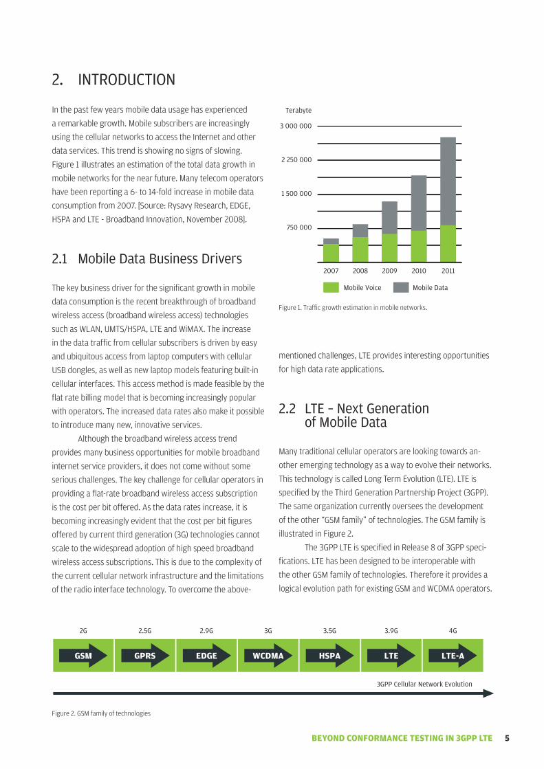
inthepastfewyearsmobiledatausagehasexperienced
aremarkablegrowth.Mobilesubscribersareincreasingly
usingthecellularnetworkstoaccesstheinternetandother
dataservices.Thistrendisshowingnosignsofslowing.
Figure1illustratesanestimationofthetotaldatagrowthin
mobilenetworksforthenearfuture.Manytelecomoperators
havebeenreportinga6-to14-foldincreaseinmobiledata
consumptionfrom2007.[Source:RysavyResearch,EdGE,
hSPAandLTE-Broadbandinnovation,november2008].
Mobile data Business drivers2.1
Thekeybusinessdriverforthesignificantgrowthinmobile
dataconsumptionistherecentbreakthroughofbroadband
wirelessaccess(broadbandwirelessaccess)technologies
suchasWLAn,uMTS/hSPA,LTEandWiMAX.Theincrease
inthedatatrafficfromcellularsubscribersisdrivenbyeasy
andubiquitousaccessfromlaptopcomputerswithcellular
uSBdongles,aswellasnewlaptopmodelsfeaturingbuilt-in
cellularinterfaces.Thisaccessmethodismadefeasiblebythe
flatratebillingmodelthatisbecomingincreasinglypopular
withoperators.Theincreaseddataratesalsomakeitpossible
tointroducemanynew,innovativeservices.
Althoughthebroadbandwirelessaccesstrend
providesmanybusinessopportunitiesformobilebroadband
internetserviceproviders,itdoesnotcomewithoutsome
seriouschallenges.Thekeychallengeforcellularoperatorsin
providingaflat-ratebroadbandwirelessaccesssubscription
isthecostperbitoffered.Asthedataratesincrease,itis
becomingincreasinglyevidentthatthecostperbitfigures
offeredbycurrentthirdgeneration(3G)technologiescannot
scaletothewidespreadadoptionofhighspeedbroadband
wirelessaccesssubscriptions.Thisisduetothecomplexityof
thecurrentcellularnetworkinfrastructureandthelimitations
oftheradiointerfacetechnology.Toovercometheabove-
mentionedchallenges,LTEprovidesinterestingopportunities
forhighdatarateapplications.
LTE – Next Generation 2.2 of Mobile data
Manytraditionalcellularoperatorsarelookingtowardsan-
otheremergingtechnologyasawaytoevolvetheirnetworks.
ThistechnologyiscalledLongTermEvolution(LTE).LTEis
specifiedbytheThirdGenerationPartnershipProject(3GPP).
Thesameorganizationcurrentlyoverseesthedevelopment
oftheother“GSMfamily”oftechnologies.TheGSMfamilyis
illustratedinFigure2.
The3GPPLTEisspecifiedinRelease8of3GPPspeci-
fications.LTEhasbeendesignedtobeinteroperablewith
theotherGSMfamilyoftechnologies.Thereforeitprovidesa
logicalevolutionpathforexistingGSMandWCdMAoperators.
Figure1.Trafficgrowthestimationinmobilenetworks.
Figure2.GSMfamilyoftechnologies
2007 2008 2009 2010 2011
Mobile voice Mobile data
Terabyte
3 000 000
2 250 000
1 500 000
750 000
2G 2.5G 2.9G 3G 3.5G 3.9G 4G
3GPP Cellular Network Evolution
GSM GPRS EDGE WCDMA HSPA LTE LTE-A

BEYOND CONFORMANCE TESTING IN 3GPP LTE6
LTEcoversanewradiointerfaceandenhancedcore
networkarchitecture(SAE)thatisbasedcompletelyoniP
transport.LTEisexpectedtosubstantiallyimprovecellcapac-
ity,end-userthroughput,provideenhancedQualityofService
(QoS)andreducethelatencyexperiencedbytheuser.These
featuresareexpectedtofinallymakemobilebroadband
arealityandbringwithitasignificantlyimproveduser
experience.ThesefeaturesallowLTEtosupportnew,more
demandingservices,suchasiPTV,musicandvideosharing,
interactivegamingandothermultimediaapplications.Some
keyfeaturesofLTEarelistedbelow.
downlinkpeakdataratesofmorethan100Mbps•
anduplinkpeakdataratesintherangeof50Mbps.
RadiointerfacebasedonoFdMAandSC-FdMA•
withsupportforhighordermodulation(64-QAM).
Supportforflexiblecarrierbandwidthsranging•
from1.25Mhzupto20Mhz.
Supportforawidevarietyofnewandexisting•
spectrumbands.
SupportforFddandTdddeployments.•
Supportforseamlesshandoverstoexisting•
3GPPcellularnetworks.
Supportformulti-antennaMiMoconfigurations•
bothintheterminalandinthebasestation.
LTEcoveragewillmostlikelybeprovidedforurbancenters
first,whereitwillcomplementtheexisting2Gand3Gnetwork
coverage.
LTE Radio Fundamentals2.3
TheLTEradiointerfacecarriesdataandcontrolsignals
betweentheLTEterminalandthebasestation,morespecifi-
callyknownastheevolvednodeB(enodeB).inGSM/WCdMA
systemsthebasestationisonlyresponsibleforthephysical
layerprocessing,andtheBSC/RnChandlescriticalRadio
ResourceManagement(RRM)relatedtasks.inLTEthebase
stationissolelyresponsibleforallradio-relatedprocessing.
TheLTEdownlinkradiotransmissionisbasedon
orthogonalFrequencydivisionMultiplexing(oFdM).oFdMis
aso-calledmulticarriermodulationtechnique,inwhichthe
channelbandwidthisdividedintoanumberofsubcarriers
(Figure3).Eachsubcarrierisindividuallymodulatedwith
apartoftheoverallbitstreamtobetransmitted.oFdM
providesseveralbenefitsthatmakeitasuitablechoice
forwirelesstransmission.oFdM-basedreceiversareless
complexthanWCdMAreceivers,whichdirectlyrelatesto
thedevelopmentcostsofuEandmakingoFdMwellsuitable
fordownlink.oFdMprovidesgoodprotectionagainst
inter-Symbolinterference(iSi),aswellasagainstnarrowband
interferenceingeneral.inaddition,implementationofthe
flexiblechannelbandwidthisrelativelyeasywithoFdM-based
systems.Thebandwidthcanbescaledbysimplychangingthe
numberofsubcarriersusedfortransmission.oFdMisalso
usedinWLAnandWiMAX.
WhatseparatesoFdMfromnormalfrequencydivision
multiplexingisthesubcarrierspacing.Bycarefullyselecting
thecorrectparametersthesubcarriersaremadeorthogonal
ornon-interferingtoeachother.Thisallowsthesubcarriersto
beplacedclosertoeachotherinthefrequencydomain,thus
increasingthespectralefficiencyofthetransmission.
LTEradiousesoFdMsomewhatdifferentlyinthe
downlinkandintheuplink.inthedownlinkthebasicoFdM
functionalityisextendedtoalsoprovidethemeansfor
multipleaccess.ThisvariationofoFdMiscalledorthogonal
FrequencydivisionMultipleAccess(oFdMA).WithoFdMAthe
LTEbasestationtransmitstodifferentusersbyusingdifferent
setsofsubcarriers,asillustratedinFigure4.
Thesubcarrierallocationcanbechangedrapidlyin
ordertoadapttochangingradiochannelconditions.TheLTE
basestationmakestheradioresourceallocationdecision
byemployingRRMalgorithms.Theuplinkanddownlink
resourcesareallocatedindependentlyofeachother.Theallo-
cationcriterionisnotspecifiedinthe3GPPspecifications,but
itcouldbebasedonthechannelqualityfeedbackreportedby
themobileterminals,forexample.
oneofthedrawbacksofoFdMAistherelativelyhigh
PeaktoAveragePowerRatio(PAPR).TheoFdMAsymbolscan
Figure3.illustrationofoFdMtechnology.Thechannelbandwidthisdividedtocloselyspacedorthogonalsub-carriers.
OFdM SubcarriersChannel BW
ff

BEYOND CONFORMANCE TESTING IN 3GPP LTE 7
havehighamplitudepeaks,whichrequiresadvancedlinear
poweramplifiersandinpracticeleadstopowerinefficiency.
oFdMmodulationwasdeemedunfeasibleforLTEterminal
transmission.Therefore,amorepower-efficienttransmission
scheme,knownasSingleCarrierFrequencydivisionMultiple
Access(SC-FdMA),wasdevelopedfortheuplinktransmission.
SC-FdMAisinprinciplequitesimilartooFdMA.Themain
differenceisthatwithSC-FdMAdataistransmittedeffectively
onasymbol-by-symbolbasis.ThisapproachproducesaPAPR
levelwhichissignificantlysmallerthanthatofoFdMA.
Multiple-input-Multiple-output(MiMo)technologyhas
receivedmuchattentioninrecentyearsduetoitspotential
todrasticallyincreasethecapacityofthesysteminwhichitis
deployed.ThebasicconceptbehindMiMoistousemultiple
antennasbothinthebasestationandintheuserterminal
forsignaltransmissionandreception.MiMotechnologywill
haveakeyroleinimprovingthespectralefficiencyoffuture
wirelesscommunicationsystems.hSPA+,WiMAXandLTEall
takeadvantageofMiMo.
MiMocanbeusedtoservemanypurposes,onesuch
purposebeingSpatialMultiplexing.Withspatialmultiplexing
differentdatastreamsaretransmittedsimultaneouslyinpar-
allelthroughdifferenttransmitantennas.intheory,assuming
idealMiMoradiochannels,doublingthenumberoftransmit
andreceiveantennaswilldoublethetransmissioncapacityof
thesystem.Thespatialmultiplexingprincipleisillustratedin
Figure5.
Figure4.MultipleaccessinoFdMAisdonebyassigningdifferentsubcarrierstoindividualusers.
Figure5.inspatialmultiplexingparaleldatastreamsareusedforincreasingthelinkcapacity.
LTE Terminal 1
LTE Terminal 2
LTE Terminal 3
LTE Base Station
Subcarrier Allocation
f
LTE Base Station
LTE Terminal
data Stream 1
data Stream 2

BEYOND CONFORMANCE TESTING IN 3GPP LTE8
Asboththetransmittingantennasandthereceiving
antennashavespatialseparationbetweenthem,the
transmissionswillfadedifferentlyatdifferentantennaswhen
propagatingthroughtheradiochannel.Thereceivercanuse
this“spatialsignature”todifferentiatebetweenthedifferent
datastreams.
Thereceiverhastohaveknowledgeaboutthefading
characteristicsofeachspatialchannelpriortodatatransmis-
sion.Thisknowledgeisprovidedbysendingpilotsignals,
whichareknownforboththetransmitterandthereceiver,
individuallyfromeachtransmittingantenna.Thefadingofthe
pilotsignalconveysthe“signature”ofthatparticularspatial
path.Asthechannelconditionsareconstantlychangingthe
pilotsignalsneedtobetransmittedperiodicallyinorderto
updatethereceiver.
LTE-Advanced2.4
WhileLTEisnotyetevendeployedthe3GPPhasalready
begunthinkingabouthowtofurtherevolveit.Thisevolution
ofLTEcurrentlygoesbythenameofLTE-Advanced.
TheinternationalTelecommunicationunion(iTu)isthe
internationallyrecognizedentitythatwillproducetheofficial
definitionofthefourthgenerationcellularnetworks.TheiTu
RadiocommunicationSector(iTu-R)iscurrentlyestablishing
agloballyaccepteddefinitionof4Gwirelesssystems.This
initiativeismorecommonlycallediMT-Advanced.itisalogical
continuationoftheworkdoneiniMT-2000,whichprovided
astandarddefinitionandsetofrequirementsforthe3G
technologies.
Althoughthespecificationshavenotyetbeen
finalized,thecurrentconsensusforthedataratesiniMT-
Advancedisaveryambitiousone:100Mbpsforhighmobility
subscribersandupto1Gbpsforlowmobilitysubscriberswith
channelbandwidthsupto100Mhz.Clearlythedatarates
providedbyLTEfallshortoftheiMT-Advancedrequirements.
ManyplayersinthetelecomindustrythusregardLTEto
bemoreofa“3.9G”technology–betterthancurrent3.5G
systems,butnotquite4G.
ThemaindriverforthedevelopmentofLTE-Advancedis
tomeet,orevenexceed,theiMT-Advancedrequirementsfora
4Gwirelesssystem.ThebandwidthofLTE-Advancedwillmost
probablybeamultipleof20MhzLTE-typeslots,i.e.,20,40,60,
80and100Mhz.TheLTE-Advancedspecificationisexpectedto
beincludedinthe3GPPRelease10.Asimilarevolutionisbeing
realizedforWiMAXtechnologyintheformoftheiEEE802.16m
standard,whichwillbethebaseforWiMAX2.0.

BEYOND CONFORMANCE TESTING IN 3GPP LTE 9
PROdUCT TESTiNG iN LTE3.
LTEproducttestingincludesbasicconformancetesting,
beyondconformancetesting,andfieldtesting.Radiochannel
emulationcanbeefficientlyutilizedindifferentproduct
testingphases.
Field Testing3.1
inordertoguaranteetheproductperformanceforreal-life
operationthetestingshouldmimicreal-lifescenariosas
closelyaspossible.TheLTEequipmentcanbefieldtestedina
testsetupthatmatchestheintendedusescenario.Thiscould
includeforexampleperformingdrivetestingwithameasure-
mentdevicethroughacoverageareaofalivenetwork.Field
testingisanessentialpartofproduct,systemandapplication
development.
Traditionalfieldtestingofwirelesstelecommunica-
tionsystemshassomedrawbacks.Fieldtestingisgenerally
alabor-intensive,time-consumingandexpensiveprocess.
Whenperformingtestinginthefield,testingofdifferent
environmentsrequiresphysicallymovingthetestingequip-
menttoanothergeographicallocation.Fieldtestingresults
arespecifictotheenvironment,locationandtime.They
arenon-repeatable,evenundertheexactsametestsetup,
locationandtestscenarioconditions.Thisisduetothefact
thatwithfieldtestingthereisnorealcontroloverthenatural
environmentortheradiochanneleffects.Asatransmission
signalpropagatesthroughtheradiochannelitisaffectedby
manydifferentphenomena,suchaspathloss,shadowing,
multipathfading,delayspread,dopplerspread,anglespread,
polarizationeffectsaswellastheadditionofinterference.
Thesephenomenaaresomewhatrandomanddependonthe
timeandplacethetestisperformed.
Radio Channel Emulation3.2
AmoresophisticatedapproachtotestingLTEproducts
comparedtofieldtestsistoemulatetheradiochannelina
controlledlaboratoryenvironment.Withthisapproachthereal
radiochannelisreplacedwitharadiochannelemulator,which
takesalltheradiochannelphenomenaintoaccount.Theradio
channelemulatorisatestandmeasurementdeviceconnected
betweenthetransmitterandthereceiver.Thetransmission
passesthroughtheemulator,whichrecreatese.g.,pathloss,
shadowing,multipathfading,delayspread,dopplerspread,
anglespread,polarizationeffectsaswellastheadditionof
noiseandinterference.Figure6illustratestheprincipleof
radiochannelemulationtesting.
Thebenefitsofradiochannelemulationarethatit
enablesaccurate,controllableandfullyrepeatabletestruns
tobeperformedinalaboratoryenvironment.Testingthrough
radiochannelemulationcanbeusedtocomplement–orin
somecasesevenreplace–traditionalfieldtesting.Emulator
testingsignificantlyreducesthetestingtimeandcostforava-
rietyofstandardandspecificradioenvironments.Witharadio
channelemulatoritispossibletotestproductperformance
duringonetestsessioninanyenvironmentsuchasindoor,
metropolitan,highway,ruralandmountainousareas.Faster
testingcyclesleadtoshorterdevelopmentcycles,whichin
turnwillleadtoshortertimetomarketfornewproducts.
Conformance Testing3.3
LTEconformancetestsareusedtoverifythattheLTEprod-
uctsconformto3GPPstandardsandthatthetransmitterand
receiverperformancefulfilltheminimumrequirementsset
by3GPP.Conformancetestsaretechnologyspecific.usually
theconformancetestsarespecifiedbythesameorganization
thatdevelopedthetechnologyitself.The3GPPhasproduct
Figure6.howreal-worldradiochannelenvironmentscanbeemulatedinlab:theprincipleofradiochannelemulation.
EB Propsim
Radio channel
Mobile terminal
Transceiver
Base station
Transceiver

BEYOND CONFORMANCE TESTING IN 3GPP LTE10
conformancetestsfortheexistingtechnologiesithasdevel-
oped,suchasWCdMAandhSPA.The3GPPhasalsospecified
conformancetestsfortestingLTEterminalsandbasestations
[1]–[2].Theconformancetestsaretypicallyperformedbyan
externalorganization,suchasacertifiedconformancetest
laboratory.
AlthoughboththeLTEterminalsandbasestationsare
developedaccordingto3GPPspecifications,ambiguitywithin
thestandardsallowssomefreedomofinterpretation.For
example,theLTEstandardsonlydefinethemainfunctionality
andtasksofRRM.TheactualRRMalgorithmsdesignisleftto
themanufacturers.Thesameappliestophysicallayerreceiver
algorithms,whichcausesperformancedeviationsbetween
differentvendors.Conformancetestingisvitaltoensurethat
anydifferencesinimplementationdonotcausedisturbanceto
thenetworkorproblemsvisibletotheenduser.
Conformancetestscoverthebasictransmitterand
receivercharacteristicsforboththemobileterminalandthe
basestationandtheminimumperformancerequirements
(forbothFddandTddmodes).Relatedtoradiochannel
modeling,theyincludemeasurementsone.g.
Receiverdiversitycharacteristics•
Referencesensitivitypowerlevel•
Receiverperformancerequirements•
Singleantennaportperformance•
Transmitdiversityperformance•
openloopspatialmultiplexingperformance•
Closedloopspatialmultiplexingperformance•
Reportingofchannelstateinformation•
AWGnradiochannel•
Frequencyselectiveradiochannel•
Frequencynon-selectiveradiochannel•
ReportingofPre-codingMatrixindicator.•
LTEconformancetestsaremandatoryforanyterminalor
basestationproduct.Theconformancetestsaredesigned
withapass/failcriterion.Productsthatpasstheconformance
testsgainaformalapprovaltobedeployedincommercial
networks.
Anexampleofa2x2MiMouEconformancetesting
setupisshowninFigure7.Thechannelmodelisatapped
delaylinemodelwithafixedper-channelcorrelation
matrix,seesection4.1.
Beyond Conformance Testing3.4
Thepurposeofconformancetestingisnottosecureoptimal
productoperationinthefield,butmerelytovalidatethat
thevariousproductsintheLTEnetworkconformtothe
basicrequirementsandthattheydonotcauseunexpected
problemswhenoperatinginthenetwork.Becauseofthe
“pass”or“fail”criterionofLTEconformancetests,thesetests
donotmeasurethetrueperformanceofaproductaccurately.
Theyonlygiveanindicationwhetherornotatestedproduct
performsaboveorbelowaspecifiedthreshold.
LTEterminalandbasestationmanufacturersneeda
methodtoquantifythetrueperformanceoftheirequipment
inrealisticradiochannelconditions.onlybyobtainingaccu-
rateandreliableperformancedataitcanbeensuredthatthe
goalssetfortheproductqualityaremet.inordertoobtain
thisdata,testingthatgoesbeyondthebasicconformance
testingneedstobeperformed.Thistypeoftestingisalso
knownasperformancetesting.Performancetestingallows
themanufacturertooptimizetheairinterfaceperformance
andtomaximizetheachievablesystemthroughputbefore
launchingproductsonthemarket.optimizationcanbe
performedforexampleonthefollowingkeyareas:
RadioChannelEmulator
EBPropsimF8
eNodeB Emulator
Fading Channel
Fading Channel
Fading Channel
Fading Channel
UE
Figure7.uEconformancetestsetupshowingconnectionsfor2x2MiModownlink.

BEYOND CONFORMANCE TESTING IN 3GPP LTE 11
Adaptivemodulationandcoding•
Channelequalization•
Frequencydomainscheduling•
handovers•
MiMoconfigurations•
AdaptationbetweendifferentMiMomodes•
Closedlooppre-codingMiMo•
interferencecancellation•
RRMalgorithms(e.g.multi-userscheduling).•
Advancedperformancetestingisbeneficialformarketingand
businesspurposesaswell.Competitioninthewirelessindustry
istough,anddevicemanufacturersareforcedtofindwaysto
differentiatethemselvesfromtheircompetitors.Productper-
formanceisonekeydifferentiator.Becausetheresultofcon-
formancetestingdoesnotexpressthetrueperformanceofthe
product,itcannotbeusedasadifferentiatingfactorbetween
differentmanufacturers’products.Byvalidatingproductswith
reliableperformancetestingmanufacturersandoperatorscan
gainacompetitiveadvantageontheLTEmarket.
Thekeybenefitsthatcanbeachievedbyperforming
beyondconformancetestingarelistedbelow:
Figure8.Exampleof2x2MiMohandovertest
Fading Channel
Fading Channel
Fading Channel
Fading Channel
Fading Channel
Fading Channel
Fading Channel
Fading Channel
Fading Channel
Fading Channel
Fading Channel
Fading Channel
eNodeB 1 UE
eNodeB 2
Fading Channel
Fading Channel
Fading Channel
Fading Channel
RadioChannelEmulator
EBPropsimF8
improvednetworkperformanceandcoverage•
Fasterdeployment•
Avoidingover-andunder-specifyingtheproduct•
optimizingproductperformanceand•
developmentcosts
demonstratingtheperformanceof•
theproductinrealisticuserscenarios
Reducingtheneedforextensivefieldtests•
Realisticperformancefiguresforphysical•
layerandsystemthroughput
e.g.biterrorrate(BER)andblockerrorrate(BLER)•
Betterriskmanagement.•
AnexampleofabeyondconformanceMiMohandovertest
setupisshowninFigure8.inthetestsetup,therearetwo
enodeBswithtwoantennaeach,andoneuEwithtwoanten-
naseach.uplinkanddownlinkcanoperateatthesameor
differentfrequencies(TddorFdd).Theradiochannelmodel
canbe,e.g.,SCMEorWinnER(seesections4.2.2and4.2.4).
Thenextsectiondefinestheradiochannelmodels
usedinLTEconformanceandbeyondconformancetesting.

BEYOND CONFORMANCE TESTING IN 3GPP LTE12
RAdiO CHANNEL MOdELS4.
Theonlywaytoguaranteethataproductwillfunctionasex-
pectedintherealenvironmentistotestitinconditionsthatare
closetoreality.Whenperformingtestingthroughemulations,
theradiochannelemulatorrequiresaccuratechannelmodels
toruntheemulations.Thereliabilityandaccuracyofemulation
resultsaredirectlylinkedtotheaccuracyofthechannelmodel
usedtoobtainthoseresults.Theclosertheradiochannelmodel
istorealitythemorereliabletheresultswillbe.
inadditiontobeingaccurate,themodelusedshould
beflexibleenoughsoitcanbeusedtoemulatemany
differenttypesofenvironments.Theeffectsoftheradio
channelaredependentontheenvironmentalconditions–an
urbancitycenterpresentsadifferentchallengefromrural
countrysideoranindoormeetingroom.Eachradioenviron-
mentrequiresaspecificadaptationintheLTEequipment.
Bytestingdeviceperformanceacrossarangeofconditions
expectedinacellularsystemwecanensurethatthedeviceis
notonlyoptimizedforafewenvironments.
Manydifferentradiochannelmodelshavebeencre-
atedbydifferentorganizationsfortestingthevariouscellular
technologies.Thesemodelsareintroducedinthefollowing
sections.
Radio Channel Models for 4.1 LTE Conformance Testing
The3GPPhasdefinedtheLTEconformancetestsandthepa-
rametersfortheradiochannelmodelsinTS36.141(enodeB)
andTS36.521(uE)[2].
ThechannelmodelsthatareusedinLTEconformance
testingarerelativelysimple,especiallyforMiMoapplications.
ThemodelsareextendediTumodels(EPA,EVA,ETu)
having7to9fadingpathseachandthesamecorrelation
matrixtoallthemultipathcomponents[3].Eachfadingpath
correspondstoonesignalpropagationpathfromTXantenna
toRXantennawithaspecificdelay.Thecorrelationbetween
differentantennasignalsisonlyartificiallydefinedashigh,
medium,andlow.itdoesnotprovidethelevelofdetail
neededtoreliablymeasureproductperformancelimits.
Radio Channel Models for 4.2 Beyond Conformance Testing
ingeneral,therearethreefundamentalapproachesto
performingchannelmodeling:deterministic,stochastic,and
geometry-basedstochastic.
Withthedeterministicapproachthefullenvironment
hastobemodeledindetail(buildingmaterials,trees,ground
Figure9.SinglelinkdescriptionofGSCM-modelshowingTXandRXantennaarraysandgeometricpropertiesofthepropagation.
Tx Antenna Array
Rx Antenna ArrayPath 1
Path L
...
...

BEYOND CONFORMANCE TESTING IN 3GPP LTE 13
withintheaccuracyofmillimeters)basedonwavepropaga-
tiontheory(Maxwell’sequations).inpractice,itwouldneeda
differentmodelforeachlocationofthemobileateachgiven
time.Eachmodelrequirestrillionsofoperationstocalculate
thepropagationcharacteristics.Therefore,themodelingof
theenvironmentisintractable.
instochasticmodelingthechannelparametersare
determinedrandomlybasedonstatisticaldistributions.A
typicalexampleofastochasticmodelisthetraditionaltapped
delayline(TdL)model,whichhasbeenusedtotestnarrow-
band,singleantennasystems.TdLmodelsarenotsuitablefor
testingthenewcellularMiMosystemsduetothefactthatthe
modellacksdirectionalinformationofthepropagationpaths.
RadiochannelmodelsrecommendedforLTEbeyond
conformancetestingbelongtothefamilyofGeometry-based
StochasticChannelModels(GSCM).TheGSCMapproachac-
curatelymodelsthespatialcharacteristicsoftheMiMoradio
channel. They aremeasurement-based,multi-dimensional
modelscoveringallthenecessarydimensions(time,frequency,
space,andpolarization)oftheradiochannel.Figure9simpli-
fiesthesinglelinkmodeloftheGSCMandfigure10showsthe
physicalinterpretationoftheGSCMmodel.
GSCMsdeterminecertainchannelmodelvariablesac-
cordingtostatisticaldistributions.Thesevariablesincludefor
exampletheangleofarrival(AoA)andtheangleofdeparture
(Aod)ofthetransmittedandreceivedsignalcomponents.The
geometry-basedstochasticchannelmodelscanbeusedto
modelawiderangeofenvironmentsandsystemssupporting
variousMiMotechnologies,suchasbeamformingandspatial
multiplexing.duetothesepropertiesthesemodelshavebeen
foundtobewellsuitedtomobileenvironmentsandcanbe
usedtoperformbeyondconformancetesting.Thefollowing
sectionsintroducethekeyGSCM-basedchannelmodels.
SCM Model4.2.1
The3GPPand3GPP2initiallyspecifiedtheSpatialChannelMod-
el(SCM)asajointventurefortesting3Gsystems[4].Themain
driverfortheSCMmodelwastodefinerealisticMiMochannel
characteristics.Thesecharacteristicswererequiredinorderto
evaluatedifferentMiMoschemesforhSdPAtechnology.
BothsimpleTdLmodelsforcalibrationpurposesand
aGSCMforsystem-levelsimulationsareincludedintheSCM.
ThechannelparametersintheSCMmodelaredetermined
stochastically.Theseparametersarethenusedtoestablish
thepropagationcharacteristicsforaparticularchannel
realization.ParametersincorporatedbytheSCMinclude,e.g.,
pathloss,powerdelayprofile,shadowfading,delayspread,
anglespreadatuE,anglespreadatbasestation,uEspeed,
andantennapatterns.Therearethreedifferentscenarios
includedintheSCM,namelysuburbanmacro-cell,urban
macro-cell,andurbanmicro-cell.Eachscenariorepresentsa
uniqueenvironmentandauniquesetofconditionsforMiMo
testing.Thedifferentscenariosaremodeledbyusingthesame
approachbutdifferentparameters.Themodeltakesinto
accounttheantennaspacingintransmitterandreceiverarrays
andthenspecifiespathcharacteristicstoestablishthefading
andcorrelationbehaviorbetweendifferentantennaelements.
TheSCMmodelusesasystem-levelapproachto
emulateperformanceacrossarangeofconditionsexpected
Figure10.PhysicalinterpretationofGSCMmodel.

BEYOND CONFORMANCE TESTING IN 3GPP LTE14
inacellularsystem.Withsystem-leveltestingthescenario
issimilartothedeploymentsinarealnetwork,withmany
basestationsanduserterminalsactiveatthesametime.in
comparisontolink-leveltesting,wherealinkbetweenasingle
terminalandasinglebasestationistested,system-level
testingprovidesmorerealisticresults.
Thesystem-leveltestingwithSCMenablesthetotal
performanceofboththeuplinkandthedownlinktobe
testedatthesametime.EmulationswiththeSCMmodel
mayusemultiplebasestations,eachwithmultiplesectors
andeachsectorwithmultipleantennas.Thesebasestations
canbeconnectedtomultipleterminals,eachhavingmultiple
antennas.Eachconnectionbetweenaterminalandabase
stationismodeledwith6paths,whereeachpathcanhave
uniquecharacteristics.inordertokeepthecomputational
loadmanageableinsuchacomplexemulation,theSCM
systemlevelmodelusesa“drop”concept.Auserterminalis
placedor“dropped”indifferentlocationsinthenetworkand
theperformanceofthesystemisevaluatedineachposition.
Eachdropreflectsashortsnapshotofthefadingchannel.The
resultsgatheredfromallthedropsmirrortheoverallsystem
performance.
TheSCMsystem-levelmodelcanprovideresultsthat
aremuchclosertorealitythantheLTEconformancemodel.it
isagoodcandidateforbeyondconformancetestingpurposes
andisusedtodayforWCdMA,hSPA,WiMAXandLTEsystem-
levelevaluationandperformanceverification.however,the
SCMmodelhassomelimitationsthatmaymakeitunsuitable
forcertainscenariosofLTEtesting.
originally,theSCMmodelwasspecifiedforsystems
operatinginthe2Ghzrange.however,LTEoffersmuch
moreflexibilitywithregardtotheoperatingfrequency
bandcomparedtotheWCdMA/hSPAsystems.Thecurrent
specificationsenableLTEdeploymentinanyoftheiMT-2000
frequencybands,rangingfrom700Mhzupto2.7Ghzand
beyond.ArequirementforLTEproductsisthatthesame
levelofRFperformanceisprovidedinallbands.Since
manyofthephenomenathataffectsignalpropagationare
operatingfrequencydependent,themodelusedinbeyond
conformancetestingforLTEshouldtakeintoaccountthefull
rangeofpossibledeployments.
TheSCMmodelwasspecifiedforchannelbandwidths
upto5Mhz.LTEenablesscalingthechannelbandwidthupto
20Mhz.Withincreasingbandwidththeeffectsoffrequency
selectivefadingareenhanced.duetotheabove-mentioned
reasons,theSCMmodelmightnotprovidetruthfulresults
forLTE.Thustherearesomejustifiedconcernswithusingthe
SCMmodelforalltypesofLTEtesting.
SCME Model4.2.2
inordertoaddresssomeoftheshortcomingsofSCMthe
pan-EuropeanWirelessWorldinitiativenewRadio(WinnER)
projectproposedanextensiontotheoriginalSCMmodel[5].
ThisnewmodelbecameknownastheSCMExtended(SCME).
TheSCMEmodelisintendedforBeyond3G(B3G)system
testing.
TheSCMEduplicatesmostoftheworkdoneforthe
originalSCM,butchangessomeofthepathcharacteristicsto
produceamorerealisticmodelforB3Gsystems.TheSCME
modelallowsdistributingeachSCMpathinto3–4distinct
“mid-paths”thathaveslightlydifferentpowersanddelays.
ifalloftheoriginal6pathsoftheSCMaremodeledwith3
mid-pathstheresultingmodelwillhave18paths."Thispath
distributionproducesanimprovedfrequencycorrelation
comparedtotheoriginalSCMmodel.newcontributionsin
theSCMEmodelincludeextendingtheoperatingfrequency
rangefrom2Ghzupto6Ghz,aswellasartificiallyexpanding
thechannelbandwidthfrom5Mhzupto100Mhz.These
parametersaremorealignedwiththeparametersthatLTE
willuse.SincetheSCMEmodelprovidesgoodcorrelationto
realLTEnetworkscenarios,itcanbeusedinperformance
testingtofindtherealperformancelimitsofLTEterminaland
basestationproducts.
LTE Evaluation Model4.2.3
AsLTEwasdevelopeditbecameapparentthatanLTE-specific
channelmodelwasneededinordertoevaluatetheuser
terminalandtheLTEbasestationperformancerequirements,
radioresourcemanagementrequirements,aswellasother
systemconcepts.ThismodelbecameknownastheLTE
Evaluationmodel.
TheSCMEmodelwasinitiallyproposedtobeusedas
theLTEEvaluationmodel.however,itwaslaterdecidedthat
theSCMEmodelwouldnotbeuseddirectly,butasimplified
versionofitwouldbecreatedforLTEEvaluationpurposes.
ThefirstsimplificationcamewiththedecisiontousetheSCME
TappeddelayLine(TdL)model–whichhadinitiallybeen
createdforcalibrationandcomparisonpurposesonly–as
themodelforperformingsystemlevelemulation.Themore
preciseandrealisticSCMEmodel,basedonastochasticdrop
concept,wasdiscarded.Secondly,theMiMocharacteristics
weresimplifiedbydescribingthembycorrelationmatrices,
insteadofdirectionalpropagationparameters.

BEYOND CONFORMANCE TESTING IN 3GPP LTE 15
WiNNER Models4.2.4
TheWinnERgroupwascreatedtodefinekeyconcepts
neededforaB3Gwirelesscommunicationsystem.WinnER
hasmanyongoingresearchactivitiesonvariousB3Gtopics.
onemajortaskWinnERhasadoptedistheinvestigationofra-
diopropagationconditionsandthedevelopmentofadvanced
radiochannelmodels.inadditiontocreatingtheSCMEmodel
WinnERhascomeupwithotheradvancedmodelsaswell.
ThechannelmodelcreationwithintheWinnER
projectswasfromthestartdividedintothreephases.ineach
phaseamoreaccuratechannelmodelisproducedastheend
deliverable.Theoutcomeofthisapproachhasbeen3models:
WinnERi,WinnERiiandWinnER+(stillunderdevelopment).
TheWinnERchannelmodeltimelineisillustratedinFigure11.
AkeyfeatureoftheWinnERmodelsisthatthey
arebasedonbothradiochannelmeasurementsanddata
obtainedfromliterature.Forexample,unliketheSCME
model,whichartificiallyexpandsthemodelto100Mhz,the
WinnERmodelisbasedonreal100Mhzchannelmeasure-
ments.TheWinnERmodelsalsoprovidemoreflexibility
fortestingbyspecifyingmorescenariosthantheSCM/
SCMEmodels.TheWinnERiimodelincludes13different
scenarios,whichareobtainedbyadjustingthechannelmodel
parameters.Themodelincludespolarizationandsupports
multi-user,multi-cell,andmulti-hopnetworks.Becauseofthe
levelofdetailincludedintheWinnERmodelstheyrepresent
thereal-liferadiochannelwithunprecedentedaccuracy.For
eachscenario,therearebothGSCMforsimulationpurposes
andreduced-variabilityClustereddelayLine(CdL)modelsfor
calibrationpurposes,mostofthemhavingbothLine-of-Sight
(LoS)andnon-LoS(nLoS)features.
ThechannelmodelingworkaspartoftheWinnER
projectisaimednotonlyforWinnERinternalpurposes.The
developedchannelmodelsaregenericenoughtoalsobe
usedinotherprojectsandinstandardizationactivities[6]–[7].
AnexampleofthisisthattheWinnERiimodelhashad
considerableinfluenceonthedefinitionoftheiMT-Advanced
channelmodels.TheWinnERmodelswillmostlikelyplaya
partintheLTE-Advancedchannelmodelsaswell.
iMT-Advanced Channel Models4.2.5
TheiMT-Advancedchannelmodel(primarymodule)for
theevaluationofiMT-Advancedcandidateradiointerface
technologiesisbasedontheWinnERiichannelmodel,but
channelmodelparameterswereadjustedbasedonseveral
contributionsfromdifferentcountries.inaddition,some
simplificationsweremade.Therearefourmandatorychan-
nelmodels,namelyurbanmacro-cell(uMa),urbanmicro-cell
(uMi),indoorhotspot(inh),andruralmacro-cell(RMa),and
oneoptionalsuburbanmacro-cell(SMa).Amoredetailed
descriptionofthemodelsisavailableontheiTuwebsite[8].
Figure11.WinnERprojecttimeline.
SCM
SCME
WiNNER i
WiNNER ii
WiNNER+
d5.4
d1.1.2
WINNER I WINNER II WINNER+
2003 2004 2005 2006 2007 2008 2009 Year

BEYOND CONFORMANCE TESTING IN 3GPP LTE16
Comparison of GSCM Models4.2.6
Afeatureandanumericalcomparisonofthegeometry-based
stochasticchannelmodelsintroducedinthisWhitePaperare
illustratedinTable1andinTable2,respectively.Thecom-
parisonshowsthattheSCME,WinnERiiandiMT-Advanced
modelsarewellsuitableforLTEandLTE-Advancedbeyond
conformancetesting.
Figure12. Channelmodelevolution
2003 2004 2005 2006 2007 2008 Year
SCM
SCMEWiNNER i
WiNNER iiWiNNER+Reality
802.11n
LTE Evaluation
WiMAX Conformance
LTE Conformance
iMT-A LTE-A
Table1.FeaturecomparisonofGSCMs.
Feature SCM SCME WINNER I WINNER II IMT-Advanced
Bandwidth>_100Mhz no yes yes yes yes
indoorscenarios no no yes yes yes
outdoor-to-indoorscenario no no no yes yes
AoA/Aodelevation no no yes yes no
intra-clusterdelayspread no yes no yes yes
TdL/CdLmodelbasedonthegenericmodel no yes yes yes yes
Cross-correlationbetweenLSPs yes yes yes yes yes
Timeevolutionofmodelparameters no yes no yes no
Table2.numericalcomparisonofGSCMs.
Parameter Unit SCM SCME WINNER I WINNER II IMT-Advanced
Max.bandwidth Mhz 5 100* 100** 100** 100**
Frequencyrange Ghz 2 2–5 2–6 2–6 2–6***
no.ofscenarios 3 3 7 12 5
no.ofclusters 6 6 8-24 8-20 10-20
no.ofmid-pathspercluster 1 3–4 1 1–3 1–3
no.ofsub-pathspercluster 20 20 10 20 20
no.oftaps 6 18–24 8–24 12–24 14–24
enodeBanglespread ° 5–19 5–18 3–38 3–58 6–42
uEanglespread ° 68 62–68 10–53 16–55 30–74
RMSdelayspread ns 160–660 231–841 2–235 16–630 20–365
Shadowfadingstandarddeviation dB 4–10 4–10 1–8 3–8 3–8
*artificialextensionfrom5Mhzbandwidth**basedon100Mhzmeasurements***Ruralmacro-cell0.45–6Ghz.
Theevolutionofthevariouschannelmodels
introducedinthisWhitePaperisillustratedinFigure12.The
SCMrepresentsthefirstwidelyusedGSCMmodel,andSCME,
WinnERi,WinnERii,andWinnER+arebasedonthesame
principles,furtherevolvingthefeaturesandrealitysince
muchchannelmeasurementandpropagationresearchwas
donetoimprovethemodel.Thestandardizedmodelsare
oftensimplifiedtominimizethecomplexityandtomakethe
descriptionshorterinthespecifications.

BEYOND CONFORMANCE TESTING IN 3GPP LTE 17
SUMMARY5.
LTEconformancetestshelptoensurethatproductsconform
tothestandardanddonotcauseseriousproblemswhen
operatinginarealnetwork.however,LTEproductverification
withconformancetestingaloneisnotadequatetoassess
productquality.Beforemanufacturerslaunchtheirproducts
onthemarket,itisnecessarytoperformtestingbeyond
thebasicconformancelevelinordertoquantifythetrue
performanceoftheirproducts.
ThoseLTEproductmanufacturerswhochooseto
performLTElaboratorychannelemulationwithadvanced
channelmodels–forexampleSCM,SCMEortheWinnER
models–willgainacompetitiveadvantageintheLTEmarket.
BygoingbeyondconformancetestingtheLTEterminaland
basestationmanufacturerscanverifytheproductperfor-
mancethroughouttheproductdevelopmentcycle,aswellas
showtheexactproductcapabilitiestooperators.
Beyondconformancetestingalsoprovides
benefitsfromtheoperators’perspective.Theservicequality
experiencedbythesubscriberscangreatlyaffecttheend
userloyaltytotheoperator.inend-to-endservicedelivery,
theefficiencyoftheairinterfaceplaysacriticalrole.By
specifyingtheirowndetailedperformancetestscenariosthe
operatorscanfindthehighestqualitybasestationandmobile
terminalproductsandthereforeprovidebetterservicetoend
customers.
EB SOLUTiONS6.
EBisaglobaltechnologyleaderintesttoolsformeasuring,
modelingandemulatingwirelessenvironments.EBisactively
involvedinthedevelopmentanddefinitionofindustry
standardsforwirelesscommunicationsandutilizesthiswork
foritscustomersbydesigningandimplementingtheconfor-
manceandbeyondconformancetestingrequirementsinits
testingsolutions.TheEBPropsim™familyofradiochannel
emulatorsisusedintestingwirelessproductsthroughoutthe
entireproductdevelopmentcycle.
inpastyears,EBhasactivelycontributedspatial
channelmodelstoanumberofdifferentstandardssuchas
iTu-RiMT-Advanced,3GPP,iEEE802.16mandWiMAXForum.
EBhasactedasaleaderofachannelmodelworkpackagein
theEuropeanWirelessWorldinitiativenewRadio(WinnER)
projectandaschairmanofachannelmodeldraftinggroup
iniTu-RiMT.EVAL.Recently,WinnER-basedmodelswere
adoptedbyiTu,3GPPandiEEE.
EBPropsimradiochannelemulatorsenablethe
creationofreal-world-likewirelesscommunicationscenarios
allowingforalltheaspectsofaradiochanneltobeincluded
intheemulation,andthereforethetestingismorerealistic.
Thehighestperformanceavailableinthemarketforchannel
emulationand100percentrepeatabilityoftestscenarios
arethekeyfeaturesofEBPropsimproductsthatguarantee
realisticradiochannelemulationforwirelesscommunications
applications.
ForfurtherinformationvisittheEBwebsite:
www.elektrobit.com/what_we_deliver/wireless_test_tools/
applications/spatial_channel_modelingand
www.elektrobit.com/ebpropsim.

BEYOND CONFORMANCE TESTING IN 3GPP LTE18
REFERENCES7.
3GPPTS36.101,36.104[1]
3GPPTS36.141,36.521,36.508.36.509,36.523,36.903[2]
S.Sesia,i.Toufik,M.Baker(Editors),”LTE,TheuMTSLongTermEvolution–FromTheorytoPractice”,JohnWiley&[3]
Sons,2009.
3GPPTR25.996V6.1.0(2003-09),“Spatialchannelmodelformultipleinputmultipleoutput(MiMo)simulations,”[4]
Release6.
d.S.Baum,G.delGaldo,J.Salo,P.Kyösti,T.Rautiainen,M.Milojevic,andJ.hansen,“AninterimChannelModelfor[5]
Beyond-3GSystems,”inProc.iEEEVehicularTechnologyConferenceVTC’05-Spring,Stockholm,Sweden,May2005.
d.S.Baum,h.El-Sallabi,T.Jämsä,etal.,“Finalreportonlinklevelandsystemlevelchannelmodels”,WinnER[6]
deliverabled5.4,october2005,(http://www.ist-winner.org/)
P.Kyösti,J.Meinilä,L.hentiläetal.,“WinnERiiChannelModels”,iST-4-027756WinnERiideliverabled1.1.2,V1.2,[7]
February2008(http://www.istwinner.org/).
GuidelinesforevaluationofradiointerfacetechnologiesforiMT-Advanced,iTu-RReportM.2135,2008.Available[8]
onlineathttp://www.itu.int/iTu-R/index.asp?category=study-groups&rlink=rsg5-imt-advanced&lang=en.

BEYOND CONFORMANCE TESTING IN 3GPP LTE 19
FURTHER iNFORMATiON
EBGlobal HeadquarterTutkijantie 8Fi-90570 Oulu, FinlandTel: +358 40 344 2000Fax: +358 8 343 032Email: [email protected]: www.elektrobit.com/ebpropsim
EB Propsim Global Sales Network
Australia and New ZealandTeleResources Engineering (Aust) Pty LtdUnit 2a, 4 – 6 Aquatic driveFrenchs Forest, NSW 2086PO BOX 693, Brookvale, NSW 2100Tel: +612 9975 2230Fax: +612 9975 2240internet: www.teleres.com.au
ChinaEBBuilding A2, Beijing Guo Sheng Sci-Tech Park, No.1 Kang ding Street,BdA 100176, Beijing, ChinaTel: +86 10 6781 7020Fax: +86 10 6781 7009Email: [email protected]: www.elektrobit.com/ebpropsim
FinlandEBTutkijantie 8Fi-90570 Oulu, FinlandTel: +358 40 344 2000Fax: +358 8 343 032Email: [email protected]: www.elektrobit.com/ebpropsim
FranceMB Electronique106 Rue des Frères FarmanZi / BP 3178533 Buc Cedex, FranceTel. +33 1 39 67 67 67Fax: +33 1 39 67 67 67internet: www.mbelectronique.fr
Germany and AustriaGiGACOMP GmbHRichard-Wagner St. 3182049 Pullach, GermanyTel. +49 89 32208957Fax: +49 89 32208958internet: www.gigacomp.de
GreeceNet Technologies LtdAetideon 215561 Athens, GreeceTel: 30 210 652 3205Fax: 30 210 654 1172internet: www.nettechn.com
ItalyAmpercom S.r.l.via Torri Bianche, 10, Palazzo Betulla20059 vimercate (Mi), italyTel: +39 039 690 621Fax: +39 039 626 0037internet: www.ampercom.com
JapanEB8F, No. 2, AK Building2-8-14, ShibauraTokyo 108-0023, Tokyo, JapanTel: +81 (0)3 6436 4325Mob. +81 (0)90 2449 1546Fax: +81 (0)3 6436 4326Email: [email protected]: www.elektrobit.com/ebpropsim
KoreaComTel Technology incByucksan digital valley, iii-901, 212-13,Guro-dong, Guro-guSeoul 152-050, South KoreaTel: 82-2-8686-025/026Fax: 82-2-8686-029internet: www.comtel.kr
Spain and PortugalAyscomC/ Arte, 2128033, Madrid, SpainTel: (+34) 91 376 82 25Fax: (+34) 91 376 80 56 internet: www.ayscom.com
SwitzerlandExanovis AGMoosstrasse 3CH-3322 Schoenbuehl, SwitzerlandTel: +41 (0)31 850 25 25Fax: +41 (0)31 850 25 20internet: www.exanovis.ch
TaiwanESBi Technology inc.11F, Building B, No.201-22, dunhua N. Rd.,Songshan district, Taipei 105, TaiwanTel: +886-2-2547-2131Fax: +886-2-2545-4041internet: www.esbi.com.tw
United KingdomMobile Telecom international Ltd. 25 Old Millmeads HorshamWest Sussex RH12 2LP United KingdomTel: +44(0) 1403 276033Fax: +44(0) 1403 276033internet: www.mti-ltd.com
US and CanadaEB, US Headquarter22745 29th drive SE, Suite 200Bothell, Washington 98021, USATel: +1 425 686 3100Fax: +1 425 686 3102Email: [email protected]: www.elektrobit.com/ebpropsim

www.elektrobit.comwww.elektrobit.com