kiwi™-l / kiwi™+ user’s guide · page - 3 assembling the kiwi™ unpacking the box the kiwi-l...
TRANSCRIPT

KiWi™-L / Kiwi™+
User’s Guide
Photographic VRPanoramic Tripod HeadDesigned for the professional,priced for the novice...
Copyright Information
Copyright © 2001 Kaidan Incorporated. All Rights Reserved. First Edition,March 2001. Products mentioned herein may be trademarks of their respectivecompanies. Patents Pending.
Information in this manual is subject to change without notice and does notrepresent a commitment on the part of Kaidan. No part of this manual may bereproduced or transmitted in any form or by any means, electronic or mechani-cal, including photocopying, recording, or information storage and retrieval sys-tems, or translated to another language, for any purpose other than the licensee’spersonal use and as specifically allowed in the licensing agreement, without theexpress written permission of Kaidan.
Kaidan Warranty and Return Policy
A • Limited Warranty
In the event of a defect in materials or workmanship, Kaidan will repair theproduct with new or rebuilt parts for a period of three-hundred and sixty five(365) days from the date of original purchase. Such work will be performed freeof charge. Follow the Product Return Procedure (Section D following).
Likewise, any software purchased from Kaidan also comes with a one yearwarranty if your disc or media is defective or damaged. This warranty is ex-tended only to the original purchaser and is not transferable. A purchase receiptor other proof of original purchase will be required before warranty performanceis rendered.
This warranty only covers failures due to defects in materials or workman-ship which occur during normal use. It does not cover damages or failures whichare caused from accident, misuse, abuse, neglect, mishandling, misapplication,alteration, faulty installation, modification, service by anyone other than an au-thorized representative of Kaidan, Acts of God, or by products not supplied byKaidan.
This warranty covers any damage incurred during original shipment of prod-uct to customer. Any item resold, or distributed by, and not explicitly manufac-tured by Kaidan will be covered by their respective company’s product warranty.
B • Warranty Exclusions
There are no express warranties except as listed above.
Kaidan shall not be liable for special, incidental, consequential or punitivedamages, including, without limitation, loss of goodwill, profits or revenue, lossof the use of this product or any associated equipment, cost of substitute equip-ment, downtime costs, or claims of any party dealing with buyer for suchdamages,resulting from use of this product or arising from breach of warrantyor contract, negligance, or any other legal theory .
All express and implied warranties, including the warranties of merchant-ability and fitness for a particular purpose, are limited to the applicable war-ranty period set forth above. Some states do not allow the exclusion or limitationof consequential damages, or limitations on how long an implied warranty lasts,so the above exclusions or limitations may not apply to you.
This warranty and any claims which arise with the Kaidan product(s) aregoverned by the laws of the state of Pennsylvania. By purchasing this product,customer acknowledges and agrees to these Limits and Exclusions. If a problemwith your Kaidan product develops during the warranty period, immediatelycontact Kaidan for assistance.
C • Product Return Policy
All Kaidan products come with a 30-day return policy (a minimum 10 percentre-stocking fees will apply) from date of purchase, with the exception of softwareor videotapes.
Both of the aforementioned items are copyrighted and subject to the lawsconcerning intellectual property. Kaidan will replace defective software/video-tapes free of charge upon return receipt of defective item(s). Products returnedunder this policy, excluding replacement of defective items, must be shipped atpurchaser’s expense. Purchaser must ship product with an approved traceableservice, such as FedEx, and with appropriate levels of shipping insurance for theitem being returned. Kaidan will not be held responsible for returned items lostor damaged in transit.
Kaidan will issue a refund to customer’s account if the following condi-tions are satisfied:
1) Receipt of item(s) in a restockable condition.
Criteria for Restockable Condition is as follows:
• All parts are included in box; hardware, manuals, discs, nuts/bolts, tools.• No signs of damage; scratches, bent parts, missing pieces, markings, alter-ations, or additions to the product.• All packaging materials are intact; foam, peanuts, cardboard, bubble bags.• No signs of excess usage or wear to the product.
Items of Non-restockable condition are subject to the following:
• Restocking Fees - a minimum of 10 percent and possible additional feesbased on the condition of the product (how the product best meets the criteriaabove), at Kaidan’s discretion.
Non-Restockable Condition - constitutes the following:
• Missing parts; hardware, manuals, discs, nuts/bolts, tools, and packagingmaterials; foam, peanuts, cardboard, bubble bags.• Signs of damage; scratches, bent parts, missing pieces, markings, alter-ations, additions to the product.• Signs of excess usage or wear to the product.• Damage or loss incurred during uninsured shipping to Kaidan. In this case,Kaidan cannot issue any type of refund. Customer will be responsible to sub-mit claim with their shipping company.• If damages occur in shipping, customer must submit claim with shippingcompany prior to any action by Kaidan.
Items Part of Special Bundle
If item(s) are part of a special bundle offer, return of part of the bundle willvoid any special pricing and the item(s) remaining in the possession of the cus-tomer will revert to their regular Suggested Retail Price (SRP). The credit, tocustomer, will reflect the difference of the actual product SRP from the amountof credit due customer.
Shipping Costs
All shipping costs, VAT, duties and return costs are sole responsibility of cus-tomer. If customer purchases thru Kaidan distributor or reseller, customer isresponsible for all shipping and VAT costs incurred by that distributor or reseller.These charges are non-refundable.
For instructions on the return of your product, follow the Product ReturnProcedure below
D • Product Return Procedure
When returning a product, customer must first contact Kaidan (or the dis-tributor/reseller) and obtain a Return Material Authorization Number (RMA#).After receiving the RMA#, customer will be instructed to return product directlyto Kaidan. Returned goods must be shipped with an approved traceable service,such as FedEx, and with appropriate levels of shipping insurance for the itembeing returned. Kaidan will not be held responsible for returned items lost ordamaged in transit. RMA numbers are valid for 15 days, and the product(s)must be received by Kaidan before the RMA expires. We are unable to accept forreturn any product(s) received after the expiration of the RMA.
Return Packaging
The product packaging must reflect customer name, address, RMA# as well asKaidan information:
Kaidan Incorporated703 East Pennsylvania Blvd • Feasterville, PA 19053 • U.S.A.
Attention: Return Department per RMA# ______
Contact Information: Voice: 215-364-1778 • Fax: 215-322-4186http://www.kaidan.com • E-mail: [email protected]
Page - 3
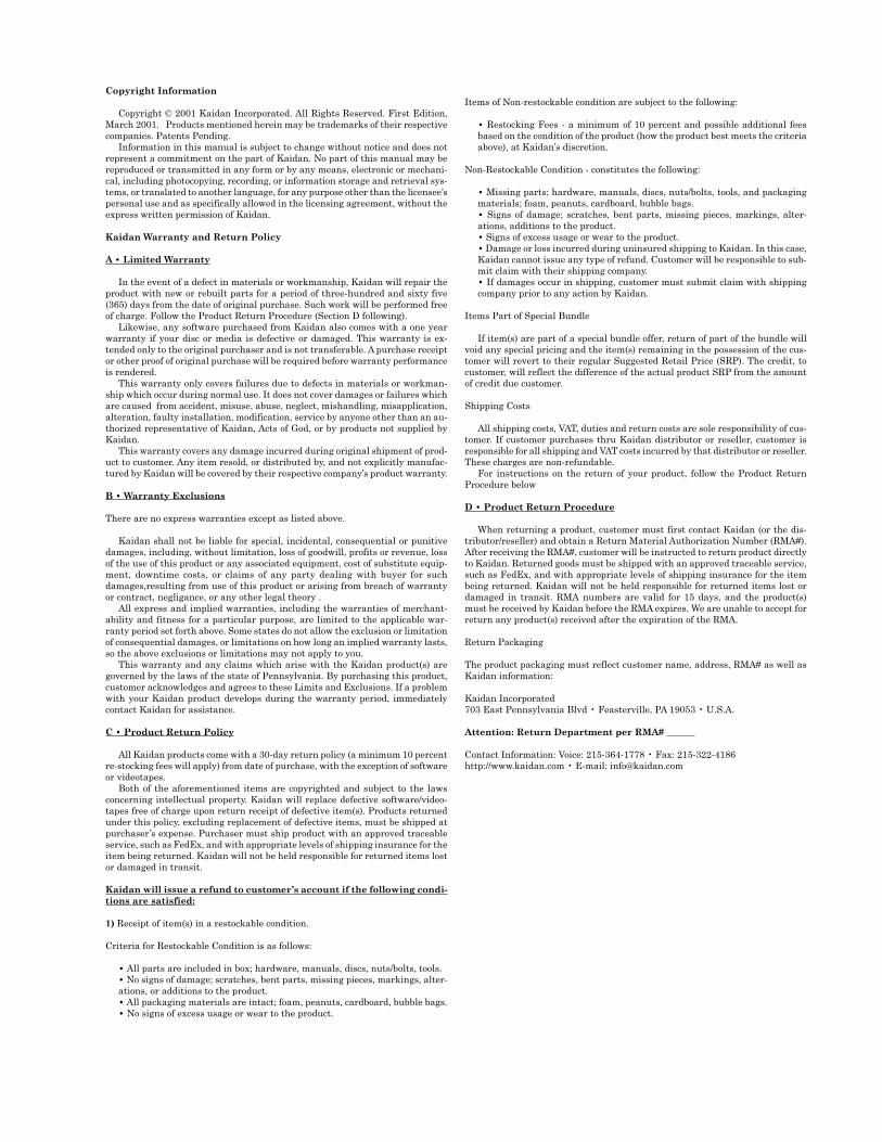
Assembling the KiWi™
UNPACKING THE BOX
The KiWi-L or the Kiwi + are shipped in a single box and con-sists of two major components. The components are detailedbelow. NOTE: Only the Kiwi+ is shipped with four detent discs(12,14,18, and 20 positions). Please make sure that all partsare included. Examine the parts for any signs of shipping dam-age. In the event of shipping damage, immediately contactKaidan to process claims.If any items are missing or you notice any damage, call Kaidanat 215-364-1778, between the hours of 10:00 am and 6:00 PM,Mon-Fri, EST.
Twin-Axis Bubble Level
Vertical BracketFore-aft Indicator
Camera Adj. Shoe KnobCaptive Camera Knob
Side-to-Side Indicator
Horizontal Bracket
Kiwi +
Kiwi-L
Vertical BracketFore-aft Indicator
Camera Adj. Shoe KnobCaptive Camera Knob
Twin-Axis Bubble Level
Side-to-Side IndicatorHorizontal Bracket
Locking Knob
Friction Cap
1
Page - 4
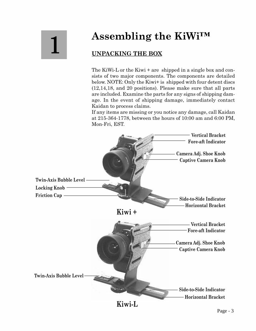
Assembling the KiWi ™
ATTACHING THE VERTICAL BRACKET
To assemble the KiWi, simply slide the Vertical Bracket onto theHorizontal Bracket in the orientation shown in the various im-ages in this manual. Note: The bottom of the Vertical Brackethas a clamping mechanism with a spring-loaded nylon ball whichkeeps tension on the horizontal bracket while sliding the verticalbracket back and forth. Before installing the Vertical Bracketonto the Horizontal Bracket, make sure the Purple ClampingKnob is turned all the way out in a counterclockwise direction,which will release the clamping mechanism inside the bottom ofthe Vertical Bracket. When attaching the Vertical Bracket tothe Horizontal Bracket, some force will be required initially toovercome the tension of the spring-loaded ball in the bottom ofthe Vertical Bracket.
Slide Vertical Bracketonto Horizontal Bracket
Purple Clamping Knob
Page - 5
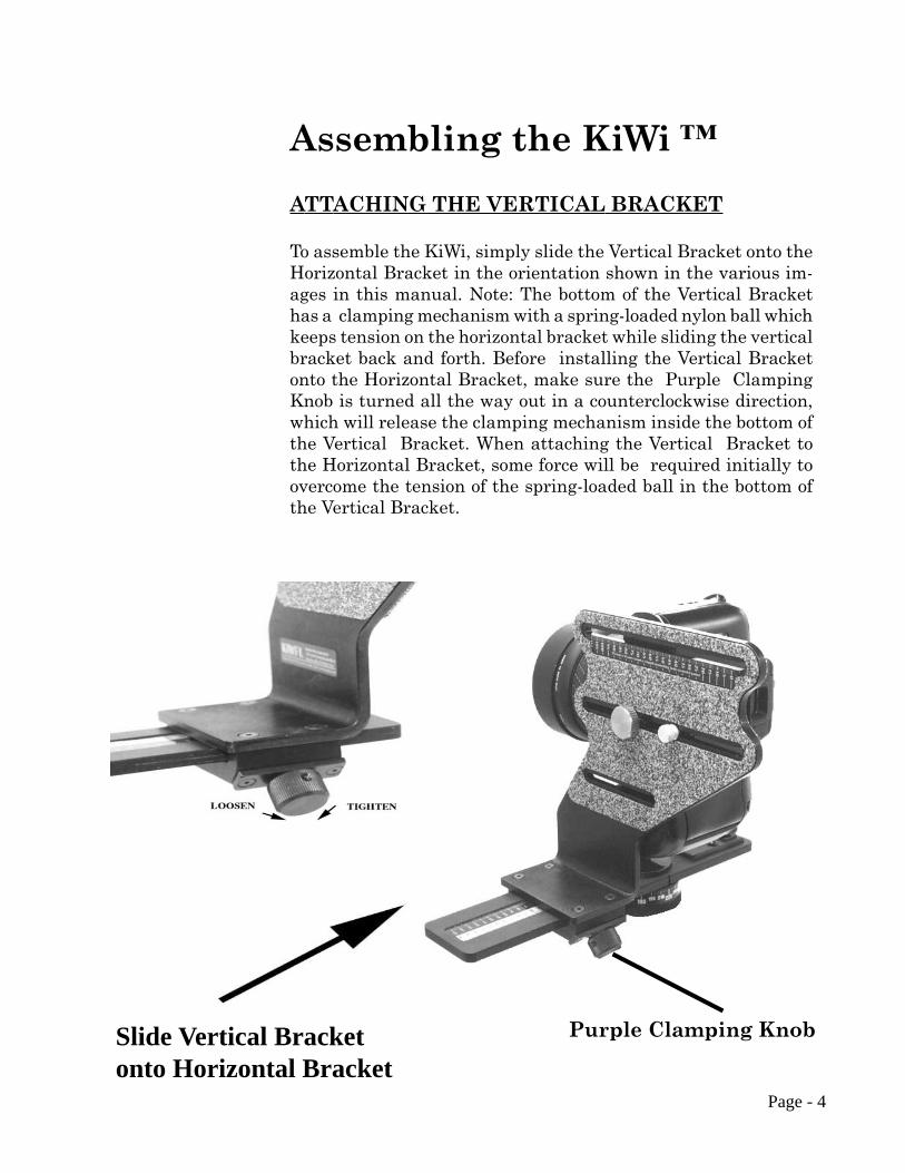
Using the KiWi™
ATTACHING YOUR CAMERATo mount your camera, first select the appropriate slot in theVertical Bracket that will best locate the tripod mounting threadon your camera. You may need to reposition the Captive CameraKnob in order to achieve this. To remove the knob simply slidethe knob along the slot to the end that has the threaded hole.Carefully unscrew the knob out of the threaded hole, being care-ful not to crossthread the knob. Replace the knob into the appro-priate slot by reversing the procedure. Note: Whatever side ofthe Vertical Bracket you mount your camera on always keep theoffset portion of the Vertical Bracket towards the rear of the cam-era. Attach your camera by threading the knob into the threadedtripod hole of your camera. Note: The camera knob is a two pieceknob, (not shown), with a inner and outer knob. Before installingthe camera knob in the Vertical Bracket, turn the inner knobclockwise into the outer knob until it won’t turn anymore. Nextinstall the knob into the appropriate slot then into the tripodmounting hole of your camera. Turn the inner knob into the cam-era until it bottoms out, then turn the outer knob clockwise untilthe camera is tight on the Vertical Bracket. Don’t worry aboutgetting the camera level at this time, as this is a task you’ll needto do when you’re ready to shoot. Note:If you have a large bodycamera that has very long distance from the tripod mountingsurface to the center of the lens, the Vertical Bracket might haveto mounted on the Horizontal the reverseof how it is shown below withthe camera facing in the otherdirection.
Captive Camera Knob
Threaded Hole ( 1 of 3 )
Camera Shoe Adj. Knob
Offset towards rear of camera
Saddle Clamp LockingKnob
2

Page - 6
Using the KiWi™
REMOVING THE FRICTION CAP
The KiWi+ needs to be disassembled in order to install or changedetent discs. The detent discs come in various settings and pro-vide the different angular click-stops. (NOTE: See Disc Selec-tion Chart In Appendix A).
To start, the friction cap must be removed. Loosen the knoblocated on the side of the friction cap. It does not have to beremoved from the cap, but just backed out far enough so thatthe cap can be unscrewed from the axle. Unscrew the cap. At-tached to the cap is a rubber washer with a nylon facing.
Page - 7
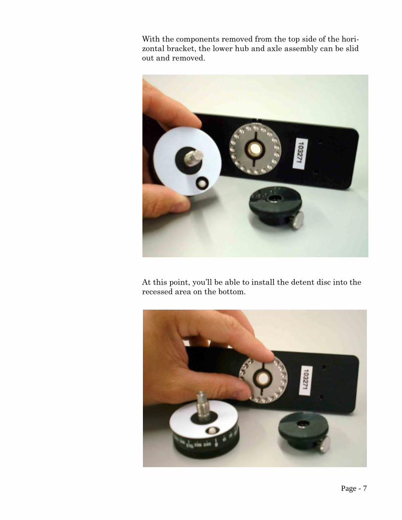
With the components removed from the top side of the hori-zontal bracket, the lower hub and axle assembly can be slidout and removed.
At this point, you’ll be able to install the detent disc into therecessed area on the bottom.
Page - 8
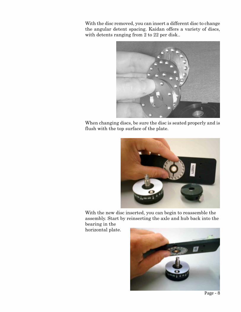
With the disc removed, you can insert a different disc to changethe angular detent spacing. Kaidan offers a variety of discs,with detents ranging from 2 to 22 per disk..
When changing discs, be sure the disc is seated properly and isflush with the top surface of the plate.
With the new disc inserted, you can begin to reassemble theassembly. Start by reinserting the axle and hub back into thebearing in thehorizontal plate.

Page - 9
Push the axle through the bearing and plate as shown below.Reverse the disassembly.
Replace the cap by threading the cap onto the axle as shownbelow. Continue to thread the cap so that there is no free playin any of the pieces and to compress the rubber washerslightly.
When the friction drag feels adequate, turn the Friction capso that the knob is aligned with one of the flats on the axle.Tighten the knob to lock.
Page - 10
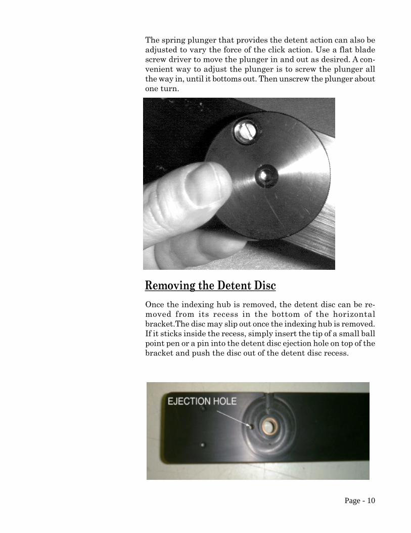
The spring plunger that provides the detent action can also beadjusted to vary the force of the click action. Use a flat bladescrew driver to move the plunger in and out as desired. A con-venient way to adjust the plunger is to screw the plunger allthe way in, until it bottoms out. Then unscrew the plunger aboutone turn.
Once the indexing hub is removed, the detent disc can be re-moved from its recess in the bottom of the horizontalbracket.The disc may slip out once the indexing hub is removed.If it sticks inside the recess, simply insert the tip of a small ballpoint pen or a pin into the detent disc ejection hole on top of thebracket and push the disc out of the detent disc recess.
Removing the Detent Disc
Page - 11
Using the KiWi™HOW DO I LOCATE MY NODAL POINT ?
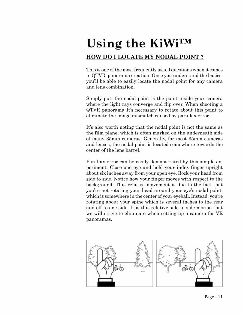
This is one of the most frequently asked questions when it comesto QTVR panorama creation. Once you understand the basics,you’ll be able to easily locate the nodal point for any cameraand lens combination.
Simply put, the nodal point is the point inside your camerawhere the light rays converge and flip over. When shooting aQTVR panorama It’s necessary to rotate about this point toeliminate the image mismatch caused by parallax error.
It’s also worth noting that the nodal point is not the same asthe film plane, which is often marked on the underneath sideof many 35mm cameras. Generally, for most 35mm camerasand lenses, the nodal point is located somewhere towards thecenter of the lens barrel.
Parallax error can be easily demonstrated by this simple ex-periment. Close one eye and hold your index finger uprightabout six inches away from your open eye. Rock your head fromside to side. Notice how your finger moves with respect to thebackground. This relative movement is due to the fact thatyou’re not rotating your head around your eye’s nodal point,which is somewhere in the center of your eyeball. Instead, you’rerotating about your spine which is several inches to the rearand off to one side. It is this relative side-to-side motion thatwe will strive to eliminate when setting up a camera for VRpanoramas.
STEP 1: THE
EASY PART -THE SIDE-TO-SIDE
ADJUSTMENT
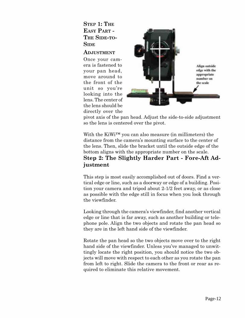
Once your cam-era is fastened toyour pan head,move around tothe front of theunit so you’relooking into thelens. The center ofthe lens should bedirectly over thepivot axis of the pan head. Adjust the side-to-side adjustmentso the lens is centered over the pivot.
With the KiWi™ you can also measure (in millimeters) thedistance from the camera’s mounting surface to the center ofthe lens. Then, slide the bracket until the outside edge of thebottom aligns with the appropriate number on the scale.Step 2: The Slightly Harder Part - Fore-Aft Ad-justment
This step is most easily accomplished out of doors. Find a ver-tical edge or line, such as a doorway or edge of a building. Posi-tion your camera and tripod about 2-1/2 feet away, or as closeas possible with the edge still in focus when you look throughthe viewfinder.
Looking through the camera’s viewfinder, find another verticaledge or line that is far away, such as another building or tele-phone pole. Align the two objects and rotate the pan head sothey are in the left hand side of the viewfinder.
Rotate the pan head so the two objects move over to the righthand side of the viewfinder. Unless you’ve managed to unwit-tingly locate the right position, you should notice the two ob-jects will move with respect to each other as you rotate the panfrom left to right. Slide the camera to the front or rear as re-quired to eliminate this relative movement.
Page-12

Page - 13
It may help to first locate the camera all the way to the frontor rear and then move it a little bit at a time. This way you’llmore readily see the parallax effect and notice how it im-
proves as you slide the bracket.
STEP 3: LEVEL THE CAMERA
Once you have located the fore-aft position, you now must levelthe camera. If your camera has a flash hot shoe, you can use abubble level designed to slide into the shoe. You should be ableto get these at a good photographic supply store. Kaidan alsohas these levels for sale at competitive prices.
If your camera does not have a hot shoe, then you’ll need tolevel the camera another way. If the camera has a flat, level
Looking throughthe viewfinderalign a close ob-ject (brick wall)with a farawayobject (telephonepole). As you ro-tate the camerafrom side-to-sidethere should beno relative move-ment between thetwo objects asshown to theright.
If, as shown to theright, the twoobjects move withrespect to one andanother in theviewinder, slidethe camera fore oraft in order toeliminate thismovement. Here,the telephone polehas moved behindthe brick wall.

Page - 14
surface, then you can use a bubble level. You should be able tolocate a small level at a hardware store. If your there are nolevel surfaces, then you may have to resort to “eyeballing”.
STEP 4: RECORD YOUR RESULTS
After you’ve discovered the two location dimensions, be sure torecord the settings. The KiWi has convenient indicator scalesfor this purpose. These numbers represent the nodal point forthis given camera and lens combination. If you change cam-eras or lenses, this procedure may have to be repeated.
STEP 5: HOW ABOUT RANGEFINDER CAMERAS?
A rangefinder camera is a camera where you look through aseparate viewfinder and not through the actual lens. The pro-cess is basically the same. Locate the Side-to-Side adjustmentas discussed in Step 1. When it comes to the Fore-Aft adjust-ment, you won’t be able to look through the viewfinder to de-termine the proper setting since the viewfinder is a separateoptical path that doesn’t really “see” the same image as thefilm.
Instead, you’ll have to start with the bracket all the way to thefront and take pairs of test shots. Each pair will have the verti-cally aligned objects in the left and then the right side of theviewfinder. After each pair of photos, slide the bracket rear-ward and repeat the process. Slide the bracket the same incre-ment each time (i.e. 10mm). Be sure to record the scale settingfor each pair of images. Process the film, or in the case of digi-tal cameras, download the images to your computer.
At the end of this process you will be able locate the pair ofimages with the least relative movement. If no single image isoptimum, you may need to interpolate between two images tofind the closest value.
Page - 15
TAKING PHOTOS WITH THE KIWI™
HOW MUCH OVERLAP?
The amount you turn the camera for each shot varies. It isdependent on a number of factors such as the field of view (theangle) of your camera and lens, as well as which program youintend to use. For example, Apple recommends that the im-ages should overlap by anywhere from one-third to one-half.You should check with the recommendations of the softwarethat you intend to use in order to determine overlap require-ments.
HOW MANY SHOTS?
Once you’ve determined the overlap, you’ll be able to figure outhow many shots. The easiest way to do this is to simply lookthrough the viewfinder and turn the camera to achieve the de-sired amount of overlap. You then check the angle readout tosee how far you turned the camera. Round the angular value tothe nearest convenient value. For most stitching programs, itis generally not that important to use a precise overlap value.
However, it should be noted that some programs are more sen-sitive to an overlap value that constantly repeats from shot toshot. You may need to experiment somewhat to obtain the bestresults.
TAKING THE PHOTOS
When you’re ready to shoot, make sure that the camera andKiWi™ are securely attached. You should use a tripod that issturdy, ideally one that has a center support system of bracesto help keep the camera and KiWi™ from flexing.
Proper leveling is important. We discussed earlier, the processfor leveling the camera in elevation (looking up and down onthe Vertical Bracket), now that you’re ready to shoot, it is im-portant that the rotation plane of the camera is level as well.
3
Page - 16
TAKING THE PHOTOS (CONTINUED).You can use the level on your KiWi™ and observe it while youlevel the tripod. Of course, this task is much easier if your tri-pod also has a tilt head.
Once the tripod and KiWi™ are level, now is the time to doublecheck to see if the camera is straight up and down. If it needsto be adjusted, loosen the Captive knob just a slight amountand tilt the camera accordingly. Be sure not to change the Fore-Aft dimension. Tighten the Captive knob.
If your using the KiWi-L rotate the camera so that the grooveon the Horizontal Bracket aligns with the zero point on thecircular barrel. Depending on whether the stitching softwarethat you’re using prefers the having the photos taken in a clock-wise or counterclockwise sequence, you’ll have to either countdown from 360 degrees or count-up from zero degrees.
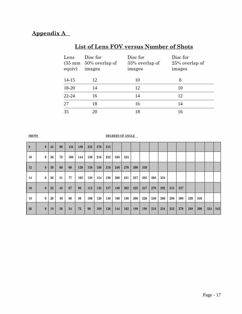
NOTE: Starting with KiWi™-L units produced after July 1,1997, we have added a bonus Label Sheet. This set containsself-adhesive labels with the popular degree increments. Sincethere are no other markings, the labels make it easy to rotateand stop at the correct position for your particular camera andlens combination.There is a “List of Lens FOV versus Numberof Shots” chart and a “Degrees of Angle” chart in Appendix A.
As you shoot around the circle, try to avoid capturing any mov-ing objects that might come into your field of view. There is noharm in waiting, for example, while a person walks past beforeshooting the photo.
You may also want to check with the software developer of thestitching software that you’re using to get their recommenda-tions for exposure settings and other camera settings.
We hope you enjoy shooting your panoramas and if you haveany questions or problems using our equipment, please let usknow. We would also like to see the results of your work andwould be glad to consider placing your work on our website, orto put a link to your website as well.
Thank you,The Kaidan team.
Page - 17
Appendix A
List of Lens FOV versus Number of Shots
Lens(35 mmequiv)
14-15 12 10 8
18-20 14 12 10
22-24 16 14 12
27 18 16 14
35 20 18 16
Disc for50% overlap ofimages
Disc for33% overlap ofimages
Disc for25% overlap ofimages
SHOTS DEGREES OF ANGLE
8 0 45 90 135 180 225 270 315
10 0 36 72 108 144 180 216 252 288 324
12 0 30 60 60 120 150 180 210 240 270 300 330
14 0 26 51 77 103 128 154 180 206 231 257 283 308 334
16 0 22 45 67 90 112 135 157 180 202 225 247 270 292 315 337
18 0 20 40 60 80 100 120 140 160 180 200 220 240 260 280 300 320 340
20 0 18 36 54 72 90 108 126 144 162 180 198 216 234 252 270 288 306 324 342
Page - 18
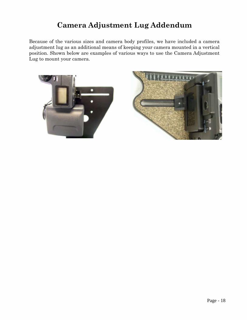
Camera Adjustment Lug Addendum
Because of the various sizes and camera body profiles, we have included a cameraadjustment lug as an additional means of keeping your camera mounted in a verticalposition. Shown below are examples of various ways to use the Camera AdjustmentLug to mount your camera.