instantaneous loopinstantaneoustech.com/wp-content/uploads/files/instantaneous loop.pdfintellectual...
TRANSCRIPT
Instantaneous Loop Ideal Phase Locked Loop
Gain ICs
2
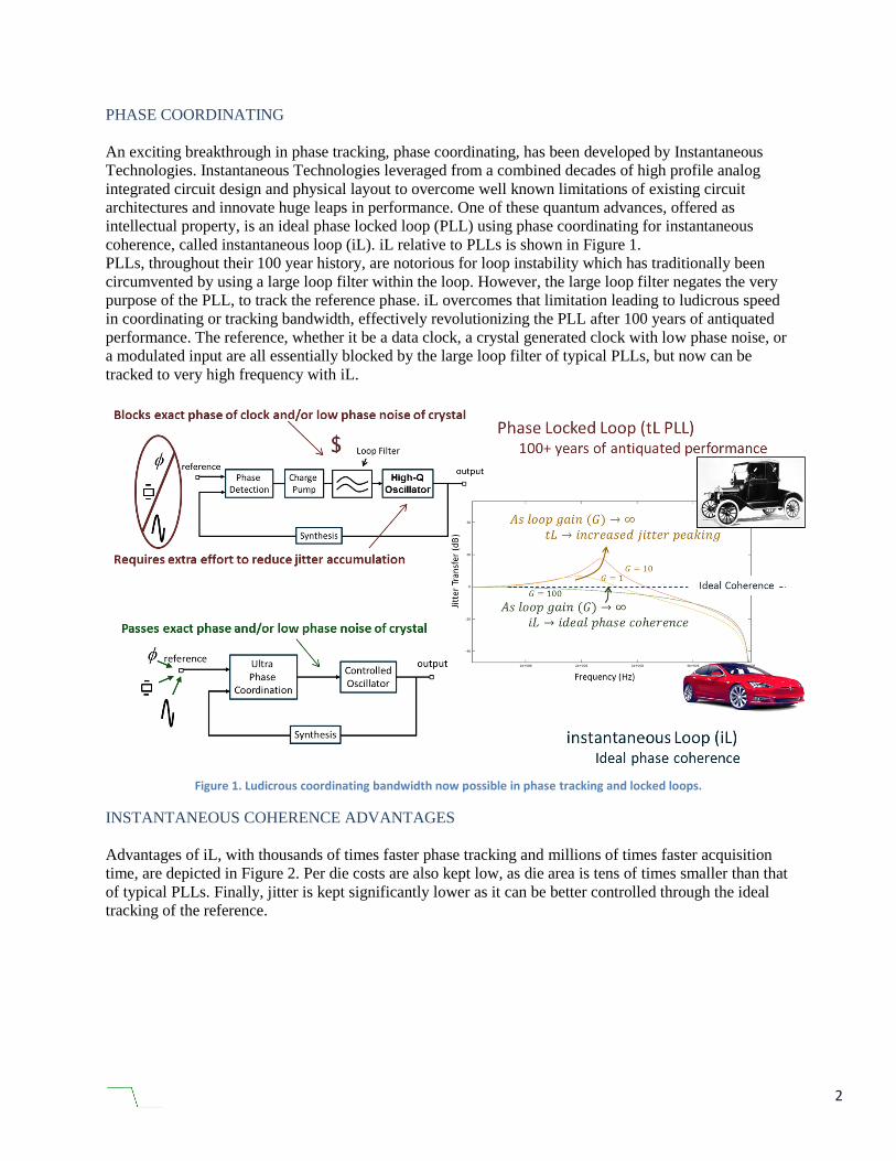
PHASE COORDINATING
An exciting breakthrough in phase tracking, phase coordinating, has been developed by Instantaneous
Technologies. Instantaneous Technologies leveraged from a combined decades of high profile analog
integrated circuit design and physical layout to overcome well known limitations of existing circuit
architectures and innovate huge leaps in performance. One of these quantum advances, offered as
intellectual property, is an ideal phase locked loop (PLL) using phase coordinating for instantaneous
coherence, called instantaneous loop (iL). iL relative to PLLs is shown in Figure 1.
PLLs, throughout their 100 year history, are notorious for loop instability which has traditionally been
circumvented by using a large loop filter within the loop. However, the large loop filter negates the very
purpose of the PLL, to track the reference phase. iL overcomes that limitation leading to ludicrous speed
in coordinating or tracking bandwidth, effectively revolutionizing the PLL after 100 years of antiquated
performance. The reference, whether it be a data clock, a crystal generated clock with low phase noise, or
a modulated input are all essentially blocked by the large loop filter of typical PLLs, but now can be
tracked to very high frequency with iL.
Figure 1. Ludicrous coordinating bandwidth now possible in phase tracking and locked loops.
INSTANTANEOUS COHERENCE ADVANTAGES
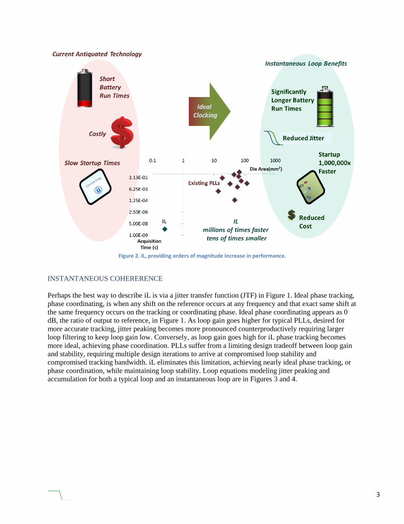
Advantages of iL, with thousands of times faster phase tracking and millions of times faster acquisition
time, are depicted in Figure 2. Per die costs are also kept low, as die area is tens of times smaller than that
of typical PLLs. Finally, jitter is kept significantly lower as it can be better controlled through the ideal
tracking of the reference.
3
Figure 2. iL, providing orders of magnitude increase in performance.
INSTANTANEOUS COHERERENCE
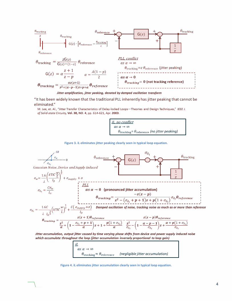
Perhaps the best way to describe iL is via a jitter transfer function (JTF) in Figure 1. Ideal phase tracking,
phase coordinating, is when any shift on the reference occurs at any frequency and that exact same shift at
the same frequency occurs on the tracking or coordinating phase. Ideal phase coordinating appears as 0
dB, the ratio of output to reference, in Figure 1. As loop gain goes higher for typical PLLs, desired for
more accurate tracking, jitter peaking becomes more pronounced counterproductively requiring larger
loop filtering to keep loop gain low. Conversely, as loop gain goes high for iL phase tracking becomes
more ideal, achieving phase coordination. PLLs suffer from a limiting design tradeoff between loop gain
and stability, requiring multiple design iterations to arrive at compromised loop stability and
compromised tracking bandwidth. iL eliminates this limitation, achieving nearly ideal phase tracking, or
phase coordination, while maintaining loop stability. Loop equations modeling jitter peaking and
accumulation for both a typical loop and an instantaneous loop are in Figures 3 and 4.
4
Figure 3. iL eliminates jitter peaking clearly seen in typical loop equation.
Figure 4. iL eliminates jitter accumulation clearly seen in typical loop equation.
5
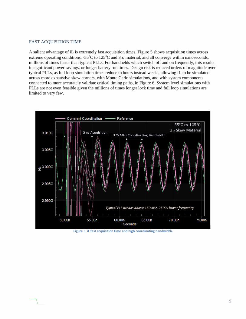
FAST ACQUISITION TIME
A salient advantage of iL is extremely fast acquisition times. Figure 5 shows acquisition times across
extreme operating conditions, -55oC to 125
oC and 3 material, and all converge within nanoseconds,
millions of times faster than typical PLLs. For handhelds which switch off and on frequently, this results
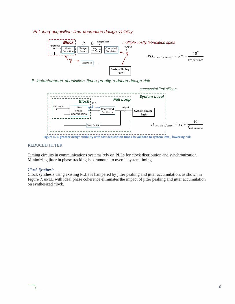
in significant power savings, or longer battery run times. Design risk is reduced orders of magnitude over
typical PLLs, as full loop simulation times reduce to hours instead weeks, allowing iL to be simulated
across more exhaustive skew corners, with Monte Carlo simulations, and with system components
connected to more accurately validate critical timing paths, in Figure 6. System level simulations with
PLLs are not even feasible given the millions of times longer lock time and full loop simulations are
limited to very few.
Figure 5. iL fast acquisition time and high coordinating bandwidth.
6
Figure 6. iL greater design visibility with fast acquisition times to validate to system level, lowering risk.
REDUCED JITTER
Timing circuits in communications systems rely on PLLs for clock distribution and synchronization.
Minimizing jitter in phase tracking is paramount to overall system timing.
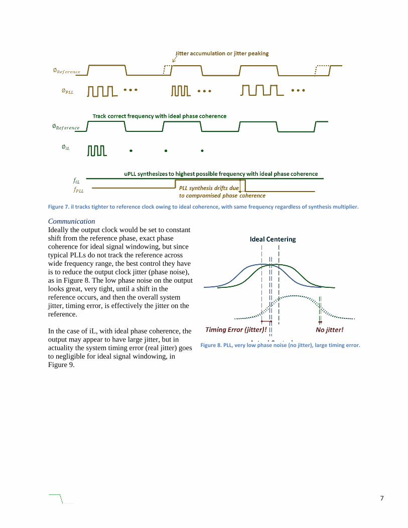
Clock Synthesis
Clock synthesis using existing PLLs is hampered by jitter peaking and jitter accumulation, as shown in
Figure 7. uPLL with ideal phase coherence eliminates the impact of jitter peaking and jitter accumulation
on synthesized clock.
7
Figure 7. il tracks tighter to reference clock owing to ideal coherence, with same frequency regardless of synthesis multiplier.
Communication
Ideally the output clock would be set to constant
shift from the reference phase, exact phase
coherence for ideal signal windowing, but since
typical PLLs do not track the reference across
wide frequency range, the best control they have
is to reduce the output clock jitter (phase noise),
as in Figure 8. The low phase noise on the output
looks great, very tight, until a shift in the
reference occurs, and then the overall system
jitter, timing error, is effectively the jitter on the
reference.
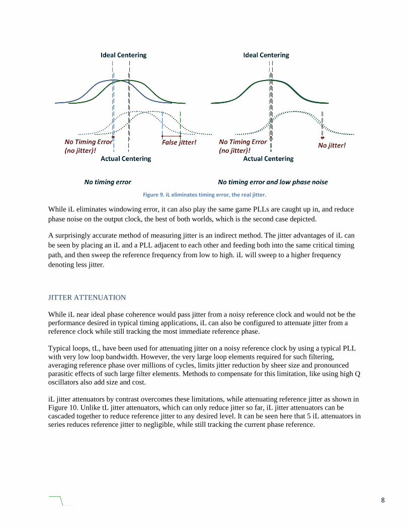
In the case of iL, with ideal phase coherence, the
output may appear to have large jitter, but in
actuality the system timing error (real jitter) goes
to negligible for ideal signal windowing, in
Figure 9.
Figure 8. PLL, very low phase noise (no jitter), large timing error.
8
Figure 9. iL eliminates timing error, the real jitter.
While iL eliminates windowing error, it can also play the same game PLLs are caught up in, and reduce
phase noise on the output clock, the best of both worlds, which is the second case depicted.
A surprisingly accurate method of measuring jitter is an indirect method. The jitter advantages of iL can
be seen by placing an iL and a PLL adjacent to each other and feeding both into the same critical timing
path, and then sweep the reference frequency from low to high. iL will sweep to a higher frequency
denoting less jitter.
JITTER ATTENUATION
While iL near ideal phase coherence would pass jitter from a noisy reference clock and would not be the
performance desired in typical timing applications, iL can also be configured to attenuate jitter from a
reference clock while still tracking the most immediate reference phase.
Typical loops, tL, have been used for attenuating jitter on a noisy reference clock by using a typical PLL
with very low loop bandwidth. However, the very large loop elements required for such filtering,
averaging reference phase over millions of cycles, limits jitter reduction by sheer size and pronounced
parasitic effects of such large filter elements. Methods to compensate for this limitation, like using high Q
oscillators also add size and cost.
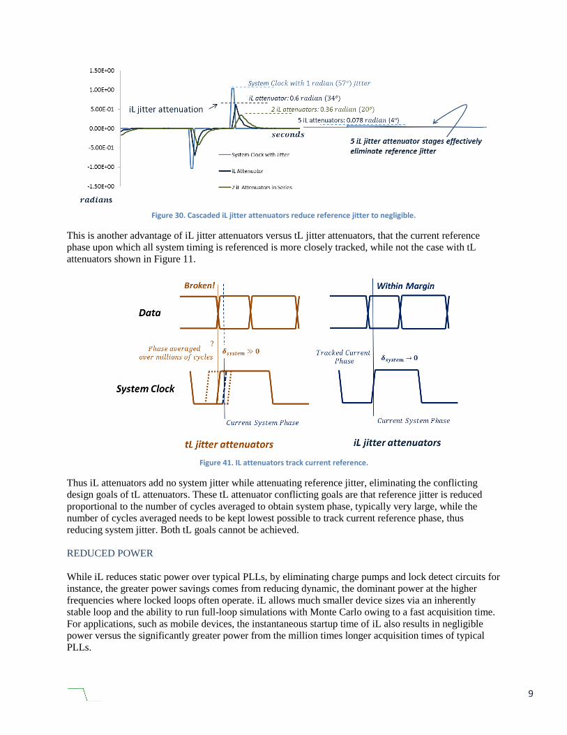
iL jitter attenuators by contrast overcomes these limitations, while attenuating reference jitter as shown in
Figure 10. Unlike tL jitter attenuators, which can only reduce jitter so far, iL jitter attenuators can be
cascaded together to reduce reference jitter to any desired level. It can be seen here that 5 iL attenuators in
series reduces reference jitter to negligible, while still tracking the current phase reference.
9
Figure 30. Cascaded iL jitter attenuators reduce reference jitter to negligible.
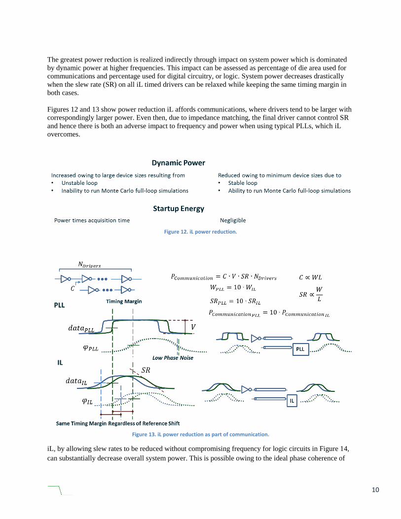
This is another advantage of iL jitter attenuators versus tL jitter attenuators, that the current reference
phase upon which all system timing is referenced is more closely tracked, while not the case with tL
attenuators shown in Figure 11.
Figure 41. IL attenuators track current reference.
Thus iL attenuators add no system jitter while attenuating reference jitter, eliminating the conflicting
design goals of tL attenuators. These tL attenuator conflicting goals are that reference jitter is reduced
proportional to the number of cycles averaged to obtain system phase, typically very large, while the
number of cycles averaged needs to be kept lowest possible to track current reference phase, thus
reducing system jitter. Both tL goals cannot be achieved.
REDUCED POWER
While iL reduces static power over typical PLLs, by eliminating charge pumps and lock detect circuits for
instance, the greater power savings comes from reducing dynamic, the dominant power at the higher
frequencies where locked loops often operate. iL allows much smaller device sizes via an inherently
stable loop and the ability to run full-loop simulations with Monte Carlo owing to a fast acquisition time.
For applications, such as mobile devices, the instantaneous startup time of iL also results in negligible
power versus the significantly greater power from the million times longer acquisition times of typical
PLLs.
10
The greatest power reduction is realized indirectly through impact on system power which is dominated
by dynamic power at higher frequencies. This impact can be assessed as percentage of die area used for
communications and percentage used for digital circuitry, or logic. System power decreases drastically
when the slew rate (SR) on all iL timed drivers can be relaxed while keeping the same timing margin in
both cases.
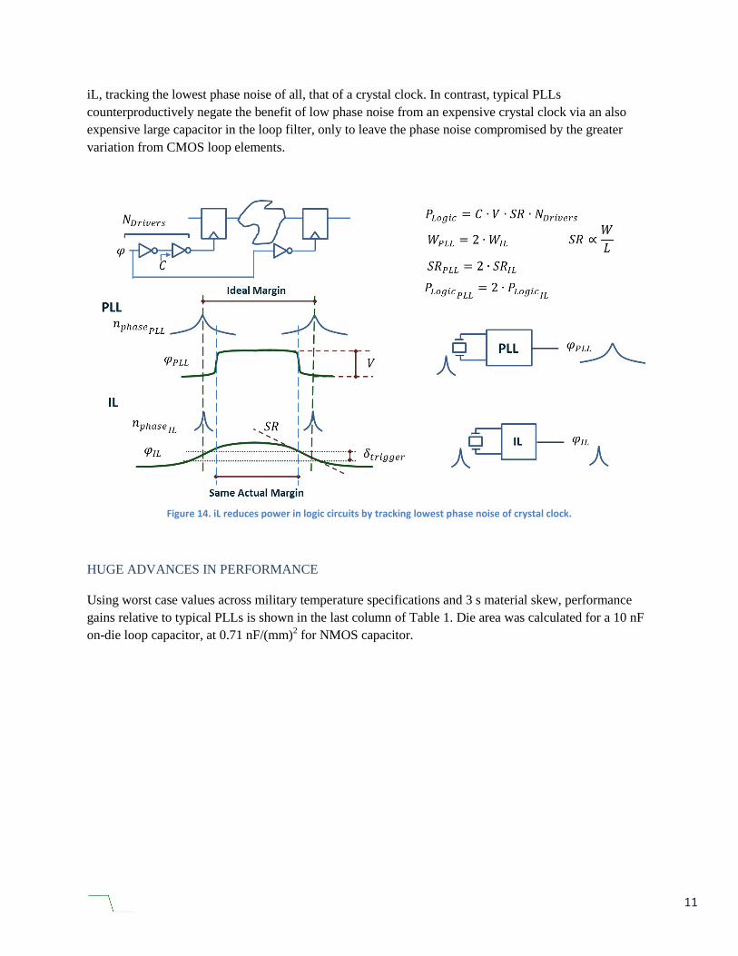
Figures 12 and 13 show power reduction iL affords communications, where drivers tend to be larger with
correspondingly larger power. Even then, due to impedance matching, the final driver cannot control SR
and hence there is both an adverse impact to frequency and power when using typical PLLs, which iL
overcomes.
Figure 12. iL power reduction.
Figure 13. iL power reduction as part of communication.
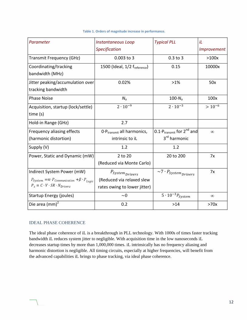
iL, by allowing slew rates to be reduced without compromising frequency for logic circuits in Figure 14,
can substantially decrease overall system power. This is possible owing to the ideal phase coherence of
11
iL, tracking the lowest phase noise of all, that of a crystal clock. In contrast, typical PLLs
counterproductively negate the benefit of low phase noise from an expensive crystal clock via an also
expensive large capacitor in the loop filter, only to leave the phase noise compromised by the greater
variation from CMOS loop elements.
Figure 14. iL reduces power in logic circuits by tracking lowest phase noise of crystal clock.
HUGE ADVANCES IN PERFORMANCE
Using worst case values across military temperature specifications and 3 s material skew, performance
gains relative to typical PLLs is shown in the last column of Table 1. Die area was calculated for a 10 nF
on-die loop capacitor, at 0.71 nF/(mm)2 for NMOS capacitor.
12
Table 1. Orders of magnitude increase in performance.
Parameter Instantaneous Loop
Specification
Typical PLL iL
Improvement
Transmit Frequency (GHz) 0.003 to 3 0.3 to 3 >100x
Coordinating/tracking
bandwidth (MHz)
1500 (Ideal, 1/2 freference) 0.15 10000x
Jitter peaking/accumulation over
tracking bandwidth
0.02% >1% 50x
Phase Noise No 100·No 100x
Acquisition, startup (lock/settle)
time (s)
2 ∙ 10−9 2 ∙ 10−3 > 10−6
Hold-in Range (GHz) 2.7
Frequency aliasing effects
(harmonic distortion)
0·Ptransmit all harmonics,
intrinsic to iL
0.1·Ptransmit for 2nd and
3rd harmonic
Supply (V) 1.2 1.2
Power, Static and Dynamic (mW) 2 to 20
(Reduced via Monte Carlo)
20 to 200 7x
Indirect System Power (mW)
𝑃𝑆𝑦𝑠𝑡𝑒𝑚𝐷𝑟𝑖𝑣𝑒𝑟𝑠
(Reduced via relaxed slew
rates owing to lower jitter)
~7 ∙ 𝑃𝑆𝑦𝑠𝑡𝑒𝑚𝐷𝑟𝑖𝑣𝑒𝑟𝑠 7x
Startup Energy (joules) ~0 5 ∙ 10−3𝑃𝑆𝑦𝑠𝑡𝑒𝑚
Die area (mm)2 0.2 >14 >70x
IDEAL PHASE COHERENCE
The ideal phase coherence of iL is a breakthrough in PLL technology. With 1000s of times faster tracking
bandwidth iL reduces system jitter to negligible. With acquisition time in the low nanoseconds iL
decreases startup times by more than 1,000,000 times. iL intrinsically has no frequency aliasing and
harmonic distortion is negligible. All timing circuits, especially at higher frequencies, will benefit from
the advanced capabilities iL brings to phase tracking, via ideal phase coherence.