instantaneous and 3-phase power - chatziva
TRANSCRIPT

Spyros Chatzivasileiadis
31730: Electric Power Engineering, fundamentals
Instantaneous and 3-phase power
8 September 2017
If not otherwise indicated, all figures are taken from the course textbook: J. D. Glover, T. J. Overbye, M. S. Sarma, Power System Analysis and Design, Sixth Edition - SI, Cengage Learning, 2016

DTU Electrical Engineering, Technical University of Denmark
Reviewing previous lecture
2
• For 5 minutes discuss with the person sitting next to you about:
– Three main points we discussed in the last lecture
– One topic or concept that is not so clear and you would like to hear again about it
Spyros Chatzivasileiadis

DTU Electrical Engineering, Technical University of Denmark
The goals for today• Instantaneous active and reactive power
• Power factor and complex power
• Line-to-neutral and line-to-line voltage
• Δ-loads and Y-loads
• Single-line diagram
• Power in three-phase balanced systems
3 Spyros Chatzivasileiadis

DTU Electrical Engineering, Technical University of Denmark
Instantaneous power• On the board
4 Spyros Chatzivasileiadis

DTU Electrical Engineering, Technical University of Denmark
Phasor Diagrams
5
Z
Re
Im
Z=R
Z=jXC
Z=jXL
IIm
I=IR
I=IL
I=Ic
PowerIm
Q=PR
S=jQC
S=jQL
Re Re
• Inductive Character:– Current lags the voltage– Q consumed; Q>0 (for loads)
• Capacitive Character:– Current leads the voltage– Q produced; Q<0 (for loads)
Spyros Chatzivasileiadis

DTU Electrical Engineering, Technical University of Denmark
Conventions: Positive and negative P and Q
6 Spyros Chatzivasileiadis

DTU Electrical Engineering, Technical University of Denmark
Balanced three-phase systems
7
• Voltage line-to-neutral
• Voltage line-to-line
• Question:What are the phasors for the line to neutral voltages?(for each phase)
Spyros Chatzivasileiadis

DTU Electrical Engineering, Technical University of Denmark
Balanced three-phase systems
8
• Voltage line-to-neutral
• Voltage line-to-line
• Assuming a 𝑉"#$ = 10for each phase:
• Question:What are the phasors for the line-to-line voltages?(for each phase)
S = V · I∗
ZY =Z∆
3
p3φ(t) = P3φ = 3VLNIL cos(δ − β)
Ean = 10 0◦
Ebn = 10 −120◦
Ecn = 10 +120◦
7 DTU Electrical Engineering 31730: Electric Power Engineering, Fundamentals Sep 8, 2017
Spyros Chatzivasileiadis

DTU Electrical Engineering, Technical University of Denmark
Line-to-neutral and line-to-line voltages
9 Spyros Chatzivasileiadis

DTU Electrical Engineering, Technical University of Denmark
Delta-Wye Loads and transformation
10
S = V · I∗
ZY =Z∆
3
p3φ(t) = pa(t) + pb(t) + pc(t) =
3VLNIL cos(δ − β) + VLNIL[cos(2ωt+ δ + β)
cos(2ωt+ δ + β − 240◦)+ cos(2ωt+ δ + β + 240◦)]
7 DTU Electrical Engineering 31730: Electric Power Engineering, Fundamentals Sep 8, 2017
Spyros Chatzivasileiadis

DTU Electrical Engineering, Technical University of Denmark
Three-phase to single line diagram
11 Spyros Chatzivasileiadis

DTU Electrical Engineering, Technical University of Denmark
Three-phase to single line diagram
12
• Three main points:
1. Voltages must be RMS values
2. Transform line-to-line voltages to line-to-neutral
3. Transform all Δ-loads to Y-loads
Spyros Chatzivasileiadis
DTU Electrical Engineering, Technical University of Denmark
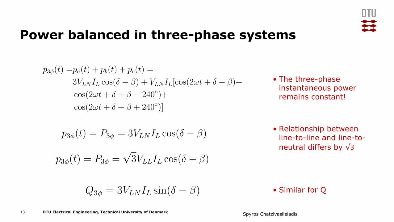
Power balanced in three-phase systems
• The three-phase instantaneous power remains constant!
• Relationship between line-to-line and line-to-neutral differs by √3
• Similar for Q
13
S = V · I∗
ZY =Z∆
3
p3φ(t) =pa(t) + pb(t) + pc(t) =
3VLNIL cos(δ − β) + VLNIL[cos(2ωt+ δ + β)+
cos(2ωt+ δ + β − 240◦)+
cos(2ωt+ δ + β + 240◦)]
p3φ(t) = P3φ = 3VLNIL cos(δ − β)
p3φ(t) = P3φ =√3VLLIL cos(δ − β)
7 DTU Electrical Engineering 31730: Electric Power Engineering, Fundamentals Sep 8, 2017
S = V · I∗
ZY =Z∆
3
p3φ(t) =pa(t) + pb(t) + pc(t) =
3VLNIL cos(δ − β) + VLNIL[cos(2ωt+ δ + β)+
cos(2ωt+ δ + β − 240◦)+
cos(2ωt+ δ + β + 240◦)]
p3φ(t) = P3φ = 3VLNIL cos(δ − β)
p3φ(t) = P3φ =√3VLLIL cos(δ − β)
7 DTU Electrical Engineering 31730: Electric Power Engineering, Fundamentals Sep 8, 2017
S = V · I∗
ZY =Z∆
3
p3φ(t) =pa(t) + pb(t) + pc(t) =
3VLNIL cos(δ − β) + VLNIL[cos(2ωt+ δ + β)+
cos(2ωt+ δ + β − 240◦)+
cos(2ωt+ δ + β + 240◦)]
p3φ(t) = P3φ = 3VLNIL cos(δ − β)
p3φ(t) = P3φ =√3VLLIL cos(δ − β)
7 DTU Electrical Engineering 31730: Electric Power Engineering, Fundamentals Sep 8, 2017
S = V · I∗
ZY =Z∆
3
p3φ(t) = P3φ = 3VLNIL cos(δ − β)
p3φ(t) = P3φ =√3VLLIL cos(δ − β)
p3φ(t) = Q3φ = 3VLNIL sin(δ − β)
7 DTU Electrical Engineering 31730: Electric Power Engineering, Fundamentals Sep 8, 2017
Spyros Chatzivasileiadis

DTU Electrical Engineering, Technical University of Denmark
Why did three-phase systems prevail?
14 Spyros Chatzivasileiadis

DTU Electrical Engineering, Technical University of Denmark
Three-phase vs. single-phase systems
15
• Benefits
1. Neutral current and voltage is zeroa. need for less conductorsb. Lower costs for transmission
2. Total instantaneous power remains constanta. Single-phase would create shaft
vibration and noise in motors and generators
b. Shaft failures in large generators c. Gens>5 kVA are three-phase
Spyros Chatzivasileiadis