three-phase instantaneous overcurrent protection … instantaneous overcurrent protection function...
TRANSCRIPT

Three-phase instantaneous overcurrent protection function block description
Document ID: PRELIMINARY VERSION
Budapest, October 2009

Three-phase instantaneous overcurrent protection
PRELIMINARY VERSION 2/12
User’s manual version information
Version Date Modification Compiled by
Preliminary 30.10.2009 Preliminary version, without technical information Petri
18.06.2010 Technical information added Petri

Three-phase instantaneous overcurrent protection
PRELIMINARY VERSION 3/12
CONTENTS 1 Instantaneous overcurrent protection function ....................................................................4
1.1 Operating characteristics .............................................................................................4
1.2 Structure of the instantaneous overcurrent protection algorithm .................................5
1.3 The Fourier calculation (Fourier) .................................................................................6
1.4 The peak selection (Peak selection) ............................................................................7
1.5 The instantaneous decision (Instantaneous decision).................................................8
1.6 The decision logic (Decision logic) ........................................................................... 10
1.7 Technical summary ................................................................................................... 11 1.7.1 Technical data .................................................................................................... 11 1.7.2 The parameters .................................................................................................. 11 1.7.3 Binary output status signals ............................................................................... 12 1.7.4 The binary input status signals .......................................................................... 12 1.7.5 The function block .............................................................................................. 12

Three-phase instantaneous overcurrent protection
PRELIMINARY VERSION 4/12
1 Instantaneous overcurrent protection function The instantaneous overcurrent protection function operates according to instantaneous characteristics, using the three sampled phase currents. The setting value is a parameter, and it can be doubled by graphic programming of the dedicated input binary signal. The basic calculation can be based on peak value selection or on Fourier basic harmonic calculation, according to the parameter setting.
1.1 Operating characteristics
OPtGt )( when SGG
Figure 1-1 Overcurrent independent time characteristic
where tOP (seconds) theoretical operating time if G> GS (without additional time delay), G measured value of the characteristic quantity, peak values or Fourier
base harmonic of the phase currents, GS setting value of the characteristic quantity (IOC50_StCurr_IPar_,
Start current).
G
GS
tOP
t(G)
2*GS

Three-phase instantaneous overcurrent protection
PRELIMINARY VERSION 5/12
1.2 Structure of the instantaneous overcurrent protection algorithm
Fig.1-2 shows the structure of the instantaneous overcurrent protection (TOC50) algorithm.
Figure 1-2 Structure of the instantaneous overcurrent protection algorithm The inputs are
the sampled values of three phase currents,
the RMS values of the fundamental Fourier component of three phase currents,
parameters,
status signals.
The outputs are
the binary output status signals.
Status signals
IL1
Instant. decision
Binary outputs
Parameters
IL2
IL3
Fourier IL1 Decision
logic
Fourier IL2
Fourier IL3
IOC50
Peak IL1
Peak IL2
Peak IL3
Preparation

Three-phase instantaneous overcurrent protection
PRELIMINARY VERSION 6/12
The software modules of the differential protection function:
Fourier calculations
These modules calculate the RMS values of the fundamental Fourier component of three phase currents individually (not part of the IOC50 function).
Peak selection
These modules select the peak values of the phase currents individually.
Instantaneous decision
This module compares the peak value or the Fourier basic harmonic components of the phase currents with the setting value.
Decision logic
The decision logic modules generate the trip command of the function. The following description explains the details of the individual components.
1.3 The Fourier calculation (Fourier) These modules calculate the RMS values of the fundamental Fourier component of the three phase currents individually. They are not part of the IOC50 function; they belong to the preparatory phase.
Figure 1-3 Principal scheme of the Fourier calculation
The inputs are the sampled values of the three phase currents (IL1, IL2, IL3).
The outputs are the RMS values of the fundamental Fourier component of three phase currents (IL1Four, IL2Four, IL3Four).
IL1
IL2
IL3
IL1Four
IL2Four
IL3Four
Fourier

Three-phase instantaneous overcurrent protection
PRELIMINARY VERSION 7/12
1.4 The peak selection (Peak selection) These modules select the peak values of the phase currents individually.
Figure 1-4 Principal scheme of the peak selection
The inputs are the sampled values of the three phase currents (IL1, IL2, IL3).
The outputs are the peak values of the analyzed currents (IL1Peak, IL2 Peak, IL3 Peak).
IL1
IL2
IL3
IL1Peak
IL2Peak
IL3Peak Peak selection

Three-phase instantaneous overcurrent protection
PRELIMINARY VERSION 8/12
1.5 The instantaneous decision (Instantaneous decision) This module generates a trip command without additional time delay based on the Fourier components of the phase currents, or based on the peak values if the detected values are above the current setting value. The inputs are the RMS values of the fundamental Fourier component of three phase currents (IL1Four, IL2Four, IL3Four), the peak values (IL1Peak, IL2 Peak, IL3 Peak), parameters and status signals.
The outputs are the status signals of the three phases individually. These indicate the generated trip command if the currents are above the current setting value.
Figure 1-5 Principal scheme of the instantaneous characteristic calculation
Enumerated parameter
Parameter name Title Selection range Default
Parameter for type selection
IOC50_Oper_EPar_ Operation On,Off,Peak value,Fundamental value On
Table 1-1 The enumerated parameters of the instantaneous overcurrent protection
function
Integer parameter
Parameter name Title Unit Min Max Step Default
Starting current parameter:
IOC50_StCurr_IPar_ Start current % 20 3000 1 200
Table 1-2 The integer parameters of the instantaneous overcurrent protection
function
IL1Four
Binary outputs
Instantaneous decision
Parameters
IL2Four
IL3Four
IL1Peak IL2Peak
IL3Peak

Three-phase instantaneous overcurrent protection
PRELIMINARY VERSION 9/12
Binary status signal The decision block of the instantaneous overcurrent protection function has a binary input signal, which serves the purpose of doubling the setting value of the function. The conditions are defined by the user, applying the graphic equation editor.
Binary status signal Explanation
IOC50_Doubl_GrO_ If this status signal is logic TRUE then the value of the parameter “Start current” is doubled
Table 1-3 The binary input signal for the decision block of the instantaneous
overcurrent protection function
The binary output status signals of the three-phase instantaneous overcurrent protection function are listed in Table 1-4.
Binary output signals Signal title Explanation
IOC50_TrL1_ GrI_ Trip L1_i Trip command of the function in phase L1
IOC50_TrL2_ GrI_ Trip L2_i Trip command of the function in phase L2
IOC50_TrL3_ GrI_ Trip L3_i Trip command of the function in phase L3
Table 1-4 The binary output status signals of the instantaneous overcurrent protection
function

Three-phase instantaneous overcurrent protection
PRELIMINARY VERSION 10/12
1.6 The decision logic (Decision logic) The decision logic module combines the status signals, binary and enumerated parameters to generate the trip command of the function.
Figure 1-6 The logic scheme of the instantaneous overcurrent protection function
Binary input signals Signal title Explanation
IOC50_TrL1_GrI_ Trip L1 Trip command of the function in phase L1
IOC50_TrL2_GrI_ Trip L2 Trip command of the function in phase L2
IOC50_TrL3_GrI_ Trip L3 Trip command of the function in phase L3
Table 1-5 The binary input status signals of the instantaneous overcurrent protection
function
Binary status signal The instantaneous overcurrent protection function has a binary input signal, which serves the purpose of disabling the function. The conditions of disabling are defined by the user, applying the graphic equation editor.
Binary status signal Explanation
IOC50_Blk_GrO_
Output status of a graphic equation defined by the user to disable the instantaneous overcurrent protection function.
Table 1-6 The binary input signal of the instantaneous overcurrent protection function
Binary output signals Signal title Explanation
IOC50_GenTr_GrI_ General Trip General trip command of the function
Table 1-7 The binary output status signals of the instantaneous overcurrent protection
function
IOC50_TrL1_ GrI_
IOC50_TrL2_ GrI_
OR
IOC50_TrL3_ GrI_
IOC50_GenTr_GrI_
IOC50_Blk_GrO_
AND
NOT
Three-phase instantaneous overcurrent protection
PRELIMINARY VERSION 11/12
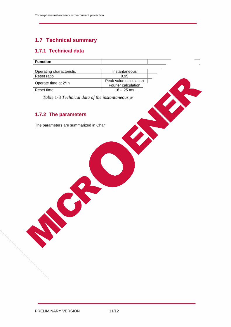
1.7 Technical summary
1.7.1 Technical data
Function
Operating characteristic Instantaneous <2%
Reset ratio 0.95
Operate time at 2*In Peak value calculation
Fourier calculation <15 ms <25 ms
Reset time 16 – 25 ms
Table 1-8 Technical data of the instantaneous overcurrent protection function
1.7.2 The parameters
The parameters are summarized in Chapter 1.5.
Three-phase instantaneous overcurrent protection
PRELIMINARY VERSION 12/12
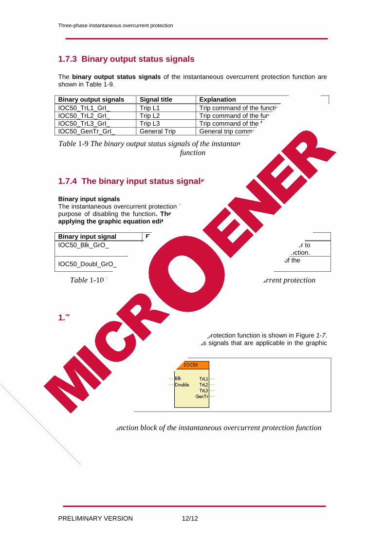
1.7.3 Binary output status signals
The binary output status signals of the instantaneous overcurrent protection function are shown in Table 1-9.
Binary output signals Signal title Explanation
IOC50_TrL1_GrI_ Trip L1 Trip command of the function in phase L1
IOC50_TrL2_GrI_ Trip L2 Trip command of the function in phase L2
IOC50_TrL3_GrI_ Trip L3 Trip command of the function in phase L3
IOC50_GenTr_GrI_ General Trip General trip command of the function
Table 1-9 The binary output status signals of the instantaneous overcurrent protection
function
1.7.4 The binary input status signals
Binary input signals The instantaneous overcurrent protection function has a binary input signal, which serves the purpose of disabling the function. The conditions of disabling are defined by the user, applying the graphic equation editor.
Binary input signal Explanation
IOC50_Blk_GrO_
Output status of a graphic equation defined by the user to disable the instantaneous overcurrent protection function.
IOC50_Doubl_GrO_ If this status signal is logic TRUE then the value of the parameter “Start current” is doubled
Table 1-10 The binary input signal of the instantaneous overcurrent protection
function
1.7.5 The function block The function block of the instantaneous overcurrent protection function is shown in Figure 1-7. This block shows all binary input and output status signals that are applicable in the graphic equation editor.
Figure 1-7 The function block of the instantaneous overcurrent protection function