improving the utility ofa binocular hmd in a faceted ... · binocular head mounted display (hmd) in...
TRANSCRIPT
lnterservice/lndustly Training, Simulation, and Education Conference (l/ITSEC) 2009
Improving the Utility of a Binocular HMD in a Faceted Flight Simulator
Michael P. Browne
SA Photonics
San Francisco, CA
Kirk Moffitt
Human Factors Consultant
La Qninta, CA
kirkmoffittiu)earthlink.net
ABSTRACT
Marc Winterbottom
Air Force Research Laboratory
Mesa, AZ
Marc. 'V,'! interbottom@,mesa.afmc.af.mil
Faceted simulator displays are widely used because they are relatively compact and economicaL One drawback,however, is that viewing distance changes depending on where users are looking. This variation creates a challengefor the integration of binocular head mounted displays (HMDs), because confusing imagery and visual fatigue canresult when the user views symbology presented by the HJ'v1D at one distance and simulator imagery at differentdistances. Understanding the best approach to presenting symbology with a binocular fllv1D in a faceted simulatorhas hecome an important issue, with the deployment of the F-35 Joint Strike Fighter and its hinocular HMD.Successful integration of a binocular HMD would not only allow current faceted simulators to be retrofit with the F35 simulator HMD, hut would also allow future simulators to have either a dome or faceted design, thus affordingacquisition agencies greater 'flexibility. Binocular HI'v1Ds are becoming more prevalent, so solving this integrationissue will likely become impOltant for multiple platforms.
We performed an experiment to quantify tbe best method of presenting symbology on a binocular HMD when usedwith a faceted simulator display. Five viewing conditions were tested: 1) HMD converged to 36", 2) HMDconverged to 42", 3) dynamic HMD vergence, 4) monocular presentation on the HMD, and 5) on-screenpresentation. Screen distances ranging from 36l' to 54" were tested.
Our results. suggest that adaptive vergence is the preferred solution. Both static vergence conditions and themonocular condition resulted in lower comfort scores and poorer performance. The on-screen conditionl althoughrated comfortable, does not represent the real-world flight condition where symbology is displayed using an HMD.Although additional evaluations under more operational conditions remain to be completed, these results indicatethat adaptive vergence is a viable solution for the integration of binocular 1:IJ\1Ds into faceted flight simulatordisplays.
ABOUT THE AUTHORS
Michael Browne is the Vice President of Product Development at SA Photonics in San Francisco, California. Hehas a Ph,D. in Optical Engineering from the University of Arizonals Optical Sciences Center. Mike has beeninvolved in the design, test and measurement of head mounted display systems since 1991. At Kaiser Electronics,Mike led tbe design of numerous head mounted display and rear-projection display systems, including those for theF-35 Joint Strike Fighter. Mike leads SA Photonics' efforts in the design and development of person-mountedinformation systems, including head-mounted displays and night vision systems.
Kirk Moffitt is a human factors consultant specializing in real and virtual displays and controls. He holds a Ph.D.in Engineering Psychology, and has 28 years of industry experience. He is the co-editor of the McGraw-Hili textHead Mounted Displays: Designing for the User. His clients have included military, medical, industrial andentertainment companies. Dr. Moffitt has also taught courses in human factors and statistics for the University ofSouthern California, and seminars on fllv1D design for SPIE and other organizations.
Marc Winterbottom is a Research Psychologist at the Air Force Research Laboratory in Mesa, Arizona. Hisresearch focuses on immersive decision environments, intuitive learningl and visual perception, particularly as itrelates to display technologies for simulation and training applications. He received a M.S. degree in HumanFactors Psychology from Wright State University and a B.A. degree in Psychology from Purdue University.
2009 Paper No. 9178 Page 1 of11
Report Documentation Page Form ApprovedOMB No. 0704-0188
Public reporting burden for the collection of information is estimated to average 1 hour per response, including the time for reviewing instructions, searching existing data sources, gathering andmaintaining the data needed, and completing and reviewing the collection of information. Send comments regarding this burden estimate or any other aspect of this collection of information,including suggestions for reducing this burden, to Washington Headquarters Services, Directorate for Information Operations and Reports, 1215 Jefferson Davis Highway, Suite 1204, ArlingtonVA 22202-4302. Respondents should be aware that notwithstanding any other provision of law, no person shall be subject to a penalty for failing to comply with a collection of information if itdoes not display a currently valid OMB control number.
1. REPORT DATE 2009 2. REPORT TYPE
3. DATES COVERED 00-00-2009 to 00-00-2009
4. TITLE AND SUBTITLE Improving the Utility of a Binocular HMD in a Faceted Flight Simulator
5a. CONTRACT NUMBER
5b. GRANT NUMBER
5c. PROGRAM ELEMENT NUMBER
6. AUTHOR(S) 5d. PROJECT NUMBER
5e. TASK NUMBER
5f. WORK UNIT NUMBER
7. PERFORMING ORGANIZATION NAME(S) AND ADDRESS(ES) SA Photonics,San Francisco,CA
8. PERFORMING ORGANIZATIONREPORT NUMBER
9. SPONSORING/MONITORING AGENCY NAME(S) AND ADDRESS(ES) 10. SPONSOR/MONITOR’S ACRONYM(S)
11. SPONSOR/MONITOR’S REPORT NUMBER(S)
12. DISTRIBUTION/AVAILABILITY STATEMENT Approved for public release; distribution unlimited
13. SUPPLEMENTARY NOTES Interservice/Industry Training, Simulation, and Education Conference (I/ITSEC) held in Orlando, FL on30 Nov - 3 Dec, 2009.
14. ABSTRACT
15. SUBJECT TERMS
16. SECURITY CLASSIFICATION OF: 17. LIMITATION OF ABSTRACT Same as
Report (SAR)
18. NUMBEROF PAGES
11
19a. NAME OFRESPONSIBLE PERSON
a. REPORT unclassified
b. ABSTRACT unclassified
c. THIS PAGE unclassified
Standard Form 298 (Rev. 8-98) Prescribed by ANSI Std Z39-18

Interservice/lndustry Training, Simulation, and Education Conference (I/ITSEC) 2009
Improving the Utility of a Binocular HMD in a Faceted Flight Simulator
Michael P. Browne
SA Photonics
San Francisco, CA
m.brownera>saphotonics,com
Kirk Moffitt
Human Factors Consultant
La Quinta, CA
kirkmoffitt(akarthlink,net
Marc Winterbottom
Air Force Research Laboratory
Mesa, AZ
Marc.Winterbottom(a)mesa.afmc.af.mil
INTRODUCTION
Our previous work (Browne, Moffitt, & Winterbottom2008) investigated visual anomalies while using abinocular head mounted display (HMD) in a facetedflight simulator (a simulator with multiple flat "tiles"instead ofa dome). These anomalies included subjectreports of floating l buried or confusing symbology,doubling of symbology or the background imagery,symbology slanted relative to the simulator screen, andgeneral viewing discomfort. Our primary conclusionwas that these visual anomalies could be problematicwhen integrating binocular HMOs into faceted flightsimulators.
The viewing discomfort subjects reported was likelycaused by diplopia - or double imaging. Diplopiaoccurs often in the real world when we look at mUltipleobjects located at different viewing distances. Whendirecting our attention to a given object, wesubconsciously suppress double vision of objects atother distances, Diplopia is problematic when using abinocular HMD in a faceted simulator because thereare some circumstances, such as targeting an enemyaircraft l where the user must view both the out thewindow display (target) and the HMD image (targetingreticle) simultaneously, as shown in Figure},
Vergence angle is a strong depth cue - an object isseen as closer in depth when the eyes are converged(angled inward) and more distant when the eyes arediverged (becoming more parallel). Figure I-leftshows the position of the two eyes when verged for theout tbe window (OTW) image. If the HMDsymbology is in front of the OTW image, as couldoccur in a faceted display, then that image falls on nonmatching locations in the two eyes, creating a doubleimage of the HMO symbology. Alternatively, if tbeuser shifts their vergence to the HMD symbology'sdepth, tben the OTW image will appear doubled(Figure I-right).
2009 Paper No. 9178 Page 2 ofII
Figure I. Graphical Depiction Of Diplopia CausedBy Concentrating On Two Objects At DifferentDistances Simultaneously. Concentrating On TheOTW Scene (Shown To The Left) Causes ADiplopic Image Of The Reticle. Concentrating OnThe Reticle Causes A Diplopic Image Of The OTWScene.
The specific flight simulator display design of interestfor this investigation is the M2DART (Mobile ModularDisplay for Advanced Research and Training), asimulator display system that can be reconfigured anddeployed for a variety of training tasks around theglobe yet still provide panoramic imagery (Wight, Best& Peppler, 1998). The key to this design is the use ofa faceted display and rear projection. These facetsrange in viewing distance from as close as 36 inches toa practical maximum of 54 inches. This range ofviewing distances creates the potential for vergencemismatch central to our investigations,
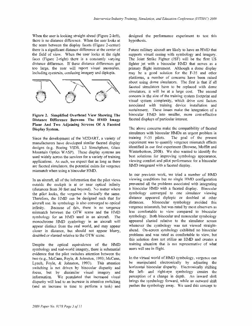
Figure 2 demonstrates a simplified overhead view of afaceted simulator like the M2DART. The green linerepresents the HMO symbology, presented at a fixedvergence distance. Shown also are two OTW displayfacets (one straight abead, one angled on the right). Asthe user looks at different locations within the facetedsimulator, the difference in distance between the HJvlDsymbology (green line) and the display facet changes.
lnterservice/lndustry Training, Simulation, and Education Conference (lllTSEC) 2009
When the user is looking straight ahead (Figure 2-left),there is no distance difference. When the user looks atthe seam between the display facets (Figure 2-center)there is a significant distance difference at the center oftbe field of view. When the user looks at the rightfacet (Figure 2-right) there is a constantly varyingdistance difference. If these distance differences gettoo large, the user will report visual anomalies,including eyestrain, confusing imagery and diplopia.
Figure 2. Simplified Overhead View Showing TheDistance Difference Between The HMD ImagePlane And Two Adjoining Screens Of A FacetedDisplay System.
Since the development of the M2DART, a variety ofmanufacturers have developed similar faceted displaydesigns (e.g. Boeing vms, L3 SimnSphere, GlassMountain Optics WASP). These display systems areused widely across the services for a variety of trainingapplications. As such, we expect that as long as thereare faceted simulators, the potential exists for vergencemismatch when using a binocular IlMD.
In an aircraft, all of the information that the pilot viewsoutside the cockpit is at or near optical infinity(distances from 30 feet and beyond). No matter wherethe pilot looks, the vergence is ba\)ically the same.Therefore, the HMD can be designed such that foraircraft use, its symbology is also converged to opticalinfinity. Because of this, there is no vergencemismatch between the OTW scene and the HMDsymbology for an HMD used in an aircraft. Themonochrome HMD symbology in an aircraft willappear distinct from the real world, and may appearcloser in distance, but should not appear blurry,doubled or slanted relative to the OTW scene.
Despite the optical equivalence of the HMDsymbology and real-world imagery, there is substantialevidence that the pilot switches attention between thetwo (e.g., McCann, Foyle, & Johnston, 1993; McCann,Lynch, Foyle, & Johnston, 1993). This attentionswitching is not driven by binocular disparity andfocus, but by dissimilar visual imagery andinfonnation. We postulated that increased visualdisparity. will lead to an increase in attention switching(and an increase in time to perform a task) and
2009 Paper No. 9178 Page 3 of 11
designed the performance experiment to test thishypothesis.
Future military aircraft are likely to have an HMO thatsupports visual cueing with symbology and imagery.The Joint Strike Fighter (.1SF) will be the first USfighter jet with a binocular IDvID that serves as aprimary flight instrument. Although a dome displaymay be a good solution for the 1'-35 and otherplatfonns, a number of concerns have been raisedabout using dome simulators. The first is that if allfaceted simulators have to be replaced with domesimulators, it will be at a large cost. The secondconcern is the size of the training system footprint andvisual system complexity, which drive cost factorsassociated with training device installation andsustainment. These issues make the integration of abinocular HMO into smaller, more cost-effectivefaceted displays of particular interest.
The above concerns make the compatibility of facetedsimulators with binocular HMDs an urgent problem intraining F-35 pilots. The goal of the presentexperiment was to quantify vergence mismatch effectsidentified in our first experiment (Browne, Moffitt andWinterbottom, 2008). We also wanted to identify thebest solutions for improving symbology appearance,viewing comfort and pilot perfonnance for a binocularHMD integrated with a faceted display.
In our previous work, we tried a number of HMDviewing conditions but no single HMD configurationprevented all the problems associated with integratinga binocular HMD with a faceted display. Binocularsymbology converged to one simulator viewingdistance appeared diplopic or doubled at otherdistances. Monocular symbology avoided thisvergence mismatch, but was rated by most observers asless comfortable to view compared to binocularsymbology. Both binocular and monocular symbologyappeared slanted relative to the simulator screenwhenever the symbology was not viewed straightahead. On-screen symbology exhibited no binocularproblems and was rated as comfortable to view, butthis solution does not utilize an H:MD and creates atraining situation that is not representative of whatusers will see in flight.
In the virtual world of HMD symbology, vergence canbe manipulated electronically by adjusting thehorizontal binocular disparity. Electronically shiftingthe left- and right-eye symhology creates theperception of a change in depth. An inward shiftbrings the symbology forward, while an outward shiftpushes the symbology away. We used this concept to

Interservice/lndustry Training, Simulation, and Education COlr{erence (l/ITSEC) 2009
Figure 3. SimEye SXLSO HMD,
A Souy SXRD 3-panel LCOS (liquid crystal onsilicon) 1920 x 1080 pixel monitor witb a nominalluminance of 35 fL (at the brightest portion of the sky)was used to present the out-the-window (OTW)imagery. The Sony monitor had a horizontal dimensionof 52", as shown in Figure 4. The straight aheadviewing distance was 36" and the nominal viewingposition was 9" in from the left edge of the screen.This allowed us to test viewing distances ranging from36" (straight ahead) to 54" (near the upper right handcomer). These distances encompassed the minimumand maximum viewing distances of the M2DART.
design an adaptive viewing condition thatelectronically and automatically adjusts the vergence ofthe HMD depending on where the user is lookingwithin the faceted display. One of the goals of ourcurrent experiment was to validate this approach bothin tenns of comfort and performance.
METHODS
Observers
Thirteen observers (twelve male and one female), ages25 to 63, participated in our experiments. All hadexperience with the design, marketing or use ofHMDs.Four participants described themselves as "veryfamiliar" with HMDs. Four subjects were fighterpilots, three of whom had extensive experience withthe monocular joint helmet mounted cueing system(JHMCS) HMD. The interpupillary distance (IPD) ofeach subject was measured with an L8 pupilometer,model NH-L8. Eye dominance was determined bynoting which eye was used for sighting through anaperture. Eight participants were right-eye dominantand five were left-eye dominant. Following helmetfitting and HMD adjustment, the resting position ofvergence was measured using nonius targets with adark background. Intact stereo vision was ascertainedby presenting three depth planes of symbols, andasking the subject to identify the close, intermediateand distant figures. Finally, a binocular acuity level of2.6 minutes or 20/52 was verified with on-screen"tumbling Es" presented at the straight-ahead viewingdistance of 36 inches. Six of the participants woreeyeglasses, three of whom had progressive lenses.
52" 'I"
Stimuli aud Apparatus
A Rockwell-Collins Optmnics SimEye SXL50 STMbinocular see-through HMD was used for ourexperiment. This HMD, shown in Figure 3, wasdesigned as a simulator HMD for the F-35 Joint StrikeFighter. It has a 1280 x 1024 pixel format, 40 x 30degree field-of-view (FOY), and monochrome greenimagery. Focus of this unit was 0.9 diopter (notaccounting for chromatic aberration) with a nominaloptical vergence distance of 34.5" (88 cm). This HMDhas a see-through transmission of >70% and was set toa nominal luminance of 6.5 fL. This lfMD clasps ontoan HGU-55/P military flight helmet. Three helmetsizes were available for this study: M, L & XL.
2009 Paper No. 9178 Page 4 of11
(near upperright comer)
Figure 4: Layout of Simulator Screenand Subject Positioning
The trade-off involved with replicating the M2DARTviewing conditions on a single monitor was that ourexperiment presented symbology at a more severeapparent slant angle than found in the M2DART.Some observers commented on this slant but we thinkthat overall the conclusions for our experiment transferto the M2DART.
A PC computer with nYidia GeForce graphics cardsprovided the imagery for both the HMD and monitor.A Polhemus Liberty tracker transmitted head position
lnterservice/lndustry Training, Simulation, and Education Conference (1/ITSECj 2009
and angle relative to the OTW display. Testing tookplace in an area surrounded by black curtains with anominal illuminance of 1.5 fc. HMD luminance,monitor luminance and room illuminance wereperiodically tested to ensure nominal levels weremaintained.
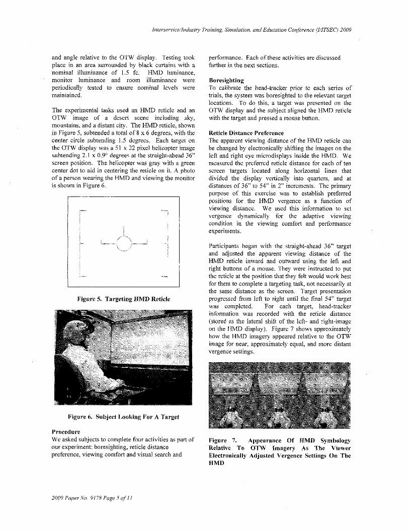
The experimental tasks used an HMD reticle and anOTW image of a desert scene including sky,mountains, and a distant city. The HMD reticle, shownin Figure 5, subtended a total of 8 x 6 degrees, witb thecenter circle subtending 1.5 degrees. Each target onthe OTW display was a 51 x 22 pixel helicopter imagesubtending 2.1 x 0.90 degrees at the straight-ahead 36"screen position. The helicopter was gray with a greencenter dot to aid in centering the reticle on it. A photoof a person wearing the HMD and viewing the monitoris shown in Figure 6.
Figure 5. Targeting HMD Reticle
Figure 6. Subject Looking For A Target
ProcedureWe asked subjects to complete four activities as part ofour experiment: boresighting, reticle distancepreference, viewing comfort and visual search and
2009 Paper Plo. 9178 Page 5 of 11
performance. Each of these activities are discussedfurther in the next sections.
BoresightingTo calibrate the head-tracker prior to each series oftrials, the system was boresighted to the relevant targetlocations. To do this, a target was presented on theOTW display and the subject aligned the HMD reticlewith the target and pressed a mouse button.
Reticle Distance PreferenceThe apparent viewing distance of the HMD reticle canbe changed by electronically shifting the images on theleft and right eye microdisplays inside the HMD. Wemeasured the preferred reticle distance for each of tenscreen targets located along horizontal lines thatdivided the display vertically into quarters, and atdistances of 36" to 54" in 2" increments. The primarypurpose of this exercise was to establish preferredpositions for the HMD vergence as a function ofviewing distance. We used this information to setvergence dynamically for the adaptive viewingcondition in the viewing comfort and petfonnanceexperiments.
Participants began with the straight-ahead 36" targetand adjusted the apparent viewing distance of theHMD reticle inward and outward using the left andright buttons of a mOlise. They were instructed to putthe reticle at the position that they felt would work bestfor them to complete a targeting task, not necessarily atthe same distance as the screen. Target presentationprogressed from left to right until the final 54" targetwas completed. For each target, head-trackerinfonnation was recorded with the reticle distance(stored as the lateral shift of the left- and right-imageon the HMD display). Figure 7 shows approximatelyhow the HMD imagery appeared relative to the OTWimage for near, approximately equal, and more distantvergence settings.
Figure 7. Appearance Of HMD SymbologyRelative To OTW Imagery As The ViewerElectronically Adjusted Vergence Settings On TheHMD

Interservice/lndustry Training, Simulation, and Education Conference (l/ITSEC) 2009
Viewing Comfort RatingWe expanded on our initial work to check viewingcomfort as a function of viewing condition (Browne etal.). We changed the experiment to include bettercontrol over the reticle distance independent of subjectinterpupilliary distance. We also checked viewingcomfort over more distances and included an adaptivecondition along with the fixed binocular, monocularand on screen conditions. For this adaptive condition,we. used the head tracker to indicate where the subjectwas looking and changed the vergence such that thereticle viewing distance was approximately the same asthe distance from the user to the OTW display.
Each trial started with practice targets located at threescreen positions. Subjects were instructed to firstpreview the task by rotating their head to position thereticle over each target to see what different vergencemismatches looked like.
Once the practice session was over, the subjectreturned to the starting position, positioned the reticleover the 36" straight-ahead target and called out arating of viewing comfort: "Not uncomfortable toview", "Somewhat uncomfortable to view" or "Veryuncomfortable to view". This sequence was repeatedfor seven targets located from 36 to 54 inches along thehorizontal mid-line in 3" increments.
The not/somewhat/very uncomfortable ratings wereadapted from similar scales with approximately equalintervals (e.g., Babbitt & Nystrom, 1989). Subjectswere instructed that "Not uncomfortable to view"means that the image may look unusual, but not blurry,doubled or confusing. You could easily view thisimage for a period of time. "Very uncomfortable toview" means the image may be blurry, doubled orconfusing--something you would not want to view forany length of time. "Somewhat uncomfortable toview" describes a viewing comfort between these twoextremes.
Five viewing conditions were tested: 1) Vergence setto the preferred reticle distance for the 36" target, 2)Vergence set to the preferred reticle distance for the42" target, 3) An adaptive distance that adjusted thereticle to the user preferred distance for each target, 4)Monocular, presented in the right-eye, and 5) On~
Screen, where the reticle was drawn on the OTWdisplay.
Visual Search and PerformanceIn this experiment we investigated whether the viewingcondition is simply a comfort and perception issue, or
2009 Paper No. 9178 Page 6 of11
if visual performance was also affected. Palticipantswere asked to search for helicopter targets located atten locations on the screen. These locations ranged indistance from 36" to 54" in 2" increments. Thehelicopter could appear in any of 10 positions, but allpositions were randomly presented three times duringthe course of the experiment. \Vhen a target waslocated, the subject aligned the I-L1\1D reticle with thetarget and the reticle changed to a "missile lock"configuration (four alTOWS sUlTounding the targetingreticle, as shown in Figure 8). After one second ofaccurate alignment (representing a "missile lock"), athree-digit number was displayed on the reticle andanother three-digit number was displayed on-screen,For the on-screen viewing condition, both numberswere displayed on-screen. These spatially adjacentnumbers were compared by the participant. Theparticipant was instructed to push the left mouse buttonif they were the same, and the right button if different.If an error was made, the subject was required to enterthe correct response. After a correct response, a newtarget randomly appeared at one of the remaininglocations, and the subject continued the search task.The numbers were displayed against a darkbackground to ensure consistent contrast across alltarget locations.
Figure 8: Lock Reticle
The five viewing conditions tested in the viewingcomfort experiment were also used for this experiment.The preference data from the first experiment wereused to adjust reticle distance for the adaptivecondition. Three sequential trials were run for eachcondition. We randomized the order of presentation ofeach viewing condition across subjects to minimizelearning and fatigue effects on the aggregate data.
We designed this experiment to replicate conditions ina real simulator environment where operators mustredirect their attention between HMD symbology andon-screen imagery. The primary data from this taskwere total time to find and compare numbers at the ten
lnterservice/lndustry Training, Simulation. and Education Conference (l/lTSEC) 2009
target locations. We also recorded single target timesfrom acquisition to response.
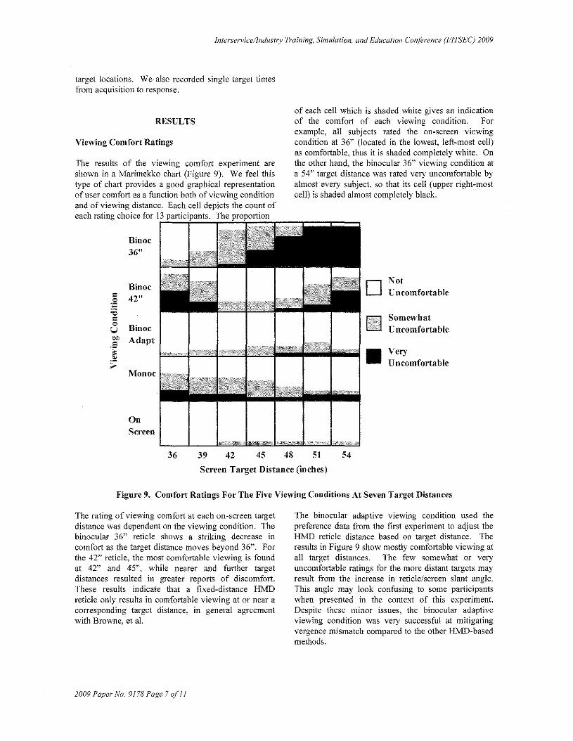
of each cell which is shaded white gives an indicationof the comfort of each viewing condition. Forexample, all subjects rated the on-screen viewingcondition at 36" (located in the lowest, left-most cell)as comfortable, thus it is shaded completely white. Onthe other hand, the binocular 36" viewing condition ata 54" target distance was rated very uncomfortable byalmost every subject, so that its cell (upper right-mostcell) is shaded almost completely hlack.
BinoeNot
:~ 42"LJ ncomfortable
"" Somewhat"0 Binoc UncomfortableUOJ) Adapt.5~ • Very
;; Uncomfortable1\fonoc
Viewing Comfort Ratings
Binoc36 11
RESULTS
The results of the viewing comfort experiment areshown in a Marimekko chart (Figure 9). We feel thistype of chart provides a good graphical representationof user comfort as a function both of viewing conditionand of viewing distance. Each cell depicts the count ofeach rating choice for 13 participants. The proportion
OnScreen
36 39 42 45 48 51 54
Screen Target Distance (incbes)
Figure 9. Comfort Ratings For The Five Viewing Conditions At Seven Target Distances
The rating of viewing comfort at each on-screen targetdistance was dependent on the viewing condition. Thebinocular 36" reticle shows a striking decrease incomfort as the target distance moves beyond 36". Forthe 42" reticle, the most comfortable viewing is foundat 42" and 45", while nearer and further targetdistances resulted in greater reports of discomfort.These results indicate that a fixed-distance HMDreticle only results in comfortable viewing at or near acorresponding target distance, in general agreementwith Browne, et al.
The binocular adaptive viewing condition used thepreference data from the first experiment to adjust theHMD reticle distance based on target distance. Theresults in Figure 9 show mostly comfortable viewing atall target distances. The few somewhat or veryuncomfortable ratings for the more distant targets mayresult from the increase in reticle/screen slant angle.This angle may look confusing to some participantswhen presented in the context of this experiment.Despite these minor issues, the binocular adaptiveviewing condition was very successful at mitigatingvergence mismatch compared to the other HMD-basedmethods.
2009 Paper No.9J78 Page 7of II

Interservicellndustly Training, Simulation, and Education Conference (l/ITSEC) 2009
Results from Browne, et aI, plus our previousexperience with monocular HMDs indicate thatmonocular viewing is problematic, and the data for themonocular condition appear to confinn thisexpectation. The most discomfort was found at thecloser target distances but some subjects even foundthe more distant targets uncomfortable to view with amonocular presentation.
The on-screen reticle was in perfect correspondencewith the screen target and imagery in terms of depth,but it resulted in a high degree of slant relative to theline-of-sight, and it decreased in angular size withdistance. Even so, this viewing condition was rated asmost comfortable to view, in agreement with Browne,et al. (2008).
Visual Search and Performance
We calculated the median search time (time to find thetarget and achieve "lock"), the median response time(time between "lock" and a correct response on thenumber matching task) and the total time (sum ofsearch and response times). The average search timefor all ten targets ranged from 38 to 41 seconds, andthe effect of viewing condition was not significant.Although we measured large differences in the ratingsof comfort for the five viewing conditions, it did nottranslate into a difference in overall performance or insearch time. Both of these metrics include adisproportionate amount of time searching for the nexttarget. The amount of time spent on searching for atarget might be too coarse of a measure to identifydifferences in perfonnance among viewing conditions.
In contrast, response time was directly related to thereticle viewing condition. We defined response time asthe elapsed time between target acquisition and acorrect manual response. We feel that response time isa good metric for proving our hypothesis that thebigger the disparity is between HMD and OTWimagery, the longer it will take the subject to make acorrect response, While differences in backgroundimagery and target location could affect the time tofind each target, the effect on response time should beminimaL
We found significant effects for Viewing Condition[F(4, 48) ~ 3.69, P < .05]; Target Position [F(9,108) ~5.07, P < .001]; and the interaction of ViewingCondition and Target Position [F(36,432) ~ 1.74, P <.0 I].
2009 Paper No. 9178 Page 8 af11
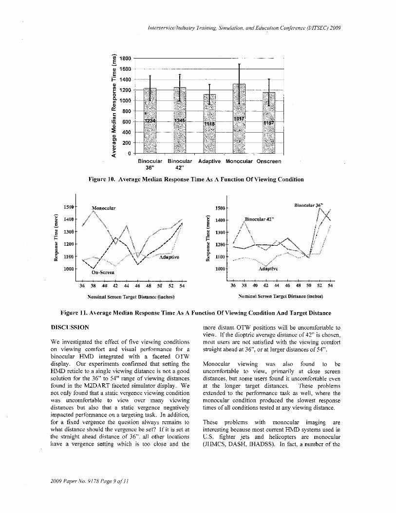
The aggregate median response times across viewingconditions are shown in Figure 10. The adaptiveviewing condition had the quickest aggregate medianresponse time of 1115 msec, Just slightly slower wasthe onscreen condition, with a time of 1157 msec, Thefixed vergence conditions were more than 10% slowerthan the adaptive or onscreen cases and the monocularviewing condition provided the longest response times.
The data show rather large error bars (standarddeviation), representing the significant subject tosubject variation for each viewing condition, but webelieve that the trend is obvious with adaptive andonscreen taking the least time and monocular takingthe most. This indicates that not only are the fixedvergence conditions and the monocular condition lesscomfortable, but they also have an impact on userperformance, at least for a targeting task.
Figure 11 shows how the response time varies a" afunction not only of viewing condition but also oftarget location, We split the viewing conditions intotwo graphs so that the data is easier to visualize. Theadaptive data appears on both graphs. Since it was themost likely condition to be implemented in a realsystem, we wanted to ensure that we could compare allother viewing conditions to it
There is a large variation in response time acrossviewing conditions for the very near targets, withrelatively rapid responses for some viewing conditions(on-screen and adaptive) and others (binocular 36" and42") with significantly slower response times, In themid-distances, there were differences between theviewing conditions, but no obvious trends. At the fardistances perfonnance for all viewing conditionsworsened, while corresponding ratings of "somewhat"and "very uncomfortable" were only found withbinocular 36" and 42" conditions, We attribute thisincreased response time at the longest target distancesto the fact that the font size and contrast were reducedwhen viewed from these distances, Numerous subjectsstated that the numbers were very hard to read at thelonger target distances. We tried to balance theexperiment by not making the numbers too easy to readat the short distances so that there would be thepotential for a noticeable difference between differentviewing conditions. We may need to increase thereadability of the compared numbers for futureexperiments.
lnterservice!lndustry Training, Simulation, and Education Conference (l/lTS'EC) 2009
~ 1800 F.§ 1600 ~~..
I- 1400 +,~+~~~-1
"~ 1200 --rr-I---f""'1I---+---
~ 1000 1."0:: 800~
"'g 600
:l; 400 1·+ 1 I I --I- j_._--"'"f! 200
~«Binocular Binocular Adaptive Monocular Onscreen
36" 42"
Figure 10. Average Median Response Time As A Function Of Viewing Condition
1506
"" 1460~
!~ 13005f=~ 1200ccCo~ 11000:
1000
1500
'" 1406 4BiutlCular 42'l~.s n, \
" 1300, ,
5, \
f ,i: , \
~ 1200 ! " .......C " ......... /,<1
Eo~ 11000:
1000
Binocular 36"
36 38 40 42 44 46 48 50 $2 54
Nominal Screen TargctDlstancc (inches) Nominal Screen Target Distance (inches)
Figure 11. Average Median Response Time As A Function Of Viewing Condition And Target Distance
DISCUSSION
We investigated the effect of five viewing conditionson viewing comfort and visual performance for abinocular HMD integrated with a faceted OTWdisplay. Our experiments confirmed that setting theHl\1D reticle to a single viewing distance is not a goodsolution for the 36" to 54" range of viewing distancesfound in the M2DART faceted simulator display. Wenot only found that a static vergence viewing conditionwas uncomfortable to view over many viewingdistances but also that a static vergence negativelyimpacted perfonnance on a targeting task. In addition,for a fixed vergence the question always remains towhat distance should the vergence be set? If it is set atthe straight ahead distance of 36", all other locationshave a vergence setting which is too close and the
2009 Paper No. 9178 Page 9 of 11
more distant OT\\! positions will be uncomfortable toview. If the dioptric average distance of 42" is chosen,most users are not satisfied with the viewing comfortstraight ahead at 36", or at larger distances of 54".
Monocular viewing was also found to beuncomfortable to view, primarily at close screendistances, but some users found it uncomfortable evenat the longer target distances. These problemsextended to the perfonnance task as well, where themonocular condition produced the slowest responsetimes of all conditions tested at any viewing distance.
These problems with monocular imaging areinteresting because most current HI\1D systems used inU.S. fighter jets and helicopters are monocular(JHMCS, DASH, lHADSS). In fact, a number of the
lnterservice/lndustry Training, Simulation, and Education Conference (l/ITSEC) 2009
subjects who were pilots and had flown JHMCSexpressed concem about the comfort of monocularHNID imagery once they experienced binocular HMDimagery. Whether or not this monocular· discomfortand reduction in perfonnance can be solved withtraining is beyond the scope of this experiment, but itsuggests future research into the efficacy of monocularimaging for both simulation and :flight hardware.
The adaptive condition was more comfortable to viewcompared to any of the other viewing conditions withthe exception of on-screen. This condition alsoshowed the best visual perfonnance in the search task,providing the shortest response times of any viewingcondition tested.
The on-screen condition was the most comfortable toview and resulted in good response time performance,second only to the adaptive condition. There are anumber of issues; however, with using on-screensymbology to train pilots, including the fact that theon-screen symbology follows the slant of the simulatorscreen and does not look geometrically correct. Thiswas especially true at the farthest distance of 54". Inaddition, using on-screen symbology will havesignificant visual differences to users compared tousing symbology presented by an HMD. Since theHMD is a primary flight instrument for the F-35aircraft, we believe that it would be much better totrain users with imagery in the simulator that looks as itwill in flight.
One additional concem is that although vergence ischanged dynamically with the adaptive viewingcondition. we do not change the focus of the HMD asthe user looks at different OTW distances. Normally,focus and vergence are coupled, so objects at the samedepth will appear in focus, and objects at a differentdepth could appear blurred. Although dynamicvergence would manipulate vergence independently offocus, which can potentially be problematic for largediscrepancies (Hoffman, Girshick, Akeley, & Banks,2008), we believe the small distances we are concernedwith will be within a comfortable range and within thedepth of focus of the eye (Winterbottom, Patterson,Pierce, Covas, & Winner, 2007).
Winterbottom, et al showed that depth of focus was notlikely to be an issue provided the difference in depthbetween two images was within a reasonable dioptricrange, as it is for our experiment and in the M2DART.Hoffman, et al (2007) showed that decoupling ofvergence and accommodation can potentially creatediscomfort (at a 0.67 diopter (D) separation). Themaximum separation of 0.18 D used in our experiment
2009 Paper No. 9178 Page J() ofII
and in the M2DART was mnch less than the 0.67 Dtested by Hoffman, et al and thus unlikely to causediscomfort. The maximum distance difference in theM2DART represents a worst case. Other facetedsimulators, with smaller facets, would require dynamicvergence adjustments of even less than the 0.18 Drange that we tested over.
in summary, we believe that adaptive vergenceprovides a viable solution for integrating a binocularHMD with faceted display systems. Thisrecommendation is suppOlted not only by viewingcomfort data, but also by user perfonnance data. Webelieve these results apply not only to the M2DART,but also to other faceted simulator displays with similarviewing distance ranges.
We will seek to confirm our conclusions by integratingthe F-35 simulator IDviD with dynamic vergencecontrol into a state-of-the-art faceted display systemwith pilots executing realistic training tasks under moreoperational conditions.
Development of an adaptive vergence control systemwould provide existing users of faceted displaysystems with a solution for integrating binocularHMDs for future training applications, and provideacquisition agencies with additional alternatives whenevaluating competing display system designs fortraining systems requiring binocular HMDs msimulators.
ACKNOWLEDGEMENTS
The research reported here was made possible viaSmall Business Innovative Research (SBIR) Phase IIcontract FA8650-08-C-6844 sponsored by the AirForce Research Laboratory. In addition, weacknowledge the assistance of Casey Wimsatt inperfonning the software coding, database design,hardware interfacing and for providing valuable inputinto the construction of the experiment. We thank Mr.John Sepanski and the Air Combat Command for theircontinuing support of this project.
REFERENCES
Babbitt, B. A., & Nystrom, C. O. (1989).Questionnaire construction manual (ResearchProduct 89-20). Fort Hood TX: U.S. Army ResearchInstitute for the Behavioral and Social Sciences.

Interservice/lndustry Training, Simulation, and Education Conference (I/ITSEC) 2009
Browne, M. P., Moffitt, K.,. & Winterbottom, M(2008). Vergence mismatch effects in a binocularsee-through HMD. The Interservice Training,Simulation & Education Conference (IIITSEC).Orlando FL.
Hoffman, D., Girshick, A., Akeley, K., and Banks, M.(2008). Vergence-accommodation conflicts hindervisual perfonnance and cause visual fatigue. Journalof Vision, pp. 1-30.
McCann, R.S., Foyle, D.C. and Johnston, .i.e. (1993).Attentionallimitations with head-up displays. In R.S.Jensen (Ed.), Proceedings of the SeventhInternational Symposium on Aviation Psychology,70-75. Columbus: Ohio State University.
2009 Paper No. 9178 Page II alII
McCann, R.S., Lynch, J., Foyle, D.C. and Johnston,J.c. (1993). Modeling attentional effects with headup displays. Proceedings of the Human Factors andErgonomics Society 37th Meeting (pp. 1345 1349). Santa Monica CA: Human Factors andErgonomics Society.
Wight, D. R., Best, L. G., & Peppler, P. W.(1998).M2DART: A real-image simulator visualdisplay system (AFRL-HE-AZ-TR-1998-0097).Mesa AZ: Air Force Research Laboratory.
Winterbottom, M., Patterson, R., Pierce, B., Covas, c.,and Winner,.i. (2007). Depth of focus and visualrecognition of imagery presented on simultaneouslyviewed displays: implications for head-mounteddisplays. Human Factors, pp. 907-919.