hierarchical meso–macro structure porous carbon black as electrode materials in li–air battery
TRANSCRIPT

lable at ScienceDirect
Journal of Power Sources 261 (2014) 156e161
Contents lists avai
Journal of Power Sources
journal homepage: www.elsevier .com/locate/ jpowsour
Hierarchical mesoemacro structure porous carbon black as electrodematerials in Lieair battery
Jun Kang a,*, Oi Lun Li c, Nagahiro Saito a,b,c
aGraduate School of Engineering, Nagoya University, Nagoya 464-8603, Japanb Ecotopia Science Research Institute, Nagoya University, Nagoya 464-8603, JapancGreen Mobility Collaborative Research Center, Nagoya University, Nagoya 464-8603, Japan
h i g h l i g h t s
� We report a new class of hierarchical structure porous carbon black.� The carbon black has excellent mesoemacro hierarchical pore structure.� The hierarchical structure could enhance the cell performance of Lieair battery.� This paper reported a novel synthesis method of mesoemacro structure carbon black.
a r t i c l e i n f o
Article history:Received 23 October 2013Received in revised form27 February 2014Accepted 18 March 2014Available online 26 March 2014
Keywords:Solution plasma processPorous carbonHierarchical mesoemacro porous structureLieair battery
* Corresponding author. Tel./fax: þ81 52 789 4699.E-mail addresses: [email protected], junkm
http://dx.doi.org/10.1016/j.jpowsour.2014.03.0720378-7753/� 2014 Elsevier B.V. All rights reserved.
a b s t r a c t
A new class of hierarchical structure porous carbon black, carbon nanoballs (CNBs), was generated bysolution plasma process (SPP) with benzene. The structural characterization revealed that CNBs haveexcellent mesoemacro hierarchical pore structure, with an averaged diameter size of 14.5 nm and a totalpore volume of 1.13 cm3 g�1. The CNBs are aggregated forming inter-connected pore channels in differentdirections on both the meso- and macrometer length scales. The discharge capacity of CNBs reached3600 mAh g�1, which exceeded the capacity of Ketjen Black EC-600JD (a commercial carbon black withhighest cell performance) by 30e40%. The excellent discharge capacity was contributed by the co-existence of high pore volume and mesoemacro hierarchical porous structure. This new class carbonmaterial exhibited higher discharge capacity compared to commercial porous carbon materials, and ispossible to apply as the next generation of electrode materials in lithiumeair (Lieair) battery. Thestructural and electrochemical properties accompanied with the synthesis mechanism of CNBs werediscussed in details.
� 2014 Elsevier B.V. All rights reserved.
1. Introduction
Lithiumeair (Lieair) battery, due to its high energy density, hasa big potential for the application of future electrochemical powersources. It has a theoretical energy density equals to gasoline, andan energy density is 5e10 times greater than that of lithium-ionbattery [1]. In the application of air electrode material in Lieairbattery, porous carbon materials have an important role due totheir remarkable porosity for oxygen diffusion.
Among various types of Lieair battery, non-aqueous systemappears to be the safest accompanying with the highest recharge-ability. During the discharge process, the non-soluble and non-
[email protected] (J. Kang).
conductive discharge by-product, Li oxides, are formed. In theporous air electrode, the pore entrances are easily blocked by thesedischarge products and thus the deeper reaction sites are still voidyet inaccessible. Therefore, its actual discharge capacity often dropsshort compared to its theoretical value.
As the structure of carbon electrode has a great impact on theperformance of Lieair battery, intensive efforts have been devotedto find out the important factors in designing a porous air electrode[2e5]. There are two key factors including pore size, pore volumewhich can affect the discharge capacity. Between them, larger porevolume allows more Li oxides to accommodate during dischargeprocess. On the other hand, the entrance of the pores clogs easily ifthe pore size is too small, and hence the inner pore volume spacecannot be accessed. Based on previous researches, a pore size<10 nmmight be insufficient to sustain oxygen diffusion andmightbe blocked easily during cathode manufacturing despite using low

J. Kang et al. / Journal of Power Sources 261 (2014) 156e161 157
amounts of binder [5e7]. Therefore, the pore size should be opti-mized to prevent clogging and enhance effective diffusion of oxy-gen over the entire pore network, while pore volume should bemaximized to accommodate large amount of discharge by-products.
For this reason, recent studies has been focused on engineeringcarbon material consists of hierarchical pore structure (containingmacropores and mesopores) [8,9]. The mesopores of this structurecan serves for the storage of LieO2 products, and the macroporescan function as “highways” to supply the oxygen into the innerregions of the air electrode during the discharge process. Therefore,it facilitates a continuous oxygen flow into air electrode withoutclogging.
In this article, a simple synthesis method of porous carbonnanoballs (CNBs) was being reported. CNBs were synthesized bysolution plasma process (SPP) as described in our previous work[10]. Meanwhile, Ketjen Black EC-600JD (KB, Lion Corporation,Japan), a type of carbon blacks which has shown the highestdischarge capacity among other commercial carbon materials, wascompared to the results of CNBs. The difference of carbon structureswere determined by the synthesis mechanism and process. In thestructural characterization, it revealed that KB mainly consisted ofmicroemeso network while CNBs exhibited a hierarchical mesoemacro pore structure. The effect of structural network on thedischarge capacity and electrochemical properties were discussedin details. This paper not only reported a novel synthesis method ofmesoemacro structure carbon, but also suggested the hierarchicalstructure enhanced the cell performance of air electrode in Lieairbattery.
2. Experimental procedures
2.1. Solution plasma processing
The plasma discharge was carried out at room temperatureunder atmospheric pressure conditions. A 100 (mL) glass vesselwith a diameter of 5 cm and height of 7 cm was used as a reactorand pure benzene (99.5% Kanto chemical, Japan) was applied as thecarbon precursor. A pair of tungsten electrodes (F1 mm, 99.95%Nilaco, Japan) was connected with a bipolar-DC pulse power supply(Kurita, Japan). Electrodes were insulated by ceramic tube andprotruded length of 1.5 mm from ceramic tube tip to concentrateenergy. The voltage, pulse frequency, pulse width, and electrodedistance were controlled to be 1.6 kV, 15 kHz, 0.5 ms, and 1 mm,respectively. A schematic of experimental apparatus was beingreported in other research paper by the author [10].
2.2. Drying of sample
After plasma discharge, the solution was filtered by glass mi-crofiber filter (1.0 mm) and the residues (carbon) were dried at 70 �Cfor 1 h.
2.3. Heat treatment
Heat treatment was performed inside a tube furnace at 850 �Cwith a 20 min dwell time and under a flowing argon atmosphere.The heating rate and cooling rate were 25 and 7 �C min�1,respectively.
2.4. Characterization of NPs/CNBs
2.4.1. Morphology of CNBsTransmission electron microscope (TEM) observations were
performed on JEM-2500SE at an acceleration voltage of 200 kV.
Scanning electronmicroscope (SEM) imageswere obtained on JSM-6330F (JEOL) at an acceleration voltage of 5 kV.
2.4.2. Structural properties of CNBs and KBThe porous structure, cell performance and electrochemical
properties of CNBs were compared to a type of commercial carbonblack material, Ketjen Black EC-600JD (KB, Lion Corporation, Japan)in details. The BET surface area, total pore volume, and porediameter were calculated from N2 adsorptionedesorption iso-therms using the BrunauereEmmetteTeller method which carriedout on Belsorp-mini II. All samples were degassed at 200 �C for 2 hprior to the measurement of BET.
2.4.3. Electrical resistivityThe four-point probe method was applied to conduct the elec-
trical resistivity test. Specimens were prepared bymixing 60 wt% ofeach carbon material with 40 wt% of polymer binder (PVDF, poly-vinylidene fluoride, averageMw 534,000, Aldrich, Japan) by mortarand pestle for 10 min. After mixing, the powders were placed into around die of inner diameter 10 mm, and compressed with a force of8 Mpa of pressure at 25 �C for 5 min. The powder was compacted topellets of 2 mm in thickness and 10mm in diameter, and conductedto resistivity experiments.
2.4.4. Preparation of Lieair batteryTo fabricate the air cathode, 0.2 g of carbon material were added
into the mixture of 0.12 g of polyvinylidene fluoride (PVDF, averageMw 534,000, Aldrich, Japan) and 10 g of N-methyl pyrrolydone(NMP, Rikaken, Japan). The circular disks were obtained from thesheets of high-porosity copper foam (1.4 mm thickness, 600 mmaverage pore size) and submerged into the NMP/PVDF/carbonslurry. The copper disc was sonicated for 20 min in order toenhance the slurry penetration into the copper foam structure. Toremove NMP, the cathodes were heated in dryer at 110 �C for 12 h.After drying, approximately 1.5 mg of carbon was loaded on thecopper foam. The electrolyte was 1 M of LiClO4 in an ethylenecarbonate/propylene carbonate (EC/PC ¼ 1:1) solution.
It should be noted that why EC/PC solvent has been chosen aselectrolyte. Although ether- or glyme-based electrolytes are morestable than carbonate-based electrolytes during discharge, it hasbeen reported that they also produce by-products such as Li car-bonate and LiOH, instead of the desired Li2O2 [11e15]. Furthermore,they have a low contact angle on carbon with low O2 solubility andhence tri-phase reaction sites will be reduced [16]. Meanwhile,cyclic carbonate-based electrolytes have a high polarity and theirlow affinity to carbon pores creates tri-phase reaction sites forelectrochemical reaction [16]. By comparing different characteris-tics of electrolytes, EC/PC solvent was chosen in this experimentbecause we would like to solely evaluate the effect of cathodematerial’s architecture on the electrochemical reaction (notrechargeability).
Lithium metal and glass microfiber filter (1.0 mm, Whatman,Japan) were used as the anode and separator, respectively. Type2032 coin cell kits (Miclab, Japan) were used to fabricate cell de-vices and the cap of coin cells were drilled with 20B1mm pinholesto allow oxygen diffusion into the electrode. The Lieair cell wasassembled in an argon-filled glove box. Before discharging, the air-cathode was soaked in electrolyte for 5 min in order to induce agood permeation of the electrolyte into the carbon materials. Cellswere discharged in testing box which has a gas inlet and outlet. Toavoid the negative effect of CO2 andmoisture, dry air (nitrogen 79%,oxygen 21%, humidity < 1%) flow through the box. The humidityinside testing box was less than 1% relative humidity measured by aBK Precision handheld humidity/temperature meter. The operationtemperature and pressure were 25 �C and 1atm, respectively.

J. Kang et al. / Journal of Power Sources 261 (2014) 156e161158
3. A hypothesis of synthesis mechanism and structurenetwork in CNBs and KB
The hypothesis for the mechanism of CNBs by SPP is illustratedin Fig. 1. The porous properties were governed by the carbon par-ticle aggregates. These aggregates can be understood by using thediffusion limited aggregation (D.L.A) model [17]. When carbonparticles were generated in large amount directly from solutionplasma, and these particles simultaneously undergone a randomwalk due to Brownian motion and these particles were combinedtogether in different directions by collisions of individual particles.Carbon black (e.g. KB) in general, is generated from conventionalplasma or combustion method has plentiful sprig, since a largenumber of particles were formed at once and the duration plasma(combustion) zone was relatively long. Thus, the particles weremore likely to aggregate together and resulted in higher structureas shown in Fig.1. In the case of SPP, the plasma zonewas very smalland the aggregates were quickly disturbed by the solution flux. Inaddition, the void volume between the particles of the aggregates(intra aggregate voids) and between aggregates was filled withliquid as soon as aggregates exited the plasma zone. Therefore, thestructures of aggregates became simple as low structure becausethere was not enough time to grow. Thus, the majority of porestructure in CNBs and KBs was significantly different.
4. Results and discussions
4.1. Morphology of CNBs
On average, 500 mg of CNBs were generated from 100 ml ofbenzene with 20 min of SPP process. The morphology of the CNBswas observed under SEM and TEM, as shown in Fig. 2. These imagesrevealed that the diameters of CNBs were ranged from 20 to 30 nmand these carbon spheres appeared as chain-like morphology withrelatively regular size distribution. These particles aggregatedforming inter-connected pore channels in different directions onboth the meso- and macrometer length scales. In other words, theprimary carbon particles arrange into agglomerates. Within theseagglomerates, mesopores of 2e50 nm diameter exist. Agglomerates
Fig. 1. Structure growth of carbon black: (a) carbonization / (b) aggregate / (c) lowstructure (mesoemacropore) / (d) high structure (microemesopore).
coalesce into chainlike aggregates, and a continuous network ofpores is formed in the interstices thus mesopores were well con-nected with the macropores in all directions. Therefore, mesoporesascribed to the void space inside agglomerates, and meso- tomacroporous space inside aggregates of agglomerates. The HRTEMimage shows that CNBs is composed of continuous short graphenelayers, and found to be parallel to the concentric direction withturbostratic structure.
4.2. Comparison of pore structure in CNBs and KB
The pore structure of CNBs and KB were investigated by N2adsorptionedesorption method. Fig. 3a shows the isotherms ofCNBs and KB it exhibited type IV characteristics according to theIUPAC classification and also demonstrated that the adsorptionprocess of CNBs and KB consisted of three stages [18].
The steep initial regionwhere P/P0¼ 0e0.03 indicated the fillingof the micropores; compared to KB, the proportion of micropores inCNBs was very low. In second stage where P/P0 ¼ 0.03e0.86, CNBsillustrated a gradual slope of plateau, representing multilayeradsorption on the external surface. Meanwhile KB showed higheramount of multilayer compared to CNBs due to its high surfacearea. At higher relative pressures where P/P0 ¼ 0.86e0.98, a sharpslope was observed in the isotherm of CNBs and KB with a narrowhysteresis loop. This hysteresis is typically associated with capillarycondensation which predicts the formation of mesoporous struc-tures. Especially, the condensation occurs at higher relative pres-sure indicates the existence of larger pore size distribution. Theseresults illustrated that CNBs possessed mainly mesopores with alarge pore volume to accommodate N2 molecular while KB con-sisted of hierarchical structure containing large portion ofmicropores.
Table 1 presents the detailed structural parameters includingthe BrunauereEmmetteTeller (BET) theory surface area, total porevolume, and mean pore diameter of KB and CNBs. The BET surfacearea and total pore volume of CNBs were 314 m2 g�1 and1.13 cm3 g�1, respectively. The resistivity value of CNBs was com-parable to that of KB. The surface area and total pore volume of KBwere a few times higher than that of the annealed CNBs; however,the mean pore diameter was majorly lower than 10 nm. Accordingto the integral curves of the pore size distribution shown in Fig. 3b,the pore volume in the 2e10 nm diameter range of CNB was notobserved, whereas in the large pore region, i.e., pores >10 nm, adrastic increase in the pore volume is observed. Therefore, it can beassumed that CNB has large pore volume in mesoemacro range. Onthe contrary, KB has large pore volume in the region smaller than50 nm. These characteristics clearly indicated that CNBs consistedof mesoemacropore hierarchical structure while KB consisted ofmicroemesopore hierarchical structure framework.
4.3. Discharge capacity
The voltage-capacity discharge experiments were carried out toevaluate the electrochemical performance of CNBs and KB. Theperformance of Lieair batteries are dependent on several factors,including carbon source, carbon loading, and electrolyte selectionand volume [19e21]. For this reason, the experiments were carriedout under same conditions mentioned in experimental proceduresexcluding carbon source. The discharge profile in Fig. 4 showed thatthe discharge capacity in CNBs reached 3600 mAh g�1 at 0.1 mA.The capacity of CNBs, disregarded of the discharge conditions, wasapproximately 30e40% higher than that of KB. The results implied ahigher pore volume and surface area in KB, as observed in Table 1,did not necessary lead to a higher capacity. This phenomenonagreed with the suggestions of pore blockage of Li oxides by-
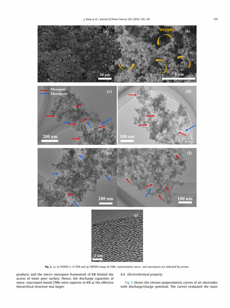
Fig. 2. (aeb) FESEM (cef) TEM and (g) HRTEM image of CNBs, representative meso-, and macropores are indicated by arrows.
J. Kang et al. / Journal of Power Sources 261 (2014) 156e161 159
products and the microemesopore framework of KB limited theaccess of inner pore surface. Hence, the discharge capacities ofmesoemacropore based CNBs were superior to KB as the effectivehierarchical structure was larger.
4.4. Electrochemical property
Fig. 5 shows the chrono-amperometric curves of air electrodeswith discharge/charge potential. The curves evaluated the mass

Fig. 3. Nitrogen adsorptionedesorption isotherms of the CNBs (up) pore size distri-bution curves (down).
Fig. 4. Discharge curves of the Lieair cell.
J. Kang et al. / Journal of Power Sources 261 (2014) 156e161160
transport property of thematerials inside the pores [22,23]. The cellvoltage was stepped down from open circuit voltage (OCV) tobelow 0.6 V because the average discharge voltage of Lieair batteryis usually around 2.5e2.6 V. This curves showed that the dischargecurrent of CNBs was larger than that of KB at the same potentialstep. The results indicated that the hierarchical structure of CNBsmaintained a higher electrochemical reaction and oxygen diffusionrate. These characteristics might be attributed to the effect of poresize. As the size of pore entrance is narrow, a mean collisionalfrequency between materials and carbon in the pathway increases.Thus diffusion resistance also increased and as a result, the masstransport rate to the inner pore decreased. Similar diffusionbehavior was observed in Cottrell plot in Fig. 5(inset). The rela-tionship between diffusion limiting current and diffusion coeffi-cient can be described by the Cottrell Equation (1): [24]
I ¼ nFAC0
ffiffiffiffiffiffiDpt
r(1)
where n is the number of electrons transferred in one electro-chemical reaction step, F is the Faraday constant, A is the electrodearea, D is the diffusion coefficient of oxygen in electrolyte, C0 is theinitial bulk concentration of oxygen in electrolyte and t is the time.The plot of I vs. t�1/2 is linear and the diffusion coefficients D, can be
Table 1Structural parameters/resistivity of annealed CNBs and KB.
Material Surfacearea (m2 g�1)
Pore volume(cm3 g�1)
Mean porediameter (nm)
Resistivity(U m�1)
CNBs 314.0 1.1 14.3 1.6KB 1251.3 2.5 6.5 2.1
obtained from the slope. From Fig. 5 (inset), the diffusion coefficientof CNBs was twice of that of KB. It implied that CNBs has a largediffusion pathway for higher mass transportation rate. The largepore entrance of CNBs might sustain a clear diffusion pathwayduring charging and discharging process because large pathwayenabled high transport rates for both Li ions and oxygen to thereaction sites deep inside the pore.
Fig. 6 shows the impedance spectra of the discharged CNBs andKB at rate of 0.1 mA cm�2 under dry air environment before andafter discharge. A depressed semicircle was observed in high fre-quency region while a straight line appeared at low frequency. Theequivalent-circuit parameters were obtained by curve fitting usingthe Z view software (Solartron)with the equivalent circuit shown inFig. 6. The model impedance spectrum curve showed a good matchwith the experimental impedance spectrum over the entire fre-quency range. The circuit elements can be defined as follows: Rb isbulk resistance of the cell, which includes contributions fromelectric conductivity of the electrolyte, separator, and electrodes[25,26]. Rct and CPE are corresponded to interface resistance relatesto the combination of the faradic charge-transfer resistance [25,27].The linear Warburg element following the semicircle was attrib-uted to the kinetic resistance related materials (Li ions) diffusion[28]. The impedance spectra showed that the Rb of both CNBs andKB were very similar, indicating that the electrodes have equalcombined resistance of the carbon materials, ionic resistance of theelectrolyte, and contact resistance between the material and thecurrent collector. On the other hand, charge transfer resistance ofCNBs increased more significantly compared to that of KB afterdischarging process. During discharge, the non-conductivity Lioxide by-products deposited on the surface of carbon and reduced
Fig. 5. Chronoamperometry curve, Cottrell plot (inset).

Fig. 6. Impedance spectra of the Lieair cell.
J. Kang et al. / Journal of Power Sources 261 (2014) 156e161 161
the electronic conductivity of the cathode, which also led to theincrease of the interfacial resistance between electrode and elec-trolyte. Therefore, if the amount of Li oxide deposited on surface ofcarbon increased, Rct increased accordingly. This result also agreedwith the result of the discharge capacity in Fig. 4.
Meanwhile, the equivalent-circuit parameter showed that thepure capacitors component was replaced by CPE, which associatedwith the degree of non-ideality and resulted in depressing spectra[29e34]. High content (40 wt%) of binder (PVDF) in electrodemightdisturb the ion mobility or adsorption on active site over the entirefrequency range and thusmight affect the ideal capacitive behavior.Generally, double layer which exists at the interface between anelectrode and its surrounding electrolyte does not often behaveexactly as an ideal capacitor, due to the fact that charges on theelectrolyte side of the capacitor are distributed in diffuse layer bydistribution of active sites on the combination of carbon and PVDFsurface.
The impedance spectra at low frequency showed that theimaginary part of the impedance of CNBs was larger than that of KBat same frequency. The behavior might be explained by the differ-ence of pore diameter in carbon materials. With decreasing fre-quency, the electrolyte ions began to penetrate deeper into theporous, then larger electrode surface area became available for ionadsorption, resulting in an increment in imaginary part of theimpedance. However, in the case of KB, it has large portion of mi-cropores and hence the diffusion of Li ion can be interrupted bysmall orifices, thus led to a lower contribution to imaginary part atsame frequency.
In terms of electrochemical performance, the microemesoporestructure in KB might be easily clogged and restrict the accessibilityof the inner pores. In contradiction, the mesoemacropore in CNBsensured higher diffusion rate for Li oxide accommodation andavoided pore blockage. As a result, the effective pore structure forthe Lieair reaction in CNBs was larger and exhibited a higherdischarge capacity compared to KB.
5. Conclusions
500 mg of spherical carbon nano particles, named carbonnanoballs (CNBs), were synthesized successfully by the solutionplasma process (SPP) from 100 ml benzene solution within 20 min.In the hypothesis of the synthesis process, it was assumed that the
plasma zone was very small and the aggregations built by the re-action zone were quickly circulated by solution flux. Therefore, thestructures of aggregations became simple (low structure) becausethe growth time was limited. The structure characteristics provedthat the synthesized CNBs have excellent mesoemacro hierarchicalpore structure, with an averaged diameter size of 14.5 nm and atotal pore volume of 1.13 cm3 g�1. The electrical capacity perfor-mance of CNBs reached 3600 mAh g�1, which was approximately30e40% higher than that of Ketjen Black EC-600JD, a commercialcarbon material which demonstrated the highest capacity. It wasproposed that the mesoemacro hierarchical pore structure withhigh pore volume was more effective and encouraged higherelectrochemical reaction and oxygen diffusion. These factors, as aresult, could contribute to a high discharge capacity in CNBs. SPPsynthesis method can provide unique mesopore structure in CNBsand this type of new class carbon, with its high discharge capacity,might bring the application of Lieair battery one step forward.
References
[1] I. Kowalczk, J. Read, M. Salomon, Pure Appl. Chem. 79 (2007) 851e860.[2] J. Xiao, D.H. Wang, W. Xu, D.Y. Wang, R.E. Williford, J. Liu, J.G. Zhang,
J. Electrochem. Soc. 157 (2010) A487eA492.[3] T. Kuboki, T. Okuyama, T. Ohsaki, N. Takami, J. Power Sources 146 (2005) 766e
769.[4] M. Mirzaeian, P.J. Hall, J. Power Sources 195 (2010) 6817e6824.[5] X.H. Yang, P. He, Y.Y. Xia, Electrochem. Commun. 11 (2009) 1127e1130.[6] C. Trana, X.Q. Yang, D. Qua, J. Power Sources 195 (2010) 2057e2063.[7] R. Younesia, N. Singha, S. Urbonaitea, K. Edströma, ECS Trans. 25 (2010) 121e
127.[8] R.E. Williford, J.G. Zhang, J. Power Sources 194 (2009) 1164e1170.[9] J. Xiao, D.H. Mei, X.L. Li, W. Xu, D.Y. Wang, G.L. Graff, W.D. Bennett, Z.M. Nie,
L.V. Saraf, I.A. Aksay, J. Liu, J.G. Zhang, Nano Lett. 11 (2011) 5071e5078.[10] J. Kang, O.L. Li, N. Saito, Carbon 60 (2013) 292e298.[11] B.D. McCloskey, D.S. Bethune, R.M. Shelby, G. Girishkumar, C. Luntz, J. Phys.
Chem. Lett. 2 (2011) 1161e1166.[12] C.O. Laoire, S. Mukerjee, K. Abraham, E. Plichta, M. Hendrickson, J. Phys. Chem.
C 114 (2010) 9178e9186.[13] C.O. Laoire, S. Mukerjee, E.J. Plichta, M.A. Hendrickson, K.M. Abraham,
J. Electrochem. Soc. 158 (2011) A302eA308.[14] S.A. Freunberger, Y.H. Chen, N.E. Drewett, L.J. Hardwick, F. Barde, P.G. Bruce,
Angew. Chem. Int. Ed. 37 (2011) 8609e8613.[15] D. Xu, Z.L. Wang, J.J. Xu, L.L. Zhang, X.B. Zhang, Chem. Commun. 48 (2012)
6948e6950.[16] J. Read, Electrochem. Soc. 10 (2009) A773eA779.[17] T.A. Witten, L.M. Sander, Phys. Rev. Lett. 19 (1981) 1400e1403.[18] J. Rouquerol, D. Avnir, C.W. Fairbridge, D.H. Everett, J.M. Haynes, N. Pernicone,
J.D.F. Ramsay, K.S.W. Sing, K.K. Unger, Pure Appl. Chem. 8 (1994) 1739e1758.[19] S.S. Zhang, D. Foster, J. Read, J. Power Sources 195 (2010) 1235e1240.[20] S.D. Beattie, D.M. Manolescu, S.L. Blair, J. Electrochem. Soc. 156 (2009) A44e
A47.[21] C.K. Park, S.B. Park, S.Y. Lee, H. Lee, H. Jang, W.I. Cho, Bull. Korean Chem. Soc.
31 (2010) 3221e3224.[22] D. Gerteisen, T. Heilmann, C. Ziegler, J. Power Sources 177 (2008) 348e354.[23] H. Weydahl, S. Møller-Holst, G. Hagen, B. Børresen, J. Power Sources 171
(2007) 321e330.[24] A.J. Bard, L.R. Faulkner, Electrochemical Methods Fundamentals and Applica-
tions, Wiley, New York, 2001.[25] J.Y. Song, H.H. Lee, Y.Y. Wang, C.C. Wan, J. Power Sources 111 (2002) 255e267.[26] H. Wang, H. Huang, S.L. Wunderz, J. Electrochem. Soc. 147 (2000) 2853e2861.[27] X. Yang, Y. Xia, Solid State Electrochem. 14 (2010) 109e114.[28] F. Croce, F. Nobili, A. Deptula, W. Lada, R. Tossici, A. D’Epifanio, B. Scrosati,
R. Marassi, Electrochem. Commun. 12 (1999) 605e608.[29] J.R. Macdonald (Ed.), Impedance Spectroscopy, John Wiley & Sons, New York,
1987.[30] W.H. Mulder, J.H. Sluyters, T. Pajkossy, I. Nyikos, J. Electroanal. Chem. 285
(1990) 103e115.[31] C.H. Kim, S.I. Pyun, J.H. Kim, Electrochim. Acta 48 (2003) 3455e3463.[32] C.A. Schiller, W. Strunz, Electrochim. Acta 46 (2001) 3619e3625.[33] J.B. Jorcin, M.E. Orazem, N. Pebere, B. Tribollet, Electrochim. Acta 51 (2006)
1473e1479.[34] K.B. Oldham, Electrochem. Commun. 6 (2004) 210e214.