ha) e~~y3 - nasa report, volume i television broadcast satellite systems prepared by satellite...
TRANSCRIPT

l IELECTRICAL
EN
0 Lrer
I < t tH
Ha)
.I· k- I
Sepr ingced by ~JZ ~
R
UDP:IV21 RBCEIViD %-.. C
' INPUT INCH'*"J
NGINEERING EXPERIRION
AUBURN UNIVERSITYAUBURN, ALABAMA
rc'M'
E~~Y3
0'~s
~ABRN, ALAedBAM.,r,,,~~~~~lT' CN C ~i 0SEO~L
I I
Et
https://ntrs.nasa.gov/search.jsp?R=19720023526 2018-07-15T05:17:18+00:00Z

Final Report, Volume I
Television Broadcast Satellite Systems
Prepared By
Satellite Communications Laboratory
E. R. Graf, Project Leader
Contract NASA-24818 e -/ /George C. Marshall Space Flight Center
National Aeronautics and Space AdministrationHuntsville, Alabama
Approved By: Submitted By:
E. R. GrafProfessorElectrical Engineering
C. C. Carroll.Professor and HeadElectrical Engineering

N O T I C E
THIS DOCUMENT HAS BEEN REPRODUCED FROM THE
BEST COPY FURNISHED US BY THE SPONSORING
AGENCY. ALTHOUGH IT IS RECOGNIZED THAT CER-
TAIN PORTIONS ARE ILLEGIBLE, IT IS BEING RE-
LEASED IN THE INTEREST OF MAKING AVAILABLE
AS MUCH INFORMATION AS POSSIBLE.

FOREWORD
This is Volume I of two volumes, which make up the final report
of a study conducted by the Electrical Engineering Department under the
auspices of the Engineering Experiment Station of Auburn University.
This final report is submitted toward fulfillment of the requirements
prescribed in NASA Contract NAS8-24818.
Problems of system weight and picture quality are discussed for a
satellite television broadcast system in this first volume.
Volume II of the final report discusses coverage and weather atten-
uation in detail.
!Two other technical reports were submitted during the contract
period: Technical Report No. 1, "Receiver Antennas for Application in
a Television Broadcast Relay System," dated 30 January 1970; Technical
Report No. 2, "Television Broadcast Relay System," dated 30 November
1970.
ii

ABSTRACT
Empirical expressions are derived to account for various components
of the Television Satellite Broadcast System. Computer programs are
developed to determine the system weight in any general design. The
factors of picture quality, propagation losses and R. F. power require-
ments are discussed and determined for a particular case.
iii

ACKNOWLEDGEMENT
The authors wish to express their appreciation to the many members
of the group from the Auburn University Electrical Engineering Depart-
ment, both student and faculty, who contributed to the overall pre-
paration of the study.
In addition, we are greatly indebted to Mr. Grady Saunders of NASA
in Huntsville, Alabama, for his valuable assistance throughout the entire
project.
iv

TABLE OF CONTENTS
LIST OF FIGURES . . . . .. . . . . . . . .
LIST OF TABLES . . . ... . . . . .. . .
LIST OF SYMBOLS . . . . . . . . . . . .
I. INTRODUCTION . . . . . . . . . . .
II. ANTENNAS . . . . . . . . . . . . . . .
III. POWER SUPPLY .. . . . . . .
IV. OTHER SYSTEM PARAMETERS . . .
V. TOTAL SYSTEM WEIGHT . .. . . . . . . . .
VI. SATELLITE TRANSMITTER POWER REQUIREMENTS
VII. STATE-OR-THE-ART . . . . . . . . . .
REFERENCES
APPENDIX . . . . . . .
v
. . . . . . . . . . vi
. . . . . . . . . . vii
.......... ix
. . . . . . . . . . 2
. . .. 4. . . . . .. 25
40
. . . . . . . . . . 25
. . . . . . . . . . 32
. . . . . . . . . . 40
. . . . . . . . . . 58
60

LIST OF FIGURES
1. Antenna weight vs frequency for eight antenna weightfactors (1 - 4GHZ) ..... ... .... . .. . . . .. 8
2. Antenna weight vs frequency for eight antenna weightfactors (8 - 12GHZ) ..... . .............. . 9
3. Solar cell weight vs power frequency=l-4 GHZ . ... . . . . . 15
4. Solar cell weight vs power frequency=8-12 GHZ . ... ..... 16
5. Communication system weight vs power frequency-1-4 GHZ .... . 22
6. Communication system weight vs power frequency-8-12 GHZ .... 23
7. Attitude, orbit control and structure weight (1 - 4GHZ) . . .. 28
8. Attitude, orbit control and structure weight (8 - 12GHZ) . . . . 29
9. Total weight vs power (2GHZ) .................. 31
10. RF amplifier weight vs power . . . . . . . . . . . . . .. . 50
11. RF amplifier weight vs power .................. 51
vi

LIST OF TABLES
1. Antenna weight vs frequency for eight antennaweight factors (1 - 4GHZ). . . . . . . .
2. Antenna weight vs frequency for eight antenna weightfactors (8 - 12GHZ) . . . . . . .. . . . . . . . . .
3. State of the art of silicon solar cells . . . . . . .
4. Low weight roll-up solar array developments . . . . .
5. Solar cell array weight vs power for 1-4 GHZ . . . .
6. Solar cell array weight vs power for 8-12 GHZ . . . .
7. Communication system weight vs power (1 - 4GHZ)
8. Communication system weight vs power (8 - 12GHZ)
9. Attitude, orbit control and structure weight(Freq. 1 - 4GHZ)
10. Attitude, orbit control and structure weight(Freq. 8 - 12GHZ) . . . . . . . . . . . . . . . . .
11. Total weight of satellite . . . . . . . . .
12. TASO picture quality grades . . . . . . . . . . . . .
13. FM broadcasting at 2.5 GHz. Transmitter power pervideo-channel . . . . . . . . . . . . .. . . . . . .
14. FM broadcasting at 12 GHz. Transmitter power/videochannel . . . . .. . . . .
15. RF amp parameters vs power . .. . . . . . . .
16. RF amp parameters vs frequency . . . . . . . . .. .
17. RF amp parameters vs gain . . . . . . . . . . . . . .
18. RF amp parameters vs weight
vii
. . . . . . 6
. . . . . . 7
. . . . . . 11
. . . . . . 13
. . . . . . 17
.. . . .. . 18
. . . . . . 20
.. . . . . . 21
. . . . . . 26
27
30
33
. . . . . . 38
. . . . . . 39
. . . . . . 42
. .. . . . 44
. . . . . . 46
48
. . . . . .
. . . . .

19. Solar cells data from the Boeing Company . . . . . . . .
20. Solar cells data from Fairchild Industries . . . . .
21. Solar cell array data from the Boeing Comapny . . . . .
22. Solar cell array data from Fairchild Industries . . . .
23. Nickel cadmium battery specifications from theBoeing Company . . . . ..................
24. Nickel cadmium battery specifications from FairchildIndustries . . . . . . . . . . . . . . . . . . . .
. . . . 52
. . . . 53
* . . . 54
. . . . 55
. . . . 56
. . .. 57
viii

SYMBOLS
W = total system weight (lbs)
WA = antenna system weight (lbs)
WS = solar array system weight (lbs)
WTR = weight of transmitter (lbs)
WpS = weight of electrical power subsystem (lbs)
WTh = weight of thermal control (Ibs)
WT = WTR + WPS + WTh
WAO = weight of attitude and orbit control (lbs)
WAST = weight of antenna, solar array, transmitter, power subsystem andthermal control
WST = weight of structure (lbs)
K1 = antenna weight factor (lbs/sq ft)
K4 = solar cell array weight factor (lbs/kw)
K5 = efficiency of transmitter
K2, K3 = constants that determine the weight of transmitter, powersubsystems and thermal control equipment
K6 = constant that determines weight of attitude, orbit control andstructure
3 x 10¹⁰C = velocity of light 30.48 ft/sec
AS = area of coverage on earth (sq. miles)
S = distance between transmitting and receiving antennas (miles)
ix

f = frequency (Hz)
P = transmitter output power (kw)
x

Television Broadcast Satellite SystemsS. G. Chandra, H. V. Poor, D. G. Burks, E. R. Graf
I. Introduction
The television systems around the world have seen a very rapid growth
in the last few years. The effects of television have been numerous.
Most of the countries have adopted television as a means to achieve
national unity, and mass communication.
The most important problem in any country, is that of ensuing a
good ground coverage of the broadcasting signals so that the percentage
of homes which can receive television without complex aerials or ampli-
fying equipment approaches 100%. At the present time, to achieve close
to 100% coverage with ground links requires a very large number of con-
ventional transmitting stations and the increase in distribution costs
to achieve this coverage would be very much higher than the increased
revenue that would result. The most attractive alternate to this is to
have one ground transmitting station for each channel and beam its output
to a geostationary satellite and for the satellite responder to relay the
signals direct to the home receiver. A geostationary satellite (altitude
about 35870 km above the equator) would permit a continuous broadcast
service to areas as small as individual countries or as large as continents
up to about 1/3 of the earth's surface. A geostationary satellite also
permits the use of a fixed receiving antenna of very high gain.
The development of a Television Broadcast Satellite (TVBS) is now
accepted as technically feasible and economically profitable. Such as
1

2
satellite system includes a large number of subsystems interrelated in a
complex fashion. A number of different system configurations are possible
and for each system, the design involves an examination of the interre-
lations among and the choice of a set of subsystems to optimize in some
sense the resulting system.
The system weight is an important design consideration and an effort
is made in this report to give simplified relationships for the subsystem
weights, considering all possible variables. Also state-of-the art of
the system components, attenuation of the signal and picture quality are
discussed.
II. Antennas
An ideal television broadcast satellite transmitter antenna requires
a minimum RF power to provide the required field strength over the entire
area to be covered. Other aspects affecting the antenna design are side
lobe level, beam pointing accuracy, power handling capability, multiple-
beam capability, deployment and compatibility with satellite weight and
size. Detailed analysis of these factors have been made in various
reports [1,2,3,4].
Most high gain directional spacecraft antennas have been parabolic
reflectors because they are simpler in design and lighter in weight for
a given gain. They may be divided into two categories. Small antennas
which can be launched in operating position and large antennas which
due to shroud limitations must be folded for launch and then deployed in
space.

3
An antenna diameter of approximately 10 ft. divides the two classes.
This means that for all bandwidths at 0.9 GHZ and for bandwidths less
than about 30 at 2.5 GHZ, a deployable reflector is required.
Deployable parabolic antennas may be classified into three groups:
(1) Flexible reflector surfaces
(2) Rigid reflector surfaces
(3) Inflatable structures
Many concepts for deployable antennas have been described in the
literature and a few typical of these are compared in Tables 1, 2, and
3 of Chapter IV in reference [1].
A flexible reflector surface such as metallized film or wire mesh
can be supported by a system of ribs or cables which define and maintain
the required parabolidal shape. For frequencies up to approximately
5 GHZ, antenna surface qualities and deviations from a true parabolid
required to minimize reflector losses are such that a flexible reflector
is preferred. The minimum weight design of such an antenna we found to
be "Elastic Recovery Umbrella", a 6 ft. size model developed by TRW
Systems, with a unit weight of 0.04 lbs/ft2. The maximum weight design
is an umbrella type reflector, 10 ft. model developed for solar concen-
trator by NASA Langley, with a unit weight of 0.312 lbs/ft2, other devel-
opments are with unit weights of 0.1, 0.13, 0.2,and 0.25 lbs/ft2.
A rigid reflector antenna is an assemblage of rigid segments of a
circular paraboloid. These surfaces provide more accuracy, but are
heavier and costly. Models varying from size of 4 ft. diameter to 52 ft.
4
diameter have been developed for frequencies up to 10 GHz. The unit
weight varies from 0.26 to 0.96 lbs/ft2 for these designs.
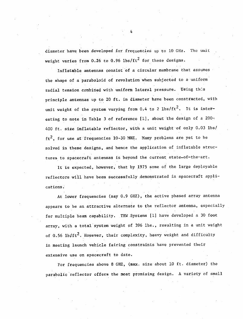
Inflatable antennas consist of a circular membrane that assumes
the shape of a paraboloid of revolution when subjected to a uniform
radial tension combined with uniform lateral pressure. Using thbs
principle antennas up to 20 ft. in diameter have been constructed, with
unit weight of the system varying from 0.4 to 2 lbs/ft2 . It is inter-
esting to note in Table 3 of reference [1], about the design of a 200-
400 ft. size inflatable reflector, with a unit weight of only 0.03 lbs/
ft2 , for use at frequencies 10-30 MHZ. Many problems are yet to be
solved in these designs, and hence the application of inflatable struc-
tures to spacecraft antennas is beyond the current state-of-the-art.
It is expected, however, that by 1975 some of the large deployable
reflectors will have been successfully demonstrated in spacecraft appli-
cations.
At lower frequencies (say 0.9 GHZ), the active phased array antenna
appears to be an attractive alternate to the reflector antenna, especially
for multiple beam capability, TRW Systems [1] have developed a 30 foot
array, with a total system weight of 396 lbs., resulting in a unit weight
of 0.56 lbift2. However, their complexity, heavy weight and difficulty
in meeting launch vehicle fairing constraints have prevented their
extensive use on spacecraft to date.
For frequencies above 8 GHZ, (max. size about 10 ft. diameter) the
parabolic reflector offers the most promising design. A variety of small

5
antennas have been used in space and pose no major technological problems
for the broadcast satellite. The.weight of the antenna system is no more
significant in this case, and the typical system unit weight varies from
about 0.7 to 1.13 lbs/ft2.
The antenna system weight has been computed for all possible types
by using the relation derived in [5].
c2s2
WA = lf2
where WA = Antenna system weight in lbs.
Figure 1 [Table 1].is a.family of Curves of antenna system weight
for the frequency range 1 to 4 GHZ, and for 8 antenna weight factors
ranging from 0.04 to 0.635 lb/ft
Figure 2 [Table 2] is a similar plot for the frequency range 8-12
GHZ and for 8 weight factors ranging from 0.13 to 1.13 lb/ft2 .
III. Power Supply
Reliability, long life and efficiency are the three
be considered in the design of a satellite power system.
vision broadcast satellite must operate for many months,
reliability becomes important. Power supply efficiency,
per pound, is a continuing goal because of the high cost
orbit.
major factors to
Since the tele-
the system's
measured by watts
per pound in
Three sources of energy may be exploited in a spacecraft; nuclear
reactor, radio-isotope thermo-electric generator, and solar cell array.

6
TABLE
ANTENNA WEIGHT VS FREQ FOR EIGHT ANTENNA WEIGHT FACTORS (1 - 4GHZ)
Frequency Antenna Weight Factors (lbs/sq. ft.)
(GHZ) 0.04 0.10 0.13 . 020 0.25 0·.31 0.56 0.635
1.n L ). . 5.7 1 · 77,62 11.9.41. 149. 2o lb5.09 334 35 3 79.13
1. 5 L ..j1 2.5,' 4 5() , 53-.07 66.34- 82.26 148.60 168.50
?.( i7 14 .'3 1i.40 29. 5 ' 37.32 46.27 83.59 94.78
.. 3." 2 .5 12.4 I 2i.4 1.11 23.8 293.61 53.50 60.66
2. 6 6.e3 8.,6 e 13:.271 , 5 2 C .5 7 37. 15 42.13
. ':~ m .4.87 6.34 9..75 12.1 15.11 27.29: 30.95
' .(; 1.4 C 2'.73 4 r8i 7.46. 9. 33 . 1 1.57 20.0 23.70,

7
TABLE 2
ANTENNA WEIGHT VS FREQ FOR EIGHT ANTENNA WEIGHT FACTORS (8 - 12GHZ)
Frequency Antenna Weight Factors (lbs/sq. ft.)
(GHZ) 0.13 0.20 0.25 0.31 0.56 0.635 0.70 1.13
1.21 1. 7 2.33 2.89 5.22 5.92 6.53 10.54
P.5 :I .07 1.65 2.C7 2.56 4.63 5.25 5.78 9.34
C C .96 1.4 7 1 . '4 2.29 4.1 H 4.68 :5.16 8.33
.5 C.86 i.2 L [. 2.0C 5 3. 70 4 .20 4.63 1.48
10.0 C.78 1-.19 1.4Y I1.5 1.34 3 .9 - i . 18 6.75
10.5 C.7C I1.CP 1 .35 1.e£ 3.(C3 3.44 3.79 6.12
11.0 (C.64 u. 9 1..23 1. 53 2.76 3.13 .3.45 5.58
11.5 C 5.'; C cc . 13 14C 2. 3 2.87 3.16 5.10

8
Antenna Weight Factors (lbs/sq. ft.)
A - 0.04O - 0.10A - 0.13+ - 0.20X- 0.25v - 0.31# - 0.56X - 0.635
1- .1, i .l r( C . Li CJ ' . C( (!FI E r(-[{NC Y I N ! r-~
qJNT ENNq; iT I'- FRE(-r', QU NC'
FOR F El T H NT NTEiNNq H!T F'Cq(;T - ' . (1 - 4GHZ)
Figure 1
(~Dc}
C)-
c _ir I
LD
. _ ),C_:i
CD,. I
J
C--IL
- -
L · I. .I .

9
Antenna Weight Factors (lbs/sq. ft.)
0- 0.130- 0.20A- 0.25+- - 0.31X - 0.56
0 - 0.635+ - 0.70X - 1.13
. ! t , 3, 4, 0 {-I .3 tW
FiNTEII Nc, V -j F
- 'UNC F
C'R E'- 'T iNTNNq NT F iT r-;
iI
i ('. C4 I 1
(8 - 12GHZ)
Figure 2
-- ,
.9 -1 0 c? I'
C;
, I.7- j

10
Nuclear reactor systems offer the greatest potential in terms of
gross power capability. A growth potential for this system is projected
up to 300 kw. The main problems associated with these systems are limited
lifetime due to generation of helium in fuel casing, heavy shielding
requirements in conversion equipment and low efficiency.
Isotope thermo-electric generator systems have been well researched
and several low powered systems have been developed and flown. However,
the technology base is.still inadequate for the power range of interest
in the TVBS systems.
The technology of solar cell systems is well in hand, primarily
because of their continued use throughout the space program. In fact
it appears that they offer the best source for an efficient, practical
system for long durations.
Silicon solar cells have been commonly used and the manufacturing
techniques for this material are far enough advanced. Silicon cells of
polarity N-on-P are preferred to P-on-N because they are more radiation
resistant and are readily available. These cells may be obtained in
1 x 2, 2 x 2, 3 x 3 and 2 x 6 cm sizes. However only 2 x 2 cm cells are
mostly considered so far because of their cost advantage. The current
state-of-the-art in silicon solar cells with some projections for 1975
and 1980 are given [2] below in Table 3.

11
State of theTable 3
art of silicon solar cells rl1......... Parameter 1970 ...1975 1980LI
Parameter 1970 .1975 '1980
Size/type 2 x 2 cm 2 x 6 cm 4 x 6 cm
N/P Silicon N/P Silicon N/P Silicon
Power/cell 72.8 mw 225 mw 450 mw
Weight* 48 w/lb 55 w/lb 60 w/lb(21 lb/kw) (18 lb/kw) (16.7 lb/kw)
(* Not including Substrate/Structure)
Cadmium sulfide solar cells have also been found to be the most
promising in the thin film category. They seem to offer several advan-
tages in the areas of cost, storage efficiency and radiation resistance.
The following are their typical characteristics:
Power/cell 157 to 252 mw
Power/area 3.78 to 2.35 w/ft2(40.7 to 25.3 w/m2 )
Power/weight 37 to 75.7 lb/kw(16.7 to 34.3 kg/kw)
However, the disadvantages of these are larger area, low stability
and are not readily available.
Many schemes have been considered for mounting assemblies of solar
cells on a spacecraft. They may be mounted directly on the satellite
body, but the disadvantage is low efficiency and difficulty in maintaining
adequate temperature control, since the spacecraft interior needs to be
kept close to 200 C and the solar cells below 0°C. The weight factor of
such arrays is of the order of 60 lbs/kw.

12
Further as the spacecraft increases in size, the amount of electric
power that can be supplied by surface mounted cells does not increase at
the same rate as the payload volume. To keep power and size in step,
certain deployment schemes have been proposed. The two important methods
of deployment are roll-out and fold-out. The roll-out method differs
from the fold-out scheme only in the manner in which the array/substrate
is packaged. The roll-out winds the array on a drum approximately 10
inches in diameter, similar to a window shade. The fold-out method
"zee" folds the array into a flat pack against the spacecraft body.
The best method from an efficiency standpoint is to mount the cells
on a flat panel which is continuously oriented to face the sun. The
oriented flexible solar array is a highly promising concept for large
spacecraft power requirements (1 to 100 kw) in the 1970's. This fulfills
a critical need for a reliable, low weight, low volume and high power
electric power source.
NASA has concluded many study contracts about the feasibility of
30 watt/lb roll-up solar arrays and the results are encouraging. Typical
characteristics of these and other developments [6,7,8,9] are given
below in Table 4.
A GE study indicates that the utilization of 2 ohm-cm cells results
in a calculated max. power of 2523 watts at 102 volts, where as for 10
ohm-cm cells this results in a max.power of 2294 watts at 90 volts. Based
on this it is concluded that cells with a 2 ohm-cm base resistivity are
required to meet the requirements of 10 watt/sq ft of module area.

13
Low weightTable 4
roll-up solar array developments
Hughes[6] Fairchild Hiller[7] Boeing[8] GE[9]
Type of cell 2 x 2 cm 2 x 2 cm silicon 2 x 2 cm 2 x 2 cmN/P 2 ohm- cell 8 mil thick 8 mil thick 8 mil N/Pcm 7.2 mil 2 ohm-cmthick
Power/cell 49.5 mw
Panel area 88 sq ft 277.4 sq ft 29 sq ft
Number of 34500 61,920 6480 55, 176cells/panel
Power/panel 1500 w 2760 w 290 w 2469 w
Power/weight 21.5 w/lb 34.49 w/lb 20.6 w/lb 32.3 w/lb
Remarks A 500 w model A full scale mechan- Total powerdeployment ical functioning of 1160 wattsand orienta- model has been fab- for 4 panelstion system ricated and has suc- is achieved.has been ver- cessfully demonstra-ified. A ted its ability to1500 w model deploy and retract.under devel-opment in1970.

14
However, TRW Systems [1] select 10 ohm-cm cells over 2 ohm-cm cells,
because of their higher end-of-life performance.
From the above, it may be seen that the weight factor of the solar
cell array varies from about 33 to 60 lbs/kw. Power system weight was
computed for these weight factors and is given with respect to the trans-
mitter output power (P). An efficiency of 65% is assumed for the trans-
mitter in the 1-4 GHZ range and 58% for the 8-12 GHZ range. Futher it is
assumed that the auxiliary power requirement of the spacecraft is 23% of
the transmitter output power. Hence we may write
Ws = K4 ( + 0.23P)K5
where Ws = Solar cell array system weight (lbs)
The computed results are indicated in Figures 3 and 4, and also in
Tables 5 and 6.
IV. Other System Parameters
1. Communications Electronics
The complexity and magnitude of the problems encountered in generating
and transmitting high RF power levels in a space environment have been
discussed in various reports. Useful discussions are made in [10] about
the television broadcast satellite requirements and constraints, and their
impact upon transmitter designs. It is anticipated that future trends
will be toward multiple beam, multiple repeater configurations that
generate sufficient power to allow the use of low-cost terrestrial
D

15
Solar Array Weight Factors (lbs/kwy
ci·1' - 33.0
acn I 0 - An n
A - 50.0+ - 60.0X - 100.0
P(:4 9 TNI\ KWP ~ ~ ~ ~ v ~ ~ ~ ~ F H ~L _ ;k~ V
S( 1 LF- CF LL NE-E CHT V FP-' !L- D
F Er.: i--L ;HZ
Figure 3
crJ
r
_J
.iX -e
(:i
L:. j C,
I i , i L
I'
-1(o

16
Solar Array Weight Factors (lbs/kw)
0 - 33.00 - 40.0A - 50.0+ - 60.0X - 100.0
I I 2 .! " -:r :i; . ,' ! ' pn .t K i,,- I .,
.i.... T ,.: 1 \.i
VF--,R CStL L L ,- T H T V, r-2 , -lC
FR k -1 2 'HZ
Figure 4
c,
2D_
.-
,-
kD -
Ui~r..,
'ZDOJ_
>J I-
('\ .,
EJ
r_
t '
c3
CD
- 1 i

17
TABLE 5
SOLAR CELL ARRAY WEIGHT VS POWER FOR 1-4 GHZ
KW Solar Array Weight Factors (lbs/KW.)
33.0 40.0 50.0 60.0 100.0.~~~~~~ . -- I I -..
2 'j . 1 7? 6
'8I. 3 59 '
8I 7 . -3 R
1]I . 7 184
I 5. * O3 i
* I 1) . 4 3 ,52
/,)0 . -, 144
4 37 .694 1
4 6. 5 32
5 5 2. 232 9
554.4 12
S5 ~ 3 . 59 1 8
3 5 . 36 2
7(:. 7 M'i4
IUCt. C '/6
14 i.4I/f4-
2L2. 2i53
247 .5 846
2 2 , 9 536
.418 3. 3230
353.b6'921
3 ; ( . () (1
, 2 4 · 43 C 7
4 53 . 7 73S
4 495. 1 92
53, 3I; . 5 3' 3
565i.'JC 75
6 C r . 27 -
672.01 54
7 7. 3 4
44.2115
88.4230
1 2.6345
1 7 .ii 61
22 1 ; 75 ,
2 65.26' C
'C9 . 48407
- ;3 . 602 i
397. 9036
442. 1 152
4,6 . 3267
'530. 53 'f!7
574. 749X
6 L8.9 614
'63. 17232
7C70 7. Tbg
75 1. * 59- ?
795. 076
84. 23 'C0
5 1. 053 8
1b. 1C76
15'. 1f15
212.2153
26 . 2690
31..3230
371.3 767
424.43 J7
4 7 /. 4 P4 4
I,3,0. 538 3
5F8 '. 5 92
63 6.646()
742.7537
7 5 . 07 6
9 4 8 . :3 1.i 3
901. 91 5 3
954. 9690
1C; . C22q
lC6 1 . C759
88.4231
176. 8460
6 5 . 2 6'3 ()
'4 2. I 152
530. 383
18 . 9614
707. 3 4 3
795. P074
d84 .2305
72 . 6536
106 1. (76 7
1149.499,
1237.S229
1 326 . 3459
1414.76')90
1 '03. 1 921
1591 .61f,52
1:,8C.0383
1 I7 .t * 6;
0. 5
1. . 5I.C
2.
3.5
7. 0
4.5
5.C
5.5
7. 0
7.5
1.C9.0
LC.,L I I
-r
.L
-r7
J.L-L.

18
TABLE 6
SOLAR CELL ARRAY WEIGHT VS POWER FOR 8-12 GHZ
Power KW Solar Array Weight Factors (lbs/KW)
33.0 1 40.0 1 50.0 1 60.0 100.0
30 .9233
61. : 465
92 7 69 8
1 3 6 93 i
154 .16 3
185. 5396
2 16 .4 61
247. 352
27/8.3 37.
]tj . 2 27
34C. 156I f
371.2 791
4C2 .C024
4 3 2.*257
463.5 49
494.7722
525. e956
6 1 8 7
5 F 7 . 5i 1
6f: 1 .44 4
3 7.428:
714 .9655
1 12. 4482
149 .93 31
187.4 137
224.8965
2 2. 3 792
2 9.6 :I
13 7. 3447
314.82 14
412. 31 C 3
44 . 7930
4 7. 2756
524. 7585
562.2412
599.7241
637.2Ct8
7 4 *.6 892
7 i 1 71 6
74 q . ,5 45
46. 5'34
93. 7068
1 4 C. 5603
187.4 13
234.2612
2 1. 12C6
32 7.9 13-)
374. ,2 14
42 1 .6 C
z43 . 53, 2
51 5. 377
5(62.2412
t1:9 . (C -4 -t
6t 5 .948 o
7C2 .8i0 1
74 . 6'35 5
7 6 5C I
84 3 * jb 1.
F 90 . 1 44
9- 7, c 9 1
- 6. 2241
112.4482
163.6723
224. ')6 5
2;l. 1206
3 3 1. 34: 7
393. 5688
449. 7 (30
5 r 2 2 12
6 1 8 . 4 5 3
674. 6 895
730.9136
787. 1377
4 3. 3 I
,c9. 5862
955. 8103
10C12.337
lC,. *2573
I l 4. i 4s 7
93. 7069 (
I 8 7.4 13 1
2:1. 1204
3 74 . 2 74
468.5342
562.2412
655. "-48
174' 550
8 43 .3. 1I
9)37.C686
I C30.7756
Il124.48327
1218. 16895
I 311 .89,62
1 4 u 5 6 (* , 3 3
1499.9 3103
l193.C171
1lE:6.7231
1780.4290
1.874. 1362
I1.0
1.5
2. C
3.C
3.5
4. i]
4.'
, . S
7. 5
7. 5
c ;
.J5
-, .
,5. '
I-ri
I I . ~ ~ ~~~~~III I
7
iAI ,.1

19
receiving systems. Details with regard to state-of-the-art of the RF
amplifiers is discussed in another chapter.
An approximate weight of the communication system may be determined
by the following relations derived from the curves given in [2]. For
1-4 GHZ range WTR = 28 + 7.5P and fro 8-12 GHZ range, WTR = 23 + 7.8P
where WTR = Weight of the transmitter (lbs).
2. Electrical Power Subsystem
This corresponds to the power conditioning equipment for housekeeping
loads and for power amplifiers, batteries and battery control, power
cables, and slip ring assembly. The weight of each of these components
depend on the transmitter output power. From the relations given in
[1], a simple formula may be approximated to obtain the power subsystem
weight as below:
WpS = 62 + 16.14P
where WpS = Electrical power subsystem weight (lbs).
3. Thermal Control
The temperature of the spacecraft is affected by natural and induced
environment, orientation and internal heat dissipation. Several thermal
control concepts have been investigated. The weight of thermal control
equipment in lbs may be assumed to be about 10 times the transmitter
power in kw.
The weights of transmitter, power subsystem and thermal control
equipment are computed as shown in Tables 7 and 8. The same are plotted
in Figures 5 and 6.

20
TABLE 7
SYStEM WI1GIGH VS POWER (1 - 4GHZ)
P WI R WPS WTH WT
31 . 7500
35. 5CC 0
3g,,5C0
4 3 C C C
46.. 75C0
5C. 5C CO
4 . 25C0
. CC C
C 175C0
e5. 5C CO
6eS 2CO
73 C C o
76. 75C (
E C . SC CO
84 25CO0
E8,CCC
i . 75C
55 . 5CCC
q9.25CO
1C3.CCCO
70 . 0700
7P, 1I4CC
54 ;28C0
1C2 35CO
1 10.42CC
1 18 49 CC
12 6 56C00
134. 63 CO
142.7000C
15 C .77CC
158.84'CC
166.91CC
174 .98CC
1E3.C5C0
191. 12C0
1SS. 19CO
2C7.26CC
6.2500
12.'5C00
i .7500
5.CCC;CU
31.25C0
37.5CCO
43. 750C
5C ;CCOC
56. 2500
62.5C00
68. 75CC
75 .C CCC
81.2500
87. 5C00
93 ;75CC
ICC;. CCC0
C6.25CC
112.5C000
215.33CC 118.7500
223.4CC0 125.CCOC
108.0700
126. 1400
144.21CO
162;.28C00
10EC 35CO
19 .42C0
2 1'6'49CO
234.56C00
252.63CO
27C.7C00O
2 8 .798
306.8398
324. 9099
342.SECO
361.C498
37 911 99
397;. 1F59
41 5.2598
433.3298
451.3599
CU M
0.5
1.0
1.5
2.C
2.5
3.0
?.5
4 .0
4.5
5.0
5.5
6.5
7.0
7.5
.C0
8.5
9 .o
1C .0

21
TABLE 8
C: i':q SYSTEM WtElGHT VS POWE;< (8 - 12GHZ)
| ,, | Wri:' | tPS | W[H W J!T2 6. 9 C 00
3C. 8CCO
34. 7CCO0
3*'.6CC0
42.5C00
46.4CC0
50. 3CCO
54. 2CCO
b5:. ICCO
62.CCC0
6 . ECC 0
'713.7CCO
77. CCO
F i. 5C C0
E8.4CCO
_3. 2CC0
-7.. ICO 0
IC .CCCO
70. 0700
78.14CC
86.21CC
94. 8CC
102. 5C0r
110.42CC
11 8.49CC
126. 5bCC
1 34. (,3C
142. rOCO
150. 77 C0
15P.;4CO
1 6 6.9 10CC
174.98CO
183.05C0
191 . 12C0
1S%. 19CC
2C07. 26C0
215. 333C
2 2 3.40 C 0
*5. 0000
IC.CC00
15. C00CO
20. CCOO
25. CC00
3C .0 C
35. CC 00
4C.CCOC
45.0C 0
5C . CO0
55. CCO0
60 . 0000
65. CC.OC
7C . CCOC
7 ' .COO30
eC. o0000
85.CCO0
90.0()00
9s5.CCOC
1ic). OCo
10 1. 970)
1 18.94 0O
135. )100
1 52,tP 800
169 .85C0
l 6. 8200
203.79C0
220. 7600
237. 1300
254. 70C00
2 7 1. 669
305 . 6099
322.5798
339. 5498
356.5198
373./ 43-)7
390. '46CO
407.4 299
4 24. 3 99
!). 5
I. C
1.5
? .
2.5
3.0
3.5
4.0
i. c
5, r}
5.55 . 5
7 .57 .*
7.5
9 * 5
-) . 5
I C .,~~~~ . IIL-I

22
CDO - WTRO - WPSb - WTH
r:+ - WT .'
_
-y
CJ
H-/
_J
F 1 - GHZ
C. "MM :);STEM St T-,.HT VS F"':z tL
FF(.EC,- 1-L C;HZ
Figure 5

23
.- , C - WTRO - WPS- - WTH+- WT
C_
,? I /
-- J J
A--M-- '3 CHT Vw AE
F .: EUj- 2 GHZ
+~t , -- -~---------~------- , - T t _
P-: -,,^ E r I1 K W
C:iHMY '3 (:3i-E:;l NE i .'HT VSj F-"ON'- ~
F-',E('.S-- '. 2 C!-iz
Figure 6

24
4. Attitude, Orbit Control
The communication satellite, after it is in orbit, is still to be
controlled to derive certain advantages. Two types of control are
required: (1) Control of the location of the satellite in orbit, which
in turn means the control of its orbital velocity, and (2) control of
the attitude of the satellite which means having the capability of main-
taining or adjusting the orientation of the satellite in a precise way
with respect to one or more of three axes.
Various means of control have been discussed and from the information
given in [1] and [11], we may write,
WAO = 0.234 WAST for 1-4 GHZ
WAO = 0.2 WAST for 8-12 GHZ
where WAO = weight of attitude and orbit control WAST =.weight of antenna,
solar array, transmitter, power subsystem and thermal control.
5. Structure
A number of factors influence the size and shape of the satellite.
The desired antenna, housing for the equipment and propulsion system,
the interface with launch vehicle and fairing, type of attitude and
thermal control used, mounting and deployment of solar cells, are the
main factors that determine the type of structure. Hence the structure
weight depends on all of the above factors and from the plot given in
[11] a relation is derived as follows:
WST = 28 + 0.272 WAST for 1-4 GHZ

25
WST = 28 + 0.464 W For 8-12 GHZ
where WST = weight of structure in lbs.
The weights of attitude and orbit control and structure are given
in the following Tables 9 and 10 and also in Figures 7 and 8.
V. Total System Weight
Combining all the previously derived relationships, the total satel-
lite system weight may be obtained by the following relationship:
C2 s2
K4w = 28 + (1 + K6 ) Kl-X m+ K2 + P(K3
- + 0.23K4)
where W = Total system weight in lbs.
A general comupter program is written for the above and is included
in the appendix. A particular system example is choosen as follows to
verify the program.
f = 2.5 GHZ
AS = 1000 miles diameter
K1= 0.2
K4 = 40
The total system weight is computed as a function of transmitter
power and is given in Table II and also in Figure 9.

26
TABLE 9
ATTITUDE, ORBIT CONTROL AND STRUCTURE WEIGHT
(FREQ. 1 - 4GHZ)
4A ST Xa fST WA<S T
0.0n 0~oo ' . 28.C00C 2.CO)
lCCCCC 2.34.CCC 3CC.CCc .534.CC':
2CCC.COC 46P.CCC 572.CCO 1040.000
3CCCvCGC 7/C2.C((O 44.OCO 1546.CCO
4CCC.CCC. 936.CCC 1116.CCO 2052.CCO

27
TABLE 10
ATTITUDE, ORBIT CONTROL AND STRUCTURE WEIGHT
(FREQ. 8 - 12GHZ)
hWASI C. QST. WAOST
0.C C.C - 23.000 28.000
5CC.CCC ICC.CCC 16C.CCC 260.C00
ICCC.CCC 2CC.CCO 2G2.0C3 492.CCO
15CC.CCC 3CC.CCC 424..CCC 724.CCC
2CCC.COC 4CC.;CCC 556.CCC 956.CCC

28
C-I-_,
( I
-- , j
-< * i, ...
Lr!
* i
C ,-L ., -.
, . ~ .~ r ' ,_ AND.
O- WAOA- WST '+- WAOST
. ) _d I
(7-- 1I~ I
C--'*, ICD I
J I
..
U'_. _L-, s
._I
!,- ft i--- i i
f,_, I
C) z .Ir1 C-D i
. i
'TT' TUrtlI, I ,iD L
Figure 7
I
j-,
'- j ', TTI .7 (1 - 4GHZ)

29
CJ.
o-.WAOA - WSTA-- WAOST
I-
i//
I- C /
. . 0\
LT T - ,:D IT C JdTN'(. tND , | or. ( 8 . . .2.
Lr: ~ ~ ~ ~ ~A r ~'0qT:U-" RR'C';
M' b'
~_,c ~ ~~~~~, ~,5_A[ 5 uT:H(-1GZ
Figure 8

TABLE 11
TOTAL WLIC;HT (F SATCLLITE
Xr IT TC PFC aN1LtNNA IN MilL'S
FRECLtkCY IN C-Z
rCIAMEIER F F CCVEHAGE Ik I"ILt::S
CCVcRAGE APFA IN SC MILctS
PChEPR IN vl
ANrTENNa hT FACTCH tN LIS/S.. Fl
ELECTRICAL ANE ELECTRC\IC ECUlPmEfT T WT FACTCR
ELECTRICAL ANC THERmAL CrNTROKIL WT' FACTCR
9CLAtR CELL PRRAY WT FACTCi iNl LCLS/KW
A.t IT IER EFFICIENCY
alTIILCE rCINTPCL ANC SIRLCR TLUR: T FZACC,
TCIAL hEtlrT CF SaTELLITIt
IC TAI Ii- Tl;.I fCh DfIV 1'L:,
7 2CCC. CL CO
2.CCCO
- 1 ~6349..
C C CO= 'OC.CCCO
= 3'6 . 14qo
- 4C.CCCO
:= · C. 5(60
- 1148. 1477
I I L ' 11 JL U ' I V V F: r ILV L
PCWEP I N
PClhQ I N
FCE.ER INPC1~ER II\
FClER tN
KW=
K IA =
K W =
K%,=
KWt=KW=
Fk=
KW=
K k =
h =
I ;')CO0
2 CCCC
3 c CC
4 . C C CC
5.CCCC,
t.CCC
7; CCCC
C;CCtC
IC .. C C Cc
TOTAL WL IGHT=
'ICTa L ,'E C- t-T =
ICTAL WEIGFT=
TCT4L h IGFT=:
T C TA AL F I G F T =TCTAL WEIGd-T-
1C rAL WE [IGT=
TC T iL WIt I GFT=
'C TAL WL I GFT=
IC aL wt EG r=
30
5C4. 3123
C86 5 . 2 2CC
97. g189C
1 4 F . 14 7 7
1 3~C9. 1067
1470. C654
1631. C247
17S 1.9834
1952. $7424s
3

31
CD2::
-LI
LI
-i
--
/,_1
I .'
C._ I
LOuC. -4 L, -*.3
Pli E TI N K !
T@Tr."L WN t.HT V, r'4E' (2GHZ)
r: n~~~~~~~~~~~~~~~~~~~~~~~~~~~~~~~~~~~~~~~~
rlgure 9

VI. SATELLITE TRANSMITTER POWER REQUIREMENTS
1. Picture Quality
The ultimate objectives of any TVBS System is to provide the re-
quired picture quality by the most economical system for the entire
coverage area.
Quality of picture and sound is a subjective concept, since it is
a measure of the degree to which deficiencies in the received signals
are experienced by the viewers. The relation between this subjective
quality and signal deficiency is, of course, an issue of vital importance.
Noise performance requirements on broadcast transmissions have in the
United States been the subject of extensive investigations by the TASO
[12] established by the FCC in the last decade.
In the final report of TASO, the level of television service has
been characterized by specifying the level of picture quality to be
achieved or exceeded. The typical values shown in Table 12 represent
the grade of service for random noise interference.- (Based on 75%
observers)
The numbers (C/N) TASO represent input carrier to noise ratio. Also
they were made in conjunction with an AM-VSB receiver. Since only FM
transmission is to be considered for satellite case, because of the lower
power requirements, the numbers in Table 12 are to be suitably converted
32

33
to determine FM signal level requirements. In this process, the carrier-
noise ratio is first converted into weighted video signal-to-noise-ratio
at the picture tube. TRW Systems [1] have derived analytically equiv-
alent weighted picture-to-noise-ratios for the TASO grades, considering
the effect of camera noise. These are shown as (S/N)wdB in Table 12.
Table 12. TASO Picture Quality Grades
Grade Name (C/N) TASO (S/N)w C/T
1 Excellent 46 49.5 -
2 Fine 38 40.3 -139.6
3 Passable 31 32.2 -141.2
4 Marginal 25 25.9
5 Inferior 19 19.9
Next, considering FM transmission, the required power and band-
width are derived for cases of fine and passable picture quality. These
values are given as (C/T) dBw/OK in Table 12. They correspond to 525
line, color receiver, with a video bandwidth of 4.2 MHz. The required
R. F. bandwidth is found to be 19.8 MHz for fine quality and 13.8 MHz
for passable quality.
-dB dB dBw/uKA n
I - I
j -
I I
.r tO..

34
2. Propagation Medium
Attenuation of the signal results due to a variety of factors in
the propagation medium from satellite to earth.
(a) Free space-loss depends on the frequency and the slant range.
This may be expressed as follows:
LFS = 92.5 + 20log0F
F + 201ogl0 RS
where LFS = Free space loss in dB.
F = Frequency in Hz.
RS
= Slant range in Km.
For synchronous satellite, the slant range is expressed in
terms of a, the zenith angle of the ground antenna [13], as
gS = 44,100 sin[a-sin 1 (0.193sina)]sine
(b) At the frequencies of interest, viz 2.5 GHz and 12 GHz, the
ionospheric effects are of no significance [14].
(c) The effects of atmosphere on the signal are discussed in [15].
They may be summarized by the following equations.
(i) Attenuation due to oxygen and water vapor.
A1 (F) = 1.4 + 0.09x10 9F - 1.6exp(-2.1xlO 9xF)

35
20
A2(r) = 1-exp(-0.00545 in)
A3(0) = exp(-100)
and Ag A(F).A2 (r)'A3(0)
where Ag = total attenuation due to oxygen andwater vapor in dB.
A1 (F) = frequency dependent component of Ag.
A2 (r) = component of Ag dependent on length of ray path
A3(0) = component of Ag dependent on elevation angle
F = frequency in Hz.
a = elevation angle in radians.
(ii) Attenuation due to clouds and fog is given by the follow-
ing:
AC = kpr
where AC = attenuation in dB
k = coefficient in dB/km/gm/m3 .
p = liquid water content (0.3 gm/m3)
r = e (vertical cloud distance is assumed as6km for temperate regions)

36
(iii) Attenuation due to precipitation may be expressed as
follows:
Ap =qpR
where Ap = attenuation due to precipitation in dB.
q = coefficient (assumed lx10-4 for 2.5GHz and3x10-2 for 12GHz)
p = rainfall rate in mm/hr. (assume lOmm/hr)
and R is determined as follows:
Assuming that constant rainfall state of 10mm/hr. over
a hypothetical area, the linear extent of that area may be
obtained as,
E = 41.4 - 23.51og1 0p = 17.9Km.
Further, the height at which the precipitation begins
in temperate zones may be taken as 3km and the length of the
3ray path is then (Bs-n)'
Then R is taken to be the smaller of the two values
(17- ) and (3cose sinO
The total attenuation in the propagation medium is then
the sum of all of the above factors. This is computed for
frequencies 2.5GHz and 12GHz, and for elevation angles of
900, 700, 500, 300, and 100

37
3. Transmitter R. F. Power
The value of satellite transmitter R. F. power
channel at 2.5GHz and at 12GHz is computed as shown
14, for the five elevation angles. The assumptions
putations are:
(1) Fine quality picture (TASO 2) at the edge
area.
required per video
in the Tables 13 and
made in these com-
of earth coverage
(2) Receiver system noise temperature of 800°k for 2.5GHz, for an
adapter with preamplification by one bipolar transistor stage,
and 1300°k for 12GHz assuming the noise figure attainable by
1975 to be 7 dB for a-dual mixer with Schottky-barrier diodes
in the receiver adapter, without R. F. preamplifier.
(3) Half-power beamwidth of 30 for the satellite transmitting
antenna.
(4) Parabolic receiver antenna of 1 meter diameter, at the top
of building.
(5) Uplink noise of 0.3 dB.
(6) Polarization loss of 0.5 dB.
(7) Circuit losses of 1.5 dB.
(8) Satellite antenna on-axis gain of 35 dB.
From the results, it may be seen that at 2.5 GHz, the required
peak transmitter power is of the order of 310 watts/video channel, in
most of the cases. For 12 GHz transmission, this is found to be
about 700-750 watts/video channel.

I~~~~u I~
I
I
£ o ^
e oo
~~~~~~ 's
u)
q)
~~~~~L
\ n
:~~O
C
) ~~~CV
cn) 00
r-4 C
'J U
, '0
,-o0
Lf)-C
m
m4
C
c C
cL
) -
C)
U,
4 v-
C4 -
I -I I
I' s
1 7
I I
.-~
o
'IO
0 CY)
C,, 00
-4. C
) U
,) --,
CD
0 v-I I
-~
+
-v
+
+
I +
0
£ ^.
o *r
~ * a
uz O
oC.
O~
O
~ O
'"l
0 ~
o ~
o.,
* -. ,-1'
I-I I
I I
I -I
aJn
(Y
C 14
m
I L
f C
V)
s uX
<
l
H
~~
~~
~
~ ~~~~~~~~+
+
+
+
bO
~~
~~
~~
~~
~~
~~
~~
~~
~~
~~
~c
00
'IC
CD
M
C
yl C
O
'- C
) U
, C
0 *
* *
* *
U
· ,
co c
I ,it
Cl
M
o'
I u
CY -
ClN 0
0 v-4
t- I-
+
"1 ,
+
+
, +
-I
Cd
CV
)~~~~~C
C
l '
1 0 0
C~ C
') O
v-I
C
c -
, 1
1 1
Cb0
;r
xD
O
n n
qo
~~
~~
~
~ o
·n i.
.y
a 0
.*
..
..U
,. .
OO
00~
0o
) O
O
U
, '.m
O
N
C
O)
U,
Cs
* C
.e
-4~ C
V
C-I
1I v-I
Cl
Cn m
I
, C
_
I C
S O
JJ
v-I I
v-I
+
v-i 1y
+
+
I +
_I
I I
I I
~
tL)~
~~
~~
~~
~~
~~
~~
~~
~~
~~
~~
~~
~~
~~
~~
~~
~Y
-4~
~~
~~
~~
~~
~~
~~
~~
~~
~~
~~
~~
~~
~~
~~
~~
~~
~~
~~
~~
~~
~~
~~
~~
~~
~~
~~
~~
~4
Lr).
0 o C
C
a
-C
o -r
0 0
· C
4O
* *
* *
.0
..
.
Cal
0 0l
0 o)
U,
Z
-O
U
l- I
v-I +
v-
I +
+
*
+
vlIO
O I
I I
I -
0
w ~ ~ ~
~ ~
~ ~
~~
4i ~
~~
~~
~~
~~
~~
~~
~~
~~
~~
~~
~4~
~~
~-
C.4
:3
,1
-. 3
-m
:
1
4-i
-a )
-41
cS o t
t r
.43
X
u
0 (~
oor ~~~~~~~~~~~~~~~~~~H
P4..
.H ~ ~ ~
~ ~
~ ~
~ ~ ~~~
v
a U
~
~4) ,
o-4 .o
-Iii 3 ^
.~~
~ ~~~~~~~~~~~~~~~~~~~~~~~~~~~~~~~~v-
I
00 O
9
I I
p-i *
-'~~
~~
~4
I c*
w O
r. ~
,,4~
- 0
X4
c o0
r 5 4
4- E4
O)
*ri -.
5.
I )
5-
.- I-i
-H
_j
o-
--
-o
c
E~~~~~~~~c >
s -
w
4iX X
~~~~~~~~~~~~~~~~~~~~~~~~~~~~~~~r a)
a 0
v -
0 ·
., ·:4
l0 >
~
3E
v O
' E
~
~ ~~
~ ~
~~
~
~~z rl
>,
cu
OJ
>
U) 4.C
d
0I 0
P 0
0 0
0
v- QX
5 -*'H
a0 0
r H
o
E-4 bJ
44
.0
.v-.
-" 0
'
-a C~
to
*rI *v-
0 C
>
CU
U) U)
I-I
4-J C
4 a)
ct
4-J (1)
c C
a
p '"
"W
4CJ Z
CL
A0
z H
'-' _
0 *
CU CU
C
>
o .
-u
C
*c o
.C
H
H
U
U4. 0)
0 In
*
in. i-H
a)
0 U)
4 )
* X
0J
X'4 C
*
4.. 4)
*- '
q u2
.0
u-i.
D
Co
0 -H
0(ic
4 I t$
a) U)
4i
Q
0. -.
4C
U
a) U
) 0)
0) 1-4
U
>
H
>0
r1 0.
1 0,I
P
P- 0
0 ~
0-- 4..
0 q0
"0
1i a
0i 44
",0 IU
CU
U, 4..
p .
)0
0j ,,1
0v
0 P-v Y
0
*v- 4-
0 0
'4-4I-
eJ 1
3-
t'H
4- -4
*H
4-4 4-i
0 Q
~ ~ ~ ~
~ ~
~ ~
-'o
v-
o *H
Q
-4H
A:
X
-:4 P
4 E-4
4 4 U
P
o
¢
*v *,-
H
'x
>
>
*l
l *J
X
X4
-H
*H
*H
>'-
*,H *,H
,H >-
*H
*H
*H
_ X
H
*r4
Hv
'9
>
'S
~-.XH
38

0 O
.·
· '
O
ay -
o C m
r-
c'i o
r) ei
-i en
o I
e -,..-
I ,.
C-I
I -
+ 1-4
C'4 +
+
I I
I I
Lr) cn
m'O
I Lf)
It V
I
1-4
'.0 ·
-C
e
'i rt
N
u. o
:1 'C
u
.o
.
o a'
, 0
co oN
r- 0
CO 1-4
e -i
0 0
c-inc
cf c
I 0
c -T
0O
I'
\0
%
I C
f4,
'I -l
+ _
I C
+
+ +
,I
I 'I
'
I ,
.
NZ.
i
0
b0 0
*0 a
4.I-
-H
U) >
0 04-
O
OU)
q) p
' -
EH
c00 00
'.0
_I
Lf C
1-.
L-
tU c
-·
r-I I 1
_ +
+
+
v0 D cn
O
*;
· *
.
r- c)n
C') I
n O
I
) c
_I
I, *
1 +
r-I
C14 +
+
r,00-4*
+ L
n
rl ~ r.
I coC
( O
+
-4r-
n m
C
Y)
'0
,4
7 (N
u
) r-
,- I )
L
O
* -
' -4
0o
oo
a'Ci
1-
.o
oo
°
I c0
CY n
I 0
en
-I
o I
uLt) M
C
S
r)
I 4
+ ( C
+ +
+ II
I .0
I
*l * ~
l~
G
M
aC)~~~~~~~~~~.)
·
0
0 (Nj
:-
'o o
'~b
'SO
4 0
~'
' ''
m3~
~ 3
~ *
4.4 .a
)'d h
1
d 0 0
0
ctO
Xl
3 -
U
0
o
I
o
w¢C
e ~~
~~
~~
~~ E
v~
-C4
co-
0 0
* )
..-.
o J
[-
C·1)
M
) .M ~
.M
.M
,.-I .M
,-
=
..
U) O
F'
0 S
* '
*H CO
.
0rX o
co. o
4- 0 O
. *r
E-f -
O
>
v
* ,
..
0 a)
0 a
u h
'H
*H
U )
a u)
0 a4
, Jl
: 4 A
PL
0, 0
) 5
0 *
'· 4-4
Z
0 $J
la
w
C
IV
4-I d
0)
0a) 4-
a) Q
) P-
N
a) *H
4.. 0
0 O
D
Q
' H
0 0
*
: C
C
:
0 0)
V U
-I ~3
U
7 4-i
,-I O
i 4-i
44 >
>
0 0
0 O
0 0
O
0 0
' *H
0
O0
" D
P
H
P
u Q
u
C-)
i, -
·rSl~ ~
S_
.
H
*H
*,1 >
>
*>
*H
'H X
X4
*,1 *.4H
*4
>
_- .4
5-,
' >
H
'
'- X
'H
X
S -,
.r 5 * *
5 *r x
·-o
O
LI
a).~~
39
o0oi--
O
iIII

VII. State-of-the-Art of Components
In order to assess the present and future state-of-the-art of
system components for TVBS, questionnaires were sent to about 75
leading manufacturers of system components for space communications.
The format of the questionnaires are included in the appendix.
Although most of them replied, very few were able to given the type
of information required. After careful study of these, all important
information with regard to the state-of-the-art of R. F. amplifiers,
solar cells, solar arrays, and nickel cadmium batteries is compiled
in the following tables.
Tables 15 and 18 give parameters of space qualified RF amplifiers
that are being manufactured by four firms. In order to arrive at a
relationship between weight and power output of these amplifiers for
different frequency ranges, typical values are plotted in Figures 10
and 11. These reveal that in the extremely low power range from
1 - 10 watt, the Litton TWT's in the 8 - 12 GHZ range have a favorable
power to weight ratio. At power outputs of 20 - 100 watts, Litton
Klystrons operating in the 1 - 4GHZ range present good power to weight
ratios. Good power-to-weight-ratios for all power outputs above 100
watts are obtained with Sperry and Varian TWT's and Klystron's operating
in the 8 - 12GHZ range.
40

41
Tables 19 and 20 indicate the present and future state-of-the-art
of solar cells as furnished by the manufactures. Similarly Tables 21
and 22, give solar cell array data. Finally information about nickel
cadmium battery is given in Tables 23 and 24.

TABLE 15
RF- AMP PARAMETERS VS POWER
POWER FREQ RANGE( W ATTS) (GHZ)
GAIN WEIGHT( DB) (LBS)
COMPANY PART NO
7.0-11.0
8.2-10.0
8.0-14.0
1.0- 2.0
7.0-11.C
E.C-12.C
8.0-14.C
12.4-18.C
5.4-11.0
7.0-11.0
7.0-1 1.0
7.C-12.C
1.C- 2.C
2.0- 4.C
3.7- 6.5
4.0- 8.C
1.7- 2.7
2.3- 2.3
1.0- 2.0
4.0- 8.C
2.0- 4.0
12.4-18.0
2.3- 2.3
7.0-13.C
30.0
60.0
35.0
30.0
36.0
36.0
65.0
35.0
60.0
60.04C.0
30.0
33.0
36.0
33.0
30.0
20.0
30.0
33.0
33.0
33.0
29.0
43.0
1.5
1.5
1.2
0.0
1.5
i,5
1.5
2.0
1.5
2.5
2.5
2.0
3.0
2.5
2.5
2.5
3.5
2.6
3.5
3.5
3.0
7.0
5.0
7.0
LITTON IND
LITTON- IND
LITTON IND
KEL TEC
LITTON
LITTON
LITTCN
LITTON
LITTON
LITrON
L I T TON
LITTON
LI TTCN
LITTON
LI TTON
LI TTON
INC
IND
INC
INC
i N C
IN3
INC
IN-
INC
INC
INr
INOI!NO
.1N' C
SPERRY
LITTON !NO
SPERRY
L-5045
L-3972
L-5339
LR600- 1
L-3998
L-5C08
L-5322
L-5227
L-3957
L-3928
L-5043
L-5293
L-5036
L-50 I
L-5134
L-5011
L-5225
L_3910B
L-5155
L-50P3
L.-5160
STU-54312
L-5044
STX-5225
42
1.
1.
1.
1.
2.
2.
2.
2.
2.
10.
10.
10 .
!0.
I C.
20.
20.
20.
20.
70.
10C.
TWT
TWT
TWT
TWT
TWT
TWT
TWiT
TkT
ThT
TWTT W T
ThT
TkT
rhT
T h T
T h T
KLv
TWT
TWT
K i v
ThT

TABLE 15 (Cont'd)
FREQ RANGE GAIN(GHZ) (DB)
WEIGHT COMPANY(LBS)
14.5-15 .5
7.0-12.0
e 0-14. C
2.6- 5.2
5.C-10.C
7 . 0- 1 1 C
7.4- !1 .C
7.O-I1.Q7.C-11.07 * 0-11 1 C
7.C-13.C
7.0-13.C
2.5- 2.7
2.0- 4.0
8.C-12.0
7.9- 8.4
2.3- 2.3
5.9- 6.4
2.7- 2.E
5.9- 6.4
5.9- 6.4
3.1- 3.5
35.0 7.0
33.0 6.0
40.0 7.0
40.0 lC.0
4C.0 7.0
40.0 8.0
36.0 6.0
40.0 6.0
38.0 7.0
43.0 7.0
4C0.0 7.0
29.0 11.0
40.0 10.0
42.0 12.0
48.0 16.0
3C.C 12.0
46.0 55.0
30C.0 35.0
43.0 22.0
47.1 18.
48.0 120.0
43
SPERRY
SPERRY
SPERRY.
LI I TON IND
LITTON
LITTON
SPERRY
SPERRY
SPERRY
S ' E R R v
SPERRY
LITTON
LITTON
LITTOTCN
VAR I AN
LITTON
VAR I AN
VAR IAN
SPERRY
INC
IND
INO
INC
INC
STU-52271
STX-5224
STX-52270
L-5323
L-5324
L-5280
STX-5220
STX-5222
STX-52260
STX-52251
STX-52261
L5109
L-5281
STX-544CC
VA-914
L-51C1
VA-936C
L3668H
VA-9368
VA- 936
SAS5310 KLY
POWER(WATTS)
PART NO TYPE
100.
125.
125.
200.
2C0.
200.
2C00.
200.
200.
200.
200.
250').
250.
400.
500.
LCO) 0.
1100.
12CO.
3CC , .
5200.
8C00 .
TWT
TWT
TWT
TrwT
ThT
TiTWT
rWr
TkT
TVT
K L v
TT
KLV
KLV
KLV
KYv
'(lv

TABLE 16
RFAMP PARAMETERS VS FREOUENCY
PUOW tR FREQ -RANGE(wATrrs) (GHZ)
GAIN WEIGHT(CB) (LBS)
1.0-
1.0-
1. 0-
1. 7-
2.3-
2 . 3-2.3-
2 5-
2.7-
2.0-
2 . 0-
3. 21-
2 . -
-3.7-
4.0-
4 .0-
5 . 9-
5 .9-
5 . 9-
2.0
2. 0
2.0
2.7
2. 3
2.3
2.3
2.7
2 8
4.0
4.0
4.0
3.5
5.2
6.5
8.C
8.C
6.4
6.4
6 .4
5.0-10.0
7.9- 8.4
5.4-11.0
7.C-11.C
30.0
30.0
30.0
30.0
20.0
29.0
3C.0
29.0
3C.0
33.0
33.0
40.0
48.0-
40.0
36.0
33.0
33.0
46.0
43.0
47,.1
40.0
48.0
60.0
30.0
0.0
3.0
3.5
3.5
2.6
5.0
12.0
11.0
35.0
2.5
3.0
10.0
12C.0
10.0
2.5
2.5
3.5
55.0
22.0
18.0
7.0
16.0C
1.5
1.5
KELTEC
LI TTON
LITTON
LITTON
LITTON
LITTON
LITTON
LITTON
LITTON
L I T TCN
SPER R Y
LI T TON
LITTON
LITTON
LITTON
VARIAN
V A R AN
VAR I !N
LI I TON
VAR. AN
LI TTON
L I TO N
IND
IND
IND
IND
IND
INC
INC
INS
IND
IND
INC
INC
INC
I N 0
LR600-1
L-5036
L-5155
L-5225
L39108
L-5044
L-5101
L 51 09
L3668H
L-5010
L-5 160
L-5281
SAS5310
L-5323
L-5134
L-50S1
L-5083
VA-936C
VA-9368
VA- 36A
L-5324
VA-914
L-3957
L-5045
44
COMPANY PAR T No TYPE
1.
1 0.
20.
10.
20.
100.
250.
20.
250.
8CC0.
200.
IC.
10.
20.
1C00.
I.
TWT
TWT
TWT
TWT
KLY
KLY
KLY
KLY
KLv
T 'W TTWT
T'AT
KLY
T'nr
T 'AT
T'T
KLvl
K Lv
TWT
T'. T
T'AT

TABLE 16 (Cont'd)
POWER FREQ RANGE
(WATTS) (GHZ)
2. 7.C-11.0
10. 7.C-11.C
10. 7.0-li.C
200. 7.C-11.C
200. 7.C-11.0
I. 8.2-10.C
200. 7.4-11.C
10. 7.0-!2.0
125. 7.0-12.0
2. 8.C-12.C
100. 7.C-13.0
200. 7.0-13.C
200. 7.0-13.C
4CC. 8.0-12.C
1. 8.0-14.C
2. F.0-'4.C
125. 8. 9-16.C
100. 14.5-15.5
2. 12.4-18.C
70. 12.4-18.0
GAIN(DB)
36.0
40.0
60.0
40.0
40.0
38.0
60.0
36.0
40.0
33.0
36.0
43.0
43.0
4C.0
4236.0
43.0
4365.0
40.0
35.0
35.0
33.0
WEIGHT(LBS)
1.5
2.5
2.5
8.0
6.0
7.0
1.5
6.0
2.0
6.0
1.5
7.0
7.0
7.0
12.0
1.2
1.5
7.0
7.0
2.0
7.0
COMPANM
1 1 T TON
t'TTCN
LI TTN
L TTCN
SPERR Y
SPERRY
L IT TON
SPERRY
LITTON
SPERRY
L I TTON
SPERRY
SPERRY
SPERRY
SPERRY
LI T TON
LITTON
S ERRY
SPERRY
LTTTON
SPERRY
PART NO TYPE
INT I-3g98
INC L-3928
':N L-5 C4 3
INr L-5280
STX-5222
STX-52260
,N ' L-3972
STX-5220
IND L-5293
STX-5224
INC L-5008
STX-5225
STX-52251
STX-52261
STX-544C00
INC L-5339
INC L-5322
STX-52270
STU-52271
INC L-5227
STU-54312
45
T'NT
T h T
T 'A TT'T
ThT
TWT
ThT
TkT
rWT
T h T
ThT
TWr
TkT
ThT
TWT
ThT
T!4 T
y
·

TABLE 17
RFAMP PARAMETERS VS GAIN
POWER FREt) RANGE(WATTS) (GHZ)
GAIN WE IGHT(DB) ( LBS )
2.3- 2.3
2.3- 2.3
2.5- 2.7
7.0-11.0
1.0- 2.0
1.0- 2.0
1.7- 2.7
1.0- 2.0
2.3- 2.3
2.?- 2.8
2.0- 4.0
4.0- 8.C
4.0- 8.C
2.0- 4.C
12.4- 18.0
7.0-12.0
8.0-14. C
12.4-18.0
14.5-15.5
7.-1 I.C0
8.C-12.C
3.7- 6.5
7.4-11.C
20.0
29.0
29.0
30.0
30.0
30.0
30.0
30.0
3C.0
30.0
33.0
33.0
33.0
33.0
33.0
33.0
35.0
35.0
35.0
36.0
36.0
36.0
36.0
2.6 VARIAN
5.0 LITTON
11.0 SPERRY
1.5 KELTEC
0.0 LITTON
3.0 SPERRY
3.5 LITTON
3.5 VAR IAN
12.0 LITTCN
35.0 SPERRY
2.5 LITION
2.5 LITTCN
3.5 VARIAN
3.0 LITTON
7.0 VARIAN
6.0 LITTON
1.2 LITTON
2.0 LITTCN
7.0 LITTOCN
1.5 LITTCN
1.5 LITTCN
2.5 LITTON
6.0 L!TTCIT
VA-936C
IND L-3957
STX-5225
LR600-1
IND L-5225
SAS5310-
IND L-5083
VA-936e
INC L-5339
STX-52270
INC L-5323
IND L-5011
VA-936A
INC L-5324
VA-914
INC L-3928
IND L-5155
INC L5109
IND L-3998
IND L39108
INC L-5044
INC L-5134
INC L-3972
7.0-11.0 38.0 7.0 LITTON INO
46
COMPANY PART NO TYPt
20.
100.
250.
1.
L.
10.
10.
20.
1000.
1200.
10.
1C.
20.
20.
70.
125.
1.
2.
100.
2.
2.
10.
200.
KLY
TWT
TWT
TWT
TWT
KLY
TWT
KLY
TWT
TWT
TWT
KLv
ThT
KL V
TWT
KLY
T'~T
KLV
KLY
T' r
TW T
20.0. L-5293 TWT

TABLE 17 (Cont'd)
POWER FREQ RANGE GAIN
(GHZ) (DB)WEIGHT
(LBS)COMPANY PART NO TYPE
7.0-'1 I.C
7.0-12.0
.0-14.0
2.6- 5.2
5.C-10.0
7.0-11.0
7.0- 1 0
7.C-13.C
2.0- 4.0
8.C-12.C
7 .C-13.C
7.0-13.C
5.9- 6.4
5.9- 6.4
5.9- 6.4
7.9- 8.4
3.1- 3.5
8.2-10.0
5.4-11.C
7.0-11.0
40.0
40.0
40.0
40.0
40.0
4C.0
40.04C.0
42.0
43.0
43.0
43.0
46.0
47.1
48.0
48.0
60.0
60.0
6C.0
2.5 LITTON
2.0
7.0
10.0
7.0
8.0
6.0
7.0
10.0
12.0
7.0
7.0
22.0
55.0
18.0
16.0
120.0
1.5
1.5
2.5
LITTON
LITTON
LITTON
SPERRY
SPERRY
SPERRY
LITTON
SPERRY
SPERRY
L I TTON
SPERRY
SPERRY
LITTON
LI TTCN
SPERRY
SPERRY
LITTON
LITTON
LI TTEN
IN?
INC
INO
L-5O10
L-5281
L-5043
L-5280
STX-5222
STX-5226C
STX-5220
INO L-5008
STX-52251
STX-52261
INC L-5045
STX-5224
STU-52271
INC L-5322
INO L-5227
STX-54400
STU-54312
INO L-5036
INC L3668H
INC L-5160
T 'M T
TWTT'WT
ThT
TWT
ThT
r r
'TWT
TWT
TkhT
TWT
WT
TkT
' T
TWT
KL¥
2. 8.0-14.C 65.0 1.5 LITTON IND
47
(WATTS)
10.
L25.
200.
200.
200.
200.
200.
250.
4C0.
100.
200.
1100.
5200.
8000.
1.
2.
10.
L-5101 KLY
3

TABLE 18
RFAMP PARAMETERS VS WEIGHT
POWER FREQ RANGE(WATTS) (GlZ)
1. 1.0- 2.0
1. 8.0-14.0
1. 7.0-11.0
2. 7.0-11.0
2. 8.0-12.C
1. 8.2-10.C
2. 5.4-11.0
2. 8.0-14.C
2. 12.4-18.0
10. 7.0-12.C
10. 2.0- 4.C
10. 4.0- 8.C
1C. 3.7- 6.5
10. 7.C-11.0
1C. 7.0-11.C
20. 2.3- 2.3
10. 1.0- 2.C
20. 2.0- 4.C
10. 1.7- 2.7
20. 1.C- 2.0
20. 4.0- 8.C
lO(,. 2.3- 2.3
125. 7.0-12.0
200. 7.4-11.0
GAIN
30.0
35.0
30.0
36.0
36.0
60.0
60.0
65.0
35.0
4C.0
33.0
33.0
36.0
4C.0
60.0
2C.0
3C.0
33.0
30.0
3C.0
33.0
29.0
33.0
36.0
WEIGHT(LBS)
COMPANY
0.0 LITTON
1.2 LITTON
1.5
1.5
1.5
1.5
1.5
1.5
2.0
2.0
2.5
2.5
2.5
2.5
2.5
2.6
3.0
3.0
3.5
3.5
3.5
5.0
6.0
IND
IND
KELTEC
LITTON IND
LITTCN IND
LITTCN IND
LITTON INC
LITTON INC
LITTCN IN"
LITTCN IND
LITTON INC
LITTON IND
LIT TON INl
LITTON INC
VARAN\'
SPERRY
LITTON IND
LITTON !N9
VARIAN
VAR! N
LITTON INC
LITTCN INO
6.0 LITTCON INC
PART NO TYPE
L-5225
L-5155
LR600-1
L3910B
L-5044
L-5C36
L3668H
L-5101
L5109
L-5281
L-5323
L-5011
L-5134
L-5010
L-5160
VA-936C
SAS5310
L-5324
L-5083
VA-9368
VA-936A
L-3957
*-3928
L-3972
TWT
TWT
TWT
KLY
KLY
TWT
KLY
KLY
KLv
TWT
T'r r
TWT
KLv
KL v
T'AT
KLV
ThT
T IT
TWT
48

TABLE 18 (Cont'd)
POWER FREQ RANGE(WATTS) .(GHZ)
200. 7.C-Ll.C
70. 12.4-18.0
lCC. 14.5-15.5
200. 7.0-11.C
125. 8.0-14.C
200. 5.0-10.0
200. 7.0-13.0
100. 7.0-13.C
200. 7.0-13.C
200. 7.0-11.0
2C0. 2.6- 5.2
250. 2.0- 4.C
250. 2.5- 2.7
lcO0. 2.3- 2.3
400. 8.0-12.0
5CC. 7.9- 8.4
5200. 5.9- 6.4
3C00. 5.9- b.4
1200. 2.7- 2.F
1100. 5.9- 6.4
8000. 3. 1- 3.5
GAIN(DB)
40.0
33.0
35.0
3e.0
4C.0
40.0
4C.0
43.0
43.0
40.0
40.0
40.0
29.0
3C.0
42.0
48.0
47.1
43.0
30.0
46.0
WEIGHT COMPANY(LBS)
6.0
7.0
7.0
7.0
7.0
7.0
7.0
7.0
7.0
8.0
10.0
1C.0
11.0
12.0
12.0
16.0
18.0
22.0
35.0
55.0
SPERRY
VARIAN
LITTON,
LITTON
LI T TN
SPERRY
LITTON
LITTON
SPERRY
SPERRY
L TTONT
SPERRY
SPERRY
LITTON
SPERRY
SPERRY
LI TTON
SPERRY
SPERRY
LITTON
48,0 120.0 SPERRY
PART NO
.STX-5220
VA-914
INC L-3998
INC L-5293
INC L-5043
STX-5222
INC L-5C08
INC LL-5045
STX-5224
STX-52260
1N'C L-5280
STX-52251
STX-5225
!NC L-5339
STX-52261
STX-544CO
INC L-5227
STU-52271
TYPE
TWT
K L Y
TWT
TWT
rwT
T W T
TWT
TWTTW T
TIT
TWT
TWT
STX-52270 ThT
INC L-5322
SrT-54312 TWr-
49

50x
'5
'S
.4
0)sd
.1-44ri
mJ4bIa)
-Ia)swo n
$c -
a 2 °
JI
7t~0.''- s\
\ ''go \
0
I-Ul
300
-0 aw
-,0 4
~
'%
9G
I -
0 O
·
C4
a a o
a
iII .
-..
.I
.,. .?
..... s
... ...
I.r:
:.
A
I .
44. -
I'
i ;
.I
.i
( 54
a)
%
1V1)a3/V\

51
-.i
a to
IS
eV
-
--
(sei ) J.
I tW3ML
Lhi 43rw
I"I
W
"a
I
I r
4- Cs
0
P4
X00
CooO
:3.,
,-4
,-Ia)Co
P-
?-\
W
od3~
.'
0 Nu
O
I
i 15
:...
.I I .4 -
: .-
-1, .
-� I
.
I
-I �
... ..
-.
-I
.4t
� I
p
..
I -
..
--
I- .1
x
I I
---- -I
~K
: A
:-:--
-I
'
ID
%N
-.I -.-
� -.11 � -- L
..ii-
.: .
;
...
..................... ~~~~~~~~~~~~~~~~~~~~~~I
-' J1
-m-
4nI
'fI

52
HCr/0
z oN
Z
0 OO
uN
W
¢ O
Z4
0 z0
M u
=
> <H
N
C
\-l c
P r.,
O
D-l
r F
W
o,:
z \W
Z
4
N
\ ¢
C 0
00
(b\ z
HZ 1
O
u0
3
Nz] 0
3 O
w
L
aW
\
E
\ es
o .
0 O
3 \r
X
¢-\
I '
>4 U
¢O-
UL1 \
HN
~
C
X
E
W
in
E-O
W
NL
\
Z
E-4
.
, .
W
:3
N
\ '\
: 0
.
2H 1
>
4 1
\J 08
H
AD
C)
H
.O
0
-4
0 0
C")
N
.N
0
<
q)H
Xo
rl S
¢ C
S
0
to0X0C
1U o3
z0oHV)
I
E4 WH0E4
C)
WW Hz
C-
0HO
0FZ40:z0H.I
H
V)
rC- I,4r-
Ua,{C
)
rlua) C)
4-i
.L4ziU)
aa,
0)u4-)
cnCC
'Ha 0)0U,
Cl
'C)CC
0)0)u0U
)C
C
-CCN0-40
a)·rlo C
)
U)
CC
0 .,..H0 44.4-
.) ,--IO u-'C
a
-4 0Uo
tor0)H4
Eq
* *r( 04i"I(1-WuC)
a4
.1-
AI
r
Ti
1
IIIIIIII
1-i

i r~~~~~~~~~r
°~~~~~~~~~~~~~~~~~i
) ,4
CD
1 '
? W
0F
!1
00.~
~~
~~
0cJ :~~>
co ~ ~
o
u ',
.i
-
-s; it
! !
{
Y ,00
j1
·
fr-o a
i i~
~~
~~
~~
~~
~~
~~
~~
~~
~~
~~
~~
~~
~~
~~
~~
~~
~~
~~
~~
~~
~~
~~
~~
~~
~~
~~
~~
~~
~~
~~
~~
~~
~~
~~
~~
~~
~~
~~
~~
~~
~~
~~
~~
~~
~~
~~
~~
~~
~~
~~
~~
~~
~~
~~
~~
~~
~~
~~
~~
~~
~~
~~
~~
~~
~~
~~
~~
~~
~~
~~
~~
~~
~~
~~
~~
~~
~
-Zs
?o '
,X
I .
I
,.tI ; f
ifI -~o
o o,
1 5
o '
I
i,,,I cv
>
u~
~~
~~
~~
~~
~E
' r~
0'
0_ i
0 --
c CD
C
? ,n
eg
X
; t
g j''
:
ON
$ ' -: ., ,, __' ... .|~~14
14
-
N
C~~~~~rl O
C
-~. 00
3
C
i
cq :
E-4
U
0ON1
-V,C/)III1.
6 II
53
IIIIIij
E- I
HZ
oH[-
OiOi-l
fiivI
co
g00bO
00.
t)_j. ·(D
(ii
,aE-4til,M
,
di-i
tDI
8
ooCN
re)It
; ¢z
.,-i 0W E-
; l ,4
; -w E-4
! Y
I
w ,
i, )-
i w
x
C/3i ,
tnZ~
owI
0:o4
r,CMJ
iDi_,
OI
©
iJ
LWo o
iD
ui_
a,9U
f
a,i
Jrj
iD
oiv
itiIII
1J
O,C4
0,Z
I
,'
H-4 -a U
H[,,
,3
t- i
9A I
" It
mn ^
:D
:)
Z
>
H
En
¢ 0Z
t ,
u,
UnwuCf
wPL4i's
i,4
W "r
E-4CInO
i'
"H ou
Bl
iis8
y
,o.
vJ{J

0 H0e
k I
3:3.
O
-
KH
3 ¢
O
Kcw
1: ;.
O
-Z O
O
W
.
L
4 ¢ H
rnZ
-
"..r
np,
W
:4r~
1,
--!,%
X
,.-1 W
. o,:
¢o' 3-
4
4 Z
o o
* ::z
, oZ
E. o
i c iO
...
H ~
LW
H
C
u O
t x;u
H
L)
Mf
O
H
U
..
O
¢0Z
.
3 cl
w
U
) U14.
-.
2- H
.H
-E-
HU)
H
C
V
V
_ -.
Z
: '
_J ,. .
.,
U) g
+
X
z
.
r~ IIW
C)
CS
H o
VC
.o +U) C
U
.E
n
HE-4X
¢ X
.o
,0
.-
.r.
=3 e
+
B
II~4 L
C4
:zU
.H
.-
HLA,
ZC-)HHW
A
I I-
-
54-
0 -l:HH Cz
r-¢
90a,-4 H4Z oo I-q
a, 0)
cox a,ci
.z
C) :j4i
.0 H00)4- z0 oi0a)
U -W-9'A00)0)x 0) 0IW01-0)C3
a).H0) x0 Q)
11E-.(dOU,
c4s-Ice
ao 0)
I-IUn
u)aE
c-Iou) a)
0'M 4-40,{Ce
00caa
coct-4
0ca Co
0)0)-44
ci:
C0).0.0)
C,
4CPn
:I
1

55
Hr
vO
H3O
v :
HO
04 o
oH-
I I
_
0 o
Wc H
o~
o~
C..' H
00
I-
a% a
C.,
ON
CV ..A'
C*' U
l
1;i,
oI.
CS
i
'I'
3W~; I
, 1~~~~~~~'
i' l
E-4 -
FH I
-ucc-
H'/
1
C)'4'4UU.
C4
0 1
H>4
EP
HU)
Xr
U. L
COY
IE^.W
0
n L
~44OZ
PO
o Z
OC/
HU
),
14 =
o
cn^ E
-4 u
5 -M
eJ.-.J !
X
cn
ss .^-t
mL
I C
4--4
C
I
X
^
O'0
(DIOzzQ
* X
N
m
II Oj
Elb
Z
H
zH
¢l
O]
H
E-
E 3
w
X
.3OP
U)
hHI 0H3
oiiiO
)
g4-JOi
=i
c!o;ol0:
EJ4
.j
ej
u·ro
cn I
fIiIIi
I I
I
I !
} -
, _
, I
I :-i·
I ._
_
; -
- - I i~~~~~~~~-
--
--
--~~~~~~~~~~~~~~~~~~~~~~~~~~~~~~~~~~~~~~~~~
..
A
I A
. .
I I
II II
II
mItI JI
I
.. Ir
I
Ii
.iiiiiii
III
,tI
~~i ,~~~~i

56
C,
zZoHC)-
HHv-)
H cc
xEIt11
a)a):C>4a)43CO)
U)
a)0U)
s-n a)
44) :a a)
'-iCd
a)o a)4JU
)
>rI)aJ rUa)
a)a)a)r-t
a)U)
a)
Hl
L4-4
04-i
'o0U)
aa:U)
-Ri'r10 coEec >U)
Cd -IA4)En
e'i a40o 4-4U)
co
U)
u a) .H-44 04H C)
UU)
14
cnCH
¢-!4
ua).-.acn
C-4
u
I

rnH HH00 I-iHmrx -
o zH
N4
zHHUEq
H
tI
Z¢.] -
[,.~
HEg
w H3 on
H
H
>H
H C-4
¢ 2
u ¢.
HqEn
mH
zH
U
~-4
3:DE-43
Q0
H WC4
H
'4 N-
E-eOv_R
I 4
r4mE['
oH
Io
0N1
- ...
-4on WH
on
C
ZC
z
on o
on
CH
E-4 m
w
cqn pqC
Nc3
¢-"
>^ s'
n:
w
uz a§
C4
w
0 -It
_ !7
M
wOoHEH
onH
I s: 3
aSE
P3
>04
CN
C
0C
aco
-4
a^
cE
n
I -4
o41 "4
U)
4Cd(
.-4 a)
o4-4Ik
0j
E
Il
u-i0
.H
E.
U'
W'
i03
co 4-5 co
a) I4..
4-i4 -AU
).
"j
*d
E-4 4-i
i.0
-i U
0
ii
a)a)
'0'ua)o,0 ua)Do.0 Wa) --I
a) on0a)o mcr a)-o-W-4 a)U (da)
~S-a0
-a Iotot
57
I
mo-i I
w HPr 0-
s ¢J
I V
)
H¢
i H
I
I m -4 HHP',H0.
-tIIIIII1IIIIiIIIIi
C
C"Io
Ua) IIIiIkIIiIIiIiIIiiIIIIiIIIiIII.
CII0o o-:1
OCCD
oI
\.D
oo 00
1
.i
i i
7�I
IJI IlI
iIiIIIIIItiIiiIIIITIIII
ItIIiIkIi
IIIIiIIIIi

REFERENCES
(1) Jansen, J., Jordan, P. L. et al. "Television Broadcast SatelliteStudy" TRW Systems Group. NAS3-9707, October 24, 1969.
(2) Report "Television Broadcast Satellite Study" Volume II by ConvairAerospace Division of General Dynamics, NAS8-21036, December 31, 1970.
(3) Power, D. W. "Antenna Pattern Shaping, Sensing and Steering Study",Sylvania General Telephone and Electronics, NAS3-11524, April 15,1970.
(4) Sauides, J., "Antenna Pattern Shaping, Sensing and Steering Study'!,Philco-Ford Corporation, NAS3-11525.
(5) Graf, E. R., Technical Report No. 2, "Television Broadcast RelaySystem" by satellite Communication Laboratory, Auburn University.
(6) Wolff, George, "Oriented Flexible Rolled-up Solar Array", HughesAircraft Company, AIAA Paper No. 70-738, AIAA Third CommunicationsSatellite Systems Conference, Los Angeles, California, April 6-8, 1970.
(7) Fairchild Hiller Corporation, Space and Electronics Systems Division,Report No. 652-00101-FR, August 15, 1968, prepared for the JetPropulsion Laboratory of the California Institute fo Technology,under Contract No. 951969.
(8) Boeing Company, "Light Weight Solar Panel Development", preparedfor JPL under Contract JPL 952571, July 1970.
(9) General Electric, "Feasibility Study, 30 Watts per Pound Roll-upSolar Array", Final Report prepared for JPL under Contract No.951970, June 1968.
(10) Lipscomb, E. J., "High Power Spaceborn TV Transmitter Design Trade-offs for the 1970-1985 Period", AIAA Paper No. 70-434, ThirdCommunication Satellite Systems Conference, April 6-8, 1970.
(11) General Electric, "Television Broadcast Satellite Study", NASAContract NAS3-9708, August 1969.
58

59
(12) "Engineering Aspects of Television Allocations", Report of theTelevision Allocation Study Organization to the Federal Commun-ication Commission, March 16, 1959.
(13) Ford, Fred Alan, "An Analysis of a 35-GHZ Communication Downlinkfrom a Stationary Satellite",, Ph.D. Dissertation, Auburn University,1969.
(14) Lawrence, R. S. , Little, C. G., "A Survey of Ionospheric Effectsupon Earth-Space Radio Propagation", Proc. IEE, January 1964,p.4-27.
(15) Holzer, Walter, "Atmospheric Attenuation in Satellite Communications",Microwave Journal, March 1965, p.119-125.

APPENDIX
60

PROGRAM FOR FIGURE 1
C SPACCI ANTtNNA WT VS FRHtLtNCYC lFtN lON YLA( lO),YL( C) ,YLC( LC),YL)( Il)) ,Y L-(1O), YLF( 1)),I YLG( IC) ,YLI(LO) ,F( I0)CALL PLOT (4.0,3.C,-3)S=22CCC*176C*3AS=3 . 14 16( 5C C*760*3 )*2.C=(( 3.3.281 )*10**WI 1 E (6, 1)
I FCRIAT( A I,/, I0,I0X,'AAN TNNA WEIGHT VS Fl:tQ FOR tIGHT ANTENNA
1GFT tLCTCRS' )
1"0 .FfCRAT ( -', IOX, F ,6X,4 YLAW,5.X, tYLB',5X,'YLC'I,5X,'YLD',5X,I 'YLE' ,5X, 'YLF' ,5X, 'YLG ,5X, 'YLH')
:A C (5, 3CC0 ) N 3CO f.CRMA I ( 1C)
N2=N 1+l' =Nl1+2.O'C IC(O =l,NlF (I)=FLOAT(I+I)*3.5/FLOAT(NI)YL( I)=0.041/AS* (C*S/ F(I))**2)*10.**(-18YL I )=0. 1C/AS*( (CSF( I ) )I *2 )*1I..**(-L8)YL(tI )=0. 13/AS* l(C*S/F((I) )*2)1C.**(-1)YLC( !)=0.20//AS((C*S/FiI))**2)*lC.**(-18)
YLF ( I )=0.31/AS*( (C*S/FI I) )*2 )*10. **(-18)
YL ( I)=O. 35/AS({C * S / F ( I *2 )*1. * -1 )10 -R'ITE(6,3C)F( I ),YLA(I ),YLI( I),YLC( ,YLD( I ),YLE( I),YLF(I ),
[YLG(I') ,YLF( I)3 ' 1- C R 4 1 ( ' O ', 5 x . F 3 .1 , S F S -2 )
CALL SCALE (F 5,' 1, 1,)YLA ( N2 )=O.OYLA (N3)=-' OC.CYLi3 ( 12 )=YLA ( N2 )Y L ( N 3 ) =YLA (N 3)YLC (. N )=YLA N2 )YLC ( 3)=YLA ( N 3 )YLD ( N )=YLA (N2 )YLD ( N)=YLA(N23)YLt (h2)= YLA (I2 )YLt(N3)=YLA(iN3)YLF (N2 )=YLA(N2)YLF(N3)=YLA (I3)YLG (N2 )=.YLA ( N 2 )YLG (N)=YL A (,',' 3)' L: N 2 )=YLA 4A 2)YLh(i )=YLAU('3)Y LF! ( N 3 ) =YL [A.,3 )
CALL AXIS (C.,O.,'FRECLt-NCY IN GHZ',-16,5,C C., F(N2),F(N3))CALL AXIS (C.,O.,'WEIGFT IN LBS',I3,5.,90.,YLA(N2),YLA(N3))CALL I INE (F,YLA,NL1,1,1,0)CALL LTNt (i-,YLB,NI 1,1, 1)CALL LINE (,iYLC,Nl,I ,12)C ALL L INLt (tYLD,N I,, 1 ,3)CALL LINE (F,YLE',Nl 1,1,4)CaLL LINE (f,YLF,N1, 1,, 5)CALL L INE (F ,YLG,NI1,1,1,6)CALL LINE (f,YLh,NI,I, 1,7)CALL SbYMECL1.1,-l.,.Il23hArTENNA WT VS F'Ec..UENCY,0.0, 23)
CALL SYM COL(.I,-I.3,.I,25h1FCR EIG.I-T ANTL'N, A hi FACTORSC.O,28)CALL PLOT (1) . C , C.0,99)'Ki '
61C

PROGRAM FOR FIGURE 2
(C <,~P: c. 4 b,:~llP fr '!\ A WI V ",/S F'H 'U r-NC YF I S f1 N YLA (IC) ,YLH (10) Y L C CI C) ,Y L I C 1 ),YLL t 10) YL( I C),
I YL(; ( 1C) ,YLF li)) ,t- ( 1)l' I it 6 , I }
1 'Cl,'A nI (I ',/ '-',, I ), N fr LNA wt IGH VS I F-L tF lCR t I6T ANTtlENNA i- IIGc- FaCTCRS' )
CALL FLI:f (4.0, J.C,-3)S=z2CCC*I17hC*3;,. '( 146( C17 I '; . - *2
I r'.1t 1, 1 .C
IC Ff'PT ( '- i (, X ,I ' t, T ' YLA', L 'YLU ' ,X,'I LC', X, ' Y LC't X,1 YL E ' X , Lr' 'Y Y L' YL" ,X'Y 'YL '
't¥ L ,, (' L 3 C) N I3CCO FC~t/ fi (,1C1 C'X)
P P= 14 1+.: N;=N I + /
;''' ]CO. I= 1,;1I
t (I)=7.5+.-LA t 1, )/.Y L(I )=0. 13/ S*l. C *S/tr( )) * ) :lC .**(-l
YL( 1) =0. 25/AS*( C S/F I ) **2) ) .** (-1 )
YLCl I )=0. ;7C/ASt( (C*S/F( ) )*.2)*11C.**(-18)YlF (I )=O. 13/AS*I (C*S/f( I) )*.2), 1C.:*(-18)
1CC 'IL T t ,3C) I )Y LA I ), I ),YL(I ),YLCt I ),YLC( I ),YLt( I ) (YL -( I),L'.( I , YLF-(I)
CnLL SCALE (F~5.;,tl, 1,)
YL I A \, 3 ) A - (. (YLa(r.:3) 2.u,
Y' L t' ( N ) Y L A I Ni? )
Y L C l[ ):-'YL A ( 2Y I. C ( L'' )- -YI. j i N3YLLIN2)~YLA(N2)Y i.(F, 3) YLA (N 3Y L ( , 2 Y L A (N 3 2
YLF(. )YL( A(N2)V Lt C I 1 )'Y L A (N 3YLH(
I2k )-YLA(N2)
¥L',- =N YL. A N3Y L '. N i3 )-Y L A ( 32
V L H 1 f 3 )Y LA (i 3C LL A I S (C. ,C,, 'I't_ CI E\CY [.N CP, - -1E, .. 1,0., F (N2) ,F (N?)CaIL L XIS C.,.,'WL If r li '- L ,13,5.',90.,YLA(N2),YLA( N3)):,L L LINE (F,'YI A I, 1, 1,C)
CALL LINtL F,YL i,NI,,I,I)CALL LlINt (:,YLC, ,I 1, 1,2).CLL LINU (,,VLN~l, 1, , 3)CB /LLL Laib FYL CrI, 1, 1, )C LL LINE (t,YL J,, l, 1I,,)
CALL LINE (FYL!;,NI, 1,1,6)
C', L 1. Y L ( . I . I''2 t '-IN T A ENN!A WT VS F L trl\C. Y C .C 2 3)
C:ALL SYMi i L(.L,-i.3,.1I28teFCRR FIGHT ANTSENNA W'I FACTCRS,0'.O,28)
s· I
C,3LL 1F:11'l (1 ( I('),C¢(2.0,cS6 2
....iE 62

PROGRAM FOR FIGURE 3
':I AC 3 SL.LAk CtLL W l;GHT VS PIWr-.F Ilr t I 0(,,J A )( 2{2) ( ?2) ,C(Z2 ) ,W( 22),WKL(.Z?) ,.P(22)rALL F;L.CT (4.0, 3.C,-3)
I (CK T "T(' I',/,'5-' ,2bX,' SOLLAR CELL WEIGHT VS PO.0'RK)
25 i Ci.I1PAT ( '-' , I X, ' P' ,6X, 'IA' , I X, 'WB' 10X, I WC ' 1X, ' WD': '. I C5,2CC0 )N
2C(,0 F- r i C 1 ( | 10 )
N2 4= 2(., 3: l=L1, I
'(!(I) =l LUiAI I !)IU)81./FLOAT (Ni)
1,P(I )= 0.Q*{(PI I)
c,(; I = 10 . C* p I(
3 ; ,,t f:(L , 100) 1-C )12 1 F' [ C. F t gC , O X f
CALL . c('ALi (P,';.
,: C ( 1)' =-,W VI
vC (t 2)=WA(N2)
P. _ 1 2 =WA (N2)
~,2: x )=b A(N1){- f" 2 ) =WA ( AN 2,CALL
C( hLLC A L.
C al I
(.' -LIC 'N! .
l .
$1 (,LL
-A1 SP X I S
L. INF
LINEi I N
I IG4f
/0.65+0.23*P( I))/0.6.5+C.23'P 1)' )/O.t5+C.23*P I))/0.65+0.23P( I)))/0.65+C.23*P(I)),WA (I) , (I) ,WC (I) ,D I) ,LI I)j. I,5F1C.4).N . I)
,lOX, 'WE')
,13,5. ,90. ,WAU(NI) ,w A(N\2) )(C.,0,., ' ;t--IGI-T iN LtLS'
(F , WC , ,1, 1 , 2)( 9i R F, r N 1It 1, 3 )IP.V0- .N. ! . I .4
t L L_ - F t r I f I ;N 1 . I I-I I
SY:[rL F .I,-l. .lt 25L 1.l/k CELL WEIG (;4 'SS Fy t t I (. ,-1 , I 2 t t f = I-4 GH 4 0 . I )
FLOT (1C, .C,'n,9)
Pf W EtR ,0 ,28)
63
(C.,I()., P C"! ER I '.: KW' -II t 5., O. PiN I), P (N2) )

PROGRAM FOR FIGURE 4
C .. )iSPAC; f SC LA E kt lL ' tICi iT VS PthLE ltE t i N Vi" A (2 2.) ,r.1 22) , C(22) ti[ ( 2 ) ,n F(22) ,( 22)
I, (LR 'l I1' ,'-,/' ,',X,'SiCLAP CFLL WEICHT VS Plt.L' CALL FLOT (4.O,.C,-3)
r N 1,. 2 525 .F C k i ( - , 1 *; Xt . p h ;6, .W A , 1Xt i , ) ' !C ' , 1, X 1 . W, I I I () X Ot W
E.! A ( bC , 2CC0) N2C/C C-' : ;T (0I IC)
r- /= I '. -/ Z!J( i:( I=i,NP(I)=FLOAT(I)*10./FLOA1 (fI ,A( I 33 .0 P ! ) /C.5,+. '* P( I ) ),,(I ):'(,O.'(P I / C.58+( .' IP l) )
i' (I )=, (.CV( I ) /C.58+. 15*P I) ),tL! )=IL0, C*(P(I )/p.'. +O.. 15*p( I.))
3C i i t ( , I1 ) P I , A( I ) , Wt ( I ) WC ( I ) WI ( ! ,- ( I )10C FCk' u',o , 15XIt 5.1,5F10.1)
C3LL .CAL,- ({P,5~,{n, 1)kA it, , 1 ) = E. OIVA I-2 ) =4CC. C
h (N I )=WA (NI)
V Ct ( ) L=W 1 ( N ,,C ( 2 ) =: (NWA2 )
Nt:( , A )=A N I)i: ( , 2 )w - ( IN 2I. L ( ; I) =WA (N)
YP (,"? ) =WA(fN2)
CLL AXIS (C.,O.,'POC:LP IN KI', 11,5., .,(N P(N ))CA LL L'XI. (C ., 1:, , 'LIC- IN L hS' ,13, .,9 .,WA ( N ) ,l A (N2) )C- LL LINt (P,WA,IN,I,I,C)CPLL LINE (P,Wf3 ,NIl,, )ICALL LIN ( P.,4C ,iN, 1, 1 , )CALL LINE (P,WC., N,1,I,2)ChLl LINt {P,,k , 1r,,l l,3)CALL LINk (P,Wt,N,,1.I 4)CALL S' MECL (. .. 1,, ,26SC:LP CELL WcIGHT VS P£OW-R ,0.,28CALL _ YM BCL (.1,-1.3,.1,13hFi<L P-i-12 ;HHL ,., 13)CALL FLCT (10.,U.0,99q)
T C -
64

PROGRAM FOR FIGURE 5
C S$ACC 2 CLIf ' SYSTEMI WT VS POhWERc ILs[ n ION P IR'I 2 ) P$ s 22 ), r WTH 22 ) wWT ( 2 2 ), t I 2 2 )C.ALL FLOT (4.C,3..C,-3)
.fG TTt 461)1 FCHMAT(%I ',/,i'-,,25X,'COFI]I SYSlEI htEI HT VS P!WEK' )
r, l i'' 1202 C F C -', I 7 , ' P',7 X ' W T ', 7 X ' P ',7X,.'WTh,7X, 'W T' )
tAC (5, lCCO )NlICOC FCRNAT (10)
N2=N 1+ Ih?=N 1+2r[ .3C IdI,NIP(ll)=FLUAT(l )*1O./FLCAT{(Nl).TRU I )=28.+7.5TP I)kFS( I)=62.+ 16J/t*1(!)W[ht I)=12.5*Ptl1)!.T[})=:wTKrI )+hPS [( +Wt I )
3C hRiTE(wl1CO)PIl),WTR( I),W4PS( I),WTH(lI)hwT(I)loC FCRPPT (%O't 15xI 4.1. t4FlO.4)
CALL SCALE l P 5,N I, 1 )W Th I2 ) 'C.0T' ( 13 )' 1CO.C
wPS IN3 )-',TN RN3)WTHIN2 )-'-~l R (N2)kTH ( N3 ) W R ( N 3 )W'. (N2)=kvlPU\2 )V, ( N2 3 =W T R ' (k3)CALL. AX l'S !C. ij, I HPt htl: .IN KW,- 5., 0 ., P ( \N2 ), P N3))CALL AXIS (. C. ,,0 , 'WEI GI IN L H S ', 13, :,. ., WR(N2), W T'I N 3))CALL LIriF (F,TiH,NIt,1liO)C ALL LINE ( ,P PS ,N1, I 1CAL L L I INE (F,WTH,N 1 1 i 2 )CALL LINe (P,WTNlI,1tl,3)CALL SYMPCL (.1,-1.1.-131FtCCV SYSTEI IAEIGHT VS POtR ,0.,31)CPLL SYIMCL (.I -I.3,. 1,12HFR Q=1-4 GHZ,O.,1 2)CL L FLCT (1O.,O.C,999)STCPF: N j
65

PROGRAM FOR FIGURE 6
t.C 'QFACE 5 CCPt'. SYS.Tt ' hT VS PLIwtHEFI I t t' SI ! N r ( 2 ) ,WP S ( 2 2 ), WTH 22), ( 2 2 )CALL PLC-T (4 .0,3. 0C-3 )V I T Lt(6, 1)cI ILtrA ( I' ' /, '-.' ,25x, 'CCI' SYST t, WCI;GHT VS P['kiE' )
-, IN 1 2 "2C F-:CNlPTl ('-,'17X, 'P' , 7X, ,WTR, 7X, IPS' , 7X, WTFI' ,7X, WT')
k A F (5, 1 C C C ) 1r I
2-. 3 = ' 1 + 2
-!:L C 1=-l,N1I'( )=FLOTAT(I )*1./FLCAI'(N1)
. I;',(I)=23.+7.8P( I)lrS(I))=6.+16.14 *PP( I
1T(I)=TPR(lI)+WPS(I)+WIP(I)3) Wi E (6, 1o ) PI ) , ri ( I ) ,WPS( I ),WTH( T),WT( I)
1.G0 f CkVAl' ()l ,15Xt-4.1,4F1l0.4)CALL SCA LE P,5.P,NI, 1TP 2 )=0.O0
f r, ( h r ) = 1.'0 R .]
.. FS I 3 )=V. T RN>)
1T HI (5) =T lIK , 23)
l r:2 ) =W'P ( N2 )WI ( 3 )=idJ' P- 3)'ALL P XIS ( .,U . ll.IPGWER I W.,-1 1,5., 0., P (N), P N3))
CALL AXIS (C.,O.. WF'IGIT hiN LbS',13,5.,90.,WTR(N2),WTR(N3))CALL L! t-E (PWTR ,N ,I, O)I,CALL L I NE (P, PS,N,,1,I1)CALL L tL I- ( P,. rH ,NI, 1,1, 2)'ALl. li!F (',WT,NI ,1,I,,3)'-PLI. SYMBIHiLL (.1,-I.,.l,31 HCOlt / SvSTt1 Wi:lGHr VS POWER ,0.,31
CaL 'Y 0L .( .1, -1.3, .1,l 3HFRFi :8- 12 GHZ,0., 13.);CALL FLCT (10.,0.0,991)
66

PROGRAM FOR FIGURE 7
rC SFACC7 ATTITL1Cu, ]RBIT CCNTKCL ANC STRLJCFURh WEIGFTC If hNSION \WAC(IO),WST(O),WA(JST(IO) ,WAST(10)CLI. F L(T' (4 .C 3.C ,-)
I 1 1; 6 ,'1 IF-CfPtlT(l',/,'-g,,25XATTITIUJDE CRBIr CCNTRllL AND SIRUCTLKE WEIGHT'
1C FCR F/ T(,-' ,SW 15X,ASI "tloX,'W1GX jX hST ' ' W.r AX()AOST')CC 3CC 1=1,5WPST( I )1CCC.*FLC/AT(I )-1CCO.
ACII)= 0. A*"hAS T11)SIl II)-2.C+C.272.~.AST( I)aCST I I )= C+0 5C6*WAS ( I )
3CC VRiltEb,?2C) WAST(I) ,WAC.(I) ,WST(I) WACST(I)2C FCRVAT( ,',5X4f-15.3)
CPLL a x I (C., C. ' AST',-4, t 5. ', O.,C., 1OCUO. )CPLL PX[S(C.,O.¢'/E IGF-T IN LeS',13,5.1,90., C, 500.)AhST( )-(-C.C.
WP'ST 17 )'I CCC. Ct (t )=0.CVAr 7)= 5CC.CAC(;SI Ch6)=.C,,AUCSI (7)= 5CC.0SI (t)=0 .CS I (7) = 5CCC
CALL LlNE( (hAS1,WAL(, 5, , I )C.LL LINE(hPST,WST,5,1,1.,2)C LL L INE(kAST,WACST,5,t1,1,3)CqLL. SY'PCLI.l1,-I., .1,4C AT ATI TUCE CRBIT3 CCNTROCL AND SfRLCTULRE WT
1C.C,4C )CALL FLCT(IC.C,O.C,999.)STCF
67

PROGRAM FOR FIGURE 8
C SFSPACCl- 41 T ITUCt,CReIT CC:NTROL' AfNC STRLCTLRt .itIGHTElI rI S i:Oh ACS I(1) ( ,W)ST (IC),hACST( I ) ,'ASTI( 1)CALL FLOT(4.C,3C,t-3)
I FCaLR T(I'L',/,'-S,25X,'ATTIFUC1L, CRBOIT CCNTRCL ANC STRUCTLRE WEIGI-T
IC FCiRDA('-' t,5XtOsASf ',ICX,'WAO ',lCOX,'WSI ' ,LOX,'WAOS'T')Cc 3cC 1=1,5VAST(I) : 5CC.*FLCAT(.I)- 5CO.PC I )=(.2 *hAST ( I I)WSf(I1)=2P.C+C.264*WASTI)VACS1 (I)=28.C+O464*WAST(I)
3CC C VRIII i- l b,2C ) AST (I), WA I),SWST(I)iWOST( I.)20C FERNTI ( 'C', ,5X4F 15.3)
CALL aXTS(lC.,C.e'kAST',-4,5.0,.O., 5CC.)CALL AnxlSO.,O.,!'EI-GF-T I N LBS',13,5. 90.,0.,250.)
wACST({)=C-ChC{LU )=O.C
wST{6)=O.okAul =250C.ChACS1 (7)=25C.C
AS9T ( 7) 5CC.CSl'' 1 )=2b5.C
CALL LINE AS'ST,,,,5,1,1,,1)
C L! L INE ( i AS ,hC T, S, 5I1,2 ) ,
CALL SYM3CL(.I,-1.,.1,404CAITTJTUCE CRBIT CCN1ROL AND STRLCTtRE fT,LC.C,4C)CALL PLGT (IC .CO,O.O,99S top
68

PROGRAM FOR FIGURE 9
C SFPAC C TCTPL WEIGHT CF SAltLLLITt AL h 1,Y'2, I4 iK, K5, 6 K,TA1 E 12) ,PC{ 12)
CALL P1 0{4.0 ,3'O,-3)C= ( 3 .C/30.48 )1* .t** 1OktAE (5, ) SFCItAPiKlIK4
I FCVI I (6f 1C .0S 1= SS=S5528.()AS= L[:'IA*52P, C./2C)***3.14159aIL-'./[528C.5280 ).IF(F-6. )! L1020,2C
10 V2=9C.<K 336. 14K 5 =C . 5
6 = C. 506;C rc 25
2) K2= 8.K 3=33.94
1< 6=( 46425 Ci)N[IILNUEI
<.'; I-l t ( 6,.11 )11 FKr"AT(;1',/, '-'.,25X,'TOTAL WEIGHT CF SATELLITE')
F I =F 1. ' * 9-.=2..-t (I.+K)*(IKL*( (C*S/Fl)**2)/.AS)+K2+P*(K3+K4/K5+U.23*K4))
k R ITE (6 i100) S1 F, D I a, PAS I PK ,1 2 K3,K4,K5,6, WICC FC(RP TI(-'I,'XIT TO REC ANTENNA IN fILES',14X,' =',10O.4,/
1'C ,'I REQ('LEf s CY Ih (N;Z =', F 10.4 /1'C','CIAPETER 0F COVER/E(F IN PILtS =',f10.4,/1'C' 'CClVERACE AR*AP IN SC PILL S =' FIC.0,/1'C','F CWER IN KW =',F1O.4,/I'C',IAKTENNA hT fACT(R IN LES/SC -T =',FIC.4,/i'C','tLLCTKICAL ANOD LLtCTRCNIC ECUIPFENT WT FACTOK ='tFIC.4,/I'C', ELECTRIC AL AND TFJEPFAL CCNITROL Wr FAC-CR =',F1C.4t/1'C','SGLARk CELL IRkAY kT FnCTrR IN LBS/KV =',F10.4,/I'C','XN' TTit tF- IC ItINCY =' ,FlCO4,/1'C 'A,1TITUEL CCfxTROL ANC STRLCTURE hT FACTOR =',F1C.4,/I'', 'ITC[AL kEIG(;H OF sATELLITE =' ,FI.4)
WR IT r ( lZ )2 FCRFPAI(-',25x,',CITAL htEIGHT VS PCER
CC 3C lI1,1(;PC I )=FLCAT( I)TATE(Tl)=28.+.1 -+K6)*(I(Kl*((C.S/l)*1)2)/AS)+K2+PCW(I )*(K3+K4/K5.
10.2,K<4))3C rlI il- {6,311) PCkI(I.),TATL( I)31 -CRPF T('0O',5X$'PCtEk IN hh= ',FIO( ,.45X,C' TAL WEIGHT'= ',FIO.4)
PC l 11 )'C.OPCW;( 12)'2.CALl SCAL tlkATLt ,5.C, IC, 1)CALL PXSI(C.,C. i'POER 1 KN Ki',-lli5.C,0C.O,PC'C will),PJIW(12))CALL A-XS(C. ,C.,,'klGI-T IN LBS',13,5.0,9C., TWTt(ll)iTwA rI (12))CALL Ll It(PCo, TWA1L,Cl,1,1,1)CtLL SYNtCL(. 1,- ., .I,'TCTAL hFIGHT VS POCFK',C.0,21)CPAl.L FLLT(LC.TCI. C,.,c 9)STPCF
69
I
If
It
I
I
I
{,
I
i+

PROGRAM FOR TABLES 14 - 17
t) IMENS1I. ) 4 F A(t 10i),) ,SPACLU( 100,6 ), NAMEf ( 100, 7)
)n 100 1=L,100it A0( 5 1:)( SP 4-O( I ,J) , J= I, 6) , ( NAMt (I tJ J=l , 7)IF(SPACO (I,I).tQ. 99. )GO T 1101:!=r + 1
10o) CiNT INuE113 I [ r(' INUEI L F RMAT ( F S 6 .0,F t .,) 1X , F4.0, 2F 5. ) 7A4 )
D I 10 = 1, N!(] 1G J=1,b
, FA( I, J ) =SPACO( I, J)11 ) -( 1 Il)=(SPACO( 1,4)-SPACU( [,3) )/2.+SPAC1{( 1,3)
:= =10(CALl S0RT(SPACO,NIA"F,,,M,2),Q I Tr ( 6. 1)
.,,4 I TE 6,4 )I f(;R4TAT( 'l',/,-' 40X, TABL tlNE'2 f-CRiUAT(0',32X,'RF AMP PAkAPtTERS VS P)WtRK')3 RvAIt('-' -,17X,'PCWER',2X,'FREQ RANGE',3X,'GAIN',2X,' WEIC!r'3X,A'CCIPANY', 3X, PAKT NO',3X,'TYPE')
4 F ' 'RAT( , 17X,'kATTS' ,X,'GHZ',6, 'OB', 5X, 'LeS' ,/,'C )0D 3C I=1,N
3 ,,1 T E(6,21) (SPACC( I ,J) .J=2,6) , (NAE(I,J),J=1t 7)21 fCR!AT('0',!3X, F8.O,F7.1,'-',F4.1,7.1,,F9.1,7A4)
CALL SCRT(RFA, NAE,N,M, 1)W I fE (6, 121
!R.IT t 6, 3, I ,[TEIf 6,4)
121 FOR/MAT('O' ( 32X,' QFAIP PARAHEFTERS VS FREQUFNCY' )!-0 60 I=1=.NJ
6 'I TE6,E.21)(P.FA( 1,J),J=2,6), (NAM( I,J),J=I,7)CALl SORT(TSPACe,NAVE,N,I,5)R I TE (.6, 2 0 1)
' TE' 6E, 122)RrTET ( , 3)
122 FECR.AT('0',32X,'4PFAMP PARAMETERS VS GAIN')9C: 95 I=1.N
9 T ( 6, 21 )(SPACC( I J ) J = 2 6 ) 4 E ( I J ) ,J = 1 , 7)CALL SCRT( SPACC,NAME,N,l, 6)
R T ( 6 , 3 0 1), E ( 6, 123)
I s TE ( 6 3.).W ;[[T __ 6,4)
123 kCRUAT('O08 ',32X,'RFAMP PARAMETERS VS WEIGHT')9C 9 I=1,N
9 T E ( 6,21) (S oACC( I,J) , J=2,6) , (NAME 1,,) , J=, 7)101 -CRPTIT('l',/,'-',40X,'TABLb TWO')201 FcRC T('1'./,'-',40X,'T ABLE ThREE')301 ~ CA ' - ''/.,'- ' , 40X, 'TASL FCUR,)
S TO'JP*T 0 P ~N ~~~.7
70

PROGRAM FOR TABLES 14 - 17 (Cont'd)
SUBRCLTI N.E SOKT(A,K,N,, L)DIMENSION A(M,6),K(M1,7)DC 3000 KZ=l,NJ B=N-KZDO 3000 I=l,J3IF(A(I,L).GT.A+1, I,I )) GO TO 1000GO TO 3000
1000 DO 3000 J=1,7IF(J.GT.6) GO TO 2000
3CDAK=A( I,J)A(I,J)=A(I+1,J.)A( I+l,J)=BODAK
20UO0 KADOB=K(I,J)K(I,J)=K(I+l,J)K(I+1,J)=KADOB
3000 CONTINUERi TU R NEND
71

72
COPIES OF SURVEY
QUESTIONNAIRES.

73
HuR cj4
C i
H
E-
.C
.a_/l1_) W
I
L'-'
c
Z
WN
CY 0
.44
oL1I
ILr
Ln
14
o
C
uo
C -)I
C NJ
E~E-4
E-4
0 o41a,
Ut
mI~4
I.
1
I
I
Icn
1
J
1

74
E-AI
ouC14Pa
F-I U
I
¢ S
2 I
.-
t
F-II~
I
ME
~~z I
~~
~--II
.1
__
a L
PI
u -
o W: rX4
C'.'
PX coX
. 3
W
b v2
H
M
HzU
--- I-I
II
i j'
j I

75
E-4
8X
I
i, i
i !
z ~f
E'
PI4
I 4 I
C~
~~
~~
~~
~~
~~
~~
~~
~~
~~
~~
~~
~~
~~
~~
~~
~~
~~
~~
~~
~~
~~
~~
~~
~~
~~
~~
1~
I _
_ _
_ _
_ I _ _
_ _
_ _
_ _
_ _
_ _
_ _
_ _
_ _
_ _
_ _
_ _~
~~
~~
~~
~~
~~
~
-,Z
h
w
N
ID
L44
oI-4
oI1u1
C.
_S1 U
n
0,-4I0\H co~c)
Ln
o I
: Z
2,,
I
wr
c
_
o
I
r-
,-I t
E-4
0Cl2
A .
E-1
Pi
z ! :
W-,
4i,I
Cii
iifIiiIii
1-1
.Iz 34!v v3 m
* U

76
0
9 e
I~~
~~~~~~~~~~~~~~~~~~~~~
I
1.~
~~
~~
~~
~~
~~
~~
~~
~~
~~
~~
~~
~~
~~
~~
~~
~~
~~
~~
~~
~~
~~
~~
~~
~~
~~
~~
~~
~~
~~
~~
~~
~~
~~
~~
~
w~~~~~~~~~~~~~~~~~~~~~~~~~~~~~~~~~~~~~~~~~~~~~~~~~~~~~~~~~~
I r
'4 1
*1'40O3
E~
O3I
a~~~~~~~
HI _
_ _I_
_
_ __
_ _
_ _
_
_ _
N~
~~
~~
~~
~1(
H~
~~
~~
~~
~~
~~
~~
~~
~~
~~
~~
~~
~~
~~
~~
~~
~~
~~
~~
~~
~~
~~
N
II
'4X>xIH
ilIft
H4
.0
O
j I.v:
j E
i i m, ! CiI
, I U
·,m! L.
.IIiIiIiiIIIIIfIIIi
77
0O
:3
C4 H
n-> I
IIIIIII
C4 rX
4~
~~
~~
~~
~~
~~
~~
~~
~~
~~
~~
~~
~
<
_
P-I
0 "
-'
11i
i*5
LI)I~
~~
~
EI
i I4~
~
,i~~
~~
'- cj
I W
~~
__
_j
_3
iU
'4
W~~~~~~~~~~~~~~~~II____
'4
'4C,'-4O4
0
T
'0S
IEcrW
11 00 .w3I,
IMl o
i N1,NFr4HHH
I
U)
'-4C,
0a)C.r,
0u
Ii--------
; i
I .r-
II
i IIIIiI
I
_t
I!% IiIIIiiIIiii

78
C
HH
E.4 -
.. o
i t
l I
I-'i HH_
_ _
_ _
_ _
_ _
_ _
_ _
_ _
__
Un
{2H
0 o*4
ooo 0)O
~01
00
I
00ej
000o
o~~~~~~~~~~~
o00o\o
I II
lI i
I I
ooo
l I
oo00
I
E-.0E-,
0 - En
E-e
V]
CD
U Wc,Q)a),
I fl
)1! I
' I I
IIiiiiiiI