guidelines on methanol fueled vessels · upon sound naval architectural and engineering principles...
TRANSCRIPT

Guidelines on
Methanol Fueled Vessels 2018

Guidelines on Methanol Fueled Vessels
2018
Indian Register of Shipping IRS-G-SAF-03 Page | 2
Guidelines
Methanol Fueled Vessels
2018 Contents Sections
1. Introduction
2. General
2.1 Application 2.2 Definitions 2.3 Alternative Design 2.4 Documentation Requirements 3. Goal and Functional Requirements 3.1 Goal 3.2 Functional Requirements 4. General Requirements 4.1 Goal 4.2 Risk Assessment 4.3 Limitation of Explosion Consequences 5. Ship Design and Arrangement 5.1 Goal 5.2 Functional Requirements 5.3 General Requirements 5.4 Independent Fuel Tanks 5.5 Portable Tanks 5.6 Requirements for Machinery Spaces 5.7 Requirements for ESD (Emergency Shutdown)
Protected Machinery Spaces 5.8 Requirements for Location and Protection of Fuel Piping 5.9 Requirements for Fuel Preparation Room Design 5.10 Requirements for Bilge Systems

Guidelines on Methanol Fueled Vessels
2018
Indian Register of Shipping IRS-G-SAF-03 Page | 3
5.11 Requirements for Drip Trays 5.12 Requirements for Arrangement of Entrances and
other Openings 5.13 Requirements for Air Locks
6 Fuel Containment System 6.1 Goal 6.2 Functional Requirements 6.3 Requirements for Fuel Tanks Venting and
Gas Freeing System 6.4 Inerting and Atmospheric Control within the Fuel
Storage System 6.5 Inert Gas Availability on Board 7. Material and General Pipe Design 7.1 Goal 7.2 Functional Requirements 7.3 Requirements for General Pipe Design 7.4 Requirements for Materials 8. Bunkering 8.1 Coal 8.2 Functional Requirements 8.3 Requirements for Bunkering Station 8.4 Requirements for Manifold 8.5 Requirements for Bunkering System 8.6 Bunker Delivery Note
9. Fuel Supply to Consumers 9.1 Goal 9.2 Functional Requirements 9.3 General Requirements for Fuel Supply System 9.4 Requirements for Fuel Distribution 9.5 Redundancy of Fuel Supply 9.6 Safety Functions of the Fuel Supply System 9.7 Requirements for Fuel Preparation Rooms and Pumps

Guidelines on Methanol Fueled Vessels
2018
Indian Register of Shipping IRS-G-SAF-03 Page | 4
10. Power Generation including Propulsion and other
Energy Consumers 10.1 Goal 10.2 Functional Requirements 10.3 General 10.4 Dual-Fuel Engines 10.5 Single Fuel Engines 10.6 Methanol-Fueled Boilers 11. Fire Safety 11.1 Goal 11.2 Functional Requirements 11.3 General Requirements 11.4 Fire Protection 11.5 Fire Main 11.6 Firefighting 11.7 Fire Extinguishing of Engine-Room and Pump-Room 12. Explosion Prevention and Area Classification 12.1 Goal 12.2 Functional Requirements 12.3 General Requirements 12.4 Area Classification 12.5 Hazardous Area Zones 13. Ventilation 13.1 Goal 13.2 Functional Requirements 13.3 General 13.4 Requirements for Fuel Preparation Space 13.5 Requirements for Bunkering Station 13.6 Requirements for Ducts and Double Wall Pipes 14. Electrical Installations 14.1 Goal 14.2 Functional Requirements 14.3 General

Guidelines on Methanol Fueled Vessels
2018
Indian Register of Shipping IRS-G-SAF-03 Page | 5
15. Control Monitoring and Safety Systems 15.1 Goal 15.2 Functional Requirements 15.3 General Requirements 15.4 Requirements for Bunkering and Fuel Tank Monitoring 15.5 Requirements for Bunkering Control 15.6 Requirements for Fuel Transfer Pump Monitoring 15.7 Requirements for Engine Monitoring 15.8 Requirements for Gas Detection 15.9 Requirements for Fire Detection 15.10 Requirements for Ventilation 15.11 Requirements on Safety Functions of Fuel Supply
Systems 16. Testing and Trials
17. Drills and Emergency Exercises 18. Operation 18.1 Goal 18.2 Functional Requirements 18.3 Maintenance 18.4 Bunkering Operations

Guidelines on Methanol Fueled Vessels
2018
Indian Register of Shipping IRS-G-SAF-03 Page | 6
Section 1
Introduction
With a view to promote the use of alternative fuels in shipping in order to reduce greenhouse gases and NOx and SOx emissions, use of methanol as fuel is being encouraged by Governments. Accordingly, IRS has prepared these guidelines for taking into account the developments at IMO regarding amendment to the IGF Code to include the requirements for Methanol as fuel. These guidelines are intended to provide requirements for ships using methanol as fuel in the liquid state in storage tanks. These guidelines are provided primarily concerning methanol as fuel, but may also be applied to ships using ethanol as fuel with changes as applicable. The basic philosophy of these guidelines is to provide provisions for the arrangement, installation, control and monitoring of machinery, equipment and systems in ships using methanol as fuel to minimize the risk to the ship, its crew and the environment, having regard to the nature of the fuels involved. Throughout the development of these guidelines it was recognized that it must be based upon sound naval architectural and engineering principles and the best understanding available of current operational experience, field data and research and development. These guidelines address all areas that need special consideration for the usage of the methanol as fuel. These guidelines consider the goal based approach (MSC.1/Circ.1394). Therefore, goals and functional requirements were specified for each section forming the basis for the design, construction and operation. The current version of these guidelines includes requirements to meet the functional requirements for methanol as fuel. These guidelines have been developed by the Indian Register of Shipping, in order to assist the ship owners, ship designers and shipyards in designing, building and operating Methanol fueled vessels. Although Section 17 – ‘Drills and Emergency Exercises’ and Section 18 – ‘Operation’; of these guidelines are not strictly Class matters, they have been provided for guidance of all stakeholders including owners/ operators.

Guidelines on Methanol Fueled Vessels
2018
Indian Register of Shipping IRS-G-SAF-03 Page | 7
Section 2
General
2.1 Application
1.1 Unless expressly provided otherwise these guidelines apply to ships of 500 GT and above using methanol as fuel including inland waterways ships. These guidelines may also be applied to vessels using ethanol as fuel. In the case of ships of less than 500 GT, requirements will be specially considered based on individual designs and risk assessments.
2.2 Definitions Unless otherwise stated below, definitions of various terms are as defined in SOLAS Chapter II-2 and Section 2.2 of Part 5, Chapter 35 of the Rules and Regulations for the Construction and Classification of Steel Ships. 2.2.1 Bunkering (in the context of these guidelines) means the transfer of methanol from land based or floating facilities into a ship's permanent tanks or connection of portable tanks to the fuel supply system. 2.2.2 Ethanol means Ethyl Alcohol (C2H5OH). 2.2.3 Fuel means methanol/ ethanol or mixtures of both together with allowable contamination for the specific use onboard. 2.2.4 Fuel tank is any integral, independent or portable tank used for storage of fuel. The spaces around the fuel tank are defined as follows:
.1 Fuel storage hold space is the space enclosed by the ship´s structure in which a fuel tank is situated. If tank connections are located in the fuel storage hold space, it will also be a tank connection space. Integral fuel tanks do not have a fuel storage hold space; .2 Interbarrier space is the space between a primary and a secondary barrier, whether or not completely or partially occupied by insulation or other material; .3 Cofferdam is a space surrounding a fuel tank which provides an added layer of vapour tight protection against toxic and flammable vapours between the fuel tank and other areas of the ship; .4 Secondary barrier is the liquid and vapour resisting outer element of a fuel containment system designed to afford temporary containment of any envisaged leakage of liquid fuel or vapour through the primary barrier; .5 Tank connection space is a space surrounding all tank connections and tank valves that is required for tanks with such connections in enclosed spaces.
2.2.5 Fuel preparation space means any structural space or non-structural enclosure containing equipment for fuel preparation purposes, such as fuel pumps, heat exchangers and filters. 2.2.6 Gas freeing is the process carried out to achieve a safe tank atmosphere. It includes two distinct operations:
.1 Purging the hazardous tank atmosphere with an inert gas or other suitable medium (e.g. water) to dilute the hazardous vapour to a level where air can be safely introduced; .2 Replacing the diluted inert atmosphere with air.
Guidelines on Methanol Fueled Vessels
2018
Indian Register of Shipping IRS-G-SAF-03 Page | 8
2.2.7 Gross Tonnage means the measure of the overall size of a ship determined in accordance with the provisions of the International Convention on Tonnage Measurement of Ships, 1969. 2.2.8 Independent tanks are self-supporting, do not form part of the ship's hull and are not essential to the hull strength. 2.2.9 Integral tank means a tank which forms part of the ship's hull and which may be stressed in the same manner and by the same loads which stress the contiguous hull structure and which is normally essential to the structural completeness of the ship's hull. 2.2.10 Portable tank means an independent tank being able to be:
– easily connected and disconnected from ship systems; and – easily removed from ship and installed on board ship.
2.2.11 Purging means the introduction of inert gas into a tank to reduce the oxygen level so that combustion is not supported; continued purging can reduce the quantity of hydrocarbon vapours to below the LEL such that combustion will not be supported if air is subsequently introduced to the tank. 2.2.12 Methanol means Methyl Alcohol (CH3OH). 2.2.13 Single failure is where loss of intended function occurs through one fault or action. 2.2.14 Single fuel engine means an engine capable of operating on methanol on a fuel and not able to switch over to operate on any other type of fuel. 2.2.15 Spaces not normally entered: Spaces such as fuel tanks, surrounding cofferdams and tank connection spaces. 2.2.16 Units not normally accessed: Non-structural gastight enclosures a human cannot access during normal operation. 2.2.17 Fuel Containment System: is the arrangement for the storage of fuel including tank connections. It includes where fitted, a primary and secondary barrier, associated insulation and any intervening spaces, and adjacent structure if necessary for the support of these elements. If the secondary barrier is part of the hull structure it may be a boundary of the fuel storage hold space.
2.3 Alternative Design 2.3.1 These guidelines contain functional requirements for all appliances and arrangements related to the usage of methanol fuels. 2.3.2 Appliances and arrangements of methanol fuel systems may deviate from those set out in these guidelines, provided such appliances and arrangements meet the intent of the goal and functional requirements concerned and provide an equivalent level of safety of the relevant sections. 2.3.3 The equivalence of the alternative design is to be demonstrated as specified in SOLAS regulation II-1/55 and approved by the Administration. However, operational methods or procedures to be applied as an alternative to a particular fitting, material, appliance, apparatus, item of equipment, or type thereof which is prescribed by these guidelines would not be acceptable.
2.4 Documentation Requirements 2.4.1 For a ship with methanol engine installations, plans and documents are to be submitted for approval as listed in the following:

Guidelines on Methanol Fueled Vessels
2018
Indian Register of Shipping IRS-G-SAF-03 Page | 9
.1 Documentation related to the design, testing and operation as applicable:
a) Design statement that provides information about the intended service of the ship, including a description of the arrangements, essential services and the intended operating capability and functionality of the main propulsion and auxiliary systems that use methanol as fuel. b) Operating manuals that indicate the installation particulars, including operating and maintenance instructions. Equipment manufacturers’ instructions are to include the drawings and diagrams necessary for putting into service, maintenance, inspection, checking of correct operation, repair of the machinery, the use of correct spares and tools, and useful instructions with regard to safety. c) Quality plans for sourcing, design, installation and testing of all components and equipment used in the fuel system. d) Evidence of type testing of the engine with electronic controls or a proposed test plan at the builders with the electronic controls operational, to verify suitability of the electronic control system and correct functioning during normal operation and identified failure modes. e) Schedule of testing at engine builders and commissioning prior to sea trials, to demonstrate that various consumers are capable of operating as described in the design statement, including any testing required to verify the safeguards determined in the risk-assessment. The test schedules are to identify all modes of operation and the sea trials are to include typical manoeuvres under all intended engine operating modes. f) Documentation for Control and Monitoring of the fuel system including safety system, interfaces to other safety and control systems. g) Bunkering operational procedures and maintenance instruction manuals. h) Fire Safety operational documentation including methanol safety / emergency procedures. i) Testing and trial procedure (including sea trials). The testing procedures should include testing of safety shutdowns in accordance with the cause and effect diagram. The cause and effect diagram is to indicate the results of activation of each shutdown, shut-off and cut-out associated with the fuel system including engine operation and bunkering.
.2 Arrangement plan of the ship indicating the following, as applicable:
a) machinery and boiler spaces, accommodation spaces, service spaces and control station spaces. b) fuel tanks and containment systems c) fuel preparation rooms/ spaces d) fuel bunkering pipes with shore connections e) tank hatches, ventilating pipes and any other openings to fuel tanks d) ventilating pipes, door and openings to fuel preparation rooms, double walled piping and other hazardous areas f) entrances, air inlets and openings to accommodation spaces, service spaces and control station spaces g) Air lock arrangements

Guidelines on Methanol Fueled Vessels
2018
Indian Register of Shipping IRS-G-SAF-03 Page | 10
.3 Plans and documents of the fuel tanks covering the following details, as applicable:
a) tank hatches, pipes and any openings to tanks b) supports and stays c) secondary barriers d) insulation e) Independent Tanks: specification of design loads and structural analysis of fuel tanks f) Integral Tanks: hull structural analyses g) tank connection space arrangement h) tank hatches, pipes and any openings to the gas tanks i) purging and gas freeing system, including safety relief valves and associated piping j) fabrication details of independent tanks including building tolerances, NDT plan and welding procedures (WPS)
.4 Plans and documentation showing arrangement and details of piping systems covering the following, as applicable:
a) vent lines for pressure/ vacuum relief valves or similar piping and ducts for fuel pipes b) electrical bonding for piping c) fuel heating and cooling system d) exhaust gas system, including arrangement of explosion relief e) drip tray and coaming arrangement f) functional testing procedure of all piping systems including valves, fittings and associated equipment for handling fuel. g) Control and monitoring system documentation for ventilation systems.
.5 Hazardous area Classification plan .6 Electrical schematic drawing, including single line diagrams for all intrinsically safe circuits including explosion protection details of components. .7 Plans and Documentation for Fire safety as listed in the following:
a) Hydrocarbon gas detection and alarm system b) Fire detection and alarm system c) Fire extinguishing equipment d) Structural fire protection plan e) Control and monitoring system documentation for:
Hydrocarbon gas detection and alarm system
Fire detection and alarm system f) Fixed fire extinguishing system documentation, containing details on:
External surface protection water spraying system
Bunkering station fire extinguishing system

Guidelines on Methanol Fueled Vessels
2018
Indian Register of Shipping IRS-G-SAF-03 Page | 11
Section 3
Goal and Functional Requirements 3.1 Goal 3.1.1 The goal of these guidelines is to provide for safe and environmentally-friendly design, construction and operation of ships and in particular their installations of systems for propulsion machinery, auxiliary power generation machinery and/ or other purpose machinery using methanol as fuel.
3.2 Functional Requirements 3.2.1 The safety, reliability and dependability of the systems are to be equivalent to that achieved with new and comparable conventional oil-fueled main and auxiliary machinery. 3.2.2 The probability and consequences of fuel-related hazards are to be limited to a minimum through arrangement and system design, such as ventilation, detection and safety actions. In the event of fuel leakage or failure of the risk reducing measures, necessary safety actions are to be initiated. 3.2.3 The design philosophy is to ensure that risk reducing measures and safety actions for the fuel installation do not lead to an unacceptable loss of power. 3.2.4 Hazardous areas are to be restricted, as far as practicable, to minimize the potential risks that might affect the safety of the ship, persons on board and equipment. 3.2.5 Equipment installed in hazardous areas is to be minimized to that required for operational purposes and are to be suitably and appropriately certified. 3.2.6 Unintended accumulation of explosive, flammable or toxic vapour and liquid concentrations is to be prevented. 3.2.7 System components are to be protected against external damage. 3.2.8 Sources of ignition in hazardous areas are to be minimized to reduce the probability of fire and explosions. 3.2.9 Safe and suitable, fuel supply, storage and bunkering arrangements are to be provided, capable of receiving and containing the fuel in the required state without leakage. Other than when necessary for safety reasons, the system is to be designed to prevent venting under all normal operating conditions including idle periods.

Guidelines on Methanol Fueled Vessels
2018
Indian Register of Shipping IRS-G-SAF-03 Page | 12
3.2.10 Piping systems, containment and over-pressure relief arrangements that are of suitable design, material, construction and installation for their intended application are to be provided. 3.2.11 Machinery, systems and components are to be designed, constructed, installed, operated, maintained and protected to ensure safe and reliable operation. 3.2.12 Suitable control, alarm, monitoring and shutdown systems are to be provided to ensure safe and reliable operation. 3.2.13 Fixed fuel vapour and/or leakage detection suitable for all spaces and areas concerned are to be arranged. 3.2.14 Fire detection, protection and extinction measures appropriate to the hazards concerned are to be provided. 3.2.15 Commissioning, trials and maintenance of fuel systems and fuel utilization machinery are to be satisfy the goal in terms of safety, availability and reliability. 3.2.16 The technical documentation is to permit an assessment of the compliance of the system and its components with the applicable rules, guidelines, design standards used and the principles related to safety, availability, maintainability and reliability. 3.2.17 A single failure in a technical system or component is not to lead to an unsafe or unreliable situation.
Guidelines on Methanol Fueled Vessels
2018
Indian Register of Shipping IRS-G-SAF-03 Page | 13
Section 4
General Requirements
4.1 Goal 4.1.1 The goal of this Section is to ensure that the necessary assessments of the risks involved are carried out in order to eliminate or mitigate any adverse effect on the persons on board, the environment or the ship.
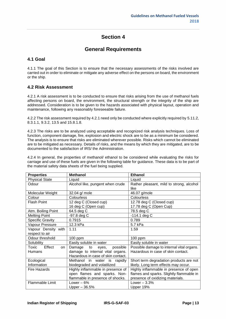
4.2 Risk Assessment 4.2.1 A risk assessment is to be conducted to ensure that risks arising from the use of methanol fuels affecting persons on board, the environment, the structural strength or the integrity of the ship are addressed. Consideration is to be given to the hazards associated with physical layout, operation and maintenance, following any reasonably foreseeable failure. 4.2.2 The risk assessment required by 4.2.1 need only be conducted where explicitly required by 5.11.2, 8.3.1.1, 9.3.2, 13.5 and 15.8.1.8. 4.2.3 The risks are to be analyzed using acceptable and recognized risk analysis techniques. Loss of function, component damage, fire, explosion and electric shock are to be as a minimum be considered. The analysis is to ensure that risks are eliminated wherever possible. Risks which cannot be eliminated are to be mitigated as necessary. Details of risks, and the means by which they are mitigated, are to be documented to the satisfaction of IRS/ the Administration. 4.2.4 In general, the properties of methanol/ ethanol to be considered while evaluating the risks for carriage and use of these fuels are given in the following table for guidance. These data is to be part of the material safety data sheets of the fuel being supplied.
Properties Methanol Ethanol
Physical State Liquid Liquid
Odour Alcohol like, pungent when crude Rather pleasant, mild to strong, alcohol like
Molecular Weight 32.04 g/ mole 46.07 g/mole
Colour Colourless Colourless
Flash Point 12 deg C (Closed cup) 16 deg C (Open cup)
12.78 deg C (Closed cup) 17.78 deg C (Open Cup)
Atm. Boiling Point 64.5 deg C 78.5 deg C
Melting Point -97.8 deg C -114.1 deg C
Specific Gravity 0.7915 0.789
Vapour Pressure 12.3 kPa 5.7 kPa
Vapour Density with respect to air
1.11 1.59
Odour threshold 100 ppm 100 ppm
Solubility Easily soluble in water Easily soluble in water
Toxic Effect on Humans
Damage to eyes, possible damage to internal vital organs. Hazardous in case of skin contact.
Possible damage to internal vital organs. Hazardous in case of skin contact.
Ecological Information
Methanol in water is rapidly biodegraded and volatilized
Short term degradation products are not likely. Long term effects may occur.
Fire Hazards Highly inflammable in presence of open flames and sparks. Non-flammable in presence of shocks.
Highly inflammable in presence of open flames and sparks. Slightly flammable in presence of oxidizing materials.
Flammable Limit Lower – 6% Upper – 36.5%
Lower – 3.3% Upper 19%

Guidelines on Methanol Fueled Vessels
2018
Indian Register of Shipping IRS-G-SAF-03 Page | 14
4.3 Limitation of Explosion Consequences 4.3.1 An explosion in any space containing any potential sources of release* and potential ignition sources shall not (Note * - Double wall fuel pipes are not considered as potential sources of release):
.1 cause damage to or disrupt the proper functioning of equipment/ systems located in any space other than that in which the incident occurs; .2 damage the ship in such a way that flooding of water below the main deck or any progressive flooding occur; .3 damage work areas or accommodation in such a way that persons who stay in such areas under normal operating conditions are injured; .4 disrupt the proper functioning of control stations and switchboard rooms necessary for power distribution; .5 damage life-saving equipment or associated launching arrangements;
.6 disrupt the proper functioning of firefighting equipment located outside the explosion-damaged space; .7 affect other areas of the vessel in such a way that chain reactions involving, inter alia, cargo, gas and bunker oil may arise; or .8 prevent access of persons to life-saving appliances or impede escape routes.

Guidelines on Methanol Fueled Vessels
2018
Indian Register of Shipping IRS-G-SAF-03 Page | 15
Section 5
Ship Design and Arrangement
5.1 Goal 5.1.1 The goal of this Section is to provide for safe location, space arrangements and mechanical protection of power generation equipment, fuel storage system, fuel supply equipment and refueling systems.
5.2 Functional Requirements 5.2.1 This Section is related to functional requirements 3.2.1, 3.2.2, 3.2.3, 3.2.5, 3.2.6, 3.2.7, 3.2.12, 3.2.14 and 3.2.16. In particular, the following apply:
.1 The fuel tank(s) are to be located in such a way that the probability for the tank(s) to be damaged following a collision or grounding is reduced to a minimum taking into account the safe operation of the ship and other hazards that may be relevant to the ship. .2 Fuel containment systems, fuel piping and other fuel release sources are to be so located and arranged that released fuel, either as vapour or liquid is led to safe locations. .3 The access or other openings to spaces containing potential sources of fuel release are to be so arranged that flammable, asphyxiating or toxic vapours or liquids cannot escape to spaces that are not designed for the presence of such substances. .4 Fuel piping is to be protected against mechanical damage. .5 The propulsion and fuel supply system is to be so designed that safety actions after any fuel leakage do not lead to an unacceptable loss of power. .6 The probability of a fire or explosion in a machinery space as a result of a fuel release is to be minimized in the design, with special attention on the risk of leakage from pumps, valves and connections.
5.3 General Requirements 5.3.1 Tanks containing fuel are not to be located within the accommodation area spaces or machinery spaces. 5.3.2 Integral fuel tanks are to be surrounded by protective secondary barriers. In the case of ships other than inland waterways ships, secondary barriers may be omitted on those tank surfaces bound by shell plating below water line and adjacent to tank connection spaces and tanks containing methanol. Subject to approval by IRS/ the Administration, secondary barriers may be omitted to void spaces without ignition sources if leakage detection and safe gas-freeing is provided. 5.3.3. The fuel containment system is to be abaft of the collision bulkhead and forward of the aft peak bulkhead. On tankers, the fuel containment system and fuel preparation rooms are to be located in cargo area. 5.3.4 Fuel tanks located on open decks are to be protected against mechanical damage. 5.3.5 Fuel tanks on open decks are to be surrounded by coamings and spills collected in a dedicated holding tank.

Guidelines on Methanol Fueled Vessels
2018
Indian Register of Shipping IRS-G-SAF-03 Page | 16
5.3.6 The maximum degree of filling of fuel tanks is to be 98 per cent by tank volume. This is the maximum allowable liquid volume relative to the tank volume to which the tank may be loaded.
5.4 Independent Fuel Tanks 5.4.1 Independent tanks may be accepted on open decks or in enclosed spaces. 5.4.2. Independent tanks are to be constructed and tested to the satisfaction of the Surveyor. 5.4.3 Independent tanks are to be fitted with:
.1 mechanical protection of the tanks depending on location and cargo operations; .2 if located on an open deck: drip tray arrangements for leak containment and water spray systems for emergency cooling; and .3 if located in an enclosed space: the space is to meet the requirements of Sections11 and 13.
5.4.4 Independent fuel tanks are to be secured to the ship's structure. The arrangement for supporting and fixing the tanks are to be designed for the maximum expected static, dynamic inclinations and accidental loads as well as the maximum expected values of acceleration, taking into account the ship characteristics and the position of the tanks. Note: The fuel containment system would be assessed in accordance with Cl. 6.4.1.6, Pt. 5, Ch. 35 of the Rules and Regulations for the Construction and Classification of Steel Ships.
5.5 Portable Tanks 5.5.1 The design of the tank is to comply with 5.4. The tank support (container frame or truck chassis) is to be designed for the intended purpose. 5.5.2 Portable fuel tanks are to be located in dedicated areas fitted with:
.1 mechanical protection of the tanks depending on location and cargo operations; .2 if located on an open deck: drip tray arrangements for leak containment and water spray systems for emergency cooling; and .3 if located in an enclosed space: the space is to meet the requirements of Sections 11 and 13.
Note: The fuel containment system would be assessed in accordance with Cl. 6.4.1.6, Pt. 5, Ch. 35 of the Rules and Regulations for the Construction and Classification of Steel Ships. 5.5.3 Portable fuel tanks are to be secured to the deck while connected to the ship systems. The arrangement for supporting and fixing the tanks are to be designed for the maximum expected static and dynamic inclinations, as well as the maximum expected values of acceleration, taking into account the ship characteristics and the position of the tanks. 5.5.4 Consideration is to be given to the ship's strength and the effect of the portable fuel tanks on the ship's stability. 5.5.5 Connections to the ship's fuel piping systems are to be made by means of approved flexible hoses suitable for methanol or other suitable means designed to provide sufficient flexibility. 5.5.6 Arrangements are to be provided to limit the quantity of fuel spilled in case of inadvertent disconnection or rupture of the non-permanent connections. 5.5.7 The pressure relief system of portable tanks is to be connected to a fixed venting system.

Guidelines on Methanol Fueled Vessels
2018
Indian Register of Shipping IRS-G-SAF-03 Page | 17
5.5.8 Control and monitoring systems for portable fuel tanks are to be integrated in the ship's control and monitoring system. Safety system for portable fuel tanks is to be integrated in the ship's safety system (e.g. shutdown systems for tank valves, leak/vapour detection systems). 5.5.9 Safe access to tank connections for the purpose of inspection and maintenance is to be ensured. 5.5.10 When connected to the ship's fuel piping system,
.1 each portable tank is to be capable of being isolated at any time; .2 isolation of one tank is not to impair the availability of the remaining portable tanks; and .3 the tank is not to exceed its filling limits.
5.6 Requirements for Machinery Spaces 5.6.1 A single failure within the fuel system is not to lead to a release of fuel into the machinery space. 5.6.2 All fuel piping within machinery space boundaries is to be enclosed in vapour tight and liquid tight enclosures in accordance with 9.4.1.
5.7 Requirements for ESD (Emergency Shutdown) Protected Machinery Spaces 5.7.1 ESD (Emergency shutdown) protection is to be limited to spaces that are defined as spaces or units not normally entered. Machinery spaces that are certified for periodically unattended operation may be accepted. 5.7.2 Measures are to be applied to protect against explosion, damage of areas outside of the machinery space and ensure redundancy of power supply. The following arrangement is to be provided but may not be limited to:
.1 gas detector; .2 shutoff valve; .3 redundancy; and .4 efficient ventilation.
5.7.3 Fuel supply piping within ESD-protected machinery spaces may be accepted without a gas and liquid tight external secondary enclosure on the following conditions:
.1 The fuel supply pressure within the piping is not exceeding 5 bar and any spray leakage will not create a hazard to persons in the space. .2 Where persons can attend the ESD protected machinery space during operation or where a spray leakage may create a fire hazard, spray shields are to be provided on all non-welded pipe connections. .3 Methanol fueled machinery for generating propulsion power and electric power are to be located in two or more machinery spaces not having any common boundaries unless it can be documented that a single casualty will not affect both spaces. .4 The machinery space is to contain only a minimum of such necessary fuel equipment, components and systems as are required to ensure that the methanol fueled machinery maintains its function. .5 A fixed vapour and liquid leakage detection system arranged to automatically shut down the fuel supply, and disconnect all electrical equipment or installations not of a certified safe type, is to be provided.

Guidelines on Methanol Fueled Vessels
2018
Indian Register of Shipping IRS-G-SAF-03 Page | 18
5.7.4 Distribution of methanol fueled machinery between the different machinery spaces is to be such that shutdown of fuel supply to any one machinery space will not lead to an unacceptable loss of power. 5.7.5 Bulkheads separating ESD protected machinery spaces are to have sufficient strength to withstand the effects of a local vapour explosion in either space, without affecting the integrity of the adjacent space and equipment within that space. 5.7.6 ESD protected machinery spaces are to be designed to provide a geometrical shape that will minimize the accumulation of gases or formation of gas pockets. 5.7.7 The ventilation system of ESD-protected machinery spaces is to be arranged in accordance with 13.5 5.7.8 Arrangements are to be provided to collect and detect liquid leakages locally and to safely drain to a collecting tank. 5.7.9 Where arrangements are such that a single failure may result in a fuel release into the machinery space, then all non-safe equipment (ignition sources) are to be automatically shut down. 5.7.10 Any equipment or machinery remaining in use or active during these conditions must be of a certified safe type.
5.8 Requirements for Location and Protection of Fuel Piping 5.8.1 Fuel pipes are not to be located less than 800 [mm] from the ship's side. 5.8.2 Fuel piping is not to be led directly through accommodation spaces, service spaces, electrical equipment rooms or control stations as defined in the SOLAS Convention. In cases where fuel piping needs to be routed through accommodation spaces, the double walled fuel piping is to be led through a dedicated duct. The duct is to be of substantial construction and be gas tight and water tight. 5.8.3 Fuel pipes led through ro-ro spaces, special category spaces and on open decks are to be protected against mechanical damage. Fuel pipes lead through ro-ro spaces are to be provided with guards or bollards to prevent vehicle collision damage. Fuel pipes in other types of cargo areas with risk of damage from cargo operations are to be similarly protected. Fuel pipes in double ducts in other areas are regarded as sufficiently protected. 5.8.4 Fuel piping is to comply with the following:
.1 The fuel pipes are to be clearly identified and fitted with shut-off valves at their connections, if any, to the fuel piping system within the cargo area; .2 The inner piping, where a protective duct is required, is to be full penetration butt welded, and fully radiographed. Flange connections in this piping are only allowed within the tank connection space and fuel preparation room or similar; .3 The bunker and supply piping is to be self-draining to the cargo area suitable fuel or collecting tanks and preferably into a fuel tank. Alternative arrangements for draining the piping may be accepted by IRS/ the Administration; .4 Arrangements are to be made to allow such piping to be purged with inert gas after use and maintained gas-safe when not in use; .5 All doors, ports and other openings on the corresponding superstructure or deckhouse side facing fuel piping are to be capable of being kept closed;

Guidelines on Methanol Fueled Vessels
2018
Indian Register of Shipping IRS-G-SAF-03 Page | 19
.6 Escape routes are not to terminate within the coamings required by 5.8.4.7 or within a distance of 3 [m] beyond the coamings; .7 Continuous coamings of suitable height are to be fitted to keep any spills on deck and away from the accommodation and service areas. .8 Fuel piping that pass through enclosed spaces in the ship is to be enclosed in a pipe that is gas tight and water tight towards the surrounding spaces with the fuel contained in the inner pipe. Such double walled piping is not required in cofferdams surrounding fuel tanks, fuel preparation rooms, spaces containing independent fuel tanks as the boundaries for these spaces will serve as a second barrier. .9 The outer pipe in the double walled fuel pipes is to be dimensioned for a design pressure not less than the maximum working pressure of the fuel pipes. As an alternative the calculated maximum built up pressure in the duct in the case of a pipe rupture may be used for dimensioning of the duct. .10 The annular space in the double walled fuel piping is to be segregated at the engine-room bulkhead. This implies that there would be no common ducting between the engine-room and other spaces.
5.8.5 Cross-connections from fuel piping to cargo liquid piping serving common systems or other tanks may be accepted provided the connections are arranged with spool pieces. The arrangement of spool pieces is to be such that even if a spool piece is unintentionally left in place, inadvertent transfer of incompatible or contaminating cargo from or to the dedicated fuel storage tank is not possible. An arrangement with swing bends would normally be the preferred spool piece arrangement to prevent unintentional transfer to or from fuel storage tanks.
5.9 Requirements for Fuel Preparation Room Design 5.9.1 Fuel preparation rooms are to be located outside the machinery spaces of category A.
5.10 Requirements for Bilge Systems 5.10.1 Bilge systems installed in areas where methanol can be present are to be segregated from the bilge system of spaces where methanol cannot be present. 5.10.2 One or more tanks for collecting drainage and any possible fuel leakages from the fuel piping and double walled pipes are to be provided. Drainage collection tanks are to comply with general requirements for fuel tanks. Means are to be provided for safely transferring the contents of drainage collection tanks to onshore reception facilities. 5.10.3 The bilge system serving the fuel preparation room is to be operable from outside the fuel preparation-room.
5.11 Requirements for Drip Trays and Holding Tanks 5.11.1 Drip trays are to be fitted where leakage and spill may occur, in particular in way of single wall pipe connections. 5.11.2 Each tray is to have a sufficient capacity to ensure that the maximum amount of spill according to the risk assessment can be handled. 5.11.3 Each drip tray is to be provided with means to safely drain spills or transfer spills to a dedicated holding tank. Means for preventing backflow from the tank are to be provided. 5.11.4 Drip trays for leakage of less than 10 liters are to be provided with means for manual emptying.
Guidelines on Methanol Fueled Vessels
2018
Indian Register of Shipping IRS-G-SAF-03 Page | 20
5.11.5 The leakage holding tank is to be equipped with a level indicator and alarm and is to be inerted at all time. 5.11.6 Bilge holding tanks are to have sufficient capacity to accommodate the maximum estimated leakage of fuel identified by the risk-assessment and agreed with IRS. 5.11.7 Drip Trays are to be provided at Bunkering Manifolds
5.12 Requirements for Arrangement of Entrances and other Openings 5.12.1 Direct access is not to be permitted from a non-hazardous area to a hazardous area. Where such openings are necessary for operational reasons, an air lock which complies with the requirements of 5.13 is to be provided. 5.12.2 Fuel preparation rooms are to have an independent access direct from open deck, where practicable. Where a separate access from open deck is not practicable, an air lock complying with 5.13 is to be provided.
5.12.3 Access to fuel equipment units not normally accessed is to be by bolted gastight manholes or covers. Technical provisions are to be made to ensure that access to the units is not possible before the unit is safely shut down, isolated from the fuel system, drained and the atmosphere is confirmed gas-free. These arrangements are subject to the approval of IRS/ the Administration. 5.12.4 Fuel tanks and surrounding cofferdams are to have suitable access from the open deck, where practicable, for gas-freeing, cleaning, maintenance and inspection. 5.12.5 The arrangement is to be such that before opening any tank or cofferdam, the tanks and cofferdams are to be gas-free. Ventilation of flammable/toxic vapour or gases is to be led to open deck. 5.12.6 For fuel tanks or surrounding cofferdams, secondary barriers and spaces not normally entered without direct access from open deck, the entry space is to comply with the following:
The entry space is to be fitted with an independent mechanical extraction ventilation system, providing a minimum of 10 air changes per hour. A low oxygen alarm and a gas detection alarm is to be fitted.
The entry space is to have sufficient open area around the fuel tank hatch for efficient evacuation and rescue operation;
Direct entry from accommodation spaces, service spaces, control stations and machinery spaces is not permitted; and
Entry from cargo spaces may be accepted depending upon the type of cargo if the area is cleared of cargo and no cargo operations are undertaken during tank entry.
5.12.7 The area around independent fuel tanks is to be sufficient to carry out evacuation and rescue operations. 5.12.8 For safe access, horizontal hatches or openings to or within fuel tanks or surrounding cofferdams are to have a minimum clear opening of 600 X 600 [mm] that also facilitates the hoisting of an injured person from the bottom of the tank/cofferdam. For access through vertical openings providing main passage through the length and breadth within fuel tanks and cofferdams, the minimum clear opening is not to be less than 600 X 800 [mm] at a height of not more than 600 [mm] from bottom plating unless gratings or footholds are provided. Smaller openings may be accepted provided evacuation of an injured person from the bottom of the tank/ cofferdam can be demonstrated.

Guidelines on Methanol Fueled Vessels
2018
Indian Register of Shipping IRS-G-SAF-03 Page | 21
5.13 Requirements for Air Locks 5.13.1 An air lock is a space enclosed by gastight bulkheads with two gastight doors spaced at least 1.5 [m] and not more than 2.5 [m] apart. Unless subject to the requirements of the International Convention on Load Line, the door sill is not to be less than 300 [mm] in height. The doors are to be self-closing without any holding back arrangements. 5.13.2 Air locks are to be mechanically ventilated at an overpressure relative to the adjacent hazardous area or space. 5.13.3 Air locks are to have a simple geometrical form. They are to provide free and easy passage, and are to have a deck area not less than 1.5 [m2]. Air locks are not to be used for other purposes, for instance as store rooms. 5.13.4 An audible and visual alarm system to give a warning on both sides of the air lock is to be provided to indicate if more than one door is moved from the closed position. 5.13.5 For non-hazardous spaces with access from hazardous spaces below deck where the access is protected by an airlock, upon loss of under pressure in the hazardous space access to the space is to be restricted until the ventilation has been reinstated. Audible and visual alarms are to be given at a manned location to indicate both loss of pressure and opening of the airlock doors when pressure is lost. 5.13.6 Essential equipment required for safety is not to be de-energized and is to be of a certified safe type. This may include lighting, fire detection, public address and general alarms systems. 5.13.7 Electrical equipment which is not of the certified safe type for propulsion, power generation, manoeuvring, anchoring and mooring equipment as well as the emergency fire pumps is not to be located in spaces to be protected by air-locks.

Guidelines on Methanol Fueled Vessels
2018
Indian Register of Shipping IRS-G-SAF-03 Page | 22
Section 6
Fuel Containment System
6.1 Goal 6.1.1 The goal of this Section is to provide for a fuel containment system where the risk to the ship, its crew and to the environment is minimized to a level that is at least equivalent to a conventional oil fueled ship.
6.2 Functional Requirements 6.2.1 This Section refers to functional requirements in 3.2.1, 3.2.2, 3.2.5 and 3.2.8 to 3.2.17. The fuel tanks are to be so designed that a leakage from the fuel tank or its connections does not endanger the ship, persons on board or the environment. Potential dangers to be avoided include:
.1 Flammable fuels spreading to locations with ignition sources; .2 Toxicity potential and risk of oxygen deficiency or other negative impacts on crew health due to fuels and inert gases; .3 Restriction of access to muster stations, escape routes and/or LSA; and .4 Reduction in availability of LSA.
6.2.2 The fuel containment system and the fuel supply system are to be so designed that safety actions after any leakage, irrespective of in liquid or vapour phase, do not lead to an unacceptable loss of power. 6.2.3 If portable tanks are used for fuel storage, the design of the fuel containment system is to be equivalent to permanent installed tanks as described in this Section.
6.3 Requirements for Fuel Tanks Venting and Gas Freeing System 6.3.1 The fuel tanks are to be fitted with a controlled tank venting system. 6.3.2 Fuel tank ventilation system is to be independent of the air pipes and venting systems of accommodation, service and control spaces, or other non-hazardous area. 6.3.3 A piping system is to be arranged to enable each fuel tank to be safely gas-freed, and to be safely filled with fuel from a gas-free condition. The system is to be arranged to minimize the possibility of pockets of gas or air remaining after changing the atmosphere. 6.3.4 Fuel tanks are to have a sufficient number of ventilation inlets and outlets to ensure complete gas freeing. Outlets for purging and aeration are to be fitted with flame screens of approved type, ref. IMO MSC/Circ.677. 6.3.5 The fuel tank is to have a minimum of two fixed pipes extended to open air for inert gas purging and gas freeing purposes. The pipes are to be self-draining. 6.3.6 The formation of gas pockets during gas freeing operation is to be avoided by considering the arrangement of internal tank structure and location of gas freeing inlets and outlets.

Guidelines on Methanol Fueled Vessels
2018
Indian Register of Shipping IRS-G-SAF-03 Page | 23
6.3.7 Each tank is to be fitted with pressure/vacuum relief valves. If pressure/vacuum relief valves are fitted to the end of the vent pipes they are to be of the high velocity type certified for endurance burning in accordance with IMO MSC/Circ.677. If pressure/vacuum relief valves are fitted in the vent line, the vent outlet is to be fitted with a flame arrestor certified for endurance burning in accordance with IMO MSC/Circ.677. 6.3.8 Shut off valves are not to be arranged either upstream or downstream of the pressure/vacuum relieve valves. By-pass valves may be provided. For temporary tank segregation purposes (maintenance) shut of valves in common vent lines may be accepted if a secondary independent over-/under pressure protection is provided to all tanks as per 6.3.9. 6.3.9 The fuel tank controlled venting system is to be designed with redundancy for the relief of full flow overpressure and/or vacuum. Pressure sensors fitted in each fuel tank, and connected to an alarm system, may be accepted in lieu of the secondary redundancy requirement for pressure relief. The opening pressure of the vacuum relief valves is not to be lower than 0.007 MPa below atmospheric pressure. 6.3.10 P/V valves are to vent to a safe location on open deck and are to be of a type which allows the functioning of the valve to be easily checked. 6.3.11 Fuel tank vent outlets are to be situated normally not less than 3 [m] above the deck. Fuel tank vent outlets are to be situated normally not less than 3[m] above gangway, if located within 4 [m] from such gangways. The vent outlets are also to be arranged at a distance of at least 10 [m] from the nearest air intake or opening to accommodation and service spaces and ignition sources. The vapour discharge is to be directed upwards in the form of unimpeded jets. 6.3.12 Vapour outlets from fuel tanks are to be provided with devices tested and type approved to prevent the passage of flame into the tank. * Due attention is to be paid in the design and position of the P/V valves with respect to blocking and due to ice during adverse weather conditions. Provision for inspection and cleaning is to be arranged. Note*: IMO MSC/Circ.677 as amended by MSC/Circ.1009; MSC.1/Circ.1324 which amends MSC/Circ.677 and MSC/Circ.1009. 6.3.13 The arrangements for gas-freeing and ventilation of fuel tanks are to be such as to minimize the hazards due to the dispersal of flammable vapours to the atmosphere and to flammable gas mixture in the tanks. The ventilation system for fuel tanks is to be exclusively for ventilating and gas freeing purposes. Connection between fuel tank and fuel preparation room ventilation will not be accepted. 6.3.14 Gas freeing operations are to be carried out such that vapour is initially discharged in one of the following ways:
.1 through outlets at least 3 m above the deck level with a vertical efflux velocity of at least 30 [m/s] maintained during the gas freeing operation; or .2 through outlets at least 3 m above the deck level with a vertical efflux velocity of at least 20 [m/s] which are protected by suitable devices to prevent the passage of flame.

Guidelines on Methanol Fueled Vessels
2018
Indian Register of Shipping IRS-G-SAF-03 Page | 24
6.3.15 In designing a gas-freeing system in conformity with 6.4.9, particularly in order to achieve the required exit velocities of 6.4.9.1 and 6.4.9.2, due consideration is to be given to the following:
.1 materials of construction of system;
.2 time to gas-free;
.3 flow characteristics of fans to be used;
.4 the pressure losses created by ducting, piping, fuel tank inlets and outlets;
.5 the pressure achievable in the fan driving medium (e.g. water or compressed air); and
.6 the densities of the fuel vapour/air mixtures for the range of cargoes to be carried. 6.3.16 The fuel tank vent system is to be sized to permit bunkering at a design loading rate without over pressuring the fuel tank. 6.3.17 The fuel tank vent system is to be connected to the highest point of each tank and vent lines are to be self-draining under all normal operating conditions.
6.4 Inerting and Atmospheric Control within the Fuel Storage System 6.4.1 Inerting of the vapour space of the fuel tank and piping under normal operation is to be provided. 6.4.2 Fuel tanks and surrounding cofferdams are to be arranged for inert gas purging to ensure a flammable atmosphere is not present. Secondary barriers, double bottoms, cofferdams, duct keels, pipe tunnels, hold spaces and other spaces where methanol may accumulate are to be capable of being ventilated to ensure a safe environment when entry into the spaces is necessary. 6.4.3 The system is to be designed to eliminate the possibility of a flammable mixture atmosphere existing in the fuel tank during any part of the atmosphere change operation, vapour freeing or inerting by utilizing an inerting medium. 6.4.4 Arrangements to prevent back-flow of fuel vapour into the inert gas system are to be provided as specified in 6.4.5 and 6.4.6. 6.4.5 To prevent the return of flammable liquid and vapour to the inert gas system, the inert gas supply line is to be fitted with two shutoff valves in series with a venting valve in between (double block and bleed valves). In addition, a closable non-return valve is to be installed between the double block and bleed arrangement and the fuel system. These valves are to be located inside hazardous spaces. 6.4.6 Where the connections to the inert gas piping systems are non-permanent, two non-return valves may substitute the valves required in 6.4.5. Fuel tank connections for inert gas padding are considered as permanent for the purpose of this requirement. 6.4.7 Blanking arrangements are to be fitted in the inert gas supply line to individual tanks. The position of the blanking arrangements is to be immediately obvious to personnel entering the tank. Blanking is to be via removable spool piece.
Guidelines on Methanol Fueled Vessels
2018
Indian Register of Shipping IRS-G-SAF-03 Page | 25
6.5 Inert Gas Availability on Board 6.5.1 Nitrogen inert gas is to be available permanently on board in order to achieve at least one trip from port to port considering maximum consumption of fuel expected and maximum length of trip expected and to keep tanks inerted during two weeks in harbour with minimum port consumption. A production plant and/or adequate storage capacities might be used to achieve the defined availability target. 6.5.2 The equipment is to be capable of producing nitrogen inert gas with oxygen content at no time greater than 5% by volume. A continuous-reading oxygen content meter is to be fitted to the inert gas supply from the equipment and is to be fitted with an alarm set at a maximum of 5%. 6.5.3 The system is to be able to maintain an atmosphere with an oxygen content not exceeding [5%] by volume in any part of any fuel tank. 6.5.4 The inert gas system is to have pressure controls and monitoring arrangements appropriate to the fuel containment system. 6.5.5 Where a nitrogen generator or nitrogen storage facilities are installed in a separate compartment outside of the engine-room, the separate compartment is to be fitted with an independent mechanical extraction ventilation system, providing a minimum of 6 air changes per hour. If the oxygen content is below 19% in the separate compartment an alarm is to be given. A minimum of two oxygen sensors are to be provided in each space. Visual and audible alarm is to be placed at each entrance to the inert gas room. 6.5.6 Nitrogen pipes are only to be led through well ventilated spaces. Nitrogen pipes in enclosed spaces are to:
have only a minimum of flange connections as needed for fitting of valves and be fully welded otherwise; and
be as short as possible. 6.5.7 Notwithstanding the requirements of 6.5, nitrogen inert gas utilized for gas freeing of tanks may be provided externally to the ship.

Guidelines on Methanol Fueled Vessels
2018
Indian Register of Shipping IRS-G-SAF-03 Page | 26
Section 7
Material and General Pipe Design
7.1 Goal 7.1.1 The goal of this Section is to ensure the safe handling of fuel, under all operating conditions, to minimize the risk to the ship, personnel and to the environment, having regard to the nature of the products involved.
7.2 Functional Requirements 7.2.1 This Section relates to functional requirements 3.2.1, 3.2.5, 3.2.6, 3.2.8, 3.2.9 and 3.2.10, of these guidelines. In particular, the following apply:
.1 All materials used are to be suitable for the fuel under the maximum working pressure and temperature.
7.3 Requirements for General Pipe Design 7.3.1 The design pressure for any section of the fuel piping system is the maximum gauge pressure to which the system may be subjected in service, taking into account the highest set pressure on any relief valve on the system. The design pressure P in the formula for t0 in 7.3.2 is the maximum gauge pressure to which the system may be subjected in service, taking into account the highest set pressure on any relief valve on the system. 7.3.2 The minimum wall thickness is to be calculated as follows: t = (t0 + b + c) / (1 – a/100) [mm] where: t0 = theoretical thickness, mm t0 = PD / (2Ke + P) [mm] with :
P = system design pressure, but not less than the design pressure given in 7.3.1, [MPa] D = outside pipe diameter, [mm] K = allowable stress [N/mm2], See 7.3.3 e = Efficiency factor equal to 1.0 for seamless pipes and for longitudinally or spirally welded pipes, delivered by approved manufacturers of welded pipes, which are considered equivalent to seamless pipes when non-destructive testing on welds is carried out in accordance with recognized standards. In other cases, an efficiency factor less than 1.0, in accordance with recognized standards, may be required depending upon the manufacturing process. b = allowance for bending (mm). The value for b shall be chosen so that the calculated stress in the bend, due to internal pressure only, does not exceed the allowable stress. Where such justification is not given, b shall not be less than: b = D∙t0 / 2.5r [mm] with r = mean radius of the bend [mm]; c = corrosion allowance [mm]. If corrosion or erosion is expected, the wall thickness of piping is to be increased over that required by the other design requirements. a = negative manufacturing tolerance for thickness (%).

Guidelines on Methanol Fueled Vessels
2018
Indian Register of Shipping IRS-G-SAF-03 Page | 27
7.3.3 For pipes the allowable stress K to be considered in the formula for t0 in 7.3.2 is the lower of the following values
Rm / A or Re / B Where: Rm = specified minimum tensile strength at ambient temperature (N/mm2). Re = specified minimum yield stress at ambient temperature (N/mm2). If stress-strain curve does not show a defined yield stress, the 0.2% proof stress applies. A and B have values of at least A = 2.7 and B = 1.8
7.3.4 Where necessary for mechanical strength to prevent damage, collapse, excessive sag or buckling of pipes due to superimposed loads, the wall thickness is to be increased over that required by 7.3.2 or, if this is impracticable or would cause excessive local stresses, these loads are to be reduced, protected against or eliminated by other design methods. Such superimposed loads may be due to; supports, ship deflections, liquid pressure surge during transfer operations, the weight of suspended valves, reaction to loading arm connections, or otherwise. 7.3.5 For pipes made of materials other than steel, the allowable stress would be specially considered by IRS. 7.3.6 High pressure fuel piping systems are to have sufficient constructive and fatigue strength. This is to be confirmed by carrying out stress analysis and taking into account:
.1 stresses due to the weight of the piping system; .2 acceleration loads when significant; and .3 internal pressure and loads induced by hog and sag of the ship.
7.3.7 Fuel pipes and all the other piping needed for a safe and reliable operation and maintenance is to be colour marked in accordance with a standard at least equivalent to those acceptable to IRS/ the Administration*. Note: * Refer to EN ISO 14726:2008 Ships and marine technology – identification colours for the content of piping systems 7.3.8 All fuel piping and independent fuel tanks are to be electrically bonded to the ship's hull. Electrical conductivity is to be maintained across all joints and fittings. Electrical resistance between piping and the hull is to be not more than 10^6 Ohm. 7.3.9 Piping other than fuel supply piping and cabling may be arranged in the double wall piping or duct provided that they do not create a source of ignition or compromise the integrity of the double pipe or duct. The double wall piping or duct is to only contain piping or cabling necessary for operational purposes. 7.3.10 Filling lines to fuel tanks are to be arranged to minimize the possibility for static electricity e.g. by reducing the free fall into the fuel tank to a minimum.

Guidelines on Methanol Fueled Vessels
2018
Indian Register of Shipping IRS-G-SAF-03 Page | 28
7.3.11 Flexibility of piping 7.3.11.1 The arrangement and installation of fuel piping is to provide the necessary flexibility to maintain the integrity of the piping system in the actual service situations, taking potential for fatigue into account. Expansion bellows are not to be used. 7.3.12 Piping fabrication and joining details 7.3.12.1 Piping for fuel is to be joined by welding except
.1 for approved connections to shut off valve and expansion joints, if fitted; and .2 for other exceptional cases specifically approved by IRS/ the Administration.
7.3.12.2 The following direct connections of pipe length without flanges may be considered .1 Butt-welded joints with complete penetrations at the root; .2 Slip-on welded joints with sleeves and related welding having dimensions in accordance with recognized standards shall only be used in pipes having an external diameter of 50 mm or less. The possibility for corrosion to be considered; and .3 Screwed connections, in accordance with recognized standards, are only to be used for piping with an external diameter of 25 [mm] or less.
Press fitting joints, in accordance with recognized standards, may be used for external pipe diameters of DN50 [mm] or less, subject to the approval of IRS/ the Administration. 7.3.12.3 Welding, post-weld heat treatment, radiographic testing, dye penetrating testing, pressure testing, leakage testing and non-destructive testing is to be performed in accordance with recognized standards. Butt welding is to be subject to 100% non-destructive testing, while sleeve welds are to be subject to at least 10% liquid penetrant testing (PT) or magnetic particle testing (MT). 7.3.12.4 All valves and expansion joints used in high pressure fuel systems are to be approved according to a recognized standard acceptable to IRS/ the Administration. 7.3.12.5 Flanged piping connections Where flanges are used they are to be of the welded neck or slip-on type. Socket welds are not to be used in nominal sizes above 50 [mm]. 7.3.12.6 Expansion joints Expansion of piping shall normally be allowed for by the provision of expansion loops or bends in the fuel piping system. Slip joints are not to be used. 7.3.12.7 Other connections Piping connections are to be joined in accordance with 7.3.12.2 but for other exceptional cases the alternative arrangements may be specially considered by IRS/ the Administration.
7.4 Requirements for Materials 7.4.1 Metallic materials for methanol service 7.4.1.1 Due consideration is to be taken with respect to the corrosive nature of methanol when contaminated with water. 7.4.1.2 In general, requirements for materials are to be in accordance with Part 2 of the IRS Rules and Regulations for the Construction and Classification of Steel Ships.

Guidelines on Methanol Fueled Vessels
2018
Indian Register of Shipping IRS-G-SAF-03 Page | 29
7.4.1.3 Materials that are sensitive to methanol and methanol containing water such as Aluminium alloys, galvanized steel, lead alloys are not to be used in systems containing methanol fuel. In methanol based applications, SS 316L grade or a titanium or molybdenum stabilized grade of SS 316L grade steel is recommended. Weld integrity can become an issue due to presence of water and inorganic salts that can lead to corrosion within heat affected zones of the welds. It may be noted that methanol can cause stress corrosion cracking in titanium alloys. 7.4.2 Non-metallic Materials for methanol service 7.4.2.1 Materials, for tank coatings and tank access hatch sealing are to be resistant to:
(a) Methanol liquid (b) Methanol where it may contain water (c) Methanol vapour (d) Nitrogen gas used for inerting
7.4.2.2 Fluorinated materials such as Teflon may be used as equipment components in methanol service. Rubbers such as EPDM and neoprene are considered suitable for methanol service. Nitrile and butyl rubbers are not to be used in systems containing methanol fuel. The rubber hoses are to have an internal coil wire for strength and electrical continuity and are to be compatible with methanol service. All hoses are to be clearly labelled ‘For methanol service only’. Hose ends are to be capped or protected by other suitable means to avoid contamination during storage. Also note 8.3.2.3 and 8.3.2.4 for other storage and draining requirements. 7.4.2.3 Requirements for testing of hoses are indicated in 8.3.2. For first time use, the hose and piping should be washed with water and then methanol to ensure that contaminants are removed before being placed into service. 7.4.3 Metallic materials for ethanol service 7.4.3.1 Metallic materials such as stainless steel, bronze are considered compatible with ethanol. Metallic materials such as zinc, aluminium, brass, lead and lead based alloys are considered unsuitable for ethanol applications. 7.4.4 Non-metallic materials for ethanol service
7.4.4.1 Non-metallic materials such as Buna-N, nitrile rubber, neoprene, polypropylene, viton, teflon, and thermoset reinforced fiber glass may be used for ethanol applications. 7.4.4.2 Non-metallic materials such as natural rubber, polyurethane, polyvinyl chloride, polyamides, methyl methacrylate plastics and polyester bonded fiberglass laminates are not considered suitable for ethanol service.

Guidelines on Methanol Fueled Vessels
2018
Indian Register of Shipping IRS-G-SAF-03 Page | 30
Section 8
Bunkering
8.1 Goal 8.1.1 The goal of this Section is to provide for suitable systems on board the ship to ensure that bunkering can be conducted without causing danger to persons, the environment or the ship.
8.2 Functional Requirements 8.2.1 This Section relates to functional requirements 3.2.1, 3.2.2, 3.2.3, 3.2.4, 3.2.5, 3.2.6, 3.2.7, 3.2.8, 3.2.9, 3.2.10, 3.2.11, 3.2.13, 3.2.14, 3.2.15, 3.2.16 and 3.2.17 of these guidelines. In particular, the following apply: 8.2.1.1 The piping system for transfer of fuel to the fuel tank is to be designed such that any leakage from the piping system cannot cause danger to the persons onboard, the environment or the ship.
8.3 Requirements for Bunkering Station 8.3.1 General requirements 8.3.1.1 The bunkering station is to be located on open deck so that sufficient natural ventilation is provided. Closed or semi-enclosed bunkering stations should be subject to special consideration within the risk assessment. Closed or semi-enclosed bunkering stations are to be protected against the sea. 8.3.1.2 Entrances, air inlets and openings to accommodation, service and machinery spaces and control stations are not to face methanol/ ethanol fuel bunkering shore connections. The methanol/ ethanol fuel bunkering shore –connection is to be located at a distance of at least 4% of the length of the ship but not less than 3 [m] from the end of the house facing the methanol/ethanol shore-connection location. This distance however need not exceed 5 [m]. Side scuttles and windows facing the fuel shore connection location within the distance mentioned above are to be the fixed (non-opening) type except for the wheel house so long as they are designed that a rapid and efficient gas and vapour tightening of the wheelhouse can be ensured. In addition, during the use of bunkering arrangements, all doors, ports and other openings on the corresponding superstructure or deckhouse side are to be kept closed. Where, in the case of small ships, compliance with this clause is not possible, relaxation from the above requirements will be specially considered by IRS/ Administration 8.3.1.3 Closed or semi-enclosed bunkering stations are to be surrounded by gastight boundaries against enclosed spaces. 8.3.1.4 Bunkering lines are not to be led directly through accommodation, control stations or service spaces. Bunkering lines passing through non-hazardous areas in enclosed spaces are to be double walled or located in gas-tight ducts. 8.3.1.5 Arrangements are to be made for safe management of fuel spills. Coamings and/ or drip trays are to be provided below the bunkering connections together with a means of safely collecting and storing spills. This could be a drain to a dedicated holding tank equipped with a level indicator and alarm. Where coamings or drip trays will be subject to rain water, provisions are to be made to drain rain water overboard. 8.3.1.6 Showers and eye wash stations for emergency usage are to be located in close proximity to areas where the possibility for accidental contact with fuel exists. The emergency showers and eye wash stations to be operable under all ambient conditions.

Guidelines on Methanol Fueled Vessels
2018
Indian Register of Shipping IRS-G-SAF-03 Page | 31
8.3.2 Ships’ Bunker Hoses 8.3.2.1 Bunker hoses carried on board are, to be suitable for methanol and certified to a minimum bursting pressure of 5 times the normal working pressure. 8.3.2.2 Each new type of bunker hose, complete with end-fittings, is to be prototype-tested at a normal ambient temperature, with 200 pressure cycles from zero to at least twice the specified maximum working pressure. After this cycle pressure test has been carried out, the prototype test is to demonstrate a bursting pressure of at least 5 times its specified maximum working pressure at the upper and lower extreme service temperature. Hoses used for prototype testing are not to be used for bunker service. Thereafter, before being placed in service, each new length of bunker hose produced is to be hydrostatically tested at ambient temperature to a pressure not less than 1.5 times its specified maximum working pressure, but not more than two fifths of its bursting pressure. The hose is to be stencilled, or otherwise marked, with the date of testing, its specified maximum working pressure and, if used in services other than ambient temperature services, its maximum and minimum service temperature, as applicable. The specified maximum working pressure is not to be less than 1 MPa gauge. All hoses are to be clearly labelled ‘For methanol service only”. 8.3.2.3 Means are to be provided for draining any fuel from the bunkering hoses upon completion of operation. 8.3.2.4 Where fuel hoses are to be carried on board, arrangements are to be made for safe storage of the hoses. Hoses are to be stored on the open deck or in a storage room with an independent mechanical extraction ventilation system, providing a minimum of 6 air changes per hour.
8.4 Requirements for Manifold 8.4.1 The bunkering manifold is to be designed to withstand the external loads during bunkering. The connections at the bunkering station are to be of dry-disconnect type equipped with additional safety dry break-away coupling/self-sealing quick release.
8.5 Requirements for Bunkering System 8.5.1 Means are to be provided for draining any fuel from the bunkering pipes upon completion of operation. 8.5.2 Means are to be provided to gas free and inert bunker lines. When not engaged in bunkering, the bunkering pipes are to be free of gas, unless the consequences of not gas freeing is evaluated and approved. 8.5.3 The ship is to be fitted with a bunkering Emergency Shutdown (ESD) system operable from both the ship and the bunker supply facility. This is to be arranged to ensure rapid and safe shutdown of the bunker supply system without release of liquid or vapour. 8.5.4 In the bunkering line, as close to the connection point as possible, there is to be a manually operated stop valve and a remotely operated shutdown valve arranged in series. Alternatively, a combined manually operated and remote shutdown valve may be provided. It is to be possible to operate this remotely operated valve from the bunkering control station. 8.5.5 Where bunkering pipes are arranged with a cross-over suitable isolation arrangements are to be provided to ensure that fuel cannot be transferred inadvertently to the ship side not in use for bunkering.

Guidelines on Methanol Fueled Vessels
2018
Indian Register of Shipping IRS-G-SAF-03 Page | 32
8.6 Bunker Delivery Note 8.6.1 In general, a non-exhaustive list of specific properties and data of methanol to be addressed in the Bunker Delivery Note is as follows:
o Specific gravity;
o acidity as acetic acid;
o alkalinity;
o carbonyl compound;
o evaporation residue content;
o fuel temperature delivered;
o fuel temperature in storage tank(s);
o calorific value (lower/higher);
o flammability limits and range;
o flashpoint value;
o vapour density;
o boiling temperature;
o auto-ignition temperature;
o toxicity;
o sulphur content; and
o by-products.

Guidelines on Methanol Fueled Vessels
2018
Indian Register of Shipping IRS-G-SAF-03 Page | 33
Section 9
Fuel Supply to Consumers
9.1 Goal 9.1.1 The goal of this Section is to ensure safe and reliable distribution of fuel to the consumers.
9.2 Functional Requirements 9.2.1 This Section is related to functional requirements 3.2.1, 3.2.2, 3.2.3, 3.2.4, 3.2.5, 3.2.6, 3.2.8, 3.2.9, 3.2.10, 3.2.11, 3.2.13, 3.2.14, 3.2.15, 3.2.16 and 3.2.17 of these guidelines. In particular, the following apply:
9.3 General Requirements for Fuel Supply System 9.3.1 The fuel piping system is to be separate from all other piping systems. 9.3.2 The fuel supply system is to be so arranged that the consequences of any release of fuel will be minimized, while providing safe access for operation and inspection. The causes and consequences of release of fuel are to be subject to special consideration within the risk assessment in 4.2. 9.3.3 The piping system for fuel transfer to the consumers is to be designed in a way that a failure of one barrier cannot lead to a leak from the piping system into the surrounding area causing danger to the persons on board, the environment or the ship. 9.3.4 Fuel lines are to be installed and protected so as to minimize the risk of injury to persons on board in case of leakage.
9.4 Requirements for Fuel Distribution 9.4.1 All piping containing fuel passing through enclosed spaces is to be double walled. The outer pipe or duct is to be gas tight and water tight. Such double walled piping is not required in cofferdams surrounding fuel tanks, or in spaces or units not normally accessed or fuel preparation-rooms or other fuel treatment spaces considered as hazardous. 9.4.2 The annular space between inner and outer pipe is to have mechanical ventilation of under pressure type with a capacity of minimum 30 air changes per hour and be ventilated to open air. Appropriate means for detecting leakage into the annular space is to be provided. The double wall enclosure is to be connected to a suitable draining tank allowing the collection and the detection of any possible leakage. 9.4.3 Inerting of the annular space might be accepted as an alternative to ventilation. The inert gas pressure in the annular space is to be higher than the maximum pressure in the inner pipe. Appropriate means of detecting leakage into the annular space is to be provided. Suitable alarms are to be provided to indicate a loss of inert gas pressure between the pipes. 9.4.4 Other solutions providing an equivalent safety level may be accepted by IRS/ the Administration. 9.4.5 The outer pipe in the double walled fuel pipes is to be dimensioned for a design pressure not less than the maximum working pressure of the fuel pipes. As an alternative the calculated maximum built up pressure in the duct in the case of an inner pipe rupture may be used for dimensioning of the duct.

Guidelines on Methanol Fueled Vessels
2018
Indian Register of Shipping IRS-G-SAF-03 Page | 34
9.5 Redundancy of Fuel Supply 9.5.1 Propulsion and power generation arrangements, together with fuel supply systems are to be arranged with full redundancy and segregation all the way from the fuel tanks to the consumer, so that a leakage in one system failure in fuel supply does not lead to an unacceptable loss of power. 9.5.2 Two fuel service tanks for each type of fuel used on board necessary for propulsion and vital systems of equivalent arrangements are to be provided. Each tank is to have a capacity sufficient for continuous rating of the propulsion plant and normal operating load at sea of the generator plant for a minimum period of 8 hours. Other arrangements with the same level of redundancy may be accepted by the Administration.
9.6 Safety Functions of the Fuel Supply System 9.6.1 All fuel piping is to be arranged for gas-freeing and inerting. 9.6.2 Fuel tank inlet and outlet valves are to be as close to the tank as possible. Valves required to be operated under normal operation such as when fuel is supplied to consumers or during bunkering are to be remotely operated if not easily accessible. 9.6.3 The main fuel supply line to each consumer or set of consumers are to be equipped with an automatically-operated master fuel valve. The master fuel valve(s) is to be situated in the part of the piping that is outside the machinery space containing methanol fueled consumer(s). The master fuel valve(s) is to automatically shut off the fuel supply in accordance with 15.2.1.2 and Table 15.1 in Section 15. 9.6.4 Means of manual emergency shutdown of fuel supply to the consumers or set of consumers are to be provided at a reasonable number of places in the engine room on the primary and secondary escape routes from the consumer compartment, at a location outside the consumer space, outside the fuel preparation room and at the bridge. The activation device is to be arranged as a physical button, duly marked and protected against inadvertent operation and operable under emergency lighting. 9.6.5 The fuel supply line to each consumer is to be provided with a remote operated double block and bleed/ drain valve to be fitted after the master fuel valve but before the consumer. The requirements for alarm and shut down are indicated in Table 15.1 in Section 15. 9.6.6 There is to be one manually operated shut down valve in the fuel line to each consumer to ensure safe isolation during maintenance. 9.6.7 In the event of a failure, valves are to fail to a safe position. 9.6.8 When pipes penetrate the fuel tank below the top of the tank a remotely operated shut-off valve shall be fitted to the fuel tank bulkhead. When the fuel tank is adjacent to a fuel preparation room, the valve may be fitted on the tank bulkhead on the fuel preparation room side.
9.7 Requirements for Fuel Preparation Rooms and Pumps 9.7.1 Any fuel preparation room is to be located outside the engine-room, be gas tight and liquid tight to surrounding enclosed spaces and vented to open air. 9.7.2 Hydraulically powered pumps that are submerged in fuel tanks are to be arranged with double barriers preventing the hydraulic system serving the pumps from being directly exposed to methanol. The double barrier is to be arranged for detection and drainage of eventual methanol leakage. 9.7.3 All pumps in the fuel system are to be protected against running dry (i.e., protected against operation in the absence of fuel or service fluid). All pumps which are capable of developing a pressure exceeding the design pressure of the system are to be provided with relief valves. Each relief valve is to be in closed circuit, i.e., arranged to discharge back to the piping upstream of the suction side of the pump and to effectively limit the pump discharge pressure to the design pressure of the system.

Guidelines on Methanol Fueled Vessels
2018
Indian Register of Shipping IRS-G-SAF-03 Page | 35
Section 10
Power Generation including Propulsion and other Energy
Consumers
10.1 Goal 10.1.1 To provide safe and reliable delivery of mechanical, electrical or thermal energy.
10.2 Functional Requirements 10.2.1 This Section is related to functional requirements as described in 3.2.1, 3.2.11, 3.2.13, 3.2.14, 3.2.16, 3.2.17 and 3.2.18. In particular, the following apply:
.1 The exhaust system is to be designed to prevent any accumulation of unburnt fuel. .2 Each fuel consumer is to have a separate exhaust system.
10.2.2 One single failure in the fuel system is not to lead to an unacceptable loss of power.
10.3 General 10.3.1 All engine components and engine related systems are to be designed in such a way that fire and explosion risks are minimized. 10.3.2 Engine components containing methanol fuel are to be effectively sealed to prevent leakage of fuel into the machinery space. 10.3.3 For trunk and two stroke otto cycle engines running on methanol, crankcase is to be equipped with gas detection. 10.3.4 Means are to be provided to monitor and detect poor combustion or misfiring. In the event that it is detected, continued operation may be allowed provided that the fuel supply to the concerned cylinder is shut off and provided that the operation of the engine with one-cylinder cut-off is acceptable with respect to torsional vibrations. 10.3.5 Special attention is to be paid to the corrosive nature of methanol while selecting materials used in engine components.
10.4 Dual-Fuel Engines 10.4.1 In case of shutoff of the methanol supply, the engines are to be capable of continuous operation by oil fuel only without interruption. 10.4.2 An automatic system is to be fitted to change over from methanol mode to oil fuel-only mode and vice versa with minimum fluctuation of the engine power. Acceptable reliability is to be demonstrated through testing. In the case of unstable operation on engines when methanol firing, the engine is to automatically change to oil fuel mode. There shall also be possibility for manual change over. 10.4.3 In case of an emergency stop or a normal stop the methanol fuel is to be automatically shut off not later than the pilot oil fuel. It shall not be possible to shut off the pilot oil fuel without first or simultaneously closing the fuel supply to each cylinder or to the complete engine.

Guidelines on Methanol Fueled Vessels
2018
Indian Register of Shipping IRS-G-SAF-03 Page | 36
10.5 Single Fuel Engines 10.5.1 In case of a normal stop or an emergency shutdown, the methanol fuel supply is to be shut off not later than the ignition source. It is not to be possible to shut off the ignition source without first or simultaneously closing the fuel supply to each cylinder or to the complete engine.
10.6 Methanol-Fueled Boilers
10.6.1 The arrangement of boilers and burner systems is to comply with the requirements of Pt 4, Ch 5
Boilers and Pressure Vessels, Pt.4, Ch.3 Pumping and Piping of the Rules and Regulations for the
Construction and Classification of Steel Ships, as applicable. The whole boiler casing is to be gastight
and each boiler is to have a separate uptake.
10.6.2 Combustion chambers and furnaces of boilers are to be designed such that pockets of fuel
cannot accumulate.
10.6.3 Boilers and combustion units are to be provided with forced draught arrangements. Each boiler
is to have its own forced draught system.
10.6.4 Means are to be provided so that, in the event of flame failure, the fuel supply to the burners is
shut-off automatically, and alarms are activated.
10.6.5 Means are to be provided for automatically purging the fuel supply piping to the burners after the
burners have been extinguished. Arrangements are also to be provided to allow manual purging.
Interlocking devices are to be fitted to ensure that purging can be performed only when the burner fuel
supply valves are closed.
10.6.6 For dual-fuel burner units, the firing equipment is to be suitable to burn either fuel oil or methanol
alone, or fuel oil and methanol simultaneously. The burner is to maintain stable firing under all firing
conditions and on main/propulsion boilers are to be fitted with an automatic fuel changeover system to
change from methanol to oil operation with minimum impact to the flame.
10.6.7 The fuel changeover system is to be monitored and protected from damage (e.g. from high
pressure, heat, electrical overload) so as to ensure continuous availability whilst the boiler is in
operation. An interlocking device is to be provided to prevent the methanol fuel supply being opened
until the oil and air controls are in the firing position. It is to be possible to change from methanol to fuel
oil operation without interruption of boiler firing.
10.6.8 Each burner supply pipe is to be fitted with a fuel shut-off valve and a flame arrestor, unless this
s incorporated in the burner.
10.6.9 In addition to the low water-level oil-fuel shut-off and alarm required by Pt 5, Ch 5, 3.5; Low water
level fuel shut-off or equivalent arrangements are to be made for fuel shut-off and alarms when the
boilers are operating on methanol

Guidelines on Methanol Fueled Vessels
2018
Indian Register of Shipping IRS-G-SAF-03 Page | 37
Section 11
Fire Safety
11.1 Goal 11.1.1 The goal of this Section is to provide fire protection, detection and fighting for all systems related to storing, handling, transfer and use of methanol as fuel.
11.2 Functional Requirements 11.2.1 This Section is related to functional requirements in 3.2.1, 3.2.2, 3.2.4, 3.2.5, 3.2.12, 3.2.14, 3.2.15 and 3.2.17.
11.3 General Requirements 11.3.1 The requirements in this Section are additional to those given in SOLAS Ch. II-2.
11.4 Fire Protection 11.4.1 For the purposes of fire protection, fuel preparation rooms are to be regarded as machinery space of category A. 11.4.2 The fire integrity of spaces mentioned in 11.4.1 having boundaries towards accommodation, control station and/or cargo areas is not to be less than A-60. 11.4.3 Any boundary of accommodation up to navigation bridge windows, service spaces, control stations, machinery spaces and escape routes, facing fuel tanks on open deck is to have A-60 fire integrity. 11.4.4 For fire integrity the fuel tank boundaries are to be separated from the machinery spaces of category-A and other rooms with high fire risks by a cofferdam of at least 900 [mm] with insulation of not less than A-60 class. 11.4.5 The bunkering station is to be separated by A-60 class divisions towards machinery spaces of category A, accommodation, control stations and high fire risk spaces, except for spaces such as tanks, voids, auxiliary machinery spaces of little or no fire risk, sanitary and similar spaces where the insulation standard may be reduced to class A-0.
11.5 Fire Main 11.5.1 When the fuel storage tank(s) is located on the open deck, isolating valves are to be fitted in the fire main in order to isolate damaged sections of the fire main. Isolation of a section of fire main is not to deprive the fire line ahead of the isolated section from the supply of water.
11.6 Firefighting 11.6.1 Where fuel tanks are located on open deck, there is to be a fixed firefighting system of alcohol resistant aqueous film forming foam (ARAFFF) type. The system is to be operable from a safe position. The system is to fulfil the requirements in Chapter 14 of the FSS Code. 11.6.2 The ARAFFF type foam firefighting is to cover the area below the fuel tank where a large spill of fuel can be expected to spread.

Guidelines on Methanol Fueled Vessels
2018
Indian Register of Shipping IRS-G-SAF-03 Page | 38
11.6.3 The bunker station is to have a fixed fire extinguishing system of alcohol resistant aqueous film forming foam (ARAFFF) type with 6% proportioning with water and a portable dry chemical powder extinguisher or an equivalent extinguisher, located near the entrance of the bunkering station. 11.6.4 Where fuel tanks are located on open deck, there is to be a fixed water spray system for diluting eventual large spills, cooling and fire prevention. The system is to cover exposed parts of the fuel tank. 11.6.5 A suitable fixed fire detection and fire alarm system is to be provided for all compartments containing the methanol fuel system. 11.6.6 Suitable detectors are to be selected based on the fire characteristics of the fuel. Smoke detectors are to be used in combination with detectors which can detect methanol/ethanol fire.
11.7 Fire Extinguishing of Engine-Room and Pump-Room 11.7.1 Machinery space and fuel preparation room where methanol fueled engines or fuel pumps are arranged are to be protected by an approved fixed fire extinguishing system in accordance with SOLAS Reg.II-2/10 and the FSS Code. In addition, the fire extinguishing medium used is to be suitable for the extinguishing of methanol fires. 11.7.2 An approved alcohol resistant foam system covering the tank top and bilge area under the floor plates is to be arranged for machinery space category A and fuel preparation room containing methanol. 11.7.3 Regardless of the requirements in 11.7.1 and 11.7.2, fire extinguishing system against methanol fires may be arranged based on the risk assessment.

Guidelines on Methanol Fueled Vessels
2018
Indian Register of Shipping IRS-G-SAF-03 Page | 39
Section 12
Explosion Prevention and Area Classification
12.1 Goal 12.1.1 The goal of this Section is to provide for the prevention of explosions and for the limitation of effects of a fire and explosion.
12.2 Functional Requirements 12.2.1 This Section is related to functional requirements 3.2.1, 3.2.2, 3.2.3, 3.2.4, 3.2.5, 3.2.6, 3.2.8, 3.2.11, 3.2.12, 3.2.13, 3.2.14, 3.2.15, 3.2.16 and 3.2.17 of these guidelines. The probability of explosions is to be reduced to a minimum by:
.1 reducing the number of sources of ignition; .2 reducing the probability of formation of ignitable mixtures and .3 the use of certified safe type electrical equipment suitable for the hazardous zone where the use of electrical equipment in hazardous areas is unavoidable.
12.3 General Requirements 12.3.1 Hazardous areas on open deck and other spaces not addressed in this section are to be analyzed and classified based on applicable requirements of a standard such as IEC standard 60092-502, part 4.4: Tankers carrying flammable liquefied gases. The electrical equipment fitted within hazardous areas is to be according to the same standard. 12.3.2 Electrical equipment and wiring is in general not be installed in hazardous areas unless essential for operational purposes and based on a recognized standard.* (Note*: The type of equipment and installation requirements should comply with IEC standard 60092-502: IEC 60092-502:1999 Electrical Installations in Ships – Tankers – Special Features and IEC 60079-10-1:2008 Explosive atmospheres – Part 10-1: Classification of areas – Explosive gas atmospheres, according to the area classification). 12.3.3 All hazardous areas are to be inaccessible to passengers and unauthorized crew at all times.
12.4 Area Classification 12.4.1 Area classification is a method of analyzing and classifying the areas where explosive gas atmospheres may occur. The object of the classification is to allow the selection of electrical apparatus able to be operated safely in these areas. Areas and spaces other than those classified in 12.5, shall be subject to special consideration. The principles of the IEC-standards are to be applied. 12.4.2 In order to facilitate the selection of appropriate electrical apparatus and the design of suitable electrical installations, hazardous areas are divided into zones 0, 1 and 2.* See 12.5 below. (Note*: Refer to standards IEC 60079-10-1:2008 Explosive atmospheres Part 10-1: Classification of areas – Explosive gas atmospheres and guidance and informative examples given in IEC 60092-502:1999, Electrical Installations in Ships – Tankers – Special Features for tankers). 12.4.3 Ventilation ducts are to have the same area classification as the ventilated space.

Guidelines on Methanol Fueled Vessels
2018
Indian Register of Shipping IRS-G-SAF-03 Page | 40
12.5 Hazardous Area Zones 12.5.1 Hazardous area zone 0 12.5.1.1 This zone includes, but is not limited to:
.1 the interiors of methanol fuel tanks, any pipework for pressure-relief or other venting systems for fuel tanks, pipes and equipment containing methanol fuel. .2 Instrumentation and electrical apparatus in contact with methanol fuel or gas should be of a type suitable for Zone 0. Temperature sensors installed in thermos wells, and pressure sensors without additional separating chamber should of intrinsically safe type Ex ia.
12.5.2 Hazardous area zone 1 (Note* : Instrumentation and electrical apparatus installed within these areas should be of a type suitable for zone 1) 12.5.2.1 This zone includes, but is not limited to:
.1 cofferdams and other protective spaces surrounding the fuel tanks; .2 fuel preparation rooms; .3 areas on open deck, or semi-enclosed spaces on deck, within 3 [m] of any methanol fuel tank outlet, gas or vapour outlet, bunker manifold valve, other methanol fuel valve, methanol fuel pipe flange, methanol fuel preparation room ventilation outlets; .4 Areas on open deck or semi-enclosed spaces on deck in the vicinity of the fuel tank P/V outlets, within a vertical cylinder of unlimited height and 6 [m] radius centred upon the centre of the outlet and within a hemisphere of 6 [m] radius below the outlet; .5 areas on open deck or semi-enclosed spaces on deck, within 1.5 [m] of fuel preparation room entrances, fuel preparation room ventilation inlets and other openings into zone 1 spaces; .6 areas on the open deck within spillage coamings surrounding methanol fuel bunker manifold valves and 3 [m] beyond these, up to a height of 2.4 [m] above the deck; .7 enclosed or semi-enclosed spaces in which pipes containing methanol/ethanol fuel are located, e.g. ducts around methanol fuel pipes, semi-enclosed bunkering stations; .8 a space protected by an airlock is considered as non-hazardous area during normal operation, but will require equipment required to operate following loss of differential pressure between the protected space and the hazardous area to be certified as suitable for zone 1; and
12.5.3 Hazardous area zone 2* (Note*: Instrumentation and electrical apparatus installed within these areas should be of a type suitable for zone 2) 12.5.3.1 This zone includes, but is not limited to:
.1 areas 4 [m] beyond the cylinder and 4 [m] beyond the sphere defined in 12.5.2.1.4] .2 areas within 1.5 [m] surrounding other open or semi-enclosed spaces of zone 1 defined in
12.5.2.1; and .3 air locks between Hazardous Area Zone 1 and a non-Hazardous Area.
Guidelines on Methanol Fueled Vessels
2018
Indian Register of Shipping IRS-G-SAF-03 Page | 41
Section 13
Ventilation
13.1 Goal 13.1.1 The goal of this Section is to provide for the ventilation required for safe working conditions for personnel and the safe operation of machinery and equipment where methanol is used as fuel.
13.2 Functional Requirements 13.2.1 This Section is related to functional requirements in 3.2.1, 3.2.2, 3.2.4, 3.2.6, 3.2.11 to and 3.2.17.
13.3 General 13.3.1 Any ducting used for the ventilation of hazardous spaces is to be separate from that used for the ventilation of non-hazardous spaces. ‘Fail-safe’ automatic closing fire dampers of an approved type are to be fitted in all ventilation trunks serving hazardous areas. The characteristics of the ‘fail-safe’ operation are to be evaluated, not only on the basis of the function of the fire damper, but also the availability of the machinery and systems within the space that it serves. The ventilation is to function at all temperatures and environmental conditions the ship will be operating in. 13.3.2 Electric motors for ventilation fans are not to be located in ventilation ducts for hazardous spaces unless the motors are certified for the same hazard zone as the space served. 13.3.3 Design of ventilation fans serving spaces where vapours from fuels may be present is to fulfil the following:
.1 ventilation fans are not to produce a source of vapour ignition in either the ventilated space or the ventilation system associated with the space. Ventilation fans and fan ducts, in way of fans only, are to be of non-sparking construction defined as:
.1 impellers or housings of non-metallic material, due regard being paid to the elimination of static electricity; .2 impellers and housings of non-ferrous metals; .3 impellers and housings of austenitic stainless steel; .4 impellers of aluminium alloys or magnesium alloys and a ferrous (including austenitic stainless steel) housing on which a ring of suitable thickness of non-ferrous materials is fitted in way of the impeller, due regard being paid to static electricity and corrosion between ring and housing; or
.5 any combination of ferrous (including austenitic stainless steel) impellers and
housings with not less than 13 [mm] tip design clearance. .2 in no case is the radial air gap between the impeller and the casing to be less than 0.1 of the diameter of the impeller shaft in way of the bearing but not less than 2 [mm]. The gap need not be more than 13 [mm]; .3 any combination of an aluminium or magnesium alloy fixed or rotating component and a ferrous fixed or rotating component, regardless of tip clearance, is considered a sparking hazard and is not to be used in these places.

Guidelines on Methanol Fueled Vessels
2018
Indian Register of Shipping IRS-G-SAF-03 Page | 42
13.3.4 Ventilation systems required to avoid any vapour accumulation is to consist of independent fans, each of sufficient capacity, unless otherwise specified in these guidelines. The ventilation system is to be of a mechanical exhaust type, with extraction inlets located such as to avoid accumulation of vapor from leaked methanol in the space. 13.3.5 Air inlets for hazardous enclosed spaces are to be taken from areas that, in the absence of the considered inlet, would be non-hazardous. Air inlets for non-hazardous enclosed spaces are to be taken from non-hazardous areas at least 1.5 [m] away from the boundaries of any hazardous area. Where the inlet duct passes through a more hazardous space, the duct is to be gas-tight and have over-pressure relative to this space. 13.3.6 Air outlets from non-hazardous spaces are to be located outside hazardous areas. 13.3.7 Air outlets from hazardous enclosed spaces are to be located in an open area that, in the absence of the considered outlet, would be of the same or lesser hazard than the ventilated space. 13.3.8 The required capacity of the ventilation plant is normally based on the total volume of the room. An increase in required ventilation capacity may be necessary for rooms having a complicated form. 13.3.9 Non-hazardous spaces with entry openings to a hazardous area are to be arranged with an air-lock and be maintained at overpressure relative to the external hazardous area. The overpressure ventilation is to be arranged according to the following:
.1 during initial start-up or after loss of overpressure ventilation, before energizing any electrical installations not certified safe for the space in the absence of pressurization, it shall be required to:
.1 proceed with purging (at least 5 air changes) or confirm by measurements that the space is non-hazardous; and .2 pressurize the space.
.2 operation of the overpressure ventilation is to be monitored and in the event of failure of the overpressure ventilation:
.1 an audible and visual alarm is to be given at a manned location; and
.2 if overpressure cannot be immediately restored, automatic or programmed, disconnection of electrical installations according to a recognized standard* would be required.
(Note* - IEC 60092-502:1999 Electrical Installations in Ships – Tankers – Special Features, Table 5 (Ch.8.4.5), may be referred)
13.3.10 Non-hazardous spaces with entry openings to a hazardous enclosed space are to be arranged with an air-lock and the hazardous space is to be maintained at under-pressure relative to the non-hazardous space. Operation of the extraction ventilation in the hazardous space is to be monitored and in the event of failure of the extraction ventilation:
.1 an audible and visual alarm is to be given at a manned location; and .2 if under-pressure cannot be immediately restored, automatic or programmed, disconnection of electrical installations according to a recognized standard in the non-hazardous space shall be required.

Guidelines on Methanol Fueled Vessels
2018
Indian Register of Shipping IRS-G-SAF-03 Page | 43
13.4 Requirements for Fuel Preparation Space 13.4.1 Fuel preparation spaces are to be provided with an effective mechanical forced ventilation system of extraction type. During normal operation the ventilation is to be at least 30 air changes per hour. 13.4.2 The number and power of the ventilation fans is to be such that the capacity is not reduced by more than 50%, if a fan with a separate circuit from the main switchboard or emergency switchboard or a group of fans with common circuit from the main switchboard or emergency switchboard, is inoperable. 13.4.3 Ventilation systems for fuel preparation rooms and other fuel handling spaces are to be in operation when pumps or other fuel treatment equipment are working.
13.5 Requirements for Bunkering Station 13.5.1 Bunkering stations that are not located on open deck are to be suitably ventilated to ensure that any vapour being released during bunkering operations will be removed outside. If the natural ventilation is not sufficient, the bunkering stations are to be subject to special consideration with respect to requirements for mechanical ventilation. IRS/ the Administration may require special risk assessment.
13.6 Requirements for Ducts and Double Wall Pipes 13.6.1 Ducts and double wall pipes containing fuel piping fitted with mechanical ventilation system of the extraction type, are to be provided with a ventilation capacity of at least 30 air changes per hour. 13.6.2 The ventilation system for double wall piping and ducts is to be independent of all other ventilation systems. 13.6.3 The ventilation inlet for the double wall piping or duct is always to be located in a non-hazardous area, in open air, away from ignition sources. The inlet opening is to be fitted with a suitable wire mesh guard and protected from ingress of water.
Guidelines on Methanol Fueled Vessels
2018
Indian Register of Shipping IRS-G-SAF-03 Page | 44
Section 14
Electrical Installations
14.1 Goal 14.1.1 The goal of this Section is to provide for electrical installations that minimizes the risk of ignition in the presence of a flammable atmosphere.
14.2 Functional Requirements 14.2.1 This Section is related to functional requirements in 3.2.1, 3.2.2, 3.2.3, 3.2.5, 3.2.8, 3.2.11, 3.2.13, 3.2.16, 3.2.17 and 3.2.18.
14.3 General 14.3.1 Electrical installations are to comply with a recognized national or international standard, such as the IEC 60092 series of standards. 14.3.2 Electrical equipment or wiring is not to be installed in hazardous areas unless essential for operational purposes or safety enhancement. 14.3.3 Where electrical equipment is installed in hazardous areas as provided in 14.3.2 it is to be selected, installed and maintained in accordance with IEC standards or other standards, such as the IEC 60092-502 standard. 14.3.4 The lighting system in hazardous areas is to be divided between at least two branch circuits. All switches and protective devices are to interrupt all poles or phases and are to be located in a non-hazardous area. 14.3.5 The installation on board of the electrical equipment units is to be such as to ensure the safe bonding to the hull of the units themselves. 14.3.6 Hoses, transfer arms, piping and fittings provided by the delivering facility used for bunkering are to be electrically continuous, suitably insulated and are to provide a level of safety compliant with recognized standards.

Guidelines on Methanol Fueled Vessels
2018
Indian Register of Shipping IRS-G-SAF-03 Page | 45
Section 15
Control Monitoring and Safety Systems
15.1 Goal 15.1.1 The goal of this Section is to provide for the arrangement of control, monitoring and safety systems that support an efficient and safe operation of the fuel installations as covered in the other chapters of these guidelines.
15.2 Functional Requirements 15.2.1 This section is related to functional requirements in 3.2.1, 3.2.2, 3.2.3, 3.2.9, 3.2.10, 3.2.11, 3.2.13, 3.2.14, 3.2.15 and 3.2.17.
.1 The control, monitoring and safety systems of the methanol installations are to be so arranged that there is not an unacceptable loss of power in the event of a single failure; .2 A fuel safety system is to be arranged to close down the fuel supply system automatically, upon failure in systems as described in Table 15.1 and upon other fault conditions which may develop too fast for manual intervention; .3 The safety functions are to be arranged in a dedicated fuel safety system that is independent of the fuel control system in order to avoid possible common cause failures. This includes power supplies and input and output signal; .4 The safety systems including the field instrumentation are to be arranged to avoid spurious shutdown, e.g. as a result of a faulty vapour detector or a wire break in a sensor loop; and .5 Where two fuel supply systems are required to meet the regulations, each system is to be fitted with its own set of independent fuel control and safety systems.
15.3 General Requirements 15.3.1 Suitable instrumentation devices are to be fitted to allow a local and a remote reading of essential parameters to ensure a safe management of the whole fuel equipment including bunkering. 15.3.2 Liquid leakage detection is to be installed in the protective cofferdams/ secondary barrier surrounding the fuel tanks, in all ducts around fuel pipes, in fuel preparation rooms, and in other enclosed spaces containing single walled fuel piping or other fuel equipment. At least one bilge well with a level indicator is to be provided for each enclosed space, where an independent storage tank(s) without a protective cofferdam/ secondary barrier is (are) located. A high-level bilge alarm is to be provided. The leakage detection system is to trigger an alarm and the safety functions in accordance with Table 15.1. 15.3.3 For tanks not permanently installed in the vessel a monitoring system equivalent to that provided for permanent installed tanks is required.
15.4 Requirements for Bunkering and Fuel Tank Monitoring 15.4.1 Level indicators for fuel tanks
.1 Each fuel tank is to be fitted with closed level gauging device(s), arranged to ensure a level reading is always obtainable whenever fuel is contained in the tank.

Guidelines on Methanol Fueled Vessels
2018
Indian Register of Shipping IRS-G-SAF-03 Page | 46
.2 Unless necessary maintenance can be carried out while the fuel tank is in service, two devices are to be installed.
15.4.2 Overflow control during bunkering and gas freeing by water:
.1 Each fuel tank is to be fitted with a visual and audible high level alarm. This is to be able to be function tested from the outside of the tank and can be common with the level gauging system (configured as an alarm on the gauging transmitter), but is to be independent of the high-high level alarm. The alarm shall generally activate at 95% volume of tank. .2 An additional sensor (high-high level) operating independently of the high liquid level alarm is to automatically actuate a shutoff valve to prevent the tank from becoming liquid full. The alarm with activation of valve shut-off shall activate at 98% volume of tank. This is to be able to be function tested from the outside of the tank. .3 The high and high-high level alarm for the fuel tanks are to be visual and audible at the location of bunkering manifolds and at which gas-freeing by water filling of the fuel tanks is controlled, given that water filling is the preferred method for gas-freeing.
15.5 Requirements for Bunkering Control 15.5.1 Bunkering control is to be from a safe remote location. At this safe remote location:
Tank pressure and tank level is to be capable of being monitored.
The remote control valves required by 8.5.3 and 11.6 are to be capable of being operated from this location. Closing of the bunkering shutdown valve is to be possible from the control location for bunkering and from another safe location.
Overfill alarms and automatic shutdown are also to be indicated at this location. 15.5.2 If the ventilation in the ducting enclosure or annular spaces of the double walled bunkering lines stops, an audible and visual alarm is to be activated at the bunkering control location. 15.5.3 If fuel leakage is detected in ducting enclosure or the annular spaces of the double walled bunkering lines an audible and visual alarm and emergency shutdown of the bunkering valve is to be activated automatically.
15.6 Requirements for Fuel Transfer Pump Monitoring 15.6.1 Fuel transfer pumps are to be fitted with audible and visual alarms both on the navigation bridge in the engine control room and in the fuel preparation room. As a minimum the alarms are to include low fuel output pressure and fuel pump operation.
15.7 Requirements for Engine Monitoring 15.7.1 In addition to the instrumentation provided in accordance with SOLAS Chapter II-1, part C, indicators are to be fitted on the navigation bridge, the engine control room and the manoeuvring platform for:
.1 operation of the engine in case of methanol fuel only engines; .2 operation and mode of operation of the engine in the case of dual fuel engines.

Guidelines on Methanol Fueled Vessels
2018
Indian Register of Shipping IRS-G-SAF-03 Page | 47
15.8 Requirements for Gas Detection
15.8.1 Permanently installed gas detectors are to be fitted in: .1 in all ventilated annular spaces of the double walled fuel pipes; .2 in machinery spaces containing methanol piping, fuel equipment or consumers; .3 in fuel preparation rooms; .4 other enclosed spaces containing fuel piping or other fuel equipment without ducting; .5 other enclosed or semi-enclosed spaces where fuel vapours may accumulate; .6 in cofferdams surrounding fuel tanks; .7 air locks; and .8 at ventilation inlets to accommodation and machinery spaces if required based on the risk assessment required in 4.2
15.8.2 Gas detectors are in general not required in spaces where fuel piping is completely ducted. 15.8.3 The number of detectors in each space are to be considered taking into account the size, layout and ventilation of the space. 15.8.4 Independent gas detector systems are to be fitted for each required methanol supply system. 15.8.5 The detection equipment is to be located where vapour may accumulate and/or in the ventilation outlets. 15.8.6 Fuel vapour detection equipment is to be designed, installed and tested in accordance with a recognized standard. * (Note* : IEC 60079-29-1 – Explosive atmospheres – Gas detectors – Performance requirements of detectors for flammable detectors). 15.8.7 An audible and visible alarm is to be activated at a fuel vapour concentration of 20% of the lower explosion limit (LEL). The safety system is to be activated at 40% of LEL at two detectors. 15.8.8 For ventilated ducts and annular spaces around fuel pipes in the machinery spaces containing methanol-fueled engines, the alarm limit is to be set to 20% LEL. The safety system is to be activated at 40% of LEL at two detectors. 15.8.9 Audible and visible alarms from the fuel vapour detection equipment are to be located on the navigation bridge, in the continuously manned central control station, safety center and at the control location for bunkering as well as locally. 15.8.10 Fuel vapour detection required by this section is to be on the basis of continuous monitoring of all gas detector locations in a cyclic manner.
15.9 Requirements for Fire Detection 15.9.1 Fire detection in machinery space containing methanol engines and rooms containing independent tanks for methanol storage are to give audible and visual alarms.

Guidelines on Methanol Fueled Vessels
2018
Indian Register of Shipping IRS-G-SAF-03 Page | 48
15.10 Requirements for Ventilation 15.10.1 Any loss of the required ventilating capacity is to give an audible and visual alarm on the navigation bridge and in a continuously manned central control station or safety centre as well as locally.
15.11 Requirements on Safety Functions of Fuel Supply Systems 15.11.1 If the fuel supply is shut off due to activation of an automatic valve, the fuel supply is not to be opened until the reason for the disconnection is ascertained and the necessary precautions taken. A readily visible notice giving instruction to this effect is to be placed at the operating station for the shut-off valves in the fuel supply lines. 15.11.2 If a fuel leak leading to a fuel supply shutdown occurs, the fuel supply is not to be operated until the leak has been found and dealt with. Instructions to this effect are to be placed in a prominent position in the machinery space. 15.11.3 Full stop of ventilation in the double pipe supplying methanol to single fuel engines is to lead the following action:
.1 If another methanol supply system is arranged, the one with defect ventilation is to shutdown as soon as the other supply system is ready to deliver.
15.11.4 A caution placard or signboard is to be permanently fitted in the machinery space containing methanol -fueled engines stating that heavy lifting, implying danger of damage to the fuel pipes, is not to be done when the engine(s) is running on methanol . 15.11.5 Pumps and fuel supply are to be arranged for manual remote emergency stop from the following locations as applicable:
.1 navigation bridge;
.2 cargo control room;
.3 on-board safety centre;
.4 engine control room;
.5 fire control station; and
.6 adjacent to the exit of fuel preparation spaces

Guidelines on Methanol Fueled Vessels
2018
Indian Register of Shipping IRS-G-SAF-03 Page | 49
Table 15.1 : Monitoring of Methanol supply system
Parameter Alarm Automatic shutdown of
tank valve (valves
referred to in 9.6.2)
Automatic shutdown of master fuel
valve (valves referred to in
9.6.3)
Automatic shutdown of
bunkering valve
Comments
High level fuel tank X See 15.4.2.1
High, high level fuel tank
X X See 15.4.2.2 and 15.5.1
Loss of ventilation in the annular space in the bunkering line
X X See 15.5.2
Gas detection in the annular space in the bunkering line
X X See 15.5.3
Loss of ventilation in ventilated areas
X See 15.10
Manual shutdown X See 15.5.1
Liquid methanol detection in the annular space of the double walled bunkering pipe
X X See 15.5.3
Vapour detection in ducts around fuel pipes
X See 15.7.1.1
Vapour detection in cofferdams surrounding fuel tanks. One detector giving 20% of LEL
X See 15.8.1.6
Vapour detection in crankcase and above stuffing box
X See 15.8.1.5
Vapour detection in air locks
X See 15.8.1.7
Vapour detection in cofferdams surrounding fuel tanks. Two detectors giving 40% of LEL, 1)
X X X See 15.8.1.6
Vapour detection in ducts around double walled pipes, 20% LEL
X See 15.8.8
Vapour detection in ducts around double walled pipes, 40% of LEL, 1), 2)
X X X See 15.8.8 Two gas detectors to give min 40% LEL before shut down

Guidelines on Methanol Fueled Vessels
2018
Indian Register of Shipping IRS-G-SAF-03 Page | 50
Table 15.1 (Contd.)
Parameter Alarm Automatic shutdown of
tank valve (valves
referred to in 9.6.2)
Automatic shutdown of master fuel
valve (valves referred to in
9.6.3)
Automatic shutdown of
bunkering valve
Comments
Liquid leak detection in annular space of double walled pipes
X X X See 15.3.2
Liquid leak detection in engine-room
X X See 15.3.2
Liquid leak detection in pump-room
X X See 15.3.2
Liquid leakage detection in protective cofferdams surrounding fuel tanks
X See 15.3.2
Footnotes to be considered to differentiate the safety requirements: 1) Two independent detectors located close to each other are required for redundancy reasons. If the detector is of self-monitoring type the installation of a single gas detector can be permitted. 2) If the fuel is supplied to more than one engine and the different supply pipes are completely separated and fitted in separate ducts and with the master valves fitted outside of the duct and outside of the machinery space containing gas-fuelled engines, only the master valve on the supply pipe leading into the duct where gas or loss of ventilation is detected shall close.
Guidelines on Methanol Fueled Vessels
2018
Indian Register of Shipping IRS-G-SAF-03 Page | 51
Section 16
Testing and Trials
16.1 Testing and trials of consumers and equipment is to be carried out in accordance with test schedules agreed with IRS. In general, the arrangements for testing would be equivalent to those required for oil-fueled machinery and equipment. 16.2 Commissioning tests and trials would be carried out in accordance with the tests and trials program, as required to be submitted by Section 2, 2.4 and agreed by IRS. All tests and trials are to be carried out in the presence of a Surveyor. 16.3 Trials are to include the testing of all alarms and safeguards associated with the fuel supply system and consumers and equipment. At first loading, the testing of high and high-high level alarms is to be conducted by raising the liquid level in the fuel tank to the alarm point. All elements of the level alarms, including the electrical circuit and the sensor(s), of the high and high-high alarms, are to be function tested.

Guidelines on Methanol Fueled Vessels
2018
Indian Register of Shipping IRS-G-SAF-03 Page | 52
Section 17
Drills and Emergency Exercises
17.1.1 Drills and emergency exercises on board are to be conducted at regular intervals. Exercises related to low flash point fuels, such as methanol are to at least include following:
.1 tabletop exercise; .2 review of fueling procedures based in the fuel handling manual required by 18.2.3 .3 responses to potential contingences; .4 tests of equipment intended for contingency response; and .5 reviews that assigned seafarers are trained to perform assigned duties during fueling, operation and contingency response. Methanol related exercises are to be incorporated into periodical drills required by resolution IMO Resolution A.741(18)
17.1.2 The response and safety system for hazards and accident control is to be reviewed and tested. All staff onboard are to be trained as per STCW. 17.1.3 The master, officers, ratings and other personnel on ship using low-flash point fuels are to be trained and qualified in accordance to the Reg. V/3 of the STCW Convention and Section A-V/3 of the STCW Code taking into account the specific hazards of the methanol used as fuel.
Guidelines on Methanol Fueled Vessels
2018
Indian Register of Shipping IRS-G-SAF-03 Page | 53
Section 18
Operation
18.1 Goal The goal of this Section is to ensure that operational procedures for the loading, storage, operation, maintenance, and inspection of systems for methanol/ethanol fuels, minimize the risk to personnel, the ship and the environment and that are consistent with practices for a conventional oil fueled ship whilst taking into account the nature of these fuels.
18.2 Functional Requirements This section relates to the functional requirements in 3.2.1 to 3.2.3, 3.2.9, 3.2.11, 3.2.15, 3.2.16 and 3.2.17. In particular, the following apply:
.1 a copy of these Guidelines, or national regulations incorporating the provisions of the same, shall be on board every ship covered by these Guidelines; .2 maintenance procedures and information for all methanol/ethanol related installations are to be available on board; .3 the ship is to be provided with operational procedures including a suitably detailed fuel handling manual, such that trained qualified personnel can safely operate the fuel bunkering, storage and transfer systems; and .4 the ship is to be provided with suitable emergency procedures.
18.3 Maintenance 18.3.1 Maintenance and repair procedures are to include considerations with respect to the fuel containment system and adjacent spaces. 18.3.2 In-service survey, maintenance and testing of the fuel containment system is to be carried out in accordance with the inspection/survey plan as approved by the Administration. 18.3.3 The procedures and information are to include maintenance of electrical equipment that is installed in explosion hazardous spaces and areas. The inspection and maintenance of electrical installations in explosion hazardous spaces are to be performed in accordance with a recognized standard such as IEC 60079 17:2007 Explosive atmospheres – part 17: Electrical installations inspection and maintenance.)
18.4 Bunkering Operations 18.4.1 Responsibilities 18.4.1.1 Before any bunkering operation commences, the master of the receiving ship or his representative and the representative of the bunkering source (Persons In Charge, PIC) are to:
.1 agree in writing the transfer procedure including the maximum transfer rate at all stages and volume to be transferred; .2 agree in writing action to be taken in an emergency; and .3 complete and sign the bunker safety check-list.

Guidelines on Methanol Fueled Vessels
2018
Indian Register of Shipping IRS-G-SAF-03 Page | 54
18.4.1.2 Upon completion of bunkering operations the ship PIC is to receive and sign a Bunker Delivery Note for the fuel delivered, and signed by the bunkering source PIC. It is recommended that the bunkering is a manned operation. 18.4.2 Overview of control, automation and safety systems
18.4.2.1 The fuel handling manual required by 18.2.3 is to include, but is not limited to:
.1 overall operation of the ship from dry-dock to dry-dock, including procedures for bunker loading and, where appropriate, discharging, sampling, inerting and gas freeing; risks related to potential spillage (drip trays, deck drains, etc.) are to be considered. .2 operation of inert gas systems; .3 firefighting and emergency procedures: operation and maintenance of firefighting systems and use of extinguishing agents; .4 specific fuel properties and special equipment needed for the safe handling of the particular fuel; .5 fixed and portable gas detection operation and maintenance of equipment; .8 6 emergency shutdown systems, where fitted; and .9 7 a description of the procedural actions to take in an emergency situation, such as leakage, fire or poisoning.
18.4.2.2 A fuel system schematic/piping and instrumentation diagram (P&ID) is to be reproduced and permanently displayed in the ship's bunker control station and at the bunker station.
18.4.3 Pre-bunkering verification
18.4.3.1 Prior to conducting bunkering operations, pre-bunkering verification including, but not limited to the following, is to be carried out and documented in the bunker safety checklist:
.1 all communications methods, including ship shore link (SSL), if fitted; .2 operation of fixed fire detection equipment; .3 operation of portable vapor detection equipment .4 readiness of fixed and portable firefighting systems and appliances .5 operation of remote controlled valves; and .6 inspection of hoses and couplings.
18.4.3.2 Documentation of successful verification is to be indicated by the mutually agreed and executed bunkering safety checklist signed by both PIC's.
18.4.4 Ship bunkering source communications
18.4.4.1 Communications are to be maintained between the ship PIC and the bunkering source PIC at all times during the bunkering operation. In the event that communications cannot be maintained, bunkering is to stop and not resume until communications are restored.

Guidelines on Methanol Fueled Vessels
2018
Indian Register of Shipping IRS-G-SAF-03 Page | 55
18.4.4.2 Communication devices used in bunkering are to comply with recognized standards for such devices acceptable to the Administration.
18.4.4.3 PIC's are to have direct and immediate communication with all personnel involved in the bunkering operation.
18.4.4.4 The ship shore link (SSL) or equivalent means to a bunkering source provided for automatic ESD communications, is to be compatible with the receiving ship and the delivering facility ESD system. Refer to ISO 28460, ship-shore interface and port operations. 18.4.5 Electrical bonding
Hoses, transfer arms, piping and fittings provided by the delivering facility used for bunkering are to be electrically continuous, suitably insulated and shall provide a level of safety compliant with recognized standards. Electrical isolation between ship and shore may be considered. API RP 2003 :Protection Against Ignitions Arising Out of Static, Lightning, and Stray Currents and ISGOTT: International Safety Guide for Oil Tankers and Terminals may be referred in this regard.