lng fuelled vessels design training - on the mos way fueled vessels design training by ... lng...
TRANSCRIPT
Lecture Notes on
LNG Fueled Vessels Design Training by
Dr Evangelos K. Boulougouris
Mr Leonidas E. Chrysinas
OTMW-N Module 1
Glasgow July 2015

1

2
3
Contents
List of Figures ....................................................................................................................................... 6
List of Table .......................................................................................................................................... 9
1. Background .................................................................................................................................... 10
1.1. European Policy for Maritime Transport and Supply Chain ............................................. 10
1.1.1. LNG infrastructure of filling stations and deployment in ships ............................. 11
1.1.2. LNG in Baltic Sea Ports ............................................................................................. 12
1.1.3. CO2 & Ship Transport emissions Abatement through LNG, COSTA .................. 13
1.2. LNG Fuelled Vessels Working Group .................................................................................. 14
1.3. EU project “MARCO POLO” and EIB ................................................................................ 14
1.4. Environmental regulations concerning the Shipping industry ........................................... 15
1.5. Emission Control Area (ECAs) .............................................................................................. 19
2. Shipping industry overview........................................................................................................... 21
2.1. Shipping industry and European Seas .................................................................................. 22
2.2. Shipping industry in the Mediterranean Sea ....................................................................... 24
3. Compliance Strategies of Owners with the Regulations ............................................................. 26
3.1. Scrubber................................................................................................................................... 26
3.2. MGO fuel type ......................................................................................................................... 28
3.3. LNG .......................................................................................................................................... 28
3.3.1. LNG engine choices ..................................................................................................... 30
3.4. Investment and operational costs for alternative fuel solutions ......................................... 30
3.4.1. Investment costs and compliance strategies ............................................................. 31
3.4.2. Operational expenses for various compliance strategies ......................................... 32
3.5. Expenditure on LNG supplies and competitive fuel types .................................................. 34
3.5.1. Historical Prices and price relationships of HFO, LNG and MGO ....................... 34
4. LNG supply chain .......................................................................................................................... 37
4.1. Up-Stream LNG Supply Chain .............................................................................................. 38
4
4.1.1. Natural gas facilities in Europe.................................................................................. 38
4.1.2. LNG import terminals ................................................................................................ 42
4.1.3. Locations of existing LNG terminals ......................................................................... 43
4.2. Down-Stream LNG Supply Chain ......................................................................................... 44
4.2.1. Intermediary LNG Terminals.................................................................................... 46
4.2.2. Small and Medium-sized LNG carriers for refueling .............................................. 47
4.2.3. Special tankers for Regional LNG Distribution ....................................................... 60
4.2.4. LNG transport via pipelines....................................................................................... 61
4.2.5. Gas Conversion to Liquid .......................................................................................... 62
4.3. LNG Solutions for LNG bunkering ....................................................................................... 62
4.3.1. Ship-to-ship (STS) Bunkering .................................................................................... 63
4.3.2. Truck-to-Ship bunkering, TTS .................................................................................. 65
4.3.3. LNG Terminal-to-Ship via pipeline, TPS ................................................................. 66
4.3.4. LNG Mobile LNG Storage Tanks.............................................................................. 67
4.3.5. Appropriate methods for refueling various ship classes ......................................... 68
4.3.6. Advantages and Disadvantages of Different Refueling Methods ........................... 69
5. Design of LNG fueled vessel .......................................................................................................... 70
5.1. Philosophy of Design ............................................................................................................... 70
5.1.1. What is Design? ........................................................................................................... 70
5.1.2. The Design Team......................................................................................................... 70
5.1.3. What is Design Philosophy? ....................................................................................... 71
5.2. LNG Engine Choices ............................................................................................................... 73
5.2.1. Four-Stroke Dual Fuel Engine (Circle Otto) ............................................................ 74
5.2.2. Two-Stroke Dual Fuel Engines (Diesel) .................................................................... 76
5.2.3. Characteristics of Dual Fuel Engines (low pressure-high pressure) ...................... 78
5.2.4. Fuel Gas Engine (Single Fuel Gas Engines) .............................................................. 79
5.3. LNG Tanks .............................................................................................................................. 80

5
5.3.1. Membrane Tanks ........................................................................................................ 82
5.3.2. Independent Tanks ..................................................................................................... 83
5.3.2.1. Type A ....................................................................................................................... 84
5.3.2.2. Type B ....................................................................................................................... 84
5.3.2.3. Type C ....................................................................................................................... 85
5.3.3. Management of Boil-off Gas ...................................................................................... 87
5.3.4. LNG Tank Location .................................................................................................... 91
5.3.5. Filling limits ................................................................................................................. 95
5.4. Process Systems ....................................................................................................................... 96
5.5. Engine, LNG Storage and Security Systems Layout ......................................................... 100
6. Existing Vessels Powered with LNG .......................................................................................... 103
6.1. M/S Viking Grace ................................................................................................................. 103
6.2. Case Study: Hamworthy Baltic Design Centre, Project No. 3103 .................................... 107
6.3. Case study for a generic Cruise ship ................................................................................... 109
6.4. DNV GL Study about Retrofitting Cruise Ships to LNG by Elongation ......................... 112
7. Standards and Guidelines for Natural Gas Fuelled Ship Projects .......................................... 126
7.1. Project Development ............................................................................................................. 126
7.2. Design ..................................................................................................................................... 131
7.3. Operations ............................................................................................................................. 139
7.4. Training ................................................................................................................................. 144
References ......................................................................................................................................... 147
6
List of Figures
Figure 1. Motorways of Sea Map ....................................................................................................... 11
Figure 2. The countries and the wider areas with direct benefit from the "COSTA" ................. 13
Figure 3. Regulations imposing sulfur limits and the corresponding deadlines in accordance
with Annex VI by MARPOL.............................................................................................................. 17
Figure 4. Constraints for Tier I-II-III regarding emissions NOX ................................................... 18
Figure 5. Comprehensive overview of all upcoming environmental regulations for shipping
industry ................................................................................................................................................ 18
Figure 6. Existing and possible future ECA areas ........................................................................... 20
Figure 7. Major sea routes in 2007 .................................................................................................... 21
Figure 8. The number of total calls of ships to the ports of the EEA and Russia (Baltic Sea) ..... 23
Figure 9. (a) Crude oil transport routes, (b) Commercial container transport routes and central
port capacity ........................................................................................................................................ 25
Figure 10. A typical design of "dry SOX scrubber system". The physical dimensions is in
relation to the main engine. ................................................................................................................ 27
Figure 11. Comparison of NOX, SO2, CO2, PM emissions for alternative fuel oil types ............ 29
Figure 12. M/T Bit Viking .................................................................................................................. 33
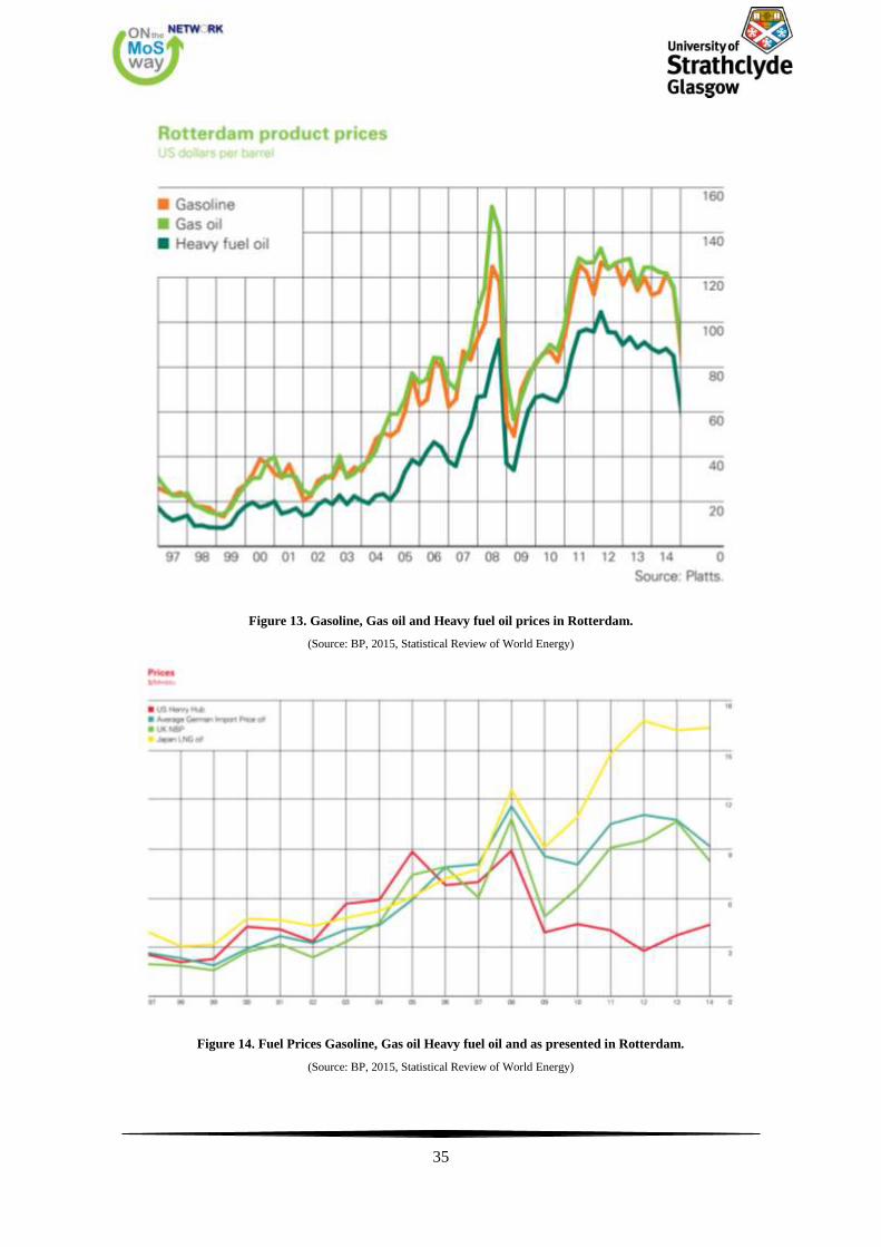
Figure 13. Gasoline, Gas oil and Heavy fuel oil prices in Rotterdam............................................. 35
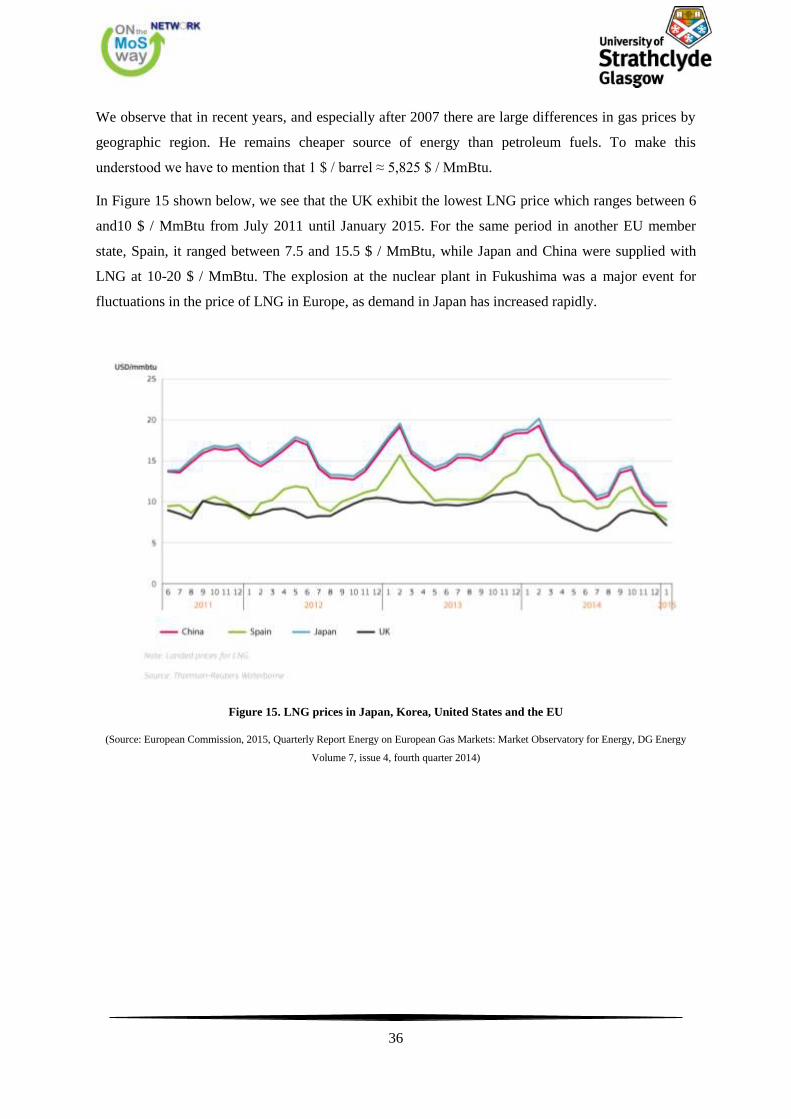
Figure 14. Fuel Prices Gasoline, Gas oil Heavy fuel oil and as presented in Rotterdam. ............. 35
Figure 15. LNG prices in Japan, Korea, United States and the EU ............................................... 36
Figure 16. LNG supply chain as fuel for vessels ............................................................................... 38
Figure17. Natural gas production and consumption from 1989 to 2014 ........................................ 39
Figure18. The main trade routes for gas via pipeline or by LNG carriers .................................... 42
Figure19. Comparison of existing and planned LNG terminals in Norway and UK .................... 43
Figure 20. Existing, planned and under study LNG terminals ....................................................... 44
Figure21. Possible routes for LNG refueling of end users .............................................................. 45
Figure 22. LNG “Bunker vessel” with a 2.800m3 transport capacity. ............................................ 47
Figure 23. LNG Bunker Vessel 6500 cbm ......................................................................................... 48
Figure 24. “Segas” perform/s daily LNG refueling on behalf of the passenger ferry "MS Viking
Grace" .................................................................................................................................................. 56
Figure 25. Seagas Connected to MS Viking Grace .......................................................................... 56
Figure 26. Bunkering Operation at Viking Grace ........................................................................... 57
Figure 27. Dry Disconnect Couplings ............................................................................................... 58
Figure 28. Safe Break Away Coupling 6'' ......................................................................................... 58
7
Figure 29. Design of LNG Bunker Vessel-Bunkering Area ............................................................ 59
Figure 30. LNG Hose Handling ........................................................................................................ 59
Figure 31. LNG Supply from special tankers at dock ..................................................................... 60
Figure 32. Truck to Ship Bunkering Operation ............................................................................... 61
Figure 33. The three main ways to supply ships with LNG fuel ..................................................... 63
Figure 34. A typical LNG supply timeline ........................................................................................ 65
Figure 35. LNG standard Interface for the safe transportion of LNG fuel ................................... 66
Figure36. LNG Facilities at port Haljem, Norway........................................................................... 67
Figure 37. Mitsubishi GS16R-MPTK, source Diesel Power ........................................................... 73
Figure 38. Rolls Royce Bergen C26:33, source: Rolls Royce .......................................................... 73
Figure 39. Wartsila 50DF, source: Wartsila ..................................................................................... 74
Figure 40. Otto cycle ........................................................................................................................... 74
Figure 41. Fuel ratio at various loading conditions ......................................................................... 75
Figure 42. Low pressure fuel injection system ................................................................................. 76
Figure 43. Low pressure fuel injection system ................................................................................. 76
Figure 44. Diesel cycle ......................................................................................................................... 77
Figure 45. Fuel injection system ........................................................................................................ 77
Figure 46. Otto/Miller cycle ............................................................................................................... 79
Figure 47. LNG storage tank ............................................................................................................. 82
Figure 48. Intersection of membrane tank ....................................................................................... 83
Figure 49. Type A tank ...................................................................................................................... 84
Figure 50. LNG tank ........................................................................................................................... 84
Figure 51. LNG tank ........................................................................................................................... 85
Figure 52. LNG Type C Tank ............................................................................................................ 85
Figure 53. LNG tank ........................................................................................................................... 86
Figure 54. LNG double skinned tanks. ............................................................................................. 87
Figure 55. LNG bilobe tank. .............................................................................................................. 87
Figure 56. Gas Combustion Unit ....................................................................................................... 89
Figure 57. LNG tanks location .......................................................................................................... 92
Figure 58. LNG tank in a bulk carrier .............................................................................................. 92
Figure 59. General arrangement drawing in the engine room. ...................................................... 93
Figure 60. Minimum distance LNG tank from the hull .................................................................. 93
Figure 61. Minimum distance of LNG tank from the hull .............................................................. 94
Figure 62. LNG Tanks location limitation- Hazardous zones ......................................................... 95
8
Figure 63. Loading limits for a range of relief valve pressures Source: Maritime Professional . 96
Figure 64. Schematic diagram of fuel gas system with vacuum tank and cold box ...................... 97
Figure 65. Schematic diagram of fuel gas system with compressor ............................................... 98
Figure 66.Schematic diagram of high pressure fuel gas system for two-stroke engines ............... 99
Figure 67. Layout of Dual Fuel engines system of an LNG carrier ............................................... 99
Figure 68. Engine room diagram ..................................................................................................... 100
Figure 69. GVU room by Wartsila. ................................................................................................. 101
Figure 70. M/S Viking Grace ........................................................................................................... 104
Figure 71. Complete system integration – example configuration for Ro-Pax ferry with diesel-
electric propulsion. ............................................................................................................................ 104
Figure 72. M/S Viking Grace-Gas storage and supply systems .................................................... 105
Figure 73. M/S Viking Grace-HVAC-Cold Recovery .................................................................... 106
Figure 74. Cruise ship GA ................................................................................................................ 109
Figure 75. Cruise ship GA ................................................................................................................ 110
Figure 76. GHR Schematic ............................................................................................................... 110
Figure 77. Growth of worldwide passengers carried. .................................................................... 113
Figure 78. Fleet size variation ......................................................................................................... 114
Figure 79. Average age variation .................................................................................................... 114
Figure 80. Elongation concept with prefabricated LNG tanks .................................................... 117
Figure 81. High Level Cost Estimate of Retrofit ............................................................................ 122
Figure 82.Hybrid Scrubber System Costs ...................................................................................... 122
Figure 83. NPV of Cumulative added Cost [Million USD]............................................................ 124
9
List of Tables
Table 1. Current ECA regions ........................................................................................................... 19
Table 2. The investment costs for alternative compliance strategies for retrofitting or new ship
construction ......................................................................................................................................... 31
Table 3. Investment cost for retrofitting or building new ship (in thousand €) ............................ 32
Table 4. Physical and energy properties of fuel types...................................................................... 34
Table 5. Gas volumes consumption, production and imports by EU countries in the year 2011 39
Table 6. Characteristics of the three size scales ............................................................................... 45
Table7. Calibration modes of supply based on the appropriateness for each ship type ............... 68
Table 8. Advantages and disadvantages of the three supply modes ............................................... 69
Table 9. Fuel ratio at various loading conditions ............................................................................. 78
Table 10. Diagram of pollutants for each machine .......................................................................... 80
Table 11. Different Types of LNG Tanks ......................................................................................... 81
10
1. Background
1.1. European Policy for Maritime Transport and Supply Chain
The creation of an effective network of combined transport by integrating land, sea and inland
waterway and air transport has been recognized as an important aspect of sustainable development of
the transport sector in the European Union. For this reason one of the main objectives of EU is the
creation of the Trans-European Transport Networks (TEN-T), (Trans-European Transport network,
TEN-T).
The Commission program TEN-T aims to create interfaces, interoperability and continuity of services
especially for long distance helping to finance the implementation of major transport infrastructure
projects. The development of the Trans-European Transport Network contributes to the smooth
functioning of the internal market and to strengthen economic and social cohesion which has also
been a key element in the renewed Lisbon strategy for competitiveness and employment in Europe
and will play an equally central role in achieving the objectives of the new strategy Europe 2020.
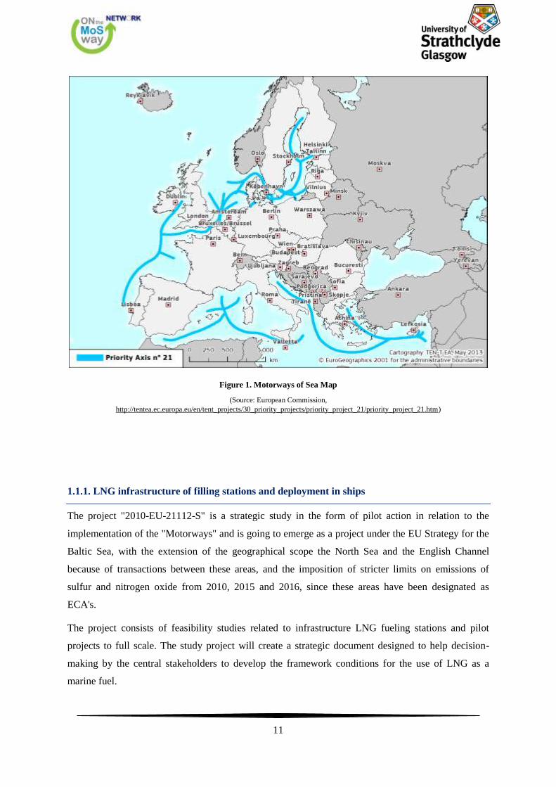
As part of the TEN-T program, Priority Axis No. 21, the concept of "motorways of the sea-
Motorways of the Sea, MoS"1, aims to extend existing and introducing new intermodal maritime
supply chains in Europe. The aim of the "motorways of the sea" is to transfer a significant part of
freight transport from road to sea. To achieve this maritime chains need to be more efficient road
transport and greater sustainability. Successful implementation will help to achieve two main
objectives of European transport policy to reduce road congestion and environmental impact of freight
transport. Also expected to show a marked improvement in access to European markets. For this
purpose, a more comprehensive development of not only maritime transport resources, and
capabilities available to rail and inland waterways as part of an integrated chain. The sea areas
selected to be "Motorways", such as the Baltic, the seas of Southwestern and Southeastern Europe and
sea areas of Western Europe, are presented in Figure 1. The efficiency of the port and its land links
with the hinterland are parameters vital for "Motorways". Three ongoing projects that are part of the
Axis of "Motorways of the Sea" and funded by the EU are "LNG infrastructure of filling stations and
deployment in ships", "LNG in Baltic Sea Ports" and "CO2 & Ship Transport emissions Abatement
through LNG, COSTA" and described below.
1In the White Paper on Transport in September 2001, the European Commission proposed the development of "Motorways"
as part of the TEN-T. The approval on April 29, 2004 Article 12a of the guidelines of TEN-T (gazette TEN-T L 167,
30/04/2004 P.0001-0038, COM (2004) 0884) by the Council and the European Parliament provides the legal framework for
the funding of "Motorways of Sea". (http://ec.europa.eu/transport/modes/maritime/motorways_sea/index_en.htm)
11
Figure 1. Motorways of Sea Map
(Source: European Commission,
http://tentea.ec.europa.eu/en/tent_projects/30_priority_projects/priority_project_21/priority_project_21.htm)
1.1.1. LNG infrastructure of filling stations and deployment in ships
The project "2010-EU-21112-S" is a strategic study in the form of pilot action in relation to the
implementation of the "Motorways" and is going to emerge as a project under the EU Strategy for the
Baltic Sea, with the extension of the geographical scope the North Sea and the English Channel
because of transactions between these areas, and the imposition of stricter limits on emissions of
sulfur and nitrogen oxide from 2010, 2015 and 2016, since these areas have been designated as
ECA's.
The project consists of feasibility studies related to infrastructure LNG fueling stations and pilot
projects to full scale. The study project will create a strategic document designed to help decision-
making by the central stakeholders to develop the framework conditions for the use of LNG as a
marine fuel.
12
It is also expected to endorse a full scale pilot action that aims to highlight the potential of LNG as a
competitive marine. The project aims to bring about positive environmental and climate impacts of
the use of LNG. The purpose of the pilot project full scale is through design modification to build two
new ships that will be able to use propulsion system with fuel LNG. This will be the first time a Ro-
Pax vessel of this size (1350 m lane for trucks) will use LNG.
The full-scale pilot action should include a comprehensive program for performing measurements of
pollutants in order to validate the expected positive environmental and climate impacts from the use
of LNG, as the sulfur content of fuels is zero and combustion emits 90% less NOX than traditional
fuels and corresponding CO2 emissions can be reduced by up to 25%.
The results and experiences drawn from the implementation of the project will have a wider benefit to
other geographical areas within the EU, demonstrating that LNG propulsion is feasible for a large Ro-
Pax vessel and could play important role in the further implementation of LNG in similar vessels
across Europe for short international voyages, as well to domestic traffic.
The project has been completed by 31 December 2011 study on infrastructure related stations for
refueling LNG and recommendations have been vetted by stakeholders. The pilot phase of the project
on the installation and testing of dual fuel engine has been delayed.
1.1.2. LNG in Baltic Sea Ports
The objective of the action "2011-EU-21005-S" is to achieve a harmonized approach to the issue of
infrastructure necessary for the supply of marine fuel LNG shipping in the Baltic Sea. Seven major
ports in four countries and almost all stakeholders and exchange ideas and knowledge in order to
develop a standardized procedure for the design and construction of infrastructure LNG.
The proposed action is based on previous activities and provides for rapid deployment pre-investment
studies to further prepare for investments made in infrastructure ports for refueling LNG. Actual
investment in infrastructure will take place at a later stage.
Additionally, a platform for stakeholders is developed which will gather the key players from the
Baltic Sea and the North Sea in order to ensure the safe distribution of the process and results of the
project. The ports involved in the project will build upon existing knowledge of the field and then
share their experiences and findings. The results of this collaboration will be a key driver, which will
serve as a benchmark for other ports, stakeholders and other regions of Europe.
13
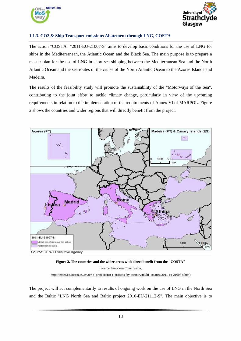
1.1.3. CO2 & Ship Transport emissions Abatement through LNG, COSTA
The action "COSTA" "2011-EU-21007-S" aims to develop basic conditions for the use of LNG for
ships in the Mediterranean, the Atlantic Ocean and the Black Sea. The main purpose is to prepare a
master plan for the use of LNG in short sea shipping between the Mediterranean Sea and the North
Atlantic Ocean and the sea routes of the cruise of the North Atlantic Ocean to the Azores Islands and
Madeira.
The results of the feasibility study will promote the sustainability of the "Motorways of the Sea",
contributing to the joint effort to tackle climate change, particularly in view of the upcoming
requirements in relation to the implementation of the requirements of Annex VI of MARPOL. Figure
2 shows the countries and wider regions that will directly benefit from the project.
Figure 2. The countries and the wider areas with direct benefit from the "COSTA"
(Source: European Commission,
http://tentea.ec.europa.eu/en/ten-t_projects/ten-t_projects_by_country/multi_country/2011-eu-21007-s.htm)
The project will act complementarily to results of ongoing work on the use of LNG in the North Sea
and the Baltic "LNG North Sea and Baltic project 2010-EU-21112-S". The main objective is to
14
increase the capacity of the Motorways of the Sea, by reducing transport costs and reduce emissions
CO2, NOX and SOX, in conjunction with the "greening" of corridors for transport and the use of
LNG as an alternative for shipping fuel. If the policy and recommendations by COSTA are
implemented, it is expected that CO2 emissions from shipping could be reduced by 25% in 2020 and
50% in 2050. As for gaseous pollutants, the use of LNG could eliminate SOX emissions and reduce
NOX by 90%.
1.2. LNG Fuelled Vessels Working Group
Focusing on the use of LNG as a marine fuel, a working group entitled "LNG Fuelled Vessels
Working Group" has been established under the auspices of IAPH's World Ports Climate Initiative
(WPCI) 2
. This Working Group is tasked with work on the development of guidelines regarding safe
bunkering LNG businesses that provide ports around the world. The result is a guide that will provide
information on the implementation of recharging and will be available to any interested party wishes
to pursue this technology.
The port of Antwerp chaired this initiative with representatives from the ports of Amsterdam, Bremen
/ Bremerhaven, Brunsbüttel, Gothenburg, Hamburg, Le Havre, Los Angeles, Long Beach, Rotterdam,
Stockholm and Zeebrugge. The Working Group maintains close ties with the industry organizations
that use and / or operate the LNG today, and governmental organizations.
The Working Group consists of three subgroups:
Checklist for LNG supply
perimeters hazard LNG refueling process
Informing the public about the LNG
The use of LNG as a marine fuel is the reference point in all discussions and research carried out by
all interested members of the shipping industry and government agencies.
1.3. EU project “MARCO POLO” and EIB
EU program "Marco Polo"3 is intended to alleviate congestion and pollution by promoting the shift of
European freight traffic towards greener modes. Railways, shipping routes and inland waterways have
overcapacity. The companies that have viable plans for shifting freight from road to greener transport
2 http://wpci.iaphworldports.org/project-in-progress/WPCI_LNG_Fuelled_Vessels_PressRelease(Mar2013).pdf
3 http://ec.europa.eu/transport/marcopolo/about/index_en.htm
15
modes can approach the program "Marco Polo" to receive financial support. More than 500
companies have already done so successfully since the program began in 2003.
There are five categories of projects eligible for grant under the program "Marco Polo". The main
category of projects designed to immediately turn the mode (switching to other means of transport
such as rail or sea). The other four categories include catalyst actions that promote Motorways of Sea
between major ports, actions to avoid traffic which reduce the transport volumes, and common
learning actions.
Further opportunities for funding are available for the shipping sector through lending from European
Investment Bank (EIB). Shipping finance is an essential part of the core of the overall long-term loans
from EIB. Special attention is given to projects about the shipping industry which contribute to the
development of clean technologies.
1.4. Environmental regulations concerning the Shipping industry
The shipping industry is widely recognized as environmentally and energy efficient, compared to
other transport modes. However, the maritime transport activities continue to affect the environment.
Emissions from ships, such as greenhouse gases (GHG's), ozone precursors and aerosols, nitrogen
oxides (NOx), sulfur oxides (SOx), and volatile organic compounds (VOCs), contribute to air
pollution and climate changes. Particularly emissions SOX and NOX, which are related to the fuel,
are the main causes for the increase in acidity levels of soil and water since they can be easily
converted to active acids. Therefore, the emissions from the shipping industry are an important part of
the global anthropogenic emissions with a contribution in the year 2007 about 15%, 9.4% and 2.7% in
NOX, SO2 and CO2, respectively. It is worth mentioning that between 1990 and 2007, emissions of
key pollutants (NOX, SO2, PM) and greenhouse gases (GHGs) (mainly CO2) emissions from
international shipping have increased from 585 million tons in 1096.
In 2005 emissions NOX, SO2, PM and CO2 from the shipping industry in the Mediterranean were
calculated at 2, 1.45, 0.157 and 87.6 million tons respectively. We must emphasize that the
Mediterranean Sea has been more than 50% of total emissions from ships when compared with other
European seas (within the region EMEP4).
The environmental impact of shipping can be divided into five categories, as dictated by the initiative
of the project "Clean Shipping Project". These categories are:
SOX and PM emissions
4 European Monitoring and Evaluation Programme (EMEP)
16
NOX emissions
CO2 emissions
Waste (solid and liquid waste).
Increased emphasis occurs both globally and locally in relation to environmental issues, coupled with
the growing awareness of the actual burden of pollution from shipping has led to intense development
of regulations at both the international and national level. The introduction at the global level of
emission control area (ECA's) (reference below) is an attempt to address this issue and reduce the
environmental footprint of the maritime industry.
Air pollution in maritime transport are high on the world and European agenda. Agreements and
contracts at the international level and on a regional basis (EU) and many organizations are involved
in shipping differently in different areas. One of the oldest and most important international bodies
governing the shipping industry is the International Maritime Organization (IMO), which is based in
London, UK. IMO is responsible for improving maritime safety, safeguard the environment, maritime
security and the development of international rules that are followed by all shipping nations.
The Convention MARPOL 73/78 of the IMO, is the main International Convention for the Prevention
of Pollution from Ships. Air pollution is regulated in Annex VI "Regulations for the Prevention of Air
Pollution from Ships" (since 2005). More stringent measures adopted by the IMO in relation to SOX
and NOX emissions are introduced with the revised Annex VI to MARPOL.
The EU in the White Paper on Transport has set a target to reduce greenhouse gas emissions at least
40% by 2050 (compared to 2005) in absolute terms for the maritime sector. It also states that the
shipping industry should also contribute to the reduction of local and global emissions. EU legislation
aligned with IMO requirements with Directive 2012/33/EU, which amends Directive 1999/32/EC on
the sulfur content of shipping fuels. The Directive does not contain provisions to regulate ship
emissions for NOx or PM. It also introduces, inter alia, stricter sulfur limits for marine fuels (1.00%
until December 31, 2014 and 0.10% as of 1 January 2015) and in marine areas outside SECAs (3.50%
by June 18, 2014 and initially 0.50% from 1 January 2020 or possibly 20255). In Figure 3 we observe
the sulfur limits with the corresponding periods in both areas SECA's and global level.
5 Depending on the outcome of the review process that will be completed by 2018

17
Figure 3. Regulations imposing sulfur limits and the corresponding deadlines in accordance with Annex VI by
MARPOL
(Source: Lloyd’s Register, 2012, LNG-fuelled deep sea shipping – the outlook for LNG bunker and LNG-fuelled newbuild demand up to
2025)
Apart from the new regulations IMO's sulfur emissions, there are many other programs concerning
reductions of the environmental footprint of the maritime industry. Some of them are listed below.
Energy Efficiency Design Index (EEDI), is an international directive regulating energy efficiency
(new ships) 6
Management Plan of the Energy Performance History (SEEMP), is an international directive on
energy efficiency (all ships)
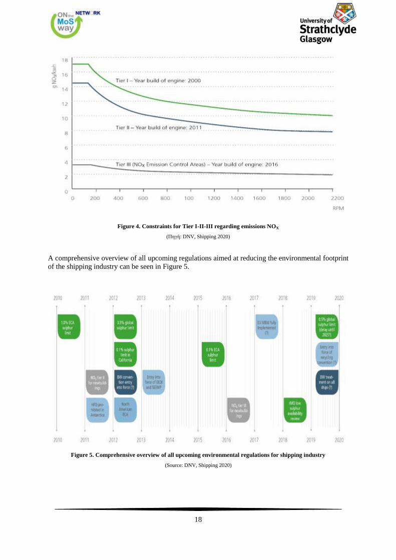
Rules of Tier I, Tier II and Tier III for NOX emissions from ship engines, as we can see in Figure
4.
6 The first official rules for CO2 were adopted by IMO in 2011. These include Energy Performance Index
(EEDI) and the Management Plan of the Energy Performance History (SEEMP).
18
Figure 4. Constraints for Tier I-II-III regarding emissions NOX
(Πηγή: DNV, Shipping 2020)
A comprehensive overview of all upcoming regulations aimed at reducing the environmental footprint
of the shipping industry can be seen in Figure 5.
Figure 5. Comprehensive overview of all upcoming environmental regulations for shipping industry
(Source: DNV, Shipping 2020)
19
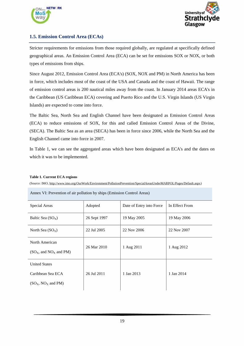
1.5. Emission Control Area (ECAs)
Stricter requirements for emissions from those required globally, are regulated at specifically defined
geographical areas. An Emission Control Area (ECA) can be set for emissions SOX or NOX, or both
types of emissions from ships.
Since August 2012, Emission Control Area (ECA's) (SOX, NOX and PM) in North America has been
in force, which includes most of the coast of the USA and Canada and the coast of Hawaii. The range
of emission control areas is 200 nautical miles away from the coast. In January 2014 areas ECA's in
the Caribbean (US Caribbean ECA) covering and Puerto Rico and the U.S. Virgin Islands (US Virgin
Islands) are expected to come into force.
The Baltic Sea, North Sea and English Channel have been designated as Emission Control Areas
(ECA) to reduce emissions of SOX, for this and called Emission Control Areas of the Divine,
(SECA). The Baltic Sea as an area (SECA) has been in force since 2006, while the North Sea and the
English Channel came into force in 2007.
In Table 1, we can see the aggregated areas which have been designated as ECA's and the dates on
which it was to be implemented.
Table 1. Current ECA regions
(Source: IMO, http://www.imo.org/OurWork/Environment/PollutionPrevention/SpecialAreasUnderMARPOL/Pages/Default.aspx)
Annex VI: Prevention of air pollution by ships (Emission Control Areas)
Special Areas Adopted Date of Entry into Force In Effect From
Baltic Sea (SOX) 26 Sept 1997 19 May 2005 19 May 2006
North Sea (SOX) 22 Jul 2005 22 Nov 2006 22 Nov 2007
North American
(SOX, and NOX and PM)
26 Mar 2010 1 Aug 2011 1 Aug 2012
United States
Caribbean Sea ECA
(SOX, NOX and PM)
26 Jul 2011 1 Jan 2013 1 Jan 2014

20
The largest European sea that has not been designated as a SECA region is the Mediterranean. The
expected increase in traffic in the Mediterranean and the resulting increase in air emissions from ships
makes it an ideal candidate to put under SECA regulations. The program SAFEMED funded by the
European Union, deals with the preparations needed for the application to the IMO with a view to the
Mediterranean region designated as SECA. Figure 6 presents the existing and candidate ECA regions.
Figure 6. Existing and possible future ECA areas
(Source: DNV, http://blogs.dnv.com/lng/2011/02/lng-for-greener-shipping-in-north-america/)
21
2. Shipping industry overview
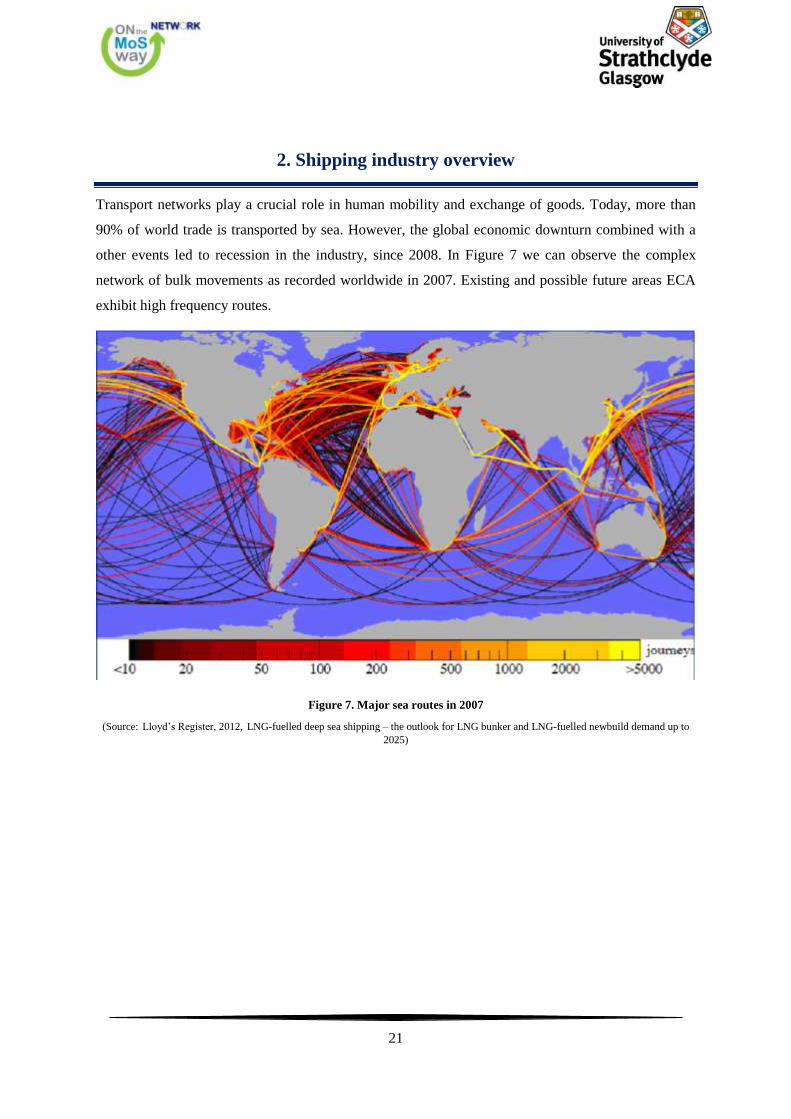
Transport networks play a crucial role in human mobility and exchange of goods. Today, more than
90% of world trade is transported by sea. However, the global economic downturn combined with a
other events led to recession in the industry, since 2008. In Figure 7 we can observe the complex
network of bulk movements as recorded worldwide in 2007. Existing and possible future areas ECA
exhibit high frequency routes.
Figure 7. Major sea routes in 2007
(Source: Lloyd’s Register, 2012, LNG-fuelled deep sea shipping – the outlook for LNG bunker and LNG-fuelled newbuild demand up to
2025)
22
2.1. Shipping industry and European Seas
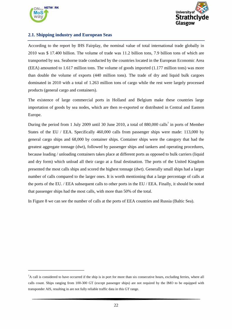
According to the report by IHS Fairplay, the nominal value of total international trade globally in
2010 was $ 17.400 billion. The volume of trade was 11.2 billion tons, 7.9 billion tons of which are
transported by sea. Seaborne trade conducted by the countries located in the European Economic Area
(EEA) amounted to 1.617 million tons. The volume of goods imported (1.177 million tons) was more
than double the volume of exports (440 million tons). The trade of dry and liquid bulk cargoes
dominated in 2010 with a total of 1.263 million tons of cargo while the rest were largely processed
products (general cargo and containers).
The existence of large commercial ports in Holland and Belgium make these countries large
importation of goods by sea nodes, which are then re-exported or distributed in Central and Eastern
Europe.
During the period from 1 July 2009 until 30 June 2010, a total of 880,000 calls7 in ports of Member
States of the EU / EEA. Specifically 460,000 calls from passenger ships were made: 113,000 by
general cargo ships and 68,000 by container ships. Container ships were the category that had the
greatest aggregate tonnage (dwt), followed by passenger ships and tankers and operating procedures,
because loading / unloading containers takes place at different ports as opposed to bulk carriers (liquid
and dry form) which unload all their cargo at a final destination. The ports of the United Kingdom
presented the most calls ships and scored the highest tonnage (dwt). Generally small ships had a larger
number of calls compared to the larger ones. It is worth mentioning that a large percentage of calls at
the ports of the EU. / EEA subsequent calls to other ports in the EU / EEA. Finally, it should be noted
that passenger ships had the most calls, with more than 50% of the total.
In Figure 8 we can see the number of calls at the ports of EEA countries and Russia (Baltic Sea).
7A call is considered to have occurred if the ship is in port for more than six consecutive hours, excluding ferries, where all
calls count. Ships ranging from 100-300 GT (except passenger ships) are not required by the IMO to be equipped with
transponder AIS, resulting in are not fully reliable traffic data in this GT range.
23
Figure 8. The number of total calls of ships to the ports of the EEA and Russia (Baltic Sea)
(Source: IHS Fairplay, 2011, Ships Visiting European Ports)
The average time length for ships within the control area of the port (except anchors) was 35 hours.
Obviously this varies significantly between ship types. For example, container ships remain in the
control area of the port for a shorter time than general cargo ships. Also, it is absolutely clear that
there are large differences between ports in different countries for the same type of vessel (35 hours in
Bulgaria and 27 hours in Greece and the Netherlands).
The average age of the ships was 15 years. Tankers visiting ports within EEA than the average for the
world fleet of this category while drybulk vessel ages are quite larger.
What is more, we can see an overview of the maritime industry in the ports of the countries of the EU.
/ EEA countries located in the Baltic Sea, North Sea and Irish, Western and Eastern Mediterranean.
We observe that most calls were made at the port of North and Irish Sea while fewer in the Eastern
Mediterranean.
North and Irish Sea a total of 431,000 calls, of which 204,000 from passenger ships, tankers from
57,000 to 36,000 by container vessels. On average, the ships remained in the control area of the port
34 hours and had an average age of 14 years.
In the Baltic Sea, a total of 187,000 calls, of which 111,000 by passenger ships, 17,000 by tankers and
8,000 by container ships. On average, the ships remained in the control area of the port 32 hours and
had a median age of 17 years.
24
West Mediterranean had a total of 211,000 calls, of which 120,000 by passenger cars, 21,000 by
tankers and 21,000 by container ships. On average, the ships remained in the control area of the port
36 hours and had an average age of 16 years.
In the Eastern Mediterranean a total of 52,000 calls were made, of which 24,000 by passenger cars, by
9,000 tankers and 3,000 by container ships. On average, the ships remained in the control area of the
port 55 hours and had a median age of 21 years.
2.2. Shipping industry in the Mediterranean Sea
The Mediterranean is a vital sea route connecting traffic between oceans. It borders with 22 countries
and is a synthesis of unique marine biodiversity. There are 480 ports and terminals where 50% of ship
took place in Greece and Italy. Moreover, about 20% of Mediterranean ports are located in the eastern
Mediterranean east of Greece, while the remaining 80% in Western and Central Mediterranean.
According to the study presented in the program SAFEMED 2008, the Mediterranean Sea is the
busiest international water region and represents almost 15% of global shipping activity based on the
number of calls made in 2006. More than 13,000 ships over 100 GT have made 252,000 calls to ports
and represent 3.8 billion tons capacity. Still, it is an important passage with about 10,000 transits by
vessels in ports outside the Mediterranean. The size of ships crossing the Mediterranean is on average
50.000 dwt, at least three times larger than the vessels serving the trade in the Mediterranean.
In general, vessels serving trade within the Mediterranean are older ships and small capacity, such as
mini-and handymax bulkers. Ships with the highest average age presented mainly in the Eastern
Mediterranean.
Trade in coastal states bordering the Mediterranean constitutes 19% of world seaborne trade volume
in 2006, while it reached a total of 7.5 billion tons. Also the same year, the sea trade between the
Mediterranean coastal states, which are relatively underdeveloped, representing 18% of all the
Mediterranean coastal commercial activities, totally amounted to 1.4 billion tons. Small ships
operating in the Mediterranean dominate the frequency calls, while large-volume concentrated in a
few terminals.
The trade of crude oil and LNG are very important as they represent about 60% of all sea transport
between coastal States of the Mediterranean. Large numbers of crude oil carriers that cross the
Mediterranean, mainly through the Suez Canal to Gibraltar or from the Black Sea ports to destinations
in the Mediterranean. In Figure 9 (a) and (b), we can see the sea routes of crude oil in the major
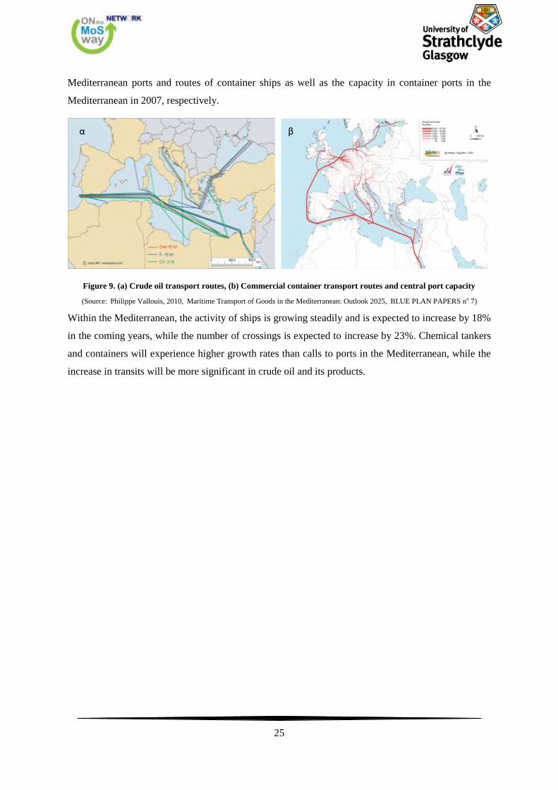
25
Mediterranean ports and routes of container ships as well as the capacity in container ports in the
Mediterranean in 2007, respectively.
Figure 9. (a) Crude oil transport routes, (b) Commercial container transport routes and central port capacity
(Source: Philippe Vallouis, 2010, Maritime Transport of Goods in the Mediterranean: Outlook 2025, BLUE PLAN PAPERS no 7)
Within the Mediterranean, the activity of ships is growing steadily and is expected to increase by 18%
in the coming years, while the number of crossings is expected to increase by 23%. Chemical tankers
and containers will experience higher growth rates than calls to ports in the Mediterranean, while the
increase in transits will be more significant in crude oil and its products.
α β
26
3. Compliance Strategies of Owners with the Regulations
There are two realistic alternatives other than the use of LNG, to meet the requirements of the new
regulations in the short and medium term. The first is the ships continue to use heavy fuel (Heavy
Fuel Oil, HFO) but with the addition of the FGD (Scrubber) to reduce sulfur emissions and the second
is the use of fuel with low sulfur content type Marine Gas Oil (MGO). All alternatives result in the
imposition of major expenses for owners and their businesses.
Final decision depends on various economic aspects such as investment and operating costs as well as
how to set fuel prices in the future which is the most important of all.
3.1. Scrubber
Abatement technologies or “end-of-pipe” solutions, mainly include the use of "scrubber" to remove
SOX and PM in combination with either selective catalytic reduction system (Selective Catalytic
Reduction, SCR) or exhaust gas recirculation (Exhaust Gas Recirculation, EGR) for reducing NOX
emissions. This combination is considered to have good prospects for fulfilling the requirements in
the areas 2015 SECA and Tier III ECA areas requirements. It is likely that Tier III NOX requirements
can be met even without the application of the SCR technique.
The main advantage of the "scrubber" technology is that it can be used for fuels with high sulfur
content that is readily available, i.e. HFO, thus keeping fuel costs low and for which there is, at
present, effective network infrastructure providing that fuel type. The use of HFO does not require
ship owners to upgrade or replace their machines. Tests carried out by adding "scrubber" show that
sulfur emissions are reduced almost to zero and also achieved a significant reduction in PM.
Besides the necessary capital investment in equipment, "scrubber" onboard waste generated from the
operation will be managed and disposed of in the harbor. At present, there is no infrastructure in ports
for the reception and disposal of this waste type, while there are also no regulations that dictate the
responsibilities of the port about the management of such waste. In July 2011, the IMO adopted a
resolution giving guidelines for disposal facilities under Annex VI to MARPOL. A charging system
receiving the waste must be designed not to create disincentives to unsafe delivery ashore due to
undue delay or cost.
Other disadvantages using "scrubber" is that the proportion of CO2 in the exhaust gas is not reduced,
and that any "scrubber" used to meet the SECA requirements must be certified by the IMO. Also, the
use of technology "scrubber" occupies enough space and in some cases the load capacity must be
reduced. For compliance strategy using "scrubber", the existence of high availability of the equipment
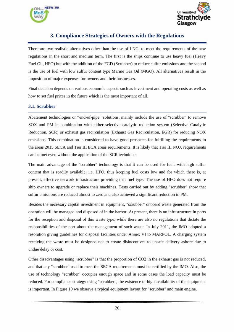
is important. In Figure 10 we observe a typical equipment layout for "scrubber" and main engine.
27
Figure 10. A typical design of "dry SOX scrubber system". The physical dimensions is in relation to the main engine.
(Source: Lloyd’s Register, 2012, Understanding exhaust gas treatment systems)
28
3.2. MGO fuel type
Conventional marine fuels used by commercial vessels are usually divided into two categories,
distillation residues and fractional distillation products. The fuel derived from distillation residues,
often referred to as heavy fuel oil (HFO), are heavier marine fuels compared with the viscosity and
sulfur content. The distillate fuels can be divided into two categories, fuel type Marine Gas Oil
(MGO) and Marine Diesel Oil (MDO). When the fuel is derived from the distillation residue mixed
with fuel by fractional distillation, the mixture is called intermediate fuel (IFO).
Theoretically, it is possible to proceed with desulphurisation of HFO fuel and produce HFO of sulfur
0.1% content, but in practice the most viable option when choosing an alternative fuel oil to comply
with SECA regulations, is to use MGO fuel. If refineries have a surplus of HFO, it is likely to
produce, through processes such as pyrolysis, etc., MGO.
The MGO with 0.1% sulfur content or less are readily available and has similar properties as diesel
fuel used for high-speed diesel engines. The viscosity of MGO is lower than that of MDO or HFO for
operation in two-stroke marine diesel engines, but the fuel may need to be cooled in order to remain at
certain levels of viscosity according to the design of the engine, to prevent damage of fuel pumps and
other equipment. The viscosity should not be lower than 2cSt and it is recommended to be above 3cSt.
The alternation of preheated HFO (80-150oC) in cooled MGO (max 35 ° C) during the entrance into
SECA regions should be executed with due attention to the actual viscosity fuels, particularly in
conventional engines without injection systems common collector (Common Rail Systems). For long-
term use of MGO, it may also be necessary to change the lubricating oil with another oil quality.
With MGO achieve emission reductions SOX and PM. NOX emissions and greenhouse gases remain
at the same level as during the use of HFO. In order to comply with emissions NOx Tier III, SCR and
EGR systems are necessary. An advantage of using MGO is not requiring modification of the motor
and the extra volume for storage tanks, which makes investing quite small or even zero. However, the
price for the fuel MGO is significantly higher than for HFO and generally believed to increase to
some extent because of limited refining capacity.
3.3. LNG
The engines using LNG as fuel have proven to be a reliable solution as well as the LNG is an
environmentally friendly fuel with low sulfur content. The exhaust emissions, such as SOX and PM
using LNG are negligible. The NOX emissions can be reduced by about 80-90% for four-stroke Otto
and 10-20% for two-stroke engines. Still LNG contains less carbon than the other fuels, reducing CO2
emissions by approximately 20%. In Figure 11 we can see the significant environmental advantages
of the LNG fuel compared to other alternatives.
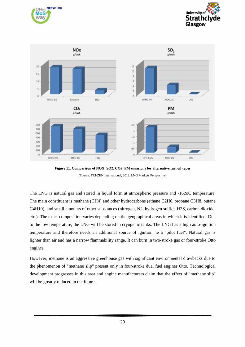
29
Figure 11. Comparison of NOX, SO2, CO2, PM emissions for alternative fuel oil types
(Source: TRI-ZEN International, 2012, LNG Markets Perspective)
The LNG is natural gas and stored in liquid form at atmospheric pressure and -162oC temperature.
The main constituent is methane (CH4) and other hydrocarbons (ethane C2H6, propane C3H8, butane
C4H10), and small amounts of other substances (nitrogen, N2, hydrogen sulfide H2S, carbon dioxide,
etc.). The exact composition varies depending on the geographical areas in which it is identified. Due
to the low temperature, the LNG will be stored in cryogenic tanks. The LNG has a high auto-ignition
temperature and therefore needs an additional source of ignition, ie a "pilot fuel". Natural gas is
lighter than air and has a narrow flammability range. It can burn in two-stroke gas or four-stroke Otto
engines.
However, methane is an aggressive greenhouse gas with significant environmental drawbacks due to
the phenomenon of "methane slip" present only in four-stroke dual fuel engines Otto. Technological
development progresses in this area and engine manufacturers claim that the effect of "methane slip"
will be greatly reduced in the future.
30
According to the final Working Paper of the European Commission, SWD (2013) 8,, the use of LNG
as a marine fuel is the most promising alternative for both the short and medium term, at least for
short sea shipping and sea- activities other than transport, eg fishing and offshore services.
3.3.1. LNG engine choices
Otto
LNG may be used as fuel, when the ship is operating in SECA areas and simple oil can be used
outside SECA and in areas where fuel gas is not available. The operating principle is based on the use
of LNG Otto cycle and Diesel cycle is the basis for the operation of a fuel oil. The ignition source
during operation LNG is a small amount of oil, "pilot fuel", which is injected and ignited by the heat
generated by the compression and combustion.
Diesel
The technology of this engine implements gas injected at high pressure (about 300 bar) with "pilot
fuel". This machine can only use fuel oil or a mixture of gas and oil.
Single fuel gas engines
The cycle Otto / Miller is the basis for the operation of this engine. Instead of a pilot fuel, a rich gas /
air mixture is ignited in a combustion antechamber, which forms a strong ignition source for the very
poor mixture in the cylinder. This technology ensures high efficiency and low emissions, but does not
allow flexibility of oil use.
3.4. Investment and operational costs for alternative fuel solutions
Continued use of HFO in conjunction with the installation "scrubber" is associated with a significant
investment cost for acquiring the "scrubber" and related equipment. However, operating costs are
marginally affected due to slight increase in fuel. It should be noted that there is difference in
investment costs between retrofitting an existing vessel (retrofit installations) and construction of a
new ship.
The solution of the rotation function from HFO to MGO has led to a considerable increase in
operating costs, essentially in proportion to the price difference between HFO and MGO. Major
changes or investment costs for the ship is not necessarily in this solution. A key advantage is that
existing infrastructure supply fuel oil have the ability to offer their customers MGO without
undergoing dramatic changes.
8 Actions towards a comprehensive EU framework on LNG for shipping
31
For the use of LNG in existing ships, substantial reconstruction works including diesel engines and
LNG tanks are required. The newbuilding are themselves associated with high costs if they are
equipped with dual fuel engine or only with LNG and fuel tanks. However the most important factor
for the economic viability of the use of LNG as fuel for ships is the price of LNG for the owner of the
ship (FOB).
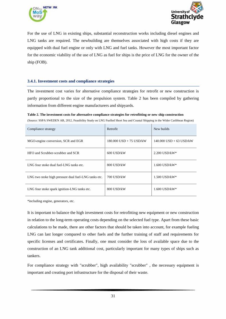
3.4.1. Investment costs and compliance strategies
The investment cost varies for alternative compliance strategies for retrofit or new construction is
partly proportional to the size of the propulsion system. Table 2 has been compiled by gathering
information from different engine manufacturers and shipyards.
Table 2. The investment costs for alternative compliance strategies for retrofitting or new ship construction
(Source: SSPA SWEDEN AB, 2012, Feasibility Study on LNG Fuelled Short Sea and Coastal Shipping in the Wider Caribbean Region)
Compliance strategy Retrofit New builds
MGO-engine conversion, SCR and EGR 180.000 USD + 75 USD/kW 140.000 USD + 63 USD/kW
HFO and Scrubber-scrubber and SCR 600 USD/kW 2.200 USD/kW*
LNG four stoke dual fuel-LNG tanks etc. 800 USD/kW 1.600 USD/kW*
LNG two stoke high pressure dual fuel-LNG tanks etc. 700 USD/kW 1.500 USD/kW*
LNG four stoke spark ignition-LNG tanks etc. 800 USD/kW 1.600 USD/kW*
*including engine, generators, etc.
It is important to balance the high investment costs for retrofitting new equipment or new construction
in relation to the long-term operating costs depending on the selected fuel type. Apart from these basic
calculations to be made, there are other factors that should be taken into account, for example fueling
LNG can last longer compared to other fuels and the further training of staff and requirements for
specific licenses and certificates. Finally, one must consider the loss of available space due to the
construction of an LNG tank additional cost, particularly important for many types of ships such as
tankers.
For compliance strategy with "scrubber", high availability "scrubber" , the necessary equipment is
important and creating port infrastructure for the disposal of their waste.
32
The alternative solution of using MGO is considered to be quite attractive as it is a strategy with low
investment costs for those who believe that LNG can be a breakthrough sometime in the mid-term
future. However, if the ships that follow this strategy increase the direct result is increased demand for
MGO, and therefore its value can be further increased.
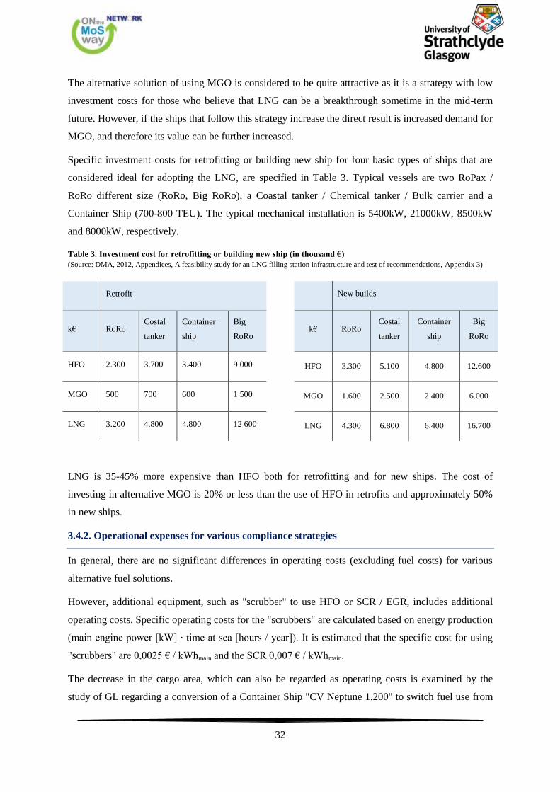
Specific investment costs for retrofitting or building new ship for four basic types of ships that are
considered ideal for adopting the LNG, are specified in Table 3. Typical vessels are two RoPax /
RoRo different size (RoRo, Big RoRo), a Coastal tanker / Chemical tanker / Bulk carrier and a
Container Ship (700-800 TEU). The typical mechanical installation is 5400kW, 21000kW, 8500kW
and 8000kW, respectively.
Table 3. Investment cost for retrofitting or building new ship (in thousand €)
(Source: DMA, 2012, Appendices, A feasibility study for an LNG filling station infrastructure and test of recommendations, Appendix 3)
New builds
k€ RoRo Costal
tanker
Container
ship
Big
RoRo
HFO 3.300 5.100 4.800 12.600
MGO 1.600 2.500 2.400 6.000
LNG 4.300 6.800 6.400 16.700
LNG is 35-45% more expensive than HFO both for retrofitting and for new ships. The cost of
investing in alternative MGO is 20% or less than the use of HFO in retrofits and approximately 50%
in new ships.
3.4.2. Operational expenses for various compliance strategies
In general, there are no significant differences in operating costs (excluding fuel costs) for various
alternative fuel solutions.
However, additional equipment, such as "scrubber" to use HFO or SCR / EGR, includes additional
operating costs. Specific operating costs for the "scrubbers" are calculated based on energy production
(main engine power [kW] ∙ time at sea [hours / year]). It is estimated that the specific cost for using
"scrubbers" are 0,0025 € / kWhmain and the SCR 0,007 € / kWhmain.
The decrease in the cargo area, which can also be regarded as operating costs is examined by the
study of GL regarding a conversion of a Container Ship "CV Neptune 1.200" to switch fuel use from
Retrofit
k€ RoRo Costal
tanker
Container
ship
Big
RoRo
HFO 2.300 3.700 3.400 9 000
MGO 500 700 600 1 500
LNG 3.200 4.800 4.800 12 600

33
HFO to LNG. Due to the size of the required tanks LNG, the capacity of 1.284 TEU decreased by 48
TEU in 1.236 TEU (4% decrease). In container ships the cargo space lost is of great importance,
which in other types of ships has no particular interest as it may be easier to place LNG tank in an
area that will not affect the capacity. This may be better understood by the first sea-going tanker "Bit
Viking" which was retrofitted for use fuel LNG. Fuel tanks 500 m3 placed on deck as observed in
Figure 12, did not really lead to any reduction in load carrying capacity. However, special
requirements must be met for both storage tanks and for the fuel system due to the specificities of the
LNG.
Figure 12. M/T Bit Viking
(Source: GL, http://www.gl-group.com/assets/img/gl_conducts_clean_shipping_index_verification_for_bit_viking.jpg)
Maintenance costs, staffing, training, and indirect costs are more or less similar for all types of fuel
and therefore do not affect the competitiveness of alternatives.
The most important parameter for operating costs is the prices of different types of fuel with which we
will deal in more detail in the next chapter. We should note that calorific value and density, two key
characteristics of fuels, vary between the different grades of petroleum fuels and depend on the
specific composition of LNG. Therefore, it is important to consider these differences when the price
comparisons are made for different fuel types and costs of any compliance strategy. For comparisons
of values listed in the following section, the sizes below in Table 4 in SI units are considered
representative.

34
Table 4. Physical and energy properties of fuel types
(Source: SSPA SWEDEN AB, 2012, Feasibility Study on LNG Fuelled Short Sea and Coastal Shipping in the Wider Caribbean Region)
Fuel Density (kg/m3) Specific Energy (GJ/tonne)
MGO 850 46
HFO 990 43
LNG 450 54
3.5. Expenditure on LNG supplies and competitive fuel types
The shipping industry is one of the main consumers of fossil fuels. HFO was for many years the
choice of shipowners as shipping fuel but in recent decades, the pressures from the international
community to reduce the environmental footprint of ships has led owners to seek alternative forms of
energy and / or new technologies. Even the strict limits for the pollutants of the shipping industry
were to be implemented in the coming years this subject is of paramount importance for companies.
Compliance strategy heavily depends on fuel prices, as fuel oil costs can represent between 50% and
70% of the total cost of ownership and operation of a ship. This means that any changes in these
values during the life cycle of the ship overshadow all other considerations in the management of the
ship. Fuel price forecast is not an objective of the study. However, below we briefly describe the
market for these types of fuels.
3.5.1. Historical Prices and price relationships of HFO, LNG and MGO
Fuel prices vary greatly depending on the geographical areas in which they are delivered. Petroleum
products are inextricably linked to the crude oil market. The last decade and particularly since the
middle of 2003 a significant increase in prices of petroleum products took place. In Figure 13 we can
see the prices for Gasoline, Gas oil, and heavy fuel oil in Rotterdam from 1997 until 2014.
35
Figure 13. Gasoline, Gas oil and Heavy fuel oil prices in Rotterdam.
(Source: BP, 2015, Statistical Review of World Energy)
Figure 14. Fuel Prices Gasoline, Gas oil Heavy fuel oil and as presented in Rotterdam.
(Source: BP, 2015, Statistical Review of World Energy)
36
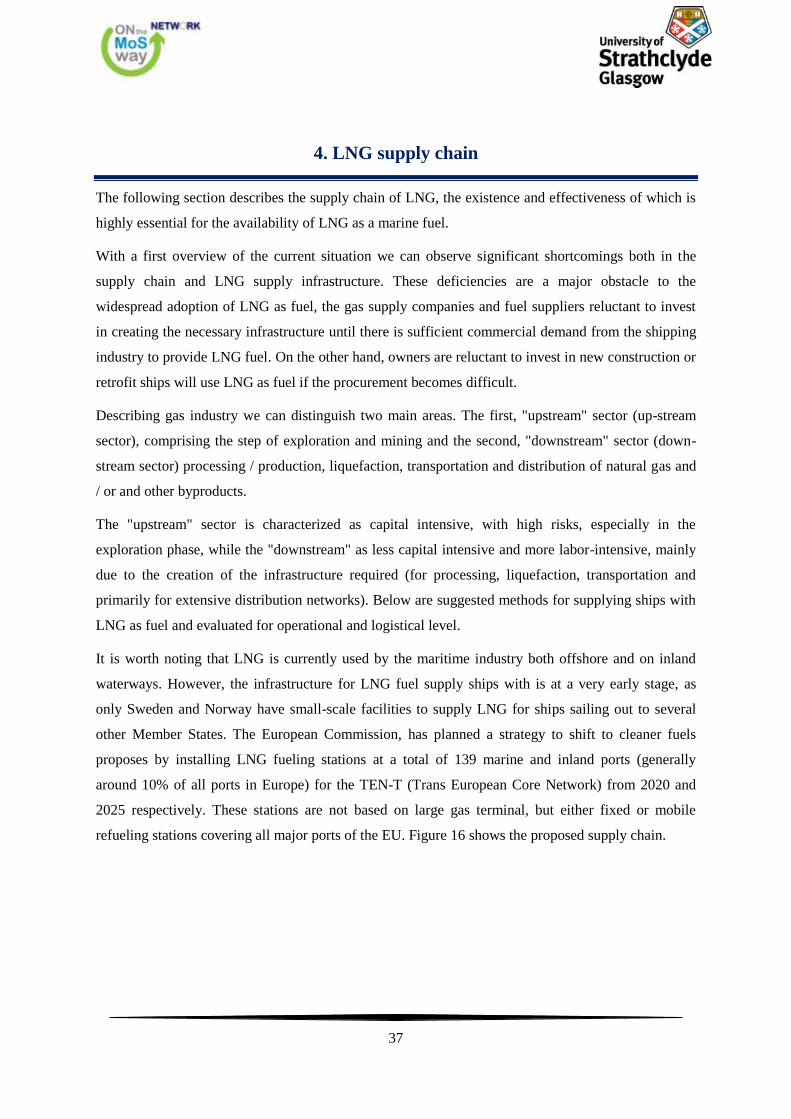
We observe that in recent years, and especially after 2007 there are large differences in gas prices by
geographic region. He remains cheaper source of energy than petroleum fuels. To make this
understood we have to mention that 1 $ / barrel ≈ 5,825 $ / MmBtu.
In Figure 15 shown below, we see that the UK exhibit the lowest LNG price which ranges between 6
and10 $ / MmBtu from July 2011 until January 2015. For the same period in another EU member
state, Spain, it ranged between 7.5 and 15.5 $ / MmBtu, while Japan and China were supplied with
LNG at 10-20 $ / MmBtu. The explosion at the nuclear plant in Fukushima was a major event for
fluctuations in the price of LNG in Europe, as demand in Japan has increased rapidly.
Figure 15. LNG prices in Japan, Korea, United States and the EU
(Source: European Commission, 2015, Quarterly Report Energy on European Gas Markets: Market Observatory for Energy, DG Energy
Volume 7, issue 4, fourth quarter 2014)
37
4. LNG supply chain
The following section describes the supply chain of LNG, the existence and effectiveness of which is
highly essential for the availability of LNG as a marine fuel.
With a first overview of the current situation we can observe significant shortcomings both in the
supply chain and LNG supply infrastructure. These deficiencies are a major obstacle to the
widespread adoption of LNG as fuel, the gas supply companies and fuel suppliers reluctant to invest
in creating the necessary infrastructure until there is sufficient commercial demand from the shipping
industry to provide LNG fuel. On the other hand, owners are reluctant to invest in new construction or
retrofit ships will use LNG as fuel if the procurement becomes difficult.
Describing gas industry we can distinguish two main areas. The first, "upstream" sector (up-stream
sector), comprising the step of exploration and mining and the second, "downstream" sector (down-
stream sector) processing / production, liquefaction, transportation and distribution of natural gas and
/ or and other byproducts.
The "upstream" sector is characterized as capital intensive, with high risks, especially in the
exploration phase, while the "downstream" as less capital intensive and more labor-intensive, mainly
due to the creation of the infrastructure required (for processing, liquefaction, transportation and
primarily for extensive distribution networks). Below are suggested methods for supplying ships with
LNG as fuel and evaluated for operational and logistical level.
It is worth noting that LNG is currently used by the maritime industry both offshore and on inland
waterways. However, the infrastructure for LNG fuel supply ships with is at a very early stage, as
only Sweden and Norway have small-scale facilities to supply LNG for ships sailing out to several
other Member States. The European Commission, has planned a strategy to shift to cleaner fuels
proposes by installing LNG fueling stations at a total of 139 marine and inland ports (generally
around 10% of all ports in Europe) for the TEN-T (Trans European Core Network) from 2020 and
2025 respectively. These stations are not based on large gas terminal, but either fixed or mobile
refueling stations covering all major ports of the EU. Figure 16 shows the proposed supply chain.
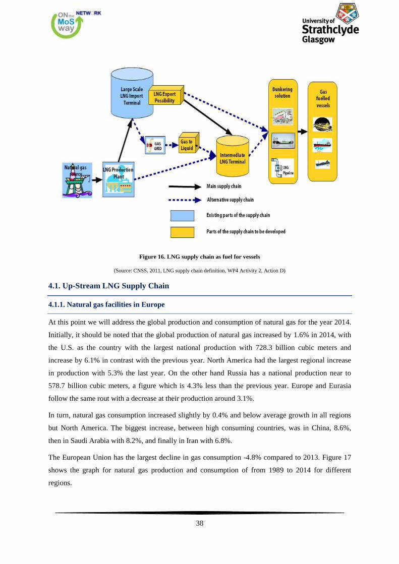
38
Figure 16. LNG supply chain as fuel for vessels
(Source: CNSS, 2011, LNG supply chain definition, WP4 Activity 2, Action D)
4.1. Up-Stream LNG Supply Chain
4.1.1. Natural gas facilities in Europe
At this point we will address the global production and consumption of natural gas for the year 2014.
Initially, it should be noted that the global production of natural gas increased by 1.6% in 2014, with
the U.S. as the country with the largest national production with 728.3 billion cubic meters and
increase by 6.1% in contrast with the previous year. North America had the largest regional increase
in production with 5.3% the last year. On the other hand Russia has a national production near to
578.7 billion cubic meters, a figure which is 4.3% less than the previous year. Europe and Eurasia
follow the same rout with a decrease at their production around 3.1%.
In turn, natural gas consumption increased slightly by 0.4% and below average growth in all regions
but North America. The biggest increase, between high consuming countries, was in China, 8.6%,
then in Saudi Arabia with 8.2%, and finally in Iran with 6.8%.
The European Union has the largest decline in gas consumption -4.8% compared to 2013. Figure 17
shows the graph for natural gas production and consumption of from 1989 to 2014 for different
regions.
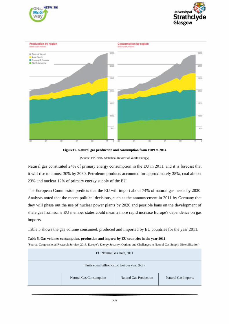
39
Figure17. Natural gas production and consumption from 1989 to 2014
(Source: BP, 2015, Statistical Review of World Energy)
Natural gas constituted 24% of primary energy consumption in the EU in 2011, and it is forecast that
it will rise to almost 30% by 2030. Petroleum products accounted for approximately 38%, coal almost
23% and nuclear 12% of primary energy supply of the EU.
The European Commission predicts that the EU will import about 74% of natural gas needs by 2030.
Analysts noted that the recent political decisions, such as the announcement in 2011 by Germany that
they will phase out the use of nuclear power plants by 2020 and possible bans on the development of
shale gas from some EU member states could mean a more rapid increase Europe's dependence on gas
imports.
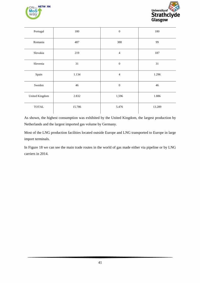
Table 5 shows the gas volume consumed, produced and imported by EU countries for the year 2011.
Table 5. Gas volumes consumption, production and imports by EU countries in the year 2011
(Source: Congressional Research Service, 2013, Europe’s Energy Security: Options and Challenges to Natural Gas Supply Diversification)
EU Natural Gas Data, 2011
Units equal billion cubic feet per year (bcf)
Natural Gas Consumption Natural Gas Production Natural Gas Imports

40
Austria 335 58 339
Belgium 569 0 802
Bulgaria 102 0 101
Cyprus 0 0 0
Czech Republic 297 7 424
Denmark 148 251 0
Estonia 13 0 13
Finland 127 0 134
France 1.423 26 1.141
Germany 2.560 353 2.966
Greece 159 0 117
Hungary 360 88 237
Ireland 166 11 191
Italy 2.518 271 2.147
Latvia 23 0 23
Lithuania 120 0 120
Luxembourg 48 0 48
Malta 0 0 0
Netherlands 1.345 2.267 480
Poland 544 152 381
41
Portugal 180 0 180
Romania 487 388 99
Slovakia 219 4 187
Slovenia 31 0 31
Spain 1.134 4 1.296
Sweden 46 0 46
United Kingdom 2.832 1,596 1.886
TOTAL 15.786 5.476 13.289
As shown, the highest consumption was exhibited by the United Kingdom, the largest production by
Netherlands and the largest imported gas volume by Germany.
Most of the LNG production facilities located outside Europe and LNG transported to Europe in large
import terminals.
In Figure 18 we can see the main trade routes in the world of gas made either via pipeline or by LNG
carriers in 2014.
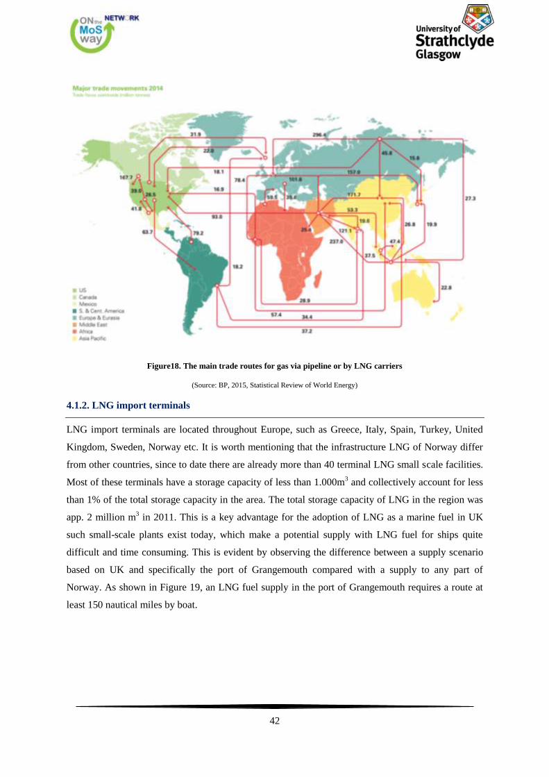
42
Figure18. The main trade routes for gas via pipeline or by LNG carriers
(Source: BP, 2015, Statistical Review of World Energy)
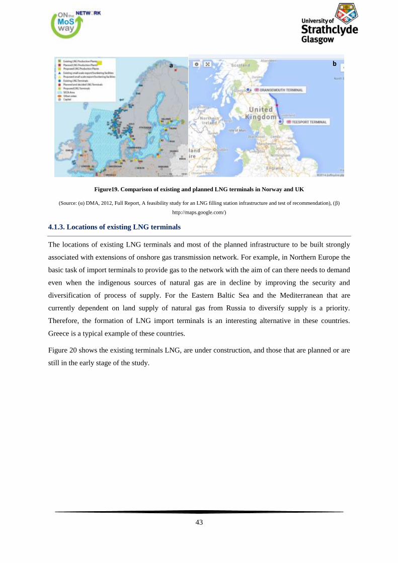
4.1.2. LNG import terminals
LNG import terminals are located throughout Europe, such as Greece, Italy, Spain, Turkey, United
Kingdom, Sweden, Norway etc. It is worth mentioning that the infrastructure LNG of Norway differ
from other countries, since to date there are already more than 40 terminal LNG small scale facilities.
Most of these terminals have a storage capacity of less than 1.000m3 and collectively account for less
than 1% of the total storage capacity in the area. The total storage capacity of LNG in the region was
app. 2 million m3 in 2011. This is a key advantage for the adoption of LNG as a marine fuel in UK
such small-scale plants exist today, which make a potential supply with LNG fuel for ships quite
difficult and time consuming. This is evident by observing the difference between a supply scenario
based on UK and specifically the port of Grangemouth compared with a supply to any part of
Norway. As shown in Figure 19, an LNG fuel supply in the port of Grangemouth requires a route at
least 150 nautical miles by boat.
43
Figure19. Comparison of existing and planned LNG terminals in Norway and UK
(Source: (α) DMA, 2012, Full Report, A feasibility study for an LNG filling station infrastructure and test of recommendation), (β)
http://maps.google.com/)
4.1.3. Locations of existing LNG terminals
The locations of existing LNG terminals and most of the planned infrastructure to be built strongly
associated with extensions of onshore gas transmission network. For example, in Northern Europe the
basic task of import terminals to provide gas to the network with the aim of can there needs to demand
even when the indigenous sources of natural gas are in decline by improving the security and
diversification of process of supply. For the Eastern Baltic Sea and the Mediterranean that are
currently dependent on land supply of natural gas from Russia to diversify supply is a priority.
Therefore, the formation of LNG import terminals is an interesting alternative in these countries.
Greece is a typical example of these countries.
Figure 20 shows the existing terminals LNG, are under construction, and those that are planned or are
still in the early stage of the study.
a b
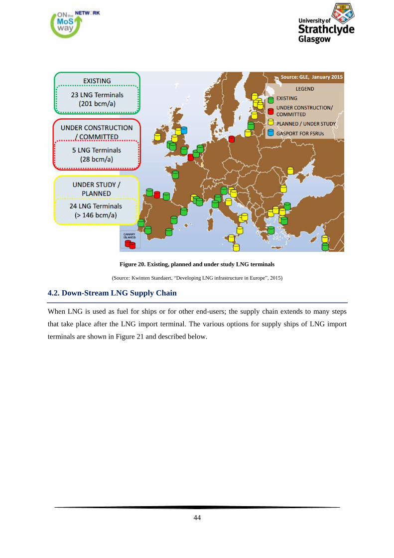
44
Figure 20. Existing, planned and under study LNG terminals
(Source: Kwinten Standaert, “Developing LNG infrastructure in Europe”, 2015)
4.2. Down-Stream LNG Supply Chain
When LNG is used as fuel for ships or for other end-users; the supply chain extends to many steps
that take place after the LNG import terminal. The various options for supply ships of LNG import
terminals are shown in Figure 21 and described below.
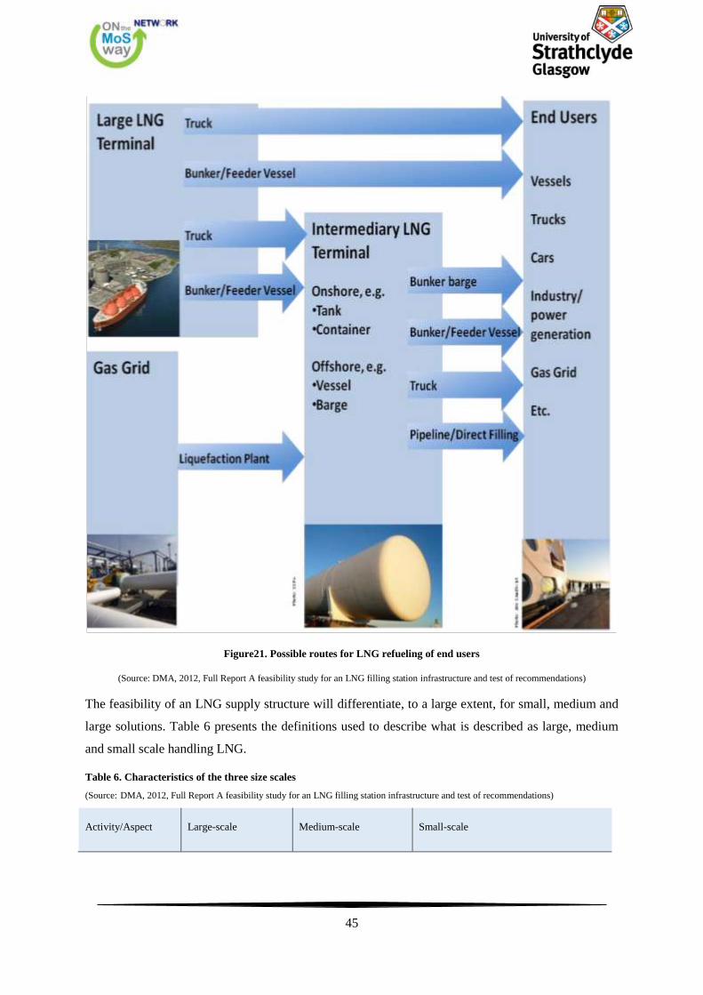
45
Figure21. Possible routes for LNG refueling of end users
(Source: DMA, 2012, Full Report A feasibility study for an LNG filling station infrastructure and test of recommendations)
The feasibility of an LNG supply structure will differentiate, to a large extent, for small, medium and
large solutions. Table 6 presents the definitions used to describe what is described as large, medium
and small scale handling LNG.
Table 6. Characteristics of the three size scales
(Source: DMA, 2012, Full Report A feasibility study for an LNG filling station infrastructure and test of recommendations)
Activity/Aspect Large-scale Medium-scale Small-scale
46
On shore storage
capacity
Import terminal
≥ 100.000 m3
Intermediary terminal
10.000-100.000 m3
Intermediary terminal
< 10.000 m3
Ship size, LNG
capacity
LNG carriers
100.000-270.000 m3
LNG feeder vessels
10.00 -100.000 m3
LNG bunker vessels 1.000-10.000 m3
LNG bunker vessels/barges 200-1.000 m3
Tank trucks 40-80 m3
As seen from the table above, the LNG tankers are almost always the same size, about 40-80m3, while
the "bunker vessel" and interim LNG tanks can vary significantly in size. More specifically, the
capacity of LNG carriers to supply ships can range from up to 1.000m3 10.000m
3, depending on the
distance of the location for the supply, the location for refueling, the type of clients served and the
total volume of fuel managed by the refueling station.
It should be noted that intermediate terminals can be powered either by the sea side with "LNG feeder
vessel" or the land side through the gas transmission network. If powered by the land side of the
intermediate terminal, they need natural gas liquefaction installations. The principles regarding the
tanks fueling are the same for both cases.
The small-scale liquefaction plants are usually a profitable investment because the funds required are
reasonable. In addition, the compact size of these facilities provides the ability to produce LNG near
to where it will be used, since these facilities make it possible for customers who do not have access
to gas pipelines. The LNG is usually transferred from these facilities in industries and other customers
by special LNG tankers or ships LNG.
4.2.1. Intermediary LNG Terminals
Intermediate LNG terminals can be used if the distance between the terminals LNG imports by end
users is more than is economically feasible to meet from "bunker vessel" or LNG tank. The range of
economically feasible distance is up to 100 nautical miles (185 km) for the "bunker vessel", based on
current practices and up to 500 km for LNG Tanker. This distance depends largely on the size of tank
that allows different countries.
Intermediate terminals may vary widely in size. Implemented full scale on a large harbor, the
intermediate terminal can be quite large, for example 100.000m3, while an intermediate terminal
which serves small fishing boats or trailers through ductwork at the dock can be equipped with several
small capacity tanks, as for instance 50m3.
The LNG storage tanks can be terrestrial, mobile or floating. Many of the existing intermediate
terminals have storage onshore LNG tanks. The mobile storage tanks LNG (LNG Containers) which
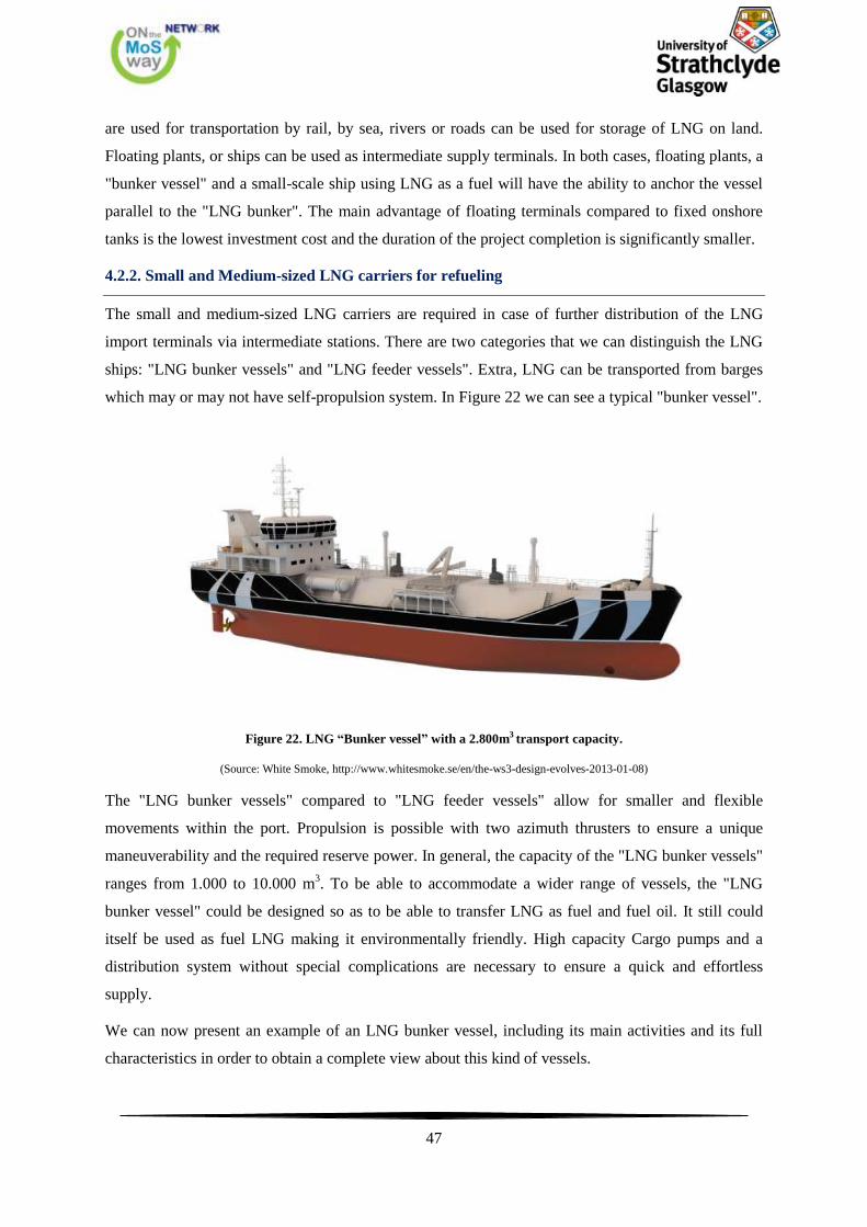
47
are used for transportation by rail, by sea, rivers or roads can be used for storage of LNG on land.
Floating plants, or ships can be used as intermediate supply terminals. In both cases, floating plants, a
"bunker vessel" and a small-scale ship using LNG as a fuel will have the ability to anchor the vessel
parallel to the "LNG bunker". The main advantage of floating terminals compared to fixed onshore
tanks is the lowest investment cost and the duration of the project completion is significantly smaller.
4.2.2. Small and Medium-sized LNG carriers for refueling
The small and medium-sized LNG carriers are required in case of further distribution of the LNG
import terminals via intermediate stations. There are two categories that we can distinguish the LNG
ships: "LNG bunker vessels" and "LNG feeder vessels". Extra, LNG can be transported from barges
which may or may not have self-propulsion system. In Figure 22 we can see a typical "bunker vessel".
Figure 22. LNG “Bunker vessel” with a 2.800m3 transport capacity.
(Source: White Smoke, http://www.whitesmoke.se/en/the-ws3-design-evolves-2013-01-08)
The "LNG bunker vessels" compared to "LNG feeder vessels" allow for smaller and flexible
movements within the port. Propulsion is possible with two azimuth thrusters to ensure a unique
maneuverability and the required reserve power. In general, the capacity of the "LNG bunker vessels"
ranges from 1.000 to 10.000 m3. To be able to accommodate a wider range of vessels, the "LNG
bunker vessel" could be designed so as to be able to transfer LNG as fuel and fuel oil. It still could
itself be used as fuel LNG making it environmentally friendly. High capacity Cargo pumps and a
distribution system without special complications are necessary to ensure a quick and effortless
supply.
We can now present an example of an LNG bunker vessel, including its main activities and its full
characteristics in order to obtain a complete view about this kind of vessels.
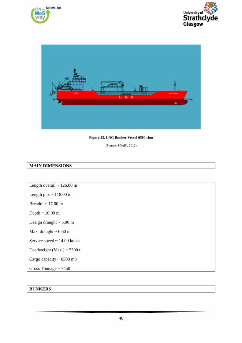
48
Figure 23. LNG Bunker Vessel 6500 cbm
(Source: SDARI, 2012)
MAIN DIMENSIONS
Length overall ~ 126.00 m
Length p.p. ~ 118.00 m
Breadth ~ 17.60 m
Depth ~ 10.00 m
Design draught ~ 5.90 m
Max. draught ~ 6.60 m
Service speed ~ 14.00 knots
Deadweight (Max.) ~ 5500 t
Cargo capacity ~ 6500 m3
Gross Tonnage ~ 7450
BUNKERS
49
Marine diesel oil/Marine gas oil ~ 450 m3
Fresh water ~ 120 m3
Lubricating oil ~ 10 m3
Thermal oil ~ 10 m3
Ballast water ~ 2300 m3
FUEL CONSUMPTION
Main alternator engines
Running on gas mode
LNG ~ 14.6 t/day
MDO pilot fuel ~ 0.32 t/day
Running on diesel mode
MDO ~ 18.1 t/day
DIESEL-ELECTRIC POWERING
Main diesel/gas driven engine/alternators
Number ~ 3 sets
Engine type Wartsila 6L20DF
Output/Speed ~ 1110 kW / 1200rpm
Alternator output ~ 1065 kW
Engine type Wartsila 8L20DF
Output/Speed ~ 1480 kW / 1200rpm
Alternator output ~ 1420 kW
Engine type Wartsila 6L34DF
Output/Speed ~ 2880 kW / 720rpm
Alternator output ~ 2770 kW
Emergency Generator
50
Output ~ 1 × 300 kW
MAIN PROPULSION PLANT
Main electric propulsion motors
Output ~ 2 × 1450 kW
Main propulsion units
Type ~ 2 × Azimuthing thrusters
Propeller material ~ Nickel-aluminium-bronze
Pitch ~ Fixed
Diameter, each ~ 2300 mm
Speed at MCR ~ 250 rpm, inward
BOW THRUSTER
Type ~ Tunnel type, electric, CP propeller
Output ~ 1 × abt. 680 kW (10t thruster force)
BOILER
Number ~ 2 sets
Type ~ Oil fired thermal oil heater, abt. 680 kW /
Exhaust gas thermal oil heater, abt. 500 kW
GAS HANDLING SYSTEM
Cargo tanks
Type ~ 2 × abt. 3250 m3, cylindrical
Max. Density for design ~ 0.65 t/m3
51
Min. cargo temperature ~ -163 oC
Tank material ~ 9% Ni Steel
Piping material ~ Stainless steel
Thermal insulation ~ Polyurethane slabs with galvanized steel sheets
Cargo Pumps
Type ~ 2 × abt. 550 m3/h, deepwell
Max. Density for design ~ 0.50 t/m3
Reliquefaction Plant
Type ~ 1 × abt. 9 t/day
Bunker Arm
Type ~ 1 × 1000 m3/h
Gas Combustion Unit
Type ~ 1 × abt. 1.3 t/h
Nitrogen Generation System
Number ~ 2 sets
Type ~ Membrane type / PSA type
MOORING EQUIPMENT
Mooring winches
2 sets (fore) / 2 sets (mid) / 2 sets (aft)
Fenders
4 × 3.3 m dia. (mid) / 4 × 1.0 m dia. (fore / aft)
COMPLEMENT
Officers ~ 9 P
Crews ~ 10 P
Suez Crews ~ 4 P
52
Main activities:
Receive LNG from a shore terminal
Receive LNG from LNG carrier
Discharge LNG to shore storage tank
Transfer LNG internally between its own cargo tanks
Transfer LNG to receiving ship
Empty its own cargo tanks
Warm up its own cargo tanks and LNG bunker tank of receiving ship
Supply dry inert gas to itself and receiving ship
Gas up its own cargo tanks and LNG bunker tank of receiving ship
Cool down tanks and LNG cargo lines of both itself and receiving ship
Due to the fact that this paper focuses on the design, it would be helpful to present a general
arrangement of another LNG Bunker vessel with the main particulars below:
LOA = 68m
LPP = 63m
DWT = 1400 tons
B = 13 m
DDESIGN = 4m
DSCANTLING = 4.5m
HFO = 600 m3 (0 m
3)
MDO = 520 m3 (520 m
3/1000 m
3)
LNG = 700 m3 (1000 m
3/1400 m
3)
Main Power Prod. = 2 x 841 kWe
Aux Power Prod. = 1 x 400 and 1 x 200 kWe
Speed = 11kn
Main propulsion = 2 x 750 kW

53
Bow Thruster = 1 x 200 Kw
Crew = 4-7
54
55
The basic aim of "LNG feeder vessels" is the regional distribution of marine fuel LNG by large
import terminals to points along the coastline and the possibility of large supply ship in need of large
LNG quantities. The size and dimensions of the main "LNG feeder vessels" may vary considerably
depending on various market demands, depths and other physical port. Typical capacity for a cargo
ship such supply LNG should be 7.000 to 20.000m3. The ship equipment should be designed so as to
make it as flexible as possible to supply taking into account the requirements of LNG as cargo. It still
should have "bow thrusters" and high performance rudder so as not to require the assistance of tugs
for mooring at pier or boat. The main fuel ship could be the LNG, using the vapors from the LNG
storage tanks, but it would be preferable to have dual fuel engine to increase backup propulsion.
As early as March 21, 2013 in the harbor of Stockholm and on behalf of "MS Viking Grace"
(passenger ferry), such a "LNG bunker vessel" is running. The "Seagas", which is illustrated in Figure
24, carries out replenishment daily with 60-70 tonnes of LNG in less than an hour. It is obvious that
the bunker vessel has higher transfer rates for the LNG than Truck to Ship bunkering option.
56
Figure 24. “Segas” perform/s daily LNG refueling on behalf of the passenger ferry "MS Viking Grace"
(Source: Sirius Shipping, http://siriusshipping.eu/our-fleet/seagas/)
In this point, we have the opportunity to observe some figures bellow, from the bunkering operation
of "MS Viking Grace".
Figure 25. Seagas Connected to MS Viking Grace
(Source: Joslin, O. 2015, Small scale LNG Bunkering, safety, standardisation and its regulations)
At the folowing figures we can notice how the crane of Seagas upholds steadily the 6 inches hose in
order to have a proper connection and the bunkering operation can take place.
a
b
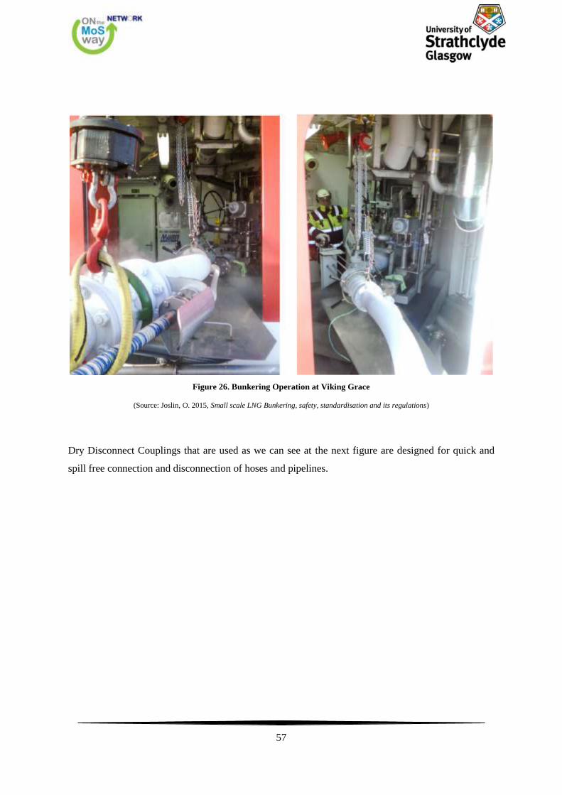
57
Figure 26. Bunkering Operation at Viking Grace
(Source: Joslin, O. 2015, Small scale LNG Bunkering, safety, standardisation and its regulations)
Dry Disconnect Couplings that are used as we can see at the next figure are designed for quick and
spill free connection and disconnection of hoses and pipelines.
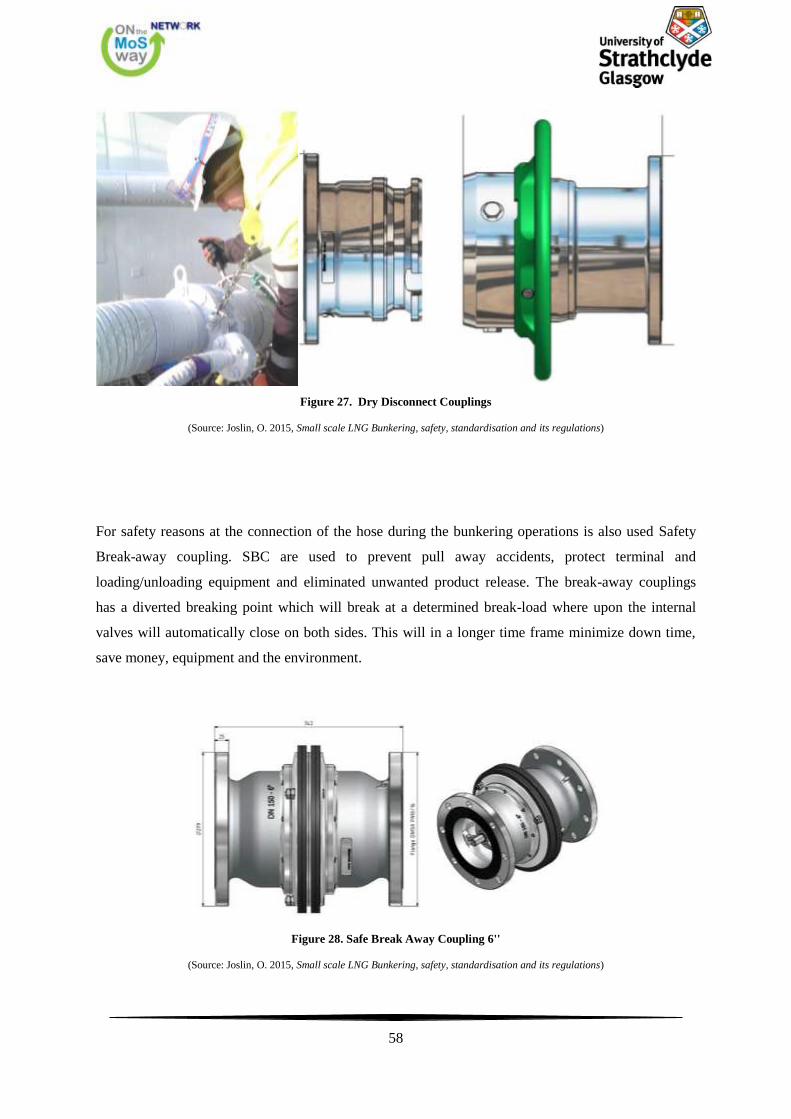
58
Figure 27. Dry Disconnect Couplings
(Source: Joslin, O. 2015, Small scale LNG Bunkering, safety, standardisation and its regulations)
For safety reasons at the connection of the hose during the bunkering operations is also used Safety
Break-away coupling. SBC are used to prevent pull away accidents, protect terminal and
loading/unloading equipment and eliminated unwanted product release. The break-away couplings
has a diverted breaking point which will break at a determined break-load where upon the internal
valves will automatically close on both sides. This will in a longer time frame minimize down time,
save money, equipment and the environment.
Figure 28. Safe Break Away Coupling 6''
(Source: Joslin, O. 2015, Small scale LNG Bunkering, safety, standardisation and its regulations)
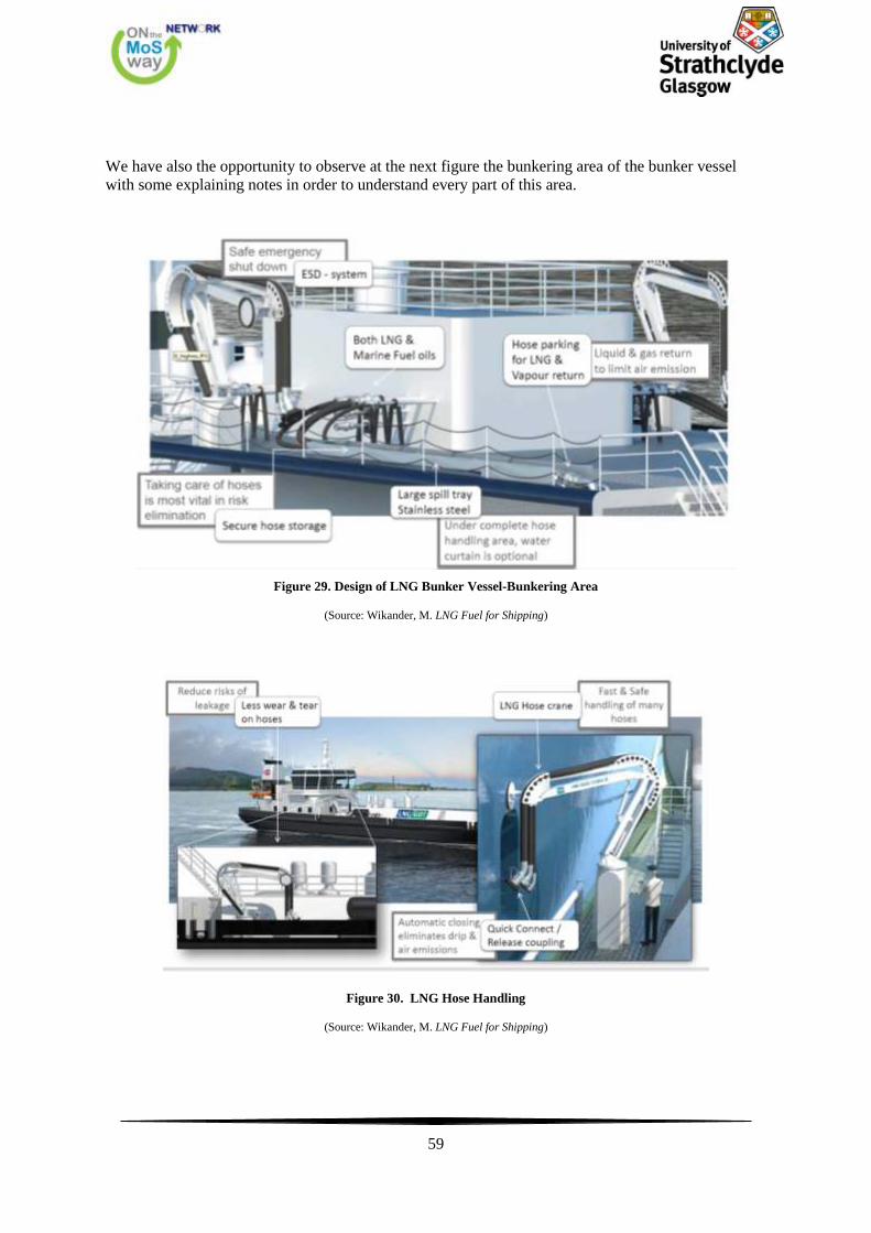
59
We have also the opportunity to observe at the next figure the bunkering area of the bunker vessel
with some explaining notes in order to understand every part of this area.
Figure 29. Design of LNG Bunker Vessel-Bunkering Area
(Source: Wikander, M. LNG Fuel for Shipping)
Figure 30. LNG Hose Handling
(Source: Wikander, M. LNG Fuel for Shipping)
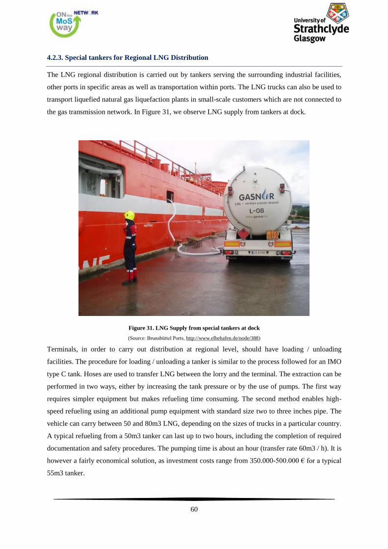
60
4.2.3. Special tankers for Regional LNG Distribution
The LNG regional distribution is carried out by tankers serving the surrounding industrial facilities,
other ports in specific areas as well as transportation within ports. The LNG trucks can also be used to
transport liquefied natural gas liquefaction plants in small-scale customers which are not connected to
the gas transmission network. In Figure 31, we observe LNG supply from tankers at dock.
Figure 31. LNG Supply from special tankers at dock
(Source: Brunsbüttel Ports, http://www.elbehafen.de/node/388)
Terminals, in order to carry out distribution at regional level, should have loading / unloading
facilities. The procedure for loading / unloading a tanker is similar to the process followed for an IMO
type C tank. Hoses are used to transfer LNG between the lorry and the terminal. The extraction can be
performed in two ways, either by increasing the tank pressure or by the use of pumps. The first way
requires simpler equipment but makes refueling time consuming. The second method enables high-
speed refueling using an additional pump equipment with standard size two to three inches pipe. The
vehicle can carry between 50 and 80m3 LNG, depending on the sizes of trucks in a particular country.
A typical refueling from a 50m3 tanker can last up to two hours, including the completion of required
documentation and safety procedures. The pumping time is about an hour (transfer rate 60m3 / h). It is
however a fairly economical solution, as investment costs range from 350.000-500.000 € for a typical
55m3 tanker.

61
We can observe below how "MS Viking Grace", that we mentioned earlier, is bunkered by a truck.
Figure 32. Truck to Ship Bunkering Operation
4.2.4. LNG transport via pipelines
LNG transfer through pipeline networks over long distances is a difficult and expensive technique.
Therefore, it is expected that the use of pipelines is limited in distribution to filling stations supplying
LNG (tanks) and when the distances between the regulatory milestone for the pressure of the natural
gas and LNG refueling stopover is small.
Concerns exist about the phenomenon of "boil off gas" evaporation in the ducts, especially when the
LNG is not used. There are two main ways of tackling the problems of LNG pipelines when not in
use:
The continuous release of LNG in the pipeline can be carried out to minimize the time
temperature reduction until the next time the pipeline is in use. This method has the effect of
increasing the intensity of the "boil off" phenomenon which should be taken into account. If the
pipework connected to the terminal, this station will be able to use the "boil off" the conductors. It
should be noted that a full pipeline involves high levels of risk compared with an empty.
62
The conduit emptying after each use usually requires nitrogen. The problem is that nitrogen can
have an infecting effect when used on a large scale. A pipeline which is filled with nitrogen may
need to be be filled with natural gas before cooling. This is time consuming and inefficient.
4.2.5. Gas Conversion to Liquid
Before distributing the gas to the end user, the pressure in the pipeline should be reduced. Therefore,
processes can be used for expansion to take advantage of the pressure difference. This process is
accomplished by venting the gas inlet nearly isentropically through a turbine, thereby reducing the
temperature and partially liquefying the gas. An LNG plant of this type must of course be located in
the natural gas transmission line, however, the LNG could be shipped to another location.
This could be done with existing commercial systems, if the pressure reduction is quite great. Data
show that 20-30% of the gas volume can be produced as LNG. So far the main purpose of the
facilities is to produce LNG as a vehicle fuel. This process could be applied to the provision of LNG
as a marine fuel, mainly small-scale installations.
The great disadvantage by using a system like this is that the use of LNG to be followed by the
characteristics of the gas use. It is likely that the LNG which will be produced at the stations pressure
regulating and metering will be for refueling ships, which have a demand profile that is very different
from that of the pipeline network. Installing a larger tank can probably overcomr this obstacle. There
are other means of production, LNG from natural gas, but this would be very expensive to use. The
typical cost of liquefaction according to the Norwegian management company gas Gasnor is between
150-300 € / tonne.
4.3. LNG Solutions for LNG bunkering
The successful adoption of LNG as a marine fuel is directly dependent on safe and effective supply
companies. The rules and regulations related to the handling of LNG as cargo have thrived for
decades, such as the IMO IGC Code and implemented successfully. Regulatory framework for LNG
handling as a marine fuel is under development. Even rules and regulations have been developed to
cover the issues of LNG as fuel have several gaps which should be addressed in order to safe and
efficient use. Although the infrastructure for refueling LNG in Europe is still at an early stage, the
technical and operational aspects of solutions for the supply of ships under discussion.
Below are three main ways of ship with LNG as a marine fuel. As shown in Figure 33, the three main
ways refueling are:
Ship-to-Ship, STS
Truck-to-Ship, TTS
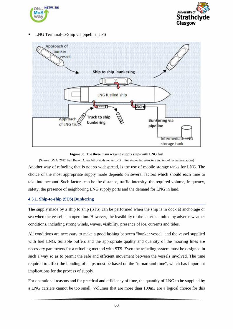
63
LNG Terminal-to-Ship via pipeline, TPS
Figure 33. The three main ways to supply ships with LNG fuel
(Source: DMA, 2012, Full Report A feasibility study for an LNG filling station infrastructure and test of recommendations)
Another way of refueling that is not so widespread, is the use of mobile storage tanks for LNG. The
choice of the most appropriate supply mode depends on several factors which should each time to
take into account. Such factors can be the distance, traffic intensity, the required volume, frequency,
safety, the presence of neighboring LNG supply ports and the demand for LNG in land.
4.3.1. Ship-to-ship (STS) Bunkering
The supply made by a ship to ship (STS) can be performed when the ship is in dock at anchorage or
sea when the vessel is in operation. However, the feasibility of the latter is limited by adverse weather
conditions, including strong winds, waves, visibility, presence of ice, currents and tides.
All conditions are necessary to make a good lashing between "bunker vessel" and the vessel supplied
with fuel LNG. Suitable buffers and the appropriate quality and quantity of the mooring lines are
necessary parameters for a refueling method with STS. Even the refueling system must be designed in
such a way so as to permit the safe and efficient movement between the vessels involved. The time
required to effect the bonding of ships must be based on the "turnaround time", which has important
implications for the process of supply.
For operational reasons and for practical and efficiency of time, the quantity of LNG to be supplied by
a LNG carriers cannot be too small. Volumes that are more than 100m3 are a logical choice for this
64
supply mode. Typical ship capacities for refueling can range from 1.000 to 10.000m3. Small ships or
barges can also be used in some ports with capacities under 1.000m3.
The fuel supply via STS is expected to be the main method of refueling ships required for fuel
volumes more than 100 m3, due to a high degree of flexibility, which allows all types of ships to serve
both the dock and at sea. The average bunkering rate in this way of bunkering operation is 150-200
m3/h.
In Figure 34 below, we can observe the required processes to be carried out according to a typical
scenario of supply and the time required for its completion. The ship on which was the refueling
scenario is based is a Ro-Pax for short distances, which is considered suitable for the use of LNG as a
marine fuel. The refueling in port is located near urban areas. Basic requirements of the scenario are
the high levels of safety and short refueling time. The required amount of fuel is set at 130 m3 ≈ 65
ton.
The maximum time refueling including mooring is set to 50 minutes. Seatbelts are set approximately
10m round from every point of the piping system. To make it easier to separate the process, the
supply can be categorized into three time phases: before, during and after refueling. However it
should be noted that for other types of vessels operating on different routes, fuel volumes is of course
different, and so is the time required for refueling.

65
Figure 34. A typical LNG supply timeline
(Source: Swedish Marine Technology Forum, 2010, LNG ship to ship bunkering procedure)
4.3.2. Truck-to-Ship bunkering, TTS
The supply of specially designed tanker is currently the most widespread form of ship supply with
fuel LNG. The main advantage of the tank is that it is specially shaped to be inexpensive compared to
other alternatives. The supply takes place at the pier, where the tanker is parked, through a system of
flexible pipes. A major drawback of this method is that the ships supply is not fast enough, so this
supply mode is suitable for small fuel volumes, app. 100-200m3. Moreover, there could be a
significant negative impact on operations which can be performed in parallel with a supply such of
loads handling and embarkation / disembarkation of passengers, given that the supply is made by the
side of the pier. Another obvious limitation is that the preferred site for its refueling should be linked
by road to filling station LNG, which should have special facilities and equipment in order to be able
to allow the loading / unloading of tankers. The average bunkering rate in this way of bunkering
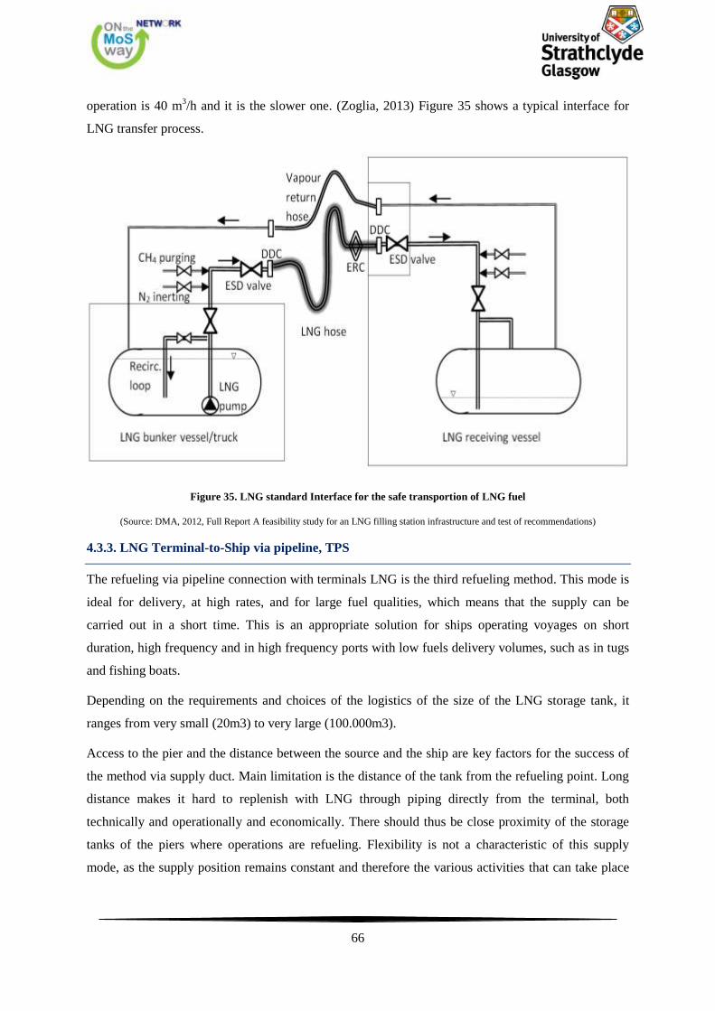
66
operation is 40 m3/h and it is the slower one. (Zoglia, 2013) Figure 35 shows a typical interface for
LNG transfer process.
Figure 35. LNG standard Interface for the safe transportion of LNG fuel
(Source: DMA, 2012, Full Report A feasibility study for an LNG filling station infrastructure and test of recommendations)
4.3.3. LNG Terminal-to-Ship via pipeline, TPS
The refueling via pipeline connection with terminals LNG is the third refueling method. This mode is
ideal for delivery, at high rates, and for large fuel qualities, which means that the supply can be
carried out in a short time. This is an appropriate solution for ships operating voyages on short
duration, high frequency and in high frequency ports with low fuels delivery volumes, such as in tugs
and fishing boats.
Depending on the requirements and choices of the logistics of the size of the LNG storage tank, it
ranges from very small (20m3) to very large (100.000m3).
Access to the pier and the distance between the source and the ship are key factors for the success of
the method via supply duct. Main limitation is the distance of the tank from the refueling point. Long
distance makes it hard to replenish with LNG through piping directly from the terminal, both
technically and operationally and economically. There should thus be close proximity of the storage
tanks of the piers where operations are refueling. Flexibility is not a characteristic of this supply
mode, as the supply position remains constant and therefore the various activities that can take place
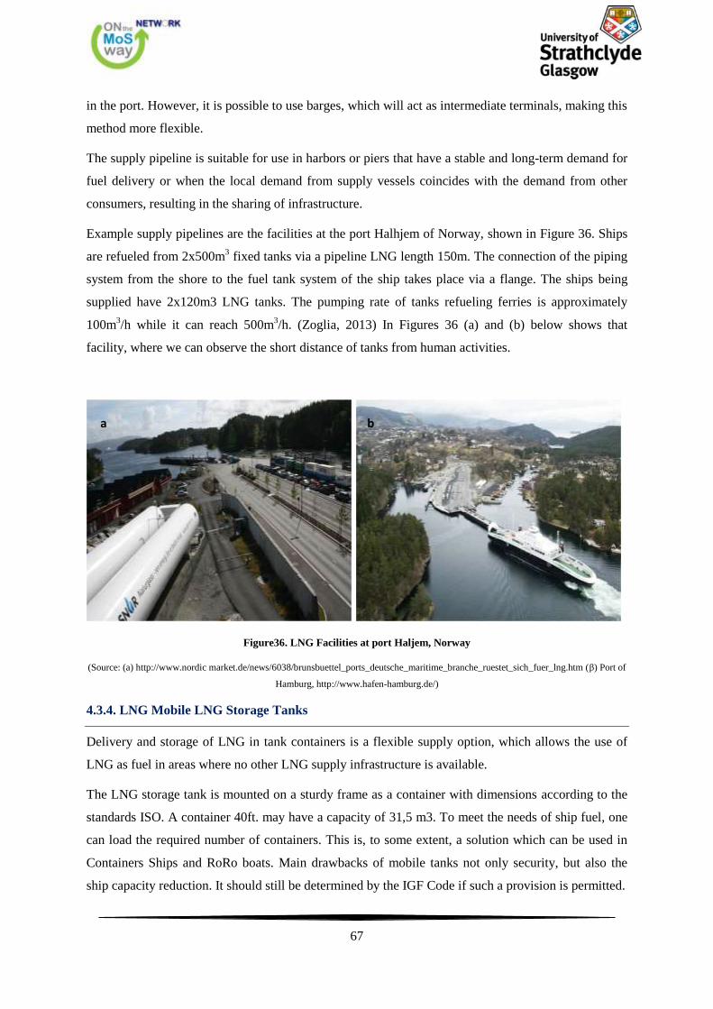
67
in the port. However, it is possible to use barges, which will act as intermediate terminals, making this
method more flexible.
The supply pipeline is suitable for use in harbors or piers that have a stable and long-term demand for
fuel delivery or when the local demand from supply vessels coincides with the demand from other
consumers, resulting in the sharing of infrastructure.
Example supply pipelines are the facilities at the port Halhjem of Norway, shown in Figure 36. Ships
are refueled from 2x500m3 fixed tanks via a pipeline LNG length 150m. The connection of the piping
system from the shore to the fuel tank system of the ship takes place via a flange. The ships being
supplied have 2x120m3 LNG tanks. The pumping rate of tanks refueling ferries is approximately
100m3/h while it can reach 500m
3/h. (Zoglia, 2013) In Figures 36 (a) and (b) below shows that
facility, where we can observe the short distance of tanks from human activities.
Figure36. LNG Facilities at port Haljem, Norway
(Source: (a) http://www.nordic market.de/news/6038/brunsbuettel_ports_deutsche_maritime_branche_ruestet_sich_fuer_lng.htm (β) Port of
Hamburg, http://www.hafen-hamburg.de/)
4.3.4. LNG Mobile LNG Storage Tanks
Delivery and storage of LNG in tank containers is a flexible supply option, which allows the use of
LNG as fuel in areas where no other LNG supply infrastructure is available.
The LNG storage tank is mounted on a sturdy frame as a container with dimensions according to the
standards ISO. A container 40ft. may have a capacity of 31,5 m3. To meet the needs of ship fuel, one
can load the required number of containers. This is, to some extent, a solution which can be used in
Containers Ships and RoRo boats. Main drawbacks of mobile tanks not only security, but also the
ship capacity reduction. It should still be determined by the IGF Code if such a provision is permitted.
a b
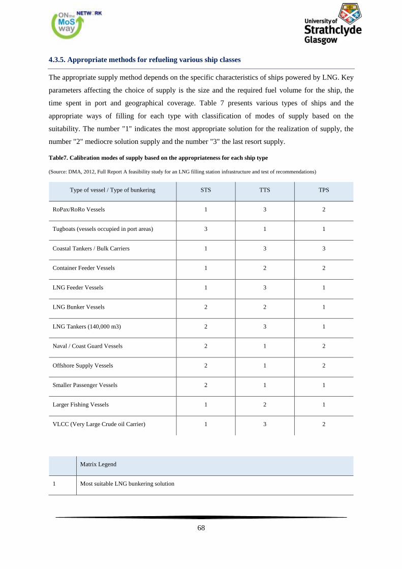
68
4.3.5. Appropriate methods for refueling various ship classes
The appropriate supply method depends on the specific characteristics of ships powered by LNG. Key
parameters affecting the choice of supply is the size and the required fuel volume for the ship, the
time spent in port and geographical coverage. Table 7 presents various types of ships and the
appropriate ways of filling for each type with classification of modes of supply based on the
suitability. The number "1" indicates the most appropriate solution for the realization of supply, the
number "2" mediocre solution supply and the number "3" the last resort supply.
Table7. Calibration modes of supply based on the appropriateness for each ship type
(Source: DMA, 2012, Full Report A feasibility study for an LNG filling station infrastructure and test of recommendations)
Type of vessel / Type of bunkering STS TTS TPS
RoPax/RoRo Vessels 1 3 2
Tugboats (vessels occupied in port areas) 3 1 1
Coastal Tankers / Bulk Carriers 1 3 3
Container Feeder Vessels 1 2 2
LNG Feeder Vessels 1 3 1
LNG Bunker Vessels 2 2 1
LNG Tankers (140,000 m3) 2 3 1
Naval / Coast Guard Vessels 2 1 2
Offshore Supply Vessels 2 1 2
Smaller Passenger Vessels 2 1 1
Larger Fishing Vessels 1 2 1
VLCC (Very Large Crude oil Carrier) 1 3 2
Matrix Legend
1 Most suitable LNG bunkering solution
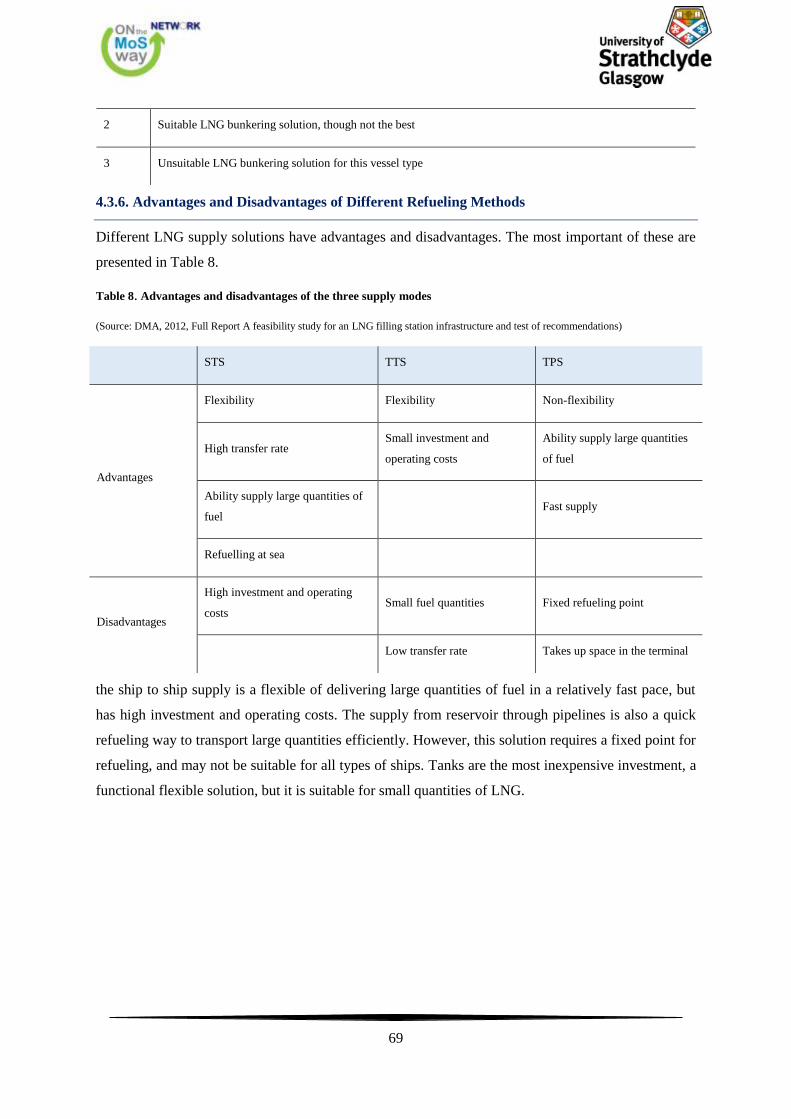
69
2 Suitable LNG bunkering solution, though not the best
3 Unsuitable LNG bunkering solution for this vessel type
4.3.6. Advantages and Disadvantages of Different Refueling Methods
Different LNG supply solutions have advantages and disadvantages. The most important of these are
presented in Table 8.
Table 8. Advantages and disadvantages of the three supply modes
(Source: DMA, 2012, Full Report A feasibility study for an LNG filling station infrastructure and test of recommendations)
STS TTS TPS
Advantages
Flexibility Flexibility Non-flexibility
High transfer rate Small investment and
operating costs
Ability supply large quantities
of fuel
Ability supply large quantities of
fuel Fast supply
Refuelling at sea
Disadvantages
High investment and operating
costs Small fuel quantities Fixed refueling point
Low transfer rate Takes up space in the terminal
the ship to ship supply is a flexible of delivering large quantities of fuel in a relatively fast pace, but
has high investment and operating costs. The supply from reservoir through pipelines is also a quick
refueling way to transport large quantities efficiently. However, this solution requires a fixed point for
refueling, and may not be suitable for all types of ships. Tanks are the most inexpensive investment, a
functional flexible solution, but it is suitable for small quantities of LNG.
70
5. Design of LNG fueled vessel
5.1. Philosophy of Design
5.1.1. What is Design?
Design and Designer tend to be overused words for which there are many definitions.
However it is not always easy to agree on the right definition. Here are some candidates for the
position:
Design is the visualisation and depiction of form.
Design is the mental process which must intervene between the conception of a specific
engineering intention and the issue of drawings to the workshop.
Design is the optimum solution to the sum of the true needs of a particular set of circumstances.
Design is a creative, iterative process serving a bounded objective.
Mechanical Engineering Design is the use of scientific principles, technical information and
imagination in the definition of a mechanical structure, machine or system to perform pre-
specified functions with the maximum economy and efficiency.
The Designer is clearly the paragon who carries out such tasks. His/her work can be split into three
areas of activity:
Decision-making regarding the physical form and dimensions of the product.
Communication to the builder, mainly in the form of drawings and specifications (Graphics, Text
and Computer Files).
Responsibility for the achievement of the original requirements.
Often the designer must guide the original requirements to limit them to the possible.
5.1.2. The Design Team
In this class we are concerned with ships and other marine structures which are sufficiently large that
they are unlikely to be designed by one person acting alone. The work must be shared by a team,
many of whose members will be specialists in one sub-section of the work. The main duty of the chief
designer is then to ensure proper co-ordination of the team members and to maintain a balanced
overall view of the design. This may involve taking all of the important decisions and examining the
associated plans. For peace of mind the successful chief designer must have an almost instinctive
ability to notice errors and query impossible assumptions.
71
In this Class and the associated Design Projects Classes you will be largely working as individual
designers practising the basic technical skills. In later years of the course you can expect to work as
Design Teams where some of the wider skills will be developed and tested.
It is important always to be aware of these wider skills and to remember that when you make a
decision you should record it and, what is often more important, why you made it, so that you can
communicate it to someone else or accept responsibility for it at a later time and be able to justify it.
5.1.3. What is Design Philosophy?
Philosophy might seem a somewhat grand word to use in the context of design but, in the sense of a
body of broad principles, concepts and methods which underpin a given branch of learning, it is a
meaningful one to use. A philosophy does not determine the detailed action to be taken in particular
applications, but it does lead to the development of theories, rules and laws and to detailed methods of
applying them. These form the discipline of design.
There is no single philosophy which satisfies all situations so the aim must be to develop a philosophy
which leads to a consistent set of general principles on which the discipline can be based. This
pragmatic approach requires that the outcome of applying the general principles in a particular
situation must be evaluated against some appropriate criteria of success so that the principles and the
associated discipline can, if necessary, be modified for future applications. The feed-back mechanism
is an essential component of both the philosophy and the discipline.
The following is a list of terms, aspects and concepts which reveal some of the general principles
arising in design:
Morphology. There is a pattern of events and activities which, by and large, are common to all
projects.
Design Process. Iteration to solve problems followed by feedback of information from a later
stage to review decisions made earlier.
Stratification. As the solution to one problem emerges, a sub-stratum of lesser problems is
uncovered. Solutions to these must be found before the original problem can be solved.
Convergence. Many possible solutions may be processed in search of the one correct solution.
Decision-making. Choosing between alternatives.
Analysis. Used to establish the characteristics of the product which is the subject of the design.
This is a fundamental design tool because it forms the basis on which decisions can be made but it
72
is not the starting point for a design. A first shot must have been made at what the whole product
will be like.
Synthesis. This is the truly creative part of design putting together separate elements into a
coherent whole. Probably this is the most characteristic part of design.
Creativity. Inventiveness obviously a highly desirable facility in a designer.
Practicability. What can be achieved in design is determined not only by what is technologically
practicable but also by the capabilities of the design team.
Communication. A design is a description of a product and the instructions for its manufacture.
The quality of the end product depends critically on how well these two aspects are
communicated.
Dynamics. Design is not a static process, especially with a large and complex product. Change in
requirements or solution is almost unavoidable.
Need. The need for the product must be clearly established before starting design work.
Economic Worth. The owner of the end product must feel that it is worth the true cost of its
acquisition.
Optimisation. In design terms it may not be possible to devise the optimum solution, where the
optimum is determined relative to many disparate constraints and on the basis of incomplete data.
The best available solution may be no more than the best compromise that can be made between
conflicting qualities within the constraints.
Criteria. The objective and quantitative measure of how successful or how near the optimum the
design is. Sometimes the criteria are subjective and qualitative the result of value judgements by
those involved in the process.
Systems Approach. When a product is part of a broader system (and very few exist in complete
isolation) its design must take account of the impact of the rest of the system on it and vice versa.

73
5.2. LNG Engine Choices
The use of LNG as a marine fuel started from the LNG carrier industry. The first DF engine
was delivered in 2004 (GDF SUEZ GLOBAL ENERGY). In recent years the dual-fuel engine
technology has been included in the marine market. Primarily through applications into LNG carriers
or even ferry and patrol boats in Norway.
Figure 37. Mitsubishi GS16R-MPTK, source Diesel Power
(Source: ABS, 2011, LNG Powered Vessels amd the ABS Guide for the propulsion and auxiliary Systems for ZGas fueled Ships)
Figure 38. Rolls Royce Bergen C26:33, source: Rolls Royce
(Source: ABS, 2011, LNG Powered Vessels amd the ABS Guide for the propulsion and auxiliary Systems for ZGas fueled Ships)
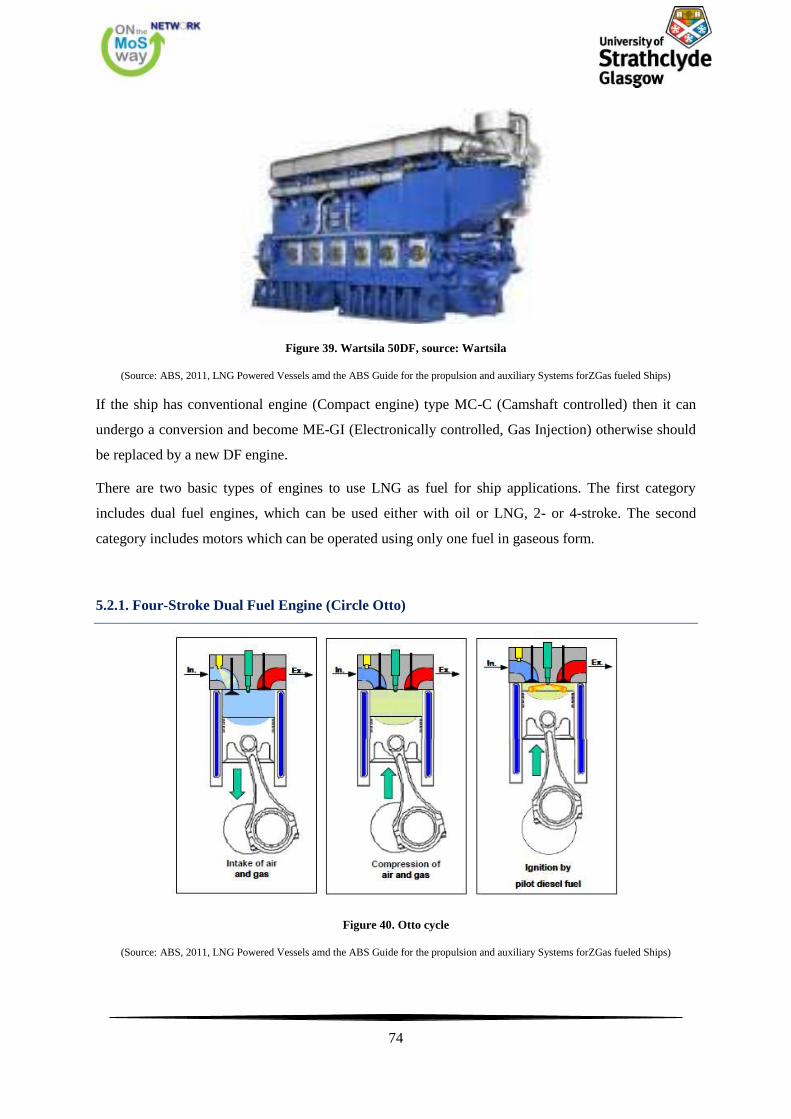
74
Figure 39. Wartsila 50DF, source: Wartsila
(Source: ABS, 2011, LNG Powered Vessels amd the ABS Guide for the propulsion and auxiliary Systems forZGas fueled Ships)
If the ship has conventional engine (Compact engine) type MC-C (Camshaft controlled) then it can
undergo a conversion and become ME-GI (Electronically controlled, Gas Injection) otherwise should
be replaced by a new DF engine.
There are two basic types of engines to use LNG as fuel for ship applications. The first category
includes dual fuel engines, which can be used either with oil or LNG, 2- or 4-stroke. The second
category includes motors which can be operated using only one fuel in gaseous form.
5.2.1. Four-Stroke Dual Fuel Engine (Circle Otto)
Figure 40. Otto cycle
(Source: ABS, 2011, LNG Powered Vessels amd the ABS Guide for the propulsion and auxiliary Systems forZGas fueled Ships)
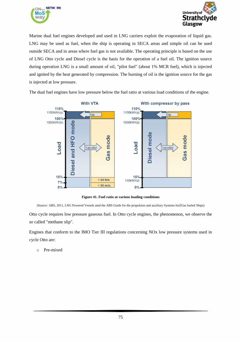
75
Marine dual fuel engines developed and used in LNG carriers exploit the evaporation of liquid gas.
LNG may be used as fuel, when the ship is operating in SECA areas and simple oil can be used
outside SECA and in areas where fuel gas is not available. The operating principle is based on the use
of LNG Otto cycle and Diesel cycle is the basis for the operation of a fuel oil. The ignition source
during operation LNG is a small amount of oil, "pilot fuel" (about 1% MCR fuel), which is injected
and ignited by the heat generated by compression. The burning of oil is the ignition source for the gas
is injected at low pressure.
The dual fuel engines have low pressure below the fuel ratio at various load conditions of the engine.
Figure 41. Fuel ratio at various loading conditions
(Source: ABS, 2011, LNG Powered Vessels amd the ABS Guide for the propulsion and auxiliary Systems forZGas fueled Ships)
Otto cycle requires low pressure gaseous fuel. In Otto cycle engines, the phenomenon, we observe the
so called "methane slip".
Engines that conform to the IMO Tier III regulations concerning NOx low pressure systems used in
cycle Otto are:
o Pre-mixed
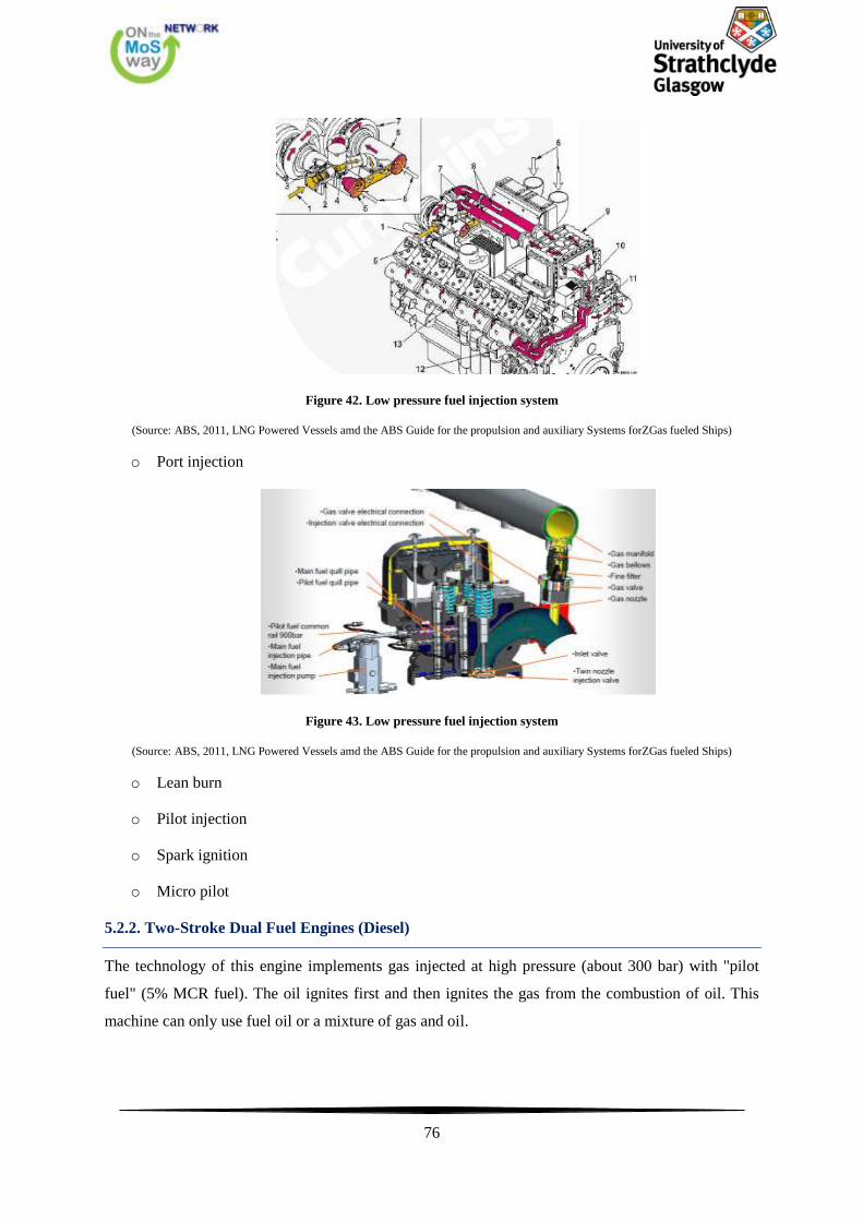
76
Figure 42. Low pressure fuel injection system
(Source: ABS, 2011, LNG Powered Vessels amd the ABS Guide for the propulsion and auxiliary Systems forZGas fueled Ships)
o Port injection
Figure 43. Low pressure fuel injection system
(Source: ABS, 2011, LNG Powered Vessels amd the ABS Guide for the propulsion and auxiliary Systems forZGas fueled Ships)
o Lean burn
o Pilot injection
o Spark ignition
o Micro pilot
5.2.2. Two-Stroke Dual Fuel Engines (Diesel)
The technology of this engine implements gas injected at high pressure (about 300 bar) with "pilot
fuel" (5% MCR fuel). The oil ignites first and then ignites the gas from the combustion of oil. This
machine can only use fuel oil or a mixture of gas and oil.
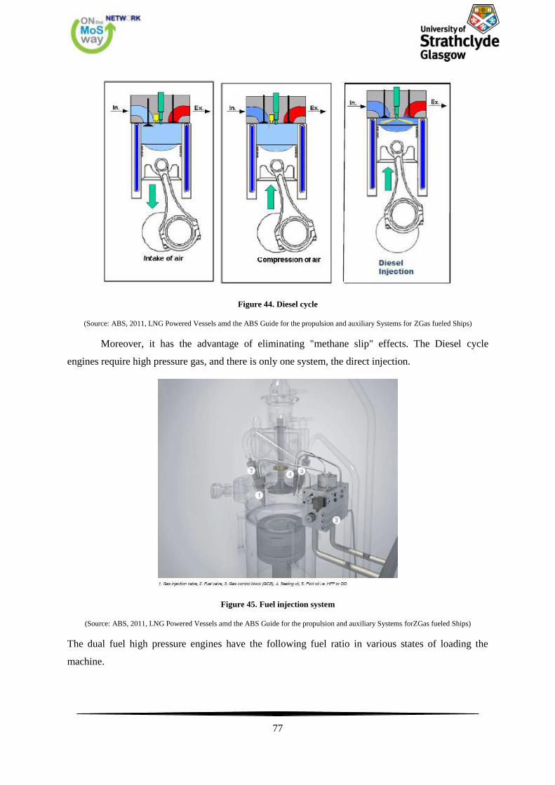
77
Figure 44. Diesel cycle
(Source: ABS, 2011, LNG Powered Vessels amd the ABS Guide for the propulsion and auxiliary Systems for ZGas fueled Ships)
Moreover, it has the advantage of eliminating "methane slip" effects. The Diesel cycle
engines require high pressure gas, and there is only one system, the direct injection.
Figure 45. Fuel injection system
(Source: ABS, 2011, LNG Powered Vessels amd the ABS Guide for the propulsion and auxiliary Systems forZGas fueled Ships)
The dual fuel high pressure engines have the following fuel ratio in various states of loading the
machine.
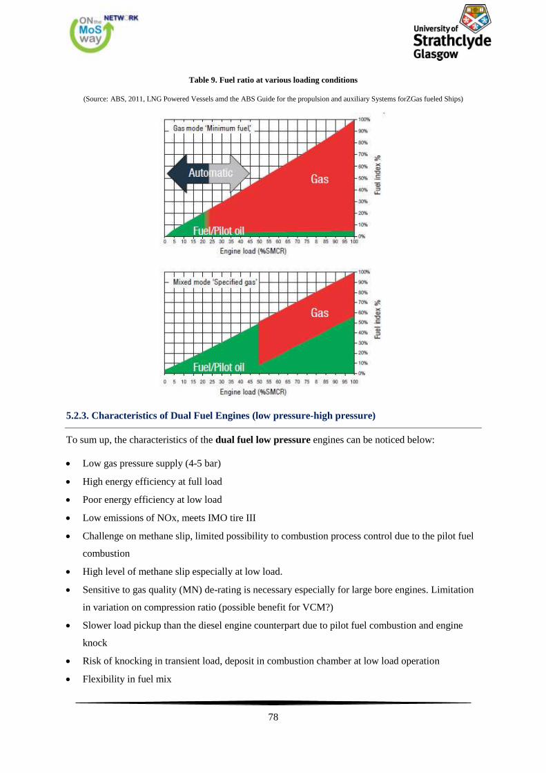
78
Table 9. Fuel ratio at various loading conditions
(Source: ABS, 2011, LNG Powered Vessels amd the ABS Guide for the propulsion and auxiliary Systems forZGas fueled Ships)
5.2.3. Characteristics of Dual Fuel Engines (low pressure-high pressure)
To sum up, the characteristics of the dual fuel low pressure engines can be noticed below:
Low gas pressure supply (4-5 bar)
High energy efficiency at full load
Poor energy efficiency at low load
Low emissions of NOx, meets IMO tire III
Challenge on methane slip, limited possibility to combustion process control due to the pilot fuel
combustion
High level of methane slip especially at low load.
Sensitive to gas quality (MN) de-rating is necessary especially for large bore engines. Limitation
in variation on compression ratio (possible benefit for VCM?)
Slower load pickup than the diesel engine counterpart due to pilot fuel combustion and engine
knock
Risk of knocking in transient load, deposit in combustion chamber at low load operation
Flexibility in fuel mix
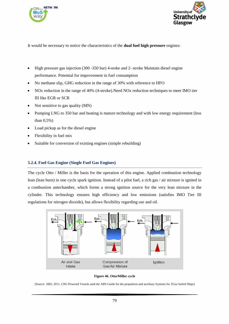
79
It would be necessary to notice the characteristics of the dual fuel high pressure engines:
High pressure gas injection (300 -350 bar) 4-stoke and 2- stroke Maintain diesel engine
performance. Potential for improvement in fuel consumption
No methane slip, GHG reduction in the range of 30% with reference to HFO
NOx reduction in the range of 40% (4-stroke).Need NOx reduction techniques to meet IMO tier
III like EGR or SCR
Not sensitive to gas quality (MN)
Pumping LNG to 350 bar and heating is mature technology and with low energy requirement (less
than 0,5%)
Load pickup as for the diesel engine
Flexibility in fuel mix
Suitable for conversion of existing engines (simple rebuilding)
5.2.4. Fuel Gas Engine (Single Fuel Gas Engines)
The cycle Otto / Miller is the basis for the operation of this engine. Applied combustion technology
lean (lean burn) in one cycle spark ignition. Instead of a pilot fuel, a rich gas / air mixture is ignited in
a combustion antechamber, which forms a strong ignition source for the very lean mixture in the
cylinder. This technology ensures high efficiency and low emissions (satisfies IMO Tier III
regulations for nitrogen dioxide), but allows flexibility regarding use and oil.
Figure 46. Otto/Miller cycle
(Source: ABS, 2011, LNG Powered Vessels amd the ABS Guide for the propulsion and auxiliary Systems for ZGas fueled Ships)
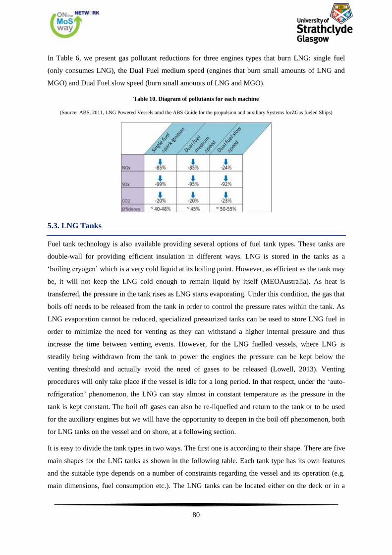
80
In Table 6, we present gas pollutant reductions for three engines types that burn LNG: single fuel
(only consumes LNG), the Dual Fuel medium speed (engines that burn small amounts of LNG and
MGO) and Dual Fuel slow speed (burn small amounts of LNG and MGO).
Table 10. Diagram of pollutants for each machine
(Source: ABS, 2011, LNG Powered Vessels amd the ABS Guide for the propulsion and auxiliary Systems forZGas fueled Ships)
5.3. LNG Tanks
Fuel tank technology is also available providing several options of fuel tank types. These tanks are
double-wall for providing efficient insulation in different ways. LNG is stored in the tanks as a
‘boiling cryogen’ which is a very cold liquid at its boiling point. However, as efficient as the tank may
be, it will not keep the LNG cold enough to remain liquid by itself (MEOAustralia). As heat is
transferred, the pressure in the tank rises as LNG starts evaporating. Under this condition, the gas that
boils off needs to be released from the tank in order to control the pressure rates within the tank. As
LNG evaporation cannot be reduced, specialized pressurized tanks can be used to store LNG fuel in
order to minimize the need for venting as they can withstand a higher internal pressure and thus
increase the time between venting events. However, for the LNG fuelled vessels, where LNG is
steadily being withdrawn from the tank to power the engines the pressure can be kept below the
venting threshold and actually avoid the need of gases to be released (Lowell, 2013). Venting
procedures will only take place if the vessel is idle for a long period. In that respect, under the ‘auto-
refrigeration’ phenomenon, the LNG can stay almost in constant temperature as the pressure in the
tank is kept constant. The boil off gases can also be re-liquefied and return to the tank or to be used
for the auxiliary engines but we will have the opportunity to deepen in the boil off phenomenon, both
for LNG tanks on the vessel and on shore, at a following section.
It is easy to divide the tank types in two ways. The first one is according to their shape. There are five
main shapes for the LNG tanks as shown in the following table. Each tank type has its own features
and the suitable type depends on a number of constraints regarding the vessel and its operation (e.g.
main dimensions, fuel consumption etc.). The LNG tanks can be located either on the deck or in a
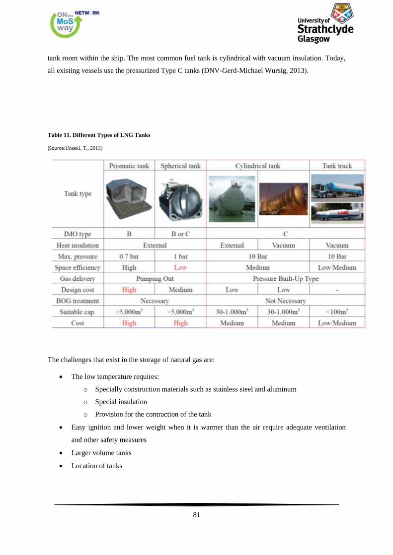
81
tank room within the ship. The most common fuel tank is cylindrical with vacuum insulation. Today,
all existing vessels use the pressurized Type C tanks (DNV-Gerd-Michael Wursig, 2013).
Table 11. Different Types of LNG Tanks
(Source:Unseki, T., 2013)
The challenges that exist in the storage of natural gas are:
The low temperature requires:
o Specially construction materials such as stainless steel and aluminum
o Special insulation
o Provision for the contraction of the tank
Easy ignition and lower weight when it is warmer than the air require adequate ventilation
and other safety measures
Larger volume tanks
Location of tanks
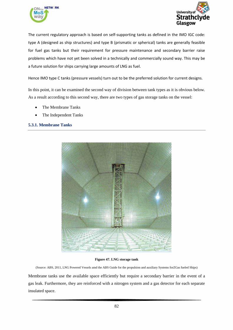
82
The current regulatory approach is based on self-supporting tanks as defined in the IMO IGC code:
type A (designed as ship structures) and type B (prismatic or spherical) tanks are generally feasible
for fuel gas tanks but their requirement for pressure maintenance and secondary barrier raise
problems which have not yet been solved in a technically and commercially sound way. This may be
a future solution for ships carrying large amounts of LNG as fuel.
Hence IMO type C tanks (pressure vessels) turn out to be the preferred solution for current designs.
In this point, it can be examined the second way of division between tank types as it is obvious below.
As a result according to this second way, there are two types of gas storage tanks on the vessel:
The Membrane Tanks
The Independent Tanks
5.3.1. Membrane Tanks
Figure 47. LNG storage tank
(Source: ABS, 2011, LNG Powered Vessels amd the ABS Guide for the propulsion and auxiliary Systems forZGas fueled Ships)
Membrane tanks use the available space efficiently but require a secondary barrier in the event of a
gas leak. Furthermore, they are reinforced with a nitrogen system and a gas detector for each separate
insulated space.
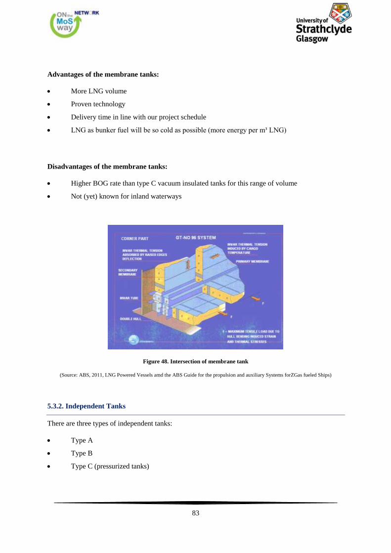
83
Advantages of the membrane tanks:
More LNG volume
Proven technology
Delivery time in line with our project schedule
LNG as bunker fuel will be so cold as possible (more energy per m³ LNG)
Disadvantages of the membrane tanks:
Higher BOG rate than type C vacuum insulated tanks for this range of volume
Not (yet) known for inland waterways
Figure 48. Intersection of membrane tank
(Source: ABS, 2011, LNG Powered Vessels amd the ABS Guide for the propulsion and auxiliary Systems forZGas fueled Ships)
5.3.2. Independent Tanks
There are three types of independent tanks:
Type A
Type B
Type C (pressurized tanks)
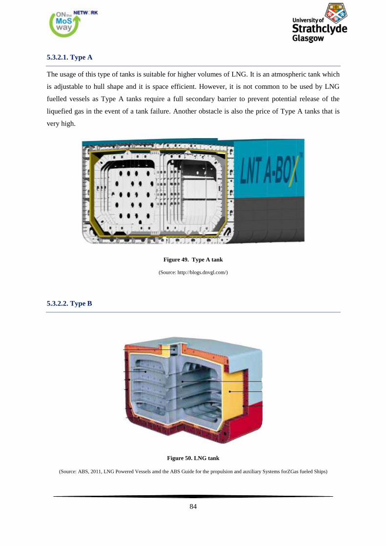
84
5.3.2.1. Type A
The usage of this type of tanks is suitable for higher volumes of LNG. It is an atmospheric tank which
is adjustable to hull shape and it is space efficient. However, it is not common to be used by LNG
fuelled vessels as Type A tanks require a full secondary barrier to prevent potential release of the
liquefied gas in the event of a tank failure. Another obstacle is also the price of Type A tanks that is
very high.
Figure 49. Type A tank
(Source: http://blogs.dnvgl.com/)
5.3.2.2. Type B
Figure 50. LNG tank
(Source: ABS, 2011, LNG Powered Vessels amd the ABS Guide for the propulsion and auxiliary Systems forZGas fueled Ships)
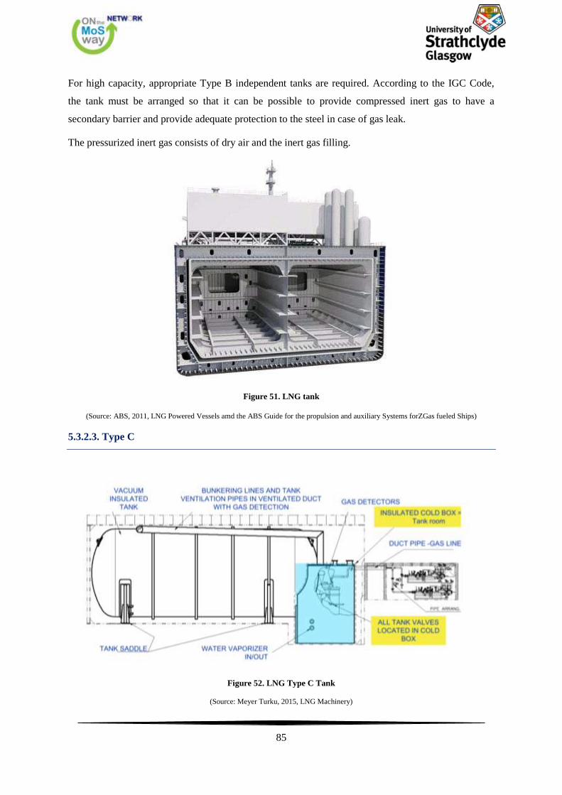
85
For high capacity, appropriate Type B independent tanks are required. According to the IGC Code,
the tank must be arranged so that it can be possible to provide compressed inert gas to have a
secondary barrier and provide adequate protection to the steel in case of gas leak.
The pressurized inert gas consists of dry air and the inert gas filling.
Figure 51. LNG tank
(Source: ABS, 2011, LNG Powered Vessels amd the ABS Guide for the propulsion and auxiliary Systems forZGas fueled Ships)
5.3.2.3. Type C
Figure 52. LNG Type C Tank
(Source: Meyer Turku, 2015, LNG Machinery)
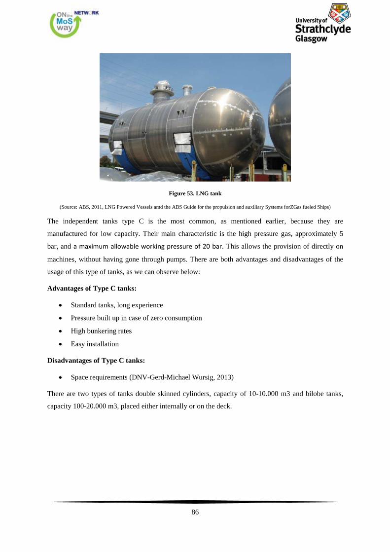
86
Figure 53. LNG tank
(Source: ABS, 2011, LNG Powered Vessels amd the ABS Guide for the propulsion and auxiliary Systems forZGas fueled Ships)
The independent tanks type C is the most common, as mentioned earlier, because they are
manufactured for low capacity. Their main characteristic is the high pressure gas, approximately 5
bar, and a maximum allowable working pressure of 20 bar. This allows the provision of directly on
machines, without having gone through pumps. There are both advantages and disadvantages of the
usage of this type of tanks, as we can observe below:
Advantages of Type C tanks:
Standard tanks, long experience
Pressure built up in case of zero consumption
High bunkering rates
Easy installation
Disadvantages of Type C tanks:
Space requirements (DNV-Gerd-Michael Wursig, 2013)
There are two types of tanks double skinned cylinders, capacity of 10-10.000 m3 and bilobe tanks,
capacity 100-20.000 m3, placed either internally or on the deck.

87
Figure 54. LNG double skinned tanks.
(Source: ABS, 2011, LNG Powered Vessels amd the ABS Guide for the propulsion and auxiliary Systems forZGas fueled Ships)
Figure 55. LNG bilobe tank.
(Source: ABS, 2011, LNG Powered Vessels amd the ABS Guide for the propulsion and auxiliary Systems forZGas fueled Ships)
5.3.3. Management of Boil-off Gas
A critical aspect of controlling methane leak emissions is the management of boil-off gas (BOG) from
the cryogenically cooled liquefied natural gas. At atmospheric pressure, natural gas must be
maintained at a temperature below –162°C in order to stay in a liquid state. It is therefore stored and
transported throughout the supply chain in specially designed, well-insulated containers. No matter
how well insulated, however, some heat will continually seep into the container. As heat is absorbed,
the head space pressure inside the container rises as LNG evaporates. The rate at which LNG
evaporates depends on the size of the tank and the materials and methods of construction.
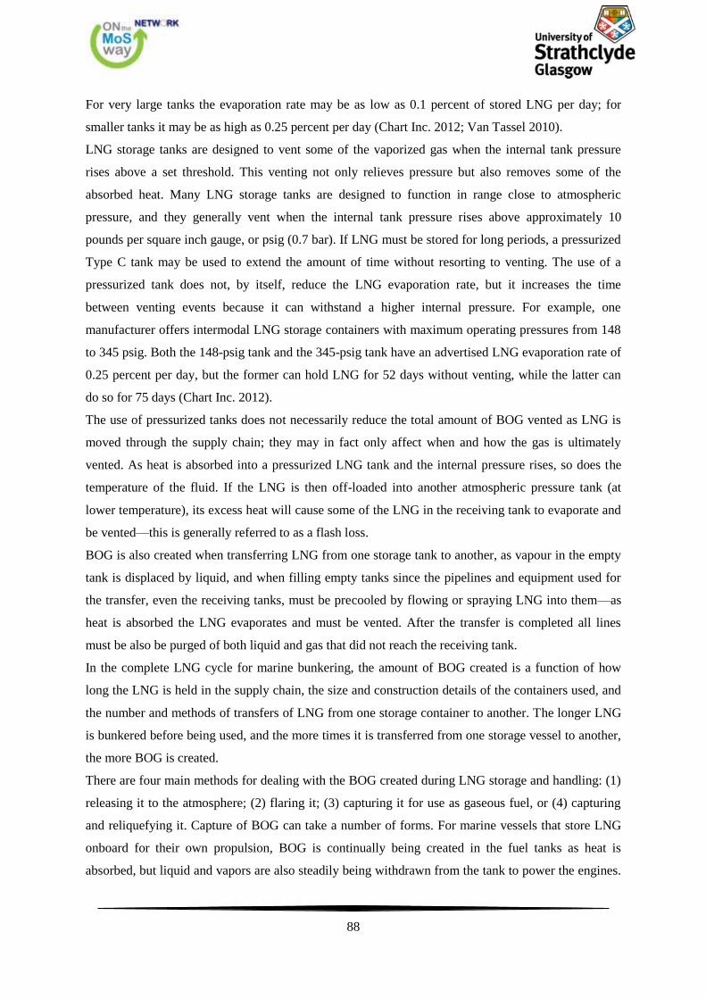
88
For very large tanks the evaporation rate may be as low as 0.1 percent of stored LNG per day; for
smaller tanks it may be as high as 0.25 percent per day (Chart Inc. 2012; Van Tassel 2010).
LNG storage tanks are designed to vent some of the vaporized gas when the internal tank pressure
rises above a set threshold. This venting not only relieves pressure but also removes some of the
absorbed heat. Many LNG storage tanks are designed to function in range close to atmospheric
pressure, and they generally vent when the internal tank pressure rises above approximately 10
pounds per square inch gauge, or psig (0.7 bar). If LNG must be stored for long periods, a pressurized
Type C tank may be used to extend the amount of time without resorting to venting. The use of a
pressurized tank does not, by itself, reduce the LNG evaporation rate, but it increases the time
between venting events because it can withstand a higher internal pressure. For example, one
manufacturer offers intermodal LNG storage containers with maximum operating pressures from 148
to 345 psig. Both the 148-psig tank and the 345-psig tank have an advertised LNG evaporation rate of
0.25 percent per day, but the former can hold LNG for 52 days without venting, while the latter can
do so for 75 days (Chart Inc. 2012).
The use of pressurized tanks does not necessarily reduce the total amount of BOG vented as LNG is
moved through the supply chain; they may in fact only affect when and how the gas is ultimately
vented. As heat is absorbed into a pressurized LNG tank and the internal pressure rises, so does the
temperature of the fluid. If the LNG is then off-loaded into another atmospheric pressure tank (at
lower temperature), its excess heat will cause some of the LNG in the receiving tank to evaporate and
be vented—this is generally referred to as a flash loss.
BOG is also created when transferring LNG from one storage tank to another, as vapour in the empty
tank is displaced by liquid, and when filling empty tanks since the pipelines and equipment used for
the transfer, even the receiving tanks, must be precooled by flowing or spraying LNG into them—as
heat is absorbed the LNG evaporates and must be vented. After the transfer is completed all lines
must be also be purged of both liquid and gas that did not reach the receiving tank.
In the complete LNG cycle for marine bunkering, the amount of BOG created is a function of how
long the LNG is held in the supply chain, the size and construction details of the containers used, and
the number and methods of transfers of LNG from one storage container to another. The longer LNG
is bunkered before being used, and the more times it is transferred from one storage vessel to another,
the more BOG is created.
There are four main methods for dealing with the BOG created during LNG storage and handling: (1)
releasing it to the atmosphere; (2) flaring it; (3) capturing it for use as gaseous fuel, or (4) capturing
and reliquefying it. Capture of BOG can take a number of forms. For marine vessels that store LNG
onboard for their own propulsion, BOG is continually being created in the fuel tanks as heat is
absorbed, but liquid and vapors are also steadily being withdrawn from the tank to power the engines.
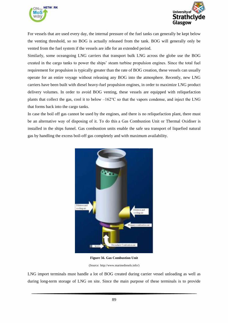
89
For vessels that are used every day, the internal pressure of the fuel tanks can generally be kept below
the venting threshold, so no BOG is actually released from the tank. BOG will generally only be
vented from the fuel system if the vessels are idle for an extended period.
Similarly, some oceangoing LNG carriers that transport bulk LNG across the globe use the BOG
created in the cargo tanks to power the ships’ steam turbine propulsion engines. Since the total fuel
requirement for propulsion is typically greater than the rate of BOG creation, these vessels can usually
operate for an entire voyage without releasing any BOG into the atmosphere. Recently, new LNG
carriers have been built with diesel heavy-fuel propulsion engines, in order to maximize LNG product
delivery volumes. In order to avoid BOG venting, these vessels are equipped with reliquefaction
plants that collect the gas, cool it to below –162°C so that the vapors condense, and inject the LNG
that forms back into the cargo tanks.
In case the boil off gas cannot be used by the engines, and there is no reliquefaction plant, there must
be an alternative way of disposing of it. To do this a Gas Combustion Unit or Thermal Oxidiser is
installed in the ships funnel. Gas combustion units enable the safe sea transport of liquefied natural
gas by handling the excess boil-off gas completely and with maximum availability.
Figure 56. Gas Combustion Unit
(Source: http://www.marinediesels.info/)
LNG import terminals must handle a lot of BOG created during carrier vessel unloading as well as
during long-term storage of LNG on site. Since the main purpose of these terminals is to provide
90
natural gas to grid, their normal procedure is to collect and compress the BOG vapors and inject them
into a natural gas pipeline. In some cases they might reliquefy a portion of the BOG and put it back
into storage rather than injecting the vapors into the gas grid, if economic conditions warrant. Import
terminals also typically maintain a flare in their BOG handling system in the event that instantaneous
BOG volume (i.e., flash losses) exceeds the compression or liquefaction capacity of the system.
Similarly, the BOG created during loading and unloading of trucks (primarily displaced vapor) that
transport LNG from an import terminal or liquefaction facility to satellite marine fuel cycle storage
facilities is typically directed to a low-pressure pipeline at the facility, for distribution to customers,
rather than being vented to the atmosphere.
LNG liquefaction plants can also collect BOG, compress it, and redirect it into the liquefaction
process to limit the amount of methane ultimately released into the atmosphere or flared. BOG
handling at remote marine bunkering sites is potentially more problematic. These sites are unlikely to
be connected to a natural gas pipeline that could be used to siphon the BOG created during tank
filling, long-term storage, or vessel fuelling. Reliquefaction could be considered to handle BOG at
these sites. However, the low average volume and intermittent nature of BOG generation would likely
make this method unattractive economically. For such locations, flaring might be the most practical
method to ensure that methane is not vented into the atmosphere.
Another option might be to co-locate LNG bunkering sites with compressed natural gas fuelling sites
for on-road vehicles as well as stationary power. Under such a scenario, BOG created from LNG
storage and fuelling operations could be compressed into on-site storage tanks for later delivery to
vehicles that run on compressed natural gas. BOG generated in LNG storage tanks and during vessel
fuelling could theoretically be used as well to satisfy on-site process heat or space heating needs, but
the practicality of such an approach would vary significantly from location to location. (Lowell, 2013)
For a 16,300 TEU container LNG fuelled vessel equipped with two membrane tanks capable of
bunkering up to 11,000 cubic metres (enough for approximately 15,000 nautical miles) one key issue
has been the treatment of boil-oil gas from the LNG tanks. The pressure increase inside the membrane
tank system, which is designed for a maximum of 700 mbarg, must be limited without releasing gas to
the atmosphere. This can be achieved by using the boil-off gas to power the auxiliary engines and the
boiler. This is a process that is developed more the last years, as mentioned above with the LNG
carriers.
Most of the time the power demand by far exceeds the natural boil-off from the tanks, so the system
must actually vaporise additional volumes of LNG to meet the fuel demand while maintaining a low
operating pressure inside the tanks (typically between 50 and 300 mbarg). However, when the ship is
idle (at anchorage for instance) and the power demand is very low, gas pressure will build up inside
the tank. As long as some gas is drawn to power the minimum hotel load, the pressure will increase
91
relatively slowly. Should the pressure inside the tanks exceed a preset value (around 600 mbarg) – a
case not foreseen in the operating profile envisioned for the ship – the excess boil-off will be directed
to the boiler (as a gas combusting unit) for incineration. For operating proiles including longer idle
periods, a Mark III Flex membrane system could be used, which would provide 50 percent more time
for the pressure to reach the GCU threshold. A Mark III Flex membrane has 400 millimetres of PU
foam insulation versus 270 millimetres in a standard Mark III system. (DNV GL, 2014)
5.3.4. LNG Tank Location
Of the two possibilities, above or below deck, the above deck location is less complex and less
expensive. The below deck location requires zoned separation from other spaces, explosion proof
appliance, dedicated ventilation systems and, in general, more controls. LNG tank storage cannot be
placed where MDO can be stored (wing tanks, DB’s) and thus the volume requirements are many
times that of storing MDO. On the other hand, above deck locations, well away from the vessels roll
and pitch centers, invite greater sloshing and possibly greater structural weight in the installation. The
location in the length of the vessel could be impacted by cargo considerations as discussed later.
The tanks that will be installed on open deck have the following limitations.
• Have B/5 distance from the hull as mentioned earlier. In ships not carrying passengers, the
tanks can be placed closer to the edge of the deck. This depends on the volume of the tank and ranged
from 0.8-2.0 m but never less than 800mm.
• To be located in a place where there is adequate natural ventilation
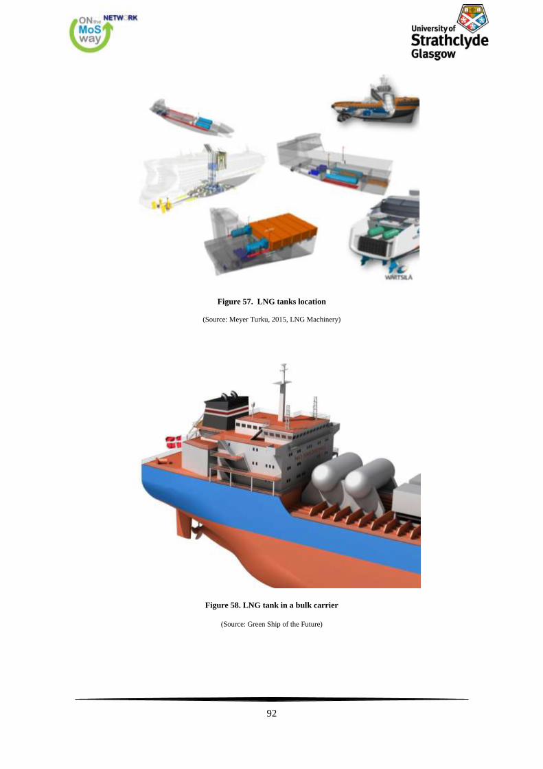
92
Figure 57. LNG tanks location
(Source: Meyer Turku, 2015, LNG Machinery)
Figure 58. LNG tank in a bulk carrier
(Source: Green Ship of the Future)
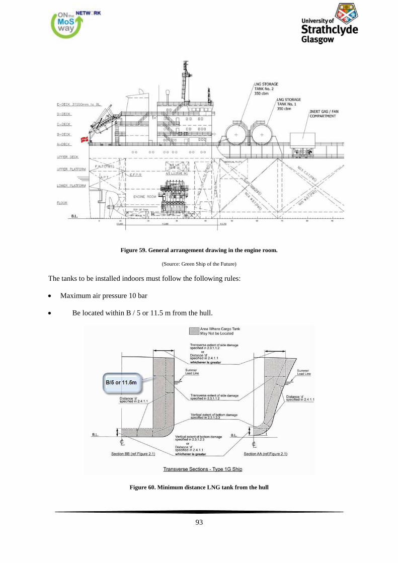
93
Figure 59. General arrangement drawing in the engine room.
(Source: Green Ship of the Future)
Τhe tanks to be installed indoors must follow the following rules:
Maximum air pressure 10 bar
Be located within B / 5 or 11.5 m from the hull.
Figure 60. Minimum distance LNG tank from the hull
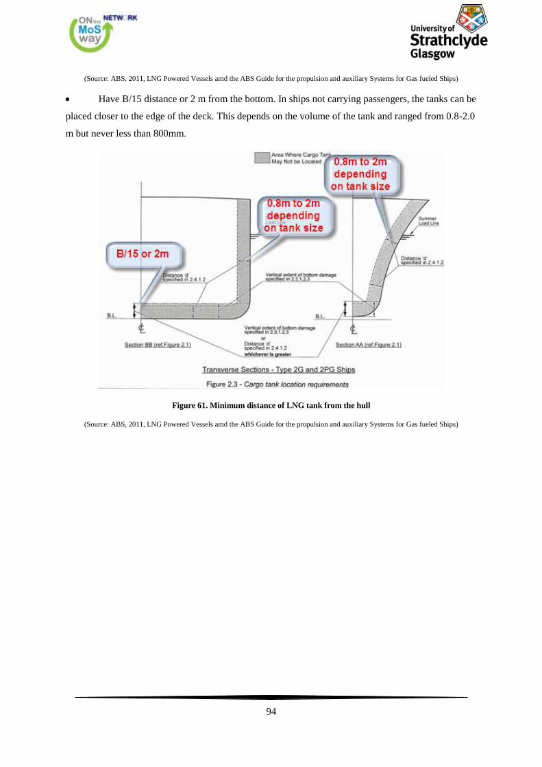
94
(Source: ABS, 2011, LNG Powered Vessels amd the ABS Guide for the propulsion and auxiliary Systems for Gas fueled Ships)
Have B/15 distance or 2 m from the bottom. In ships not carrying passengers, the tanks can be
placed closer to the edge of the deck. This depends on the volume of the tank and ranged from 0.8-2.0
m but never less than 800mm.
Figure 61. Minimum distance of LNG tank from the hull
(Source: ABS, 2011, LNG Powered Vessels amd the ABS Guide for the propulsion and auxiliary Systems for Gas fueled Ships)
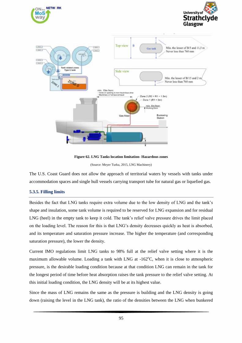
95
Figure 62. LNG Tanks location limitation- Hazardous zones
(Source: Meyer Turku, 2015, LNG Machinery)
The U.S. Coast Guard does not allow the approach of territorial waters by vessels with tanks under
accommodation spaces and single hull vessels carrying transport tube for natural gas or liquefied gas.
5.3.5. Filling limits
Besides the fact that LNG tanks require extra volume due to the low density of LNG and the tank’s
shape and insulation, some tank volume is required to be reserved for LNG expansion and for residual
LNG (heel) in the empty tank to keep it cold. The tank’s relief valve pressure drives the limit placed
on the loading level. The reason for this is that LNG’s density decreases quickly as heat is absorbed,
and its temperature and saturation pressure increase. The higher the temperature (and corresponding
saturation pressure), the lower the density.
Current IMO regulations limit LNG tanks to 98% full at the relief valve setting where it is the
maximum allowable volume. Loading a tank with LNG at -162oC, when it is close to atmospheric
pressure, is the desirable loading condition because at that condition LNG can remain in the tank for
the longest period of time before heat absorption raises the tank pressure to the relief valve setting. At
this initial loading condition, the LNG density will be at its highest value.
Since the mass of LNG remains the same as the pressure is building and the LNG density is going
down (raising the level in the LNG tank), the ratio of the densities between the LNG when bunkered
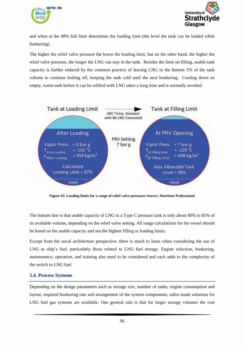
96
and when at the 98% full limit determines the loading limit (the level the tank can be loaded while
bunkering).
The higher the relief valve pressure the lower the loading limit, but on the other hand, the higher the
relief valve pressure, the longer the LNG can stay in the tank. Besides the limit on filling, usable tank
capacity is further reduced by the common practice of leaving LNG in the bottom 5% of the tank
volume to continue boiling off, keeping the tank cold until the next bunkering. Cooling down an
empty, warm tank before it can be refilled with LNG takes a long time and is normally avoided.
Figure 63. Loading limits for a range of relief valve pressures Source: Maritime Professional
The bottom line is that usable capacity of LNG in a Type C pressure tank is only about 80% to 85% of
its available volume, depending on the relief valve setting. All range calculations for the vessel should
be based on the usable capacity and not the highest filling or loading limits.
Except from the naval architecture perspective, there is much to learn when considering the use of
LNG as ship’s fuel, particularly those related to LNG fuel storage. Engine selection, bunkering,
maintenance, operation, and training also need to be considered and each adds to the complexity of
the switch to LNG fuel.
5.4. Process Systems
Depending on the design parameters such as storage size, number of tanks, engine consumption and
layout, required bunkering rate and arrangement of the system components, tailor-made solutions for
LNG fuel gas systems are available. One general rule is that for larger storage volumes the cost
97
impact of high tank operating pressures becomes significant; these systems should be preferably
equipped with mechanical pressure rising (pumps, compressors) instead of keeping the entire tank on
supply pressure level. Smaller tanks can be pressurized to the required gas supply pressure. The cost
impact of the higher tank design pressure is fairly small and there is a benefit of easy operation and
reduced numbers of rotating equipment. When using vacuum insulated tanks, a bottom outlet will
feed a tank vaporizer just forced by density (see figure 64). Typically the operation pressure would be
around 7 bar g. By means of the tank pressure the LNG is pushed towards the LNG vaporizer. Usually
all tank connections and the tank vaporizer are enclosed in a “cold box” as a secondary barrier. A fuel
gas heater will be employed in order to provide vapour at the right temperature via fuel gas master
valve to gas valve unit (GVU). The GVU reduces pressure to the required value of the engines and is
usually part of the engine manufacturer’s supply.
Figure 64. Schematic diagram of fuel gas system with vacuum tank and cold box
(Source: Harperscheidt, J. 2011, Bunkering, infrastructure, storage, and processing of LNG)
One option for this simple system is to use a small in-tank pump to feed the tank vaporizer, thus
avoiding the bottom outlet. However, this is only possible for single shell type C tanks with foam
insulation. As mentioned above, when using larger tank volumes high design pressure will increase
the cost significantly. Including a screw compressor in order to pressurize the fuel gas is one option to
reduce design pressure from typically 10 barg to 4 barg, see figure 65. Vaporization will then take
place at a lower pressure level, a small amount of pressurized vapour is returned to the tank to push
the liquid to the vaporizer. The compressor system also allows for other operations like fuel gas
supply from tank vapour phase, warming-up of the piping system and tanks with hot gas and
increasing loading rate without vapour return using a BOG absorber.
98
Figure 65. Schematic diagram of fuel gas system with compressor
(Source: Harperscheidt, J. 2011, Bunkering, infrastructure, storage, and processing of LNG)
Two stroke engines require another modification of the system due to high injection pressure of 300
bar g, see figure 66. On LNG carriers this can be achieved by using BOG compressors but for other
ships, this will only be a viable solution in some particular cases due to high CAPEX, power
requirements, size and weight of such equipment. High pressure pumps and high pressure vaporizer
and heater are the preferred alternative in order to achieve the required pressure level. Tanks will
usually be equipped with small in-tank pumps or pressure built-up vaporizers to feed the high pressure
system.
99
Figure 66.Schematic diagram of high pressure fuel gas system for two-stroke engines
(Source: Harperscheidt, J. 2011, Bunkering, infrastructure, storage, and processing of LNG)
At this point it would be very helpful to present the process system of an LNG carrier equipped with
dual fuel engines. The principle of the plant is outlined at the figure below. The gas boil off is
pressurized to about 5.5 bar by compressors and is then heated to about 30°C. The gas is then piped to
the engines, where it is injected into the intake air before the air enters the cylinders. Ignition is by
pilot injection of diesel fuel.
Figure 67. Layout of Dual Fuel engines system of an LNG carrier
(Source: http://www.marinediesels.info/)
100
5.5. Engine, LNG Storage and Security Systems Layout
In this chapter, we will discuss briefly the main changes to be made in order to use LNG as fuel
instead of HFO.
Figure 68. Engine room diagram
(Source: ABS, 2011, LNG Powered Vessels amd the ABS Guide for the propulsion and auxiliary Systems for Gas fueled Ships)
The figure above shows the main parts of the engine room of a ship running on LNG. We can observe
ventilation ducts and air flow channels in the machinery, fire and gas detectors and double walled
pipes. In these tubes, there is space containing pressurized inert gas at a pressure higher than that of
the gas. In case of loss of pressure of the inert gas due to leakage of gas safety systems are actuated.
Furthermore, the shape looks the GVU (Gas Valve Unit) room. GVU is a module located between the
LNG storage system and the dual-fuel (DF) engine. The GVU room is a very important part of the
installation and regulates the pressure of the gas and ensures timely and reliable deactivation of the
gas supply system.
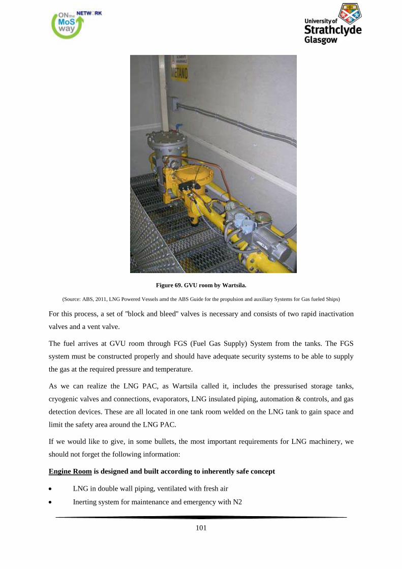
101
Figure 69. GVU room by Wartsila.
(Source: ABS, 2011, LNG Powered Vessels amd the ABS Guide for the propulsion and auxiliary Systems for Gas fueled Ships)
For this process, a set of ''block and bleed'' valves is necessary and consists of two rapid inactivation
valves and a vent valve.
The fuel arrives at GVU room through FGS (Fuel Gas Supply) System from the tanks. The FGS
system must be constructed properly and should have adequate security systems to be able to supply
the gas at the required pressure and temperature.
As we can realize the LNG PAC, as Wartsila called it, includes the pressurised storage tanks,
cryogenic valves and connections, evaporators, LNG insulated piping, automation & controls, and gas
detection devices. These are all located in one tank room welded on the LNG tank to gain space and
limit the safety area around the LNG PAC.
If we would like to give, in some bullets, the most important requirements for LNG machinery, we
should not forget the following information:
Engine Room is designed and built according to inherently safe concept
LNG in double wall piping, ventilated with fresh air
Inerting system for maintenance and emergency with N2

102
Normal ventilation in engine room
Normal equipment in engine room
Exhaust piping burst discs
Normal fire fighting
Fuel Gas Supply System
From Tank to tank room (‘cold box’) in liquid form
LNG gasification with heat from LT-circuit
Heat from AC-system, ‘cold recovery’
From tank room to GVUs in gaseous form
Double walled from tank room to Gas Valve
Units (GVU)
Tank room controls the pressure and
temperature according to need
From GVUs to engines and boilers
Gas Valve Unit can be located in a room or be built into a module
GVU distance to engines limitation, max 10 meters
GVU regulates the gas pressure to the engine according to engine load
Boiler GVU regulates the gas pressure to boiler
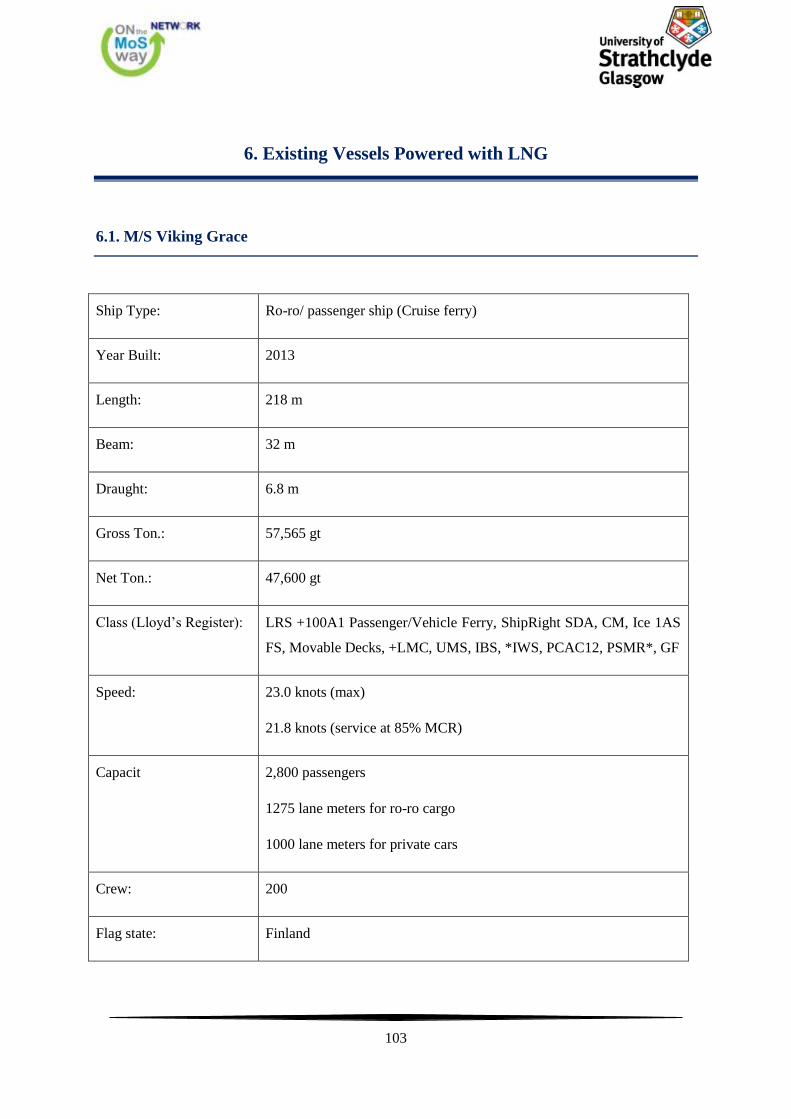
103
6. Existing Vessels Powered with LNG
6.1. M/S Viking Grace
Ship Type: Ro-ro/ passenger ship (Cruise ferry)
Year Built: 2013
Length: 218 m
Beam: 32 m
Draught: 6.8 m
Gross Ton.: 57,565 gt
Net Ton.: 47,600 gt
Class (Lloyd’s Register): LRS +100A1 Passenger/Vehicle Ferry, ShipRight SDA, CM, Ice 1AS
FS, Movable Decks, +LMC, UMS, IBS, *IWS, PCAC12, PSMR*, GF
Speed: 23.0 knots (max)
21.8 knots (service at 85% MCR)
Capacit 2,800 passengers
1275 lane meters for ro-ro cargo
1000 lane meters for private cars
Crew: 200
Flag state: Finland
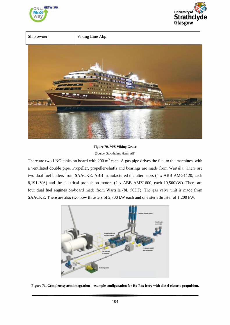
104
Ship owner: Viking Line Abp
Figure 70. M/S Viking Grace
(Source: Stockholms Hamn AB)
There are two LNG tanks on board with 200 m3 each. A gas pipe drives the fuel to the machines, with
a ventilated double pipe. Propeller, propeller-shafts and bearings are made from Wärtsilä. There are
two dual fuel boilers from SAACKE. ABB manufactured the alternators (4 x ABB AMG1120, each
8,191kVA) and the electrical propulsion motors (2 x ABB AMZ1600, each 10,500kW). There are
four dual fuel engines on-board made from Wärtsilä (8L 50DF). The gas valve unit is made from
SAACKE. There are also two bow thrusters of 2,300 kW each and one stern thruster of 1,200 kW.
Figure 71. Complete system integration – example configuration for Ro-Pax ferry with diesel-electric propulsion.
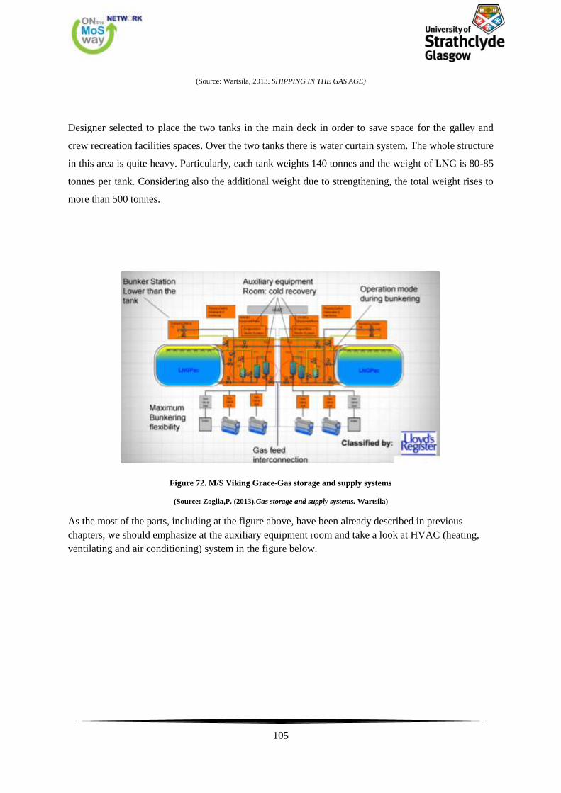
105
(Source: Wartsila, 2013. SHIPPING IN THE GAS AGE)
Designer selected to place the two tanks in the main deck in order to save space for the galley and
crew recreation facilities spaces. Over the two tanks there is water curtain system. The whole structure
in this area is quite heavy. Particularly, each tank weights 140 tonnes and the weight of LNG is 80-85
tonnes per tank. Considering also the additional weight due to strengthening, the total weight rises to
more than 500 tonnes.
Figure 72. M/S Viking Grace-Gas storage and supply systems
(Source: Zoglia,P. (2013).Gas storage and supply systems. Wartsila)
As the most of the parts, including at the figure above, have been already described in previous
chapters, we should emphasize at the auxiliary equipment room and take a look at HVAC (heating,
ventilating and air conditioning) system in the figure below.
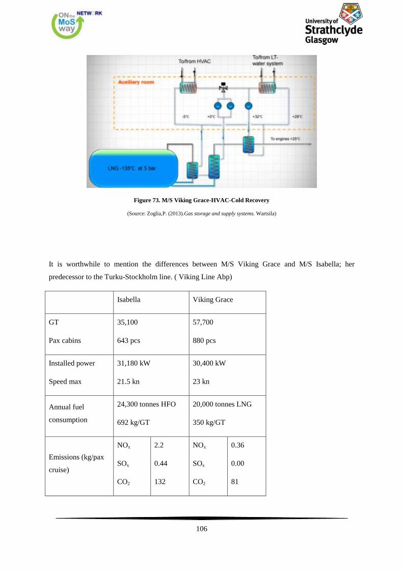
106
Figure 73. M/S Viking Grace-HVAC-Cold Recovery
(Source: Zoglia,P. (2013).Gas storage and supply systems. Wartsila)
It is worthwhile to mention the differences between M/S Viking Grace and M/S Isabella; her
predecessor to the Turku-Stockholm line. ( Viking Line Abp)
Isabella Viking Grace
GT
Pax cabins
35,100
643 pcs
57,700
880 pcs
Installed power
Speed max
31,180 kW
21.5 kn
30,400 kW
23 kn
Annual fuel
consumption
24,300 tonnes HFO
692 kg/GT
20,000 tonnes LNG
350 kg/GT
Emissions (kg/pax
cruise)
NOx
SOx
CO2
2.2
0.44
132
NOx
SOx
CO2
0.36
0.00
81
107
PM 0.088 PM 0.001
6.2. Case Study: Hamworthy Baltic Design Centre, Project No. 3103
Main particulars:
Length overall 193.20 m
Length between perp. 175.00 m
Breadth moulded 28.50 m
Depth to entrance 10.60 m
Depth to upper deck 23.30 m
Design draught 6.80 m
Scantling draught 7.00 m
Max. deadweight 9800 t
Lane length (2.90m width) 2400 sqm
Cruising range:
Only on LNG 3500 Nm
Only on MDO 3200 Nm
LNG and MDO 6200 Nm
Main engines are made from Wartsila (4 x 9L50DF) and the nominal output is 34,200 kW. There are
two controllable pitch propellers fitted. Service speed (90% MCR, 15% SM, PTO-off) is 22.5 knots.

108
Class:
Det Norske Veritas +1A1 ’Car Ferry’, gas fuelled, ICE 1A, E0, NAUT-OC, RP, LCS-DC, clean
design, BWM-TP, TMON.
Tank capacities (m3):
Liquefied natural gas 1500
Marine diesel oil 780
Lubricating oil 220
Fresh/technical water 1200
Passengers 400
Crew 86
Hamworthy Project No. 3103, source Hamworthy
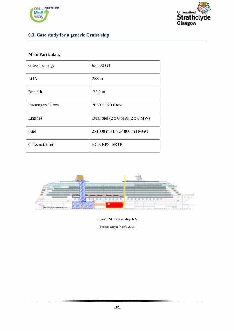
109
6.3. Case study for a generic Cruise ship
Main Particulars
Gross Tonnage 63,000 GT
LOA 238 m
Breadth 32.2 m
Passengers/ Crew 2050 + 570 Crew
Engines Dual fuel (2 x 6 MW; 2 x 8 MW)
Fuel 2x1000 m3 LNG/ 800 m3 MGO
Class notation EC0, RPS, SRTP
Figure 74. Cruise ship GA
(Source: Meyer Werft, 2013)
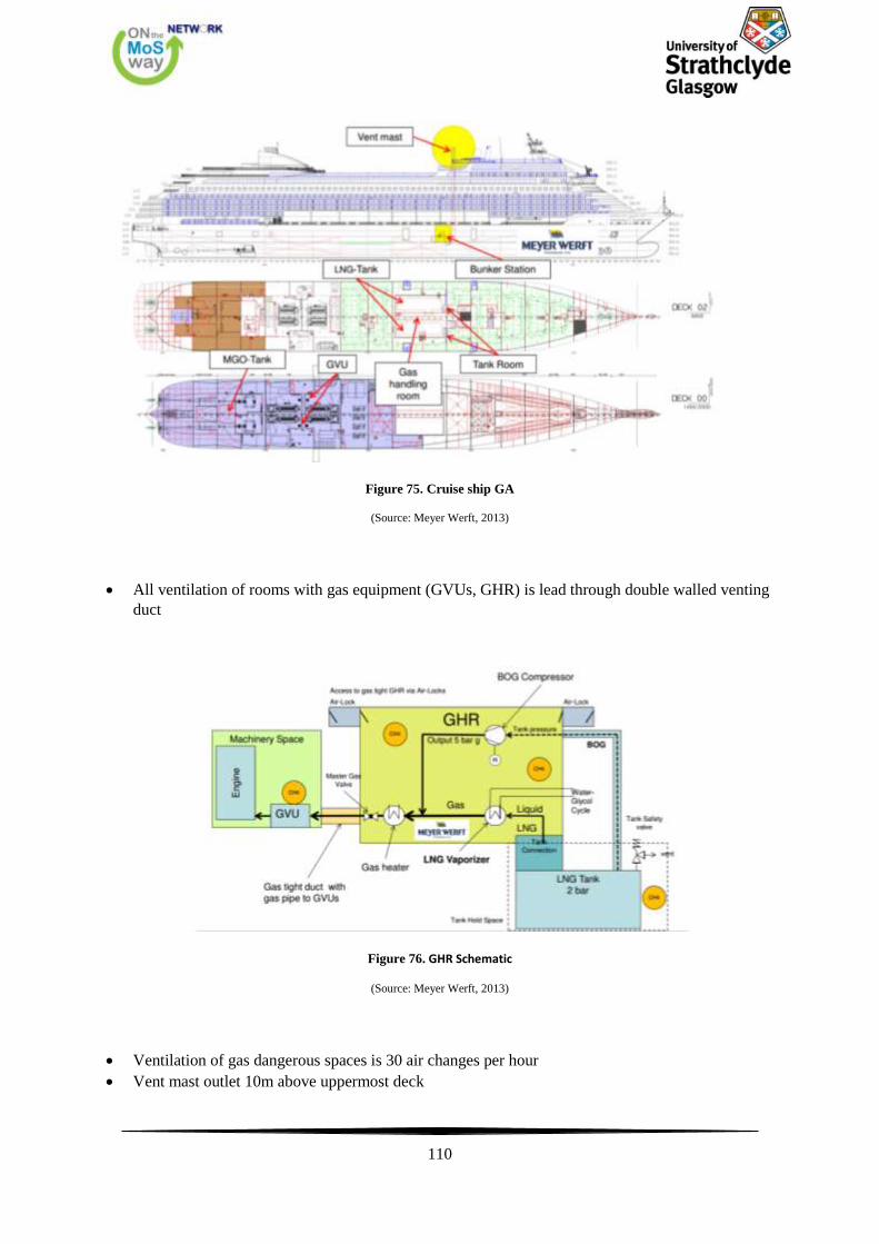
110
Figure 75. Cruise ship GA
(Source: Meyer Werft, 2013)
All ventilation of rooms with gas equipment (GVUs, GHR) is lead through double walled venting
duct
Figure 76. GHR Schematic
(Source: Meyer Werft, 2013)
Ventilation of gas dangerous spaces is 30 air changes per hour
Vent mast outlet 10m above uppermost deck

111
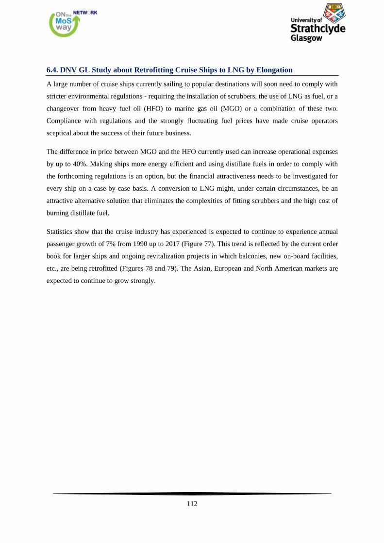
112
6.4. DNV GL Study about Retrofitting Cruise Ships to LNG by Elongation
A large number of cruise ships currently sailing to popular destinations will soon need to comply with
stricter environmental regulations - requiring the installation of scrubbers, the use of LNG as fuel, or a
changeover from heavy fuel oil (HFO) to marine gas oil (MGO) or a combination of these two.
Compliance with regulations and the strongly fluctuating fuel prices have made cruise operators
sceptical about the success of their future business.
The difference in price between MGO and the HFO currently used can increase operational expenses
by up to 40%. Making ships more energy efficient and using distillate fuels in order to comply with
the forthcoming regulations is an option, but the financial attractiveness needs to be investigated for
every ship on a case-by-case basis. A conversion to LNG might, under certain circumstances, be an
attractive alternative solution that eliminates the complexities of fitting scrubbers and the high cost of
burning distillate fuel.
Statistics show that the cruise industry has experienced is expected to continue to experience annual
passenger growth of 7% from 1990 up to 2017 (Figure 77). This trend is reflected by the current order
book for larger ships and ongoing revitalization projects in which balconies, new on-board facilities,
etc., are being retrofitted (Figures 78 and 79). The Asian, European and North American markets are
expected to continue to grow strongly.

113
Figure 77. Growth of worldwide passengers carried.
(Source: cruisemarketwatch.com)
The future of cruising continues to look promising and the industry has a large growth potential,
provided it continues to compete price-wise with the alternative options. Currently, 299 cruise ships
are in operation. Figures 78 and 79 show that there is a large number of ships below 40,000 GT with
an age of almost 26 years. Moving up to larger ships, a clear drop in age can be seen, with the average
age falling almost to six years for ships larger than 143,000 GT. In addition, the current order book
also supports the fact that the industry is continuing to move towards larger ships (Figure 2).
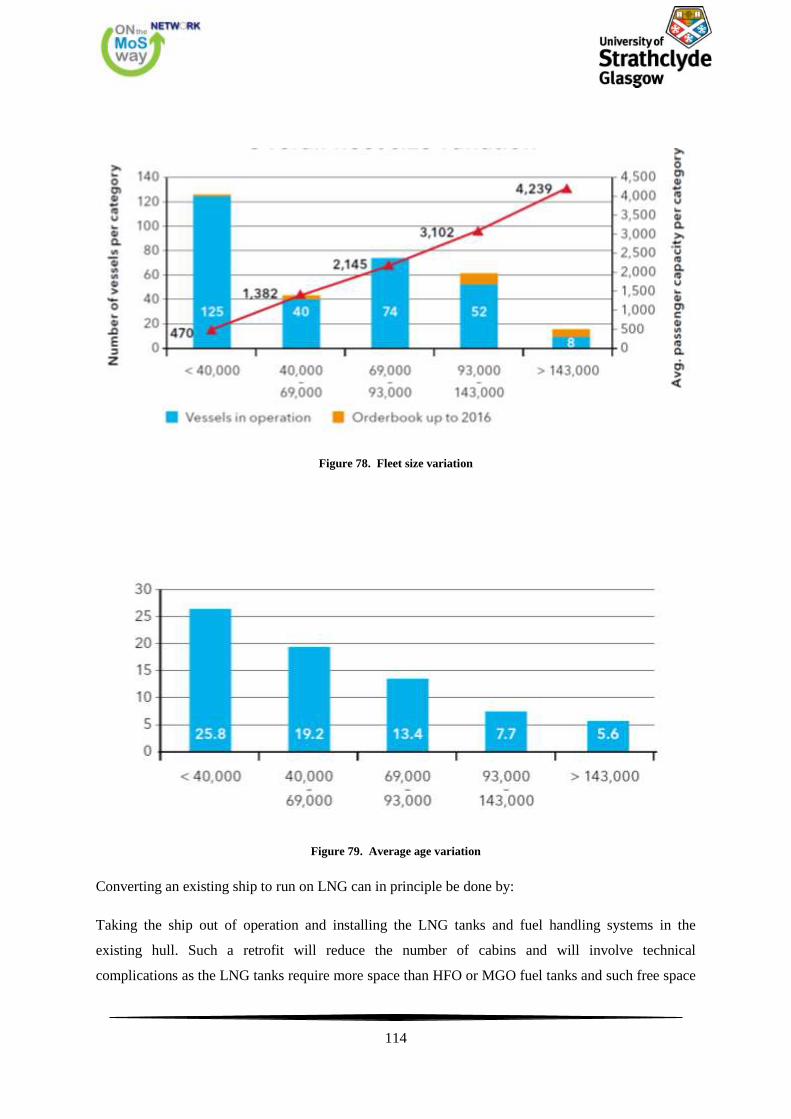
114
Figure 78. Fleet size variation
Figure 79. Average age variation
Converting an existing ship to run on LNG can in principle be done by:
Taking the ship out of operation and installing the LNG tanks and fuel handling systems in the
existing hull. Such a retrofit will reduce the number of cabins and will involve technical
complications as the LNG tanks require more space than HFO or MGO fuel tanks and such free space
115
is not available on the ship. In addition, this is time-consuming and thus represents a loss of revenue
due to the lengthy off-hire.
Inserting a new “LNG Ready” prefabricated mid-body section containing all the LNG systems,
additional cabins and public spaces into the ship. Such a retrofit can be done in a few weeks, the ship
does not need to go on a lengthy off-hire and the passenger capacity will increase by approximately
10%. The investment is limited to approximately 10% to 12% of new building costs.
In this study, we focus on the second option, which is proven to be the most feasible solution from a
technical and financial perspective.
The potentially strongest candidates for conversion comprise 8-19-year-old ships between 40,000 GT
and 143,000 GT which represent almost 55% of the fleet. Ships over 143,000 GT have been excluded
as their length is already at the limit of present port capacities.
Ships below 40,000 GT are not considered favourable for lengthening due to the limitations of the
ports they visit. Cruise ships of this size are usually in the luxury segment, typically visiting smaller
and less busy ports without the infrastructure and ability to receive the bigger ships. Another reason is
the lack of financial attractiveness; the payback time of the investment is increased due to the lower
passenger capacity. However, because these are high-end ships, the investment cost could be absorbed
by the higher premiums.
Generally, every ship has unique characteristics and whether or not it is a good candidate for
conversion needs to be investigated on a case-by–case basis and in close cooperation with the
respective flag state administrations.
Technical considerations
The ‘crazy idea’ outlined in the title involves the conversion of a cruise ship to run on LNG by
lengthening it (Figure 4). A new prefabricated part, containing LNG tanks and all the required LNG
systems, is added to the ship.
As mentioned earlier, every ship is different – so whether or not it can be converted must be
extensively assessed. In the following part, all the required technical modifications are outlined and
presented from a hull and structural perspective, the machinery point of view and finally the
operational side.
Benefits
Most likely improved revenue
116
Increased number of passenger and crew cabins
Improved environmental footprint
Energy efficiency may be increased by installing low-improving appendages during dry-docking
Additional public space and retail capacity
Additional open deck spaces
Reduction of main engine maintenance hours
Less engine crew required
Cheaper lubricants
Cleaner engine room
No soot on decks – less cleaning and wash water needed
No need for exhaust cleaning devices or catalytic reactors
Slightly lower noise level in engine room
Current challenges
Design & retrofit cost compared to switching to distillates
Time required for ship to be taken out of service for the retrofit operations
Elongation may reduce the range of ports of call
Bunkering challenges
Statutory challenges
LNG fuel cost pricing challenges
LNG infrastructure challenges
More tank space required to accommodate enough LNG to cover all the itineraries
Onshore bunkering logistics are still under development
Rules still under development
More sophisticated fuel equipment is required
Public perception not fully known
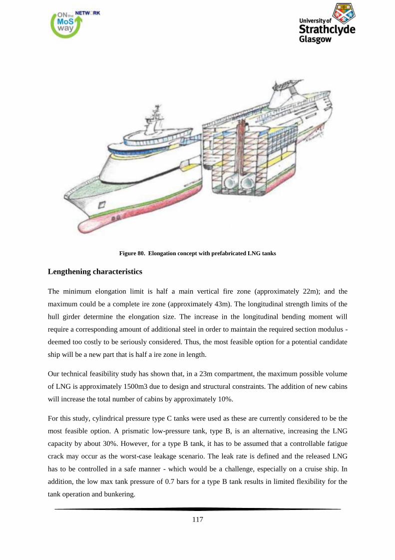
117
Figure 80. Elongation concept with prefabricated LNG tanks
Lengthening characteristics
The minimum elongation limit is half a main vertical fire zone (approximately 22m); and the
maximum could be a complete ire zone (approximately 43m). The longitudinal strength limits of the
hull girder determine the elongation size. The increase in the longitudinal bending moment will
require a corresponding amount of additional steel in order to maintain the required section modulus -
deemed too costly to be seriously considered. Thus, the most feasible option for a potential candidate
ship will be a new part that is half a ire zone in length.
Our technical feasibility study has shown that, in a 23m compartment, the maximum possible volume
of LNG is approximately 1500m3 due to design and structural constraints. The addition of new cabins
will increase the total number of cabins by approximately 10%.
For this study, cylindrical pressure type C tanks were used as these are currently considered to be the
most feasible option. A prismatic low-pressure tank, type B, is an alternative, increasing the LNG
capacity by about 30%. However, for a type B tank, it has to be assumed that a controllable fatigue
crack may occur as the worst-case leakage scenario. The leak rate is defined and the released LNG
has to be controlled in a safe manner - which would be a challenge, especially on a cruise ship. In
addition, the low max tank pressure of 0.7 bars for a type B tank results in limited flexibility for the
tank operation and bunkering.
118
A high-level study showed that, with 1,500m3 of LNG, approximately 70%-80% of all existing cruise
itineraries can be operated. In order to cover the remaining routes, which are longer and require more
fuel, the operator can either use the ship’s dual-fuel capabilities and burn MGO/HFO, depending on
the location, or perform a second bunkering operation to fill up with LNG half way through the
voyage. A potential new mid-body section of 43m will be able to accommodate approximately
3,000m3 of LNG in total and this will enable the ship to carry out all the current itineraries.
Flag engagement
Before deciding on a conversion, it is of the utmost importance to involve the Flag State
Administration at an early stage, since a lengthening is defined as a major conversion. The new part of
the ship must comply with the SOLAS regulation that is applicable when the conversion starts.
According to SOLAS II-2/1.3.2,“Repairs, alterations and modifications which substantially alter the
dimensions of a ship …shall meet the requirements for ships constructed on or after 1 July 2012 in so
far as the Administration deems reasonable and practicable”. Although the term ‘substantially’ is not
defined, a ship elongation operation is considered to be a major conversion as it alters the ship’s initial
dimensions. Therefore, the involvement of the Flag is even more important. Finally, the damage
stability regulations to be applied need to be clarified at an early stage.
Current SOLAS requirements include the Safe Return to Port (SRtP) requirements, which should be
complied with as well. However, as SRtP is a design requirement and applies to the whole ship,
achieving compliance with a pre-2012 ship is a significant challenge. The Flag should therefore be
contacted in order to obtain an exemption from the SRtP requirements.
Hull and structure
The following steps are required for the hull and structural part of the conversion:
The longitudinal strength of the candidate ship has to be evaluated. The maximum allowable
bending moment can become a showstopper if the hull is already designed to its optimum and
cannot sustain any additional length
A damage stability study needs to be performed in order to determine the location of the new part
Fire boundaries and the evacuation arrangements need to be sorted out when planning the inserted
arrangement
Machinery spaces need to be appraised and re-arranged as necessary
The location of the bunker station might create some challenges as balconies, openings and
lifeboats cannot be within a safety distance of the bunker station
119
The location of the vent mast needs to be considered in order to avoid disruptions on the upper
decks
Operational requirements
A major nautical aspect that needs to be investigated is the slow speed manoeuvring capability in
port of the now longer ship
The addition of new cabins requires an increase in potable black and grey water capacity
Machinery requirements
The possibility of converting the main engines to dual-fuel needs to be investigated. Engine
suppliers are continuously developing retrofit packages for different engine types
A longer ship will also require an increased thruster capacity. New bow and stern thrusters might
be necessary
The ship’s power supply will need to be recalculated due to the increased hotel load. On the plus-
side, exploiting the properties of LNG such as utilising LNG cold recovery for cooling and a
higher waste heat recovery potential, both of which make the engine room more energy efficient,
might balance out the need for additional hotel power
Removing the ship’s entire HFO capability, including fuel treatment systems and tanks, could
also be investigated. This will free up space in the engine rooms for new LNG tanks. However,
this will leave the ship with MGO as its second fuel and thus have a slight effect on the fuel cost
if MGO is consumed instead of HFO
Cutting the ship in half involves severing and splicing all the coordination systems, including
cables, pipes and ducts. This is a job not to be underestimated
Financial assessment
The investment cost required for such a conversion can be broken down into different categories. In
addition to the cost of the systems outlined below, the cost of having the ship off-hire needs to be
taken into consideration. On the other hand, there is a reduction in the yearly operational expenses
outlined below and an additional increase in revenue and profit from the larger number of cabins.
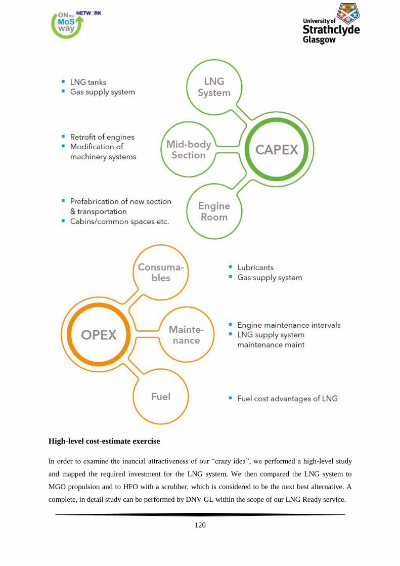
120
High-level cost-estimate exercise
In order to examine the inancial attractiveness of our “crazy idea”, we performed a high-level study
and mapped the required investment for the LNG system. We then compared the LNG system to
MGO propulsion and to HFO with a scrubber, which is considered to be the next best alternative. A
complete, in detail study can be performed by DNV GL within the scope of our LNG Ready service.
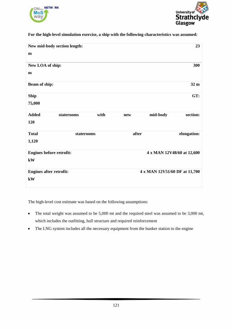
121
For the high-level simulation exercise, a ship with the following characteristics was assumed:
New mid-body section length: 23
m
New LOA of ship: 300
m
Beam of ship: 32 m
Ship GT:
75,000
Added staterooms with new mid-body section:
120
Total staterooms after elongation:
1,120
Engines before retrofit: 4 x MAN 12V48/60 at 12,600
kW
Engines after retrofit: 4 x MAN 12V51/60 DF at 11,700
kW
The high-level cost estimate was based on the following assumptions:
The total weight was assumed to be 5,000 mt and the required steel was assumed to be 3,000 mt,
which includes the outfitting, hull structure and required reinforcement
The LNG system includes all the necessary equipment from the bunker station to the engine
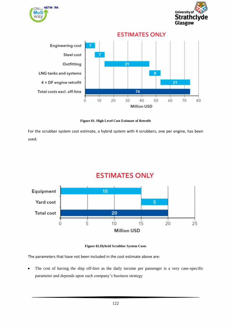
122
Figure 81. High Level Cost Estimate of Retrofit
For the scrubber system cost estimate, a hybrid system with 4 scrubbers, one per engine, has been
used.
Figure 82.Hybrid Scrubber System Costs
The parameters that have not been included in the cost estimate above are:
The cost of having the ship off-hire as the daily income per passenger is a very case-specific
parameter and depends upon each company’s business strategy
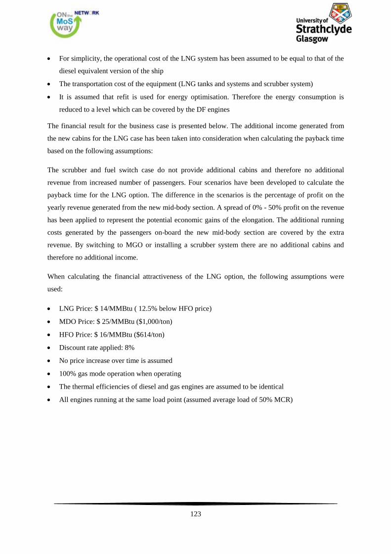
123
For simplicity, the operational cost of the LNG system has been assumed to be equal to that of the
diesel equivalent version of the ship
The transportation cost of the equipment (LNG tanks and systems and scrubber system)
It is assumed that refit is used for energy optimisation. Therefore the energy consumption is
reduced to a level which can be covered by the DF engines
The financial result for the business case is presented below. The additional income generated from
the new cabins for the LNG case has been taken into consideration when calculating the payback time
based on the following assumptions:
The scrubber and fuel switch case do not provide additional cabins and therefore no additional
revenue from increased number of passengers. Four scenarios have been developed to calculate the
payback time for the LNG option. The difference in the scenarios is the percentage of profit on the
yearly revenue generated from the new mid-body section. A spread of 0% - 50% profit on the revenue
has been applied to represent the potential economic gains of the elongation. The additional running
costs generated by the passengers on-board the new mid-body section are covered by the extra
revenue. By switching to MGO or installing a scrubber system there are no additional cabins and
therefore no additional income.
When calculating the financial attractiveness of the LNG option, the following assumptions were
used:
LNG Price: $ 14/MMBtu ( 12.5% below HFO price)
MDO Price: $ 25/MMBtu ($1,000/ton)
HFO Price: $ 16/MMBtu ($614/ton)
Discount rate applied: 8%
No price increase over time is assumed
100% gas mode operation when operating
The thermal efficiencies of diesel and gas engines are assumed to be identical
All engines running at the same load point (assumed average load of 50% MCR)
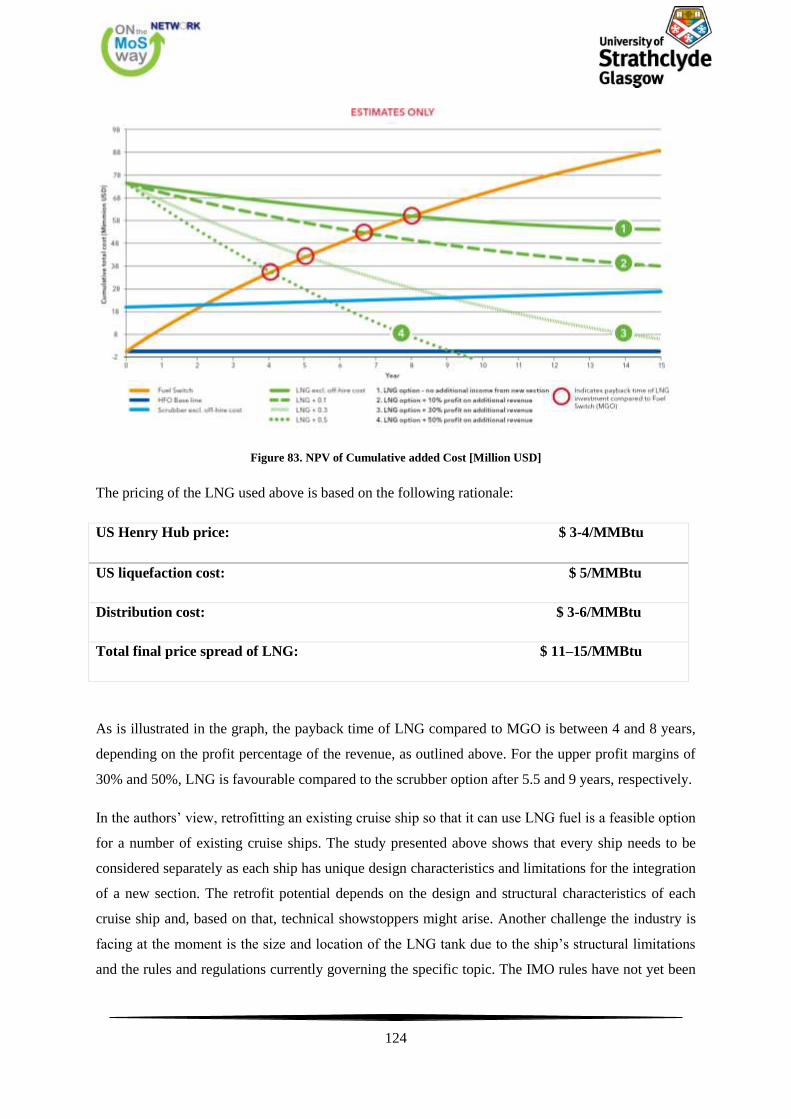
124
Figure 83. NPV of Cumulative added Cost [Million USD]
The pricing of the LNG used above is based on the following rationale:
US Henry Hub price: $ 3-4/MMBtu
US liquefaction cost: $ 5/MMBtu
Distribution cost: $ 3-6/MMBtu
Total final price spread of LNG: $ 11–15/MMBtu
As is illustrated in the graph, the payback time of LNG compared to MGO is between 4 and 8 years,
depending on the profit percentage of the revenue, as outlined above. For the upper profit margins of
30% and 50%, LNG is favourable compared to the scrubber option after 5.5 and 9 years, respectively.
In the authors’ view, retrofitting an existing cruise ship so that it can use LNG fuel is a feasible option
for a number of existing cruise ships. The study presented above shows that every ship needs to be
considered separately as each ship has unique design characteristics and limitations for the integration
of a new section. The retrofit potential depends on the design and structural characteristics of each
cruise ship and, based on that, technical showstoppers might arise. Another challenge the industry is
facing at the moment is the size and location of the LNG tank due to the ship’s structural limitations
and the rules and regulations currently governing the specific topic. The IMO rules have not yet been
125
confirmed. The strictest set of rules currently under discussion limits the maximum allowable tanks
size. The fuel that can be stored in the new mid-body section of a typical cruise ship is approximately
1,500 m3 which is equal to the energy of about 800 m3 of MGO.
This study has shown that retrofitting cruise ships to run on LNG – our crazy idea – is not only
technically but also financially feasible if an attractive LNG price can be achieved. The calculated
payback time is 4-8 years compared to MGO. LNG propulsion is a unique solution in that the ship
achieves compliance, saves money on fuel, and generates extra revenue from additional passenger
capacity. Certain ships now have a window of opportunity to take advantage of the potential financial
benefits of LNG propulsion. (DNV GL, 2014)

126
7. Standards and Guidelines for Natural Gas Fuelled Ship Projects
According to the Society of International Gas Carrier and Terminal Operators (SIGTTO) and the
Society for Gas as a Marine Fuel (SGMF) the LNG marine transportation industry has an enviable
safety record and, in the 49 years since the first commercial cargo was transported from Algeria to the
UK, 7,200 million m3 of LNG has been safely delivered on approaching 75,000 loaded voyages.
This excellent safety record stems from adherence to rigorous codes and standards for the design,
construction and operation of both the vessels employed and the marine terminals where they load and
discharge their cargo. The codes, standards and industry guidelines were written by drawing on the
expertise of the people engaged in the industry and they have been continuously updated and
reviewed in light of experience.
With the advent of ‘small scale’ LNG usage, particularly in its use as a marine bunker fuel, it is
essential that the knowledge and experience is publicised to new participants in the LNG industry.
This document provides a description of all guidance available and sufficient details to enable copies
to be found.
For ease of document navigation the guide is split into 4 sections; Project Development, Design,
Operations and Training
7.1. Project Development
1. NFPA 59A- Standard for the Production, Handling and Storage of Liquefied Natural Gas
(LNG) 2013 edition
This National Fire Protection Association standard applies to the location, design, construction,
maintenance and operation of all facilities that liquefy, store, vaporise and handle natural gas. It also
deals with the training of personnel involved with LNG.
http://www.nfpa.org
2. NFPA 52 - Vehicular Gaseous Fuel Systems Code
This National Fire Protection Association code applies to the design, installation, operation and
maintenance of LNG engine fuel systems on vehicles of all types, as well as to their associated fueling
(dispensing) facilities. It also applies to LNG to CNG facilities with LNG storage in ASME containers
of 70,000 gal (265 m3) or less.
http://www.nfpa.org
3. EN 1473:2007 Installation and Equipment for LNG - Design of Onshore Installations
This European Standard gives guidelines for the design, construction and operation of all onshore
liquefied natural gas installations, including those for the liquefaction, storage, vaporisation, transfer
127
and handling of LNG. Plants with a storage capacity of less than 200 tonnes are covered by EN
13645.
ISBN: 9 780 58050 229 3 3
4. Seveso III Directive EU Directive 2012/18/EU
The Seveso Directive deals with the control of onshore major accident hazards involving dangerous
substances. The current directive, Seveso III, entered into force in August 2012 and will become fully
applicable in June 2015.
http://ec.europa.eu/environment/seveso
5. USCG - Guidance Related to Waterfront LNG Facilities – Including Information on
Assessing the Suitability of Waterways for LNG Marine Traffic
This circular provides guidance to an applicant seeking a permit to build and operate a shore side
LNG terminal. It looks at the timing and scope of the process that is necessary to ensure full
consideration is given to the safety and security of the port, the facility and the vessels transporting
the LNG.
http://www.uscg.mil/hq/cg5/nvic/pdf/2011/NVIC%2001-2011%20Final.pdf
6. Guide to Contingency Planning for Marine Terminals Handling Liquefied Gases in Bulk –
SIGTTO
Covers the safe storage and transfer of liquefied gases at marine terminals.
ISBN: 9 781 85609 215 9
7. Guidance on performing risk assessment in the design of onshore LNG installations including
the ship/shore interface – ISO draft 116901
This Technical Specification provides a common approach and guidance to those undertaking
assessment of the major safety hazards as part of the planning, design and operation of LNG facilities
onshore and at shoreline, using risk based methods and standards, to enable a safe design and
operation of LNG facilities. The environmental risks associated with an LNG release are not
addressed.
The Specification aims to be applied both to export and import terminals, but can be applicable to
other facilities such as satellite and peak shaving plants.
128
It applies to all facilities inside the perimeter of the terminal, and all hazardous materials including
LNG and associated products.
www.ogp.org.uk/index.php/download_file/view/408/2876/
8. LNG Operations in Port Areas – SIGTTO
Provides guidance to best practice in managing gas shipping operations within ports. It also carries a
useful profile of the risks associated with gas operations.
ISBN: 9 781 85609 256 2
9. BS EN 13645:2002 - Installations and equipment for LNG – Design of onshore installations
with a storage capacity between 5 t and 200 t
This European Standard specifies requirements for the design and construction of onshore stationary
LNG installations with a total storage capacity of between 5 t and 200 t. This standard is not
applicable to liquefaction process facilities based on hydrocarbon refrigerants. Larger installations are
treated according to EN 1473:1997.
The installations to which this standard is applicable include:
• LNG satellite plants. The LNG may be supplied by road tankers, barge or rail carriers. After storage,
LNG is vaporized and sent out to consumers
• LNG gas fuelling stations for vehicles.
The installation is limited from the gas inlet or the loading LNG area to the gas outlet or the unloading
LNG area. Filling systems are not covered.
ISBN: 0 580 39202 3
10. 33 CFR Part 127 – Waterfront Facilities Handling LNG and LHG
This CFR includes guidance on general requirements for design and construction, equipment,
operations, maintenance, personnel training, fire fighting, and security. It covers any structure on, in,
or under the navigable waters of the United States, or any structure on land or any area on shore
immediately adjacent to such waters, used or capable of being used to transfer LNG, in bulk, to or
from a vessel. The regulations apply to large and small scale LNG projects, including tank truck
operations.
http://www.ecfr.gov
129
11. Port Marine Safety Code – UK DfT 2000
The Code includes a brief general summary of the main duties and powers that are common to many
harbour authorities in relation to marine operations. It also contains guidance as to how some of these
duties and powers should be exercised consistent with good practice.
There are several general principles:
• A harbour authority has statutory and non-statutory duties
• duties include an obligation to conserve and facilitate the safe use of the harbour; and a duty of care
against loss caused by the authority’s negligence
• duties to ensure the safety of marine operations are matched with general and specific powers to
enable the authority to discharge these duties.
The Code does not, for example, relate to duties and responsibilities deriving from health and safety
legislation, 2 and (with some exceptions) those relating to the safety of vessels under the Merchant
Shipping Acts.
http://www.dft.gov.uk/mca/pmsc_oct_2009.pdf
12. Guidance on Risk Analysis and Safety Implications of a Large LNG Spill Over Water –
Sandia National Laboratories, December 2004
This report reviews several existing studies of LNG spills with respect to their assumptions, inputs,
models, and experimental data. Based on this review and further analysis, the report provides
guidance on the appropriateness of models, assumptions, and risk management to address public
safety and property relative to a potential LNG spill over water. It presents a general scale of possible
hazards of spills occurring from LNG class carriers with a cargo capacity ranging of 125,000-150,000
m3.
http://www.dtic.mil/cgi-bin/GetTRDoc?AD=ADA442674
13. Breach and Safety Analysis of Spills Over Water from Large LNG Carriers – Sandia
National Laboratories, May 2008
Building on the research and analyses presented in A12, Sandia reassessed emerging accidental and
intentional threats and then conducted detailed breach analyses for the new large LNG carrier designs.
The report is based on the estimated breach sizes, breach locations, and LNG carrier configurations
from LNG class carriers with cargo capacities up to 265,000 m3.The report estimates LNG spill rates
and volumes, and analyzes thermal hazard and vapor dispersion distances. It looks at the expected
130
range of potential hazards from a large LNG carrier spill over water, and discusses the risk
management approaches to minimize.
http://www.energy.ca.gov/lng/documents/2008-09-11_SANDIA_2008_Report.PDF
14. Recommendations on the Prediction of Thermal Hazard Distances from Large LNG Pool
Fires on Water for Solid Flame Models – Sandia National Laboratories, December 2011
Provides recommendations on predicting thermal hazard distances resulting from large LNG pool
fires on water by looking at burn rate, flame height, surface emissive power (SEP), and transmissivity.
The recommendations are based upon knowledge gained from A12 and A13.
http://prod.sandia.gov/techlib/access-control.cgi/2011/119415.pdf
15. Fuel Storage Transportation and Supply Agreements - Witherby Seamanship
First published in 2004, this book analyses the legal and commercial issues associated with the
structuring arrangements for the storage, transportation and supply of processed fuels from the
perspective of the relationship between the sales company and the independent contractors who
provide services to it.
ISBN: 9 781 85609 250 0
16. LNG Overview - US Federal Energy Regulatory Commission
This overview, which is produced by the Federal Energy Regulatory Commission (FERC), provides
useful information to citizens regarding the nature of LNG and its transportation and storage.
www.ferc.gov/for-citizens/citizen-guides.asp
17. The Phoenix Large Scale LNG Pool Fire Experiments – Sandia 2010
This report presents test data and results of a series of five reduced scale (gas burner) tests to assess
flame height to fire diameter ratios as a function of non-dimensional heat release rates for
extrapolation to large scale LNG fires. Two fire tests of LNG spills of 21 and 81 m in diameter were
conducted in 2009 to improve the understanding of flame height, smoke production, and burn rate
and, therefore, the physics and hazards of large LNG spills and fires.
http://prod.sandia.gov/techlib/access-control.cgi/2010/108676.pdf
18. Site Selection and Design for LNG Ports and Jetties (IP no 14) – SIGTTO
131
A Guide to the minimum design criteria when a port is built or altered to accommodate LNG carriers.
ISBN: 1 85609 129 5
19. Calculation of Radiation Effects from LNG Fires – Dominic Nedelka - GdFSuez
This document describes a research programme on LNG fires that was conducted by Gaz de France,
in cooperation with industry partners, at Montoir in 1987.
http://onlinelibrary.wiley.com/doi/10.1002/9780470590232.refs/summary
7.2. Design
1. IMO draft IGF Code
The purpose of this Code is to provide an international standard for ships that are not covered by the
IGC Code, but that are operating with gas or low flashpoint liquids as fuel.
The Code provides mandatory criteria for the arrangement and installation of machinery, equipment
and systems to minimize the risk to the ship, its crew and the environment.
www.IMO.Org
2. IMO IGC Code
This Code provides an international standard for the safe carriage, by sea in bulk, of liquefied gases
and certain other substances. Through consideration of the products carried, it prescribes the design
and construction standards of the ships involved and the equipment they should carry to minimize risk
to the ship, its crew and to the environment.
ISBN: 9 789 28011 277 1
3. BS EN 1160 1997 - Properties and materials for LNG (Being revised as an ISO - CD 16903)
This International Standard gives guidance on the characteristics of liquefied natural gas (LNG) and
the cryogenic materials used in the LNG industry. It also gives guidance on health and safety matters.
It is intended to act as a reference document for the implementation of other standards in the liquefied
natural gas field. It is intended as a reference for use by persons who design or operate LNG facilities.
ISBN: 0 580 26446 7
4. ESD Arrangements and Linked Ship/Shore Systems for Liquefied Gas Carriers – SIGTTO

132
This SIGTTO guidance note was produced due to members’ concerns about the different
interpretations of the functional requirements for ESD systems, particularly differences between the
needs of the LNG industry and those of the LPG industry, and how these may interact with linked
ship/shore shutdown systems (2009).
ISBN: 9 781 90533 190 1
5. Protection Against Ignitions Arising Out of Static, Lightning, and Stray Currents - API
Recommended Practice 2003, 7th Edition
Presents the current state of knowledge and technology in the fields of static electricity, lightning, and
stray currents applicable to the prevention of hydrocarbon ignition in the petroleum industry and is
based on both scientific research and practical experience. The principles discussed are applicable to
other operations where ignitable liquids and gases are handled.
http://publications.api.org/
6. EN 1474-1:2008 - Installation and Equipment for LNG – Design and testing of marine
transfer systems – Part 1: Design and testing of transfer arms (Being revised as ISO/DIS 16904)
This European Standard specifies the design, minimum safety requirements and inspection and testing
procedures for LNG transfer arms intended for use on conventional onshore LNG terminals. It also
covers the minimum requirements for safe LNG transfer between ship and shore. Although the
requirements for remote control power systems are covered, the standard does not include all the
details for the design and fabrication of standard parts and fittings associated with transfer arms.
ISBN: 9 780 58057 033 2
7. EN 1474-2:2008 - Installation and Equipment for LNG – Design and testing of marine
transfer systems – Part 2: Design and testing of transfer hoses
This European Standard provides general guidelines for the design, material selection, qualification,
certification, and testing details for LNG transfer hoses for offshore transfer or on coastal weather-
exposed facilities for aerial, floating and submerged configurations or a combination of these. While
this European Standard is applicable to all LNG hoses, there may be further specific requirements for
floating and submerged hoses.
The transfer hoses will be designed to be part of transfer systems (fitted with ERS, QCDC, handling
systems, hydraulic and electric components etc.)
ISBN: 9 780 58057 977 6
8. Manifold Recommendations for Liquefied Gas Carriers (SIGTTO)
133
These recommendations were developed by SIGTTO, in conjunction with OCIMF, to bring together,
in one document, the manifold arrangements and strainer guidelines for LPG and LNG carriers. The
document’s aim is to promote improved safety and efficiency in operations and to assist in planning
the position of loading and discharging facilities in new jetties.
ISBN: 9 781 85609 494 8
9. Energy Institute Model Code of Safe Practice Part 15: Area Classification Code for
Installations Handling Flammable Fluids
(formerly referred to as IP 15) EI 15 provides methodologies for hazardous area classification around
equipment that stores or handles flammable fluids in the production, processing, distribution and retail
sectors. It is a sector specific approach to achieving the hazardous area classification requirements for
flammable fluids required in the UK by the Dangerous Substances and Explosive Atmospheres
Regulations (DSEAR) 2002.
ISBN: 9 780 85293 418 0
10. IEC 60092-502:1999 - Electrical Installations in Ships: Tankers - Special Features
This part of IEC 60092 deals with electrical installations in tankers carrying liquids that are
flammable, either inherently or due to their reaction with other substances, or flammable liquefied
gases.
ISBN: 0 580 39032 2
11. BS EN 13645:2002 - Installations and equipment for LNG – Design of onshore installations
with a storage capacity between 5 t and 200 t
This European Standard specifies requirements for the design and construction of onshore stationary
LNG installations with a total storage capacity of between 5 t and 200 t. This standard is not
applicable to liquefaction process facilities based on hydrocarbon refrigerants. Larger installations are
treated according to EN 1473:1997.
The installations to which this standard is applicable include:
• LNG satellite plants. The LNG may be supplied by road tankers, barge or rail carriers. After storage,
LNG is vaporized and sent out to consumers
• LNG gas fuelling stations for vehicles.
The installation is limited from the gas inlet or the loading LNG area to the gas outlet or the unloading
LNG area. Filling systems are not covered.
ISBN: 0 580 39202 3
134
12. Mooring Equipment Guidelines – OCIMF
These guidelines provide an extensive overview of the requirements for safe mooring, from both a
ship and terminal perspective, including calculation of a ship's restraint requirements, the selection of
rope and fitting types and the retirement criteria for mooring lines.
ISBN: 9 781 90533 132 1
13. BS 4089:1999 Specification for Metallic Hose Assemblies for Liquid Petroleum Gases and
Liquefied Natural Gases
This British Standard specifies requirements and test methods for metallic hose assemblies used for
the loading and unloading of liquefied petroleum gases under pressure.
NOTE: These hoses are primarily used for road and rail tankers or for ship to shore duties.
ISBN: 0 580 33058 3 9
14. NFPA 59A - Standard for the Production, Handling and Storage of Liquefied Natural Gas
(LNG) 2013 edition
This National Fire Protection Association standard applies to the location, design, construction,
maintenance and operation of all facilities that liquefy, store, vaporise and handle natural gas. It also
deals with the training of personnel involved with LNG.
http://www.nfpa.org
15. EN 1473:2007 Installation and Equipment for LNG - Design of Onshore Installations
This European Standard gives guidelines for the design, construction and operation of all onshore
liquefied natural gas installations, including those for the liquefaction, storage, vaporisation, transfer
and handling of LNG. Plants with a storage capacity of less than 200 tonnes are covered by EN
13645.
ISBN: 9 780 58050 229 3
16. LNG Operations in Port Areas – SIGTTO
Provides guidance to best practice in managing gas shipping operations within ports. It also carries a
useful profile of the risks associated with gas operations.
ISBN: 9 781 85609 256 2
135
17. Guidance on performing risk assessment in the design of onshore LNG installations
including the ship/shore interface – ISO draft 116901
This Technical Specification provides a common approach and guidance to those undertaking
assessment of the major safety hazards as part of the planning, design and operation of LNG facilities
onshore and at shoreline, using risk based methods and standards, to enable a safe design and
operation of LNG facilities. The environmental risks associated with an LNG release are not
addressed.
The Specification aims to be applied both to export and import terminals, but can be applicable to
other facilities such as satellite and peak shaving plants. It applies to all facilities inside the perimeter
of the terminal, and all hazardous materials including LNG and associated products.
www.ogp.org.uk/index.php/download_file/view/408/2876/
18. Liquefied Gas Fire Hazard Management – SIGTTO
Discusses the principles of liquefied gas fire prevention and firefighting.
ISBN: 9 781 85609 265 4
19. American Bureau of Shipping Publication 181: ABS Guide for Propulsion and Auxiliary
Systems for Gas Fueled Ships
Provides guidance for the design, construction and survey of vessels utilizing gas as a fuel and is
focused on systems and arrangements for propulsion and auxiliary systems. The Guide is for
application to ship types not falling under the scope of the IGC Code. 10
http://www.eagle.org/eagleExternalPortalWEB/ShowProperty/BEA%20Repository/Rules&Guides/Cu
rrent/181-GasFueledShips/Guide
20. A Risk Based Approach for the Provision of Firefighting Equipment on Liquefied Gas
Jetties – SIGTTO
The book describes a systematic risk management approach and applies it to two hypothetical but
realistic installations, a town jetty and a remote jetty.
ISBN: 9 781 85609 184 8
21. Bureau Veritas – ‘Safety Rules for Gas-Fuelled Engine Installations in Ships’ NR 529 (last
edition May 2011)
136
Applies to ships fitted with internal combustion engine installations using natural gas as fuel. The
engines may use either a single fuel (gas) or dual fuel (gas and fuel oil), and the gas may be stored in
gaseous (CNG) or liquid (LNG) state.
http://www.veristar.com/content/static/veristarinfo/images/4707.9.529NR_2011-05.pdf
22. EU ATEX Directives
ATEX is the name commonly given to the two European Directives for controlling explosive
atmospheres:
1) Directive 99/92/EC (also known as ‘ATEX 137’ or the ‘ATEX Workplace Directive’) is on
minimum requirements for improving the health and safety protection of workers potentially at risk
from explosive atmospheres.
2) Directive 94/9/EC (also known as ‘ATEX 95’ or ‘the ATEX Equipment Directive’) is on the
approximation of the laws of Members States concerning equipment and protective systems intended
for use in potentially explosive atmospheres.
http://ec.europa.eu/enterprise/sectors/mechanical/atex/
http://ec.europa.eu/enterprise/sectors/mechanical/documents/legislation/atex/
23. IMO IMDG Code
The International Maritime Dangerous Goods (IMDG) Code lays down basic principles; detailed
recommendations for individual substances, materials and articles, and a number of recommendations
for good operational practice including advice on terminology, packing, labelling, stowage,
segregation and handling, and emergency response.
ISBN: 9 789 28011 513 0
24. Part 6 Chapter 13, Gas Fuelled Ship Installations, Jan 2012 – Det Norske Veritas
This rule chapter includes requirements from the ship’s gas fuel bunkering connection up to and
including the gas consumers. Has requirements for arrangement and location of gas fuel tanks and all
spaces with gas piping and installations, including requirements to entrances to such spaces.
Hazardous areas and spaces due to the gas fuel installations are defined. Requirements for control,
monitoring and safety systems for the gas installations are included, plus additional monitoring
requirements for gas engines and compressors.
http://exchange.dnv.com/publishing/ruleshslc/2012-04/ts613.pdf
137
25. ‘Rules and Regulations for the Classification of Natural Gas Fuelled Ships’ - July 2012 –
Lloyd’s Register
These Rules specify requirements for gas fuelled systems in ships other than LNG Carriers and cover
both single fuelled (gas only) and dual fuelled (gas and oil fuel) machinery, with gas fuel stored and
supplied at 10 bar or less.
http://www.webstore.lr.org/products/419-rules-and-regulations-for-the-classification-of-natural-gas-
fuelled-ships-july-2012.aspx
26. LNG Fire Protection and Emergency Response, 2007 Edition IChem E
This booklet was written to improve understanding of the nature and hazards of LNG and the special
fire hazards management and emergency response measures required for such facilities.
ISBN: 9 780 85295 515 4
27. Accident Prevention - The Use of Hoses and Hard-Arms at Marine Terminals Handling
Liquefied Gas - 2nd Ed – SIGTTO
This paper covers accidents relating to hoses, hard-arms and pipeline incidents close to ship or shore
manifolds. The report only covers the liquefied gas industry. Where possible, and resulting from
incidents, the design and operation of various equipment types is discussed.
ISBN: 9 781 85609 114 5
28. The Selection and Testing of Valves for LNG Applications – SIGTTO
This document provides guidance to designers and operators on the general requirements for valves
for LNG service, which are generally designed with an operating temperature range of +80°C to –
196°C.This guidance is primarily intended for the shipping and storage of these products but may be
applied throughout the LNG and LPG industries as appropriate.
ISBN: 9 781 85609 580 8
29. BS EN 1474 Part 3 2008 - Installation and Equipment for LNG Design and testing of marine
Transfer Systems - Offshore transfer systems
This European Standard gives general guidelines for the design of LNG transfer systems intended for
use on offshore transfer facilities or on coastal weather exposed transfer facilities. The transfer
138
facilities considered may be between floating units, or between floating and fixed units. The specific
component details of the LNG transfer systems are not covered by this European Standard.
ISBN: 9 780 58057 978 3
30. BS EN 60079-0 2009 Explosive Atmospheres
This part of IEC 60079 specifies the general requirements for construction, testing and marking of
electrical equipment and Ex-components intended for use in explosive atmospheres. Unless modified
by one of the standards supplementing this standard, electrical equipment complying with this
standard is intended for use in hazardous areas in which explosive atmospheres exist under normal
atmospheric conditions of:
• temperature –20°C to +60°C;pressure 80 kPa (0,8 bar) to 110 kPa (1,1 bar); and
• air with normal oxygen content, typically 21 % v/v.
ISBN: 9 780 58055 443 8
31. BS EN 60079-Part 29-2 2007 Explosive Atmospheres Gas detectors – Selection installation,
use and maintenance of detectors for flammable gases and oxygen
This part of IEC 60079-29 gives guidance on, and recommended practice for, the selection,
installation, safe use and maintenance of electrically operated group II apparatus intended for use in
industrial and commercial safety applications for the detection and measurement of flammable gases,
complying with the requirements of IEC 60079-29-1.
This standard applies to apparatus, instruments and systems that indicate the presence of a flammable
or potentially explosive mixture of gas or vapour with air by using an electrical signal from a gas
sensor to produce a meter reading, to activate a visual or audible pre-set alarm or by other device, or
by any combination of these.
ISBN: 9 780 58054 363 0
32. BS EN 12567: 2000 Industrial valves- Isolating valves for LNG – Specification for suitability
and appropriate verification tests
This European Standard specifies the general performance requirements of isolating valves (gate
valves, globe valves, plug and ball valves and butterfly valves) used in the production, storage,
transmission (by pipeline, rail, road or sea) of LNG.
ISBN: 0 580 36423 2
139
33. The IMO publication “Interim Guidelines on Safety for Natural Gas Fuelled Engine
Installations in Ships” IMO Resolution MSC 285 (86)
The Interim Guidelines were developed to provide an international standard for ships, other than
vessels covered by the IGC Code, with natural gas fuelled engine installations.
The goal of the Interim Guidelines is the provision of criteria for the arrangement and installation of
machinery for propulsion and auxiliary purposes, using natural gas as fuel. This is to create an
equivalent level of integrity in terms of safety, reliability and dependability as that which can be
achieved with new, and comparable, conventional oil-fuelled main and auxiliary machinery.
7.3. Operations
1. ISO 28460:2010 – Installation and equipment for LNG Ship-to-shore interface and port
operations
Specifies the requirements for ship, terminal and port service providers to ensure the safe transit of an
LNG carrier (LNGC) through the port area and the safe and efficient transfer of its cargo. It is
applicable to:
• Pilotage and vessel traffic services (VTS)
• Tug and mooring boat operators
• Terminal operators
• Ship operators
• Suppliers of bunkers, lubricants and stores and other providers of services while the LNGC is
moored alongside the terminal.
This International Standard applies only to conventional onshore LNG terminals and to the handling
of LNGCs in international trade.
ISBN: 9 780 58065 735 1
2. OGP Draft 118683 Guidelines for systems and installations for supply of LNG as fuel to ships
This draft technical specification provides guidance on the minimum requirements for the design and
operation of an LNG bunkering facility, including the interface between the LNG supply facilities and
receiving ship of both seagoing and inland trading vessel. It provides requirements and
recommendations for operator and crew competency, training, and the functional requirements for
equipment necessary to ensure safe LNG bunkering operations of LNG fuelled ships.
http://www.ogp.org.uk/index.php/download_file/view/473/2876/
140
3. LNG STS Transfer Guidelines – SIGTTO
Guidelines for the side by side STS transfer operations of LNG between commercially trading LNG
carriers at anchor, alongside a shore jetty or while underway.
The guidance applies to seagoing ships and may also be useful for reference when establishing rules
and procedures for transfer operations between seagoing ships and LNG Regasification Vessels
(LNGRV) or LNG Floating Storage and Offloading Vessels in inshore waters.
These guidelines may also be used to develop procedures to facilitate emergency STS transfer
operations.
ISBN: 9 781 85609 439 9
4. ESD Arrangements and Linked Ship/Shore Systems for Liquefied Gas Carriers – SIGTTO
This SIGTTO guidance note was produced due to members’ concerns about the different
interpretations of the functional requirements for ESD systems, particularly those differences between
the needs of the LNG industry and those of the LPG industry and how these may interact with linked
ship/shore shutdown systems (2009).
ISBN: 9 781 90533 190 1
5. IMO Revised Recommendations on the Safe Transport of Dangerous Cargoes and Related
Activities in Port Areas
These Recommendations set out a framework within which legal requirements can be prepared by
Governments, whether for the first time or as a revision, to ensure the safe transport and handling of
dangerous cargoes in port areas. There commendations do not specify standards of construction and
equipment.
ISBN: 9 789 28011 472 0
6. BS EN 1474-3:2008 - Installation and Equipment for LNG. Design and testing of marine
transfer systems - Offshore transfer systems
This European Standard gives general guidelines for the design of LNG transfer systems intended for
use on offshore transfer facilities or on coastal weather exposed transfer facilities. The transfer
facilities considered may be between floating units, or between floating and fixed units. The specific
component details of the LNG transfer systems are not covered by this European Standard.
ISBN: 9 780 58057 978 3

141
7. International Safety Guide for Oil Tankers and Terminals (ISGOTT) – OCIMF/IAPH/ICS
Provides operational advice for personnel involved in tanker and terminal operations. It is NOT a
definitive description of how tanker and terminal operations are conducted.
It is a general industry recommendation that a copy of ISGOTT is kept and used onboard every tanker
and in every terminal so that there is a consistent approach to operational procedures and shared
responsibilities for operations at the ship/shore interface.
ISBN: 9 781 85609 291 3
8. Mooring Equipment Guidelines – OCIMF
These guidelines represent best known mooring technology and practice.
The guidelines address conventional and alternative mooring systems but are not intended to apply to
vessels operating in extreme environments.
ISBN: 9 781 90533 132 1
9. BS 4089:1999 - Specification for Metallic Hose Assemblies for Liquid Petroleum Gases and
Liquefied Natural Gases
This British Standard specifies requirements and test methods for metallic hose assemblies used for
the loading and unloading of liquefied petroleum gases under pressure.
NOTE: These hoses are primarily used for road and rail tankers or for ship to shore duties.
ISBN: 0 580 33058 3
10. ISPS Code – IMO
The International Ship and Port Facility Security (ISPS) Code is a comprehensive set of measures. It
has two parts, one mandatory and one recommendatory.
The Code provides a standardised, consistent framework for evaluating risk, enabling Governments to
offset changes in threat with changes in vulnerability for ships and port facilities through
determination of appropriate security levels and corresponding security measures.
ISBN: 9 789 28011 544 4
11. LNG Operations in Port Areas – SIGTTO
142
Provide guidance to best practice in managing gas shipping operations within ports. It also carries a
useful profile of the risks associated with gas operations.
ISBN: 9 781 85609 256 2
12. Contingency Planning and Crew Response Guide for Gas Carrier Damage at Sea and in
Port Approaches – SIGTTO
Addresses the aspects of contingency planning that are relevant to the liquefied gas carrier and
provides recommended crew responses to emergency situations that cause ship damage. While not an
exhaustive guide to all conditions, it will be found to be applicable to the majority of accident
situations.
ISBN: 9 781 85609 172 5
13. Liquefied Petroleum Gas Sampling Procedures – SIGTTO
A set of updated recommendations
ISBN: 9 781 90533 199 4
14. Guide to Contingency Planning for the Gas Carrier Alongside and Within Port Limits –
SIGTTO
Assists liquefied gas carriers and terminals in developing/reviewing their planning to minimise the
consequences of accidents and incidents
ISBN: 9 781 85609 173 2
15. The Safe Transfer of Liquefied Gas in an Offshore Environment (STOLGOE) – OCIMF
This publication primarily addresses the inter-relation between the F(P)SO and conventional gas
tankers operating in an SBS mooring configuration. It includes recommendations for mooring
equipment, considers mooring loads and operations, motions of the F(P)SO and gas tanker, station
keeping, cargo transfer equipment and cargo transfer operations.
Offshore operations involving the transfer of Liquefied Natural Gas (LNG) are not specifically
addressed in this document, but will be included in a future update once industry experience is
available on which to base guidance.
ISBN: 9 781 85609 400 9
143
16. Application of Amendments to Gas Carrier Codes Concerning Type C Tank Loading Limits
– SIGTTO/IACS
The object of this booklet is to remind ship owners and terminal operators of the improvements in
safety that the amendments provide.
ISBN: 9 781 85609 125 1
17. GIIGNL - LNG Custody Transfer Handbook
Serves as a reference manual on the procedures and equipment available to and used by the members
of GIIGNL to determine the energy quantity of LNG transferred between LNG ships and LNG
terminals. It is neither a standard nor a specification.
http://www.giignl.org/fileadmin/user_upload/pdf/Technical_study_group/Reports/GIIGNL-
LNG_CUSTODY_TRANSFER_HANDBOOK_-_final_3.01_03-2011.pdf
18. LNG Transfer Arms and Manifold Draining, Purging and Disconnection Procedure –
SIGTTO
This advice has been prepared following reports, from a number of members, that there is confusion
and misunderstanding among some ship and jetty operators over the safe conduct of this operation.
This advice specifically pertains to terminals employing rigid transfer arms. (The basic principles are
applicable for hose systems that may be used for LNG ship-to-ship transfer, but there will be
differences in the detail.)
http://www.sigtto.org/mf.ashx?ID=62769f00-e59d-437c-a7fb-713a5c135bd9.
19. Legal Issues in Bunkering - Trevor Harrison
An introduction to the law relating to the sale and use of marine fuels that offers a wealth of
information on key legal aspects of bunkering, including contracts, defaults, ship arrest and dispute
resolution. It also contains a section dealing with international conventions and national legislation on
environmental issues relevant to bunkering.
ISBN: 9 780 95480 976 8
20. Guidance for the Prevention of Rollover in LNG Ships – SIGTTO
For receiving terminals, the issues are generally well understood and suitable mitigation methods are
in place. For LNG ships, while the circumstances leading to rollover are quite unusual, rollover has
occurred, leading to the release of this information paper.
144
ISBN: 9 781 85609 558 7
21. ISO 6976: 1995 Natural Gas – Calculation of calorific values, density, relative density and
Wobbe index from composition
This standard specifies methods for the calculation of the superior and inferior calorific value, density,
relative density and Wobbe index of dry natural gas and other combustible gaseous fuels.
http://www.iso.org/iso/catalogue_detail.htm?csnumber=13531
22. LNG Bunkering Safety Checklists – IAPH
Three documents are currently in draft form for:
• Truck to ship
• ship to ship
• shore to ship LNG bunkering.
The final documents should be available in November 2013. These checklists will be made available
on the WPCI LNG Fuelled Vessels website and can be requested by sending an email to
23. ISO 10976 Refrigerated Light Hydrocarbon Fluids – Measurement of cargoes on board
LNG carriers
This International Standard establishes the steps to properly measure and account for the quantities of
cargoes on LNG carriers including, but not limited to, the measurement of liquid volume, vapour
volume, temperature and pressure and accounting for the total quantity of the cargo on board.
It describes the use of common measurement systems used on board LNG carriers, the aim of which
is to improve the general knowledge and processes in the measurement of LNG for all parties
concerned. It also provides general requirements for those involved in the LNG trade on ships and
onshore.
7.4. Training
1. STCW Convention – IMO
The Convention prescribes minimum standards relating to training, certification and watchkeeping for
seafarers which countries are obliged to meet or exceed.
ISBN: 9 789 28011 528 4
2. Liquefied Gas Handling Principles on Ships and in Terminals – SIGTTO
145
This book is for serving officers and terminal operational staff responsible for cargo handling
operations and personnel about to be placed in positions covering these duties.
ISBN: 9 781 85609 164 0
3. LNG Shipping Suggested Competency Standards – SIGTTO
This document has been prepared for the guidance of ship owners and operators who may be entering
LNG ship operation for the first time.
It highlights the statutory requirements for training LNG tanker crews and the provisions of STCW, as
it applies to gas tankers.
It also provides advice on the application of the ISM Code to the training and management of tanker
crews.
ISBN: 9 781 90533 136 9
4. LNG Shipping Knowledge -Witherby Seamanship
This book provides the underpinning knowledge to the SIGTTO LNG Shipping Competency
Standards, by summarising the tasks and knowledge considered necessary to perform in the industry,
broken down by rank.
ISBN: 9 781 85609 504 4
5. Liquefied Gas Carriers – Your Personal Safety Guide – SIGTTO
This book contains important advice for the personal safety of those serving on board liquefied gas
carriers. It explains the hazards associated with the variety of products that may be encountered and
addresses the steps needed to provide personal protection and that of the environment.
ISBN: 9 781 85609 572 3
6. Tanker Safety Training – Liquefied Gas - Witherby Seamanship
This book covers the IMO specialised level course (Model 1.06) for ships' officers serving on both
LNG and LPG carriers
ISBN: 9 781 85609 3415
7. Competence Related to the On Board Use of LNG as Fuel – DNV
146
The standard identifies a suggested minimum level of knowledge and skills for people in various roles
on board a vessel using LNG as fuel. This standard can be used in the following ways:
• As a reference to familiarise or assess people in their specific role in relation to LNG
• as a reference for global competence and defining training requirements
• as a guide to training providers, who are to develop courses according to the requirements of the
standard and needs of the industry
• as a reference document for e.g. certification of personnel.
http://exchange.dnv.com/publishing/stdcert/2013-04/standard3-325.pdf
8. IMO Specialized Training for Liquefied Gas Tankers: Model Course 1.06 1999 Edition
(TA106E)
ISBN: 9 789 28016 109 0
Availability
• All SIGTTO and OCIMF publications are available through Witherby Seamanship
• All ISO, BS and BS. EN standards are available through National Standards Bodies, although
drafts(CD and DIS) are not generally in the public domain
• IMO publications are available on their websitehttp://www.imo.org/
• NFPA publications are available on their website http://www.nfpa.org/
• ABS publications can be downloaded free of charge from
http://www.eagle.org/eagleExternalPortalWEB/?_nfpb=true&_pageLabel=abs_eagle_portal_marine_r
ules_guides_book
• GIIGNL publications are found on their website www.GIIGNL.org
147
References
Bibliography
ABS (2011) LNG Powered Vessels and the ABS Guide for the propulsion and auxiliary Systems for
ZGas fueled Ships
Algel, J., Bakosch, A. and Forsman, B. (2012) Feasibility Study on LNG Fuelled Short Sea and
Coastal Shipping in the Wider Caribbean Region. SSPA SWEDEN AB
Ashworth J., (2012). The Genesis of LNG Bunkers, LNG Markets Perspective. TRI-ZEN International
BP Group (2012) Statistical Review of World Energy.
BP Group (2015) Statistical Review of World Energy
Buhaug, Ø., Corbett J.J, Endresen, O., Eyring, V., Faber J., Hanayama, S., Lee, D., Lindstad, H.,
Mjelde, A., Palsson, C., Wanquing, W., Winebrake, J.J., Yoshida, K. (2009) Second IMO Greenhouse
Gas Study. International Maritime Organization, London.
California Energy Commission (2008) Available: http://www.energy.ca.gov/ [15 Jan 2015].
CNSS (2011). LNG supply chain definition, WP4 Activity 2, Action D
Congressional Research Service (2013) Europe’s Energy Security: Options and Challenges to Natural
Gas Supply Diversification
Consuegra, S. C. & Paalvast, M.S. M. (2010). Sustainability in Inland Shipping-The use of LNG as
Marine Fuel. Delft University of Technology, Delft.
CV Neptun 1200 (2014) Available: http://www.neptun-
germany.com/fileadmin/pdfs/cv_neptun_1200.pdf [15 Jan 2015].
Det Norske Veritas (2012) Shipping 2020. DNV
Einang, P.M. (2013). Gas fuelled ships Norwegian experience. MARINTEK.
European Commission (2012) LNG in Baltic Sea Ports. TEN-T Multi-Annual Programme: 2011-EU-
21005-S, Part of Priority Project 21
European Commission (2012) LNG infrastructure of filling stations and deployment in ships. TEN-T
Multi-Annual Programme: 2010-EU-21112-S, Part of Priority Project 21
European Commission (2013) Actions towards a comprehensive EU framework on LNG for shipping.
SWD (2013) 4 final. Brussels.
148
European Commission (2013) Quarterly Report Energy on European Gas Markets: Market
Observatory for Energy. DG Energy Volume 5, issue 4.
Gerd-Michael Wursig (2014) LNG as ship fuel. DNV GL
Gerd-Michael Wursig. (2013) LNG for ships-some key elements. DNV
Groenendijk W., (2013) LNG in transport: The views of the European LNG terminal operators. Gas
LNG Europe, Hamburg
Gumpel, S. (2012). LNG Fuel Systems: Certification & Approval. ABS.
Harperscheidt, J. (2011). Bunkering, infrastructure, storage, and processing of LNG
Joslin, O. (2015) Small scale LNG Bunkering, safety, standardisation and its regulations
Levander O. & Sipilä T., (2008) LNG auxiliary power in port for container vessels. In Detail
Lloyd’s Register (2012a) LNG-fuelled deep sea shipping: The outlook for LNG bunker and LNG-
fuelled newbuild demand up to 2025.
Lloyd’s Register (2012b) Understanding exhaust gas treatment systems: Guidance for shipowners
and operators.
Lowell, D. (2013) Assessment of the fuel cycle impact of Liquefied Natural Gas as used in
international shipping. The International Council On Clean Transportation.
Maffii F., Molocchi A., Chiffi C. (2007) External Costs of Maritime Transport. European Parliament,
Policy Department B: Structural and Cohesion Policies: Transport and Tourism, Brussels.
MAN Diesel & Turbo (2012) Propulsion Trends in Container Vessels. Copenhagen
Maritime Gas Fuel Logistics (2008) Developing LNG as a clean fuel for ships in the Baltic and North
Seas.
Meyer Werft (2013). Building an LNG driven vessel
Miller,J. and Façanha,C. (2014) THE STATE OF CLEAN TRANSPORT
POLICY. Available:http://www.theicct.org/sites/default/files/publications/ICCT_StateOfCleanTransp
ortPolicy_2014.pdf. [15th Jan 2015].
Nielsen, C. & Schack,C. (2012). VESSEL EMISSION STUDY: COMPARISON OF VARIOUS
ABATEMENT TECHNOLOGIES TO MEET EMISSION LEVELS FOR ECA’s. GREEN SHIP OF
THE FUTURE.
Nilsson L., Bengtsson N., Pålsson C., (2011) Ships Visiting European Ports. IHS Fairplay,
Gothenburg.
Plan Bleu (2010) Maritime Transport of Goods in the Mediterranean. Blue Plan Papers 7.
Rakkola, A. (2015). LNG Machinery. Meyer Turku
149
Ratner M., Belkin P., Nickol J., Woehrel S., (2013) Europe’s Energy Security: Options and
Challenges to Natural Gas Supply Diversification. Congressional Research Service
SAFEMED, (2008) Study of Maritime Traffic Flows in the Mediterranean Sea. EU-Funded MEDA
Regional Project: Euromed Cooperation on Maritime Safety and Prevention of Pollution from Ships -
SAFEMED (MED 2005/109-573).
Schinas Ο. & Bani J., (2012) The impact of a possible extension at EU level of SECA’s to the entire
European coastline. European Parliament, Policy Department B: Structural and Cohesion Policies,
Transport and Tourism, Brussels.
SDARI (2012) LNG Bunker Vessel 6500 cbm
SIGTTO, (2014). Standards and Guidelines for Natural Gas Fuelled Ship Projects
Standaert, K. (2015) Developing LNG infrastructure in Europe. GLE
Swedish Marine Technology Forum (2010) LNG bunkering Ship to Ship procedure.
Swedish Marine Technology Forum (2011) LNG supply chain definition. CNSS WP4 Activity 2,
Action D.
The Danish Maritime Authority (2011) Baseline Report, North European LNG Infrastructure Project-
A feasibility study for an LNG filling station infrastructure. DMA, Copenhagen.
The Danish Maritime Authority (2012a) Appendices, North European LNG Infrastructure Project-A
feasibility study for an LNG filling station infrastructure. DMA, Copenhagen.
The Danish Maritime Authority (2012b) Full Report, North European LNG Infrastructure Project-A
feasibility study for an LNG filling station infrastructure. DMA Copenhagen.
Tzannatos E. (2010) Ship emissions and their externalities for the port of Piraeus - Greece.
Atmospheric Environment, doi:10.1016/j.atmosenv.2010.03.018.
UK Ports Directory (2014) Available: http://www.uk-ports.org/grangemouth [15 Jan 2015].
Unseki, T. (2013) Environmentally Superior LNG-Fueled Vessels. Mitsubishi Heavy Industries
Technical Review Vol. 50 No. 2. Wärtsilä (2009) WÄRTSILÄ Engines WÄRTSILÄ 20
Wärtsilä (2012a) WÄRTSILÄ 34DF Product Guide.
Wärtsilä (2012b) WÄRTSILÄ 50DF Product Guide.
Wartsila, (2013) Shipping in the gas age.
Wikander, M.(2015) LNG Fuel for Shipping. FKAB Marine Design
Zoglia, P. (2013) Gas Storage and supply systems. Wartsila
150
Web Sites
http://blogs.dnvgl.com/lng/2013/06/finally-a-new-lng-tank-on-the-market/
http://www.marinediesels.info/2_stroke_engine_parts/Other_info/dual_fuel.htm
www.cruisemarketwatch.com
http://www.marinediesels.info
http://www.marinediesels.info/
http://blogs.dnvgl.com/
http://www.elbehafen.de/node/388
http://www.nordicmarket.de/news/6038/brunsbuettel_ports_deutsche_maritime_branche_ruestet_sich
_fuer_lng.htm
http://www.hafen-hamburg.de/
http://siriusshipping.eu/our-fleet/seagas/
http://www.whitesmoke.se/en/the-ws3-design-evolves-2013-01-08