general descriptive information - etleretler.com/docs/bsp/972/972-100-100_i1.pdf · ing manual twx...
TRANSCRIPT

J
f
I (/
'(
(
I
J
BELL SYSTEM PRACTICES Plant Series
SECTION 972-100-100 Issue 1, August, 1961
AT&TCo Standard
DIAL TELETYPEWRITER EXCHANGE SYSTEM
GENERAL DESCRIPTIVE INFORMATION
CONTENTS
1. INTRODUCTION • . .
2. GENERAL PLAN OF THE DIAL TWX SYSTEM
A. General
B. Station Equipment Changes from the Standpoint of the Customer • • • •
C. Station ·Equipment Changes to Adapt Teletypewriter Machines to the Telephone Network
D. Central Office Switching and Message Accounting Arrangements
E. Assistance Switc,!Jboards for TWX Traffic • . , • . • • •
F. Other Positions for TWX Traffic . .
G. Changes in Interoffice Trunk Facilities .
Echo Suppressor Disabler . SF Signaling Modification •
H. New or Modified Subscriber Line
Facilities . • • •
Divided Access Line Circuit . Loop Extensio~n Facilities . MF Signaling Circuit for Line Concentrator No. 1 A •
I. Maintenance and Testing Arrangements . . .
3. DESCRIPTION OF NEW OR MODIFIED EQUIPMENT FOR DIAL TWX SERVICE •
A. General
B. Station Equipment
Teletypewriter e._quipment Subscriber Set
Data Set lOlA .
PAGE
2
2
2
3
3
3
5
5
5
6
6
7
7
7
7
8
8
CONTENTS
C. Subscriber Line Facilities . General . • • • Divided Access Line Circuit • Loop Extension Facilities . Line Concentrator No. 1 A and Concentrator MF Signaling Circuit •
D. Interoffice Trunk Facilities
Echo Suppressor Disabler Elimination of 2000-Cycle SF Signaling • • • • •
E. Assistance Switchboards •
General . • • . • • TWX Switchboard Positions .
. TWX Switchboard Circuits Auxiliary Switchboard Facilities •
F. Other Dial TWX Switchboard Units •
Information Desk Service Observing Desk • •
G. Maintenance and Testing Equipment •
Automatic Test Line • • • Portable Station Test Meter • Telegraph Test Center.
4. METHOD OF OPERATION •
A. General
B. Customer-Dialed Calls to Another TWX Stcition • •
Attended Stations - Keyboard Sending • • • • . • Unattended Terminating Station Tape Sending Station • • •
C. Local and Test Operation of TWX Stations . • •
D. TWX Calls via the Assistance Switchboard • . • •
E. Variations on Calls via the Assistance Switchboard
@American Telephone and Telegraph Company, 1961 Printed in U.S.A.
PAGE'
10 10 10 10
12
13 13
13
13 13 14 14 15
16
16 16
17
17 17 17
17
17
18
18
19 19
19
20
21
Page 1

SECTION 972-100-100
Figures PAGE
-Manual TWX Operation • • . • 23
2 - General Concept Gf Manuoi--JW)E--Trunking Plan • - . --.- -:----;------:-- • 23
3 - General Plan of the Dial TWX System . 24
4 - Basic Maintenance Arrangements for Dial TWX Stations . . . . . 25
5 -Data Set lOlA and Subscriber Set 689A Mounted on 28 KSR Teletypewriter . • • • • .
SA- Data Set lOlA and Subscriber Set 691 A3 Associated With 15-Type Teletypewriter • . . • • .
6 - Data Set 101 A, Principle of Operation
7 - Representative Arrangements of Subscriber Line Facilities . . •
8 - Switchboard Connection into the Network • • • • • • • • •
9 - Physical Layout of 6A Switchboard •
10 - Block Diagram of Switchboard Circuits . . . • • •
11 - Plan View of the Switchboard Keyshelf .
12 - Sample Copy Obtained from Use of the Automatic Test Line • •
13 - Flow Diagram of a TWX Connection Between AHended Stations • • • •
1. INTRODUCTION
26
26
27
28
29
29
30
30
31
32
1.01 This section describes in general terms the dial teletypewriter exchange (TWX) sys
tem. This system has been developed to improve the manual TWX system which was introduced' as a new service in 1931.
1.02 Manual TWX service makes use of manu-ally operated switchboards, equipped with
14-type (tape-printing) teletypewriters and interconnected by a separate network of telegraphgrade trunks. In recent years the number of manual switchboard locations has increased to about 115. None of these switchboards has trunks to all of the others, and most of them have trunks to less than ten others; thus,- a good deal of multilink switching has been required. TWX stations
Page 2
are served by de loops and, where appropriate, de TWX line concentrators are used. Switching is performed and supervisory signals are given by teletypewriter (TTY) cl,laracters received at and sent from the TTY at the operator position.
1.03 Fig. 1, attached, is a simple diagram show-ing how manual TWX connections are
established using the manual TWX switchboards. Fig. 2 indicates the general concept of the existing manual TWX trunking plan.
1.04 The conversion of TWX service to dial operation will be accomplished by making
use of the existing telephone switching and transmission network. This obviates the need for developing and installing an entirely new system of automatic switching centers and permits the use of the extensive and efficient telephone interoffice network, with only a relatively small increase in facilities to accommodate the added TWX traffic.
1.05 Since TWX service, now and in the future after dial conversion, is limited to com
munication by TTY code, certain additions and modifications are required in TWX station equipment and in portions of the telephone plant which will be used. The description of the dial TWX system contained in this section is limited to the new or modified equipment required.
2. GENERAL PLAN OF THE DIAL TWX SYSTEM
A. General
2.01 Conversion of TWX to dial operation will be accomplished by transferring all TWX
stations to a completely separate system (the exchange telephone and DDD network system) which is already operating on a fully automatic basis in nearly all areas of the country. This solution avoids the very substantial problem of developing and installing new switching equipment in over 100 centers and placing it into service on a nationwide, flash-cutover basis. On the other hand, it does require that certain new and modified equipment be provided in order that TWX service will be compatible with' the telephone system. The purpose of this part is to review the areas where compatibility does not already exist between the two systems and to

indicate in general terms the new or modified equipment which is required to achieve compatibility. Fig. 3 is a simple diagram which shows the general plan -of the- dial -'J!WX system. A general description of the new or modified equipment units required is presented in Part 3.
B. Station Equipment Changes from the Standpoint of the Customer
2.02 After conversion to dial operation, TWX customers will originate messages by dial
ing 7- and 10-digit numbers into the exchange and DDD telephone network, and thus it will be necessary to equip each TWX station with a dial, or its equivalent.
2.03 Since there will be no conventional tele-phone station associated with TWX serv
ice, some means must be provided for generating the originate, answer, and disconnect supervisory signals which in the telephone system are generated by the receiver switchhook. In dial TWX service a separate button, with associated lamp, will be provided for each of these functions, and, because it is necessary to operate the TTY machine off-line (foJ:-·Practice or for preparing a perforated message tape), an additional button will be provided for local operation.
2.04 The establishment of a TWX connection will require monitoring of the supervisory
tones (dial tone, ringing, busy tones, etc) which are sent bac~ to the station to report the progress of the call. For this purpose a receiveonly handset is required.
2.05 The foregoing requirements for customer use of the DDD :petwork will be met by
the addition of a new ' unit, a subscriber set, which will be added to each TWX station.
C. Station Equipment Changes to Adapt Teletypewriter Machines to the Telephone Network
2.06 The de pulse output of TTY machines can-not be transmitted over the carrier and
other facilities found in the telephone interoffice plant. Therefore the de TTY output must be converted into ac tones for outward transmission, and incoming signals received in the forms of ac tones must be converted to de pulses before being sent to the receiving TTY. The functions
ISS 1 I SECTION 972-100-100
of converting de pulses to and from ac frequency tones will be performed by a data set which will be added to each TWX station.
2.07 In addition to its primary function of modulating and demodulating TTY sig
nals, the data set will also perform the following functions:
(a) Control the establishment and termina-tion of a call in response to signals re
ceived from the subscriber set and from the central office.
(b) Turn the TTY motor on and off as required for transmission of the message.
(c) Monitor the incoming ac signal from the distant TTY station to make sure that the
connection is held throughout the message.
(d) Provide a break signal for interrupting transmission from the distant station.
(e) At unattended stations, provide for sending an automatic answerback (either a
single character or a 21-character, discrete response) at the start of each incoming call.
D. Central Office Switching and Message Accounting Arrangements
2.08 In general, TWX stations will be served from central offices as if they were a
special class of telephone stations. Each TWX station will be assigned a 10-digit DDD number consisting of the numbering plan area (NP A) code, a 3-digit office code, and a 4-digit line number.
2.09 TWX calls will continue to be billed on an individual message basis and therefore
AMA recording will be required for all customerdialed calls. Since there will be no outward voice communication from TWX stations, operator identification of the calling station will not be possible. This means that, for originating traffic, all TWX stations must be served from offices with local AMA or from CAMA offices equipped for automatic number identification (ANI). (In addition, TWX stations will not be served from panel offices, even though equipped for ANI, because the impulse noise which occurs in panel offices would result in errors in TWX transmission.)
Page 3

SECTION 972-100-100
2.10 For purposes of incoming traffic, TWX stations can be served by any office
equipped for inward DDD dialing (except panel offices). Where the normal serving (ie, wire center) office for a TWX station meets this requirement, it will be desirable to serve the TWX station from its normal serving office in order that the central office code assigned to it, which may be the code assigned to telephone stations in the same rate area, will uniquely identify its location for rating purposes. If TWX stations in several adjoining rate areas are connected to a single, remote central office for inward traffic, it may not be possible to assign a different office code for each rate area. This will require the use of one or more digits of the line number to identify the rate area involved, a solution which will complicate the work of rating messages to those stations.
2.11 Where the normal serving office for a TWX station meets the terminating office
requirements but not the originating office requirements, it will generally be desirable to assign separate offices for originating and terminating traffic. If this is done, the office code portion of the directory number, which is used for switching inward calls to the station and which. will therefore be recorded on AMA tape at the originating office, will uniquely identify the rate area of the called station. The assignment of different originating and terminating offices will be accomplished by use of a new development, the divided access line circuit. which will give appropriate supervisory signals to one of the two offices while the other is being used for a call in progress.
E. Assistance Switchboards for TfiX Traffic
2.12 TWX assistance traffic (eg, collect calls and con~erence calls), which cannot be
dialed directly by the customer, cannot be handled at the existing telephone dial service assistance (DSA) switchboards because 2-way voice communication will not be possible from TWX stations. An assistance switchboard of a new design will therefore be employed. This switchboard will be equipped with teletypewriters and data sets for both inward and outward directions of calling, and will also be -arranged for establishing connections on a telephone basis for deal-
Page 4
ing with telephone-equipped positions such as intercept and information.
2.13 Because the total traffic to be handled at these TWX assistance switchboards will
be relatively small as compared to total telephone assistance traffic, only 16 TWX switchboards will be installed to serve the entire country. These switchboards will be located at important switching points and will be reached by dialing a 7-digit number, or possibly by dialing some standard 1- or 3-digit code which can be identified by the serving central office. Since some TWX stations will be located in a different NP A area than their serving assistance switchboards, special routing arrangements, based on the TWX class of service and the ABX or standard 3-digit code assigned to the switchboard, will be made for routing switchboard calls to the proper NP A even though the NPA code prefix is omitted. It should be noted in this connection that, since TWX assistance switchboards will be reached by routing over the regular telephone network (instead of over a separate group of "dial 0" no-charje trunks), supervision will be returned when the initial connection to the switchboard is established. This will result in a recording of the \call on AMA tape except where the TWX serving office is equipped with local AMA, in which case the marker can be arranged to omit the AMA recorder from the connection. Special arrangements will therefore be made by the accounting centers to eliminate charging for calls to switchboards and to charge only for the message connection established by Ute assistance operator. Elimination of charge data in the accounting centers will also be required for similar calls over the regular telephone network to information and test locations, as described below.
F. Other Positions for TWX Traffic
2.14 Although it would be desirable to provide special TTY -equipped intercept positions
to handle calls to TWX directory numbers which have been changed or discontinued, it will . not be practicable to do this initially. Therefore, when a TWX station dials a discontinued TWX number and reaches the regular telephone intercept position, the inability to communicate by voice will make it necessary to release the connection and to dial the TWX switchboard for

assistance. AMA charge supervision will. not be returned from the telephone intercept position.
2.15 Also because .of -the inability for voice communication, information service for
TWX customers will have to be furnished from information positions equipped for 2-way communication by TTY. Because of the limited number of TWX stations (less than 70,000 in the entire country at cutover), a single information center for TWX will be used, located approximately in the geographical center of the country. This center will be reached from all TWX stations by dialing a single, specially assigned,· 7-digit number; the need for an NPA prefix will be avoided by using a unique 3-digit office code which, in conjunction with recognition of the TWX class of service at the originating central office, will result in DDD routing to the information center.
2.16 Service observing on TWX subscriber lines is another function which cannot be per
formed with regular telephone equipment. To meet this need, new TWX service-observing circuits have been developed and will be installed at various locations throughout the country.
(
G. Changes in Interoffice Trunk Facilities
2.17 In general, the DDD interoffice network will meet the requirements for handling
TWX calls after certain trunk groups have been enlarged slightly to accommodate the additional load. In addition, two elements of interoffice trunking equipment will have to be modified, as described in the following three paragraphs.
Echo Suppressor Disabler !
2.18 Echo suppressors have been installed on many long distance telephone trunks to
prevent the voice signal which is being transmitted in one direction from being reflected, or echoed, in the other direction. Echo suppressors accomplish their purpose by inserting a high loss in the direction opposite to that from which they receive energy. When energy is received in both directions, the echo suppressor will favor the stronger signal, thus eliminating the echo.
2.19 Although desirable on telephone connec-tions, echo suppressors would nullify the
circuit assurance feature which has been de-
ISS 1, SECTION 972-100~100
signed for TWX connections over the telephone network. As indicated in 2.07(c), circuit assurance will be accomplished by having each TWX station monitor an' ac signal which originates from the station at the opposite end of the connection. In order to permit this 2-way simultaneous transmission on TWX connections, an echo suppressor disabler circuit has been developed which will have negligible effect on telephone calls but which will disable the echo suppressor for the duration of any call which starts out with the particular frequency emitted by TWX terminating stations. All echo suppressors in the DDD network must be equipped with disablers.
SF Signaling Modification
2.20 At the present time, some signaling over trunks between central offices is performed
by signaling units which make use of a single · 2000-cycle tone. This frequency is so close to one of the frequencies assigned for TWX transmission that interference would exist betwe~n supervisory signals and TWX coded signals. This conflict will be avoided by modifying the existing single-frequency (SF) signaling units to operate at 2600 cycles and, in some cases, by replacing the existing units with a new transistorized unit.
H. New or Modified Subscriber Line Facilities
Divided Access Line Circuit
2.21 As indicated in 2.11, the divided access line circuit (DALC) is a new development
for dial TWX service to permit a TWX station to originate messages to other stations via one central office and to receive its incoming messages via a different central office. The DALC has been designed to present a busy appearance toward the terminating central office while an outgoing call is being made via the originating central office. Conversely, when an incoming call is being received via the terminating office, the DALC will present an on-hook circuit appearance to the originating office.
Loop Extension, Facilities
2.22 Some TWX subscriber loops will be substantially longer than normal telephone
subscriber loops, since the stations will be con-
Page 5

SECTION 972-100-100
nected to other than the normal serving (ie, wire center) office. In most of these cases the TWX loop will consist of one section extending from the station to tlie -wire -center office and one or more additional sections of interoffice exchange or toll facilities. These sections must be designed to meet the return loss requirements and also to permit supervisory signaling between the serving office and the TWX station. Depending upon the circumstances, one or some combination of the following devices, developed for dial TWX service, will be used:
(a) Modified Dial Long Line Circuit. Circuits of this type are placed in regular tele
.)hone loops to extend the de signaling range beyond the normal central office limit. For use on a TWX loop, the coil in the circuit must be replaced with another which is designed to keep the return loss within allowable limits.
(b) Line Impedance Compensators. Two pas-sive network devices, one for loaded lines
and the other for lines without loading, are available for improving the return loss on TWX subscriber lines.
(c) Repeaters. A repeater is an active device which can be used to reduce transmission
loss and, in conjunction with an appropriate network, to improve return loss. A new repeater, E7, has been designed for use on nonloaded subscriber lines; the existing E6 repeater, which was designed for interoffice circuits, can be used to reduce transmission loss on loaded sections of subscriber lines.
(d) SF Signaling Circuits. In certain inter-office sections of TWX subscriber lines it
will be economical to use ,carrier facilities. However, although carrier facilities will transmit the SF signals normally used on interoffice trunks, they will not transmit the de signals sent over a loop to a TWX or telephone station. Thus two SF signaling circuits, one for each end of the carrier system, have been developed to convert de loop signals to SF tones for transmission over the carrier.
MF Signaling Circuit for Line Concentrator No. 1 A
2.23 In areas where a group of TWX stations are at a substantial' distance from the
central office which is to ser~e them, economies
Page 6
will be achieved by using line concentrators in the subscriber lines. The existing No. lA line concentrator used for telephone service may be used when the TWX stations are within the de range limit from a central office, and a concentrator modification is available for the use of dial long line circuits on concentrator trunks to extend this range slightly. However, in some instances it will be desirable to use carrier facilities for the concentrator trunks. This will place the remote unit of the concentrator beyond the de signaling range of the control unit. To meet this situation a new multifrequency (MF) signaling circuit has been developed for the No. lA line concentrator. The MF signaling circuit converts the de signals of the concentrator signaling leads to voice-frequency tones for transmission over the voice facilities. SF signaling circuits will usually be employed on the concentrator trunks when the MF signaling circuit is used.
I. Maintenance and Testing Arrangements
2.24 With manual TWX service, when a cus-tomer wishes to report a trouble condition,
he is instructed to place a call by telephone to the local telephone repair service desk (in most areas by dialing 611). The Sa.me procedure will apply after conversion to dial operation but, because the TWX station equipment and subscriber line facilities involve substantially more circuit elements, additional and modified testing facilities will be required, as described in the following paragraphs. Fig. 4 illustrates how typical TWX stations will gain access to the test and trouble-reporting locations via the DDD network.
2.25 Portable station test meters will be used by the station maintenance personnel for
testing at the customer's premises. The principal test instrument is a multipurpose meter which will be used for making test point and output level readings on station equipment and for making loop loss measurements. Occasionally additional specialized items of plant test equipment will be required for more detailed tests.

2.26 Automatic test lines will be provided at some of the TWX originating central of
fices to permit one-man testing of the over-all operation of a TWX station. Access to an automatic test line, which is a new development for dial TWX service, will be available to all TWX stations by dialing a specially assigned 7-digit number. An AMA entry will be recorded on the call, but no charge will be billed, as in the case of calls to TWX assistance switchboards. After the connection is established, the test line will automatically send standard test signals several times under various conditions, including transmission at reduced level and with increased distortion. Results of the test line transmission will be obtained by observing the printed copy of the teletypewriter. The station attendant is alsorequested to transmit test characters; the results of this test transmission are automatically measured by the automatic test line and reported by automatic TTY transmission to the station being tested.
2.27 TWX test centers are in use at present to serve manual TWX stations as well as
private line TTY st~t.ions. A new telegraph test board is being developed for use in areas where additional test center coverage is desired. The following new test equipment items are being developed for use at both the existing and the new telegraph test board locations in making tests on TWX stations and lines:
(a) Two-way station test line circuits will be provided at manned backup test centers.
They will be reached on a dialed basis and will be used in those cases where the tests available from the automatic test line are insufficient to clear unusual or difficult troubles. They will also be used in testing "terminateonly" s.tations and stations using the divided access line circuit with long, remote exchange facilities.
(b) Monitoring circuits will be available at TWX test centers to permit monitoring
a customer's line without interfering with his communications. The necessity for monitoring TWX service is expected to be limited. However, an intermittent trouble condition may be difficult to locate and monitoring of the customer's line may be helpful in such cases.
ISS 1, SECTION 972-100-100
3. DESCRIPTION OF NEW OR MODIFIED EQUIPMENT FOR DIAL TWX SERVICE
A. General
3.01 The functions and physical arrangement of the new or modified equipment required
to furnish dial operation of TWX service over the telephone switching and transmission network are briefly described in this part. In the case of equipment items required for TWX subscriber lines, for interoffice trunks, and for maintenance and testing, a brief explanation of how the equipment operates is also included. The method of operation of the TWX station equipment and of the assistance switchboard is described for various types of TWX calls in Part 4.
B. Station Equipment
Teletypewriter Equipment
3.02 Basically, the teletypewriter (TTY) ma-chines used for dial TWX service will be
the same as those presently in use for manual service. The existing 14-, 15-, 19-, and 28-type machines will be converted for dial operation by making relatively minor changes, the more significant of which are described in the following paragraphs. The 26-type machine is considered ob&Olete and, if used for dial TWX service, will be cared for on a locally engineered basis. At cutover all machines will operate at 60 words per minute and will use the existing 5-level code and the 3-row keyboard. It is planned ultimately to eliminate the 14-, 15-, and 19-type machines and to use only the 28-type and a new 30-type machine. which will be available after cutover.
3.03 Automatic answering will be available as an option with TWX service after cutover.
All automatic answering stations will be equipped with an automatic answerback feature. In the case of the 28 KSR machines, a drum answerback unit will be added. This drum consists essentially of 21 slots containing code plates which code a set of sending contacts sequentially when the answerback unit is operated. In the case of the 28 ASR machines, a multicontaet distributor will be used to generate the answerback characters. The 21-character answerback will consist of a specific set of three initial TTY codes, a specific set of four final TTY codes, and a num-
Page 7

SECTION 972-1 00-100
ber of intervening characters which the customer may specify for his station identification. The drum answerback will not be used on the 14-, 15-, and 19-type machines ;-imtead, the data set will be arranged to send out a single character, V, as an indication that an automatic answering TWX station has been reached. (Further reference is made to the V answerback under the description of the data set in 3.09 through 3.15.)
3.04 All TTY machines will be equipped with a motor control relay which will be oper
ated automatically by the data set. This relay replaces the motor on-off switch which, in manual TWX service, is operated by the attendant. (In the case of 19-type machines, because of heavy power requirements, a manual switch will be provided for the transmitter-distributor motor.)
Subscriber Set
3.05 A subscriber set will be provided at each TWX station for use by the attendant in
setting up and controlling the progress of calls. Actually, the data set, which is the major new item of dial TWX station equipment, will perform most of the control functions automatically, but the subscriber set provides the means for translating the station attendant's call requests into signals which the data set can act upon. For this reason a brief description of the subscriber set is appropriate as an introduction to the description of the data set.
3.06 Two types of subscriber sets will be used : a 689A set for 28-type machines and a
691A3 set for 14-, 15-, and 19-type machines. The differenc~ between the 'two types results from the fact that the 689A unit has been designed to fit the contour of the 28-type TTY cabinet, whereas this was not feasible to do with the other three types of TTY machines, since it is planned to replace them within a period of several years after cutover. The 691A3 set is a modified/key-in-base telephone set; the 689A set consists of a new design but with the same functions (see Fig. 5 and 5A). The 689A subscriber set will be mounted on the right side of the TTY and at the keyboard level ; the 691A3 set will be mounted on the'left side of the TTY machine.
Page 8
3.07 The subscriber set contains a regular tele-phone dial for placing calls over the DDD
network and a receive-only handset for monitoring audible signals which report the progress of a call. A ringer is also included to provide an audible indication of incoming calls. Subsequent to the conversion to dial operation, a card repertory dialer and a loudspeaker to supplement the receive-only handset will be made available on an optional basis.
Control Buttons
3.08 The subscriber set also contains a 6-button unit; one of the buttons will not be used
but the remaining buttons are used for the following purposes:
(a) An ORIGINATE button and an ANSWER button are provided to signal that the
data set should place the station in the offhook condition. Two separate buttons are provided because different actions are required of the data set depending on whether a call is being origin~ted or received.
(b) A CLEAR button is provided to signal that the data set should begin the discon
nect procedure and then place the station in the on-hook condition. Operation of this button cancels the conditions which are set up by the operation of the other four buttons.
(c) A LOCAL button is provided to signal the data set to arrange the station for off-line
operation. This is required for practice typing and, in the case of tape-sending machines, for off-line preparation of perforated tape.
(d) A TEST button is provided to signal the data set to arrange the station so that
TTY signals received from the line will be "looped back" onto the line in addition to being typed on the printer. This test mode is used in connection with certain tests performed by a telegraph test center.
Data Set lOlA
3.09 The data set lOlA is basically a converter. It converts the de signals from the send
ing teletypewriter into frequency-shifted tones for transmission over the telephone network. It also converts tone signals received from the net-

work into de pulses to operate the receiving teletypewriter. When a message is being transmitted, the sending station sends mark tones with interspersed space tones as required to represent the mark and space code elements of the characters being sent, and the receiving station sends a continuous mark tone. If the received signal at either station shifts to the space tone for more than about 1 second (which is much longer than the maximum space tone required for any TTY character), or if the received signal is totally lost for that same period, the data set will cause the station to be disconnected. In this way the data set provides assurance that the connection to the other data set is maintained throughout the period of message transmission. To accommodate the simultaneous transmission in both directions, different frequencies are used for transmission in the two directions. The station which originates a call transmits a 1270-cycle mark signal (F 1 mark) and shifts this down to 1070 cycles for a space signal (F1 space). The station at which the call is terminated sends a 2225-cycle signal for a mark (F 2 mark) and a 2025-cycle signal for space (F2 space). These mark and space frequencies are assigned by the data set based upon ~1ch station has originated the call and are not changed by the fact that both stations may send and receive TTY characters at alternate periods during the connection. This general transmission principle is illustrated in Fig. 6.
3.10 This principle of transmission permits a space signal which is appreciably longer
than required for transmission of the TTY code to be used for the "break" signal required in regular TWX communication. The operation of the break key at a receiving TTY machine causes the data set to change its marking tone output to spacing for a period of approximately 575 milliseconds, and this is recognized by the sending station as the signal to interrupt transmission. In addition, two break signals sent at approximately a 1-second interval will be used to recall the operator on connections established vra the TWX assistance switchboard, as described in Part 4.
3.11 In order to measure the duration of space tones and to time break signals, the data
set contains timing circuits and logic to control them. These circuits are also used for other tim-
ISS 1, SECTION 972-100-100
ing functions which are required for the establishment and termination of TWX connections, as described in Part 4.
3.12 Automatic answering for unattended sta-tions is also provided by the data set on
an optional basis. For this option the data set circuitry is arranged to recognize an incoming call, to initiate the answer sequence automatically, and to cause the coded answerback signal to be sent after the connection has been established. As described in 3.03, the answerback will be supplied by a drum in the case of 28-type TTY machines, but the operation of the drum will be triggered by the data set. For 14-, 15-, and 19-type machines, the data set itself will generate the code of the single-letter V answerback.
3.13 The data set also includes logic and con-trol circuits for other functions which are
more easily explained in Part 4. The circuitry is a combination of transistors and wire-spring relays which are housed in a cabinet. In the case of 28-type TTY machines, the data set is mounted on the side of the TTY cabinet, beneath the subscriber set (see Fig. 5). The data set cabinet also contains a power supply.
3.14 The electronic circuitry of the data set is packaged on separate printed circuit
boards, or cards, which are of the plug-in type for easy removal for maintenance purposes. Seven plug-in cards are provided to serve the· functions indicated below:
(a) A modulator card converts de TTY pulses to frequency-shift tones for transmission
over the telephone network.
(b) Three cards, a limiter, a demodulator, and a keyer, convert the incoming frequency
shift tones into de signals and transmit them to the TTY.
(c) A timer card supplies the various timed intervals required for the proper sequenc
ing steps performed by the data set and for the recognition of various signals, such as the disconnect signal.
(d) An answerback card, of one of two types, is used to trigger the operation of the
drum answerback unit on a 28-type TTY or to emit the V answerback for the 14-, 15-, and 19-type machines.
Page 9

i1
,j
SECTION 972-100-100
(e) A hybrid card provides the proper termination for connecting the data set to the
subscriber line.
3.15 The relays in the data set perform a number of functions among the more impor
tant of which are:
• Detection of ringing for automatic answering
• Conditioning the oscillator to produce the proper sending frequency
• Connecting the proper filters for the transmitting and receiving frequencies
• Controlling the TTY motor and answer-back function
• Conditioning the timing circuit • Lighting lamps in the subscriber set • Restoring the data set to normal after dis
connection of a call.
C. Subscriber Line Facilities
General
3.16 Because the genera]. plan for dial TWX service places limitations on the central
offices from which TWX stations can be served, there will be numerous instances where subscriber lines (ie, loops) for TWX stations must extend beyond the normal serving (ie, wire center) office to a remote central office. The various new or modified items of equipment which have been developed for use in remote exchange loops are briefly described in the following paragraphs. Fig. 7 shows representative arrangements of these items as they may be used in TWX subscriber lines.
Divided Access Lirie Circuit
3.17 A divided access line circuit (DALC) per-mits serving a dial TWX station from one
centra~ office for originating traffic and from another central office for terminating traffic. The DALC is designed to work with No. 5 crossbar, No. 1 crossbar, and step-by-step central offices. It is a plug-in type unit similar to E-type signaling units and is designed to be mounted in the terminating central office. The same mount.ing equipment used for E-type signaling units will be used for mounting the DALC.
Page 10
3.18 Incoming calls to the TWX station will be routed in the normal . manner to the
terminating office serving the TWX station. If the line is idle, a sleeve relay will be operated in the DALC which opens the circuit toward the distant office used for originating calls and establishes a metallic path from the terminating central office to the station. If the line is busy, busy tone will be returned to the calling customer in the normal manner. The DALC introduces no additional resistance in the loop from the terminating central office to the TWX station.
3.19 Calls originating from the TWX station will route through the DALC in the local
terminating office. When the originating station goes off-hook, current in the subscriber loop operates a line relay in the DALC. The operated relay makes the appearance used for terminating calls busy to incoming traffic, while permitting normal de supervisory signals to pass through the DALC · toward the serving central office. When the DALC is employed in No. 5 or No. 1 crossbar offices, operation of the terminating line make-busy feature requires utili~ation of the PBX hunting feature in the number group frame. The same station range limitations and features prevail as for regular telephone loops except that an additional resistance of approximately 10 ohms is introduced in the originating loop by the DALC. Therefore, regular range extension arrangements can be employed towards the station.
3.20 A portable case is provided for holding two DALC units. It is intended for use at
the main frame or other temporary locations so that new service may be established promptly by means of cross connections. A 48-volt PBX or other similar power feed available at the distributing frame may be used for the portable arrangement.
Loop Extension Facilities
Dial Long Line Circuits
3.21 Dial long line circuits (DLLC) are em-ployed in telephone subscriber loops to
extend the normal central office loop range. A DLLC detects de loop signals (supervisory and dial pulsing) from the customer end and repeats

them towards the central office. A DLLC does not alter the voice transmission characteristics appreciably. On terminating calls DLLCs are arranged to detect ringing from _the central office and either bypass or relay the ringing to the customer.
3.22 Certain loop-type DLLCs that have been modified to replace the 94-type coil with
a 120-type coil may be used for range extension of dial TWX subscriber loops. Modified DLLCs may also be used in concentrator trunks to extend the loop range. Replacement of the 94-type coil is necessary to ensure meeting the return loss objectives. However, it should be noted that modification of a DLLC reduces its signaling range extension capabilities.
Line Impedance Compe1Ulators
3.23 Two passive devices are available for im-proving the return loss of customer loops.
The 1613A inductor is an impedance compensator designed for use on nonloaded customer loops. The 837 A network is an adjustable impedance compensator for use on loaded facilities.
E7 Repeater
3.24 The E7 repeater is an active device de-signed for application to nonloaded sub
scriber loops at the central office. Use of the E7 repeater will reduce transmission loss, improve poor frequency response of nonloaded cable, and improve the return loss of customer loop when balanced against a 900!ohm and 2-microfarad impedance at the central office. It is designed to be stable under all normal terminations encountered on customer loops. The repeater has adjustable networks so that the over-all loop loss across the bandwidth can be adjusted to the required range for dial TWX loops. The E7 repeater does not repeat ringing or dial pulses, and it may be necessary to use additional circuits in conjunction with the E7 repeater to provide adequate signaling. The package for the E7 repeater has the same m_echanical structure as that for the E6 repeater, and it is mounted in the same frame.
ISS 1 I SECTION 972-100-1 00
Subscriber Line SF Signaling Circuits
3.25 A pair of E-type transistorized signaling units (ElL and ElS) are available for use
where a portion of a customer loop must be provided over 4-wire cable or carrier facilities. The subscriber line SF signaling circuits permit an extended signaling range by using the voice band for signaling purposes prior to and after completion of message transmission. These units are intended for foreign exchange telephone as well as for dial TWX use. They are plug-in units having the same dimensions and mounting details as the ElC and ElD E-type signaling units. A built-in, coil-type hybrid is used together with a compromise network designed for balancing a 900-ohm plus 2-microfarad termination.
3.26 The ElL and ElS units are designed to work in pairs. The ElL unit at the serving
central office must be paired with an ElS unit at the office from . which the TWX station receives de supervision and 20-cycle ringing. Battery is supplied to the 2-wire loop from the ElS unit. In the idle condition, the ElL unit will be receiving 2600-cycle tone from the ElS unit as an indication that the station is on-hook. AP offhook condition at the station will cause the ElS unit to remove the 2600-cycle tone from the line. The ElL unit will detect the absence of tone and present an off-hook signal to the serving central office subscriber line circuit. The ElL and ElS combination is designed to accept de loop pulses at a nominal 10 pulses-per-second dial speed.
3.27 The ElL unit is designed to accept 20-cycle ringing from the serving central office
over tip and ring and convert this to a 2600-cycle tone in the transmit path towards the distant ElS unit. The ElS unit is designed to detect an incoming 2600-cycle tone and apply locally supplied 20-cycle ringing (between tip and ring) to the station. When the customer answers, the offhook indication is returned to the central office and ringing is tripped. Upon completion of signaling over the facility, the entire voice band is available for the transmission and receipt of F 1 and F 2 tones.
Page 11

SECTION 972-100-100
Line Concentrator No. 1 A and Concentrator MF Signaling Circuit
3.28 The line concentrator-No-:-h\-consists of two major units, a control unit and a re
mote unit. When used for dial TWX service, both units will be mounted in a central office. The system uses a de signaling path between the control and remote units and provides individual line terminal appearances at each end. An unmodified line concentrator No. 1A (as used for telephone service) may be used for concentrating TWX loops whenever the stations are within the de range limitations of the central office and the No. 1A line concentrator. Concentrator wiring modifications are available which will enable use of DLLCs in the concentrator trunks. These changes alter the power feed arrangements to the remote unit battery. Range extension facilities between the station and its line appearance at the remote unit do not affect the concentrator arrangement required.
3.29 In addition to the above, many of the TWX applications will require that the
concentrator operate over' carrier facilities. To extend the range of the concentrator signaling system, a concentrator MF signaling circuit has been developed for use with the four control leads between the concentrator control and remote units. The concentrator MF signaling circuit converts the de signals on the control leads to MF tones for transmission over voice-frequency facilities. The MF signaling arrangement uses a standard MF receiver and a standard transistorized MF supply in addition to other control relays. Interconnection of the~e concentrator signaling applique circuits requires the use of one 4-wire voice channel.
3.30 The signaling circuit is arranged to work with both the 50-line and 100-line remote
concentrator units and with the concentrator control unit. The concentrator MF signaling circuit adds an additional delay of approximately 1-1/3 seconds to the normal 1/2-second average setup time of the concentrator.
3.31 In addition to the present arrangement for pole and wall mounting of the concen
trator remote unit when de signaling is used, ar-
Page 12
rangements will be available for frame-mounting this unit in a central office building, as required in cases where MF signaling is used. Although the concentrator MF signaling units will normally be mounted in the same office as the concentrator units, it is possible to mount them remotely, up to the maximum de signaling limits of the concentrator.
3.32 For operation over carrier facilities, the concentrator modifications will include
both apparatus and wiring changes. The changes will provide for the following:
(a) Arrangements for charging the remote unit battery when it is located in a central
office building.
(b) Arrangements for terminating remote unit alarms in the same central office
which supplies power to the remote unit.
(c) Arrangements for testing the concentrator from the control unit location.
Concentrator modifications for both carrier facilities. and DLLCs have been arranged so that the concentrator may be reused for normal telephone service with a minimum of inconvenience.
Method of Operation
3.33 A line relay is operated in the remote unit in response to an off-hook signal from an
originating customer. Operation of this relay commences a signaling sequence which sets up one of ten trunks between the customer line appearances at the remote unit and at the control unit. When the concentrator completes the connection at the control unit, the connection is the same as though the customer were connected directly to his line appearance in the central office. The control unit recognizes a terminating call by receiving a ground on a sleeve lead associated with the customer line appearance in the control unit. The control unit responds by connecting the customer's remote unit line appearance to his control unit line appearance over one of the available trunks. When the connection is completed, ringing from the terminating central office is passed directly to the customer.

D. lnteroHice Trunk Facilities
Echo Suppressor Disabler
3.34 As was pointed out in Part 2G, certain DDD trunks are equipped with echo sup
pressors. More specifically, most regional center to regional center (RC-RC) trunks will contain the equivalent of an echo suppressor. Some multiswitched connections will contain the equivalent of two echo suppressors. Echo suppressors are also used in certain long distance high-usage trunks between offices in different regional centers. In order to reduce the length of time that echo transmission is impaired following cessation of speech in a given direction, echo suppressors may be employed at each end of the longer RC-RC and interregional high-usage trunks. Each such echo suppressor controls the insertion loss in only one direction of transmission. 3.35 Echo suppressors are located in the .4-wire
part of the voice facility. They have the property of inserting a high loss in the direction of transmission opposite to that from which energy is being received. If energy is received from both directions, the echo suppressor will favor the stronger ~jgnal. Although echo suppressors are required for voice communication, they cannot be permitted on dial TWX connections because they nullify the TWX circuit assurance feature, which requires that frequency tones be transmitted in both directions simultaneously during a TWX call. In order to prevent the echo suppressor from inserting loss in either side of the line when the circuit is used on a dial TWX call, a disabler will be installed on every echo suppressor that may be encountered by a TWX call.
Disabler Operation
3.36 By means of hybrid coils the disabler monitQrs each side of the 4-wire facility. The disabler looks for signal energy in each direction of transmission in two bands: the conditioning band (2000 to 2250 cps) and the guard band (the voice band outside of the conditioning
band). The energy in the guard band is sampled and used to oppose the energy in the conditioning band (2000 to 2250 cps). The conditioning band has been chosen so that it brackets the range of F 2 tones which will be transmitted from data sets at dial TWX terminating sta-
ISS 1, SECTION 972-100-100
tions, Whenever sufficient net unopposed energy in the conditioning band is present for at least 300 milliseconds, the echo suppressor will be disabled. [If sufficient energy outside of the F 2 band (2000 to 2250 cps) is present, it will prevent the echo suppressor from being disabled.] A loss of signal for about 100 milliseconds will permit the echo suppressor to return to normal operation. Energy in the guard band is used to prevent normal voice communications from disabling an echo suppressor.
Physical Layout
3.37 The echo suppressor disabler circuit is as-sembled on a printed wiring board sup
ported by a die-cast aluminum frame that is hinge-mounted on the wiring side of the echo· suppressor. This hinge-mounting permits access to the echo suppressor panel and to the printed circuitry of the disabler. All operating adjustments and tests on the disabler can be made from the front of the echo suppressor bay. The existing lA echo suppressor test set can be used for norinal maintenance of the tone disabler.
Elimination of 2000-Cycle SF Signaling
3.38 The present DDD network uses 1600- and 2000-cycle and 2400- and 2600-cycle sig
naling systems to transmit supervisory signals and dial pulses over telephone trunks. As pointed out in Part 3B, the F 2 spacing frequency for the dial TWX data set is 2025 cps. The presence of this tone would interfere with the proper operation of the 2000-cycle SF signaling units. Therefore, all 2000-cycle SF signaling units used with trunks to which dial TWX calls will have access will be either changed to 2600-cycle operation or replaced with new 2600-cycle SF signaling units.
E. Assistance Switchboards
General
3.39 For dial TWX service, just as for tele-phone service, there are several types of
assistance calls that cannot be directly dialed from the station. These include calls of the following types: collect, conference, time and charge, delayed, and number verification. In ad-
Page 13

SECTION 972-100-100
dition, provision must be made for calls for information service; the switchboard equipment for handling information calls is described under Part 3F.
3,40 A new teletypewriter switchboard, No. 6A, has been developed for handling dial TWX
assistance calls. These switchboards will serve only dial TWX stations, and there will be no sharing with telephone service. Fig. 8 shows how a connection will be established from a calling station to this switchboard and from the switchboard to a called station. The calling customer will dial the 7-digit telephone number of his serving switchboard (as described in 2.13), and the connection will be established over the DDD network. The switchboard operator will answer the call and will receive the customer's request for service by means of a teletypewriter located at her position. The operator will complete the call to the called station by connecting to the DDD network and keypulsing the called number. Since the path of the connection is through the switchboard, the operator will have the ability to monitor, to cut in, and to control the call.
TWX Switchboard Positions
3.41 The physical layout of the switchboard is shown in Fig. 9. A 28-type tape-printing
TTY machine is located in the center of each position. A calculagraph message timer is located on the horizontal shelf in alternate spaces between the TTY machines (ie, a calculagraph is shared by two positions). Five cords and associated plugs, keys, and lamps are mounted on each side of the TTY, on a sloping shelf, making a total of ten cords per posit~n. This results in there being ten cords between each position TTY, five being normally associated with the position to the left and five with the position to the right. The jacks and lamps associated with the incoming and outgoing trunks are located above the sloping shelf on the vertical panels.
3.42 Jacks are provided for plugging in a regu-lar operator telephone headset, and space
is provided for holding the mark sense tickets on which the charging details of calls will be recorded. Each position is equipped with an MF keypulsing set.
Page 14
TWX Switchboard Circuits
3.43 Fig. 10 shows a functional block diagram of the major switchboard circuits.
3.44 An incoming trunk circuit and an outgo-ing trunk circuit have been developed for
interconnecting the switchboard with the DDD network. These trunks will work with the following types of central office equipment: No. 1 and No.5 crossbar, crossbar tandem, and No. 4A and No. 4M toll crossbar. Routing to and from the switchboard will be on a trunk basis. At the telephone office, trunks to the switchboard will be treated as interoffice trunks; the trunks from the switchboard will be treated as operator tandem trunks.
3.45 The 6A switchboard will operate in either of two modes: the TTY mode or the tele
phone mode. Transfer circuits are provided which will connect either the TTY mode circuits or the telephone mode circuits at the proper time.
3.46 The TTY circuits associated with each switchboard position include:
• The incoming and the outgoing modulatordemodulator units and the associated coupling circuits
• The regenerative repeater circuit
• The TTY control circuit
• The TTY machine.
3.47 The telephone circuits associated with each switchboard position include:
• The telephone control circuit
• The operator telephone set
• The MF keypulsing set.
3.48 A control .circuit (shown at the bottom of Fig. 10) is provided to switch automati
cally from one mode to the other in order that the operator is not required to do this as a separate action. This function is explained below in connection with the description of the cord circuits.
3.49 Fig. 11 shows a plan view of the sloping shelf containing the cord equipment and
some of the position equipment, and it also shows

G. Maintenance and Testing Equipment
Automatic Test Line
3.62 Customer trouble conditions will be re-ported by telephone to the local telephone
repair service bureau. The deskman at the bureau
will analyze the report and determine what
course of action is required. The deskman may,
under certain circumstances, request the cus
tomer to call the automatic test line (A TL) and
under the deskman's direction use the capabilities
of the A TL to determine the trouble by discuss
ing the copy obtained. If it is necessary to dis
patch a repairman, the ATL will also serve as
an important" field test instrument for the repair
man to use in clearing trouble conditions.
3.63 The A TL, which is a new development for dial TWX, is expected to permit a station
repairman to locate the majority of station trou
bles without test center assistance. The repair
man, by dialing a connection to the A TL, will cause the equipment to automatically transmit
a programmed group of test sentences. The trans
mission of these test sentences is programmed
to send normal, low level, and distorted signals.
The A TL also requests,the station to transmit ·
a series of characters( The A TL monitors this
transmission, measures the received signals, and
replies by TTY characters whether the transmis
sion was acceptable or. out of limits. The programmed sequence indicates to the station attendant when to change from the originating to
the terminating mode. Additional test sentences
are transmitted permitting the station to be
tested in the t€rminating as well as the originat
ing mode. (See Fig. 12 for a sample of the copy received at the TWX station.) From examination
of the copy received from the programmed por
tion of the A TL, a repairman will in most cases
be able to determine the nature of the station equipment trouble. The A TL transmission may
also be interrupted to obtain continuous signals as an aid in locating trouble. .
Portable Station Test Meter
3.64 The station repairman will also have avail-
able a portable station test meter and a
carrying case containing spare electronic plug-in
Ul}its (cards) for data set lOlA. Functionally, the
portable station test meter will be a multimeter
ISS 1 I SECTION 972-100-100
with sufficient sensitivity to measure the loss on subscriber loops. With the knowledge gained
from a: test call to the A TL, a station repairman
should be able to clear most troubles by using
the portable station test meter for test-point
measurements to isolate the trouble and by sub
stituting spare cards for defective cards. Trou
bles involving the TTY machine will be cleared
in accordance with procedures previously fol
lowed for TWX service (with relatively minor
additions to cover dial TWX components), and
troubles occurring in the subscriber line equip
ment will generally be referred to the telegraph
test center for clearance.
Telegraph Test Center
3.65 A manned test center has been provided for those cases where it is necessary to
perform tests beyond the combined capabilities
of the A TL and the portable station test meter.
Additional asistance may also be required when
the trouble is located in the subscriber loop. For
this purpose 2-way station test line circuits are
available on a dialed basis to give access to the
manned test centers for performing additional
tests. It is in connection with these test lines
that the TEST button in the TWX subscriber
set will be used [see 3.08(d) ].
3.66 Monitoring circuits are available at the test centers for monitoring subscriber
lines suspected of intermittent troubles. These
circuits may be connected to the monitoring
equipment in the serving dial TWX office over
full-time facilities, over "engineered facilities"
to be turned down on request, or over dialed
connections. Connections betw~en the monitoring equipment and the desired TWX lines will be
made by clips on the horizontal side of the main
distributing frame.
4. METHOD OF OPERATION
A. General
4.01 This part describes the operation of the
TWX station equipment during the
connecting, communicating, and disconnecting
phases of a customer-dialed call to another TWX
station, including variations for different types
of TWX stations. The operation of the TWX
Page 17

./
SECTION 972-100-1 00
switchboard for a variety of conditions commonly
encountered in completing. assistance calls is
also described.
4.02 This part does not include the operation
of the originating and terminating central
offices involved in TWX calls because this is
similar to the operation for telephone calls and
is described in other publications. The opera
tion of the various equipment units which have
been developed for TWX subscriber line facilities
is also omitted, because this is the same for all
types of TWX calls and because it has been
covered in general terms in the description of
these units.
B. Customer-Dialed Calls to Another TWX Station
AHended Stations - Keyboard Send,ng
4.03 The sequence of operations for initiating
a call, establishing the connection, trans
mitting the message, and terminating the call is
described below. Numbers in parentheses refer
to the numbered steps in the flow diagram pre
sented in Fig. 13. ·
(a) The attendant at the originating station
depresses the ORIGINATE button (1),
which is located in the subscriber set, and the
light under this button turns on and remains ·
on until the call is finished.
• Operation of the ORIGINATE button
causes the data set to present an off-hook
condition to the central office (2) and to
connect its F 1 sending circuit and its F 2
receiving circuit to the loop through the
hybrid coil. However, no F 1 signal is
transmitted at this time. If other than an
ac synchronous motor is used in the TTY
mac~ine, the TTY motor is turned on at
this time.
(b) The attendant listens for dial tone in the
receive-only handset and, when it is re
ceived (3), dials the 7- or 10-digit number of
the terminating station ( 4).
(c) The switching links are then set up
through the DDD network. If a busy tone
or an intercept report is received ( 5), the orig
inating station attendant will cancel the call
by depressing the CLEAR button ( 6). This
Page 18
will cause the data set to go on-hook (7). If
audible ringing is received (8) but the called
station does not answer, the attendant would
cancel the call as in the case of the busy tone.
(d) At the terminating station the station bell
is operated on the normal ringing cycle
(generally, 2 seconds on and 4 seconds off)
(9), and the light under the ANSWER button
flashes on during the ringing periods. The at
tendant depresses the ANSWER button to
respond to the incoming call (10).
• This causes the data set to send an off
hook signal to the terminating office ( 11)
and to trip ringing. This off-hook signal
is sent back to the originating office, where
an AMA initial timing entry is recorded.
The data set also connects its F 2 sending
circuit and F 1 receiving circuit to the
loop through the hybrid coil.
(e) The data set introduces a timing delay of
approximately 1.4 seconds after going off
hook (12) and then begins to send F 2 mark
( 13). The delay in sending the F 2 signal en
sures that it will not interfere with the trans
mission of the supervisory answer signal back
to the originating office over in-band frequency
signaling systems. If any echo suppressors are
involved in the switchboard connection, they
detect F 2 and are disabled as long as F 2 is
present.
(f) Upon receipt of F 2 mark (14), the orig-
inating station applies a timed delay of
approximately 1.0 second (15), to be sure that
any echo suppressor has had time to become
disabled and to ensure receipt of a steady F 2
mark (rather than an imitation created by cir
cuit noise). The data set at the originating
station then sends F 1 mark (16) and turns
on its TTY motor (17).
(g) The terminating station data set receives
F 1 mark (18) and then starts a timing
delay of approximately 1.0 second (19). After
this delay the data set turns on the TTY
motor (20).
(h) The turning ~n of the terminating sta-
tion TTY motor is the signal to the at
tendant to type her station identification (21)
and then await the transmission of the mes
sage.

(i) The originating station attendant recog-nizes the terminating station identification
(22) and then proceeds to type the message (23). Responses from the terminating station can be interspersed, as desired, in the same manner as with manual TWX service: the station which is sending can transmit the bell signal to call in the other station, and the receiving station can interrupt transmission at any time by using the BREAK key on the TTY.
(j) At the conclusion of transmission, the originating or the terminating attendant
(or both) may depress the CLEAR button (24) to disconnect both stations.
• The operation of the CLEAR button causes the data set at the station involved to remove the TTY from the data set, generate a one-second spacing signal, and go on-hook (25). The one-second spacing signal ensures the disconnection of the distant station (26) if the CLEAR button at the distant station is not depressed after the completion of the call.
Unattended Terminating' Station
4.04 If the terminating station is arranged for unattended operation, t})e answering of
the call and the sending of terminating station identification are performed automatically, as described in the following paragraphs.
4.05 When ringing current is applied to the unattended terminating station, a ringing
relay in the data set is operated, and this causes the sequence of operations which follow the depression of the ANSWER button in an attended station to be performed automatically. If the terminating TTY is of the 28-type equipped with the drum answerback mechanism, the TTY motor wili be started at this point instead of after incoming F 1 mark has been received.
4.06 At the point when F 1 mark has been re-ceived by the terminating station for a
period of 1 second, the terminating data set triggers the operation of the drum answerback in the case of a 28-type machine. If the terminating station is a 14-, 15-, or 19-type, which is not equipped with the drum answerback, the data set shifts its F 2 output to space for a timed interval
ISS 1 I SECTION 972-100-100
so that the character Vis sent as an answerback code, and then the TTY motor is turned on.
4.07 The automatic answer feature of an un-attended station is disabled by the opera
tion of the LOCAL button on the subscriber set (see Part 4C). If the station is called while in the local condition, the bell will ring and the ANSWER lamp will flash during the "on" portion of each ringing cycle. If at this point the ANSWER button is depressed, the data set will proceed automatically with the remaining sequences of the call-answering operation.
Tape Sending Station
4.08 Calls from TWX machines which are equipped for transmitting messages from
perforated tape (ie, 19 and 28 ASR machines) will be handled as described above except that, after identification has been received from the terminating station, the originating station attendant will start message transmission by operating the transmitter start switch. When all of the taped message has been transmitted, the transmitter will no longer be operating and the originating data set will transmit F 1 mark until a CLEAR button is depressed at one of the two stations.
C. Local and Test Operation of TWX Stations
4.09 A LOCAL (locking-type) button is pro-vided in the TWX subscriber set so that
the TTY may be placed in an off-line condition for preparation of perforated tape and for practice purposes. When the LOCAL button is depressed, the data set turns on the TTY machine, and its transmitting contacts and selector are tied together arid supplied with local battery. Operation of the CLEAR button is the normal way of placing the TTY back in the normal onhook condition. However, if an incoming call is received while the station is in the local mode, the ANSWER button should be depressed ; this will cancel the local condition and cause the station to assume a normal off-hook condition.
4.10 A TEST button is provided in the sub-scriber set to permit a received signal to
be "looped back" through the modulator of the data set when this button is depressed. This arrangement is provided so that a telegraph test
Page 19

/'
SECTION 972-100-100
center can transmit a signal to a station under test and receive the signal back after being remodulated at the station. This test mode is accomplished by tying. together the mod-ttlator and demodulator units of the data set;_ in this mode the TTY of the station being tested will still record the incoming message. The station is restored to the normal on-hook condition by operation of the CLEAR button.
D. TWX Calls via the Assistance Switchboard
4.11 The most common situation encountered by an operator is to answer an incoming
call with the answer cord and then to establish a connection using the calling cord. This sequence is assumed for the operations described in the following paragraphs. Variations required for other calling situations are described in Part 4E.
4.12 When an incoming trunk signal is received, the operator operates the answer (ANS)
key of an idle cord to the TYPE position and inserts the answer cord into the trunk multiple jack which has the waiting call. This results in
• the following:
(a) The answer lamp corresponding to the waiting call goes out.
(b) The cord circuit modulator and demodulator are connected to the line facility.
(c) The modulator sends F 2 mark into the line after a delay to allow answer super
vision to be propagated back through the connection.
(d) The demodulator wait~ for F 1 mark from the TWX station, and the space-hold fea
ture of the demodulator holds the loop side of the demodulator in the space condition until marking carrier is received. The operator position circuit is held spacing, and the position TTY runs open unt~l F 1 mark has been received for the timed interval, in order to prevent the operator from announcing before the calling station is fully connected. Then the demodulator output is connected to the position circuit; this places the position TTY in the marking condition, -and the operator announces by typing OPR.
Page 20
4.13 After receiving the necessary information, the operator operates the calling (CLG)
key to the TYPE position (the ANS key may be restored, if desired) and inserts the calling cord into the multiple jack of an idle outgoing trunk.
4.14 The operator presses the KP key on the keypulse set. This will connect the MF
keypulse set to the cord circuit (via the position telephone circuit) and light the KP lamp. The operator waits for the S lamp in the keypulse set to light, indicating that the cord circuit has received the register (sender) ready signal from the trunk. This signal also lights the calling cord supervisory lamp. After the S lamp lights, the operator pulses the digits of the called number and then presses the ST key. Pressing the ST key releases the keypulse set; the KP and S lamps go out, but the cord supervisory lamp stays on.
4.15 Assuming that the desired station is reached, the operator will hear the audible
ring on her telephone set if- the CLG key is still in the TYPE position. When the called station answers and off-hook supervision is returned to the calling cord via the trunk, the cord transfer circuit responds by bridging the demodulator to the line. After receiving F 2 mark for the timed interval, the cord circuit will:
(a) Transfer the calling cord from the telephone mode to the. TTY mode.
(b) Cause the supervisory lamp on the calling cord to go out.
(c) Connect the calling and answer cords together.
(d) Connect the calling cord modulator to the line with F 1 mark turned on.
If either cord key is operated to TYPE at this point, the operator will receive a copy of the called station announcement on her TTY as it passes through the cord pair to the calling station, and she will be able to communicate with the TWX stations by TTY if desired.
4.16 When the calling TWX station discon-nects by operating the station CLEAR
button, the disconnect signal, consisting of a timed interval of F 1 space, is sent out by the data set before the station on-hook signal appears. The originating station disconnect signal

passes through the cord circuit to the terminating station and starts it on the disconnect cycle used for direct-dialed calls. The cord supervisory lamps light when the station on-hook signals are received from their respective -stations. On calls to unattended stations it is necessary that the originating disconnect signal pass through to the terminating data set so that it may recognize the end-of-message condition and go on-hook.
4.17 The terminating station disconnect signal does not pass through the cord circuit to
the originating station. Instead, all space signals received from the station on the calling side of the cord pair are timed, and, when spacing has been received for an interval equal to the break signal, the answer side of the cord is clamped in the marking state. This clamp is held until the calling cord is taken down, or until the signal received from the calling cord station returns to the marking state. This arrangement allows the operator to receive a disconnect signal from the called station and still have the originating side of the connection held intact until the originating station CLEAR button is operated.
E. Variations on Calls via the Assistance Switchboard
4.18 In setting up a call, the operator may en-counter a busy condition at the called sta
tion. If the operator has left the CLG key in the TYPE position· after completion of keypulsing, she will hear the busy tone in her telephone headset. Upon hearing this tone the operator will type the report to the calling station, since transmission of the busy tone from the called office stops at the cord circuit in the switchboard. "No-circuit" signals behave in th~ same manner and are treated in the same way as busy signals.
4.19 After a call has been keypulsed and the operator has checked the start of ringing,
the cord key will generally be restored to normal. If the supervisory lamp does not go out after a reasonable length of time, the cord key is reoperated to TYPE to check the status of the call. If audible ringing is still heard, the operator releases the outgoing trunk and types a don'tanswer report to the calling party.
4.20 After a TWX c6nnection has been set up and the operator has restored the cord cir-
ISS 1, SECTION 972-100-100
cuit keys to normal, the operator will be recalled . by either station if the attendant sends two break signals in succession with about a one-second interval between. The cord circuit detects this break signal and causes the cord supervisory lamp (the ANS or the CLG lamp, depending on which party initiated the recall) to flash at a rate of 120 impulses per minute. This flashing signal is extinguished when the respective cord key is operated to the TYPE position.
4.21 It is possible for the operator to reach a telephone station when completing a call,
either because the calling TWX station passed a wrong number or because of a keypulsing error. When the called telephone station goes offhook, answer supervision is returned, but not F 2
mark. The cord circuit stays in the telephone mode and the supervisory lamp stays lighted. If the CLG key is operated to TYPE, the operator can hear the telephone station answer; however, in order to talk with the telephone subscriber, the operator must change the CLG key from the TYPE to the TALK position.
4.22 When a telephone intercept operator or intercept trunk is reached, neither answer
supervision nor F 2 mark will be returned, and the cord circuit used for the outward call remains in the telephone mode with the supervisory lamp lighted. The operator can hear intercept announcements while the CLG key is in the TYPE position, but the key must be operated to TALK in order to permit 2-way voice communication with an intercept operator.
4.23 In the normal course of handling calls, the operator answers an incoming call
with the answer cord and completes the connection by using the calling cord. However, when setting up a delayed call, and in certain other instances, it will be necessary to call both parties from the switchboard. One of the parties (the calling party) will theref·:-re be called by using the answer cord. For this reason the answer cord circuit has been arranged so that it will send F 1
and receive F 2 (as required for originating a TWX call) whenever the answer cord is inserted into an outgoing trunk.
4.24 Conference connections are set up by using one cord pair for each station to be
bridged or for each leg to a distant TWX switch-
Page 21

I • : ~
1'.; ~ !
~ ~
SECTION 972-100-100
board where additional stations are bridged at that point. (The latter alternative permits the use of one interoffice trunk instead of several.) For each termina_I_st~_tion involved, the answer cord is inserted in a -jack- o{the conference bridge and the calling cord is used for the connection to the station. This could also apply to the calling station if this station is recalled after the conference grouping has been set up; if the
AHached: Fig. 1 through 13
Page 22
calling station remains connected to the switchboard while the conference call is being set up, its connection to the conference bridge would be by the calling cord. If more than five stations are to be bridged at the switchboard, the operator will use jack No. 5 for the first cord inserted in the conference bridge, and this automatically ties the two groups of five outlets into one group of ten.
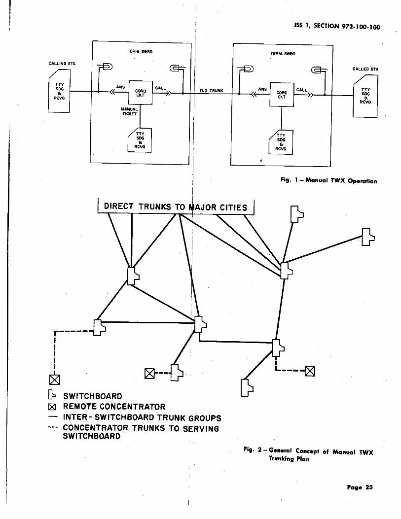
CALLING STA
TTY SDG
8 RCVG
r-----I I I I I
~
ANS
ORIG SWBD
CORD CKT
MANUAL TICKET
(? SWITCHBOARD ~ REMOTE CONCENTRATOR
TLG TRUNK
INTER- SWITCHBOARD TRUNK GROUPS CONCENTRATOR TRUNKS TO SERVING SWITCHBOARD
ANS
ISS 1, SECTION 972-1 00-1 00
TERM.SWBD
CORD CKT
CALL
CALLED .STA
TTY SDG
8 RCVG
Fig. 1 - Manual TWX Operation
Fig. 2 - General Concept of Manual TWX Trunking Plan
Page 23

VOICE LOOP
g r---, . I SUB I . SET 1--- ~.VOICE . I DATA I LOOP ~ SET~--. I I
L--...J · r I I
REMOTE I EXCH I LOOP ---tlf
TWX SERVING OFFICE
I WIRE .I CENTER
I; OFfKE I :.g. r-:~l . . : . : TTY 1---~ I
MACH . J DATA L-_J . 1 SET 1
L---1.
TOLL OFFICE TOLL
· OFFICE r.;.... _____ ...;,.~ t-----1 MODIFIED ECHO .,__-4
SUPPRESSOR · r , L _______ ...J
I I 1 r I I I I I I
TWX SERVING OFFICE
I I. TWX SWITCHBOARD
I· ! ~.----------r-=--, l I Ll . 'DATAl ·'I· +-<~-,.~----------t SET I I I .-----4 I I I .l. ..L L .... _...J 1 r- --, r. ~ · 1 I ILTE~P:ET l I ~, ~ r---, I I _T_:J LT _ _J I I I I . I .L-----i ~::I I L------t-<f--...l----,....----1 I 'I
ISS 1, SECTION 972-1~100
I I I I I I I r---, a I l g I I 1----1 TTY L I DATA I MACH i SET ·t- . . .
L---' . .
---..;;_ NEW FACILITIES FOR DIAL TWX L_· -----· _. ___ L-~:_J
----- EXISTING FACILITIES ..
"•· 3- General Plan Of the Dial TWX Sy.tem
..... 24

TWX
AUTOMATIC TEST LINE
T l------4
REMOTE EXCHANGE TWX LOOP
TWX
TELEGRAPH TEST$JER
(MAffNEOl·
TELEPHONE a TWX
CENT. OFF.
TELEPHONE CENT. OFF.
TELEPHONE REP SERV
iNTEROFFICE TRUNKS
TELEPHONE a TWX
CENT. OFF.
LOCAL TWX LOOP
ISS 1, SECTION 972·100-100
TELEPHONE REP SERV
I TWX I TWX STATION
T ·TELEPHONE
REP SERV
TELEPHONE STATION
Fig. 4 ... Iaale Maintenance Arrangements ,., · Dial TWX Stations

Fig. 5- Data Set lOlA and Subscriber Set 689A Mounted on 28 KSR Teletypewriter
Fig. 5A- Data Set 101 A and Subscriber Set 691 A3 Associated with 15-Type Teletypewriter
Fig. 5 and 5A
Page 26

DC TTY PULSES AND CORRESPONDING AC FREQUENCIES
(START) (I) (2) (3) (4) ( 5) (STOP) MARK ----- ----.~ r-~-.,
SPACE----------'-· ---' '--------'
~ARK FREQUENCY r-r F1M 1270 CPS F2M 2225 CPS
ORIGINATING STATION M S M
--u-M S M
M --+ 12 70 fUlfUUlJ ,.-------1 ( Fl) 1------.,
.s---+ 1070
[
SPACE FREQUENCY ,___-----t· F1 S 1070 CPS
F2S 2025 CPS
TERMINATING STATION M S M M S M
rulfVUU 12 70 ---+ M --u-r-------1 ( F I) 1--------,
1070---+ s
Fig. 6- Data Set 101 A, Principle of Operation
Page 27

,..------., I I I I
I I _______ J
LOCAL CENTRAL OFFICS (WIRE CENTER)
* THESE EXCHANGE FACILITIES MAY INCLUDE VF REPEATERS OR CARRIER
I
N0.5 CROSSBAR
OFFICE
L --- -------L--.-------1
EXCHANGE FACILITIES ..-.---1 (MAY INCLUDE DLLC,
ODD TRUNKS
SF SIGNALING CIRCUITS . AND/OR CONCENTRAToR')
r-- -------~-----------1 ORIG : ONLY STEP-BY-STEP
OFFICE DIVIDED ACCESS TERM. 1------4 LINE (TERMINATING CIRCUIT ONLY CALLS ONLY
I I I
FOR DIAL TWX CUSTOMERS)
L------ - --·'---------.....1
ODD TRUNKS
DOD NETWORK
Fig. 7- Representative Arrangements of Subscriber Line Facilities ·
Page 28

f\t· I - swltc"boord Connect\on \nto th• Network
\SS \, SiC'tlON 972·1()0-100
OPER pQS\T\ON --41"l
AUX tORD P\LOT .,., •• /' /
\NCOtA\NG -~ TRUNK tAULT tA\SC MULT ~~:::l.t~:;~:f"~::.U..J2:lt::it---ll\fl:l'f TEST. LAMP
PLUGSIIELf
MULTI-CARD SULLET\N
JACKS
f\1· I ofld 9
Pat• 29

FROM ~WITCH OFFICE
TO SWITCH OFFICE
Fig. 10- Block Diagram of Switchboard Circuits
CORD s
TICKE BOX
T
LAMP
TYPE ANS TALK
TYPE CALL TALK
TEAM
s
" + 't +
• A-
SHE LF--t
ISS 1, SECTION 972-100-100
ANS CALL.
,.... 0 0
@ @ ~ loo 'i' ® (!) lCD ® @ ® I®
j.-POSITION DIVIDING
I L.INE I
6 7 8 9 101 I I 2 3 4 !5 0 0 0 0 0,0 0 0 0 0 0 0 0 0 OIO 0 0 0 0
rr:; 0 0 0 0 0 0 0 0 0 0 0 0 0 0 0 0 0 0 0
~ ¢ ¢ ¢ ¢ ¢ ¢ ¢ ¢ ¢
¢ ¢ ¢ ¢ ¢ ¢ ¢ ¢ ¢ ¢
¢ ¢ ¢ ¢ ¢ ¢ ¢ ¢ ¢ ¢
SI 6 L
CALCULAGRAPH
Fig. 11 - Plan VIew of the Switchboard Keyshelf
T w a.. 0 _. (I)
z -CD 11'1
0
~
z 11'1 ,... en
_fA
+ ~ NS PLIT ALL
_t A
~ ~ ux IG AMP A
1
Fig. 10 and 11
Page 30

ISS 1 I SECTION 972-1 00-1 00
r
I UNDIST I THE QUICK BROWN FOX JUMPED OVER Pf LAZY DOG 1 S THE QUICK BROWN FOX JUMPED OVER ~· LAZY DOG'S DIS 20 THE QUICK BROWN FOX JUMPED OVER LAZY DOG'S ~HE QtJlCK BROWN FOX JUMPED OVER :,LAZY DOG'S Dl:S l?AD ~ - .··' CK BROWN FOX JUMPED OVER ·LAZY OOG 1 S ~. '"····.·" .. 0.· K BROWN FOX JUMPED OVER ,LAZY DOG 1 S ' _.:ee 11 ) -. . . . · .'!RYRYRYRYRYRYRYR f
f.
BACK 1234567898 BACK 1234567890
BACK 1234567890 BACK 1234567890
BACK 1234567890 BACK 1234567890
FLIPt (2 Be11s)~ '._, BROWN FOX JUMPED OVER A iy'·LAZY DOG 1 S BACK 1234567 890
CK BROWN FOX JUMPED OVER A. LAZY DOG'S BACK 1234567890
'PJtAN OKt 'lJNX END
BROWN FOX JUMPED OVER A• LAZY DOG 1 S BACK 1234567890 BROWN FOX JUMPED OVER A! LAZY DOG 1 S BACK 1234567890
i BROWN FOX JUMPED OVER A!LAZY DOG'S BACK 1234567890 BROWN FOX JUMPED OVER A LAZY DOG'S BACK 1234567890 11)
• A 3-letter combination .will be used to identi.fY which A TL is being used. I
~xxxr XXX* SENDING SENDING
~ xxx)* SENDING xxx)* SENDING
~~~= SENDING SENDING
~~~= SENDING SENDING
~~~: SENDING SENDING
~~~= SENDING SENDING
t If the t:r~smission received from the outl~ng station is out of limits, the wording will be OUT LlM. ·
:1: FLIP m~ans that the outlying station shouli change from the originating to the answer mode.
I I
Fig. 12 - Sample Copy Obtained from Use of the Automatic Test Line
Page 31

ISS I, SICfiON 972-100-100
ORIGINATING STATION TERMINATING STATION
Att~dant depresses ORIGINATE button <t > I \ t
Data set presents off-hook condition to cent. off. (2) I t
Dial. tone received from cent. off. (3) I t
Attendant dials 7- or 10-digit number (4)j
t Switching links are set up over the DOD networkJ 1 Station ringer is operated <9> I
t t t Busy tone or I Audible ringing received (8) I Attendant depresses ANSWER button ( 1 0) I intercept report t t received (5) I Don't-answer I I Aud i b I e ringing ~-+- c 11 > I ceases Data set presents off-hook condition to cent. off.
condition t I I Data set introduces 1.4-second timed delay (12) I
I t Attendant cancels I Data set receives F2 mark (14) 1 Data set sends F2 mark (13)1 call by de.pressing t CLEAR button (b) I Data set times F2 for 1 second (15) J
1 Data set receives F1 mark c 18> 1 t t I Data set sends F1 mark (1b) and I I Data set times F1 for 1 second (1 9) I
Data set goesj then turns on TTY motor (17) I and then turns on TTY motor (20) on-hook ( 7) t
I Terminating sta identification received (22) 1 Attendant types stat ion identification (21) I + l Attendant types message (23) - - - _...,.__ --i Message received I :t
jAttendant depresses CLEAR button (24> 1 t
'Data set sends F1 space for 1 second (25) I and then goes on-hook I
I Data set I and then
receives F1 space for 1 second I goes on-hook (2b)
Fig. 13 - Flow Diagram of a TWX Connection Between Attended Stations
Page 32 32 ,., ••