g3907-8911-5 - kubota.com.au · afluid escaping from pinholes may be invisible. use a piece of...
TRANSCRIPT
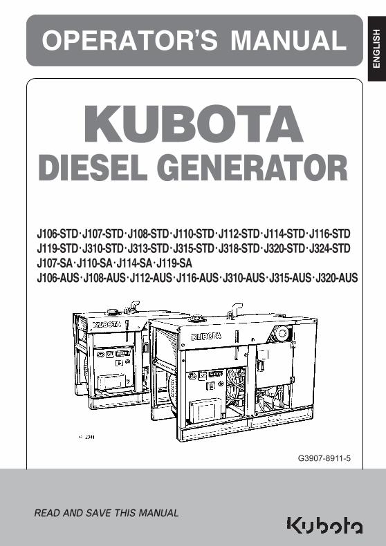
G3907-8911-5
EN
GLIS
H
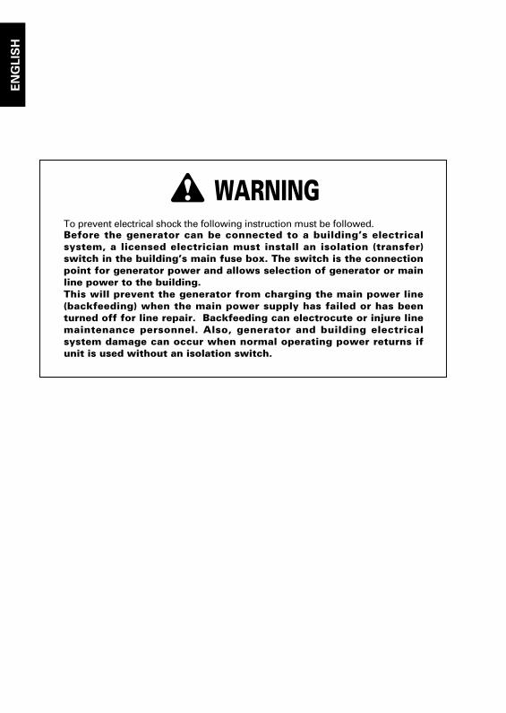
3 WARNINGTo prevent electrical shock the following instruction must be followed.Before the generator can be connected to a building’s electricalsystem, a licensed electrician must install an isolation (transfer)switch in the building’s main fuse box. The switch is the connectionpoint for generator power and allows selection of generator or mainline power to the building.This will prevent the generator from charging the main power line(backfeeding) when the main power supply has failed or has beenturned off for line repair. Backfeeding can electrocute or injure linemaintenance personnel. Also, generator and building electricalsystem damage can occur when normal operating power returns ifunit is used without an isolation switch.
EN
GLIS
H
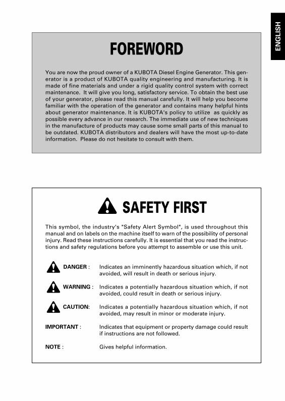
FOREWORDYou are now the proud owner of a KUBOTA Diesel Engine Generator. This gen-erator is a product of KUBOTA quality engineering and manufacturing. It ismade of fine materials and under a rigid quality control system with correctmaintenance. It will give you long, satisfactory service. To obtain the best useof your generator, please read this manual carefully. It will help you becomefamiliar with the operation of the generator and contains many helpful hintsabout generator maintenance. It is KUBOTA's policy to utilize as quickly aspossible every advance in our research. The immediate use of new techniquesin the manufacture of products may cause some small parts of this manual tobe outdated. KUBOTA distributors and dealers will have the most up-to-dateinformation. Please do not hesitate to consult with them.
3 SAFETY FIRSTThis symbol, the industry's "Safety Alert Symbol", is used throughout thismanual and on labels on the machine itself to warn of the possibility of personalinjury. Read these instructions carefully. It is essential that you read the instruc-tions and safety regulations before you attempt to assemble or use this unit.
3 DANGER : Indicates an imminently hazardous situation which, if notavoided, will result in death or serious injury.
3 WARNING : Indicates a potentially hazardous situation which, if notavoided, could result in death or serious injury.
3 CAUTION: Indicates a potentially hazardous situation which, if notavoided, may result in minor or moderate injury.
IMPORTANT : Indicates that equipment or property damage could resultif instructions are not followed.
NOTE : Gives helpful information.

G3907-8911-5.book Page 4 Thursday, February 16, 2012 6:17 PM
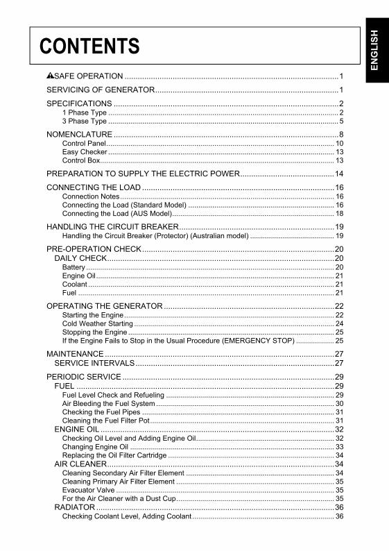
CONTENTS
EN
GL
ISH
SAFE OPERATION ..................................................................................................1
SERVICING OF GENERATOR....................................................................................1
SPECIFICATIONS .......................................................................................................21 Phase Type ................................................................................................................... 23 Phase Type ................................................................................................................... 5
NOMENCLATURE .......................................................................................................8Control Panel.................................................................................................................. 10Easy Checker ................................................................................................................. 13Control Box..................................................................................................................... 13
PREPARATION TO SUPPLY THE ELECTRIC POWER...........................................14
CONNECTING THE LOAD ........................................................................................16Connection Notes........................................................................................................... 16Connecting the Load (Standard Model) ......................................................................... 16Connecting the Load (AUS Model)................................................................................. 18
HANDLING THE CIRCUIT BREAKER.......................................................................19Handling the Circuit Breaker (Protector) (Australian model) .......................................... 19
PRE-OPERATION CHECK........................................................................................20DAILY CHECK........................................................................................................20
Battery ............................................................................................................................ 20Engine Oil ....................................................................................................................... 21Coolant ........................................................................................................................... 21Fuel ................................................................................................................................ 21
OPERATING THE GENERATOR ..............................................................................22Starting the Engine......................................................................................................... 22Cold Weather Starting .................................................................................................... 24Stopping the Engine ....................................................................................................... 25If the Engine Fails to Stop in the Usual Procedure (EMERGENCY STOP) ................... 25
MAINTENANCE .........................................................................................................27SERVICE INTERVALS...........................................................................................27
PERIODIC SERVICE .................................................................................................29FUEL ......................................................................................................................29
Fuel Level Check and Refueling .................................................................................... 29Air Bleeding the Fuel System ......................................................................................... 30Checking the Fuel Pipes ................................................................................................ 31Cleaning the Fuel Filter Pot............................................................................................ 31
ENGINE OIL ...........................................................................................................32Checking Oil Level and Adding Engine Oil..................................................................... 32Changing Engine Oil ...................................................................................................... 33Replacing the Oil Filter Cartridge ................................................................................... 34
AIR CLEANER........................................................................................................34Cleaning Secondary Air Filter Element .......................................................................... 34Cleaning Primary Air Filter Element ............................................................................... 35Evacuator Valve ............................................................................................................. 35For the Air Cleaner with a Dust Cup............................................................................... 35
RADIATOR .............................................................................................................36Checking Coolant Level, Adding Coolant....................................................................... 36
CONTENTSE
NG
LIS
H
Changing Coolant........................................................................................................... 37Remedies for quick decrease of coolant ........................................................................ 37Checking Radiator Hoses and Clamps .......................................................................... 38Precaution Overheating.................................................................................................. 38Cleaning Radiator Core (outside)................................................................................... 38Cleaning the Radiator..................................................................................................... 38Anti-freeze ...................................................................................................................... 38
BATTERY ...............................................................................................................39Battery Charging ............................................................................................................ 39Instructions for Long Term Storage................................................................................ 41Battery Boost Starting .................................................................................................... 41
ELECTRIC WIRING ...............................................................................................41PERIODIC SERVICING AND CLEANING OF THE GENERATOR........................42FUSE ......................................................................................................................44FAN BELT ..............................................................................................................45
Adjusting Fan Belt Tension ............................................................................................ 45
TRANSPORTING / STORAGE ..................................................................................46Transporting ................................................................................................................... 46Storage........................................................................................................................... 46
TROUBLESHOOTING ...............................................................................................47Generator ....................................................................................................................... 47Easy Checker ................................................................................................................. 48Engine ............................................................................................................................ 48
AUTOMATIC START/STOP UNIT (A S/S UNIT) .......................................................50
WIRING DIAGRAM ....................................................................................................51
1SAFE OPERATION
NG
LIS
H
SAFE OPERATION
E
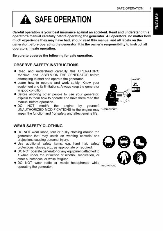
Careful operation is your best insurance against an accident. Read and understand thisoperator’s manual carefully before operating the generator. All operators, no matter howmuch experience they may have had, should read this manual and all labels on thegenerator before operating the generator. It is the owner's responsibility to instruct alloperators in safe operation.
Be sure to observe the following for safe operation.
OBSERVE SAFETY INSTRUCTIONS
ARead and understand carefully this OPERATOR'SMANUAL and LABELS ON THE GENERATOR beforeattempting to start and operate the generator.
A Learn how to operate and work safely. Know yourequipment and its limitations. Always keep the generatorin good condition.
ABefore allowing other people to use your generator,explain to them how to operate and have them read thismanual before operation.
ADO NOT modify the engine by yourself.UNAUTHORIZED MODIFICATIONS to the engine mayimpair the function and / or safety and affect engine life.
WEAR SAFETY CLOTHING
ADO NOT wear loose, torn or bulky clothing around thegenerator that may catch on working controls andprojections causing personal injury.
AUse additional safety items, e.g. hard hat, safetyprotections, gloves, etc., as appropriate or required.
ADO NOT operate generator or any equipment attached toit while under the influence of alcohol, medication, orother substances, or while fatigued.
ADO NOT wear radio or music headphones whileoperating the generator.
SAFE OPERATION2E
NG
LIS
H
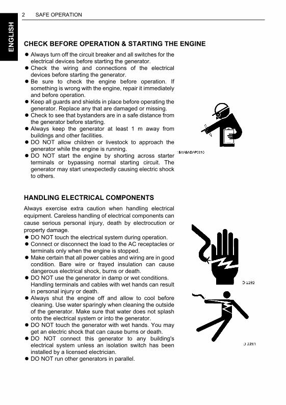
CHECK BEFORE OPERATION & STARTING THE ENGINE
AAlways turn off the circuit breaker and all switches for theelectrical devices before starting the generator.
ACheck the wiring and connections of the electricaldevices before starting the generator.
ABe sure to check the engine before operation. Ifsomething is wrong with the engine, repair it immediatelyand before operation.
AKeep all guards and shields in place before operating thegenerator. Replace any that are damaged or missing.
ACheck to see that bystanders are in a safe distance fromthe generator before starting.
AAlways keep the generator at least 1 m away frombuildings and other facilities.
ADO NOT allow children or livestock to approach thegenerator while the engine is running.
ADO NOT start the engine by shorting across starterterminals or bypassing normal starting circuit. Thegenerator may start unexpectedly causing electric shockto others.
HANDLING ELECTRICAL COMPONENTS
Always exercise extra caution when handling electricalequipment. Careless handling of electrical components cancause serious personal injury, death by electrocution orproperty damage.ADO NOT touch the electrical system during operation.AConnect or disconnect the load to the AC receptacles or
terminals only when the engine is stopped.AMake certain that all power cables and wiring are in good
condition. Bare wire or frayed insulation can causedangerous electrical shock, burns or death.
ADO NOT use the generator in damp or wet conditions.Handling terminals and cables with wet hands can resultin personal injury or death.
AAlways shut the engine off and allow to cool beforecleaning. Use water sparingly when cleaning the outsideof the generator. Make sure that water does not splashonto the electrical system or into the generator.
ADO NOT touch the generator with wet hands. You mayget an electric shock that can cause burns or death.
ADO NOT connect this generator to any building'selectrical system unless an isolation switch has beeninstalled by a licensed electrician.
ADO NOT run other generators in parallel.
3SAFE OPERATION
EN
GL
ISH
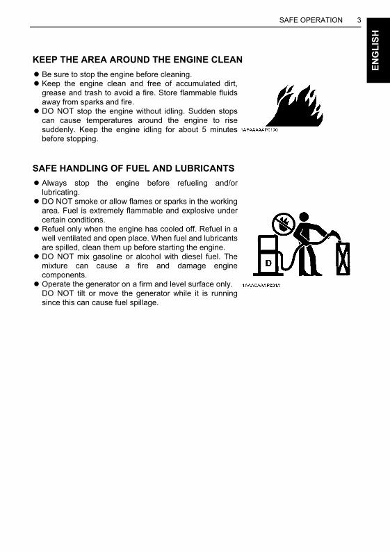
KEEP THE AREA AROUND THE ENGINE CLEAN
ABe sure to stop the engine before cleaning.AKeep the engine clean and free of accumulated dirt,
grease and trash to avoid a fire. Store flammable fluidsaway from sparks and fire.
ADO NOT stop the engine without idling. Sudden stopscan cause temperatures around the engine to risesuddenly. Keep the engine idling for about 5 minutesbefore stopping.
SAFE HANDLING OF FUEL AND LUBRICANTS
AAlways stop the engine before refueling and/orlubricating.
ADO NOT smoke or allow flames or sparks in the workingarea. Fuel is extremely flammable and explosive undercertain conditions.
ARefuel only when the engine has cooled off. Refuel in awell ventilated and open place. When fuel and lubricantsare spilled, clean them up before starting the engine.
ADO NOT mix gasoline or alcohol with diesel fuel. Themixture can cause a fire and damage enginecomponents.
AOperate the generator on a firm and level surface only.DO NOT tilt or move the generator while it is runningsince this can cause fuel spillage.
SAFE OPERATION4E
NG
LIS
H
EXHAUST GASES & FIRE PREVENTION
AEngine exhaust fumes can be very harmful if allowingthem to accumulate. Be sure to run the engine in a wellventilated place and where there are no people orlivestock near the generator.
ADO NOT operate the generator in a closed area such asinside houses, warehouses, tunnels, wells, ship holds,tanks, etc. or places without proper ventilation.
ADO NOT operate the generator where the building orother obstructions block off air circulation or whereexhaust gas can accumulate.
A The exhaust gas from the muffler is very hot. To preventa fire, DO NOT expose to dry grass, papers, oil and anyother combustible materials to exhaust gas. Also, keepthe engine and muffler clean at all times.
A To avoid fire, be alert for leaks of flammables from hosesand lines. Be sure to check for leaks from hoses or pipes,such as fuel and engine oil by following the maintenancecheck list.
A To avoid a fire, DO NOT short across power cables andwires.Check to see that all power cables and wiring are in goodcondition.
AKeep all power connections clean and tight. Bare wire orfrayed insulation can cause a dangerous electrical shockand personal injury.
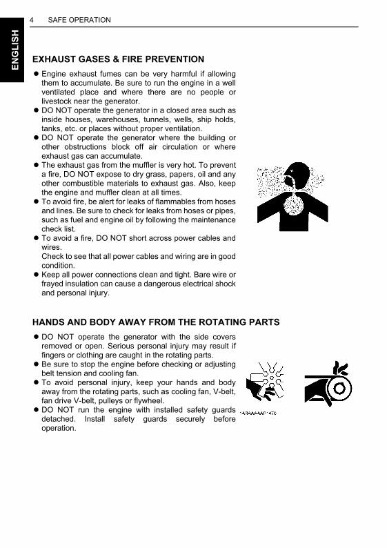
HANDS AND BODY AWAY FROM THE ROTATING PARTS
ADO NOT operate the generator with the side coversremoved or open. Serious personal injury may result iffingers or clothing are caught in the rotating parts.
ABe sure to stop the engine before checking or adjustingbelt tension and cooling fan.
A To avoid personal injury, keep your hands and bodyaway from the rotating parts, such as cooling fan, V-belt,fan drive V-belt, pulleys or flywheel.
ADO NOT run the engine with installed safety guardsdetached. Install safety guards securely beforeoperation.
5SAFE OPERATION
EN
GL
ISH
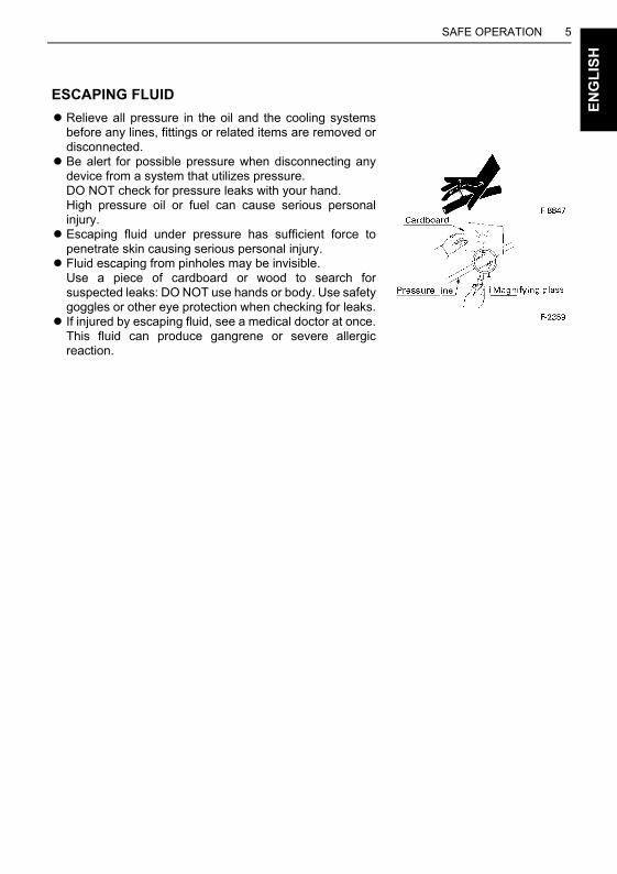
ESCAPING FLUID
ARelieve all pressure in the oil and the cooling systemsbefore any lines, fittings or related items are removed ordisconnected.
ABe alert for possible pressure when disconnecting anydevice from a system that utilizes pressure.DO NOT check for pressure leaks with your hand.High pressure oil or fuel can cause serious personalinjury.
AEscaping fluid under pressure has sufficient force topenetrate skin causing serious personal injury.
A Fluid escaping from pinholes may be invisible.Use a piece of cardboard or wood to search forsuspected leaks: DO NOT use hands or body. Use safetygoggles or other eye protection when checking for leaks.
A If injured by escaping fluid, see a medical doctor at once.This fluid can produce gangrene or severe allergicreaction.
SAFE OPERATION6E
NG
LIS
H
CAUTIONS AGAINST BURNS & BATTERY EXPLOSION
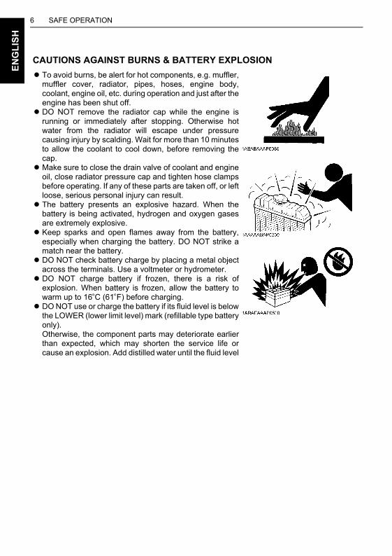
A To avoid burns, be alert for hot components, e.g. muffler,muffler cover, radiator, pipes, hoses, engine body,coolant, engine oil, etc. during operation and just after theengine has been shut off.
ADO NOT remove the radiator cap while the engine isrunning or immediately after stopping. Otherwise hotwater from the radiator will escape under pressurecausing injury by scalding. Wait for more than 10 minutesto allow the coolant to cool down, before removing thecap.
AMake sure to close the drain valve of coolant and engineoil, close radiator pressure cap and tighten hose clampsbefore operating. If any of these parts are taken off, or leftloose, serious personal injury can result.
A The battery presents an explosive hazard. When thebattery is being activated, hydrogen and oxygen gasesare extremely explosive.
AKeep sparks and open flames away from the battery,especially when charging the battery. DO NOT strike amatch near the battery.
ADO NOT check battery charge by placing a metal objectacross the terminals. Use a voltmeter or hydrometer.
ADO NOT charge battery if frozen, there is a risk ofexplosion. When battery is frozen, allow the battery towarm up to 16 C (61 F) before charging.
ADO NOT use or charge the battery if its fluid level is belowthe LOWER (lower limit level) mark (refillable type batteryonly). Otherwise, the component parts may deteriorate earlierthan expected, which may shorten the service life orcause an explosion. Add distilled water until the fluid level
7SAFE OPERATION
EN
GL
ISH
CONDUCTING SAFETY CHECKS & MAINTENANCE
AKnow how to stop the generator quickly, and understandoperation of all the controls. DO NOT permit anyone tooperate the generator without proper instruction.
AWhen checking engine or servicing, place the generatorin an open area and level ground. DO NOT work onanything that is supported ONLY by lift jacks or a hoist.Always use blocks or safety stands to support thegenerator before servicing.
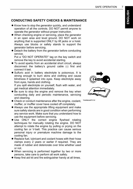
ADetach the battery from the generator before conductingservice. Put a “DO NOT OPERATE!” tag on the key switch andremove the key to avoid accidental starting.
A To avoid sparks from an accidental short circuit, alwaysdisconnect the battery’s ground cable (-) first andconnect it last.
ASulfuric acid in battery electrolyte is poisonous. It isstrong enough to burn skins and clothing and causeblindness if splashed into eyes. Keep electrolyte awayfrom eyes, hands and clothing.If you spill electrolyte on yourself, flush with water, andget medical attention immediately.
ABe sure to stop the engine and remove the key whenconducting daily and periodic maintenance, servicingand cleaning.
ACheck or conduct maintenance after the engine, coolant,muffler, or muffler cover have cooled off completely.
AAlways use the appropriate lifting equipment and makesure safety stands are in good condition when performingany service work. Make sure that you understand how touse the equipment before servicing.
AUse ONLY the correct engine flywheel rotatingtechniques for manually rotating the engine. DO NOTattempt to rotate the engine by pulling or prying on thecooling fan or V-belt. This practice can cause seriouspersonal injury or premature machine damage to thecooling fan.
AReplace fuel, lubricant and coolant hoses with their hoseclamps every 2 years or earlier if required. They aremade of rubber and deteriorate over time whether usedor not.
AWhen servicing is performed together by two or morepersons, take care to perform all work safely.
AKeep first aid kit and fire extinguisher handy at all times.
SAFE OPERATION8E
NG
LIS
H
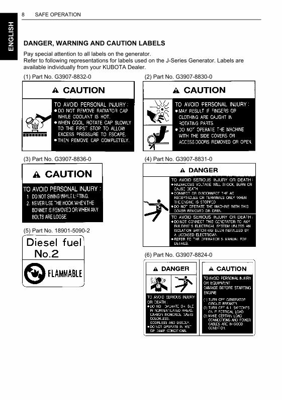
DANGER, WARNING AND CAUTION LABELS
Pay special attention to all labels on the generator.Refer to following representations for labels used on the J-Series Generator. Labels areavailable individually from your KUBOTA Dealer.
(1) Part No. G3907-8832-0 (2) Part No. G3907-8830-0
(3) Part No. G3907-8836-0 (4) Part No. G3907-8831-0
(5) Part No. 18901-5090-2
(6) Part No. G3907-8824-0
9SAFE OPERATION
EN
GL
ISH
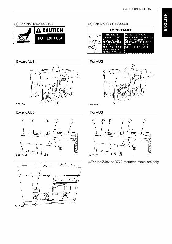
(7) Part No. 18620-8806-0 (8) Part No. G3907-8833-0
For the Z482 or D722-mounted machines only.

SAFE OPERATION10E
NG
LIS
H
1. Keep danger, warning and caution labels clean and free from obstructing material.2. Clean danger, warning and caution labels with soap and water, dry with a soft cloth.3. Replace damaged or missing danger, warning and caution labels with new labels from your
local KUBOTA Dealer.4. If a component with danger, warning and caution label(s) affixed is replaced with new part,
make sure new label(s) is (are) attached in the same location(s) as the replaced component.5. Mount new danger, warning and caution labels by applying on a clean dry surface and
pressing any bubbles to outside edge.
CARE OF DANGER, WARNING AND CAUTION LABELS
1SERVICING OF GENERATOR
NG
LIS
H
SERVICING OF GENERATOR
E
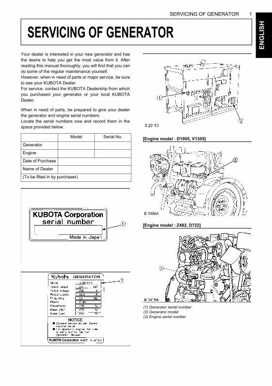
Your dealer is interested in your new generator and hasthe desire to help you get the most value from it. Afterreading this manual thoroughly, you will find that you cando some of the regular maintenance yourself.However, when in need of parts or major service, be sureto see your KUBOTA Dealer.For service, contact the KUBOTA Dealership from whichyou purchased your generator or your local KUBOTADealer.
When in need of parts, be prepared to give your dealerthe generator and engine serial numbers.Locate the serial numbers now and record them in thespace provided below.
[Engine model : D1005, V1305]
[Engine model : Z482, D722]
Model Serial No.
Generator
Engine
Date of Purchase
Name of Dealer
(To be filled in by purchaser)
(1) Generator serial number(2) Generator model(3) Engine serial number
2 SPECIFICATIONSE
NG
LIS
H
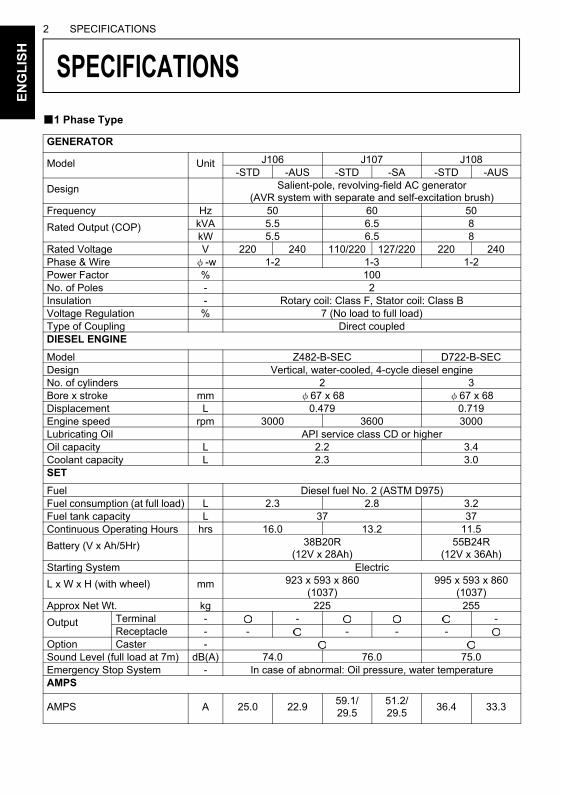
SPECIFICATIONS
MOKUJIYOUB1 Phase TypeGENERATOR
Model Unit J106 J107 J108-STD -AUS -STD -SA -STD -AUS
Design Salient-pole, revolving-field AC generator (AVR system with separate and self-excitation brush)
Frequency Hz 50 60 50
Rated Output (COP) kVA 5.5 6.5 8kW 5.5 6.5 8
Rated Voltage V 220 240 110/220 127/220 220 240Phase & Wire φ-w 1-2 1-3 1-2Power Factor % 100No. of Poles - 2Insulation - Rotary coil: Class F, Stator coil: Class BVoltage Regulation % 7 (No load to full load)Type of Coupling Direct coupledDIESEL ENGINE
Model Z482-B-SEC D722-B-SECDesign Vertical, water-cooled, 4-cycle diesel engineNo. of cylinders 2 3Bore x stroke mm φ67 x 68 φ67 x 68Displacement L 0.479 0.719Engine speed rpm 3000 3600 3000Lubricating Oil API service class CD or higherOil capacity L 2.2 3.4Coolant capacity L 2.3 3.0SET
Fuel Diesel fuel No. 2 (ASTM D975)Fuel consumption (at full load) L 2.3 2.8 3.2Fuel tank capacity L 37 37Continuous Operating Hours hrs 16.0 13.2 11.5
Battery (V x Ah/5Hr) 38B20R (12V x 28Ah)
55B24R (12V x 36Ah)
Starting System Electric
L x W x H (with wheel) mm 923 x 593 x 860(1037)
995 x 593 x 860 (1037)
Approx Net Wt. kg 225 255
Output Terminal - - -Receptacle - - - - -
Option Caster -Sound Level (full load at 7m) dB(A) 74.0 76.0 75.0Emergency Stop System - In case of abnormal: Oil pressure, water temperatureAMPS
AMPS A 25.0 22.959.1/29.5
51.2/29.5
36.4 33.3
3SPECIFICATIONS
EN
GL
ISH
GENERATOR
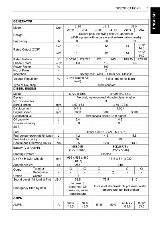
Model Unit J110 J112 J114-STD -SA -STD -AUS -STD -SA
Design Salient-pole, revolving-field AC generator (AVR system with separate and self-excitation brush)
Frequency Hz 60 50 60
Rated Output (COP)kVA 10 12 14 11.5/
14.0
kW 10 12 14 11.5/14.0
Rated Voltage V 110/220 127/220 220 240 110/220 127/220Phase & Wire φ-w 1-3 1-2 1-3Power Factor % 100No. of Poles - 2Insulation - Rotary coil: Class F, Stator coil: Class B
Voltage Regulation % 7 (No load to full load)
8 (No load to full load)
Type of Coupling Direct coupledDIESEL ENGINE
Model D722-B-SEC D1005-BG-SECDesign Vertical, water-cooled, 4-cycle diesel engineNo. of cylinders 3Bore x stroke mm φ67 x 68 φ76 x 73.6Displacement L 0.719 1.001Engine speed rpm 3600 3000 3600Lubricating Oil API service class CD or higherOil capacity L 3.4 4.3Coolant capacity L 3.0 3.3SET
Fuel Diesel fuel No. 2 (ASTM D975)Fuel consumption (at full load) L 4.2 4.5 5.8Fuel tank capacity L 37 79Continuous Operating Hours hrs 8.5 17.0 13.5
Battery (V x Ah/5Hr) 55B24R (12V x 36Ah)
80D26R(S) (12V x 55Ah)
Starting System Electric
L x W x H (with wheel) mm 995 x 593 x 860 (1037)
1215 x 611 x 922
Approx Net Wt. kg 255 340
Output Terminal - -Receptacle - - - - - -
Option Caster - -Sound Level (full load at 7m) dB(A) 76.5 76.5 81.0
Emergency Stop System -
In case of abnormal: Oil
pressure, water temperature
In case of abnormal: Oil pressure, water temperature, fan belt broken
AMPS
AMPS A90.9/45.5
78.7/45.5
54.5 50.063.6 x 2
/63.690.6/63.6
4 SPECIFICATIONSE
NG
LIS
H
GENERATOR
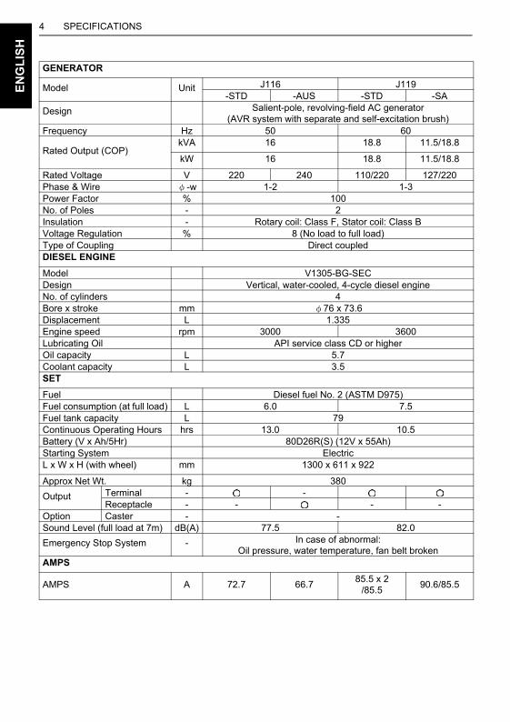
Model Unit J116 J119-STD -AUS -STD -SA
Design Salient-pole, revolving-field AC generator (AVR system with separate and self-excitation brush)
Frequency Hz 50 60
Rated Output (COP)kVA 16 18.8 11.5/18.8
kW 16 18.8 11.5/18.8
Rated Voltage V 220 240 110/220 127/220Phase & Wire φ-w 1-2 1-3Power Factor % 100No. of Poles - 2Insulation - Rotary coil: Class F, Stator coil: Class BVoltage Regulation % 8 (No load to full load)Type of Coupling Direct coupledDIESEL ENGINE
Model V1305-BG-SECDesign Vertical, water-cooled, 4-cycle diesel engineNo. of cylinders 4Bore x stroke mm φ76 x 73.6Displacement L 1.335Engine speed rpm 3000 3600Lubricating Oil API service class CD or higherOil capacity L 5.7Coolant capacity L 3.5SET
Fuel Diesel fuel No. 2 (ASTM D975)Fuel consumption (at full load) L 6.0 7.5Fuel tank capacity L 79Continuous Operating Hours hrs 13.0 10.5Battery (V x Ah/5Hr) 80D26R(S) (12V x 55Ah) Starting System ElectricL x W x H (with wheel) mm 1300 x 611 x 922
Approx Net Wt. kg 380
Output Terminal - -Receptacle - - - -
Option Caster - -Sound Level (full load at 7m) dB(A) 77.5 82.0
Emergency Stop System - In case of abnormal: Oil pressure, water temperature, fan belt broken
AMPS
AMPS A 72.7 66.785.5 x 2
/85.590.6/85.5
5SPECIFICATIONS
EN
GL
ISH
B3 Phase Type
GENERATOR
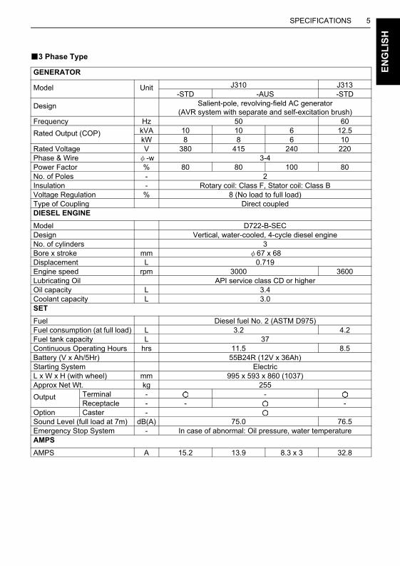
Model Unit J310 J313-STD -AUS -STD
Design Salient-pole, revolving-field AC generator (AVR system with separate and self-excitation brush)
Frequency Hz 50 60
Rated Output (COP) kVA 10 10 6 12.5kW 8 8 6 10
Rated Voltage V 380 415 240 220Phase & Wire φ-w 3-4Power Factor % 80 80 100 80No. of Poles - 2Insulation - Rotary coil: Class F, Stator coil: Class BVoltage Regulation % 8 (No load to full load)Type of Coupling Direct coupledDIESEL ENGINE
Model D722-B-SECDesign Vertical, water-cooled, 4-cycle diesel engineNo. of cylinders 3Bore x stroke mm φ67 x 68Displacement L 0.719Engine speed rpm 3000 3600Lubricating Oil API service class CD or higherOil capacity L 3.4Coolant capacity L 3.0SET
Fuel Diesel fuel No. 2 (ASTM D975)Fuel consumption (at full load) L 3.2 4.2Fuel tank capacity L 37Continuous Operating Hours hrs 11.5 8.5Battery (V x Ah/5Hr) 55B24R (12V x 36Ah)Starting System ElectricL x W x H (with wheel) mm 995 x 593 x 860 (1037)Approx Net Wt. kg 255
Output Terminal - -Receptacle - - -
Option Caster -Sound Level (full load at 7m) dB(A) 75.0 76.5Emergency Stop System - In case of abnormal: Oil pressure, water temperatureAMPS
AMPS A 15.2 13.9 8.3 x 3 32.8
6 SPECIFICATIONSE
NG
LIS
H
GENERATOR
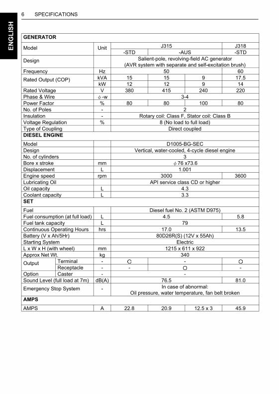
Model Unit J315 J318-STD -AUS -STD
Design Salient-pole, revolving-field AC generator (AVR system with separate and self-excitation brush)
Frequency Hz 50 60
Rated Output (COP) kVA 15 15 9 17.5kW 12 12 9 14
Rated Voltage V 380 415 240 220Phase & Wire φ-w 3-4Power Factor % 80 80 100 80No. of Poles - 2Insulation - Rotary coil: Class F, Stator coil: Class BVoltage Regulation % 8 (No load to full load)Type of Coupling Direct coupledDIESEL ENGINE
Model D1005-BG-SECDesign Vertical, water-cooled, 4-cycle diesel engineNo. of cylinders 3Bore x stroke mm φ76 x73.6Displacement L 1.001Engine speed rpm 3000 3600Lubricating Oil API service class CD or higherOil capacity L 4.3Coolant capacity L 3.3SET
Fuel Diesel fuel No. 2 (ASTM D975)Fuel consumption (at full load) L 4.5 5.8Fuel tank capacity L 79Continuous Operating Hours hrs 17.0 13.5Battery (V x Ah/5Hr) 80D26R(S) (12V x 55Ah)Starting System ElectricL x W x H (with wheel) mm 1215 x 611 x 922Approx Net Wt. kg 340
Output Terminal - -Receptacle - - -
Option Caster - -Sound Level (full load at 7m) dB(A) 76.5 81.0
Emergency Stop System - In case of abnormal:Oil pressure, water temperature, fan belt broken
AMPS
AMPS A 22.8 20.9 12.5 x 3 45.9

7SPECIFICATIONS
EN
GL
ISH
GENERATOR
Model Unit J320 J324-STD -AUS -STD
Design Salient-pole, revolving-field AC generator (AVR system with separate and self-excitation brush)
Frequency Hz 50 60
Rated Output (COP) kVA 20 20 10.8 23.5kW 16 16 10.8 18.8
Rated Voltage V 380 415 240 220Phase & Wire φ-w 3-4Power Factor % 80 80 100 80No. of Poles - 2Insulation - Rotary coil: Class F, Stator coil: Class BVoltage Regulation % 8 (No load to full load)Type of Coupling Direct coupledDIESEL ENGINE
Model V1305-BG-SECDesign Vertical, water-cooled, 4-cycle diesel engineNo. of cylinders 4Bore x stroke mm φ76 x73.6Displacement L 1.335Engine speed rpm 3000 3600Lubricating Oil API service class CD or higherOil capacity L 5.7Coolant capacity L 3.5SET
Fuel Diesel fuel No. 2 (ASTM D975)Fuel consumption (at full load) L 6.0 7.5Fuel tank capacity L 79Continuous Operating Hours hrs 13.0 10.5Battery (V x Ah/5Hr) 80D26R(S) (12V x 55Ah)Starting System ElectricL x W x H (with wheel) mm 1300 x 611 x 922Approx Net Wt. kg 380
Output Terminal - -Receptacle - - -
Option Caster - -Sound Level (full load at 7m) dB(A) 77.5 82.0
Emergency Stop System - In case of abnormal: Oil pressure, water temperature, fan belt broken
AMPS
AMPS A 30.4 27.8 15 x 3 61.7
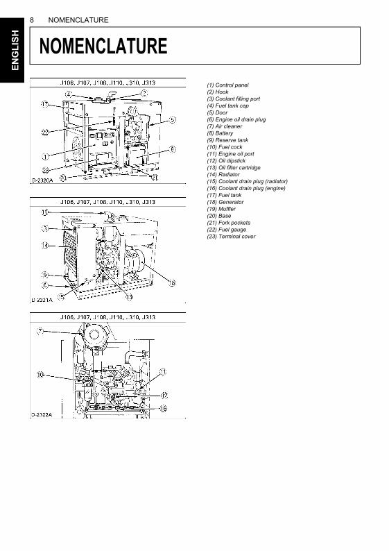
8 NOMENCLATUREE
NG
LIS
H
NOMENCLATURE
MOKUJIYOU(1) Control panel(2) Hook(3) Coolant filling port(4) Fuel tank cap(5) Door(6) Engine oil drain plug(7) Air cleaner(8) Battery(9) Reserve tank(10) Fuel cock(11) Engine oil port(12) Oil dipstick(13) Oil filter cartridge(14) Radiator(15) Coolant drain plug (radiator)(16) Coolant drain plug (engine)(17) Fuel tank(18) Generator(19) Muffler(20) Base(21) Fork pockets(22) Fuel gauge(23) Terminal cover
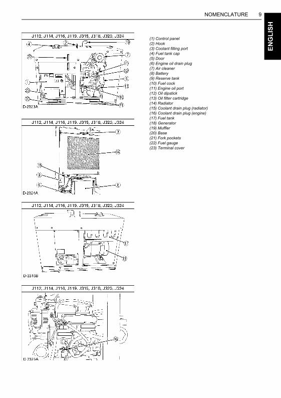
9NOMENCLATURE
EN
GL
ISH
(1) Control panel(2) Hook(3) Coolant filling port(4) Fuel tank cap(5) Door(6) Engine oil drain plug(7) Air cleaner(8) Battery(9) Reserve tank(10) Fuel cock(11) Engine oil port(12) Oil dipstick(13) Oil filter cartridge(14) Radiator(15) Coolant drain plug (radiator)(16) Coolant drain plug (engine)(17) Fuel tank(18) Generator(19) Muffler(20) Base(21) Fork pockets(22) Fuel gauge(23) Terminal cover
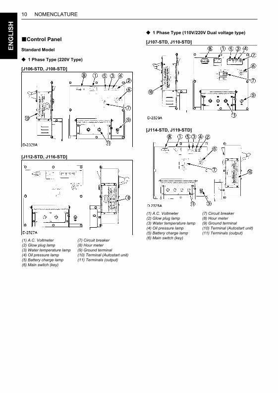
NOMENCLATURE10E
NG
LIS
H
BControl Panel
Standard Model
C 1 Phase Type (220V Type)
[J106-STD, J108-STD]
[J112-STD, J116-STD]
C 1 Phase Type (110V/220V Dual voltage type)
[J107-STD, J110-STD]
[J114-STD, J119-STD]
(1) A.C. Voltmeter(2) Glow plug lamp(3) Water temperature lamp(4) Oil pressure lamp(5) Battery charge lamp(6) Main switch (key)
(7) Circuit breaker(8) Hour meter(9) Ground terminal(10) Terminal (Autostart unit)(11) Terminals (output)
(1) A.C. Voltmeter(2) Glow plug lamp(3) Water temperature lamp(4) Oil pressure lamp(5) Battery charge lamp(6) Main switch (key)
(7) Circuit breaker(8) Hour meter(9) Ground terminal(10) Terminal (Autostart unit)(11) Terminals (output)
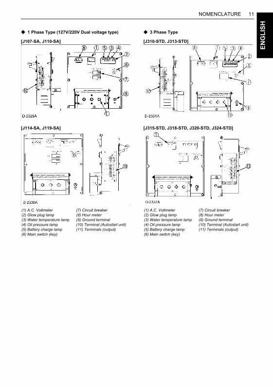
11NOMENCLATURE
EN
GL
ISH
C 1 Phase Type (127V/220V Dual voltage type)
[J107-SA, J110-SA]
[J114-SA, J119-SA]
C 3 Phase Type
[J310-STD, J313-STD]
[J315-STD, J318-STD, J320-STD, J324-STD]
(1) A.C. Voltmeter(2) Glow plug lamp(3) Water temperature lamp(4) Oil pressure lamp(5) Battery charge lamp(6) Main switch (key)
(7) Circuit breaker(8) Hour meter(9) Ground terminal(10) Terminal (Autostart unit)(11) Terminals (output)
(1) A.C. Voltmeter(2) Glow plug lamp(3) Water temperature lamp(4) Oil pressure lamp(5) Battery charge lamp(6) Main switch (key)
(7) Circuit breaker(8) Hour meter(9) Ground terminal(10) Terminal (Autostart unit)(11) Terminals (output)
NOMENCLATURE12E
NG
LIS
H
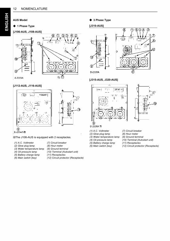
AUS Model
C 1 Phase Type
[J106-AUS, J108-AUS]
[J112-AUS, J116-AUS]
The J106-AUS is equipped with 2 receptacles.
C 3 Phase Type
[J310-AUS]
[J315-AUS, J320-AUS]
(1) A.C. Voltmeter(2) Glow plug lamp(3) Water temperature lamp(4) Oil pressure lamp(5) Battery charge lamp(6) Main switch (key)
(7) Circuit breaker(8) Hour meter(9) Ground terminal(10) Terminal (Autostart unit)(11) Receptacles(12) Circuit protector (Receptacle)
(1) A.C. Voltmeter(2) Glow plug lamp(3) Water temperature lamp(4) Oil pressure lamp(5) Battery charge lamp(6) Main switch (key)
(7) Circuit breaker(8) Hour meter(9) Ground terminal(10) Terminal (Autostart unit)(11) Receptacles(12) Circuit protector (Receptacle)
13NOMENCLATURE
EN
GL
ISH
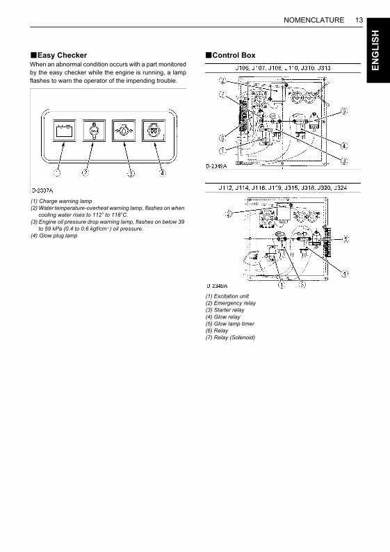
BEasy CheckerWhen an abnormal condition occurs with a part monitoredby the easy checker while the engine is running, a lampflashes to warn the operator of the impending trouble.
BControl Box
(1) Charge warning lamp(2) Water temperature-overheat warning lamp, flashes on when cooling water rises to 112 to 118 C.(3) Engine oil pressure drop warning lamp, flashes on below 39 to 59 kPa (0.4 to 0.6 kgf/cm ) oil pressure.(4) Glow plug lamp
(1) Excitation unit(2) Emergency relay(3) Starter relay(4) Glow relay(5) Glow lamp timer(6) Relay(7) Relay (Solenoid)
14 PREPARATION TO SUPPLY THE ELECTRIC POWERE
NG
LIS
H
PREPARATION TO SUPPLY THE ELECTRIC POWER
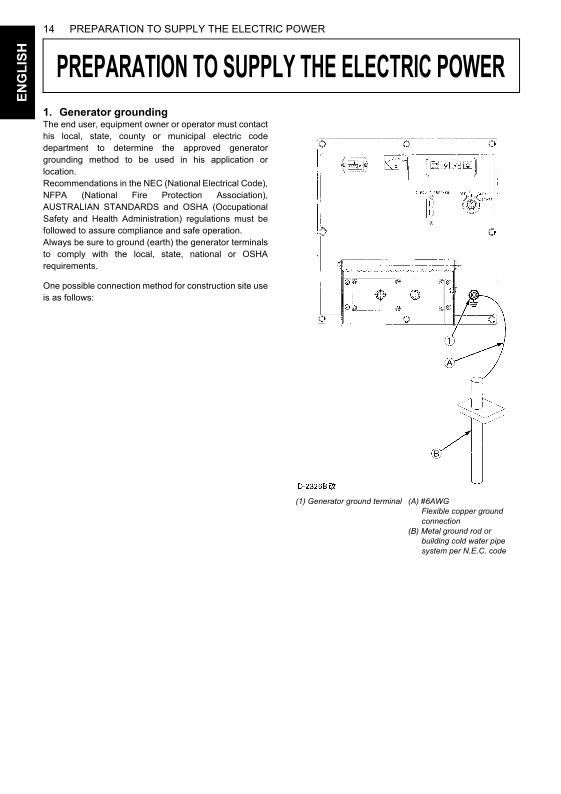
1. Generator groundingThe end user, equipment owner or operator must contacthis local, state, county or municipal electric codedepartment to determine the approved generatorgrounding method to be used in his application orlocation.Recommendations in the NEC (National Electrical Code),NFPA (National Fire Protection Association),AUSTRALIAN STANDARDS and OSHA (OccupationalSafety and Health Administration) regulations must befollowed to assure compliance and safe operation.Always be sure to ground (earth) the generator terminalsto comply with the local, state, national or OSHArequirements.One possible connection method for construction site useis as follows:
(1) Generator ground terminal (A) #6AWG Flexible copper ground connection(B) Metal ground rod or building cold water pipe system per N.E.C. code
15PREPARATION TO SUPPLY THE ELECTRIC POWER
EN
GL
ISH
2. Recommended capacity of electricaldevices
APPLICATION RANGEYou can operate the J-series generator in the followingrange.
A Keep an inverter load below 50% of the generatorcapacity.
A Make sure that total active mercury lamp load is below30% or so of the generator capacity. Turn on themercury lamps one by one. Be careful not to turn offthe lamps and on again immediately. The generatorvoltage may rise to extremely high levels and the AVRmay get damaged.
A Before turning on the lamps again, wait for 10 minutesor so until the lamps cool down enough.
A The data shown above is only a guideline toapproximate load capacities and may vary fromgenerator model to generator model, with differenttypes of loads at rated outputs. These values may bedifferent from actual applications because of the inputcharacteristics peculiar to each load.
A Connecting a motor.When connecting to a line starting motor, thesegenerators may be used to start a submerged pump of3.7kW, 5.5kW, 7.5kW (three phase). When startingthe motor, the voltage drops immediately. The circuitmay be opened if an electromagnetic switch isconnected to the same circuit. When connecting twomotors or more, make sure the total current capacityof the motors does not exceed the total rated current.
A Connecting to lights and electric heaters.When connecting to lights or electric heaters, thegenerator can be used up to the rated capacity. Whenusing a single phase, it can be used up to the ratedcurrent.
A Power factor calculations.The power factor calculation is used to determineinput of the electrical devices.
Power factors of commonly used devices are listed in thefollowing table.
A Ordinarily, a motor is rated in kW. This does not referto motor output.
A If a lighting system is employed together with sometypes of computers and inverter air-conditioners and/or the regulated power supply for TV sets, the lightsmight suffer flickering. This phenomenon does notindicate a fault of the generator: it is caused by poormatching between the above-mentioned regulatedpower supply and the generator's automatic voltageregulator. In such a case, modify the load combinationto eliminate the flickering.
TypicalApparatus Light and
heatersCommutator
motorInduction
motorJ106 5.5 kW 2.8 kW 0.8 kW
3.3 kW4.0 kW5.0 kW6.0 kW7.0 kW8.0 kW9.4 kW5.0 kW6.3 kW7.5 kW8.8 kW
10.0 kW11.8 kW
0.8 kW1.2 kW1.6 kW1.6 kW2 kW
2.4 kW2.4 kW3.7 kW3.7 kW4.4 kW5.5 kW5.9 kW7.4 kW
6.5 kW8 kW
10 kW12 kW14 kW16 kW
18.8 kW8 kW
10 kW12 kW14 kW16 kW
18.8 kW
J107J108J110J112J114J116J119J310J313J315J318J320J324
AC devicesElectric power (W) = Voltage (V) Current (A) Power factor
Load type Power factorSingle-phase induction motors 0.4 to 0.753-phase induction motors 0.65 to 0.85Electric heaters, incandescentlamps 1.0
AC arc welder 0.4 to 0.6
Commutator motor 0.8 to 0.95Fluorescent lamps, mercury lamps 0.4 to 0.9
Motor input (kVA) Motor output (kW)
Motor efficiency power factor=
16 CONNECTING THE LOADE
NG
LIS
H
CONNECTING THE LOAD
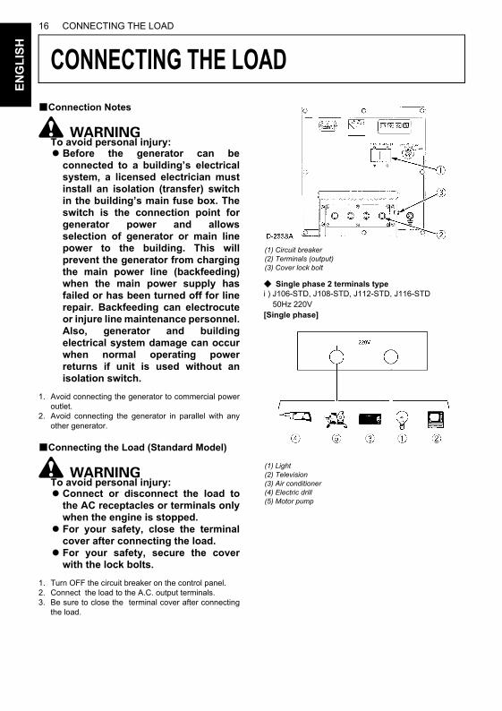
MOKUJIYOUBConnection Notes
To avoid personal injury:ABefore the generator can be
connected to a building’s electricalsystem, a licensed electrician mustinstall an isolation (transfer) switchin the building’s main fuse box. Theswitch is the connection point forgenerator power and allowsselection of generator or main linepower to the building. This willprevent the generator from chargingthe main power line (backfeeding)when the main power supply hasfailed or has been turned off for linerepair. Backfeeding can electrocuteor injure line maintenance personnel.Also, generator and buildingelectrical system damage can occurwhen normal operating powerreturns if unit is used without anisolation switch.
1. Avoid connecting the generator to commercial poweroutlet.
2. Avoid connecting the generator in parallel with anyother generator.
BConnecting the Load (Standard Model)
To avoid personal injury:AConnect or disconnect the load to
the AC receptacles or terminals onlywhen the engine is stopped.
AFor your safety, close the terminalcover after connecting the load.
AFor your safety, secure the coverwith the lock bolts.
1. Turn OFF the circuit breaker on the control panel.2. Connect the load to the A.C. output terminals.3. Be sure to close the terminal cover after connecting
the load.
C Single phase 2 terminals typei ) J106-STD, J108-STD, J112-STD, J116-STD 50Hz 220V[Single phase]
(1) Circuit breaker(2) Terminals (output)(3) Cover lock bolt
(1) Light (2) Television (3) Air conditioner(4) Electric drill(5) Motor pump
17CONNECTING THE LOAD
EN
GL
ISH
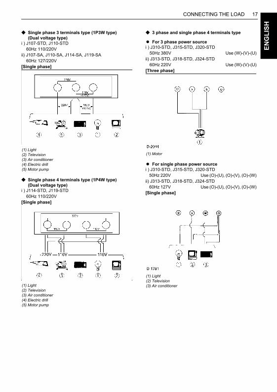
C Single phase 3 terminals type (1P3W type)(Dual voltage type)
i ) J107-STD, J110-STD 60Hz 110/220Vii) J107-SA, J110-SA, J114-SA, J119-SA 60Hz 127/220V[Single phase]
C Single phase 4 terminals type (1P4W type)(Dual voltage type)
i ) J114-STD, J119-STD 60Hz 110/220V[Single phase]
C 3 phase and single phase 4 terminals type
A For 3 phase power sourcei ) J310-STD, J315-STD, J320-STD 50Hz 380V Use (W)-(V)-(U)ii) J313-STD, J318-STD, J324-STD 60Hz 220V Use (W)-(V)-(U)[Three phase]
A For single phase power sourcei ) J310-STD, J315-STD, J320-STD 50Hz 220V Use (O)-(U), (O)-(V), (O)-(W)ii) J313-STD, J318-STD, J324-STD 60Hz 127V Use (O)-(U), (O)-(V), (O)-(W)[Single phase]
(1) Light (2) Television (3) Air conditioner(4) Electric drill(5) Motor pump
(1) Light (2) Television (3) Air conditioner(4) Electric drill(5) Motor pump
(1) Motor
(1) Light(2) Television(3) Air conditioner
CONNECTING THE LOAD18E
NG
LIS
H
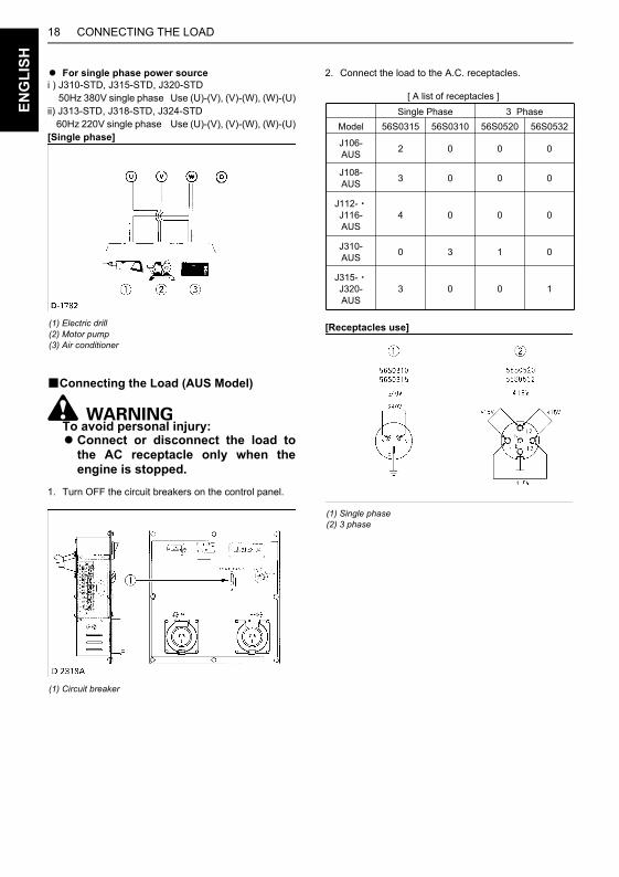
A For single phase power sourcei ) J310-STD, J315-STD, J320-STD 50Hz 380V single phase Use (U)-(V), (V)-(W), (W)-(U)ii) J313-STD, J318-STD, J324-STD 60Hz 220V single phase Use (U)-(V), (V)-(W), (W)-(U)[Single phase]
BConnecting the Load (AUS Model)
To avoid personal injury:AConnect or disconnect the load to
the AC receptacle only when theengine is stopped.
1. Turn OFF the circuit breakers on the control panel.
2. Connect the load to the A.C. receptacles.
[Receptacles use](1) Electric drill(2) Motor pump(3) Air conditioner
(1) Circuit breaker
(1) Single phase(2) 3 phase
[ A list of receptacles ]Single Phase 3 Phase
Model 56S0315 56S0310 56S0520 56S0532
J106-AUS 2 0 0 0
J108-AUS 3 0 0 0
J112-J116-AUS
4 0 0 0
J310-AUS 0 3 1 0
J315-J320-AUS
3 00 1
19HANDLING THE CIRCUIT BREAKER
NG
LIS
H
HANDLING THE CIRCUIT BREAKER
E
MOKUJIYOU
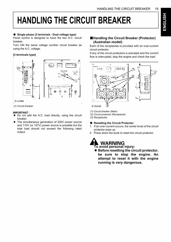
C Single phase (3 terminals - Dual voltage type)Panel control is designed to have the two A.C. circuitbreaker.Turn ON the same voltage number circuit breaker asusing the A.C. voltage.
[3 terminals type]
A Do not add the A.C. load directly, using the circuitbreaker.
A The simultaneous generation of 220V power sourceand 110V (or 127V) power source is possible but thetotal load should not exceed the following ratedoutput.
BHandling the Circuit Breaker (Protector) (Australian model)
Each of the receptacles is provided with an over-currentcircuit protector.If any of the circuit protectors is activated and the currentflow is interrupted, stop the engine and check the load.
C Resetting the Circuit Protector1. If an over-current occurs, the center knob of the circuit
protector pops up.2. Press down the knob to reset the circuit protector.
To avoid personal injury:ABefore resetting the circuit protector,
be sure to stop the engine. Anattempt to reset it with the enginerunning is very dangerous.
(1) Circuit breaker
(1) Circuit breaker (Main)(2) Circuit protector (Receptacle)(3) Receptacles
20 PRE-OPERATION CHECKE
NG
LIS
H
PRE-OPERATION CHECK
DAILY CHECKTo prevent problems from occurring, it is important toknow the condition of the generator. Always perform thefollowing check items before starting the generator.To avoid personal injury:ABefore checking or servicing the
generator, make sure it is on a levelsurface with the engine shut off.
C Check items-Check for oil and coolant leakage-Check cooling air inlet and outlet for obstructions or clogging-Check radiator fins for clogging-Check fan belt tension-Check engine oil level -Check coolant level-Check generator grounding-Refuel(See “FUEL” in “PERIODIC SERVICE” section.)-Care of danger, warning and caution labels (See "DANGER, WARNING AND CAUTION LABELS" in" SAFE OPERATION" section.)
To avoid personal injury from contactwith moving parts;ADO NOT open the door or generator
side cover while the engine isrunning.
ADo not touch muffler or exhaustpipes while they are hot; Severeburns could result.
BBatteryThe battery is shipped in dry, charged condition withoutelectrolyte.The battery must be charged properly before using for thefirst time.
To avoid the possibility of batteryexplosion:The battery comes in two types:refillable and non-refillable. For usingthe refillable type battery, follow theinstructions below.ADO NOT use or charge the battery if
the fluid level is below the LOWER(lower limit level) mark.Otherwise, the battery componentparts may deteriorate prematurely,shorten the battery's service life;which may cause an explosion.Immediately, add distilled water untilthe battery's fluid level comessomewhere between the UPPER andLOWER levels.
AKeep all sparks and flames awayfrom the battery and fuel tank. Abattery, especially when charging,will give off hydrogen and oxygengases which can explode and causeserious personal injury.
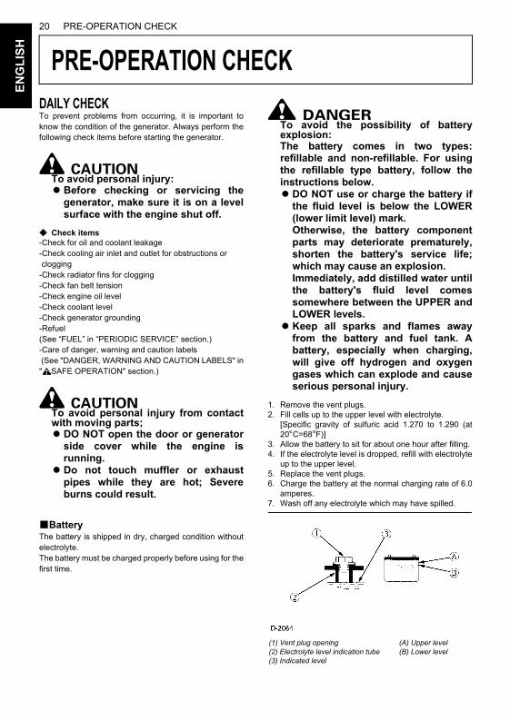
1. Remove the vent plugs.2. Fill cells up to the upper level with electrolyte.
[Specific gravity of sulfuric acid 1.270 to 1.290 (at20 C=68 F)]
3. Allow the battery to sit for about one hour after filling. 4. If the electrolyte level is dropped, refill with electrolyte
up to the upper level.5. Replace the vent plugs.6. Charge the battery at the normal charging rate of 6.0
amperes.7. Wash off any electrolyte which may have spilled.
(1) Vent plug opening (2) Electrolyte level indication tube (3) Indicated level
(A) Upper level(B) Lower level
21PRE-OPERATION CHECK
EN
GL
ISH
A The duration of dry charged efficiency, will decrease inproportion to the period of time elapsed after shipmentand during storage. To obtain the longest service lifeof the battery, it is necessary for the battery to becharged for a sufficient period of time. Continue tocharge until all cells are gassing freely, and thevoltage and specific gravity reading in all cells remainconstant for 3 or more successive readings taken at30 minute intervals.
A When the battery has been charged fully, the specificgravity of electrolyte should be 1.270 to 1.290 (at 20 C=68 F).
BEngine OilThe generator has been shipped without engine oil.Fill with oil to the correct level before attempting tostart the engine.
1. Place the machine on a level surface. 2. Remove the oil cap. 3. Add engine oil of grade CD or higher, up to the upper
mark on the oil level gauge.
A See "ENGINE OIL" in "PERIODIC SERVICE" sectionfor engine oil capacity and checking engine oil level.
BCoolant
To avoid personal injury:APlace the machine on a level surface.ADO NOT remove the radiator cap
while coolant is hot. When cool,rotate the radiator cap slowly to thefirst stop to allow excess pressure toescape. Then remove capcompletely.
1. Remove the radiator cap and fill with specified coolantuntil the coolant level is just below the port.
2. Fill with coolant to the “FULL” mark on the reservetank.
3. Securely tighten radiator cap and reserve tank cap.
A See "RADIATOR" in "PERIODIC SERVICE" sectionfor changing coolant.
BFuel
To avoid personal injury:ADO NOT refuel when engine is
running or hot.AAlways shut off the engine before
refueling.ADO NOT overfill fuel system. If any
fuel overflows, wipe it up completelybefore starting operation.
AWhen refueling, keep all flames,sparks and cigarettes away fromgenerator.
1. Always fill the fuel through the fuel tank strainer.2. Make sure that dirt or water does not enter the fuel
tank.3. Fill with Diesel fuel No.2-D (ASTMD975).4. Below 0 C (32 F) a mix of No.1-D and No.2-D is
acceptable.5. Fuel level is read by fuel gauge.
A If the fuel tank should empty completely causing theengine to stop, then the fuel system requires airbleeding after filling the tank and before restarting theengine.(See "Air Bleeding the Fuel System" in "PERIODICSERVICE" section.)
22 OPERATING THE GENERATORE
NG
LIS
H
OPERATING THE GENERATOR
MOKUJIYOUTo avoid personal injury:ARead " SAFE OPERATION" in the
front of this manual.ARead the danger, warning and
caution labels located on thegenerator.
ATo avoid the danger of exhaust fumepoisoning, do not operate the enginein a closed building without properventilation.
AAlways turn OFF the circuit breakerbefore starting the generator.
ATurn OFF all switches on theelectrical devices.
ACheck the wiring and connections ofthe electrical devices before startingthe machine.
ADO NOT touch the live parts duringoperation.
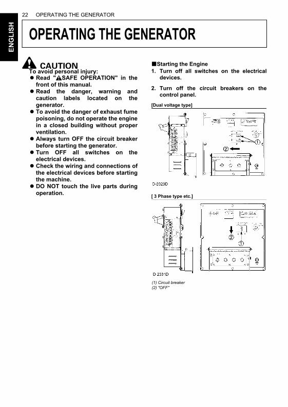
BStarting the Engine1. Turn off all switches on the electrical
devices.
2. Turn off the circuit breakers on thecontrol panel.
[Dual voltage type]
[ 3 Phase type etc.]
(1) Circuit breaker(2) "OFF"
23OPERATING THE GENERATOR
EN
GL
ISH
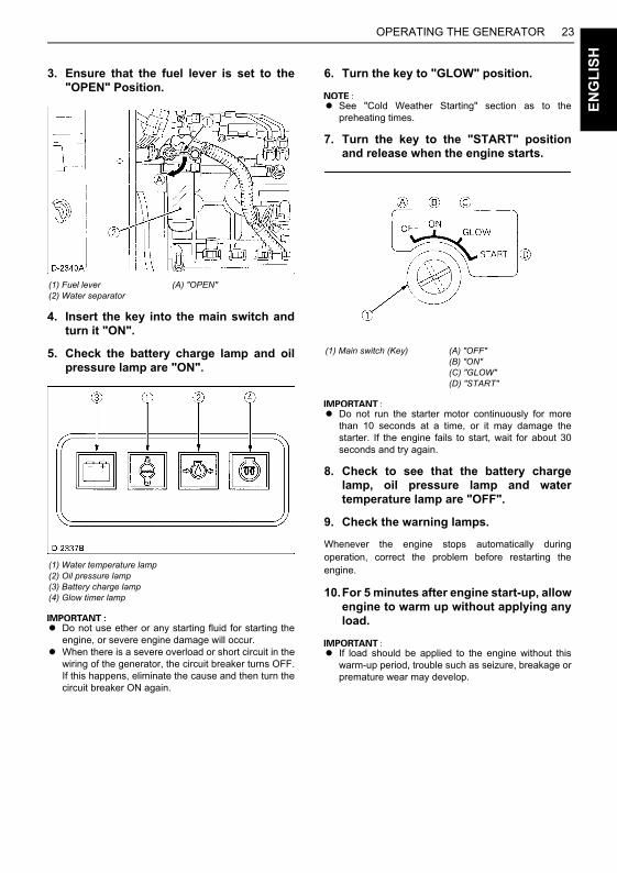
3. Ensure that the fuel lever is set to the"OPEN" Position.
4. Insert the key into the main switch andturn it "ON".
5. Check the battery charge lamp and oilpressure lamp are "ON".
A Do not use ether or any starting fluid for starting theengine, or severe engine damage will occur.
A When there is a severe overload or short circuit in thewiring of the generator, the circuit breaker turns OFF.If this happens, eliminate the cause and then turn thecircuit breaker ON again.
6. Turn the key to "GLOW" position.
A See "Cold Weather Starting" section as to thepreheating times.
7. Turn the key to the "START" positionand release when the engine starts.
A Do not run the starter motor continuously for morethan 10 seconds at a time, or it may damage thestarter. If the engine fails to start, wait for about 30seconds and try again.
8. Check to see that the battery chargelamp, oil pressure lamp and watertemperature lamp are "OFF".
9. Check the warning lamps.
Whenever the engine stops automatically duringoperation, correct the problem before restarting theengine.
10.For 5 minutes after engine start-up, allowengine to warm up without applying anyload.
A If load should be applied to the engine without thiswarm-up period, trouble such as seizure, breakage orpremature wear may develop.
(1) Fuel lever(2) Water separator
(A) "OPEN"
(1) Water temperature lamp(2) Oil pressure lamp(3) Battery charge lamp(4) Glow timer lamp
(1) Main switch (Key) (A) "OFF"(B) "ON"(C) "GLOW"(D) "START"
OPERATING THE GENERATOR24E
NG
LIS
H
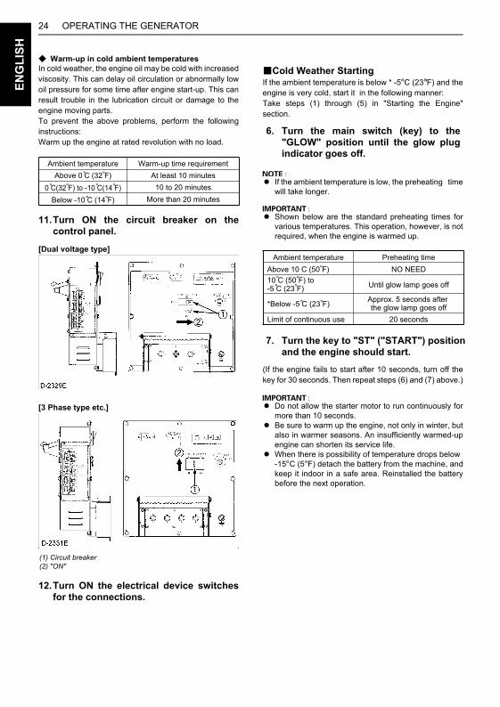
C Warm-up in cold ambient temperaturesIn cold weather, the engine oil may be cold with increasedviscosity. This can delay oil circulation or abnormally lowoil pressure for some time after engine start-up. This canresult trouble in the lubrication circuit or damage to theengine moving parts.To prevent the above problems, perform the followinginstructions:Warm up the engine at rated revolution with no load.
11.Turn ON the circuit breaker on thecontrol panel.
[Dual voltage type]
[3 Phase type etc.]
12.Turn ON the electrical device switchesfor the connections.
BCold Weather StartingIf the ambient temperature is below * -5 C (23 F) and theengine is very cold, start it in the following manner:Take steps (1) through (5) in "Starting the Engine"section.
A If the ambient temperature is low, the preheating timewill take longer.
A Shown below are the standard preheating times forvarious temperatures. This operation, however, is notrequired, when the engine is warmed up.
(If the engine fails to start after 10 seconds, turn off thekey for 30 seconds. Then repeat steps (6) and (7) above.)
A Do not allow the starter motor to run continuously formore than 10 seconds.
A Be sure to warm up the engine, not only in winter, butalso in warmer seasons. An insufficiently warmed-upengine can shorten its service life.
A When there is possibility of temperature drops below -15 C (5 F) detach the battery from the machine, andkeep it indoor in a safe area. Reinstalled the batterybefore the next operation.
(1) Circuit breaker(2) "ON"
Ambient temperature Warm-up time requirementAbove 0 C (32 F) At least 10 minutes
0 C(32 F) to -10 C(14 F) 10 to 20 minutes
Below -10 C (14 F) More than 20 minutes
6. Turn the main switch (key) to the"GLOW" position until the glow plugindicator goes off.
7. Turn the key to "ST" ("START") positionand the engine should start.
Ambient temperature Preheating timeAbove 10 C (50 F) NO NEED10 C (50 F) to -5 C (23 F) Until glow lamp goes off
*Below -5 C (23 F) Approx. 5 seconds after the glow lamp goes off
Limit of continuous use 20 seconds
25OPERATING THE GENERATOR
EN
GL
ISH
BStopping the Engine1. Turn OFF all electrical device switches
for connected loads.
2. Turn OFF the circuit breakers.
3. Allow the engine to run with no load forabout 5 minutes before stopping theengine completely.
4. Turn the main switch (key) to the "OFF"position.
5. Turn the fuel lever to the "CLOSE"position.
BIf the Engine Fails to Stop in the Usual Procedure (EMERGENCY STOP)
If the engine does not stop after turning the key switch to"OFF" position, take the following (emergency stop)procedure.
To avoid personal injury:AKeep your hands away from the
rotating parts, such as cooling fanand V-belt. Otherwise personal injurymay be caused when manipulatingthe engine stop lever.
1. Open the door, using the door knob.2. Turn the engine stop lever to "STOP" direction and
hold it for 5 to 10 seconds to shut off the engine.
[Engine model : Z482, D722]
[Engine model : D1005, V1305]
(1) Main switch (Key) (A) "OFF"
(1) Fuel lever(2) Filter bowl
(A) "CLOSE"
(1) Engine stop lever (A) "START"(B) "STOP"

OPERATING THE GENERATOR26E
NG
LIS
H
3. After stopping the engine, make sure that the door isclosed and the main switch (key) is at "OFF".
4. The following causes are possible for such unusualengine shut-off.Pinpoint and correct the cause of trouble.A Check for the stop solenoid.A Check to see if the battery has discharged too
much or is in trouble.A Check for disconnection of the battery terminals.
27MAINTENANCE
NG
LIS
H
MAINTENANCE
E
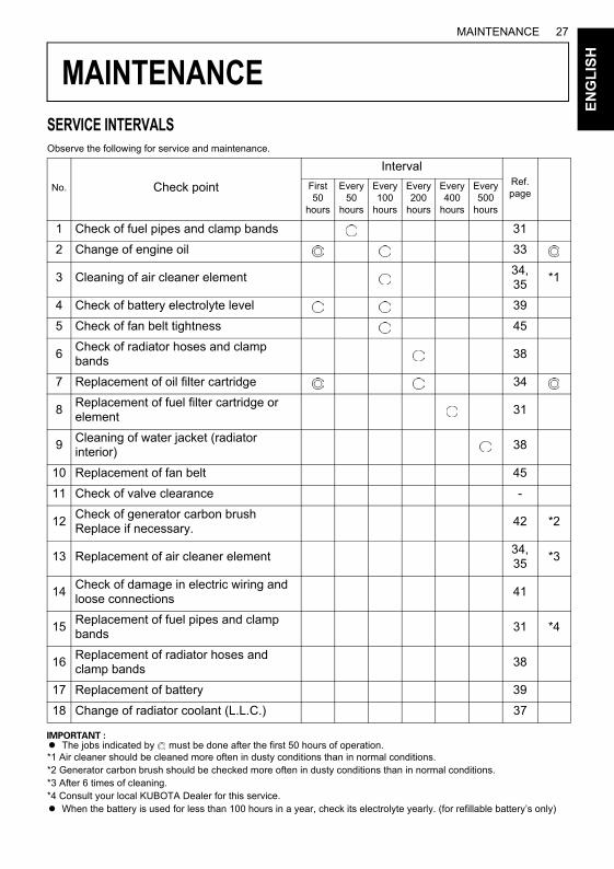
SERVICE INTERVALSObserve the following for service and maintenance.
A The jobs indicated by must be done after the first 50 hours of operation.*1 Air cleaner should be cleaned more often in dusty conditions than in normal conditions.*2 Generator carbon brush should be checked more often in dusty conditions than in normal conditions.*3 After 6 times of cleaning.*4 Consult your local KUBOTA Dealer for this service.A When the battery is used for less than 100 hours in a year, check its electrolyte yearly. (for refillable battery’s only)
No. Check point
IntervalRef. page
First 50
hours
Every 50
hours
Every 100
hours
Every 200
hours
Every 400
hours
Every 500
hours
1 Check of fuel pipes and clamp bands 31
2 Change of engine oil 33
3 Cleaning of air cleaner element34,35
*1
4 Check of battery electrolyte level 39
5 Check of fan belt tightness 45
6Check of radiator hoses and clamp bands
38
7 Replacement of oil filter cartridge 34
8Replacement of fuel filter cartridge or element
31
9Cleaning of water jacket (radiator interior)
38
10 Replacement of fan belt 45
11 Check of valve clearance -
12Check of generator carbon brush Replace if necessary.
42 *2
13 Replacement of air cleaner element34,35
*3
14Check of damage in electric wiring and loose connections
41
15Replacement of fuel pipes and clamp bands
31 *4
16Replacement of radiator hoses and clamp bands
38
17 Replacement of battery 39
18 Change of radiator coolant (L.L.C.) 37
28 MAINTENANCEE
NG
LIS
H
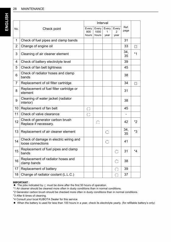
A The jobs indicated by must be done after the first 50 hours of operation.*1 Air cleaner should be cleaned more often in dusty conditions than in normal conditions.*2 Generator carbon brush should be checked more often in dusty conditions than in normal conditions.*3 After 6 times of cleaning.*4 Consult your local KUBOTA Dealer for this service.A When the battery is used for less than 100 hours in a year, check its electrolyte yearly. (for refillable battery’s only)
No. Check point
IntervalRef. page
Every 800
hours
Every 1000 hours
Every 1
year
Every 2
year
1 Check of fuel pipes and clamp bands 31
2 Change of engine oil 33
3 Cleaning of air cleaner element34,35
*1
4 Check of battery electrolyte level 39
5 Check of fan belt tightness 45
6Check of radiator hoses and clamp bands
38
7 Replacement of oil filter cartridge 34
8Replacement of fuel filter cartridge or element
31
9Cleaning of water jacket (radiator interior)
38
10 Replacement of fan belt 45
11 Check of valve clearance -
12Check of generator carbon brush Replace if necessary.
42 *2
13 Replacement of air cleaner element34,35
*3
14Check of damage in electric wiring and loose connections
41
15Replacement of fuel pipes and clamp bands
31 *4
16Replacement of radiator hoses and clamp bands
38
17 Replacement of battery 39
18 Change of radiator coolant (L.L.C.) 37
29PERIODIC SERVICE
NG
LIS
H
PERIODIC SERVICE
E
FUELFuel is flammable and can be dangerous. You shouldhandle fuel with care.
To avoid personal injury:ADO NOT mix gasoline or alcohol with
diesel fuel. This mixture can causean explosion.
ABe careful not to spill fuel duringrefueling. If fuel should spill, wipe itoff at once, or it may cause a fire.
AStop the engine before refueling.Keep the machine away from the fire.
ABe sure to stop the engine whilerefueling or bleeding and whencleaning or changing fuel filter or fuelpipes. DO NOT smoke when workingaround the machine or whenrefueling.
ACheck the above fuel systems in awell ventilated and open place.
AWhen fuel and lubricant are spilled,refuel after the machine cooleddown.
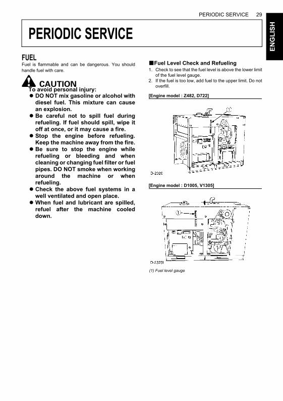
BFuel Level Check and Refueling1. Check to see that the fuel level is above the lower limit
of the fuel level gauge.2. If the fuel is too low, add fuel to the upper limit. Do not
overfill.
[Engine model : Z482, D722]
[Engine model : D1005, V1305]
(1) Fuel level gauge
PERIODIC SERVICE30E
NG
LIS
H
No.2-D is a distillate fuel oil of lower volatility for enginesin industrial and heavy mobile service.(SAE J313 JUN87)Grade of Diesel Fuel Oil According to ASTM D975
The cetane number is required not to be less than 45.
A Be sure to use a strainer when filling the fuel tank, ordirt or sand in the fuel may cause trouble in the fuelinjection pump.
A Always use diesel fuel. You are required not to usealternative fuel, because its quality is unknown andaffect the generator performance. Kerosene, which isvery low in cetane rating, adversely affects the engine.Diesel fuel differs in grades depending on thetemperature.
A Be careful not to let the fuel tank become empty, or aircan enter the fuel system, necessitating bleedingbefore next engine start.
BAir Bleeding the Fuel System
To avoid personal injury;ADo not bleed a hot engine as this
could cause fuel to spill onto a hotexhaust manifold creating a dangerof fire.
Air bleeding of the fuel system is required if;A after the fuel filter and pipes have been detached and
refitted;A after the fuel tank has become empty; orA before the engine is to be used after long storage.
[PROCEDURE]1. Fill the fuel tank to the fullest extent. Open the fuel
filter cock.2. Loosen air vent plug of the fuel filter a few turns.3. Screw back the plug when bubbles do not come up
any more.4. Open the air vent plug on top of the fuel injection
pump.5. Retighten the plug when bubbles do not come up any
more.
Model CapacityJ106, J107
[Engine model : Z482-B]37 (9.8)
J108, J110, J310, J313[Engine model : D722-B]
J112, J114, J315, J318[Engine model : D1005-BG]
J116, J119, J320, J324[Engine model : V1305-BG]
79 (20.9)
L (U.S.gal.)Fuel tank capacity
(1) Fuel filter cock(2) Air vent plug(3) Fuel filter pot
(A) "OPEN"(B) "CLOSE"
31PERIODIC SERVICE
EN
GL
ISH
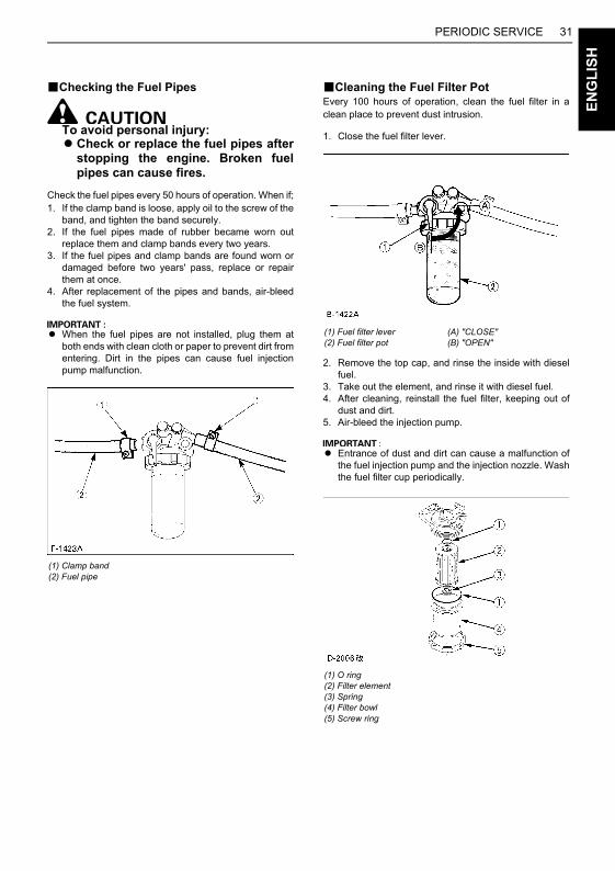
BChecking the Fuel Pipes
To avoid personal injury:ACheck or replace the fuel pipes after
stopping the engine. Broken fuelpipes can cause fires.
Check the fuel pipes every 50 hours of operation. When if;1. If the clamp band is loose, apply oil to the screw of the
band, and tighten the band securely.2. If the fuel pipes made of rubber became worn out
replace them and clamp bands every two years.3. If the fuel pipes and clamp bands are found worn or
damaged before two years' pass, replace or repairthem at once.
4. After replacement of the pipes and bands, air-bleedthe fuel system.
A When the fuel pipes are not installed, plug them atboth ends with clean cloth or paper to prevent dirt fromentering. Dirt in the pipes can cause fuel injectionpump malfunction.
BCleaning the Fuel Filter PotEvery 100 hours of operation, clean the fuel filter in aclean place to prevent dust intrusion.
1. Close the fuel filter lever.
2. Remove the top cap, and rinse the inside with dieselfuel.
3. Take out the element, and rinse it with diesel fuel.4. After cleaning, reinstall the fuel filter, keeping out of
dust and dirt.5. Air-bleed the injection pump.
A Entrance of dust and dirt can cause a malfunction ofthe fuel injection pump and the injection nozzle. Washthe fuel filter cup periodically.
(1) Clamp band(2) Fuel pipe
(1) Fuel filter lever(2) Fuel filter pot
(A) "CLOSE"(B) "OPEN"
(1) O ring(2) Filter element(3) Spring(4) Filter bowl(5) Screw ring
PERIODIC SERVICE32E
NG
LIS
H
ENGINE OIL
To avoid personal injury:ABe sure to stop the engine before
checking and changing the engineoil and the oil filter cartridge.
ADO NOT touch muffler or exhaustpipes while they are hot; severeburns could result. Always stop theengine and allow it to cool beforeconducting inspections,maintenance, or cleaning.
AContact with engine oil can damageyour skin.Put on gloves when handling engineoil. If you come in contact withengine oil, wash it off immediately.
A Be sure to check the engine oil on a level surface. Ifplaced on gradients, oil quantity can not be measuredaccurately.
A Do not operate a diesel engine when engine oil isoverfilled. This can effect the air intake system whichcould result in engine damage or malfunction.
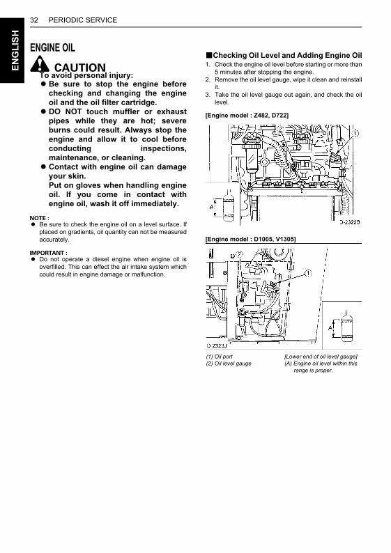
BChecking Oil Level and Adding Engine Oil1. Check the engine oil level before starting or more than
5 minutes after stopping the engine.2. Remove the oil level gauge, wipe it clean and reinstall
it.3. Take the oil level gauge out again, and check the oil
level.
[Engine model : Z482, D722]
[Engine model : D1005, V1305]
(1) Oil port(2) Oil level gauge
[Lower end of oil level gauge](A) Engine oil level within this range is proper.
33PERIODIC SERVICE
EN
GL
ISH
4. If the oil level is too low, remove the oil port, and addnew oil to the prescribed level.
5. After adding oil, wait more than 5 minutes and checkthe oil level again. It takes some time for the oil to draindown to the oil pan.
6. If the engine is operated with the oil level nearing thelower limit, the oil may deteriorate more quickly thannormal, therefore, keeping the oil level near the upperlimit is recommended.
Engine oil capacity L (U.S.qts.)
A Engine oil should be MIL-L-2104C or have propertiesof API classification CF grades or higher.Change the type of engine oil according to theambient temperature.
A When using oil of different brands from the previousone, be sure to drain all the previous oil before addingthe new engine oil.
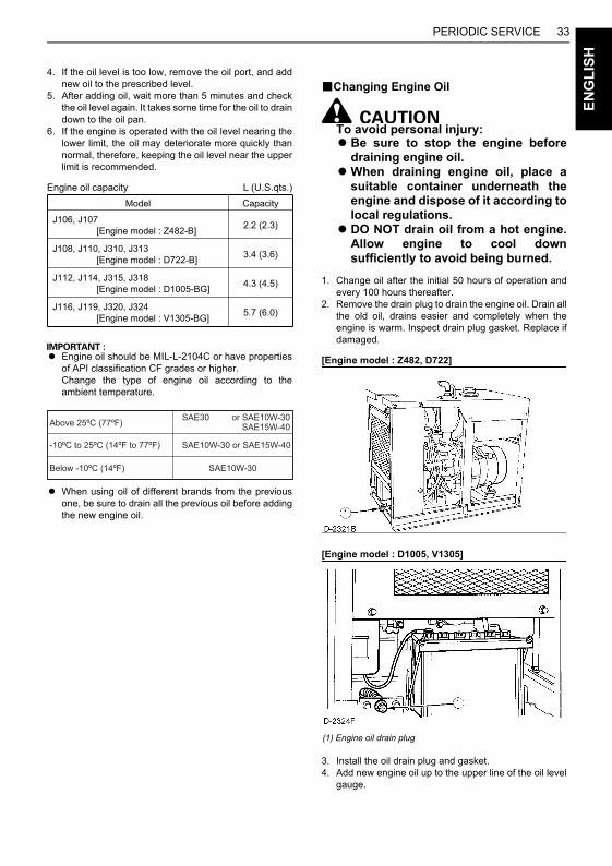
BChanging Engine Oil
To avoid personal injury:ABe sure to stop the engine before
draining engine oil.AWhen draining engine oil, place a
suitable container underneath theengine and dispose of it according tolocal regulations.
ADO NOT drain oil from a hot engine.Allow engine to cool downsufficiently to avoid being burned.
1. Change oil after the initial 50 hours of operation andevery 100 hours thereafter.
2. Remove the drain plug to drain the engine oil. Drain allthe old oil, drains easier and completely when theengine is warm. Inspect drain plug gasket. Replace ifdamaged.
[Engine model : Z482, D722]
[Engine model : D1005, V1305]
3. Install the oil drain plug and gasket.4. Add new engine oil up to the upper line of the oil level
gauge.
Model Capacity
J106, J107 [Engine model : Z482-B] 2.2 (2.3)
J108, J110, J310, J313 [Engine model : D722-B] 3.4 (3.6)
J112, J114, J315, J318 [Engine model : D1005-BG] 4.3 (4.5)
J116, J119, J320, J324 [Engine model : V1305-BG] 5.7 (6.0)
(1) Engine oil drain plug
PERIODIC SERVICE34E
NG
LIS
H
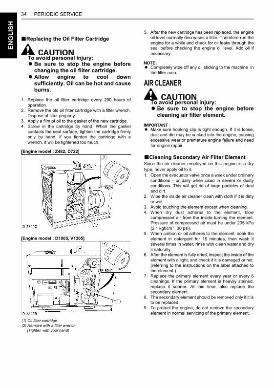
BReplacing the Oil Filter Cartridge
To avoid personal injury:ABe sure to stop the engine before
changing the oil filter cartridge.AAllow engine to cool down
sufficiently. Oil can be hot and causeburns.
1. Replace the oil filter cartridge every 200 hours ofoperation.
2. Remove the old oil filter cartridge with a filter wrench.Dispose of filter properly.
3. Apply a film of oil to the gasket of the new cartridge.4. Screw in the cartridge by hand. When the gasket
contacts the seal surface, tighten the cartridge firmlyonly by hand. If you tighten the cartridge with awrench, it will be tightened too much.
[Engine model : Z482, D722]
[Engine model : D1005, V1305]
5. After the new cartridge has been replaced, the engineoil level normally decreases a little. Therefore run theengine for a while and check for oil leaks through theseal before checking the engine oil level. Add oil ifnecessary.
A Completely wipe off any oil sticking to the machine inthe filter area.
AIR CLEANER
To avoid personal injury:ABe sure to stop the engine before
cleaning air filter element.
A Make sure hooking clip is tight enough. If it is loose,dust and dirt may be sucked into the engine, causingexcessive wear or premature engine failure and needfor engine repair.
BCleaning Secondary Air Filter ElementSince the air cleaner employed on this engine is a drytype, never apply oil to it.1. Open the evacuator valve once a week under ordinary
conditions - or daily when used in severe or dustyconditions. This will get rid of large particles of dustand dirt.
2. Wipe the inside air cleaner clean with cloth if it is dirtyor wet.
3. Avoid touching the element except when cleaning.4. When dry dust adheres to the element, blow
compressed air from the inside turning the element.Pressure of compressed air must be under 205 kPa(2.1 kgf/cm , 30 psi).
5. When carbon or oil adheres to the element, soak theelement in detergent for 15 minutes, then wash itseveral times in water, rinse with clean water and dryit naturally.
6. After the element is fully dried, inspect the inside of theelement with a light, and check if it is damaged or not.(referring to the instructions on the label attached tothe element.)
7. Replace the primary element every year or every 6cleanings. If the primary element is heavily stained,replace it sooner. At this time, also replace thesecondary element.
8. The secondary element should be removed only if it isto be replaced.
9. To protect the engine, do not remove the secondaryelement in normal servicing of the primary element.
(1) Oil filter cartridge(2) Remove with a filter wrench (Tighten with your hand)

35PERIODIC SERVICE
EN
GL
ISH
[Engine model : Z482, D722]
[Engine model : D1005, V1305]
BCleaning Primary Air Filter Element1. To clean the element, use clean dry compressed air
on the inside of the element.Air pressure at the nozzle must not exceed 205 kPa(2.1 kgf/cm , 30 psi).Maintain reasonable distance between the nozzle andfilter.
2. To wash the elements, use Donaldson ND-1500 FilterCleaner, or its equivalent, which is especially effectiveon oily and soot-laden filters. Follow instructions thatare supplied with the filter cleaner.
BEvacuator ValveOpen the evacuator valve once a week under ordinaryconditions - or daily when used in dusty condition - to getrid of large particles of dust and dirt.
A If the dust cup is mounted incorrectly, dust or dirt willnot collect in the cup and allow the dust to come intodirect contact with the element and thus require theelement be replaced prematurely.
BFor the Air Cleaner with a Dust CupRemove and clean out the dust cup once a week undernormal conditions or daily in extreme conditions.Do not allow the dust cup to fill above half way regardlessof conditions.Install the air cleaner dust cup with "TOP" indicated on therear of the cup in the upward position with horizontallymounted air cleaner bodies or vertically mounted aircleaner bodies, the cup may be mounted in any direction.
(1) Air cleaner body(2) Cover(3) Secondary element(4) Primary element(5) Evacuator valve(6) Hooking clip(7) Air cleaner
(1) Air cleaner body(2) Secondary element(3) Primary element(4) Dust cup(5) "TOP" mark(6) Evacuator valve
PERIODIC SERVICE36E
NG
LIS
H
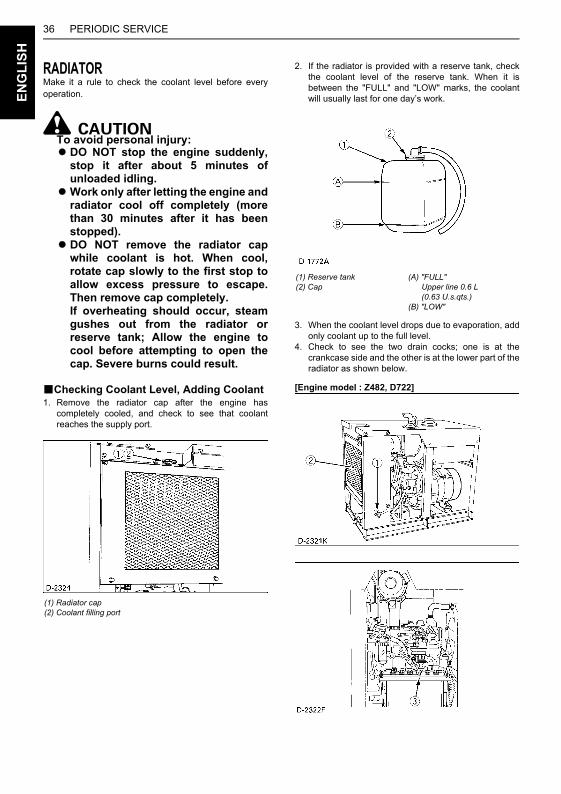
RADIATORMake it a rule to check the coolant level before everyoperation.
To avoid personal injury:ADO NOT stop the engine suddenly,
stop it after about 5 minutes ofunloaded idling.
AWork only after letting the engine andradiator cool off completely (morethan 30 minutes after it has beenstopped).
ADO NOT remove the radiator capwhile coolant is hot. When cool,rotate cap slowly to the first stop toallow excess pressure to escape.Then remove cap completely.If overheating should occur, steamgushes out from the radiator orreserve tank; Allow the engine tocool before attempting to open thecap. Severe burns could result.
BChecking Coolant Level, Adding Coolant1. Remove the radiator cap after the engine has
completely cooled, and check to see that coolantreaches the supply port.
2. If the radiator is provided with a reserve tank, checkthe coolant level of the reserve tank. When it isbetween the "FULL" and "LOW" marks, the coolantwill usually last for one day’s work.
3. When the coolant level drops due to evaporation, addonly coolant up to the full level.
4. Check to see the two drain cocks; one is at thecrankcase side and the other is at the lower part of theradiator as shown below.
[Engine model : Z482, D722]
(1) Radiator cap(2) Coolant filling port
(1) Reserve tank(2) Cap
(A) "FULL" Upper line 0.6 L (0.63 U.s.qts.)(B) "LOW"
37PERIODIC SERVICE
EN
GL
ISH
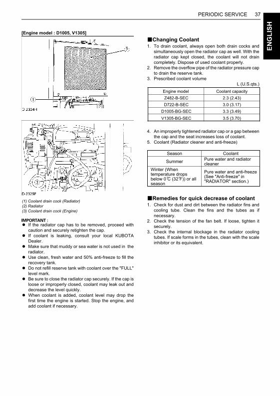
[Engine model : D1005, V1305]
A If the radiator cap has to be removed, proceed withcaution and securely retighten the cap.
A If coolant is leaking, consult your local KUBOTADealer.
A Make sure that muddy or sea water is not used in theradiator.
A Use clean, fresh water and 50% anti-freeze to fill therecovery tank.
A Do not refill reserve tank with coolant over the "FULL"level mark.
A Be sure to close the radiator cap securely. If the cap isloose or improperly closed, coolant may leak out anddecrease the level quickly.
A When coolant is added, coolant level may drop thefirst time the engine is started. Stop the engine, andadd coolant if necessary.
BChanging Coolant1. To drain coolant, always open both drain cocks and
simultaneously open the radiator cap as well. With theradiator cap kept closed, the coolant will not draincompletely. Dispose of used coolant properly.
2. Remove the overflow pipe of the radiator pressure capto drain the reserve tank.
3. Prescribed coolant volume L (U.S.qts.)
4. An improperly tightened radiator cap or a gap betweenthe cap and the seat increases loss of coolant.
5. Coolant (Radiator cleaner and anti-freeze)
BRemedies for quick decrease of coolant1. Check for dust and dirt between the radiator fins and
cooling tube. Clean the fins and the tubes as ifnecessary.
2. Check the tension of the fan belt. If loose, tighten itsecurely.
3. Check the internal blockage in the radiator coolingtubes. If scale forms in the tubes, clean with the scaleinhibitor or its equivalent.
(1) Coolant drain cock (Radiator) (2) Radiator(3) Coolant drain cock (Engine)
Engine model Coolant capacityZ482-B-SEC 2.3 (2.43)D722-B-SEC 3.0 (3.17)
D1005-BG-SEC 3.3 (3.49)V1305-BG-SEC 3.5 (3.70)
Season
Summer
Winter (Whentemperature dropsbelow 0 C (32 F)) or allseason
CoolantPure water and radiatorcleaner
Pure water and anti-freeze(See "Anti-freeze" in"RADIATOR" section.)
PERIODIC SERVICE38E
NG
LIS
H
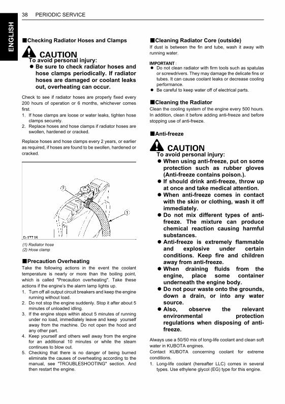
BChecking Radiator Hoses and Clamps
To avoid personal injury:ABe sure to check radiator hoses and
hose clamps periodically. If radiatorhoses are damaged or coolant leaksout, overheating can occur.
Check to see if radiator hoses are properly fixed every200 hours of operation or 6 months, whichever comesfirst.1. If hose clamps are loose or water leaks, tighten hose
clamps securely.2. Replace hoses and hose clamps if radiator hoses are
swollen, hardened or cracked.
Replace hoses and hose clamps every 2 years, or earlieras required, if hoses are found to be swollen, hardened orcracked.
BPrecaution OverheatingTake the following actions in the event the coolanttemperature is nearly or more than the boiling point,which is called "Precaution overheating". Take theseactions if the engine’s the alarm lamp lights up.1. Turn off all output circuit breakers and keep the engine
running without load.2. Do not stop the engine suddenly. Stop it after about 5
minutes of unloaded idling.3. If the engine stops within about 5 minutes of running
under no load, immediately leave and keep yourselfaway from the machine. Do not open the hood andany other part.
4. Keep yourself and others well away from the enginefor an additional 10 minutes or while the steamcontinues to blow out.
5. Checking that there is no danger of being burnedeliminate the causes of overheating according to themanual, see "TROUBLESHOOTING" section. Andthen restart the engine.
BCleaning Radiator Core (outside)If dust is between the fin and tube, wash it away withrunning water.
A Do not clean radiator with firm tools such as spatulasor screwdrivers. They may damage the delicate fins ortubes. It can cause coolant leaks or decrease coolingperformance.
A Be careful to keep water off of electrical parts.
BCleaning the RadiatorClean the cooling system of the engine every 500 hours.In addition, clean it before adding anti-freeze and beforestopping use of anti-freeze.
BAnti-freeze
To avoid personal injury:AWhen using anti-freeze, put on some
protection such as rubber gloves(Anti-freeze contains poison.).
A If should drink anti-freeze, throw upat once and take medical attention.
AWhen anti-freeze comes in contactwith the skin or clothing, wash it offimmediately.
ADo not mix different types of anti-freeze. The mixture can producechemical reaction causing harmfulsubstances.
AAnti-freeze is extremely flammableand explosive under certainconditions. Keep fire and childrenaway from anti-freeze.
AWhen draining fluids from theengine, place some containerunderneath the engine body.
ADo not pour waste onto the grounds,down a drain, or into any watersource.
AAlso, observe the relevantenvironmental protectionregulations when disposing of anti-freeze.
Always use a 50/50 mix of long-life coolant and clean softwater in KUBOTA engines.Contact KUBOTA concerning coolant for extremeconditions. 1. Long-life coolant (hereafter LLC) comes in several
types. Use ethylene glycol (EG) type for this engine.
(1) Radiator hose(2) Hose clamp
39PERIODIC SERVICE
EN
GL
ISH
2. Before employing LLC-mixed cooling water, flush theradiator with fresh water. Repeat this procedure 2 or 3times to clean up the radiator and engine block frominside.
3. Mixing the LLCPremix 50% LLC with 50% clean soft water. Whenmixing, stir it up well, and then fill into the radiator.
4. The procedure for the mixing of water and anti-freezediffers according to the make of the anti-freeze. Referto SAE J1034 standard, more specifically also to SAEJ814c.
* At 1.013 x 10 Pa (760 mmHg) pressure (atmospheric).A higher boiling point is obtained by using a radiatorpressure cap which permits the development ofpressure within the cooling system.
5. Adding the LLC(1) Add only water if the coolant level reduces in the
cooling system by evaporation.(2) If there is a coolant leak, add the LLC of the same
manufacturer and type in the same coolantpercentage.
*Never add any long-life coolant of differentmanufacturer. (Different brands may have differentadditive components, and the engine may fail toperform as specified.)
6. When the LLC is mixed, do not employ any radiatorcleaning agent. The LLC contains anticorrosive agent.If mixed with the cleaning agent, sludge may build up,adversely affecting the engine parts.
7. Kubota's genuine long-life coolant has a service life of2 years. Be sure to change the coolant every 2 years.
A The above data represent industry standards thatnecessitate minimum glycol content in theconcentrated anti-freeze.
BATTERY
To avoid personal injury:ABe careful not to let the battery
electrolyte contact your body orclothing.
AWear eye protection and rubbergloves, since the diluted sulfuric acidsolution burns skin and eyes, andeats holes in clothing. Should thisoccur, immediately wash it off withrunning water and get medicalattention.
Mishandling of the battery shortens the service life andadds to maintenance costs. Obtain the maximumperformance and the longest life of the battery byhandling properly and with care.Engine starting will be difficult, if the battery charge is low.Be sure to keep the battery in a fully charged state for bestperformance and battery life.
BBattery Charging
To avoid the possibility of batteryexplosion:The batteries come in two types:refillable and non-refillable. For usingthe refillable type battery, follow theinstructions below.ADO NOT use or charge the battery if
the fluid level is below the LOWER(lower limit level) mark.Otherwise, the battery componentparts may deteriorate prematurely,which will shorten the battery’sservice life or may cause anexplosion.Immediately, add distilled water untilthe battery’s fluid level comessomewhere between the UPPER andLOWER levels.
AWhen the battery is being activated,hydrogen and oxygen gases in thebattery are extremely explosive.Keep open sparks and flames awayfrom the battery at all times,especially when charging thebattery.
AWhen charging the battery, ensurethe vent caps are securely in place (ifequipped).
AWhen disconnecting the cable fromthe battery, start with the negativeterminal, and when connecting them,start with the positive terminal first.
ADO NOT check the battery charge byplacing a metal object across theterminals. Use a voltmeter orhydrometer.
Vol %Anti-freeze
Freezing Point Boiling Point*
C F C F
50 -37 -34 108 226
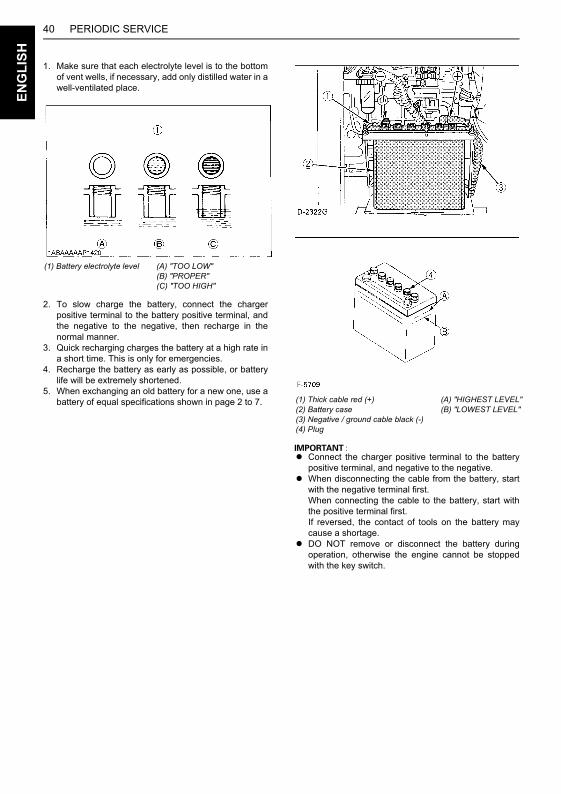
PERIODIC SERVICE40E
NG
LIS
H
1. Make sure that each electrolyte level is to the bottomof vent wells, if necessary, add only distilled water in awell-ventilated place.
2. To slow charge the battery, connect the chargerpositive terminal to the battery positive terminal, andthe negative to the negative, then recharge in thenormal manner.
3. Quick recharging charges the battery at a high rate ina short time. This is only for emergencies.
4. Recharge the battery as early as possible, or batterylife will be extremely shortened.
5. When exchanging an old battery for a new one, use abattery of equal specifications shown in page 2 to 7.
A Connect the charger positive terminal to the batterypositive terminal, and negative to the negative.
A When disconnecting the cable from the battery, startwith the negative terminal first.When connecting the cable to the battery, start withthe positive terminal first.If reversed, the contact of tools on the battery maycause a shortage.
A DO NOT remove or disconnect the battery duringoperation, otherwise the engine cannot be stoppedwith the key switch.
(1) Battery electrolyte level (A) "TOO LOW"(B) "PROPER"(C) "TOO HIGH"
(1) Thick cable red (+)(2) Battery case(3) Negative / ground cable black (-)(4) Plug
(A) "HIGHEST LEVEL"(B) "LOWEST LEVEL"
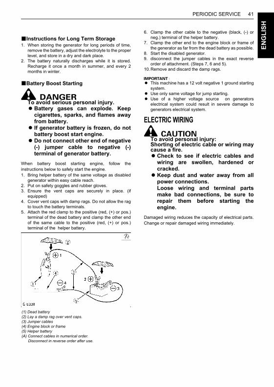
41PERIODIC SERVICE
EN
GL
ISH
BInstructions for Long Term Storage1. When storing the generator for long periods of time,
remove the battery, adjust the electrolyte to the properlevel, and store in a dry and dark place.
2. The battery naturally discharges while it is stored.Recharge it once a month in summer, and every 2months in winter.
BBattery Boost Starting
To avoid serious personal injury.ABattery gases can explode. Keep
cigarettes, sparks, and flames awayfrom battery.
A If generator battery is frozen, do notbattery boost start engine.
ADo not connect other end of negative(-) jumper cable to negative (-)terminal of generator battery.
When battery boost starting engine, follow theinstructions below to safely start the engine.1. Bring helper battery of the same voltage as disabled
generator within easy cable reach.2. Put on safety goggles and rubber gloves.3. Ensure the vent caps are securely in place. (if
equipped)4. Cover vent caps with damp rags. Do not allow the rag
to touch the battery terminals.5. Attach the red clamp to the positive (red, (+) or pos.)
terminal of the dead battery and clamp the other endof the same cable to the positive (red, (+) or pos.)terminal of the helper battery.
6. Clamp the other cable to the negative (black, (-) orneg.) terminal of the helper battery.
7. Clamp the other end to the engine block or frame ofthe generator as far from the dead battery as possible.
8. Start the disabled generator.9. disconnect the jumper cables in the exact reverse
order of attachment. (Steps 7, 6 and 5).10.Remove and discard the damp rags.
A This machine has a 12 volt negative 1 ground startingsystem.
A Use only same voltage for jump starting.A Use of a higher voltage source on generators
electrical system could result in severe damage togenerators electrical system.
ELECTRIC WIRING
To avoid personal injury:Shorting of electric cable or wiring maycause a fire.ACheck to see if electric cables and
wiring are swollen, hardened orcracked.
AKeep dust and water away from allpower connections.Loose wiring and terminal partsmake bad connections, be sure torepair them before starting theengine.
Damaged wiring reduces the capacity of electrical parts.Change or repair damaged wiring immediately.
(1) Dead battery(2) Lay a damp rag over vent caps.(3) Jumper cables(4) Engine block or frame(5) Helper battery(A) Connect cables in numerical order. Disconnect in reverse order after use.
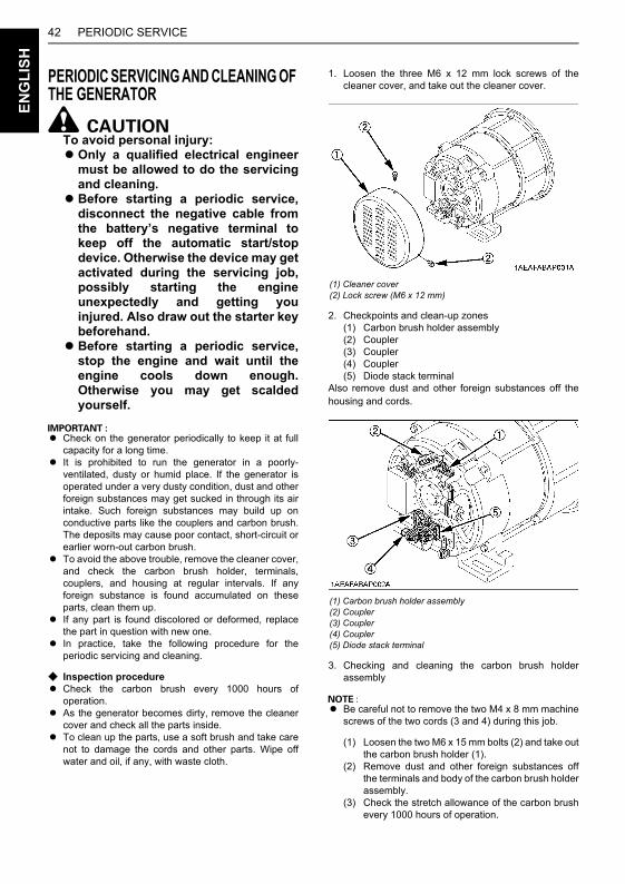
PERIODIC SERVICE42E
NG
LIS
H
PERIODIC SERVICING AND CLEANING OF THE GENERATOR
To avoid personal injury:AOnly a qualified electrical engineer
must be allowed to do the servicingand cleaning.
ABefore starting a periodic service,disconnect the negative cable fromthe battery’s negative terminal tokeep off the automatic start/stopdevice. Otherwise the device may getactivated during the servicing job,possibly starting the engineunexpectedly and getting youinjured. Also draw out the starter keybeforehand.
ABefore starting a periodic service,stop the engine and wait until theengine cools down enough.Otherwise you may get scaldedyourself.
A Check on the generator periodically to keep it at fullcapacity for a long time.
A It is prohibited to run the generator in a poorly-ventilated, dusty or humid place. If the generator isoperated under a very dusty condition, dust and otherforeign substances may get sucked in through its airintake. Such foreign substances may build up onconductive parts like the couplers and carbon brush.The deposits may cause poor contact, short-circuit orearlier worn-out carbon brush.
A To avoid the above trouble, remove the cleaner cover,and check the carbon brush holder, terminals,couplers, and housing at regular intervals. If anyforeign substance is found accumulated on theseparts, clean them up.
A If any part is found discolored or deformed, replacethe part in question with new one.
A In practice, take the following procedure for theperiodic servicing and cleaning.
C Inspection procedureA Check the carbon brush every 1000 hours of
operation.A As the generator becomes dirty, remove the cleaner
cover and check all the parts inside.A To clean up the parts, use a soft brush and take care
not to damage the cords and other parts. Wipe offwater and oil, if any, with waste cloth.
1. Loosen the three M6 x 12 mm lock screws of thecleaner cover, and take out the cleaner cover.
2. Checkpoints and clean-up zones(1) Carbon brush holder assembly(2) Coupler(3) Coupler(4) Coupler(5) Diode stack terminal
Also remove dust and other foreign substances off thehousing and cords.
3. Checking and cleaning the carbon brush holderassembly
A Be careful not to remove the two M4 x 8 mm machinescrews of the two cords (3 and 4) during this job.
(1) Loosen the two M6 x 15 mm bolts (2) and take outthe carbon brush holder (1).
(2) Remove dust and other foreign substances offthe terminals and body of the carbon brush holderassembly.
(3) Check the stretch allowance of the carbon brushevery 1000 hours of operation.
(1) Cleaner cover(2) Lock screw (M6 x 12 mm)
(1) Carbon brush holder assembly(2) Coupler(3) Coupler(4) Coupler(5) Diode stack terminal
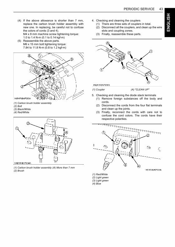
43PERIODIC SERVICE
EN
GL
ISH
(4) If the above allowance is shorter than 7 mm,replace the carbon brush holder assembly withnew one. In replacing, be careful not to confusethe colors of cords (3 and 4).M4 x 8 mm machine screw tightening torque: 1.0 to 1.4 N-m (0.1 to 0.14 kgf-m)
(5) Reassemble the above parts.M6 x 15 mm bolt tightening torque: 7.84 to 11.8 N-m (0.8 to 1.2 kgf-m)
4. Checking and cleaning the couplers(1) There are three sets of couplers in total.(2) Disconnect all the couplers, and clean up the wire
slots and coupling zones.(3) Finally, reassemble these parts.
5. Checking and cleaning the diode stack terminals(1) Remove foreign substances off the body and
cords.(2) Disconnect the cords from the four flat terminals
and clean up the joints.(3) Finally, reconnect the cords with care not to
confuse the cord colors. The cords have theirrespective polarities.
(1) Carbon brush holder assembly(2) Bolt(3) Black/White(4) Red/White
(1) Carbon brush holder assembly(2) Brush
(A) More than 7 mm
(1) Coupler (A) "CLEAN UP"
(1) Red/White(2) Light green(3) Light green(4) Blue
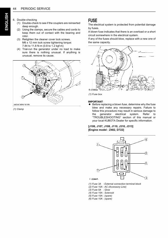
PERIODIC SERVICE44E
NG
LIS
H
6. Double-checking(1) Double-check to see if the couplers are reinserted
deep enough.(2) Using the clamps, secure the cables and cords to
keep them out of contact with the bearing androtor.
(3) Retighten the cleaner cover lock screws.M6 x 12 mm lock screw tightening torque: 7.84 to 11.8 N-m (0.8 to 1.2 kgf-m)
(4) Trial-run the generator under no load to makesure there is nothing unusual. If anything isunusual, remove its cause.
FUSEThe electrical system is protected from potential damageby fuses.A blown fuse indicates that there is an overload or a shortcircuit somewhere in the electrical system.If any of the fuses should blow, replace with a new one ofthe same capacity.
A Before replacing a blown fuse, determine why the fuseblew and make any necessary repairs. Failure tofollow this procedure may result in serious damage tothe generator electrical system. Refer to“TROUBLESHOOTING“ section of this manual oryour local KUBOTA Dealer for specific information.
[J106, J107, J108, J110, J310, J313] [Engine model : Z482, D722]
(1) Clamp
(1) Fuse box
(1) Fuse 3A(2) Fuse 10A(3) Fuse 5A(4) Fuse 15A(5) Fuse 15A(6) Fuse 10A
: External connection terminal block: AC (Accessory Line): Glow: Solenoid: (spare): (spare)
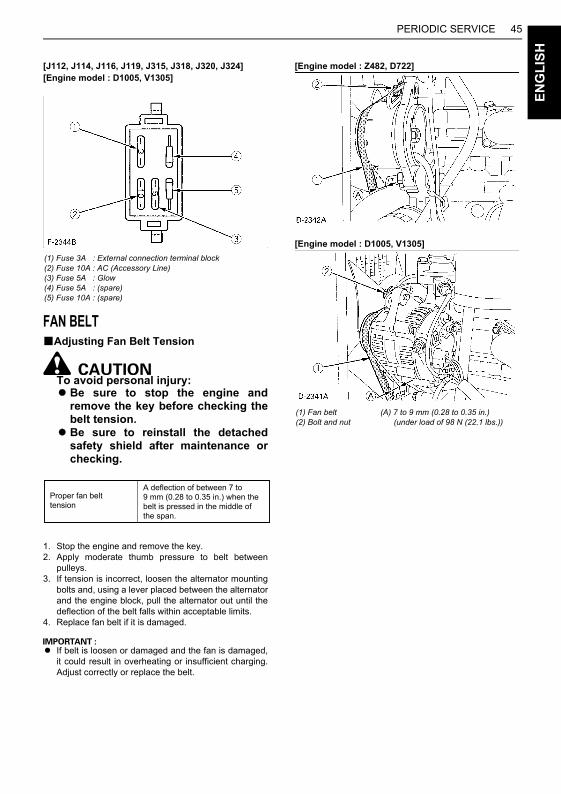
45PERIODIC SERVICE
EN
GL
ISH
[J112, J114, J116, J119, J315, J318, J320, J324] [Engine model : D1005, V1305]
FAN BELTBAdjusting Fan Belt Tension
To avoid personal injury:ABe sure to stop the engine and
remove the key before checking thebelt tension.
ABe sure to reinstall the detachedsafety shield after maintenance orchecking.
1. Stop the engine and remove the key.2. Apply moderate thumb pressure to belt between
pulleys.3. If tension is incorrect, loosen the alternator mounting
bolts and, using a lever placed between the alternatorand the engine block, pull the alternator out until thedeflection of the belt falls within acceptable limits.
4. Replace fan belt if it is damaged.
A If belt is loosen or damaged and the fan is damaged,it could result in overheating or insufficient charging.Adjust correctly or replace the belt.
[Engine model : Z482, D722]
[Engine model : D1005, V1305]
(1) Fuse 3A(2) Fuse 10A(3) Fuse 5A(4) Fuse 5A(5) Fuse 10A
: External connection terminal block: AC (Accessory Line): Glow: (spare): (spare)
Proper fan belttension
A deflection of between 7 to 9 mm (0.28 to 0.35 in.) when the belt is pressed in the middle of the span.
(1) Fan belt(2) Bolt and nut
(A) 7 to 9 mm (0.28 to 0.35 in.) (under load of 98 N (22.1 lbs.))

46 TRANSPORTING / STORAGEE
NG
LIS
H
TRANSPORTING / STORAGE
MOKUJIYOUBTransporting
To avoid personal injury:ASecure the generator to prevent
movement during operation.ADO NOT stand near or under the
generator while it is suspended.AThe generator is heavy. Utilize
suitable equipment to lift andtransport. Keep hands and feet awayfrom under the suspendedgenerator.
AWhen transporting the generator,remove the (-) battery cable, closethe fuel cock lever, and keep thegenerator level to prevent fuelspillage.
AUse hangers and wire ropes whichare strong enough to withstand theweight of the machine.
1. When transporting the generator, use only suitabletransporting equipment, such as crane, fork lift or etc.
2. The generator is equipped with the 2 inlets in themachine bed for forklift forks. Transportability isincreased by 2 ways; special forklift openings and 1-point lifting hook.Use lifting equipment of sufficient capacity.
BStorage
To avoid personal injury:ADO NOT clean the machine with
engine running.ATo avoid the danger of exhaust fume
poisoning, do not operate the enginein a closed building without properventilation.
AWhen storing the generator just afterrunning, let the engine cool off.
Before storing the generator for more than a few months,remove any dirt on the machine, and:1. Remove dirty engine coolant, fill with new coolant and
run the engine for about 5 minutes.When coolant is added, coolant level drops the firsttime the engine is started, stop the engine and addmore coolant.
2. Remove dirty engine oil, fill with new oil and run theengine for about 5 minutes to let the oil penetrate to allthe parts.
3. Check all the bolts and nuts, and tighten if necessary.4. Remove the battery from the generator, adjust the
electrolyte level, and recharge it. Store the battery in adry and dark place.
5. When the engine is not used for a long period of time,run it for about 5 minutes under no load every 2 to 3months to keep it free from rust. If the engine is storedwithout any running, moisture in the air may condenseinto dew over the sliding parts of the engine, resultingin rust.
6. If you forget to run the engine for longer than 5 to 6months, apply enough engine oil to the valve guideand valve stem seal and make sure the valves worksmoothly before starting the engine.
7. Store the generator in a flat place and remove the key.8. Do not store the generator in a place where flammable
materials such as dry grass or straw are present.9. When covering the generator for storage, let engine
and muffler cool off completely. 10.Operate the engine after checking and repairing
damaged wiring or pipes, and clearing flammablematerials carried by rodents, insects or birds.
Model Approx. gross wt. kg (lbs.)J106, J107
[Engine model: Z482-B] 260 (573)
J108, J110, J310, J313[Engine model: D722-B]
J112, J114, J315, J318[Engine model: D1005-BG]
J116, J119, J320, J324[Engine model: V1305-BG]
290 (639)
410 (904)
455 (1003)
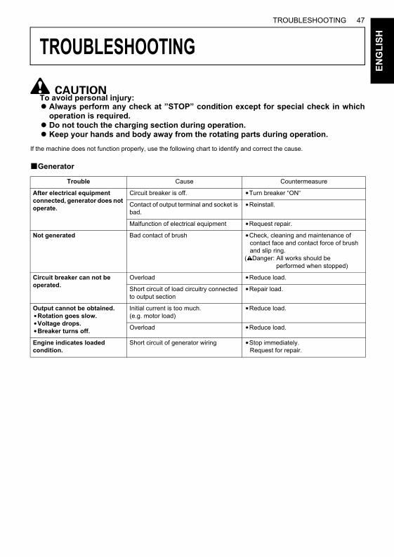
47TROUBLESHOOTING
NG
LIS
H
TROUBLESHOOTING
E
MOKUJIYOU
To avoid personal injury:AAlways perform any check at ”STOP” condition except for special check in which
operation is required. ADo not touch the charging section during operation.AKeep your hands and body away from the rotating parts during operation.
If the machine does not function properly, use the following chart to identify and correct the cause.
BGenerator
Trouble Cause Countermeasure
After electrical equipment connected, generator does not operate.
Circuit breaker is off. Turn breaker “ON“
Contact of output terminal and socket is bad.
Reinstall.
Malfunction of electrical equipment Request repair.
Not generated Bad contact of brush Check, cleaning and maintenance of contact face and contact force of brush and slip ring.( Danger: All works should be performed when stopped)
Circuit breaker can not be operated.
Overload Reduce load.
Short circuit of load circuitry connected to output section
Repair load.
Output cannot be obtained.Rotation goes slow.Voltage drops.Breaker turns off.
Initial current is too much.(e.g. motor load)
Reduce load.
Overload Reduce load.
Engine indicates loaded condition.
Short circuit of generator wiring Stop immediately. Request for repair.
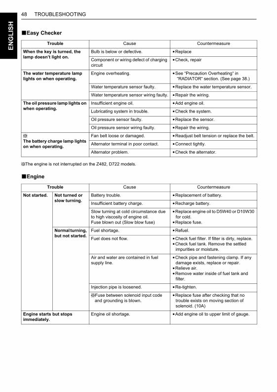
48 TROUBLESHOOTINGE
NG
LIS
H
BEasy Checker
The engine is not interrupted on the Z482, D722 models.
BEngine
Trouble Cause Countermeasure
When the key is turned, the lamp doesn’t light on.
Bulb is below or defective. Replace
Component or wiring defect of charging circuit
Check, repair
The water temperature lamp lights on when operating.
Engine overheating. See “Precaution Overheating“ in “RADIATOR“ section. (See page 38.)
Water temperature sensor faulty. Replace the water temperature sensor.
Water temperature sensor wiring faulty. Repair the wiring.
The oil pressure lamp lights on when operating.
Insufficient engine oil. Add engine oil.
Lubricating system in trouble. Check the system.
Oil pressure sensor faulty. Replace the sensor.
Oil pressure sensor wiring faulty. Repair the wiring.
The battery charge lamp lights on when operating.
Fan belt loose or damaged. Readjust belt tension or replace the belt.
Alternator terminal in poor contact. Connect tightly.
Alternator problem. Check the alternator.
Trouble Cause Countermeasure
Not started. Not turned or slow turning.
Battery trouble. Replacement of battery.
Insufficient battery charge. Recharge battery.
Slow turning at cold circumstance due to high viscosity of engine oil.Fuse blown out (Slow blow fuse)
Replace engine oil to D5W40 or D10W30 for cold.
Replace fuse.
Normal turning, but not started.
Fuel shortage. Refuel.
Fuel does not flow. Check fuel filter. If filter is dirty, replace.Check fuel tank. Remove the settled
impurities or moisture.
Air and water are contained in fuel supply line.
Check pipe and fastening clamp. If any damage exists, replace or repair.
Relieve air.Remove water inside of fuel tank and
filter.
Injection pipe is loosened. Re-tighten.
Fuse between solenoid input code and grounding is blown.
Replace fuse after checking that no trouble exists on moving section of solenoid. (10A)
Engine starts but stops immediately.
Engine oil shortage. Add engine oil to upper limit of gauge.
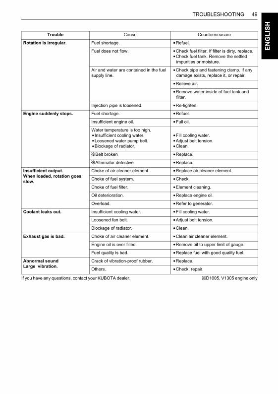
49TROUBLESHOOTING
EN
GL
ISH
If you have any questions, contact your KUBOTA dealer. D1005, V1305 engine only
Rotation is irregular. Fuel shortage. Refuel.
Fuel does not flow. Check fuel filter. If filter is dirty, replace.Check fuel tank. Remove the settled
impurities or moisture.
Air and water are contained in the fuel supply line.
Check pipe and fastening clamp. If any damage exists, replace it, or repair.
Relieve air.
Remove water inside of fuel tank and filter.
Injection pipe is loosened. Re-tighten.
Engine suddenly stops. Fuel shortage. Refuel.
Insufficient engine oil. Full oil.
Water temperature is too high.Insufficient cooling water.Loosened water pump belt.Blockage of radiator.
Fill cooling water.Adjust belt tension.Clean.
Belt broken Replace.
Alternator defective Replace.
Insufficient output.When loaded, rotation goes slow.
Choke of air cleaner element. Replace air cleaner element.
Choke of fuel system. Check.
Choke of fuel filter. Element cleaning.
Oil deterioration. Replace engine oil.
Overload. Refer to generator.
Coolant leaks out. Insufficient cooling water. Fill cooling water.
Loosened fan belt. Adjust belt tension.
Blockage of radiator. Clean.
Exhaust gas is bad. Choke of air cleaner element. Clean air cleaner element.
Engine oil is over filled. Remove oil to upper limit of gauge.
Fuel quality is bad. Replace fuel with good quality fuel.
Abnormal sound Large vibration.
Crack of vibration-proof rubber. Replace.
Others. Check, repair.
Trouble Cause Countermeasure
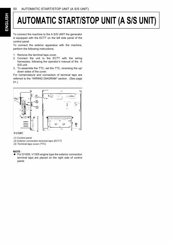
50 AUTOMATIC START/STOP UNIT (A S/S UNIT)E
NG
LIS
H
AUTOMATIC START/STOP UNIT (A S/S UNIT)
To connect the machine to the A S/S UNIT the generatoris equipped with the ECTT on the left side panel of thecontrol panel.To connect the exterior apparatus with the machine,perform the following instructions;1. Remove the terminal taps cover.2. Connect the unit to the ECTT with the wiring
harnesses, following the operator’s manual of the AS/S unit.
3. To assemble the TTC, set the TTC, reversing the up/down sides of the cover.
For nomenclature and connection of terminal taps arereferred to the “WIRING DIAGRAM” section . (See page51.)
A For D1005, V1305 engine type the exterior connectionterminal taps are placed on the right side of controlpanel.
(1) Control panel(2) Exterior connection terminal taps (ECTT)(3) Terminal taps cover (TTC)
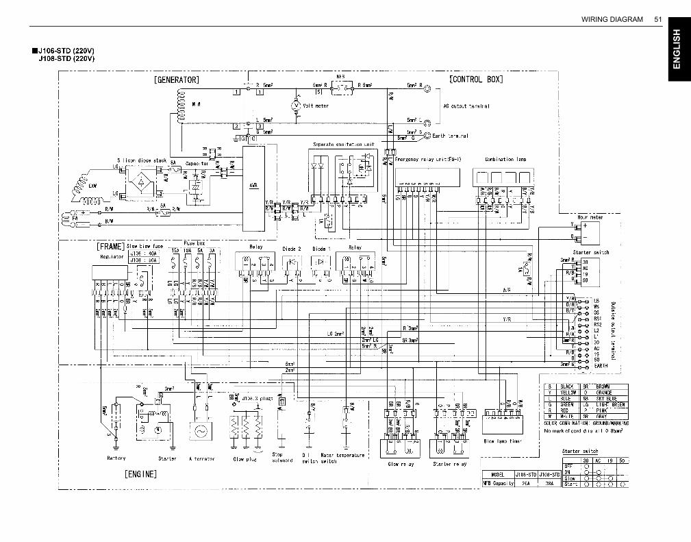
WIRING DIAGRAM 51
EN
GL
ISH
WIRING DIAGRAM
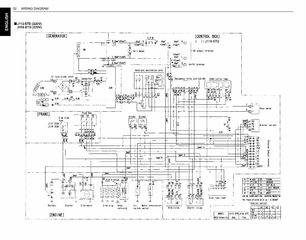
WIRING DIAGRAM52E
NG
LIS
H
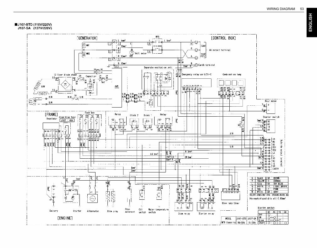
WIRING DIAGRAM 53
EN
GL
ISH
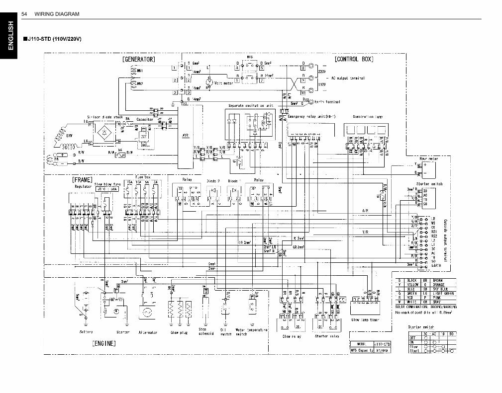
WIRING DIAGRAM54E
NG
LIS
H
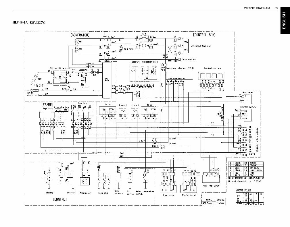
WIRING DIAGRAM 55
EN
GL
ISH
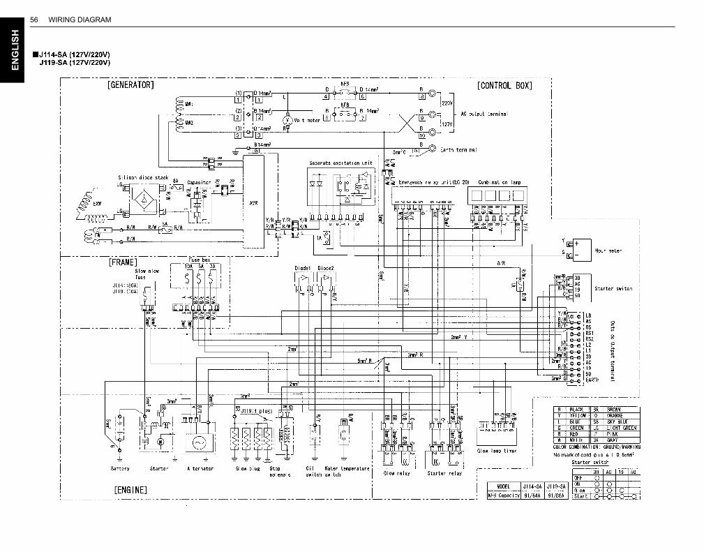
WIRING DIAGRAM56E
NG
LIS
H
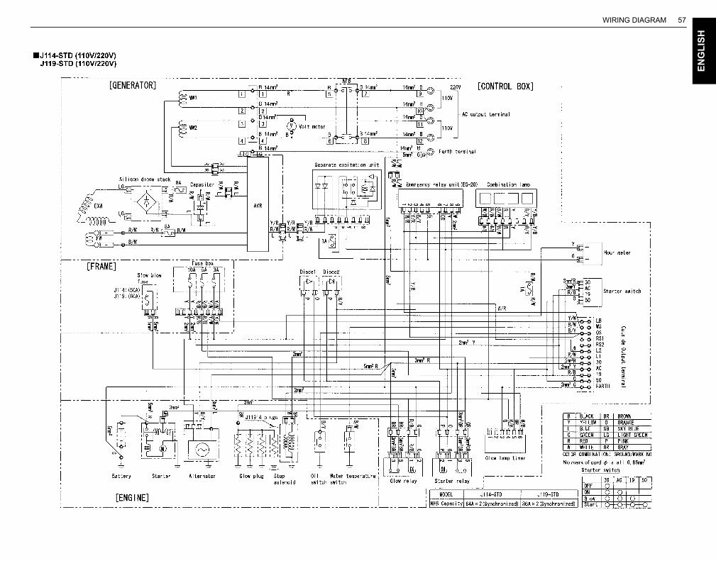
WIRING DIAGRAM 57
EN
GL
ISH
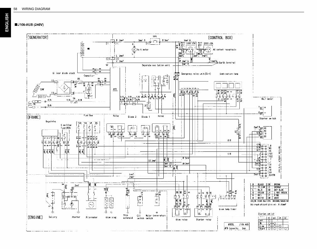
WIRING DIAGRAM58E
NG
LIS
H
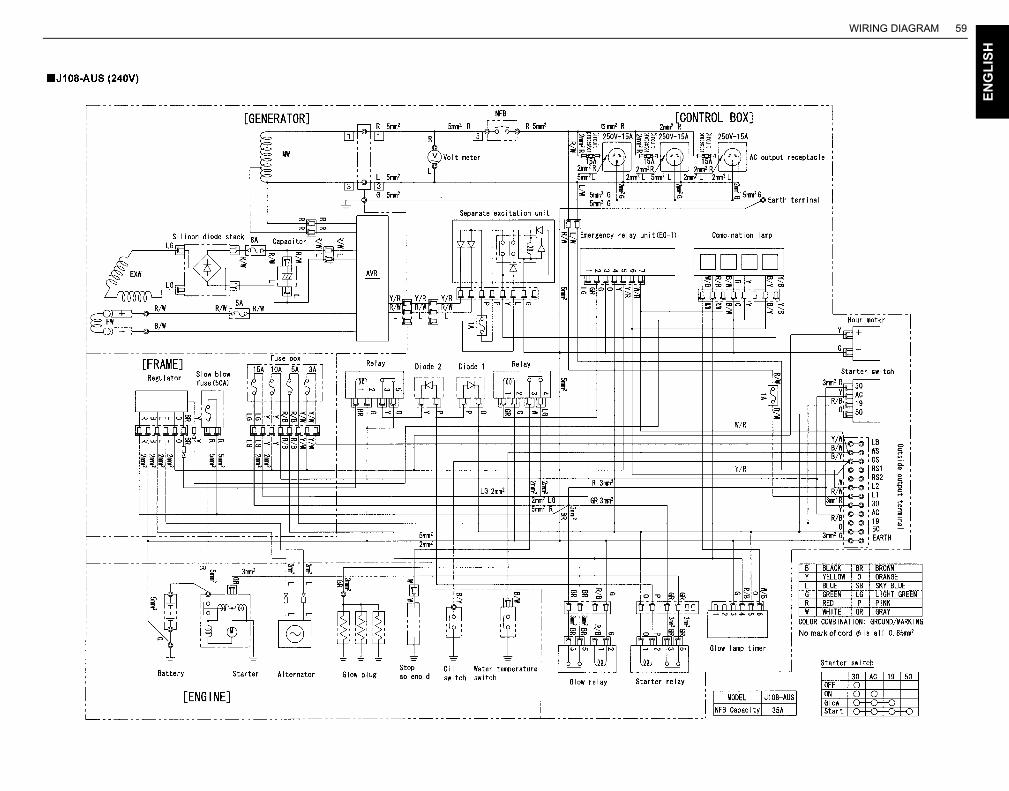
WIRING DIAGRAM 59
EN
GL
ISH
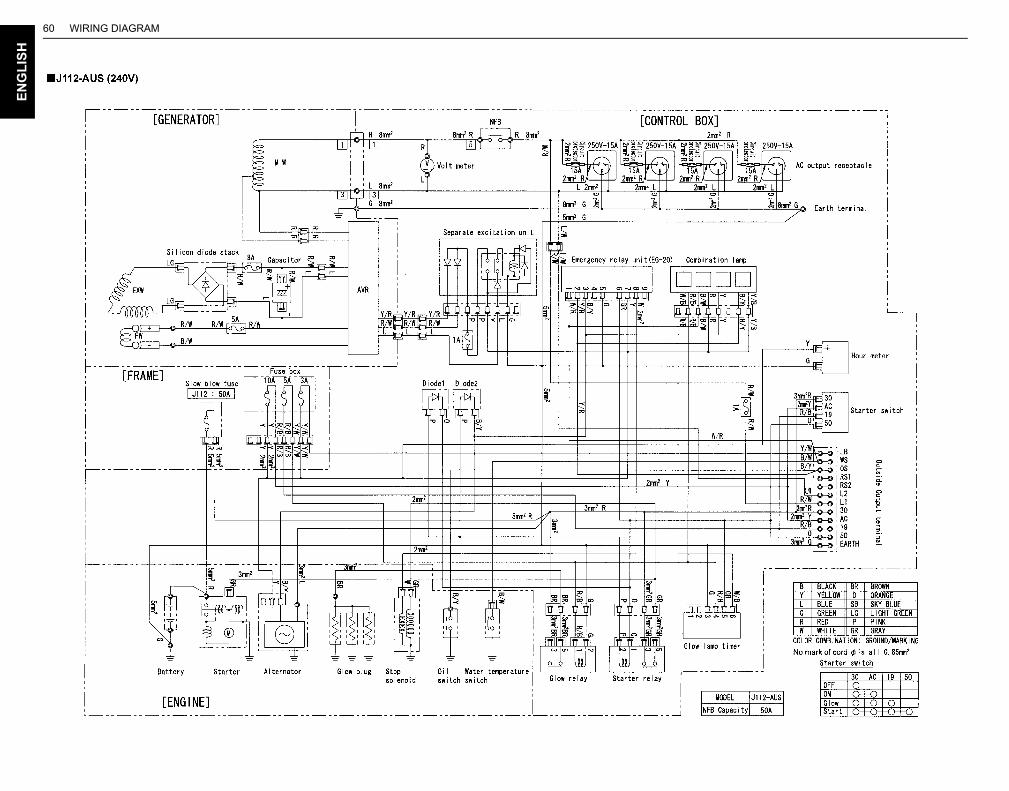
WIRING DIAGRAM60E
NG
LIS
H
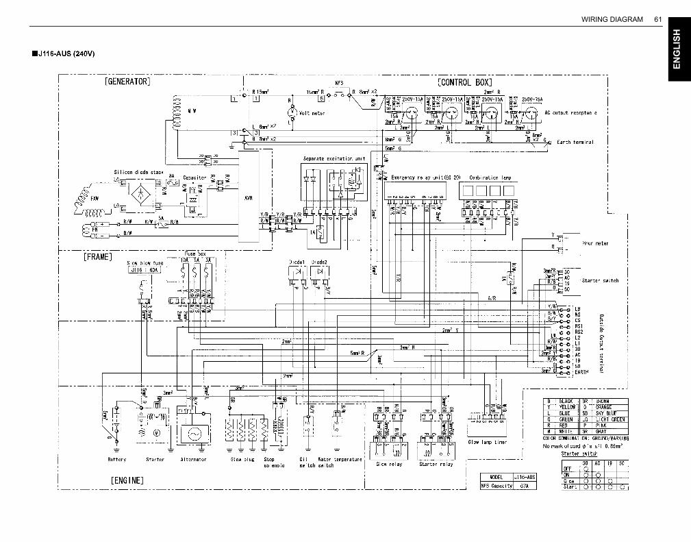
WIRING DIAGRAM 61
EN
GL
ISH
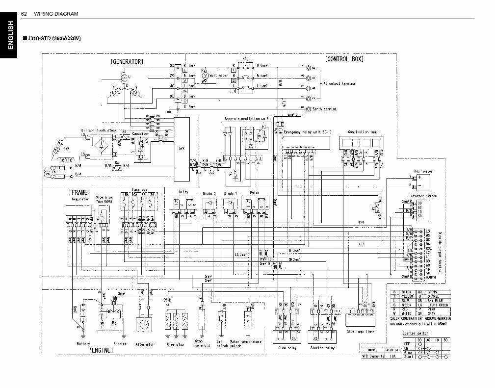
WIRING DIAGRAM62E
NG
LIS
H
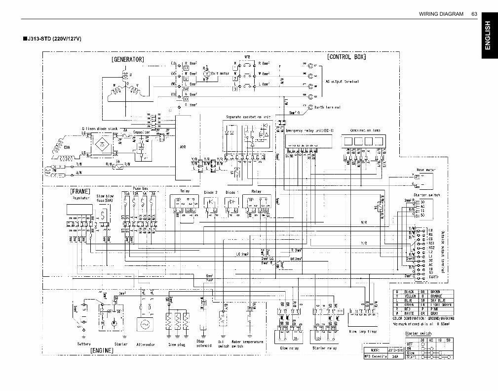
WIRING DIAGRAM 63
EN
GL
ISH
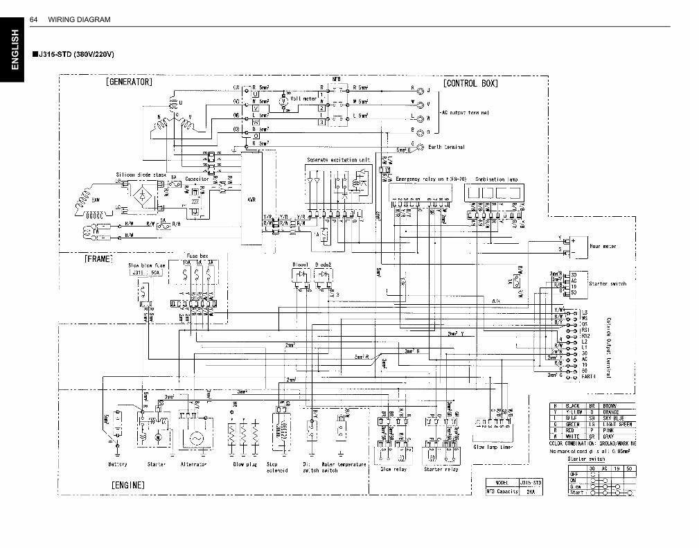
WIRING DIAGRAM64E
NG
LIS
H
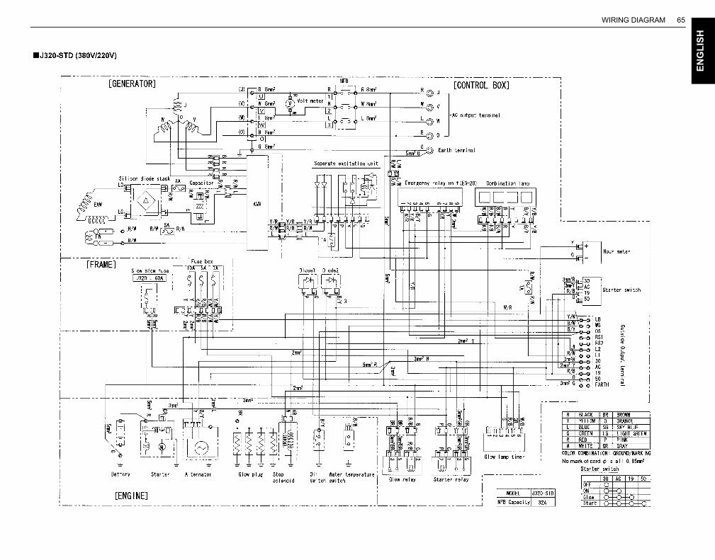
WIRING DIAGRAM 65
EN
GL
ISH

WIRING DIAGRAM66E
NG
LIS
H
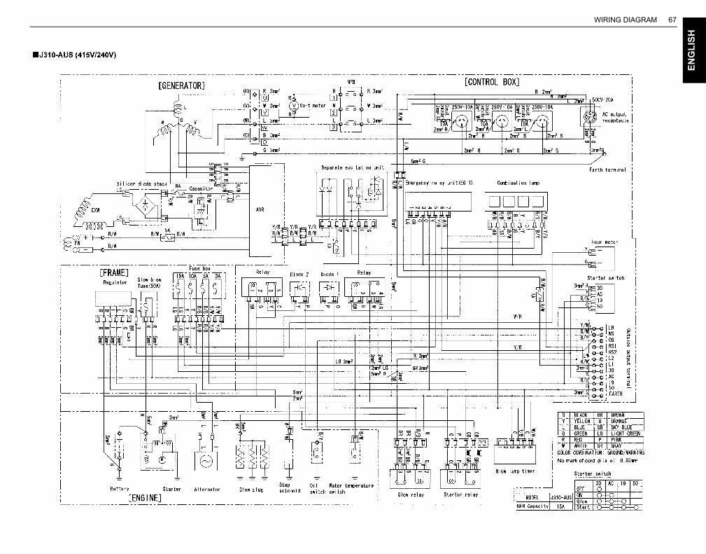
WIRING DIAGRAM 67
EN
GL
ISH
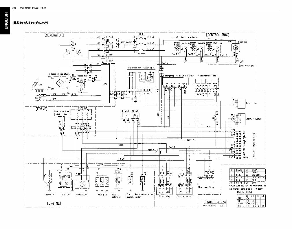
WIRING DIAGRAM68E
NG
LIS
H
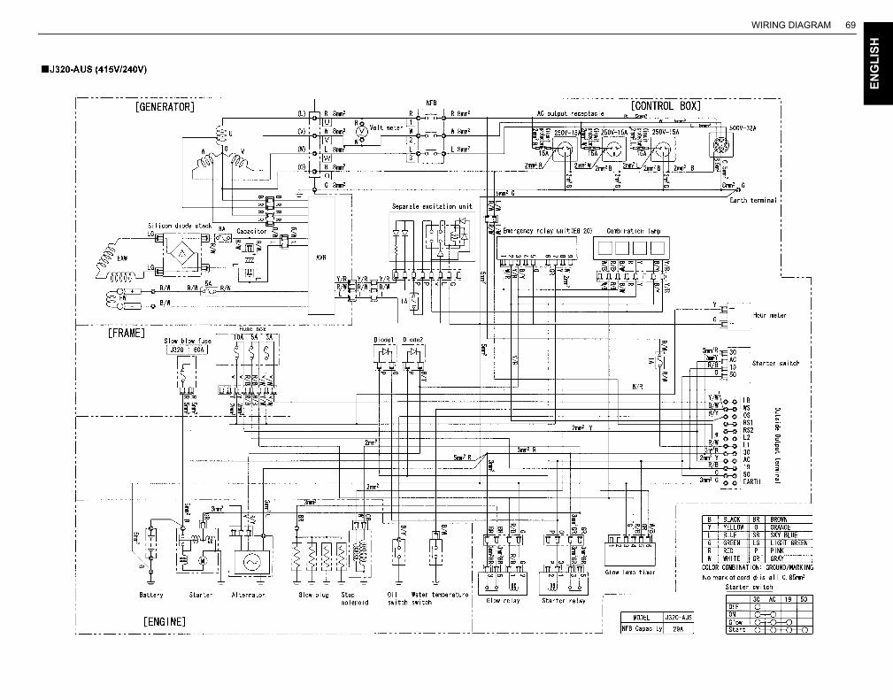
WIRING DIAGRAM 69
EN
GL
ISH