9. personal protective equipment · 9. personal protective equipment ... hold the personal...
TRANSCRIPT

9. PERSONAL PROTECTIVE EQUIPMENT
The cold test pit sites pose low to moderate potential hazards to personnel from construction, operation, and maintenance activities. Anyone entering the cold test pits must be protected against these potential hazards. Personal protective equipment requirements relative to project-specific tasks beyond normal cold test pit maintenance activities will be addressed in appendixes to this HASP and will be incorporated as these tasks are identified.
The purpose of PPE will be to shield or isolate personnel from chemical, physical, or biological hazards that cannot be eliminated through engineering or other controls and that may be encountered at the cold test pit sites. It is important to realize that no PPE ensemble can protect against all hazards under all conditions and that work practices and adequate training also will provide a greater level of protection to workers.
Minimum PPE requirements for work in the cold test pits work control zones are as follows:
Hard hat
Eye protection (safety glasses with side shields)
Sturdy leather boots
Leathers gloves for material handling.
Selection of the proper PPE to protect cold test pit site personnel is based on the following:
Potential routes of entry
Physical form and chemical characteristics of simulated waste components
Acute and chronic effects from exposure to simulated waste components
Local and systemic toxicity of contaminants
Anticipated exposure levels (i.e., surface and airborne)
Hazard evaluation (see Section 8).
The PPE will generally be divided into two broad categories: (1) respiratory protective equipment and (2) personal protective clothing. Both of these categories are incorporated into the standard four levels of protection (i.e., Levels A, B, C, and D) based on the potential severity of cold test pit project hazards. Guidance in the selection process for respiratory and protective clothing is presented in Table 7. Cold test pit site-specific hazards and contaminants will be evaluated in determining the most appropriate PPE level and modifications. See the applicable appendix for project-specific information on PPE requirements.
41

Table 7. Respiratory and protective clothing selection.
Hazard Level of Protection
Respiratory PPE Selection a
Not immediately dangerous to life or health (IDLH) or oxygen deficient atmospheric conditions. Gaseous, vapor, particulate, and aerosol chemicals and radionuclides.
IDLH or oxygen deficient atmospheric conditions. Gaseous, vapor, particulate, and aerosol chemicals and radionuclides.
Protective Clothing Selection
Low atmospheric contaminant levels that are present under stable conditions. No anticipated immersion, splashes, or potential for unexpected contact with chemicals.
Moderate atmospheric contaminants under relatively stable conditions, liquid splashes or other direct contact that do not have corrosive characteristics or can be absorbed by exposed skin. Low radionuclide contamination.
Level C-hll-facepiece, as determined by the industrial hygienist Level B-hll-facepiece supplied air respirator with an air-purifying escape cartridge or airhood (bubblehood)
High-efficiency particulate air or chemical combination cartridge for concentrations up to the protection factor of an air-purifying hll-facepiece respirator
Level B-hll-facepiece, supplied air respirator with an escape-only self-contained breathing apparatus (SCBA) or Level A-SCBA
HEPNchemical combination cartridge for concentrations up to the protection factor of an air-purifying hll-facepiece respirator
Level D
Level C
a. If required, a high-efficiency particulate air or multichemical combination cartridge will be selected by industrial hvgiene Dersonnel based on snecific task hazards.
9.1 Personal Protective Equipment Levels
The following sections provide detail and explanation of the two most likely levels of PPE to be used at the cold test pits. Based on the hazard evaluation and recommendations cited above, the most common level of PPE used at the cold test pits will be Level D. Some potential exists for the requirement to upgrade to a modified Level D or Level C in some site-specific activities. Modifications to these levels will be made under the direction of the HSO in consultation with the project industrial hygienist and safety engineer, as appropriate. Such modifications are routinely employed during HAZWOPER site activities to maximize efficiency and to meet site-specific needs without compromising personnel safety and health.
42
9.1.1 Level D Personal Protective Equipment
Level D PPE, with potential upgrade to a modified Level D, will serve as the primary PPE for cold test pit activities. Level D PPE affords little protection against chemical hazards and provides no protection against airborne chemical hazards. Level D will be appropriate for use when personnel hazardous chemical exposure is not expected to be above an allowable limit and no danger exists because of absorption of chemicals through the skin. Level D is basically a standard work uniform. This level of PPE at the work site consists of the following:
Street clothes and coveralls, as required by the industrial hygienist and safety engineer
Hard hat
Eye protection @e., safety glasses with side shields)
Approved safety footwear, as specified by the safety engineer.
Optional Level D modifications consist of the following:
Chemical protective clothing (e.g., Tyvek and Saranex), as prescribed in the task-specific work control documents
Chemically resistant hand and foot protection (e.g., inner or outer gloves and boot liners)
Any specialized protective equipment (e.g., hearing protection, cryogenic gloves, face shields, and aprons).
9.1.2 Level C Personal Protective Equipment
For normal cold test pit maintenance and operations, Level C PPE is not expected to be required. Level C PPE may be appropriate for some work at the task site when the contaminants are well characterized, the hazard exposure to personnel by skin absorption is minimal, and the threat is very small that an immediately dangerous-to-life-or-health condition will develop. Personnel working at the work site and wearing Level C PPE will wear the following:
Level D ensemble with the following upgrades:
- Chemical-resistant coveralls (i.e., Tyvek QC, Tychem 7500, or Saranex-23-P), as prescribed by the industrial hygienist
- Air purifying respirator
- Chemical-resistant (e.g., rubber and nitrile) outer shoe and boot cover
- Approved safety foot wear, as specified by the safety engineer
- Inner gloves (e.g., rubber and nitrile)
- Outer gloves (e.g., nitrile and rubber)
- Hard hat
43

- Eye protection @e., safety glasses with side shields).
0 Optional Level C modifications:
- Any specialized protective equipment (i.e., hearing protection, welding lens, and aprons).
9.2 Protective Clothing Upgrading and Downgrading
The cold test pit project HSO in consultation with the project industrial hygienist and safety engineer will be responsible for determining when to upgrade or downgrade PPE requirements. Upgrading or downgrading PPE requirements based on current conditions is a normal occurrence. The action levels listed on Table 5 provide the basis for determining such decisions.
Additional reasons for upgrading or downgrading PPE are listed below:
0 Upgrading criteria (work will stop immediately if PPE upgrading is required):
- Unstable or unpredictable site nonradiological hazards
- Contaminants that present difficulty in monitoring or detecting
- Known or suspected presence of skin absorption hazards
- Temporary loss or failure of any engineering controls
- Identified source or potential source of a respiratory hazard
- Change in the task procedure that may result in increased contact with contaminants or meeting any of the criteria listed above.
0 Downgrading criteria:
- New information or monitoring data that shows the contaminant levels to be lower than established action limits
- Implementation of new engineering or administrative controls that eliminate or significantly mitigate hazards
- Elimination of potential skin absorption or contact hazards
- Change in site conditions that results in removal of physical hazards or reduces or isolates them to a controlled area
- Completion or change in tasks that results in the elimination of key hazards that require higher levels of PPE.
9.3 Inspection of Personal Protective Equipment
All PPE ensemble components must be inspected prior to use and when in use within the cold test pit project work zones. Self-inspection and the use of the buddy system, once PPE is donned, will serve as the principal forms of inspection. If at any time, PPE should become damaged or degraded, the worker
44

will inform others of the problem and proceed directly to the work zone exit point to doff and replace the unserviceable equipment. In addition, all PPE that becomes grossly contaminated or presents a potential source for the spread of such contamination will require decontamination or replacement. An inspection checklist for common PPE items is provided in Table 8 .
Table 8 . Personal protection equipment inspection checklist.
Personal Protection Equipment Item Inspection
Rubber gloves Before use:
Pressurize gloves to check for pinholes. Blow in the glove and then roll until air is trapped and inspect. No air should escape.
Levels D and C Before use:
Visually inspect for imperfect seams, nonuniform coatings, and tears. Hold the personal protection equipment (PPE) up to the light and inspect for pinholes, deterioration, stiffness, and cracks.
While wearing PPE in the work zone:
Check for evidence of chemical attack such as discoloration, swelling, softening and material degradation. Inspect for tears, punctures, and zipper or seam damage. Check all taped areas to ensure that they are still intact.
45

I O . DECONTAMINATION PROCEDURES
No known radionuclides are present at the cold test pits. The chemicals used are a minor hazard and do not pose significant contamination concerns. No decontamination procedures apply to the work in this HASP other than those that would be determined by the project industrial hygienist, should a situation requiring such procedures arise.
See the applicable project-specific appendix for information on required decontamination procedures.
46
11. EMERGENCY RESPONSE PLAN FOR COLD TEST PIT SITES
This section defines the responsibilities of the cold test pits and the INEEL ERO by providing an emergency response plan for guidance in responding to abnormal events during treatability study activities.
The emergency response plan addresses OSHA emergency response as defined by the HAZWOPER standard (29 CFR 1910.120 and 1926.65); DOE emergencies as defined by DOE Order 15 1.1 A, “Comprehensive Emergency Management System”; and DOE Order 232.1 A, “Occurrence Reporting and Processing of Operations Information. ” The emergency response plan will be implemented in concert with “INEEL Emergency PladRCRA Contingency Plan” (PLN-114).
The INEEL Emergency Plan may be activated in response to events occurring at cold test pit sites or at the discretion of the emergency coordinator. Once the INEEL Emergency Plan is activated, project personnel will follow the direction and guidance communicated by the emergency coordinator.
Note: The OSHA does not define “emergency” the same as DOE. For simplicity, the term “emergency” is used in this section of the HASP to refer to events covered by either the OSHA or the DOE definition.
This section provides the following emergency response instructions for cold test pit task-site personnel:
0 Emergency warning signals and evacuation routes
0 Personnel accountability procedures
0 Emergency medical services and fire, rescue, and HAZMAT emergency response
0 Task-site emergency communications
0 Emergency equipment and supplies located at the task site
Notification procedures for emergency response to the task site
The cold test pit work tasks do not produce risks that could reasonably be expected to cause an emergency evacuation. Task-site personnel could be affected by an emergency event at an INEEL facility, such as the nearby RWMC.
All emergencies will be reported through the RWMC shift supervisor or facility manager to ERO personnel for classification in accordance with Section 4 of the “INEEL Emergency PladRCRA Contingency Plan,” Addendum 3 (PLN-114). If a facility ERO is activated, task-site emergency response will follow the “INEEL Emergency PladRCRA Contingency Plan,” Addendum 3 (PLN-114).
Response to and mitigation of task-site emergencies will require the expertise of both task-site personnel and INEEL emergency response personnel. Examples of emergencies that could occur include the following:
0 Accidents resulting in injury
Accidents resulting in chemical exposure of personnel
47

0 Fires
0 Explosions
0 Spills of hazardous materials
Tornadoes, earthquakes, and other adverse natural phenomena
Vehicle or transportation emergencies
Emergencies at nearby facilities or wildfires that could prompt evacuation or take-cover actions at the task site.
11 .I Types of Emergency Events
Note: This HASP addresses three types of emergency events, as described in the following sections. Each event type may require a diflerent response action by project personnel, but all events will be reported to the R WMC shift supervisor.
11 .I .I Events Requiring Emergency Notifications But No Evacuation
Certain events require courtesy notifications but do not require a response from the INEEL ERO. In these cases, the field team leader, subcontract technical representative, or project designee will immediately notify personnel identified in Section 1 1.5 of this HASP (the RWMC shift supervisor, the Warning Communications Center [WCC], INEEL subcontractor project and department personnel including the WAG 7 manager of projects who will notify DOE) and other appropriate parties as listed in Section 11.8. The notification should describe the event and state that no emergency response support is required. Examples of these types of events include, but are not limited to, the following:
Personal injury at the site that requires medical evaluation or treatment but does not require an ambulance response
Personnel contamination or suspected uptake of a hazardous substance not requiring emergency medical treatment
Equipment or vehicle accident that results in damage to the vehicle or property ONLY
A small fire that can be controlled with a hand-held fire extinguisher (all fires must be reported to the INEEL fire department)
0 Any spill as defined by MCP-3480, “Environmental Instructions for Facilities, Materials and Equipment”
Any other event deemed potentially reportable.
11 .I .2 Events Requiring Cold Test Pit Evacuation or Emergency Response Organization Response
Some events that could occur at the project or the RWMC may require support from the RWMC ERO or may require a local area evacuation of the project. In these cases, the project field team leader,
48

subcontract technical representative, or project designee, who is the appointed project area warden, will immediately notify the RWMC shift supervisor, the WCC, cold test pit subcontractors, the WAG 7 manager of projects (who will notify DOE), and other appropriate parties as listed in Section 11.8. The notification will describe the event and request emergency response resources, as appropriate. After being informed of the event, the emergency coordinator may elect to activate the RWMC command post. Once the command post is declared operational, all emergency response activities will be coordinated through the emergency coordinator. The specific actions to be taken in response to emergency alarms are described in Section 1 1.5. Examples of these types of events include, but are not limited to, those listed below:
A fire that is burning beyond an incipient stage and requires a response from the INEEL Fire Department to mitigate
A large spill at the project that cannot be immediately contained or controlled
0 A serious injury or rescue of a worker or workers.
11 .I .3 Events Requiring Radioactive Waste Management Complex and Cold Test Pit Evacuation
No credible scenarios could or would result in the total evacuation of the RWMC from a cold test pit emergency event. In the event that an RWMC emergency requires evacuation of the cold test pits, the field team leader, subcontract technical representative, or project designee will be notified by the ERO to evacuate all cold test pit personnel. The RWMC emergency coordinator will be responsible for ordering a total area evacuation protective action that may include the cold test pit areas.
Note: When an evacuation is called for by the emergency coordinator, thejeld team leader, subcontract technical representative, or project designee will be the designatedproject area warden who will ensure that the ERO personnel accountability leader has been notijed that all cold test pit workers have been evacuated and oersonnel accountabilitv has been comoleted.
11.2 Emergency Facilities and Equipment
Emergency response equipment that is maintained at the cold test pits includes the items described in Table 9. Addendum 3 to the INEEL Emergency Plan lists emergency equipment available at the RWMC. This includes the command post located in Building WMF-637, equipment located in Building WMF-60 1 (i.e., self-contained breathing apparatus [SCBA] dosimeters, air samplers, decontamination, first-aid equipment), and an emergency response trailer. The INEEL Fire Department maintains an emergency HAZMAT response van that can be used to respond to an event or emergency at the cold test pits. Fire department personnel are also trained to provide immediate HAZMAT spills, rescue, and medical services. At least two people with current medic or first-aid training will be present at the cold test pits during all work activities (except cold test pit area monitoring and surveillance) to render first aid, as required. The cold test pit HSO and industrial hygiene personnel may assist with emergency decontamination efforts. Emergency equipment requirements relative to proj ect-specific tasks beyond normal cold test pit maintenance and operations activities will be addressed in appendixes to this HASP and will be incorporated as these tasks are identified.
49

Table 9. Emeraencv response eauipment to be maintained at the task site.
Equipment Name and Location at Frequency of Quantity Required Task Site Responsible Person Inspection
Fire extinguishers Located throughout the cold Health and safety Monthly test pit areas and on all heled equipment
officer (HSO)
First-aid kit Administration area HSO Monthly
Eyewash bottles” Administration area HSO Monthly
Eyewash station” Administration area
Hazardous materials Administration area spill kitb
HSO Monthly
HSO Monthly
Communication Onsite Field team leader Availability and equipment available hnctional check a. Eyewash bottles, stored in the administration area, Will be used in the control zone, when required, to provide an immediate eye flush. An eyewash station that meets the American National Standards Institute Z 358.1-1990 requirements is available in the administration area and will be moved to the control zone, when required. b. The still lut is stored in the administration area and will be moved to the control zone. when reauired.
11.3 Emergency Communications
In the event of an emergency, the capability to summon INEEL emergency response resources, to immediately notify site personnel, and to inform others of site emergencies is required.
Communications equipment at the task site will be a combination of pagers, radios, and telephones (e.g., mobile, cellular, or land lines).
The following actions, as necessary, will be taken for emergency situations:
0 Call 777, the INEEL site emergency telephone number or 526-15 15, the WCC. Once the initial call is made, the field team leader, subcontract technical representative, project designee, or HSO may use the E-NET radio to update emergency response personnel.
Notify site personnel to evacuate to the designated marshalling or take-cover area by use of verbal communications, radios, cell phones, or a hand-held air horn with intermittent blasts.
Notify site personnel to take cover using a continuous blast of the air horn.
Contact the RWMC shift supervisor or facility manager by radio or telephone
0 The RWMC shift supervisor will contact the RWMC ERO
Site personnel should provide the following information, as available, when communicating emergency information to the INEEL site emergency telephone number, the WCC, or the point of contact:
The caller’s name, telephone number, radio call sign, and pager number
50

Exact location of the emergency
Nature of the emergency, including time of occurrence, current site conditions, and special hazards in the area
0 Injuries, if any, including number of injured, types of injuries, conditions of injured
0 Additional information, as requested
11.4 Emergency Response Roles and Responsibilities
11.4.1 Emergency Response Organizations
The INEEL ERO structure is based on the incident command system. The incident command system is an emergency management system designed for use from the time an incident occurs and will be responded to until it is terminated. The system consists of procedures for controlling personnel, facilities, equipment, and communications. It allows for activating emergency response resources in a graded approach depending on the nature and seriousness of the event. At the cold test pits, the incident command system is implemented as a chain of command operating on three basic levels: (1) the on-scene commander, (2) the RWMC command post, and ( 3 ) the INEEL Emergency Operations Center.
77.4.7.7 tactical and command responsibility for the control of an emergency situation at the scene, a fire, HAZMAT response, and as a special rescue response. The senior fire department officer responding for the INEEL Fire Department fills this position. If the event is primarily a security incident, the senior responding protective forces officer will assume the duties of the on-scene commander. In some instances, the incident response team leader may hnction as the on-scene commander until relieved by a higher-tiered authority. The incident response team leader reports to the on-scene commander who reports to the emergency coordinator. The incident response team acts at the first responder awareness level by providing initial-control personal-protective measures and incident assessment and mitigation, as directed by the incident response team leader.
On-Scene Commander. The on-scene commander (as specified in PLN-114) has the
The project field team leader, subcontract technical representative, project designee, and will be trained at the first responder awareness level and will:
Understand the potential outcomes associated with an emergency when hazardous substances are present
Understand what hazardous substances are and their associated risks in an incident
Recognize the presence of hazardous substances in an emergency
Identify the hazardous substances, if possible
Assume the roles of a first responder at the awareness level
0 Realize and understand the need for additional resources
7 7.4.7.2 Radioactive Waste Management Complex Command Post. The RWMC command post is the second tier of the emergency response line organization and will be headed by the emergency coordinator. The emergency coordinator will be responsible for all emergency response actions within the
51

entire facility including advising the on-scene commander. The command post will be activated for actual or potential emergencies or at the direction of the emergency coordinator. If the command post is activated in response to an event at the project, then the project will send a representative to the command post to advise the emergency coordinator.
7 7.4.7.3 the ERO and is headed by the INEEL emergency director. The emergency director will be responsible for all emergency response actions at the INEEL including advising the emergency coordinator. cold test pit personnel do not normally provide direct support to the Emergency Operations Center.
Emergency Operations Center. The Emergency Operations Center is the upper tier of
11.4.2 Project Personnel Involved in Emergencies
77.4.2.7 Field Team Leader, Subcontract Technical Representative, or Project Designee. The field team leader, subcontract technical representative, project designee, or the HSO will be responsible as the designated project first responder at the awareness level for initiating all requests for emergency services (e.g., fire and medical) and for notifying the facility shift supervisor of abnormal or potential abnormal events occurring on the project. The field team leader, subcontract technical representative, or project designee serves as the project area warden. In this capacity, the field team leader, subcontract technical representative, or project designee will report the accountability for all employees to the personnel accountability leader when an emergency evacuation is called. In addition, the field team leader, subcontract technical representative, or project designee will control the scene at the first responder awareness level until relieved by a higher-tiered incident command system authority at the scene to take control as the on-scene commander. While maintaining control of the scene from a protected and controlled distance, the field team leader, subcontract technical representative, or project designee will maintain communication with the facility shift supervisor or the emergency coordinator when the emergency communication system is in place.
77.4.2.2 emergency. Each employee must be constantly aware of potential problems or unexpectedly hazardous situations by immediately reporting these situations to the field team leader, subcontract technical representative, project designee, or HSO. All employees are expected to watch out for their fellow workers; to report their concerns to the field team leader, subcontract technical representative, or project designee; and to respond to emergency events as provided for in this HASP. Specific project personnel responsibilities are outlined in Table 10.
Project Personnel. Every person at the project has a role to play during an event or INEEL
11.5 Emergencies, Recognition of Warnings, and Response
11 S.1 Emergency Recognition and Response
All task-site personnel should be constantly alert for signs of potentially hazardous situations, including signs and symptoms of chemical exposures or equipment failure or collapse. All personnel entering the cold test pit areas will be trained on the methods, signals, and alarms used to convey “EVACUATION” and “TAKE COVER’ and on the expected responses. Cold test pit personnel will also be trained (during the training for this HASP) on the following immediate response actions:
Assembling task-site personnel at the designated assembly point of the RWMC for an evacuation of the cold test pits
Summoning the INEEL emergency response by calling 777 (INEEL site emergency telephone number) or the WCC at 526-1515
52
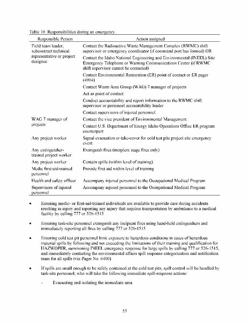
Table 10. Responsibilities during an emergency. Responsible Person Action assigned
Field team leader, subcontract technical representative or project designee
WAG 7 manager of projects
Any project worker
Any extinguisher- trained project worker Any project worker Medic first-aid-trained personnel Health and safety officer Supervisors of injured personnel
Contact the Radioactive Waste Management Complex (RWMC) shift supervisor or emergency coordinator (if command post has formed) OR Contact the Idaho National Engineering and Environmental (INEEL) Site Emergency Telephone or Warning Communications Center (if RWMC shift supervisor cannot be contacted) Contact Environmental Restoration (ER) point of contact or ER pager (4904) Contact Waste Area Group (WAG) 7 manager of projects Act as point of contact Conduct accountability and report information to the RWMC shift supervisor or personnel accountability leader Contact supervisors of injured personnel Contact the vice president of Environmental Management Contact U. S. Department of Energy Idaho Operations Office ER program counterpart Signal evacuation or take-cover for cold test pits project site emergency event Extinguish fires (incipient stage fires only)
Contain spills (within level of training) Provide first aid within level of training
Accompany injured personnel to the Occupational Medical Program Accompany injured personnel to the Occupational Medical Program
Ensuring medic- or first-aid-trained individuals are available to provide care during accidents resulting in injury and reporting any injury that requires transportation by ambulance to a medical facility by calling 777 or 526-15 15
0 Ensuring task-site personnel extinguish any incipient fires using hand-held extinguishers and immediately reporting all fires by calling 777 or 526-1515
Ensuring cold test pit personnel limit exposure to hazardous conditions in cases of hazardous material spills by following and not exceeding the limitations of their training and qualification for HAZWOPER, summoning INEEL emergency response for large spills by calling 777 or 526-15 15, and immediately contacting the environmental affairs spill response categorization and notification team for all spills (via Pager No. 6400)
If spills are small enough to be safely contained at the cold test pits, spill control will be handled by task-site personnel, who will take the following immediate spill-response actions:
- Evacuating and isolating the immediate area
53

- Seeking help from and warning others in the area
- Stopping the spill, if it can be done without risk (e.g., returning the container to the upright position, closing valve, shutting off power)
- Providing pertinent information to the field team leader, subcontract technical representative, and the HSO
- Securing any ventilation paths and ensuring that the industrial hygienist or safety engineer surveys the area to determine the extent of a chemical spill, as appropriate.
Emergency drills will be conducted relative to project-specific tasks beyond normal cold test pit maintenance and operations activities, and will be addressed in appendixes to this HASP, which will be incorporated as these tasks are identified. The purpose of these drills will be to familiarize employees with their respective emergency response actions. Any radio or telephone communications that are included in drills will be immediately preceded and followed with a statement that “This is a drill” to prevent an actual emergency response from being initiated by WCC. Each drill or actual emergency at the cold test pits will be followed by a critique and any identified deficiencies in the emergency plan will be corrected.
11 S.2 Alarms
Alarms and signals are used at the cold test pits and INEEL to notify personnel of abnormal conditions that require a specific response. Responses to these alarms are addressed in the general employee training. In addition to the alarms previously described, emergency sirens located throughout the RWMC serve as the primary means for signaling emergency TAKE COVER or EVACUATION protective actions. To signal site personnel of a proj ect-initiated emergency event, emergency signals have been established based on using hand-held air or vehicle horns. These signals are described in Table 11.
Table 11. Proiect internal and backuz, emergencv air-horn signals.
Device or Communication Method Signal Associated Response
Air horns (blasts) One continuous blast Take cover.
Multiple short blasts (until all personnel react and begin evacuation) assembly area.
Three long blasts
Local area evacuation. Leave immediate work area and proceed to project
Return to site-all clear.
77.5.2.7 building. A TAKE COVER protective action may be initiated as part of a broader response to an emergency situation and may precede an evacuation order. The order to TAKE COVER is usually announced by activating a hand-held air horn. The signal to take cover will be a continuous blast that can be heard throughout the cold test pit areas. Remember, STEADY = STAY at the cold test pits. But the order to TAKE COVER can also be given by word of mouth, radio, or voice paging system. When ordered to TAKE COVER, project personnel will place the site in a safe condition (as appropriate) and then seek shelter in the project support or cold test pit administration trailer. Vehicles may be used for shelter if there are no buildings nearby. Eating, drinking, and smoking are not permitted during TAKE COVER conditions.
Take Cover. Emergency conditions may require that all personnel take cover in the nearest
54

77.5.2.2 from the project site and the entire RWMC area. The evacuation signal is an ALTERNATING SIREN that can be heard throughout the RWMC. Remember, ALTERNATE = EVACUATE. However, the order to evacuate can also be given by word of mouth, radio, or voice paging system. When ordered to EVACUATE, project personnel will place the cold test pit area in a safe condition (as appropriate) and then proceed along the specified evacuation route to the designated assembly area (WMF-637) or as directed by the emergency coordinator.
Total Area Evacuation. A total area evacuation is the complete withdrawal of personnel
For total area evacuations, the RWMC command post is activated and all personnel gather at the primary RWMC evacuation assembly area or the location designated by the emergency coordinator. Following a project evacuation, the field team leader, subcontract technical representative, or project designee will conduct accountability and report the results to the identified RWMC personnel accountability leader or RWMC emergency coordinator.
77.5.2.3 personnel from a project control zone, but it does not require the complete evacuation of the entire cold test pit areas. The order to evacuate can be given by word of mouth, radio, or voice paging system. When ordered to evacuate the local area, project personnel will place the project site in a safe condition (as appropriate) and then proceed along the specified evacuation route to the assembly area designated for local area evacuations or as directed by the field team leader or subcontract technical representative. Eating, drinking, and smoking are not permitted during emergency evacuations.
11 5 3
Local Area Evacuation. A local area evacuation will be the complete withdrawal of
Personnel Accountability and Area Warden
Project personnel are required to evacuate the site in response to TAKE COVER and LOCAL AREA EVACUATION alarms. In each case, the project area warden will account for the people present on the site at the time the alarm was initiated. The field team leader, subcontract technical representative, or project designee serves as the area warden for the project and completes the personnel accountability based on the sign-in roster used to control site access. As described next, the method used to report the results of the accountability process varies depending on the nature of the emergency event.
For total area evacuations, the RWMC command post will be activated and all personnel will gather at the evacuation assembly area designated by the emergency coordinator. In this situation, the project area warden reports the results of the accountability process to the RWMC personnel accountability leader.
The RWMC command post will also be activated for TAKE COVER alarms; however, personnel remain in the closest appropriate shelter. In this situation, a complete personnel accountability report will not be required, but the cold test pit area warden should report the results of the accountability process to the RWMC command post or shift supervisor.
The RWMC command post is not usually activated for a cold test pit local area evacuation. In this situation, a complete personnel accountability report will not be required, but the project area warden should report the results of the accountability process to the RWMC shift supervisor who will provide the information to the RWMC facility manager.
11 5 4 Notifications
As directed by the office of the Secretary of Energy, the RWMC area director will be responsible for immediately notifying the DOE and local agencies off-Site of all significant abnormal events that occur at the cold test pits. This duty will be in addition to the notification requirements established in INEEL procedures for events that are categorized as emergencies or unusual occurrences. For this reason,
55
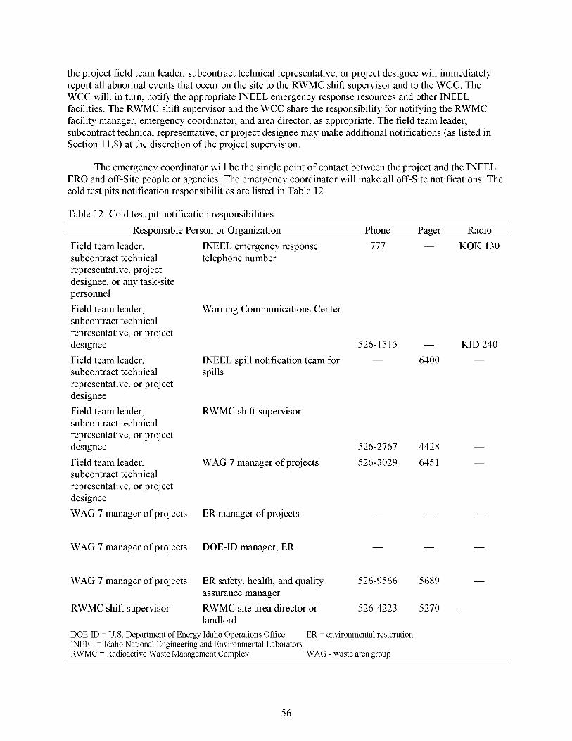
the project field team leader, subcontract technical representative, or project designee will immediately report all abnormal events that occur on the site to the RWMC shift supervisor and to the WCC. The WCC will, in turn, notify the appropriate INEEL emergency response resources and other INEEL facilities. The RWMC shift supervisor and the WCC share the responsibility for notifying the RWMC facility manager, emergency coordinator, and area director, as appropriate. The field team leader, subcontract technical representative, or project designee may make additional notifications (as listed in Section 11.8) at the discretion of the project supervision.
The emergency coordinator will be the single point of contact between the project and the INEEL ERO and off-Site people or agencies. The emergency coordinator will make all off-Site notifications. The cold test pits notification responsibilities are listed in Table 12.
Table 12. Cold test pit notification responsibilities. Responsible Person or Organization Phone Pager Radio
Field team leader, subcontract technical representative, project designee, or any task-site personnel Field team leader, subcontract technical representative, or project designee Field team leader, subcontract technical representative, or project designee Field team leader, subcontract technical representative, or project designee Field team leader, subcontract technical representative, or project designee WAG 7 manager of projects
WAG 7 manager of projects
WAG 7 manager of projects
RWMC shift supervisor
INEEL emergency response 777 - KOK 130 telephone number
Warning Communications Center
526-1515 - KID 240 - INEEL spill notification team for 6400 -
spills
RWMC shift supervisor
526-2767 4428 -
WAG 7 manager of projects 526-3029 645 1 -
ER manager of projects - - -
DOE-ID manager, ER - - -
ER safety, health, and quality 526-9566 5689 -
assurance manager
landlord RWMC site area director or 526-4223 5270 -
~
DOE-ID = U.S. Department of Energy Idaho Operations Office WEEL = Idaho National Engineering and Environmental Laboratory RWMC = Radioactive Waste Management Complex
ER = environmental restoration
WAG - waste area group
56
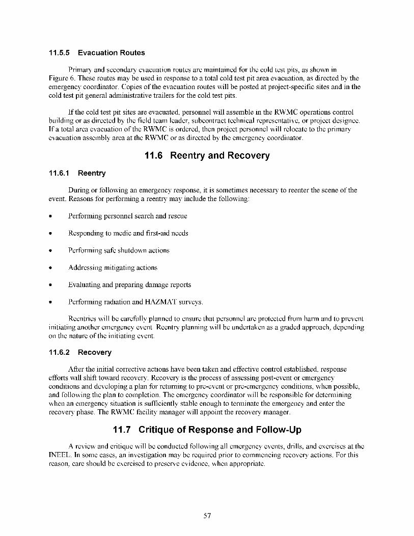
11 5 5 Evacuation Routes
Primary and secondary evacuation routes are maintained for the cold test pits, as shown in Figure 6. These routes may be used in response to a total cold test pit area evacuation, as directed by the emergency coordinator. Copies of the evacuation routes will be posted at project-specific sites and in the cold test pit general administrative trailers for the cold test pits.
If the cold test pit sites are evacuated, personnel will assemble in the RWMC operations control building or as directed by the field team leader, subcontract technical representative, or project designee. If a total area evacuation of the RWMC is ordered, then project personnel will relocate to the primary evacuation assembly area at the RWMC or as directed by the emergency coordinator.
11.6 Reentry and Recovery
11.6.1 Reentry
During or following an emergency response, it is sometimes necessary to reenter the scene of the event. Reasons for performing a reentry may include the following:
0
0
0 Performing safe shutdown actions
0 Addressing mitigating actions
0
0
Performing personnel search and rescue
Responding to medic and first-aid needs
Evaluating and preparing damage reports
Performing radiation and HAZMAT surveys.
Reentries will be carehlly planned to ensure Lat personnel are protected from harm and to prevent initiating another emergency event. Reentry planning will be undertaken as a graded approach, depending on the nature of the initiating event.
11.6.2 Recovery
After the initial corrective actions have been taken and effective control established, response efforts will shift toward recovery. Recovery is the process of assessing post-event or emergency conditions and developing a plan for returning to pre-event or pre-emergency conditions, when possible, and following the plan to completion. The emergency coordinator will be responsible for determining when an emergency situation is sufficiently stable enough to terminate the emergency and enter the recovery phase. The RWMC facility manager will appoint the recovery manager.
11.7 Critique of Response and Follow-Up
A review and critique will be conducted following all emergency events, drills, and exercises at the INEEL. In some cases, an investigation may be required prior to commencing recovery actions. For this reason, care should be exercised to preserve evidence, when appropriate.
57
\
4
58
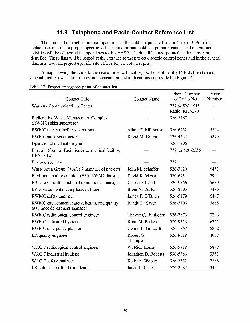
11.8 Telephone and Radio Contact Reference List
The points of contact for normal operations at the cold test pits are listed in Table 13. Point of contact lists relative to project-specific tasks beyond normal cold test pit maintenance and operations activities will be addressed in appendixes to this HASP, which will be incorporated as these tasks are identified. These lists will be posted at the entrance to the project-specific control zones and in the general administrative and project-specific site offices for the cold test pits.
A map showing the route to the nearest medical facility, locations of nearby INEEL fire stations, site and facility evacuation routes, and evacuation pickup locations is provided in Figure 7.
Table 13. Proiect emergencv point of contact list. Phone Number Pager
Contact Title Contact Name or Radio Net Number Warning Communications Center
Radioactive Waste Management Complex (RWMC) shift supervisor RWMC nuclear facility operations RWMC site area director Operational medical program First aid (Central Facilities Area medical facility,
Fire and security Waste Area Group (WAG) 7 manager of projects Environmental restoration (ER) -RWMC liaison ER safety, health, and quality assurance manager ER environmental compliance officer RWMC safety engineer RWMC environment, safety, health, and quality assurance department manager RWMC radiological control engineer RWMC industrial hygiene RWMC emergency planner ER quality engineer
CFA- 16 12)
WAG 7 radiological control engineer WAG 7 industrial hygiene WAG 7 safety engineer ER cold test Dit field team leader
Albert E. Millhouse David M. Bright
-
John M. Schaffer David R. Moser Charles Chebul Brent N. Burton James F. O’Brien Randy D. Sayer
Thayne C. Butikofer Brian M. Perkes Gerald L. Gibeault Robert G. Thompson W. &ck Home Jonathon D. Roberts Kelly A. Wooley
777 or 526-1515 Radio: KID-240 526-2767
526-6932 526-4223 526- 1596 777. or 526-2356
777 526-3029 526-6934 526-9566 526-8695 526-5 179 526-5706
526-7873 526-9358 526-1767 526-96 18
526-53 18 536-53 86 526-2552
Jason L. CasDer 526-2682
-
-
5304 5270 -
-
-
645 1 7994 5689 7486 6447 5865
3296 6355 5802 4067
5898 335 1 7368 3434
59
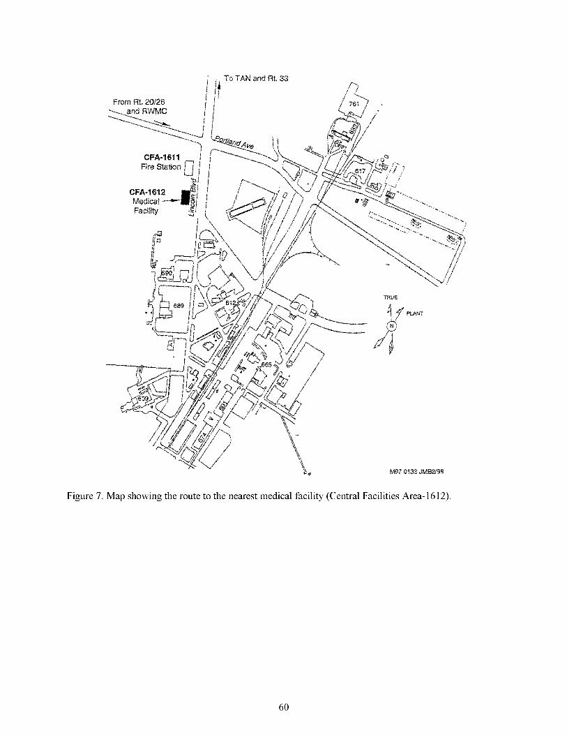
Figure 7. Map showing the route to the nearest medical facility (Central Facilities Area-1612).
60

12. REFERENCES
29 CFR 19 10.120, 2002, Title 29, “Labor,” Part 1910, “Occupational Safety and Health Administration,” Subpart H, “Hazardous Materials,” Section 19 10.120, “Hazardous Waste Operations and Emergency Response,” Code of Federal Regulations, Office of the Federal Register, February 8, 2002.
29 CFR 1926.65, 2002, Title 29, “Labor,” Part 1926, “Safety and Health Regulations for Construction,” Subpart D, “Occupational Health and Environmental Controls,” Section 1926.65, “Hazardous Waste Operations and Emergency Response,” Code of Federal Regulations, Office of the Federal Register, April 15, 2002.
49 CFR 171.8,2002, Title 49, “Transportation,” Part 171, “General Information, Regulations, and Definitions,” Section .8, “Definitions and Abbreviations,” Code of Federal Regulations, Office of the Federal Register, April 3, 2002.
54 FR 29820, 1998, “National Oil and Hazardous Substances Pollution Contingency Plan,” Federal Register, U.S. Environmental Protection Agency, December 15, 1998.
54 FR 48 184, 1989, “National Priorities List of Uncontrolled Hazardous Waste Sites; Final Rule,” Federal Register, U. S. Environmental Protection Agency. November 2 1, 1989
42 USC 9 4321 et seq., 1970, “National Environmental Policy Act,” United States Code.
42 USC 9 6901 et seq., 1976, “Resource Conservation and Recovery Act (Solid Waste Disposal Act),” United States Code.
42 USC 9 9601 et seq., 1980, “Comprehensive Environmental Response, Compensation and Liability Act of 1980 (CERCLAKuperhnd),” United States Code.
DOE 0 15 1. lA, November 1,2000, “Comprehensive Emergency Management System,” U. S. Department of Energy.
DOE 0 232. lA, July 21, 1997, “Occurrence Reporting and Processing of Operations Information,” U. S. Department of Energy.
Becker, B. H., J. D. Burgess, K. J. Holdren, D. K. Jorgensen, S. 0. Magnuson, and A. J. Sondrup, 1998, Interim Risk Assessment and Contaminant Screening for the Waste Area Group 7 Remedial Investigation, DOE/ID- 10569, U. S. Department of Energy Idaho Operations Office, Idaho Falls, Idaho, August.
Becker, B. H., T. A. Bensen, C. S. Blackmore, D. E. Burns, B. N. Burton, N. L. Hampton, R. M. Huntley, R. W. Jones, D. K. Jorgensen, S. 0. Magnuson, C. Shapiro, and R. L. VanHorn, 1996, WorkPlan for Operable Unit 7-1 3/14 Waste Area Group 7 Comprehensive Remedial Investigation/Feasibility Study, INEL-95/0343, Idaho National Engineering and Environmental Laboratory, Lockheed Martin Idaho Technologies Company, Idaho Falls, Idaho.
DOE-ID, 2000, Quality Assurance Project Plan for Waste Area Groups 1, 2, 3, 4, 5, 6, 7, 10 and Inactive Sites, DOE/ID-10587, Rev. 6, U.S. Department of Energy Idaho Operations Office, Idaho Falls, Idaho.
61

DOE-ID, 199 1, Federal Facility Agreement and Consent Order for the Idaho National Engineering Laboratory, U. S. Department of Energy, Idaho Field Office; U. S. Environmental Protection Agency, Region 10; Idaho Department of Health and Welfare, December 4, 199 1.
DOE-ID, 1987, Consent Order and Compliance Agreement, U.S. Department of Energy, Idaho Field Office; U. S. Environmental Protection Agency, Region 10; and the U. S. Geological Survey, July 10, 1987.
DOE-STD-1090-01,2001, “Hoisting and Egging,” U.S. Department of Energy, April 2001
EG&G, 1985, A History of the Radioactive Waste Management Complex at the Idaho National Engineering Laboratory, WM-F 1-8 1-003, Rev. 3, Idaho National Engineering and Environmental Laboratory, EG&G Idaho, Idaho Falls, Idaho.
Farnsworth, R. K., D. J. Henrikson, R. A. Hyde, D. K. Jorgensen, J. K. McDonald, D. F. Nickelson, M. C. Pfeifer, P. A. Sloan, and J. R. Weidner, March 1999, Operable Unit 7-13/14 In Situ Vitrzjcation Treatability Study Work Plan, DOE/ID- 10667, U. S. Department of Energy Idaho Operations Office, Idaho Falls, Idaho.
Form 340.02, 2001, “Employee Job Function Evaluation,” Rev. 8, February 13,2001.
Form 361.25, 1999, “Group Read & Sign Training Roster,” Rev. 1, May 10, 1999.
Form 36 1.47, 200 1, “Hazardous Waste Operations (Hazwoper) Supervised Field Experience Verification 29 CFR 1910.120,”Rev. 5, July 18, 2001.
Form 412.11,2001, “Document Management Control Systems (DMCS) Document Action Request (DAR),” Rev. 6, August 9, 2001.
IAG-20, 2002, “Interface Agreement Between Radioactive Waste Management Complex and Environmental Restoration,” Rev. 0, May 6, 2002.
Loomis, Guy G., James J. Jessmore, and Jerry R. Weidner, 2001, Implementation Test and Field Test Plan for the Operable Unit 7-1 3/14 In Situ Grouting Treatability Study, INEEL/EXT-2000-00449, Rev. 1, Idaho National Engineering and Environmental Laboratory, Bechtel BWXT Idaho, LLC, Idaho Falls, Idaho.
MCP- 153, 2002, “Industrial Hygiene Exposure Assessment,” Rev. 5, Information Resources Management, April 17, 2002.
MCP-23 1, 2000, “Logbooks for ER and D&D&D Projects,” Rev. 4, July 11, 2000.
MCP-255, 2002, “Hazardous Waste Operations and Emergency Response Activity Health and Safety Plans,” Rev. 5, April 17, 2002.
MCP-553, 200 1, “Stop Work Authority,” Rev. 5, Information Resources Management, November 16,200 1.
MCP-5 84, 1997, “Flammable and Combustible Liquid Storage and Handling,” Rev. 2, Information Resources Management, February 1, 1997.
62

MCP-2704, 2002, “Controlling Exposure to Heat and Cold Stress,” Rev. 2, Information Resources Management, April 17, 2002.
MCP-27 19, 2002, “Controlling and Monitoring Exposure to Noise,” Rev. 2, Information Resources Management, April 17, 2002.
MCP-2743, 200 1, “Motor Vehicle Safety,” Rev. 2, Information Resources Management, January 9, 200 1
MCP-2745, 200 1 “Heavy Industrial Vehicles,” Rev. 1, Information Resources Management, December 1 1,200 1.
MCP-2749, 2002, “Confined Spaces,” Rev. 4, Safety and Fire Protection, April 17, 2002.
MCP-3003, 2000, “Performing Pre-Job Briefings and Post-Job Reviews,” Rev. 9, Information Resources Management, September 10,200 1.
MCP-3480, 2002, “Environmental Instructions for Facilities, Processes, Materials and Equipment,” Rev. 7, April 22, 2002.
MCP-3650, 2000, “Chapter IX Level I Lockouts and Tagouts,” Rev. 1, Information Resources Management, January 18,2001.
MCP-6205, 200 1, “Subsurface Investigations,” Rev. 2, September 19, 200 1.
NFPA 70E, 2000, “Electrical Safety Requirements for Employee Work Places,” National Fire Protection Association.
NIOSH, 1985, Occupational Safety and Health Guidance Manual for Hazardous Waste Site Activities, National Institutional of Occupational Safety and HealtWOccupational Safety and Health Administratiodunited States Coast GuardU. S . Environmental Protection Agency, DHHS (NIOSH) Publication No. 85-1 15.
PLN-114,200 1, “INEEL Emergency Plan RCRA Contingency Plan, ” Rev. 16, Emergency Preparedness, July 3, 2001.
PLN-694,2000, “Project Management Plan, Environmental Restoration Program Management Plan,” Rev. 0, Project and Construction Management, November 30, 2000.
Project and Construction Management, 2002, Subcontractor Requirements Manual, TOC-59, Rev. 27, April 30, 2002.
PRD-25, 1999, “Activity Level Hazard Identification, Analysis, and Control,” Rev. 2, Manual14A- Safety and Health-Occupational Safety and Fire Protection, Safety and Health Department, June 30, 1999.
PRD-160, 2000, “Hoisting and Egging,” Rev. 2, Manual14A, Safety and Health-Occupational Safety and Fire Protection, Safety and Health Department, April 6, 2000.
PRD-183, 2000, Manual ISA-INEEL Radiological Control Manual, ” Rev. 6, Radiation Protection, July 6, 2000.
63

PRD-2022, 1998, “Safety Signs, Color Codes, and Barriers,” Rev. 1, Subcontractor Requirements Manual, Project and Construction Management, January 30, 1998.
PRD-505 1,200 1, “Chapter IX-Lockout and Tagout,” Rev. 2, Operations, September 30, 200 1.
PRD-5099, 2001, “Electrical Safety,” Rev. 2, Manual14A - Safety and Health - Occupational Safety and Fire Protection, Safety and Health Department, October 2,200 1.
PRD-5 10 1,200 1, “Portable Equipment and Handheld Power Tools,” Rev. 0, Manual14A-Safety and Health - Occupational Safety and Fire Protection, Safety and Health Department, April 25, 2001
PRD-5 117,2001, “Accident Prevention Signs, Tags, Barriers, and Color Codes,” Rev. 0, Manual14A, Safety and Health-Occupational Safety and Fire Protection, Safety and Health Department, September 3, 2001.
PRD-5 121, 2002, “Personal Protective Equipment,” Rev. 0, Manual14A, Safety and Health- Occupational Safety and Fire Protection, Safety and Health Department, April 23, 2002.
Safety and Health, 2002, Manual14A-Safety and Health-Occupational Safety and Fire Protection, Rev. 96, April 23, 2002.
Safety and Health, 2002, Manual14B-Safety and Health Occupational Medical and Industrial Hygiene, Rev. 50, April 30, 2002.
Shaw, P. G., 200 1, Operable Unit 7-1 3/14 Test Plan to Evaluate Dynamic Disruption as Preconditioning for In Situ Vitrzjcation, INEEL/EXT-2000-00804, Rev. 0, Idaho National Engineering and Environmental Laboratory, Bechtel BWXT Idaho, LLC, Idaho Falls, Idaho.
STD-101,2001, “Integrated Work Control Process,” Rev. 12, Operations, September 19, 2001.
Weidner, J. R., A. J. Sondrup, T. G. Kaser, and W. C. Downs, 1992, Vapor Port Permeability, Engineering Design File EDF ER-WED- 10 1, Idaho National Engineering and Environmental Laboratory, EG&G Idaho, Idaho Falls, Idaho.
Wood, T. R. and G. T. Norrell, 1996, Integrated Large-Scale Aquifer Pumping and Injltration Tests, Groundwater Pathways OU 7-06, Summary Report, INEL-96/0256, Rev. 0, Idaho National Engineering and Environmental Laboratory, Lockheed Martin Idaho Technologies Company, Idaho Falls. Idaho.
64
Appendix A
Innovative Subsurface Stabilization Project Permeameter Removal Activity at Cold Test Pit South
65

66
Appendix A
Innovative Subsurface Stabilization Project Permeameter Removal Activity at Cold Test Pit South
This task has been completed.
67

68

Appendix B
OU 7-1 0 Glovebox Excavator Method Project Mockup at Cold Test Pit South
69

70

Appendix B
OU 7-1 0 Glovebox Excavator Method Project Mockup at Cold Test Pit South
B-I. INTRODUCTION
The 1993 Pit 9 Record of Decision (ROD) (DOE-ID 1993) required the removal and treatment of transuranic contaminated waste within the Pit 9 area. A 1998 Explanation of Significant Differences (DOE-ID 1998) to the Pit 9 ROD defined a three-stage approach to the remediation. Stage I1 is a retrieval demonstration effort that includes excavation of soils and waste from a 6 x 6-m (20 x 2 0 4 ) area in Pit 9 (INEEL 2001). Pit 9 is located in the Subsurface Disposal Area (SDA) of the Radioactive Waste Management Complex (RWMC) of the Idaho National Engineering and Environmental Laboratory (INEEL) and was designated Operable Unit (OU) 7-10 under the Federal Facility Agreement and Consent Order (DOE-ID 199 1) and the Comprehensive Environmental Response, Compensation, and Liability Act (CERCLA) (42 USC 9 9601 et seq.). On April 18,2002, an Agreement to Resolve Disputes was reached between the U.S. Department of Energy (DOE), the Idaho Department of Environmental Quality (IDEQ), and U.S. Environmental Protection Agency (EPA), which established the Pit 9 schedule and activities for the three stages (DOE 2002).
The initial Stage I1 design, developed through collaboration between the U.S. Department of Energy Idaho Operations Office (DOE-ID), IDEQ, and EPA was a complex design that incorporated methodical waste retrieval and precise recovery processes including in situ characterization data-control similar to that of an archaeological excavation. As a result of a study to find a safe, faster, and less costly means to conduct the Stage I1 retrieval demonstration (INEEL 200 l), a simplified method, identified as the glovebox excavator method, was developed. The method incorporates a Retrieval Confinement Structure (RCS) located over the excavation site with multiple Packaging Glovebox Systems (PGSs) attached directly to the RCS that are fed by track-guided transfer carts. This method will be tested in a mockup assembled at Cold Test Pit South over the in situ grouting (ISG) test pit and other areas of the Cold Test Pit South as necessary to support the work over the ISG test pit. Cold Test Pit South is located south of the SDA in the RWMC. Figures 1, 2, and 3 of the main body of this document are maps of the INEEL, RWMC, and Cold Test Pit South showing the ISG test pit, respectively.
A standard backhoe will be used to excavate pit waste materials. The backhoe boom and stick will be housed inside the RCS, while the operator and other excavator components will be located outside the RCS. The entire system will be enclosed by a large fabric-skinned Weather Enclosure Structure (WES). The OU 7-10 personnel will perform a mockup of the Glovebox Excavator Method Project system at Cold Test Pit South over the ISG test pit to evaluate system design, equipment, operational procedures and techniques, operator training, and methods proposed relative to hture work in Pit 9 in a nonradiological environment.
B-I . I Purpose
This appendix establishes the minimum requirements to eliminate or minimize health and safety risks to personnel working on the OU 7-10 mockup project activities that will be performed at Cold Test Pit South. For information on the applicable requirements included in INEEL manuals and the Occupational Safety and Health Administration (OSHA) standard, 29 Code of Federal Regulations (CFR) 1910.120 and 1926.65, “Hazardous Waste Operations and Emergency Response (HAZWOPER),” see Section 1 of the main body of this document.
71

B-1.2 Scope
Mockup testing will involve the excavation and processing of soil and simulated waste from the ISG test pit at Cold Test Pit South. The mockup system will be set up over the ISG test pit inside the large yurt located at Cold Test Pit South (see Figure 3 in the main body of this document). The mockup tests will include the operation of a backhoe, backhoe end effectors, depth monitor, overburden soil sacks, simulated RCS and PGS systems, simulated Weather Enclosure Structure, and other equipment that may be determined as necessary by design engineering or operations personnel to evaluate the OU 7-10 Glovebox Excavator Method Project.
The objective of mockup testing is to address the performance and ability of system equipment and operations personnel to safely execute the OU 7-10 Glovebox Excavator Method Project. The information obtained will assist with design engineering, equipment evaluations, operational procedure development, and operator training. The mockup tests will be performed as described in an internal INEEL report.” The test objectives include investigating the following:
As-built drawings of the backhoe
Soil sack manipulation
JAW bucket and 55-gal drum interference
Backhoe bucket and PGS transfer cart interference
End effector and glove port interference
End effector remote coupling
Hydraulic line protection for end effectors
Physical stops
Visibility of the operator
Excavation of the waste zone
Navigating around and handling of Type A probes
Application of absorbent
Aggregate demolition
Overburden soil sack manipulation
Core sampling
a. Preussner, Brian D., Bechtel BWXT Idaho, LLC, and Bruce P. Mdler, Vortex Enterprises, 2002, “Mock-up Testing of the Backhoe and End Effectors for the OU 7-10 Glovebox Excavator Method Project,” INEEL/INT-02-00724, Rev. 0, Idaho National Engineering and Environmental Laboratory, Idaho Falls, Idaho.
72

Other tests necessary to evaluate the design, operation, or execution of the project such as PGS operations; waste segregation, sizing, and bag-out sampling; and drum filling, sealing, and changeout.
Construction of the mockup system including initial overburden removal, shoring box installation, and RCS and PGS construction may be subject to the requirements of this health and safety plan (HASP) as determined by the construction management STR and HSO in accordance with approved work controls.
B-I .3 Idaho National Engineering and Environmental Laboratory Site Description
For details on the location and operational history of the INEEL, see Section 1.1 of the main body of this document.
B-I .4 Site Description
The ISG test pit is contained in Cold Test Pit South-one of two cold test pits located near the SDA. All work described in this appendix will be completed at Cold Test Pit South. For details on the RWMC, the Subsurface Disposal Area (SDA), Cold Test Pit South, and the ISG test pit, see Section 1.2 and Figures 1, 2, and 3 of the main body of this document.
B-I .4.1 OU 7-1 0 Mockup Site Description
For mockup assembly and testing, the OU 7-10 mockup project will use the in situ grouting (ISG) simulated waste, test pit, and weather enclosure constructed at the Cold Test Pit South area. Mockup systems and equipment will be assembled over the existing ISG test pit location inside the weather enclosure currently in place over the ISG test pit (see Section 1.2.2.1 and Figure 3 of the main body of this document). Other project support equipment may be constructed and appropriate testing completed in other areas of the Cold Test Pit South as necessary to support the work over the ISG test pit.
At Pit 9, the OU 7-10 Glovebox Excavator Method Project will incorporate an RCS located over the excavation site that consists of a steel-framed, steel-paneled structure with windows. The Retrieval Confinement Structure will be located within a larger fabric-skinned Weather Enclosure Structure (WES). A PGS will attach directly to the confinement structure and will be fed by track-guided transfer carts.
A standard backhoe will be used to perform soil excavation, probe removal, 55-gal drum removal (employing a JAW bucket design), and core sampling (employing a jackhammedcore sampler design). Hydraulic lines on the various backhoe end effectors will be coupled and uncoupled through the use of glove ports built into the 1.8-m ( 6 4 ) RCS double access doors, while the end effectors will be attached and detached remotely through the use of a remote hydraulic coupler. Glove ports and a bag idbag out port will be used to transfer core samples. The boom and stick of the excavator are to be housed inside the RCS, while the operator and other excavator components will be located outside the RCS and within the weather enclosure (see Figure B-1).
Construction of the OU 7-10 mockup retrieval system will be completed at the Cold Test Pit South area over the ISG test pit. The assembly will be constructed with enough physical detail to simulate operational conditions (as described above) sufficiently to provide adequate process, systems, operations, and procedural evaluation information to validate the glovebox excavator method system before use at Pit 9. The mockup also may be used to train personnel in addressing operational issues or unreviewed safety question items encountered in the actual Pit 9 excavation activity (INEEL 2002a, 2002b).
73

Figure B- 1. Operable Unit 7- 10 Glovebox Excavator Method Project
B-2. KEY SITE PERSONNEL REQUIREMENTS
For mockup construction activities at Cold Test Pit South, the organizational structure shown in Figure 5 of the main body of this document reflects the resources and expertise required to perform the work while minimizing risks to worker health and safety, the environment, and the general public. The figure identifies key positions at the site and the corresponding lines of authority and communications. Descriptions and responsibilities of the key site personnel are detailed in Section 2 of the main body of this document.
The project specific organizational structure for the OU 7-10 mockup excavation tests and operational training at the Cold Test Pit South are shown in Figure B-2. Descriptions and responsibilities of the key site personnel not previously detailed in Section 2 of the main body of this document are included below.
The OU 7-10 Facility Manager is the authorizing authority for all project operations and test activities proposed in the project plan of the day for implementation at the Cold Test Pit South. He serves as the facility manager for that portion of the Cold Test Pit South where project mockup activities will be conducted.
The OU 7-10 Mockup Lead is responsible for accomplishing the mockup testing scope of work in accordance with the scope, schedule, and budget that has been approved by the project manager. The mockup lead coordinates all document preparation and field activities and ensures that all activities described in the project test plan comply with Environmental Restoration project procedures, applicable
74
Andrew R. Baumer
Kelly A. Wooley
Health and Safety Officer
Cold Test Pit Facility Manager
&chard L. Jones
OU 7-10
Mockup Lead
I I
Michael B. Pratt
OU 7-10
Project Manager
T. Mike Dicken
OU 7-10 Project
Facility Manager
- - - - - - - - - - - -
I
James W. Barker
OU 7-10 Shift Operations Manager
Matt D. Schorzman
OU 7-10
Operations Technical Lead
Equipment Operations
Craft and Labor Support
I I
Paul Pinson
Test Engineer
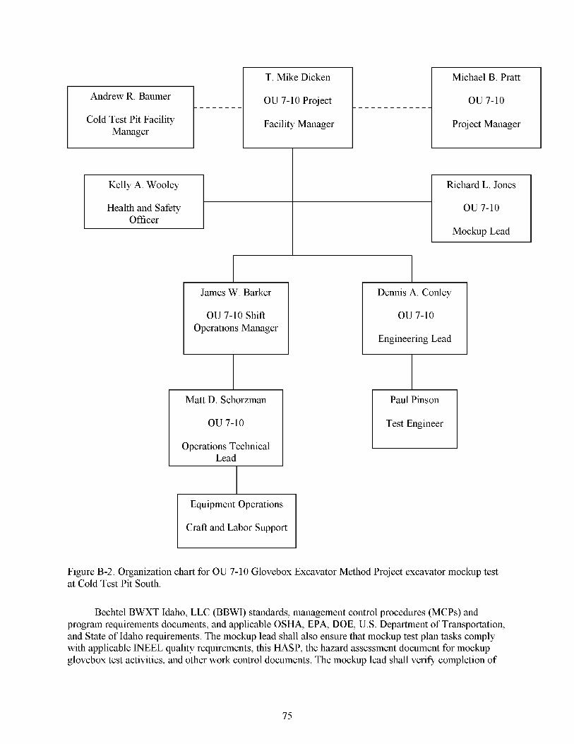
Figure B-2. Organization chart for OU 7-10 Glovebox Excavator Method Project excavator mockup test at Cold Test Pit South.
Bechtel BWXT Idaho, LLC (BBWI) standards, management control procedures (MCPs) and program requirements documents, and applicable OSHA, EPA, DOE, U. S. Department of Transportation, and State of Idaho requirements. The mockup lead shall also ensure that mockup test plan tasks comply with applicable INEEL quality requirements, this HASP, the hazard assessment document for mockup glovebox test activities, and other work control documents. The mockup lead shall verify completion of
75
mockup facility acceptance and turnover to the OU 7-10 Project Facility Manager prior to initiation of testing under the project test plan. The mockup lead reports to the OU 7-10 Project Facility Manager.
The OU 7-10 Shift Operations Manager will be responsible for all operations related to the OU 7-10 mockup. The shift operations manager will ensure all operations are performed in compliance with company policies and procedures. The shift operations manager ensures that all work is performed in compliance with the approved safety basis documents and that personnel are trained to perform the identified work in a safe, compliant manner. The OTL reports to the shift operations manager.
The Waste Area Group (WAG) 7 Cold Test Pit Facility Manager facilitates use of the INEEL Cold Test Pit South by WAG 7 projects and the OU 7-10 Glovebox Excavator Method Project for purposes of this mockup test. The facility manager is responsible for ensuring that all activities described in this appendix satisfy any special requirements governing the use of the Cold Test Pit South.
The OU 7-10 Operations Technical Lead (OTL) is the project designated field activity lead (project designee) representing the project at the test site with responsibility for the safe and successhl completion of excavation and glovebox mockup testing. The OTL manages field activities and executes the technical procedures (TPRs) and other work controls. The OTL enforces task-site control, documents activities, and may conduct the daily safety briefings at the start of each daily shift. Health and safety issues will be brought to the attention of the OTL. The OTL will report to the OU 7-10 Shift Operations Manager and will work closely with the project mockup lead and lead test engineer to complete all testing.
The OU 7- 10 Operations Engineering Lead will provide support and assistance to the test engineers for all pretest and test activities. These activities will include the test plan, test procedures, test execution, test results report, and coordination with the mockup lead. In addition, the engineering lead will assist with identifying the appropriate reviewers and approvers for all test documents. The OU 7-10 Operations Engineering Lead will serve as the point of contact with design engineering and project management for proposing any design changes resulting from mockup testing. The operations engineering lead will submit such proposed changes to the project engineer and project manager for review and approval. Such submittal will be done using the project Design Change Request form.
The test engineer serves as the primary contact concerning the design and technical execution of the glovebox mockup test plan and in the individual test procedures. The TE is responsible for ensuring that all tests are conducted as described in this test plan, that all data is collected and data sheets are complete, and that necessary resources to complete the tests are identified. The TE is ultimately responsible for determining whether test acceptance criteria are met. The TE will serve as the technical lead for all project process and equipment engineers on the test site and will work closely with the OTL to manage day-to-day test plan activities. The TE works in conjunction with the OTL to document activities, manage the work, and coordinate activities for successful completion.
The health and safety officer (HSO) assigned to the task site serves as primary contact for health and safety issues and advises the OTL and TE on all aspects of health and safety. The HSO along with everyone at the job site is authorized to stop any and all work if any operation threatens worker safety or public health or safety. The HSO is authorized to verify compliance with this HASP and the hazard assessment document for OU 7-10 mockup test activities, to conduct inspections, and to require and monitor corrective actions as appropriate.
All heavy equipment operators will be appropriately qualified for the equipment to be operated. Craft and labor support will be used to prepare the OU 7-10 mockup test plan area and as needed during the tests. Craft and labor support personnel will take direction from the OTL either directly or through their respective foreman where support is needed during mockup tests. The TE will provide test direction
76

via the OTL. When not working under mockup test plan work controls, craft and labor support will generally utilize STD-10 1, “Integrated Work Control Process,” work packages to perform assigned tasks.
B-3. RECORD-KEEPING REQUIREMENTS
No site-specific changes from the main body of this document apply to safety and health record- keeping requirements. See Section 3 of the main body of this document for the general requirements for record keeping for this project.
B-4. PERSONNEL TRAINING
Training requirements for work completed in the cold test pits (including Cold Test Pit South) are addressed in Section 4 of the main body of this document and include required general training, visitor training requirements, training verification requirements, and training documentation requirements. Additional project-specific requirements are identified in Table B- 1.
Table B-1 . Reauired OU 7-10 mockuz, z,roiect-sz,ecific training.
Training
Project-specific HASP training”
Project-site orientation briefingb
Fire extinguisher training (or equivalent)
CPR, medic first aid
Respirator training (contingency only)
OTL, STR, and
Health and Safety Officer
Yes
YesC
Yese
d
Other Field Team
Members (including samplers)
Yes
YesC
Yese
d
Non-Worker Access Support into the Zone
Contamination Access Reduction Zone Onlv
Note: Shaded fields indicate specific training is not requiredapplicable. Nonworkers will not be permitted in the exclusion zone during active mockup activities. a. Includes project-specific hazard communications, site-access and security, and decontamination and emergency response actions, as required by 29 CFR 1910.120(e). b. Orientation includes briefing of site hazards, restricted and controlled areas, emergency response actions, and personal protective equipment requirements. Personnel receiving project-site orientation briefing only are limited to the support zone and must be escorted by fully HASP-trained project supervisor or designee. c. At least one trained person should be onsite when work is takmg place. The health and safety officer will determine appropriate number of personnel requiring training. d. This training is required only if personnel are entering an area requiring respiratory protection (e.g., if action levels are exceeded, or industrial hygiene sampling shows respirators are required). e. Two medic first-aid and cardiopulmonary resuscitation (CPR) -qualified individual must be present during all OU 7-10 project cold test pit activities.
CPR-cardiopulmonary resuscitation HASP-health and safety plan OTL-operations technical lead STR-subcontract techmcal representative
77
B-5. OCCUPATIONAL MEDICAL SURVEILLANCE PROGRAM
Based on the existing site-specific information available for this project, no additional Occupational Medical Surveillance Program requirements in addition to those identified in the main body of this document apply to this section. The simulated waste being excavated contains chemical constituents described in Section B-8, but does not have the potential to trigger personnel participation in the INEEL Occupational Medical Surveillance Program. See Section 5 of the main body of this document for information about the Occupational Medical Surveillance Program requirements.
B-6. ACCIDENT PREVENTION PROGRAM
The activities addressed in this appendix will be performed under approved work control documentation prepared and authorized by the requirements in STD-10 1; MCP-3562, “Hazard Identification, Analyses, and Control of Operational Activities”; and MCP-357 1, “Independent Hazard Review.” See Section 6 of the main body of this document for information about accident prevention program requirements.
B-7. SITE CONTROL AND SECURITY
The HSO will be responsible for working with the industrial hygienist and safety engineer to establish the OU 7-10 mockup site boundaries. The HSO will establish control zones to simulate the zones to be used during the Pit 9 activities with consideration for minimizing personnel exposure to hazards at Cold Test Pit South. At a minimum, the site control zones will consist of an exclusion zone established around the excavation and soil disturbance areas. A contamination reduction zone (CRZ) will be established around the entire exclusion zone. A support zone (SZ) will be established outside of the CRZ to provide a clean area for materials staging and administrative activities. The work zones will be continually evaluated by the OTL or the HSO and adjusted as needed upon consultation with the industrial hygienist and safety engineer. Figure B-3 is a general map of possible zones that will be established at the mockup by the HSO in conjunction with input from safety and industrial hygiene.
B-7.1 Support Zone
The SZ for the OU 7-10 mockup activities will consist of the areas outside of the controlled work and restricted areas of Cold Test Pit South and will generally include the project administrative trailer, areas outside the weather structure at the pit, and other areas not otherwise marked or delineated. The SZ is established to prevent inadvertent entry into a more restrictive area of the project site and to control access to the general project site. Visitors and nonfield team members must be aware at all times of heavy equipment and vehicle traffic lanes intersecting with the SZ area.
Support facilities (e.g., project administrative trailer, vehicle parking, additional emergency equipment, extra personal protective equipment, and stored monitoring and sampling equipment) all may be located in the SZ. Visitors who do not have appropriate training to access controlled work areas, or have not received site-specific training, will be restricted to the SZ. All personnel who require entry into the CRZ or exclusion zone must complete required personal protective equipment training to wear the required personal protective equipment (Level D) to access the area (see Section 9 of the main body of this document).
78

B-7.2 Contamination Reduction Zone
The CRZ is a transition zone between the SZ and exclusion zone intended to reduce the potential for spreading contamination to the SZ. The CRZ will be arranged to provide a simulation of the intended zones in the OU 7-10 Glovebox Excavator Method Project SDA work site. The CRZ for the OU 7-10 mockup activities will consist of the areas around the exclusion zone as designated by the HSO in conjunction with input from safety and industrial hygiene.
B-7.3 Exclusion Zone
The exclusion zone will be large enough to encompass the OU 7-10 mockup activities located inside the weather structure. The exclusion zone will be arranged to provide a simulation of the intended zones at the SDA OU 7-10 Glovebox Excavator Method Project work site. The exclusion zone should consist of the designated area around the mockup of the RCS, gloveboxes, and excavator. The HSO will designate the exclusion zone based on input from safety and industrial hygiene.
B-7.4 Designated Eating and Smoking Area and Site Security
See Section 7 of the main body of this document for the requirements related to the OU 7-10 Glovebox Excavator Method Project mockup designated eating and smoking area and the site security requirements.
79

80
B-8. HAZARD EVALUATION
Section 8 of the main body of this document provides general information about the types of hazards that may be encountered while performing work at Cold Test Pit South. Applicable areas covered in Section 8 of this HASP include industrial hygiene exposure assessments, biological hazards, routes of exposure, industrial hygiene monitoring, temperature extremes, noise, fire or explosion hazards, confined spaces, excavation, material handling, powered equipment and tools, heavy equipment and machinery, Electrical and energized system hazards, personal protective equipment, and inclement weather.
B-8.1 Excavation, Surface Penetrations, and Outages
Excavation tasks will be required at Cold Test Pit South to excavate soil and simulated waste forms in the mockup construction area. No underground utilities are located in the ISG test pit area of Cold Test Pit South. A person competent in assessing excavations will be designated for all excavation tasks. The final elevation depth to the bottom of the monolith is expected to be approximately 3 to 4.5 m (10 to 15 ft) below existing grade. All excavation activities will be conducted and monitored in accordance with PRD-22, “Excavation and Surface Penetration,” and 29 CFR 1926, Subpart P, “Excavations.” Some key elements of these requirements include the following:
Excavations, the adjacent areas, and protective systems will be inspected daily by a competent person for evidence of a situation that could result in possible cave-ins, indications of failure of protective systems, hazardous atmospheres, or other hazardous conditions. The inspection will be conducted by the competent person prior to the start of work, as needed throughout the shift, and after every rainstorm or other hazard-increasing occurrence.
Sloping or benching will be constructed and maintained in accordance with the requirements set forth in 29 CFR 1926, Subpart P, Appendix B, for the soil type, as classified by the competent person. This classification of the soil deposits will be based on the results of at least one visual and at least one manual analysis. Soil classification for Cold Test Pit South soil is assumed to be Type C soil for all sloping requirements. If the excavation is not sloped on all sides, then unprotected sides or edges 1.8 m (6 ft) or more above a lower level will be protected from falling by the use of guardrail systems, safety net systems, personal fall-arrest systems, or restricted area or access locations (controlled access zones) established to prevent personnel access to the unprotected sides or edges. If the depth of the excavation exceeds 1.5 m (5 ft), personnel shall not enter the excavation area unless (1) it has been determined by a competent person to be safe with adequate slope (1.5 to l), (2) access routes have been verified by the competent person in accordance with PRD-22 and ( 3 ) a confined space evaluation has been completed and documented by the industrial hygienist in accordance with MCP-2749, “Confined Spaces.”
Other special hazards or controls: Fire extinguishers will be positioned inside the yurt structure during excavation activities as directed by the HSO and the fire protection engineer. The exhaust from the excavator used in the mockup will be passively or mechanically vented to the outside of the yurt structure. General dilution ventilation will be provided by either providing for passive air movement or by mechanically blowing fresh air into the yurt. The industrial hygienist will monitor, as appropriate, for CO buildup during equipment operation inside the yurt, and mitigative actions will be implemented based on the industrial hygienist’s measurements and recommendations.
Specific hazards associated with the OU 7-10 mockup activities, as identified for this operation, are presented in this section.
81

B-8.2 Hazards Assessment
The specific simulated waste forms buried in the ISG test pit of Cold Test Pit South are summarized in Table B-2. The simulated waste originally placed in the ISG test pit has been removed and repositioned in the OU 7-10 mockup test pit. The test pit may not contain all of the wastes listed in Tables B-2, B-3, and B-5. The hazards associated with these chemical constituents are identified in Table B-3. The project tasks, associated hazards, and appropriate mitigation are presented in Table B-4. The potential hazardous agents and the equipment available for sampling or monitoring of these agents, as determined appropriate by the industrial hygienist, are presented in Table B-5.
Table B-2. Simulated waste packages for the Cold Test Pit South in situ grouting pit. Waste Container Type Number Composition
Cardboard boxes (4 x 4 x 8 ft)
Drums 63 As listed below (55 gal) or sacks
2 Metal debris (i.e., 1/8-in. plate steel, tubing, piping, and scrap metal), concrete and asphalt chunks (6411. size), and pulverized wood. Metal 38%, concrete and asphalt 37%, and pulverized wood 25%
Cardboard 25 Combustibles @e., cloth, paper, wood, and plastic) Cardboard 13 Inorganic sludge (enough water to create a paste-like consistency;
Cardboard 6 (metal) 35 lb kitty litter) Sacks 14 Cloth and paper
390 lb soil, 40 lb dry Portland cement, and 36 lb NaN03) Organic sludge (38 gal of Texaco Regal Oil, 65 lb Micro Cell-E, and
(2 x 2 x 3 ft) (polyethylene)
B-8.3 Other Site Hazards and Inspections
Task-site personnel should look continually for potential hazards and immediately inform the OTL or HSO so that action can be taken to correct a problematic condition. The HSO and OTL will inspect the site periodically to ensure that barriers and signs are being maintained, unsafe conditions are corrected, and debris is not accumulating on the site. These inspections will be conducted in addition to daily excavation inspections.
The OTL (or designee) will perform periodic safety inspections using an appropriate checklist in accordance with MCP-3449, “Safety and Health Inspections.” In addition, targeted or required self- assessments may be performed during mockup activities in accordance with MCP-8, “Self-Assessments Process for Continuous Improvement.” All inspections and assessments will be noted in the OTL logbook. Health and safety professionals present at the task site may, at any time, recommend changes in work habits to the OTL. However, all changes that may affect the project’s written work control documents (e.g., any technical procedures, work orders, this HASP, job safety analyses, and safe work permits) must have concurrence from the appropriate project technical discipline representative onsite and have a document action request prepared on Form 4 12.1 1, “Document Management Control system (DMCS) Document Action Request (DAR),” as required.
82
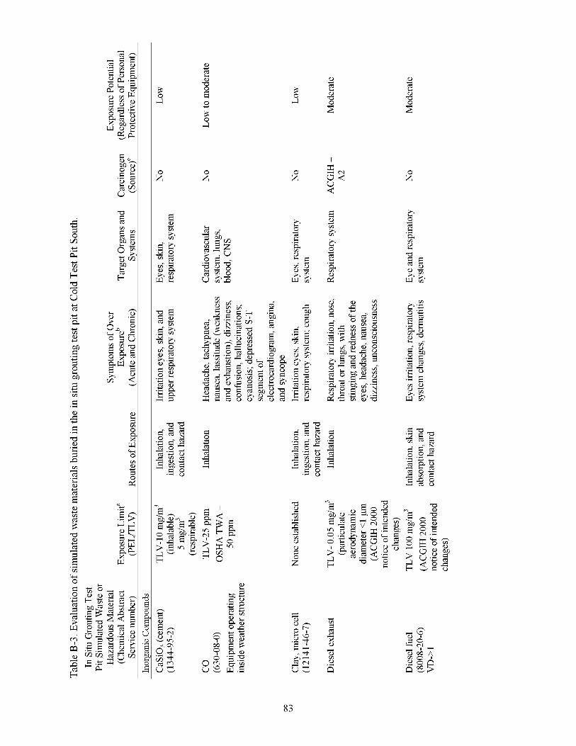
s t E W
P + .r
+
4 z L C
+ + .r
t + + E b $
t .r
E r
F
$
a
$
T
.r U
.r
f .r
'E 2
t
U c! 7
.r
+
a + 5 5 T + 7 r
E .r U
rc C $ C .r + 2 s
Fr
c: E
7
a $
a, c e E -3 0 c 3 s
z
3 s
z
c !3 m m h
83

" I
3 s 3 s 3 s
z z
c 0 cd
z z -3 -3 .3 .3 z c z c m a,
m a,
8 z 8 z
3
8
84
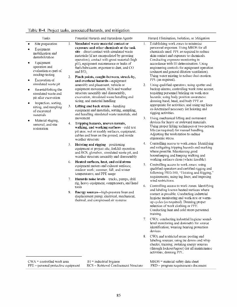
Table B-4. Project tasks, associated hazards, and mitigation.
Tasks Potential Hazards and Hazardous Agents Hazard Elimination, Isolation, or Mitigation
~
Site preparation Equipment
mobilization and demobilization Equipment
operation and evaluation as part of mockup testing
Excavation of simulated waste pit Re-establishing the
simulated waste and pit after excavation
Inspection, sorting, sizing, and sampling of excavated materials
removal, and site restoration
Material staging,
1.
2.
3.
4.
5 .
6.
7.
8.
~
CWA = controlled work area
Simulated waste material contact or exposure and other chemicals at the task s i ted i rec t contact with simulated waste materials (if not encapsulated by grouting operation), contact with grout material (high pH), equipment maintenance or leaks of fuelsllubricants, exposure to dust, and CO and NO, Pinch points, caught-between, struck-by, and overhead hazards-quipment assembly and placement, vehicle or equipment movement, RCS and weather structure assembly and disassembly, excavation, simulated waste handling and sizing, and material handling Lifting and back strain-handling equipment and materials, sorting, sampling, and handling simulated waste materials, and movement Tripping hazards, uneven terrain, walking, and working surfaces-cold test pit area, wet or muddy surfaces, equipment, cables and lines on the ground, and inside weather structure Hoisting and rigging-positioning equipment at project site, forklift operation and RCS, glovebox, simulated waste pit, and weather structure assembly and disassembly Heated surfaces, heat, and cold stress- equipment motors and exhaust surfaces; outdoor work; summer, fall, and winter temperatures; and PPE usage Hazards noise levels-trucks, pumps, drill rig, heavy equipment, compressors, and hand tools Energy sources-hgh-pressure lines and displacement pump; electrical, mechanical, thermal, and compressed air systems
M = industnal hygiene
1.
2.
3.
4.
5 .
6.
7.
8.
PPE = personal protective equipment RCS = Retrieval Confinement Structure
Establishing work zones to minimize personnel exposure. Using MSDS for all chemicals used. PPE as required to reduce skin contact and exposure to chemicals. Conducting exposure monitoring in accordance with M determination. Using engineering controls for equipment operation (exhaust and general dilution ventilation). Using water misting to reduce dust creation. PPE (as required). Using qualified operators; using spotter and backup alarms; controlling work zone access; requiring personnel briefing on work area hazards; using body position awareness; donning hand, head, and body PPE as appropriate for activities; and using tag lines as determined necessary for hoisting and rigging activities. Using mechanical lifting and movement devices for heavy or awkward materials. Using proper lifting techniques or two-person lifts (as required) for manual handling. Adjusting the workstation to reduce ergonomic stress. Controlling access to work zones. Identifying and mitigating tripping hazards and markmg where possible. Maintaining good housekeeping and keeping walkmg and working surfaces clean (where feasible). Controlling access to work zones; using qualified operators and certified rigging and following PRD-160, “Hoisting and Rigging,” requirements; using tag lines; and imposing wind restrictions. Controlling access to work zones. Identifying and labeling known heated surfaces where contact is possible. Conducting industrial hygiene monitoring and work-rest or warm- up cycles (as required). Donning proper selection of work clothmg or PPE. Conducting heat and cold stress personnel training. CWA: conducting industrial hygiene sound- level monitoring and dosimetry for source identification; wearing hearing protection devices. CWA and restricted areas: posting and labeling sources; using tie downs and whip checks; training; isolating energy sources (through lockouthagout) for all maintenance activities; donning PPE.
MSDS = material safety data sheet PRD = program requirements document
85
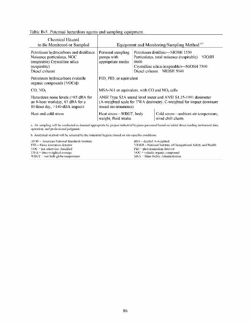
Table B-5. Potential hazardous agents and sampling equipment.
Chemical Hazard to Be Monitored or Sampled
Petroleum hydrocarbons and distillates Nuisance particulates, NOC (respirable) Crystalline silica (respirable) Diesel exhaust
Petroleum hydrocarbons (volatile organic compounds [VOCs])
CO, NO2
Hazardous noise levels (>85 &A for an 8-hour workday, 83 &A for a 10-hour day, >140-&A impact)
Heat and cold stress
Equipment and Monitoring/Sampling Method a,b
pumps with Particulates, total nuisance (respirable)-NIOSH
Crystalline silica (respirable)-NIOSH 7500 Diesel exhaust-NIOSH 5040
FID, PID, or equivalent
MSA-36 1 or equivalent, with CO and NO2 cells
ANSI Type S2A sound level meter and ANSI S1.25-1991 dosimeter (A-weighted scale for TWA dosimetry, C-weighted for impact dominant sound environments)
I Heat stress--WBGT, body weight, fluid intake
Cold stress-ambient air temperature, wind chill charts
a. Air sampling will be conducted as deemed appropriate by project industrial hygiene personnel based on initial direct reading instrument data, operation, and professional judgment.
b. Analytical method will be selected by the industrial hygiene based on site-specific conditions
ANSI = American National Standards Institute FID = flame ionization detector NOC = not otherwise classified TWA = time-weighted average WBGT = wet bulb globe temperature
dBA = decibel A-weighted NIOSH = National Institute of Occupational Safety and Health PID = photoionization detector VOC = volatile organic compound MSA = Mine Safety Administration
86

B-9. PERSONAL PROTECTIVE EQUIPMENT
Level of Personal Protective Equipment
Cold Test Pit South poses low to moderate potential hazards to all personnel from the ongoing construction, operation, and maintenance activities (Loomis et al. 1997). A description of the levels of personal protective equipment (PPE), upgrading and downgrading criteria, and PPE inspection criteria are
Category
Primary or Contingency Modifications and Comments
specified in Section 9 of the main body of this document. Visitors to the site not requiring access into the exclusion zone will require at a minimum hard hats, safety glasses with side shields, and sturdy leather boots above the ankles. Table B-6 provides the OU 7-10 mockup tasks, PPE levels, and PPE upgrade contingencies.
Table B-6. Project task-based personal protective equipment requirements and modifications. I I I
Task
All OU 7-10 Glovebox Exc,
-
Site preparation
Equipment mobilization and demobilization
Equipment operation and evaluation as part of mockup testing
Excavation of simulated waste pit
Re-establishing the simulated waste and pit after excavation
Inspection, sorting, sizing, and sampling of excavated materials
Material staging, removal, and site restoration.
rator Method Projec
Level D
Modified Level D
Level C
Activities
Primary
Upgrade contingency
Upgrade contingency
Level D PPE as defined in Section 9.2 of the main body of this document. In addition, personnel entering the exclusion zone will wear safety-toed boots. Modifications for specific hand protection for material handling and sampling tasks will be defined by the HSO.
Upgrading to modified Level D (protective clothing, Tyvek coveralls or equivalent) may be required if action levels are exceeded or contact with simulated waste material cannot be avoided (prolonged and extensive skin contact).
If airborne contaminants increase to concentrations above established action limits, Level C hll-face air-purifying respiratory protection will be worn in conjunction with chemical protective clothing (cartridge to be selected by project IH based on airborne hazard).
HSO = health and safety officer IH = industrial hygienist PPE = personal protective equipment
87
B-10. DECONTAMINATION PROCEDURES
The OU 7-10 mockup activities are being conducted at Cold Test Pit South over the ISG test pit (with simulated waste forms) with no hazardous or radiological constituents. Though some of the raw materials used in the simulated waste mixture could present a potential inhalation or skin hazard, the use of engineering and administrative controls should minimize personnel exposure. Therefore, hazardous or radiological decontamination is not required. If simulated waste materials are encountered at levels that present a contact or airborne release hazard to personnel, implementation of additional engineering controls, or some wetting or limited decontamination procedures, may be required to mitigate the potential hazards. In addition, equipment may be cleaned (i.e., decontaminated) at the end of the project using gross mechanical techniques, wiping, or steam cleaning, as required.
B-I 0.1 Contamination Control and Prevention
If contamination is encountered during OU 7- 10 mockup activities, additional wetting or engineering controls will be used to mitigate contact or airborne hazards. Contamination control and prevention procedures will be implemented to minimize personnel contact with contaminated surfaces if such surfaces are encountered and contacted. The following contamination control and prevention measures will be employed if contamination is encountered:
Identify potential sources of contamination and design containment, isolation, and engineering controls to eliminate or mitigate any potential for contact or release of contaminants
Limit the number of personnel, equipment, and materials that enter the contaminated area
Implement immediate decontamination procedures to prevent the spread of contamination (if contamination is found on the outer surfaces of equipment)
Use only the established control entry and exit point from the contaminated area to minimize the potential for cross-contamination and expedite contamination control surveys
Wear disposable outer garments and use disposable equipment (where possible).
B-I 0.2 Personnel and Equipment Decontamination
Decontamination procedures for personnel and equipment during OU 7- 10 mockup activities are not anticipated to be required beyond normal PPE changeout and equipment cleaning, respectively. If waste contact cannot be avoided (e.g., excessive contact from prolonged periods that may cause skin irritation or drying or dermatitis), then additional engineering controls, in combination with PPE upgrades, may be necessary to control the contact hazard. Equipment will be decontaminated based on the source of contamination.
B-I 0.3 Modified Level D Personal Protective Equipment Doffing and Decontamination (If Required)
If required to be worn during OU 7-10 mockup activities, modified Level D (see Section 9 of the main body of this document) protective clothing (e.g., disposable coveralls) will be doffed following standard removal techniques (rolling outside surface inward and down) and will constitute the initial decontamination step. All PPE will be placed in the appropriately labeled containers. Cloth coveralls may be reused as long as they remain serviceable, according to an industrial hygienist and safety professional judgment call.
88
B-10.4 Level C Personal Protective Equipment Doffing and Decontamination (If Required)
If respiratory protection is worn during OU 7-10 mockup activities in conjunction with protective clothing (e.g., Level C PPE [see Section 9 of the main body of this document]), then the modified Level D sequence will be followed with one additional step. For that additional step (following protective clothing doffing), respirators will be removed and placed in a separate container.
B-10.5 Site Sanitation and Waste Minimization
During OU 7-10 mockup activities, site personnel will use the portable toilet facilities provided in the Cold Test Pit South or restroom facilities inside the RWMC area. Potable water and soap, or hand and face sanitary wipes, will be available within the administrative trailer or the RWMC facility for personnel to wash their hands and face upon exiting the work area.
Waste materials will not be allowed to accumulate at the project task sites. Appropriately labeled containers for industrial waste and CERCLA waste will be maintained at the project site. Personnel should make every attempt to minimize waste through the judicious use of consumable materials. All site personnel are expected to make good housekeeping a priority at the job site.
B-I 1. EMERGENCY RESPONSE PLAN FOR COLD TEST PIT SOUTH
Section 11 of the main body of this document defines the responsibilities of personnel working at the cold test pits (including Cold Test Pit South) and the INEEL Emergency Response Organization by providing an emergency response plan for guidance in responding to abnormal events during activities at the pits. Section 11 of the main body of this document is applicable to the OU 7-10 mockup activities and will be implemented as applicable.
B-I 1.1 NOTIFICATIONS
As directed by the office of the Secretary of Energy, the RWMC area director will be responsible for immediately notifying the DOE and local agencies off-Site of all significant abnormal events that occur at the cold test pits. This duty will be in addition to the notification requirements established in INEEL procedures for events that are categorized as emergencies or unusual occurrences. For this reason, the OU 7-10 mockup project operations technical lead will immediately report all abnormal events that occur on the site to the RWMC shift supervisor and to the WCC. The WCC will, in turn, notify the appropriate INEEL emergency response resources and other INEEL facilities. The RWMC shift supervisor and the WCC share the responsibility for notifying the RWMC facility manager, emergency coordinator, and area director, as appropriate. The operations technical lead may make additional notifications (as listed in Section B-1 1.2) at the discretion of the project supervision.
The emergency coordinator will be the single point of contact between the project and the INEEL ERO and off-Site people or agencies. The emergency coordinator will make all off-Site notifications. The OU 7-10 Mockup project notification responsibilities are listed in Table B-7.
89
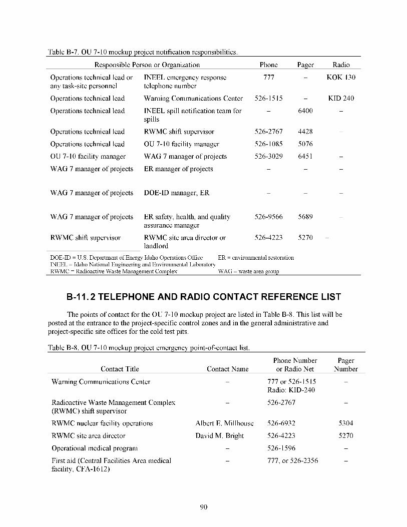
Table B-7. OU 7-10 mockup project notification responsibilities.
Responsible Person or Organization Phone Pager Radio
Operations technical lead or any task-site personnel
Operations technical lead
Operations technical lead
Operations technical lead
Operations technical lead
OU 7- 10 facility manager
WAG 7 manager of projects
WAG 7 manager of projects
WAG 7 manager of projects
RWMC shift supervisor
INEEL emergency response 777 - KOK 130 telephone number
Warning Communications Center 526- 15 15 - KID 240
spills INEEL spill notification team for - 6400 -
RWMC shift supervisor 526-2767 4428 -
WAG 7 manager of projects 526-3029 645 1 -
ER manager of projects - - -
OU 7- 10 facility manager 526-1085 5076
DOE-ID manager, ER - - -
ER safety, health, and quality 526-9566 5689 -
assurance manager
RWMC site area director or 526-4223 5270 -
landlord ~
DOE-ID = U.S. Department of Energy Idaho Operations Office WEEL = Idaho National Engineering and Environmental Laboratory RWMC = Radioactive Waste Management Complex
ER = environmental restoration
WAG - waste area group
B-I 1.2 TELEPHONE AND RADIO CONTACT REFERENCE LIST
The points of contact for the OU 7-10 mockup project are listed in Table B-8. This list will be posted at the entrance to the project-specific control zones and in the general administrative and project-specific site offices for the cold test pits.
Table B-8. OU 7-10 mockup project emergency point-of-contact list.
Phone Number Pager Contact Title Contact Name or Radio Net Number
Warning Communications Center - 777 or 526-1515 -
Radioactive Waste Management Complex - 526-2767 -
Radio: KID-240
(RWMC) shift supervisor
RWMC nuclear facility operations Albert E. Millhouse 526-6932 5304
RWMC site area director David M. Bright 526-4223 5270 Operational medical program - 526- 1596 -
First aid (Central Facilities Area medical - 777, or 526-2356 -
facility, CFA- 16 12)
90
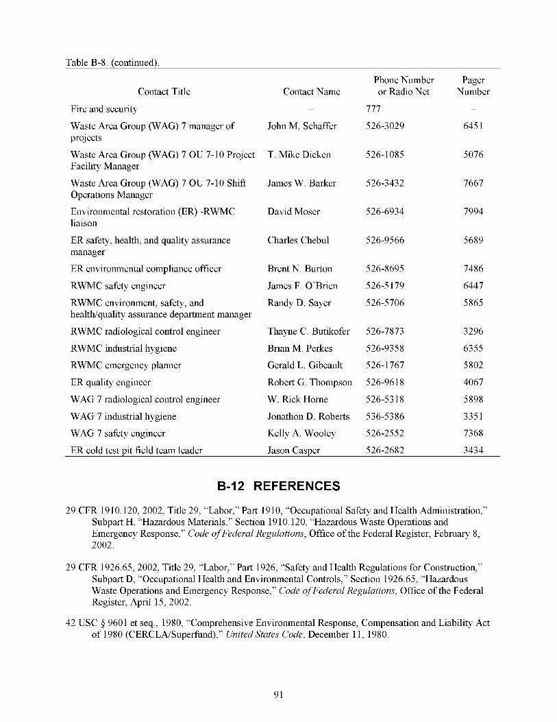
Table B-8. (continued).
Contact Title
Fire and security
Waste Area Group (WAG) 7 manager of projects
Waste Area Group (WAG) 7 OU 7-10 Project Facility Manager
Waste Area Group (WAG) 7 OU 7-10 Shift Operations Manager
Environmental restoration (ER) -RWMC liaison
ER safety, health, and quality assurance manager
ER environmental compliance officer
RWMC safety engineer
RWMC environment, safety, and healtWquality assurance department manager
RWMC radiological control engineer
RWMC industrial hygiene
RWMC emergency planner
ER quality engineer
WAG 7 radiological control engineer
Contact Name -
John M. Schaffer
T. Mike Dicken
James W. Barker
David Moser
Charles Chebul
Brent N. Burton
James F. O’Brien
Randy D. Sayer
Thayne C. Butikofer
Brian M. Perkes
Gerald L. Gibeault
Robert G. Thompson
W. &ck Home
Phone Number or Radio Net
777
526-3029
526-1085
526-3432
526-6934
526-9566
526-8695
526-5 179
526-5706
526-7873
526-9358
526-1767
526-96 18
526-53 18
Pager Number
645 1
5076
7667
7994
5689
7486
6447
5865
3296
6355
5802
4067
5898
WAG 7 industrial hygiene Jonathon D. Roberts 536-5386 335 1
WAG 7 safety engineer Kelly A. Wooley 526-2552 7368
ER cold test pit field team leader Jason Casper 526-2682 3434
B-12 REFERENCES
29 CFR 19 10.120, 2002, Title 29, “Labor,” Part 1910, “Occupational Safety and Health Administration,” Subpart H, “Hazardous Materials,” Section 19 10.120, “Hazardous Waste Operations and Emergency Response,” Code of Federal Regulations, Office of the Federal Register, February 8, 2002.
29 CFR 1926.65, 2002, Title 29, “Labor,” Part 1926, “Safety and Health Regulations for Construction,” Subpart D, “Occupational Health and Environmental Controls,” Section 1926.65, “Hazardous Waste Operations and Emergency Response,” Code of Federal Regulations, Office of the Federal Register, April 15, 2002.
42 USC 9 9601 et seq., 1980, “Comprehensive Environmental Response, Compensation and Liability Act of 1980 (CERCLAKuperhnd),” United States Code, December 11, 1980.
91

ACGIH, 200 1, Threshold Limit Values for Chemical Substances and Physical Agents, American Conference of Governmental Industrial Hygienists.
DOE, 2002, Agreement to Resolve Disputes, the State of Idaho, United States Environmental Protection Agency, United States Department ofEnergy, U.S. Department of Energy, State of Idaho, U.S. Environmental Protection Agency, April 18, 2002.
DOE-ID, 1998, Explanation of Signzjcant Dlfferences for the Pit 9 Interim Action Record ofDecision at the Radioactive Waste Management Complex at the Idaho National Engineering and Environmental Laboratory, U. S. Department of Energy, Idaho Field Office; U. S. Environmental Protection Agency, Region 10; Idaho Department of Health and Welfare, August 1998.
DOE-ID, 1993, Record of Decision: Declaration of Pit 9 at the Radioactive Waste Management Complex Subsurface Disposal Area at the Idaho National Engineering Laboratory, Idaho Falls, Idaho, Administrative Record No. 5569, U.S. Department of Energy Idaho Operations Office; U.S. Environmental Protection Agency Region 10; and State of Idaho Department of Health and Welfare, October 1, 1993.
DOE-ID, 199 1, Federal Facility Agreement and Consent Order for the Idaho National Engineering Laboratory, U. S. Department of Energy, Idaho Field Office; U. S. Environmental Protection Agency, Region 10; Idaho Department of Health and Welfare, December 4, 199 1.
Form 412.11,2001, “Document Management Control Systems (DMCS) Document Action Request (DAR),” Rev. 6, August 9, 2001.
INEEL, 2002a, OU 7-1 0 Glovebox Excavator Method Project Conceptual Design Report for Critical Decision 1, INEEL/EXT-0 1-0 15 12, Idaho National Engineering and Environmental Laboratory, Bechtel BWXT, LLC, Idaho Falls, Idaho, January 2002.
INEEL, 2002b, OU 7-1 0 Glovebox Excavator Method Project Execution Plan for Critical Decision 1 ~
INEEL/EXT-0 1-0 15 13, PLN- 10 16, Rev. 1, Idaho National Engineering and Environmental Laboratory, Bechtel BWXT, LLC, Idaho Falls, Idaho, June 2002.
INEEL, 2001, Waste Area Group 7Analysis of OU 7-10 Stage IIModzjcations, INEEL/EXT-O1-01105, Idaho National Engineering Laboratory, Bechtel BWXT Idaho, LLC, Idaho Falls, Idaho, October 200 1.
Loomis, Guy G., James J. Jessmore, and Jerry R. Weidner, 2001, Implementation Test and Field Test Plan for the Operable Unit 7-1 3/14 In Situ Grouting Treatability Study, INEEL/EXT-2000-00449, Rev. 1, Idaho National Engineering and Environmental Laboratory, Bechtel BWXT Idaho, LLC, Idaho Falls, Idaho.
MCP-8, 2002, “Self-Assessments and Continuous Improvements,” Rev. 6, January 23,2002
MCP-2749, 2002, “Confined Spaces,” Rev. 4, April 17,2002
MCP-3449, 200 1, “Safety and Health Inspections,” Rev. 2, June 25, 200 1.
MCP-3571, 2002, “Independent Hazard Review,” Rev. 4, April 23, 2002.
NIOSH 0660, 1998, “NIOSH Analytical Method 0660,” NIOSHManual ofAnalytica1 Methods, 4th ed., U.S. Department of Health and Human Services, Public Health Service, Centers for Disease Control and Prevention, National Institute for Occupational Safety and Health, January 1998.
92

NIOSH 1550, 1998, “NIOSH Analytical Method 1550,” NIOSHManual ofAnalytica1 Methods, 4th ed., U.S. Department of Health and Human Services, Public Health Service, Centers for Disease Control and Prevention, National Institute for Occupational Safety and Health, January 1998.
NIOSH 5040, 1998, “NIOSH Analytical Method 5040,” NIOSHManual ofAnalytica1 Methods, 4th ed., U.S. Department of Health and Human Services, Public Health Service, Centers for Disease Control and Prevention, National Institute for Occupational Safety and Health, January 1998.
NIOSH 7500, 1998, “NIOSH Analytical Method 7500,” NIOSHManual ofAnalytica1 Methods, 4th ed., U.S. Department of Health and Human Services, Public Health Service, Centers for Disease Control and Prevention, National Institute for Occupational Safety and Health, January 1998.
PRD-22, 1999, “Excavation and Surface Penetrations,” Rev. 1, Manual14A-Occupational Safety and Fire Protection, May 3 1, 1999.
PRD-160, 2000, “Hoisting and Egging,” Rev. 2, Manual14A, Safety and Health-Occupational Safety and Fire Protection, Safety and Health Department, April 6, 2000.
STD-101,2001, “Integrated Work Control Process,” Rev. 12, Operations, September 19, 2001.
93

94