operator's manual - kubota.com.au · precautions in case of overheat ... excavator operation...
TRANSCRIPT
1BAAEALAP0090.eps
1BAAEALAP0100
1BAAEALAP01001BAAEALAP0090
OPERATOR'S MANUAL
English (Australia)Code No. RC788-8131-5
MODEL U35-4
U35-
4
PRINTED IN JAPAN © KUBOTA Corporation 2013
READ AND SAVE THIS MANUAL

U35-4AW . A . 11 - 13 . 1 . AK
LIST OF ABBREVIATIONAbbreviations Description
American Petroleum Institute
American Society for Testing and Materials, USA
Committee for European Construction Equipment
German Institute for Standards, Federal Republic of Germany
European Standard
Occupational Safety and Health Administration
"Front" means the front view towards the boom and dozer
High speed
International Standardization Organization
Japanese Industrial Standard
Volume (Liter)
Liter per minute
Low speed
Military Standards
Operator Protective Guards of Top Guard Level I
Revolutions Per Minute
Roll-Over Protective Structures
Society of Automotive Engineers, USA
Two Pattern Selection System
Auto Idle
API
ASTM
CECE
DIN
EN
OSHA
FRONT
Hi
ISO
JIS
L
L/min
Lo
MIL
OPG(Top Guard Level I)
rpm
ROPS
SAE
TPSS
AI

GENERAL SYMBOLSThe instruments and operation elements have been marked with a series of symbols in order to simplify the operation of excavator. These symbols are listed below with the respective descriptions.
Safety alert Symbol
Warning lamp ''Fuel level too low''
System lamp
Warning lamp ''Engine Oil pressure''
Warning lamp ''Battery charge''
Warning lamp ''Auto Idle (AI) Lamp''
Indicator lamp ''Glow''
Working light switch
Horn
Wiper/Washer switch
Diesel
Hydraulic fluid
Gear oil
Grease
Fast
Slow
Excavator - Overhead movement toward the front
Excavator - Overhead movement toward the rear
Boom up
Boom down
Arm up
Arm crowd
Bucket crowd
Bucket dump
Boom swing (left)
Boom swing (Right)
Dozer raise
Dozer lower
Operation direction of control lever
Operation direction of control lever
Read operator's manual
Engine stop control lamp

FOREWORD
3SAFETY FIRST
IMPORTANT :
NOTE :
3 DANGER :
3 WARNING :
3 CAUTION :
Indicates an imminently hazardous situation which, if not avoided, will result in death or serious injury.
Indicates a potentially hazardous situation which, if not avoided, could result in death or serious injury.
Indicates a potentially hazardous situation which, if not avoided, could result in minor or moderate injury.
Indicates that equipment or property damage could result if instructions are not followed.
Gives helpful information.
You are now the proud owner of a KUBOTA Excavator. This excavator is a product of KUBOTA quality engineering and manufacturing. It is made of fine materials and under a rigid quality control system. It will give you long, satisfactory service. To obtain the best use of your excavator, please read this manual carefully. It will help you become familiar with the operation of the excavator and contains many helpful hints about excavator maintenance. It is KUBOTA's policy to utilize as quickly as possible every advance in our research. The immediate use of new techniques in the manufacture of products may cause some small parts of this manual to be outdated. KUBOTA distributors and dealers will have the most up-to-date information. Please do not hesitate to consult with them.
This symbol, the industry's ''Safety Alert Symbol'', is used throughout this manual and on labels on the machine itself to warn of the possibility of personal injury. Read these instructions carefully. It is essential that you read the instructions and safety regulations before you attempt to assemble or use this unit.

CONTENTS
SAFE OPERATION ............................................................................................ -1DEALER SERVICE...................................................................................................... 1
TECHNICAL DATA...................................................................................................... 3
DESCRIPTION OF MACHINE PARTS........................................................................ 4
INSTRUMENT PANEL AND CONTROL ELEMENTS................................................. 5
CHECKS BEFORE START ......................................................................................... 7DAILY CHECKS....................................................................................................... 7CHECKING THE DEVICES ..................................................................................... 7
Starter Switch ...................................................................................................................7Display Selector Switch ....................................................................................................8LCD for Normal Operation ................................................................................................8Warning Lamp ................................................................................................................11LCD for Warning.............................................................................................................11Setting the Clock.............................................................................................................13Reordering the year/month/day and Changing the AM/PM System to the 24-hour One 14Log Record .....................................................................................................................15Periodic Check................................................................................................................16If All the Check Points are not Displayed at a Glance on a Single Screen.....................16When the Check-up is Completed..................................................................................18Horn Switch ....................................................................................................................18Light Switch ....................................................................................................................18AUX Port Enable Switch .................................................................................................18Auto Idle Control Switch .................................................................................................19Throttle Potentiometer ....................................................................................................19Travel Speed Switch.......................................................................................................19
CAB TYPE MACHINES ......................................................................................... 20Wiper/Washer Switch .....................................................................................................20Interior Lamp...................................................................................................................20Opening/Closing of CAB Door ........................................................................................21Opening/Closing of Front CAB Window..........................................................................21Opening/Closing of Side CAB Window...........................................................................21Emergency Hammer.......................................................................................................21
AIR CONDITIONER............................................................................................... 22Air Flow...........................................................................................................................22Air Control Vent ..............................................................................................................22Control Panel ..................................................................................................................23Operation........................................................................................................................23
HANDLING THE SAFETY DEVICES..................................................................... 23Pilot Control Lock Lever..................................................................................................23
OPERATION OF THE ENGINE................................................................................. 24STARTING THE ENGINE...................................................................................... 24STARTING THE ENGINE UNDER COLD CONDITIONS...................................... 25STARTING WITH AN AUXILIARY BATTERY ....................................................... 26
Observe Following Guidelines when Starting with an Auxiliary Battery..........................26
CONTENTS
CHECK POINTS AFTER STARTING THE ENGINE ............................................. 26STOPPING THE ENGINE...................................................................................... 27
Engine Stop Button.........................................................................................................27Precautions in case of Overheat.....................................................................................27
EXCAVATOR OPERATION ...................................................................................... 28RUNNING-IN OF THE NEW EXCAVATOR........................................................... 28
Do not Work with Full Engine Rpm's or Full Loads during the First 50 Working Hours..28Oil Change in the Run-in Stage......................................................................................28Adjusting the Operator's Seat.........................................................................................28Seat Belt .........................................................................................................................29
STARTING............................................................................................................. 29Pilot Control Lock Lever..................................................................................................29
DRIVING ................................................................................................................ 30Drive Levers (Right,Left).................................................................................................31
TURNS................................................................................................................... 31Pivot Turn .......................................................................................................................31Spin Turn ........................................................................................................................32
UP AND DOWNHILL DRIVING.............................................................................. 33PARKING ON A SLOPE ........................................................................................ 33OPERATION OF THE DOZER .............................................................................. 33TWO PATTERN SELECTION SYSTEM (TPSS) ................................................... 34
Pattern Change...............................................................................................................34OPERATION OF THE BOOM................................................................................ 35OPERATION OF THE ARM................................................................................... 35OPERATION OF THE BUCKET ............................................................................ 36UNIT SWING AND BOOM SWING OPERATION.................................................. 36
Unit Swing Operation......................................................................................................36Boom Swing Operation...................................................................................................36
AUXILIARY PORT OPERATION ........................................................................... 37Selecting the Action Modes ............................................................................................37AUX Port Handling Procedure........................................................................................38Setting the Maximum Flow Volume ................................................................................40
HOW TO RELEASE PRESSURE TRAPPED IN THE HYDRAULIC SYSTEM...... 451-way or 2-way CIRCUIT SELECTION VALVE OPERATION............................... 46AUTO IDLE (AI) OPERATION ............................................................................... 47IMPORTANT INFORMATION ON EXCAVATOR OPERATION............................ 48
TRANSPORTING THE EXCAVATOR ON A VEHICLE............................................. 49
LIFTING OF THE EXCAVATOR................................................................................ 51
MAINTENANCE......................................................................................................... 53MAINTENANCE INTERVALS................................................................................ 53OPENING AND CLOSING OF COVERS............................................................... 56
Opening/Closing of the Engine Hood .............................................................................56Opening/Closing of the Side Cover ................................................................................56Where to store the Tool ..................................................................................................57Cup Holder......................................................................................................................57Where to store the Grease Gun......................................................................................57Where to keep Operator's Manual..................................................................................57
DAILY CHECKS..................................................................................................... 58

CONTENTS
Checking Coolant Level..................................................................................................58Checking Fuel Level .......................................................................................................58Checking Engine Oil Level..............................................................................................59Checking Hydraulic Oil Level..........................................................................................59Checking V-belt ..............................................................................................................60Checking Radiator and Oil Cooler ..................................................................................60Checking Washer Liquid.................................................................................................61Checking and Cleaning Engine and Electrical Wiring.....................................................61Washing Whole Machine................................................................................................61Greasing Front Attachments (without Bucket Pin and Boom Swing Fulcrum)................61Greasing Bucket Pin.......................................................................................................62Greasing Boom Swing Fulcrum......................................................................................62
REGULAR CHECKS AND MAINTENANCE WORK ................................................. 63EVERY 50 SERVICE HOURS ............................................................................... 63
Draining the Water from the Fuel Tank...........................................................................63Draining Water Separator ...............................................................................................63Checking Battery Condition ............................................................................................64Greasing Swing Bearing Teeth.......................................................................................65
EVERY 200 SERVICE HOURS ............................................................................. 66Adjusting V-belt Tension.................................................................................................66Checking Radiator Hoses and Clamps...........................................................................67Grease Swing Ball Bearing.............................................................................................67Inspection and Cleaning Air Filter Element.....................................................................67Air Filter Maintenance.....................................................................................................68Checking Fuel Line and Intake Air Line ..........................................................................68
AIR CONDITIONER............................................................................................... 69Cleaning Air Filter ...........................................................................................................69Checking Air-Conditioner Condenser .............................................................................69
EVERY 250 SERVICE HOURS ............................................................................. 70Changing Engine Oil (First Engine Oil Change after 50 Service Hours) ........................70Replacing Engine Oil Filter Cartridge (First Engine Oil Filter Change after 50 Service Hours) .............................................................................................................................70
EVERY 500 SERVICE HOURS ............................................................................. 71Drive unit Oil Change(First Oil Change of the 50 hours) ................................................71Replacing Fuel Filter Cartridge .......................................................................................71Replacing Hydraulic Return Filter Element (First replacement after 250 service hours) 72Replacing Breather Filter ................................................................................................72Replacing Fan Belt .........................................................................................................72
EVERY 1000 SERVICE HOURS ........................................................................... 72Replacing the Hydraulic Pilot Filter Element...................................................................72Hydraulic Oil Change (Including Replacing of the Suction Filter in the Hydraulic Tank) 73Hydraulic Oil Check with Hydraulic Hammers ................................................................74
EVERY 1000 SERVICE HOURS OR ONCE A YEAR ........................................... 74Replacing Air Filter Element ...........................................................................................74
EVERY 1500 SERVICE HOURS ........................................................................... 74Checking Fuel Injection Nozzle (Injection Pressure) ......................................................74
EVERY 2000 SERVICE HOURS ........................................................................... 74Changing Front Idler and Track Roller Oil ......................................................................74Checking the Alternator and Starter Motor .....................................................................74
EVERY 3000 SERVICE HOURS ........................................................................... 74Checking Injection Pump................................................................................................74
CONTENTS
ANNUAL SERVICING............................................................................................ 75Electrical Wiring and Fuses ............................................................................................75Checking the Electrical Circuit ........................................................................................75Checking Air-Conditioner Pipes and Hoses....................................................................75
BIENNIAL SERVICING.......................................................................................... 75Replacing Air-Conditioner Pipes and Hoses...................................................................75Replacement of Radiator Hoses and Hose Clamps .......................................................75Changing Radiator Coolant ............................................................................................75Replacing Fuel Hoses and Hose Clamps.......................................................................76Replacing Intake Air line .................................................................................................77
SERVICING AS REQUIRED.................................................................................. 77Checking Amount of Refrigerant (gas) ...........................................................................77
OTHER ADJUSTMENTS AND REPLACEMENTS.................................................... 78PURGING OF THE FUEL SYSTEM ...................................................................... 78ADJUSTMENT OF TRACKS ................................................................................. 78
Special Information when Using Rubber Tracks.............................................................79CHANGING THE BUCKET.................................................................................... 80FUSES ................................................................................................................... 80
Replacing Fuses.............................................................................................................80Fuse Capacities and Circuits ..........................................................................................81Auxiliary Electric .............................................................................................................82Slow Blow Fuse ..............................................................................................................82
TROUBLESHOOTING............................................................................................... 83
OPERATION UNDER COLD WEATHER CONDITIONS .......................................... 85PREPARATION FOR OPERATION IN COLD WEATHER.................................... 85PROCEDURE AFTER COMPLETING WORK ...................................................... 85
LONG STORAGE...................................................................................................... 86
RECOMMENDED OILS............................................................................................. 88
APPENDICES............................................................................................................ 90MAIN DIMENSIONS .............................................................................................. 90
LIFTING CAPACITY.................................................................................................. 91
LIST OF SCREENS................................................................................................... 94LIST OF NORMAL SCREENS............................................................................... 94NAVIGATION LIST OF SCREENS........................................................................ 95
-1SAFE OPERATION
SAFE OPERATION
Careful operation is your best insurance against anaccident.Read and understand this manual carefully, beforeoperating the excavator.Every user, however experienced, should carefully readand understand this manual and those of the attachmentsand accessories before operating the excavator. Theowner is obliged to inform all operators of theseinstructions in detail.Keep this manual in the storage location. (See "Where tokeep Operator's Manual" in "MAINTENANCE" section.)1. Know your equipment and its limitations. Read andunderstand this entire manual before attempting tostart and operate the excavator.
2. Pay special attention to and obey the danger, warningand caution labels on the machine.
3. For your safety, a ROPS/OPG (Top Guard Level I)with a seat belt is installed by KUBOTA.A ROPS: Roll-Over Protective StructureA OPG (Top Guard Level I): Operator Protective
Guards of Top Guard Level IOPG (Top Guard Level I) in accordance withISO10262 is equivalent in definition to FOPS (FallingObject Protective Structure).Always use the seat belt when the machine isequipped with a ROPS/OPG (Top Guard Level I) asthis combination will reduce the risk of serious injury ordeath, should the excavator be upset or falling objectsoccur.Do not modify any structural members of the ROPS/OPG (Top Guard Level I) by welding, drilling, bending,grinding or cutting, as this may weaken the structure.If any component is damaged, replace it. Do notattempt repairs. If the ROPS/OPG (Top Guard Level I)is loosened or removed for any reason, make sure allparts are reinstalled correctly. Tighten mounting boltsto proper torque.
4. ROPS meets requirements of ISO 3471.OPG (Top Guard Level I) meets requirements ofOSHA 1926 1003/ISO 10262.
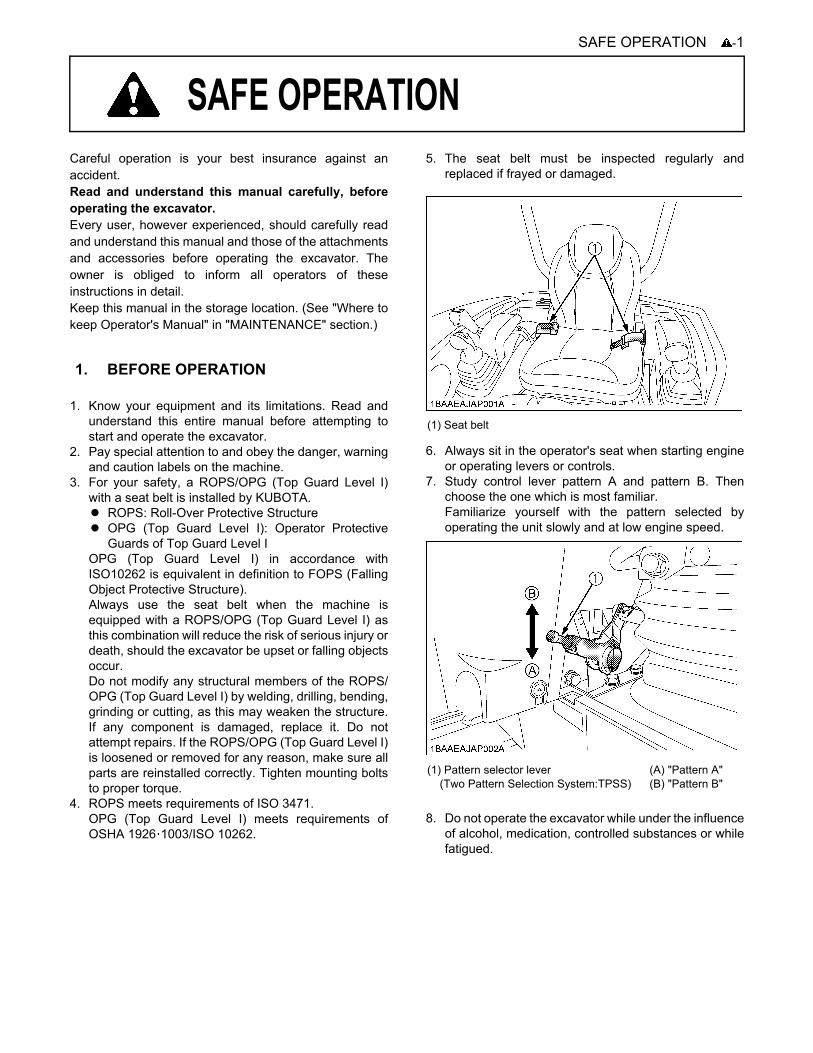
5. The seat belt must be inspected regularly andreplaced if frayed or damaged.
6. Always sit in the operator's seat when starting engineor operating levers or controls.
7. Study control lever pattern A and pattern B. Thenchoose the one which is most familiar.Familiarize yourself with the pattern selected byoperating the unit slowly and at low engine speed.
8. Do not operate the excavator while under the influenceof alcohol, medication, controlled substances or whilefatigued.
1. BEFORE OPERATION
(1) Seat belt
(1) Pattern selector lever (Two Pattern Selection System:TPSS)
(A) "Pattern A"(B) "Pattern B"

SAFE OPERATION-2
9. Check the surroundings carefully before using theexcavator or when attachments are being attached.
A Pay attention to the overhead clearance with electricwires.
A Check for pipes and buried cables before digging. Useyour local utility service to check for such items (ifavailable).
A Check for hidden holes, obstacles, soft underground,and overhangs.
A Do not allow any persons within the working range ofthe excavator during operation.
10.Do not allow anyone to use the excavator until theyhave been advised of the work to be performed andthey have indicated that they have read andunderstood the operator's manual.
11.Do not wear baggy, torn or oversized clothing whenworking with the excavator as such clothing can getcaught in rotating parts or control elements which cancause accidents or injuries. Wear adequate safetyclothing, e.g. safety helmet, safety shoes, eyeprotection, ear protection, working gloves, etc., asnecessary and as prescribed by law or statutes.
12.Do not allow passengers to ride on any part of theexcavator at any time. The operator must remain in theexcavator seat during operation.
13.Check levers, pedals and all mechanical parts forcorrect adjustment and wear. Replace worn ordamaged parts immediately. Check nuts and boltsregularly for correct torque.
14.Keep your excavator clean. Heavy soiling, grease,dust and grass can cause fires, accidents or injuries.
15.Use only KUBOTA authorized attachments.16.Before starting the excavator, be absolutely sure that
the excavator has been filled with fuel, lubricated,greased and undergone all necessary maintenance.
17.Do not modify the excavator, as such could lead tounforeseen safety problems.
18.Do not operate a hydraulic hammer on anything that isabove the operator's seat level as objects may fall intothe operator station.
19.Make sure attachments, particularly those utilizingquick attach systems, are securely mounted.
20. Install protective guards on the excavator whenworking in areas where objects may fall or be thrown.The top guard and front guard are available for thismachine. Consult your KUBOTA dealer for details.
(1) Helmet(2) Clothing fit for work(3) Tight seams(4) Good grip footwear(5) Well fitting cuffs(6) Working gloves
(7) Soft hat(8) Towel(9) Baggy trousers(10) Loose cuffs of the shirt(11) Baggy shirt(12) Sandals or open-toed shoes
-3SAFE OPERATION
Operator safety is a priority. Safe operation, specificallywith respect to overturning hazards, entails understandingthe equipment and environmental conditions at the time ofuse. Some prohibited uses which can affect overturninghazards include traveling and turning with implementsand loads carried too high etc. This manual sets forthsome of the obvious risks, but the list is not, and cannotbe, exhaustive. It is the operator's responsibility to be alertfor any equipment or environmental condition that couldcompromise safe operation.
C Starting
1. Mount and dismount the machine safely. Always facethe machine. Always use handrails and availablesteps and keep yourself well balanced. Do not grab orhold any of the control levers and switches. Do notjump on or off the machine, whether stationary or inmotion.
2. Start and control the excavator only from theoperator's seat. The driver should not lean out of hisseat when the engine is running.
3. Before starting the engine, make sure that the locklevers are in the "LOCKED" position and all controllevers and pedals are in their neutral positions and theseat belt is fastened correctly.Before starting the engine, make sure that the controllevers, travel lever, pedals and other control elementsare not stuck and can be moved smoothly.If stuck, for example, a lever may fail to return, possiblyputting you in danger.If anything wrong is found, immediately pinpoint thecause and correct it.
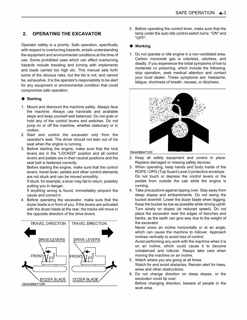
4. Before operating the excavator, make sure that thedozer blade is in front of you. If the levers are activatedwith the dozer blade at the rear, the tracks will move inthe opposite direction of the drive levers.
5. Before operating the control lever, make sure that thelamp under the auto idle control switch turns "ON" and"OFF".
C Working
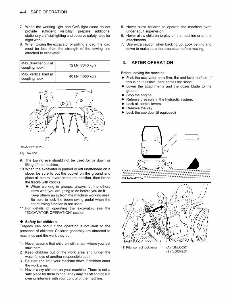
1. Do not operate or idle engine in a non-ventilated area.Carbon monoxide gas is colorless, odorless, anddeadly. If you experience the initial symptoms of low tomoderate co poisoning, which include the following,stop operation, seek medical attention and contactyour local dealer. These symptoms are: headache,fatigue, shortness of breath, nausea, or dizziness.
2. Keep all safety equipment and covers in place.Replace damaged or missing safety devices.
3. When operating, keep hands and body inside of theROPS / OPG (Top Guard Level I) protective envelope. Do not touch or depress the control levers or thepedals from outside the cab while the engine isrunning.
4. Take precautions against tipping over. Stay away fromsteep slopes and embankments. Do not swing thebucket downhill. Lower the dozer blade when digging.Keep the bucket as low as possible while driving uphill.Turn slowly on slopes (at reduced speed). Do notplace the excavator near the edges of trenches andbanks, as the earth can give way due to the weight ofthe excavator.Never cross an incline horizontally or at an angle,which can cause the machine to rollover. Approachinclines vertically to avoid loss of control.Avoid performing any work with the machine when it ison an incline, which could cause it to becomeunbalanced and rollover. Always take care whenmoving the machine on an incline.
5. Watch where you are going at all times.Watch for and avoid obstacles. Remain alert for trees,wires and other obstructions.
6. Do not change direction on steep slopes, or theexcavator could tip over.Before changing direction, beware of people in thework area.
2. OPERATING THE EXCAVATOR
SAFE OPERATION-4
7. When the working light and CAB light alone do notprovide sufficient visibility, prepare additionalstationary artificial lighting and observe safety rules fornight work.
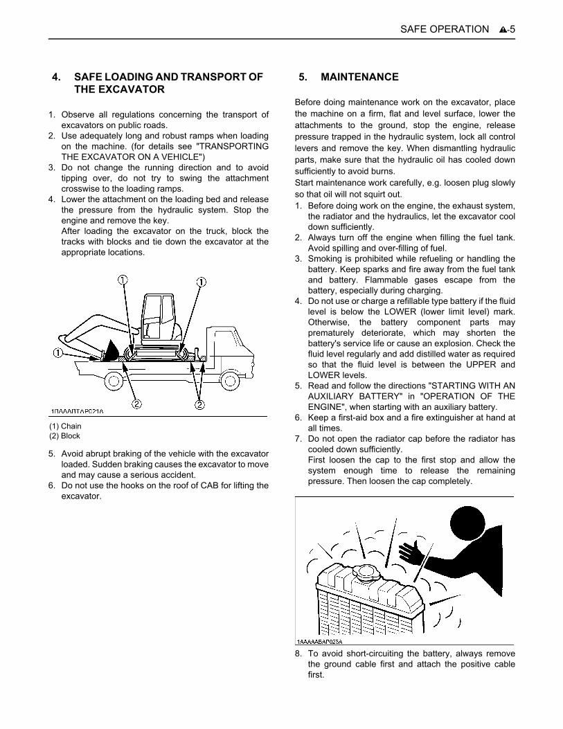
8. When towing the excavator or pulling a load, the loadmust be less than the strength of the towing lineattached to excavator.
9. The towing eye should not be used for tie down orlifting of the machine.
10.When the excavator is parked or left unattended on aslope, be sure to put the bucket on the ground andplace all control levers in neutral position, then bracethe tracks with chocks.A When working in groups, always let the others
know what you are going to do before you do it.Keep others away from the machine working area.Be sure to lock the boom swing pedal when theboom swing function is not used.
11.For details of operating the excavator, see the"EXCAVATOR OPERATION" section.
C Safety for childrenTragedy can occur if the operator is not alert to thepresence of children. Children generally are attracted tomachines and the work they do.
1. Never assume that children will remain where you lastsaw them.
2. Keep children out of the work area and under thewatchful eye of another responsible adult.
3. Be alert and shut your machine down if children enterthe work area.
4. Never carry children on your machine. There is not asafe place for them to ride. They may fall off and be runover or interfere with your control of the machine.
5. Never allow children to operate the machine evenunder adult supervision.
6. Never allow children to play on the machine or on theattachments.
7. Use extra caution when backing up. Look behind anddown to make sure the area clear before moving.
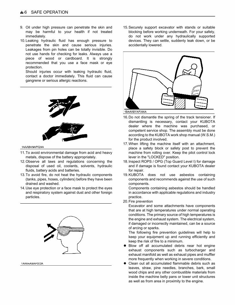
Before leaving the machine,A Park the excavator on a firm, flat and level surface. If
this is not possible, park across the slope.A Lower the attachments and the dozer blade to the
ground.A Stop the engine.A Release pressure in the hydraulic system.A Lock all control levers.A Remove the key.A Lock the cab door (if equipped)
Max. drawbar pull at coupling hook 72 kN (7340 kgf)
Max. vertical load at coupling hook 40 kN (4080 kgf)
(1) Tow line
3. AFTER OPERATION
(1) Pilot control lock lever (A) "UNLOCK"(B) "LOCKED"
-5SAFE OPERATION
1. Observe all regulations concerning the transport ofexcavators on public roads.
2. Use adequately long and robust ramps when loadingon the machine. (for details see "TRANSPORTINGTHE EXCAVATOR ON A VEHICLE")
3. Do not change the running direction and to avoidtipping over, do not try to swing the attachmentcrosswise to the loading ramps.
4. Lower the attachment on the loading bed and releasethe pressure from the hydraulic system. Stop theengine and remove the key.After loading the excavator on the truck, block thetracks with blocks and tie down the excavator at theappropriate locations.
5. Avoid abrupt braking of the vehicle with the excavatorloaded. Sudden braking causes the excavator to moveand may cause a serious accident.
6. Do not use the hooks on the roof of CAB for lifting theexcavator.
Before doing maintenance work on the excavator, placethe machine on a firm, flat and level surface, lower theattachments to the ground, stop the engine, releasepressure trapped in the hydraulic system, lock all controllevers and remove the key. When dismantling hydraulicparts, make sure that the hydraulic oil has cooled downsufficiently to avoid burns.Start maintenance work carefully, e.g. loosen plug slowlyso that oil will not squirt out.1. Before doing work on the engine, the exhaust system,
the radiator and the hydraulics, let the excavator cooldown sufficiently.
2. Always turn off the engine when filling the fuel tank.Avoid spilling and over-filling of fuel.
3. Smoking is prohibited while refueling or handling thebattery. Keep sparks and fire away from the fuel tankand battery. Flammable gases escape from thebattery, especially during charging.
4. Do not use or charge a refillable type battery if the fluidlevel is below the LOWER (lower limit level) mark.Otherwise, the battery component parts mayprematurely deteriorate, which may shorten thebattery's service life or cause an explosion. Check thefluid level regularly and add distilled water as requiredso that the fluid level is between the UPPER andLOWER levels.
5. Read and follow the directions "STARTING WITH ANAUXILIARY BATTERY" in "OPERATION OF THEENGINE", when starting with an auxiliary battery.
6. Keep a first-aid box and a fire extinguisher at hand atall times.
7. Do not open the radiator cap before the radiator hascooled down sufficiently.First loosen the cap to the first stop and allow thesystem enough time to release the remainingpressure. Then loosen the cap completely.
8. To avoid short-circuiting the battery, always removethe ground cable first and attach the positive cablefirst.
4. SAFE LOADING AND TRANSPORT OF THE EXCAVATOR
(1) Chain(2) Block
5. MAINTENANCE
SAFE OPERATION-6
9. Oil under high pressure can penetrate the skin andmay be harmful to your health if not treatedimmediately.
10.Leaking hydraulic fluid has enough pressure topenetrate the skin and cause serious injuries.Leakages from pin holes can be totally invisible. Donot use hands for checking for leaks. Always use apiece of wood or cardboard. It is stronglyrecommended that you use a face mask or eyeprotection.Should injuries occur with leaking hydraulic fluid,contact a doctor immediately. This fluid can causegangrene or serious allergic reactions.
11.To avoid environmental damage from acid and heavymetals, dispose of the battery appropriately.
12.Observe all laws and regulations concerning thedisposal of used oil, coolants, solvents, hydraulicfluids, battery acids and batteries.
13.To avoid fire, do not heat the hydraulic components(tanks, pipes, hoses, cylinders) before they have beendrained and washed.
14.Use eye protection or a face mask to protect the eyesand respiratory system against dust and other foreignparticles.
15.Securely support excavator with stands or suitableblocking before working underneath. For your safety,do not work under any hydraulically supporteddevices. They can settle, suddenly leak down, or beaccidentally lowered.
16.Do not dismantle the spring of the track tensioner. Ifdismantling is necessary, contact your KUBOTAdealer where the machine was purchased, orcompetent service shop. The assembly must be doneaccording to the KUBOTA work shop manual (W.S.M.)for the product involved.
17.When lifting the machine itself with an attachment,place a safety block or safety post to prevent themachine from rolling over. Keep the pilot control locklever in the "LOCKED" position.
18. Inspect ROPS / OPG (Top Guard Level I) for damageand if damage is found contact your KUBOTA dealerfor repair.
19.KUBOTA does not use asbestos containingcomponents and recommends against the use of suchcomponents.Components containing asbestos should be handledin accordance with applicable regulations and industrypractice.
20.Fire preventionExcavator and some attachments have componentsthat are at high temperatures under normal operatingconditions. The primary source of high temperatures isthe engine and exhaust system. The electrical system,if damaged or incorrectly maintained, can be a sourceof arcing or sparks.The following fire prevention guidelines will help tokeep your equipment up and running efficiently andkeep the risk of fire to a minimum.
A Blow off all accumulated debris near hot engineexhaust components such as turbocharger andexhaust manifold as well as exhaust pipes and mufflermore frequently when working in severe conditions.
A Clean out all accumulated flammable debris such asleaves, straw, pine needles, branches, bark, smallwood chips and any other combustible materials frominside the machine belly pans or lower unit structuresas well as from area in proximity to the engine.

-7SAFE OPERATION
A Inspect all fuel lines and hydraulic hoses for wear or fordeterioration. Replace them immediately if they beginto leak.
A Examine electrical wiring and connectors frequentlyfor damage. Repair any wires that are loose or frayedbefore operating the machine. Clean all electricalconnections and tighten all electrical connections asnecessary.
A Inspect the exhaust system daily for any signs ofleakage. Check for broken pipes and muffler and alsofor loose or missing bolts, nuts and clamps. If anyexhaust leaks or fractured parts are found, repairsmust be completed prior to operation.
A Always keep a multipurpose fire extinguisher on ornear the machine. Be familiar with the operation of thefire extinguisher.

SAFE OPERATION-8
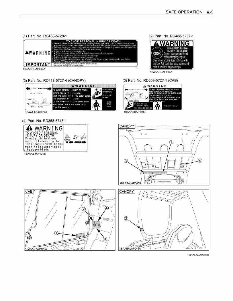
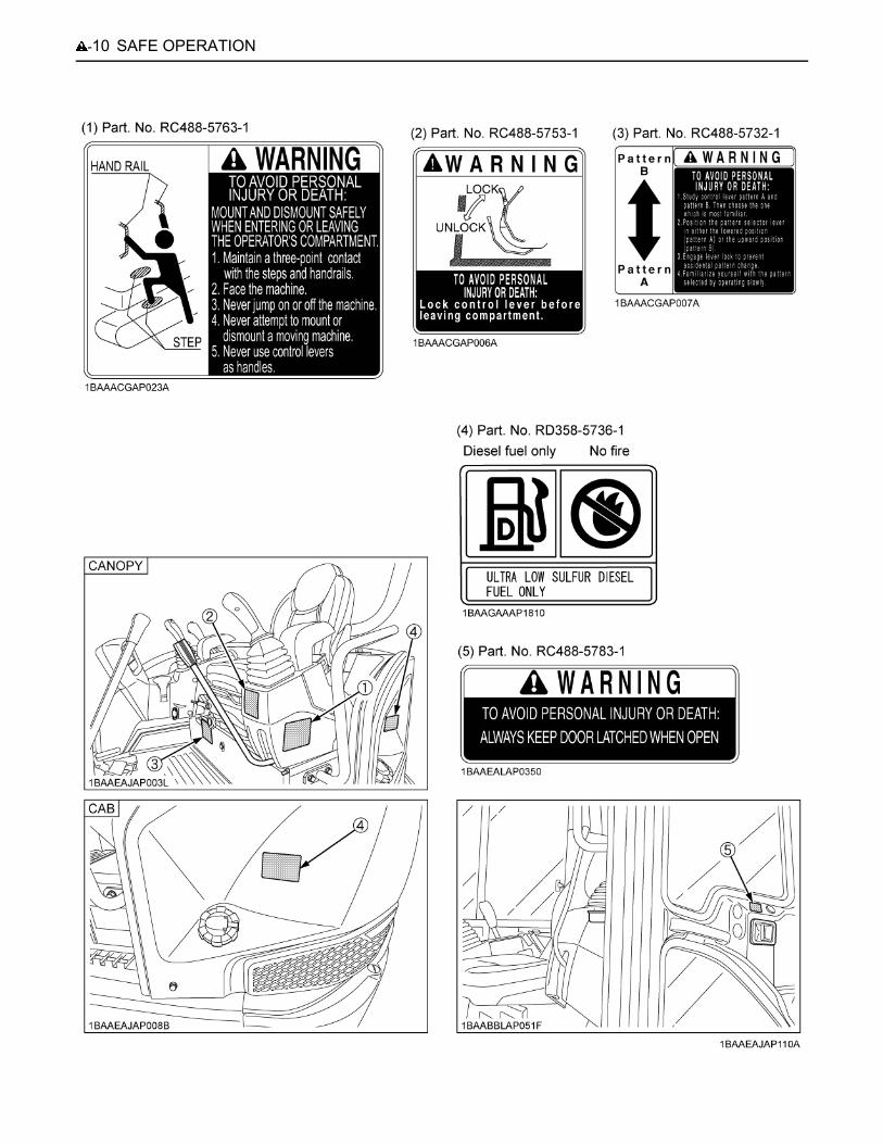
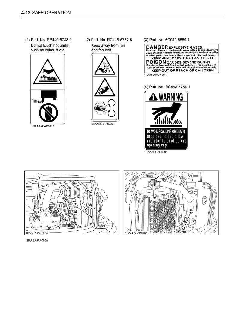
6. DANGER, WARNING AND CAUTION LABELS
-9SAFE OPERATION
SAFE OPERATION-10

-11SAFE OPERATION
SAFE OPERATION-12

-13SAFE OPERATION

SAFE OPERATION-14
1. Keep danger, warning and caution labels clean and free from obstructing material.2. Clean danger, warning and caution labels with soap and water, and dry with a soft cloth. 3. Replace damaged or missing danger, warning and caution labels with new labels from your KUBOTA dealer.4. If a component with danger, warning and caution label(s) affixed is replaced with new part, make sure new label(s) is
(are) attached in the same location(s) as the replaced component.5. Mount new danger, warning and caution labels by applying on a clean dry surface and pressing any bubbles to outside
edge.
7. CARE OF DANGER, WARNING AND CAUTION LABELS
1DEALER SERVICE
DEALER SERVICE
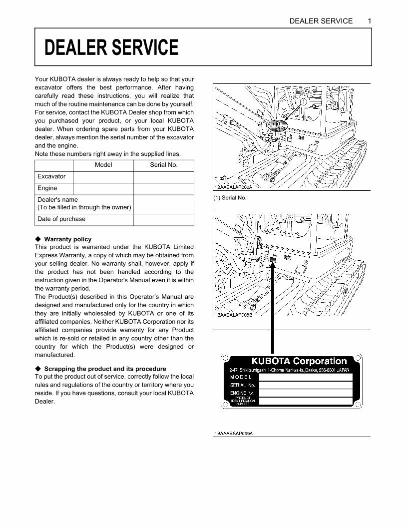
Your KUBOTA dealer is always ready to help so that yourexcavator offers the best performance. After havingcarefully read these instructions, you will realize thatmuch of the routine maintenance can be done by yourself.For service, contact the KUBOTA Dealer shop from whichyou purchased your product, or your local KUBOTAdealer. When ordering spare parts from your KUBOTAdealer, always mention the serial number of the excavatorand the engine.Note these numbers right away in the supplied lines.C Warranty policyThis product is warranted under the KUBOTA LimitedExpress Warranty, a copy of which may be obtained fromyour selling dealer. No warranty shall, however, apply ifthe product has not been handled according to theinstruction given in the Operator's Manual even it is withinthe warranty period.The Product(s) described in this Operator’s Manual aredesigned and manufactured only for the country in whichthey are initially wholesaled by KUBOTA or one of itsaffiliated companies. Neither KUBOTA Corporation nor itsaffiliated companies provide warranty for any Productwhich is re-sold or retailed in any country other than thecountry for which the Product(s) were designed ormanufactured.
C Scrapping the product and its procedureTo put the product out of service, correctly follow the localrules and regulations of the country or territory where youreside. If you have questions, consult your local KUBOTADealer.
Model Serial No.
Excavator
Engine
Dealer's name(To be filled in through the owner)
Date of purchase
(1) Serial No.

DEALER SERVICE2
(1) Engine serial No.

3TECHNICAL DATA
TECHNICAL DATA
A Above dimensions are based on the machine with rubber trucks.A Specifications subject to change without notice.D With unloaded digging bucket. (Q/C BUCKET)D Firm compacted soil.D Operators must exercise extra caution and follow instructions in the operator's manual.D Worse condition or heavier attachment to the above will decrease climbing angle.
KUBOTA EXCAVATORModel name U35-4Type Canopy CABOperating weight (including operator's) kg 3687 3833
Engine
Type Water cooled 4 cycle diesel engine with 3 cylinder
Model name D1703-M-DI-E4-US1 D1703-M-DI-E4-US2
Total displacement cc 1647
Engine power SAE gross kW (HP) 18.5 (25)
Rated speed rpm 2200
Low idle speed rpm 1300 ~ 1350
Performance
Unit swing speed rpm 8.5
Travel speedFast km/h (mph) 4.6 (2.9)
Slow km/h (mph) 3.0 (1.9)
Ground pressure(With operator)
kPa (kgf/ )
33.7(0.34)
35.1(0.36)
Climbing angle % (deg) *58 (30)
Angle in case ofcrossing slope % (deg) *27 (15)
Dozer
Width x Height mm 1700 x 341
Max swing angle
Left deg ---
Right deg ---
Boom swing angleLeft rad (deg) 1.22 (70)
Right rad (deg) 0.83 (48)
Pressureconnectionforattachments
Max.displacement (Theoretical) L/min 60.5 (AUX1 port)
Max. pressure MPa (kgf/ )
17.2(175)
Fuel tank capacity L 45.1

4 DESCRIPTION OF MACHINE PARTS
DESCRIPTION OF MACHINE PARTS
DEPICTED CONTENTS(1) Bucket cylinder (2) Arm (3) Bucket link 2 and 3(4) Bucket link 1(5) Bucket
(6) Swing bracket(7) Arm cylinder(8) Canopy(9) Seat(10) Swing frame
(11) Boom cylinder(12) Dozer cylinder(13) Dozer blade(14) Boom(15) Cab
(16) Drive sprocket(17) Track roller(18) Front idler

5INSTRUMENT PANEL AND CONTROL ELEMENTS
INSTRUMENT PANEL AND CONTROL ELEMENTS
B Instrument Panel, Switch(1) LCD(2) Horn switch
(3) Travel speed switch(4) Starter switch
(5) Throttle potentiometer(6) Light switch
(7) Auto idle control switch(8) One way hold switch
Ref. pageStarter switch............................................................. 7Display selector switch............................................... 8LCD........................................................................... 8Fuel gaugeCoolant temperature gaugeHour meterEngine tachometerGlow indicatorWarning lamp............................................................. 11Information switch...................................................... 11User setting switch..................................................... 13Horn switch................................................................ 18
(9) User setting switch (Switch 1)(10) - (Switch 2)(11) AUX port enable switch (Switch 3)(12) Information switch (Switch 4)(13) Display selector switch (Switch 5)
Light switch................................................................ 18AUX port enable switch.............................................. 18Auto idle control switch............................................... 19Throttle potentiometer................................................ 19Travel speed switch................................................... 19
6 INSTRUMENT PANEL AND CONTROL ELEMENTS
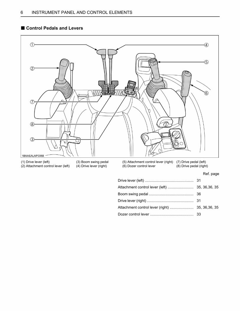
B Control Pedals and Levers
(1) Drive lever (left)(2) Attachment control lever (left)
(3) Boom swing pedal(4) Drive lever (right)
(5) Attachment control lever (right)(6) Dozer control lever
(7) Drive pedal (left)(8) Drive pedal (right)
Ref. page
Drive lever (left) ............................................... 31
Attachment control lever (left) ......................... 35, 36,36, 35
Boom swing pedal ........................................... 36
Drive lever (right) ............................................. 31
Attachment control lever (right) ....................... 35, 36,36, 35
Dozer control lever .......................................... 33

7CHECKS BEFORE START
CHECKS BEFORE START
DAILY CHECKSIn order to avoid damage, it is important to check thecondition of the excavator before starting.To avoid personal injury or death:A Do maintenance work on the excavator only on
level ground with the engine off and the pilotcontrol lock lever in the "LOCKED" position.
ChecksGo around the excavator and check for visual damageand wear. Check coolant level. (See "DAILY CHECKS" in"MAINTENANCE" section.)Check fuel level.Check engine oil level.Check hydraulic fluid level.Check air filter for clogging.Check all grease points.Check all control lamps, indicators, tachometer and hourmeter.Confirm all controls move freely and do not stick.Check the light system. Check the seat belt and the ROPS / OPG (Top GuardLevel I) safety device. Check the condition of the safety and warning labels.(See "DANGER, WARNING AND CAUTION LABELS" in"SAFE OPERATION" section.) Inspect ROPS / OPG (Top Guard Level I) for damage andif damage is found, contact your KUBOTA dealer forrepair.
CHECKING THE DEVICESBStarter SwitchA [STOP]
The key can be inserted at the "STOP" position.A [RUN]
Turn the key one click from the "STOP" position to the"RUN" position. All the circuitry gets energized to startpreheating. The glow indicator is displayed.To check for any lamp breakage, however, the lamplights up and stays on for about 1 second.
A [START]Move the pilot control lock lever to the "LOCKED"position. Turn the key from the "RUN" position anotherclick to the "START" position. The starter motor is thenactivated to get the engine started.Release your hand from the key, and the key returnsitself to the "RUN" position. In other words, once theengine has started, be sure to free the key.
A If the key is repositioned from "RUN" to "STOP" but notpulled out, the message "pull out key" appearsonscreen.
A With the key off and pulled out, nothing appearsonscreen.
[Status with the key off but not pulled out]
(1) Starter switch (A) STOP(B) RUN(C) START

CHECKS BEFORE START8
BDisplay Selector SwitchPress the display selector switch while the engine isrunning. The LCD meter display will change from oneindication mode to the other.Change the two-mode display according to your jobs.
C AUX port in use
A Even with the starter key not yet inserted, press theelectronic meter's user setting switch or the displayselector switch, and the LCD shows the hour meter,fuel gauge, water temperature gauge and clock for 10seconds.
BLCD for Normal OperationC Fuel gauge
To avoid personal injury or death:A Before adding fuel, be sure to stop the engine.A Be sure to keep open flame away from the
machine. Otherwise a fire may result.
With the starter key at the "RUN" position, the fuelremaining in the fuel tank is indicated in the block.
If the fuel runs short, open the cap and refuel the tank.
A If the fuel gauge indicator is near the "E" or the "Feedfuel" message appears, add fuel as soon as possible.If the indicator is near "E" and the machine is operatedon a slope, the engine may run out of fuel.
A To open the fuel cap, keep the key inserted.
(1) Display selector switch
(1) Display selector switch
(1) Fuel gauge (A) "E"
(1) Fuel cap
9CHECKS BEFORE START
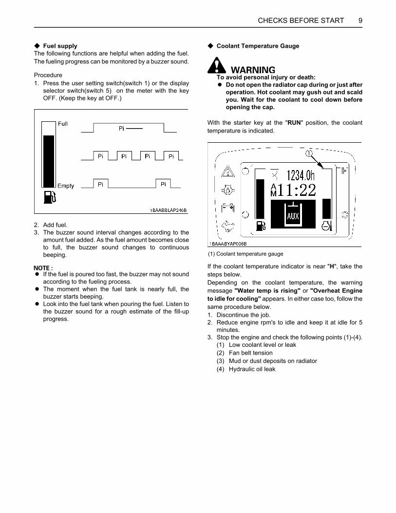
C Fuel supplyThe following functions are helpful when adding the fuel.The fueling progress can be monitored by a buzzer sound.
Procedure1. Press the user setting switch(switch 1) or the display
selector switch(switch 5) on the meter with the keyOFF. (Keep the key at OFF.)
2. Add fuel.3. The buzzer sound interval changes according to the
amount fuel added. As the fuel amount becomes closeto full, the buzzer sound changes to continuousbeeping.
A If the fuel is poured too fast, the buzzer may not soundaccording to the fueling process.
A The moment when the fuel tank is nearly full, thebuzzer starts beeping.
A Look into the fuel tank when pouring the fuel. Listen tothe buzzer sound for a rough estimate of the fill-upprogress.
C Coolant Temperature Gauge
To avoid personal injury or death:A Do not open the radiator cap during or just after
operation. Hot coolant may gush out and scaldyou. Wait for the coolant to cool down beforeopening the cap.
With the starter key at the "RUN" position, the coolanttemperature is indicated.
If the coolant temperature indicator is near "H", take thesteps below.Depending on the coolant temperature, the warningmessage "Water temp is rising" or "Overheat Engineto idle for cooling" appears. In either case too, follow thesame procedure below.1. Discontinue the job.2. Reduce engine rpm's to idle and keep it at idle for 5
minutes.3. Stop the engine and check the following points (1)-(4).
(1) Low coolant level or leak(2) Fan belt tension(3) Mud or dust deposits on radiator(4) Hydraulic oil leak
(1) Coolant temperature gauge
CHECKS BEFORE START10
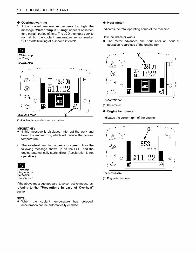
C Overheat warning1. If the coolant temperature becomes too high, the
message "Water temp is Rising" appears onscreenfor a certain period of time. The LCD then gets back tonormal, but the coolant temperature sensor marker" " starts blinking at 1-second intervals.
A If this message is displayed, interrupt the work andlower the engine rpm, which will reduce the coolanttemperature.
2. The overheat warning appears onscreen. Also thefollowing message shows up on the LCD, and theengine automatically starts idling. (Acceleration is notoperative.)
If the above message appears, take corrective measures,referring to the "Precautions in case of Overheat"section.
A When the coolant temperature has dropped,acceleration can be automatically enabled.
C Hour-meter
Indicates the total operating hours of the machine.
How the indicator worksA The meter advances one hour after an hour of
operation regardless of the engine rpm.
C Engine tachometer
Indicates the current rpm of the engine.(1) Coolant temperature sensor marker
(1) Hour-meter
(1) Engine tachometer

11CHECKS BEFORE START
C Glow indicatorThe indicator is displayed when the starter key is turnedto the "RUN" position but the engine requires preheating.Wait until the indicator goes out, and then start the engine.
BWarning LampThe warning lamp is used to indicate broken wire, short-circuit, fuel shortage and other problems.The warning lamp starts flashing in red if any problemoccurs. If the system senses a in warning signal, thewarning lamp starts flashing in yellow.
A If the warning illuminates, do not just look at the meter;carry out the appropriate inspection and correctionaccordingly.(See "REGULAR CHECKS AND MAINTENANCEWORK" section)
A If any warnings and problems are displayed, an alarmbuzzer will beep. (See "LIST OF SCREENS" sectionfor detail.)
A Consult your local KUBOTA dealer from detailsconcerning care and maintenance.
BLCD for WarningC Remaining fuel warning
When the fuel level is very low, the lamp (yellow) startsflashing and the following message appears in thedisplay.
A After a short period of time, the display comes back tonormal.
A After a short period of time, the message shows upagain.
A Even while in the normal display mode, the warninglamp keeps on blinking.
A To see what warning is being given out, press thedisplay selector switch. The current warning can thenbe identified.
C Battery charge warning
If the starter key is turned to the "RUN" position withoutstarting the engine, and the charging lamp stays off, thecharging system has failed. If such occurs, immediatelycontact your local dealer for repair.
(1) Glow indicator
(1) Warning lamp (red, yellow)
(1) Charging lamp

CHECKS BEFORE START12
C Engine oil pressure low warning
When the engine oil pressure drops too low, the lamp(red) starts flashing and the following message appears inthe display.Immediately stop the engine and check the engine oillevel.
A If the starter key is turned to the "RUN" positionwithout running the engine and the oil lamp stays off,then the hydraulic system may have failed.If such occurs, immediately contact your local dealerfor repair.
C Various error warningsIf any components are detected to be in trouble, thefollowing message or similar appears onscreen.(See "LIST OF SCREENS" section)
For Example;
C Information
A " mark" may appear together with a warningmessage.If such occurs, the details can be checked by pressing theinformation switch.When contacting your local dealer for repair, notify themof the information provided.
For Example;Press the information switch, and a detail such as shownbelow appears.
A Press the information switch again, and the displaygoes back to the previous screen.
(1) Oil lamp
(1) Information switch

13CHECKS BEFORE START
A If you have any question, consult your local KUBOTADealer.
BSetting the Clock1. Turn the starter key to the "RUN" position.
2. Press the switch 1 to make the log record/periodiccheck/clock set screen appear.
3. Press the switch 2 twice to move the cursor intoposition. Then press the save switch 5 to make thefollowing screen appear. By pressing the switch 4, theyear, month, day, hour and minute will be selected inthis order. Select an item to readjust.
Press the switch (Switch 2) and the numeric setting willbe smaller.Press the switch (Switch 3) and the numeric setting willbe larger.
Hold down the or switch, and the numeric setting willchange quickly.Press the switch (Switch 4), and the year, month, day,hour and minute will be selected in this order.
4. Save the new setting with the switch (Switch 5).Press this switch 5 again to set the clock.
User settings
(1) Starter switch (A) STOP(B) RUN(C) START
(1) Switch 1(2) Switch 5(3) Cursor
(4) Switch 2 and 3(5) Switch 4
(1) Switch 5(2) Switch 2
(3) Switch 3(4) Switch 4
(1) Switch 5

CHECKS BEFORE START14
[Status after setting the clock]
A Be careful not to accidentally press the switch 5 on theclock setting screen. Otherwise the seconds will be setto "00" and the clock will show the wrong time.
A If the clock is interrupted, for example when the batteryis disconnected, the following message appearsonscreen. Press the switch 5 to set the clock again.
A When the user setting switch (Switch 1) is pressed onthe clock setting screen, the clock is not readjustedand returns to the previous menu screen.
BReordering the year/month/day and Changing the AM/PM System to the 24-hour One
1. On the user setting screen, select "VariousSettings".
2. Select "Calendar/Clock Set" menu screen.
(1) Switch 5
(1) Switch 5

15CHECKS BEFORE START
3. Press the switch 5 and the following detailed screenshows up.
(1) Using the switch 2 and 3, move up and down theitems. The year/month/day on Side (A) will bereordered.
(2) Using the switch 4, move the cursor to Side (B).Select the "AM/PM" system or the "24-hour"system.
(3) Press the switch 5, and the new settings will bemade.If the switch 1 is pressed, the previous settings willremain.
BLog RecordThe log record helps you check the last 3-month operatingrecord of the machine. Take the following steps.
1. Set the starter key to the "RUN" position.
2. Press the switch 1 to make the menu appearonscreen.
3. Press the switch 2 and 3 to select the log record. Fixthis choice with the switch (Switch 5).
4. Press the switch 5 to make the calendar appearonscreen.Press the switch 2, and the log records (machine'soperating days and operating hours) for the last monthand the month before last (90 days ago) can bereviewed.The highlighted days indicate when the machine wasoperated.
A Some days may appear marked with [-] when the logrecord is unknown because of a new setting of theclock, a disconnection of the battery or other factors.
(1) Switch 1(2) Switch 2 and 3(3) Switch 4(4) Switch 5
(A) Year/month/day display(B) Clock display
(1) Starter switch (A) "STOP"(B) "RUN"(C) "START"
(1) Switch 1(2) Switch 5
(3) Cursor(4) Switch 2 and 3
(1) Switch 5(2) Switch 2, 3 and 4

CHECKS BEFORE START16
BPeriodic CheckThe following message appears on the LCD 10 hoursbefore a periodic check.
Press the switch 4 to see the check results.
Do the following servicing listed below.
A When the servicing has been completed, turn the keyswitch ON and OFF 10 times or more and the checkscreen automatically disappears.
A When the periodic check interval has passed, themessage "Periodic Check Passed" shows up.Immediately perform the specified servicing.
A The periodic check screen can also be preset to bemade to disappear manually only. To do this, it isnecessary to select "Periodic Check" on the usersetting menu.For make this setting, contact your local dealer.
BIf All the Check Points are not Displayed at a Glance on a Single Screen
1. Press the switch 4.2. Each time the switch 2 or 3 is pressed, the check
points scrolled up or down.
(1) Switch 4
(1) Switch 4(2) Switch 2
(3) Switch 3

17CHECKS BEFORE START
C Service hour meterWhen the hour meter reaches the hours circled in the maintenance list below, a message appears. The message showsup as follows.
No. Check points MeasuresHour meter indicator
Intervals50 100 250 300 500 550 750 800 1000 2000
1 Engine oil (CF-4)change
every 250 hrs
2 Hydraulic oil every 1000 hrs
3 Air filter element
Outer element
replace
every 1000 hrs
Inner element
every 1000 hrs
4 Fuel filter every 500 hrs
5 Engine oil filter every 250 hrs
6 Drive unit oil change every 500 hrs
7 Hydraulic return filter element
replace
every 500 hrs
8 Hydraulic suction filter element
every 1000 hrs
9 Pilot filter replace every 1000 hrs
10 Idlor, Track roller, grease - every
2000 hrs
11 Breather filter replace every 500 hrs
First operation

CHECKS BEFORE START18
BWhen the Check-up is CompletedWhen the check-up is completed, perform the followingprocedure to make the Periodic Check disappear from thescreen.1. The message below appears onscreen to prompt the
completion of the check-up.2. To take a look at the check points, press the
information switch. The check points appearonscreen.
3. When the check-up has been completed, press theswitch 5. If not, press the switch 1 to go back to theprevious screen.
BHorn Switch
BLight SwitchWhen the starter switch is in position "RUN", the workinglight(s) and CAB light(s) will be switched on by pressingthe switch.
C Night operation
To avoid personal injury or death:A When the working light and CAB light alone do
not provide sufficient visibility, prepareadditional stationary artificial lighting andobserve safety rules for night work.
BAUX Port Enable SwitchIt is possible to freely readjust the actuator's maximumflow rate in the AUX operating mode.(See "AUXILIARY PORT OPERATION" section fordetail.)
(1) Switch 4(2) Switch 1(3) Switch 5
(1) Horn switch
(1) Light switch
(1) AUX port enable switch
19CHECKS BEFORE START
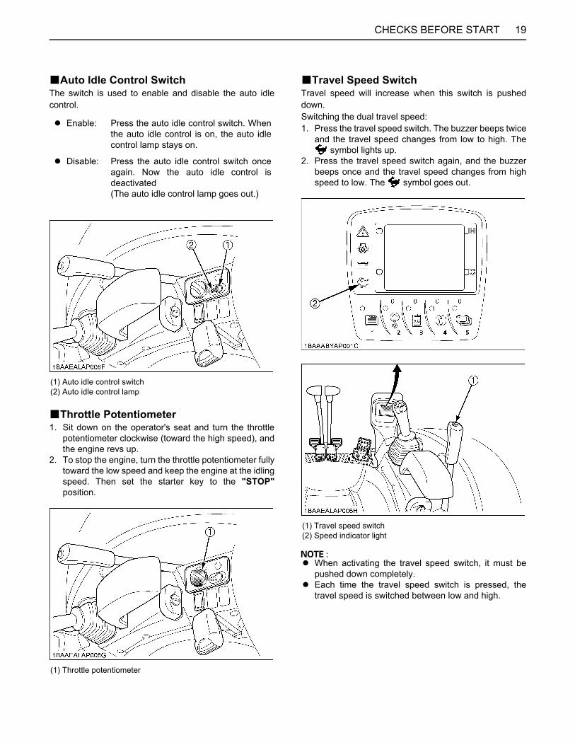
BAuto Idle Control SwitchThe switch is used to enable and disable the auto idlecontrol.
BThrottle Potentiometer1. Sit down on the operator's seat and turn the throttle
potentiometer clockwise (toward the high speed), andthe engine revs up.
2. To stop the engine, turn the throttle potentiometer fullytoward the low speed and keep the engine at the idlingspeed. Then set the starter key to the "STOP"position.
BTravel Speed SwitchTravel speed will increase when this switch is pusheddown.Switching the dual travel speed:1. Press the travel speed switch. The buzzer beeps twice
and the travel speed changes from low to high. The symbol lights up.
2. Press the travel speed switch again, and the buzzerbeeps once and the travel speed changes from highspeed to low. The symbol goes out.
A When activating the travel speed switch, it must bepushed down completely.
A Each time the travel speed switch is pressed, thetravel speed is switched between low and high.
A Enable: Press the auto idle control switch. Whenthe auto idle control is on, the auto idlecontrol lamp stays on.
A Disable: Press the auto idle control switch onceagain. Now the auto idle control isdeactivated(The auto idle control lamp goes out.)
(1) Auto idle control switch(2) Auto idle control lamp
(1) Throttle potentiometer
(1) Travel speed switch(2) Speed indicator light

CHECKS BEFORE START20
A The travel speed automatically changes into firstspeed (low speed) when the drive resistanceincreases while traveling second speed (high speed).Thereafter, when the resistance decreases, it returnsto second speed.
A If the tracks are clogged with sand or gravel whileworking on soft ground, lift up the track with the help ofthe boom, arm and bucket and dozer blade, and let thetrack rotate to remove the sand and gravel.
To avoid personal injury or death:A Do not push the dozer control lever into the
float position as this will cause the machine tosuddenly drop.
To avoid serious injury or death:A Do not work under the machine in this
condition.
CAB TYPE MACHINESBWiper/Washer SwitchTo engage the wiper, turn on the switch for the wiper whenthe starter key is in the "RUN" position. A further push onthe switch will activate the washer system. Even when thewiper switch is in the "OFF" position, the washer switchfunctions if it is pressed.A Do not activate the washer switch if the tank for the
cleaning fluid is empty; the pump can be damaged.A Do not activate the wiper switch if the window is dry. In
this case, make sure that cleaning fluid is applied tothe pane before activating the wiper.
A In frosty conditions, make sure that the wiper blade isnot frozen to the glass before switching-on. The motorcan be damaged if the wiper system is used undersuch conditions.
BInterior LampTo turn on the interior lamp, set the interior lamp switch tothe "ON" positions.
(A) "Rotate to remove sand and gravel"
(1) Wiper switch
(1) Interior lamp(2) Interior lamp switch
(A) "ON"(B) "OFF"
21CHECKS BEFORE START
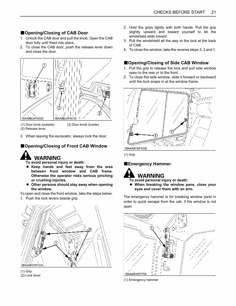
BOpening/Closing of CAB Door1. Unlock the CAB door and pull the knob. Open the CAB
door fully until fixed into place.2. To close the CAB door, push the release lever down
and close the door.
3. When leaving the excavator, always lock the door.
BOpening/Closing of Front CAB Window
To avoid personal injury or death:A Keep hands and feet away from the area
between front window and CAB frame.Otherwise the operator risks serious pinchingor crushing injuries.
A Other persons should stay away when openingthe window.
To open and close the front window, take the steps below.1. Push the lock levers beside grip.
2. Hold the grips tightly with both hands. Pull the gripslightly upward and toward yourself to let thewindshield slide inward.
3. Pull the windshield all the way to the lock at the backof CAB.
4. To close the window, take the reverse steps 3, 2 and 1.
BOpening/Closing of Side CAB Window1. Pull the grip to release the lock and pull side window
open to the rear or to the front.2. To close the side window, slide it forward or backward
until the lock snaps in at the window frame.
BEmergency Hammer
To avoid personal injury or death:A When breaking the window pane, close your
eyes and cover them with an arm.
The emergency hammer is for breaking window pane inorder to quick escape from the cab, if the window is notopen.
(1) Door knob (outside)(2) Release lever
(3) Door knob (inside)
(1) Grip(2) Lock lever
(1) Grip
(1) Emergency hammer
CHECKS BEFORE START22
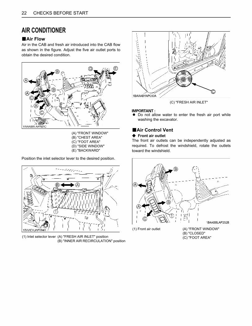
AIR CONDITIONERBAir FlowAir in the CAB and fresh air introduced into the CAB flowas shown in the figure. Adjust the five air outlet ports toobtain the desired condition.
Position the inlet selector lever to the desired position.
A Do not allow water to enter the fresh air port whilewashing the excavator.
BAir Control VentC Front air outletThe front air outlets can be independently adjusted asrequired. To defrost the windshield, rotate the outletstoward the windshield.
(A) "FRONT WINDOW"(B) "CHEST AREA"(C) "FOOT AREA"(D) "SIDE WINDOW"(E) "BACKWARD"
(1) Inlet selector lever (A) "FRESH AIR INLET" position(B) "INNER AIR RECIRCULATION" position
(C) "FRESH AIR INLET"
(1) Front air outlet (A) "FRONT WINDOW"(B) "CLOSED"(C) "FOOT AREA"
23CHECKS BEFORE START
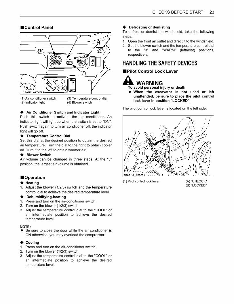
BControl Panel
C Air Conditioner Switch and Indicator LightPush this switch to activate the air conditioner. Anindicator light will light up when the switch is set to "ON".Push switch again to turn air conditioner off, the indicatorlight will go off.C Temperature Control DialSet this dial at the desired position to obtain the desiredair temperature. Turn the dial to the right to obtain coolerair. Turn it to the left to obtain warmer air.C Blower SwitchAir volume can be changed in three steps. At the "3"position, the largest air volume is obtained.
BOperationC Heating1. Adjust the blower (1/2/3) switch and the temperature
control dial to achieve the desired temperature level.C Dehumidifying-heating1. Press and turn on the air-conditioner switch.2. Turn on the blower (1/2/3) switch.3. Adjust the temperature control dial to the "COOL" or
an intermediate position to achieve the desiredtemperature level.
A Be sure to close the door while the air conditioner isON otherwise, you may overload the compressor.
C Cooling1. Press and turn on the air-conditioner switch.2. Turn on the blower (1/2/3) switch.3. Adjust the temperature control dial to the "COOL" or
an intermediate position to achieve the desiredtemperature level.
C Defrosting or demistingTo defrost or demist the windshield, take the followingsteps.1. Open the front air outlet and direct it to the windshield.2. Set the blower switch and the temperature control dial
to the "3" and "WARM" (leftmost) positions,respectively.
HANDLING THE SAFETY DEVICESBPilot Control Lock Lever
To avoid personal injury or death:A When the excavator is not used or left
unattended, be sure to place the pilot controllock lever in position "LOCKED".
The pilot control lock lever is located on the left side.
(1) Air conditioner switch(2) Indicator light
(3) Temperature control dial(4) Blower switch
(1) Pilot control lock lever (A) "UNLOCK"(B) "LOCKED"

24 OPERATION OF THE ENGINE
OPERATION OF THE ENGINE
To avoid personal injury or death:A Read "SAFE OPERATION" at the beginning of
this operator's manual.A Obey the danger, warning and caution labels
on the excavator. A To avoid the danger of exhaust fume (carbon
monoxide) poisoning, do not operate themachine in a closed building without properventilation.
A Always start the engine from the operator'sseat. Do not start the engine while standingnext to the excavator. Before starting theengine, sound the horn to get the attention ofpersons standing nearby.
A Do not use starting fluid or ether.A In order not to overload the battery and starter, avoid
engaging the starter for more than 10 sec.A If the engine does not start in 10 sec., please wait 20
sec. or more, before attempting to restart.
STARTING THE ENGINE
To avoid personal injury or death:A The operator should not depend solely on the
warning lamps, but should always conduct theroutine checks (see "MAINTENANCE").
Start the engine in the following manner:1. Before starting the engine, make sure that all control
levers are in the neutral positions.
2. Pull the pilot control lock lever all the way back.("LOCKED" position)
3. Put the throttle potentiometer in the middle between" " and " " symbols. The auto idle controlswitch is in the OFF position.(See "AUTO IDLE (AI) OPERATION" in the Excavatoroperation.)
(1) Horn switch
(1) Attachment control lever (left) (2) Drive lever (left) (3) Drive lever (right)(4) Attachment control lever (right) (5) Throttle potentiometer
(1) Throttle potentiometer(2) Auto idle control switch

25OPERATION OF THE ENGINE
4. Set the starter key to the "RUN" position. Hold the keyat this position until the " " mark on the display paneldisappears.
5. Now make sure the " " and " " marks appearonscreen. If not, the system has malfunctioned.Contact your local dealer for repairs.
6. Turn the key to the position "START" and releaseafter the engine has started.
7. Check if all warning lamps have gone out. Should awarning lamp still be lit up, stop the engine thenremove the key and check for the cause.
A The starter motor draws a large current. Avoid runningit longer than 10 seconds continuously.If the engine fails to start within 10 seconds, set thekey to the "STOP" position, wait for 20 seconds orlonger, and repeat the above steps 5 thru 7.
A If the battery is dead and must be connected toanother battery with jumper cable, be sure to use a12V battery. Never use 24V batteries.
A If you keep the pilot control lock lever at "UNLOCK"and try to start the engine, "Up Lever Lock" appearson the meter panel and the engine cannot be started.Before staring the engine, make sure the pilot controllock lever is set at the "LOCKED" position.
A When the engine starts, the meter may momentarilyturn off and a beep may sound. This is not a problem.
STARTING THE ENGINE UNDER COLD CONDITIONS
To avoid personal injury or death:A Make sure that the pilot control lock lever is in
the "LOCKED" position during warm up.
Start the engine in the following manner;1. Make sure the auto idle control switch is at the "OFF"
position (lamp off).2. Pull the pilot control lock lever all the way back.
("LOCKED" position)3. Insert the starter key into the starter switch.4. Turn the throttle potentiometer toward " " (high
speed) position.5. Set the starter key to the "RUN" position. Hold the key
at this position until the " " mark on the display paneldisappears.
6. Turn the starter key to the "START" position.7. Once the engine starts, release your hand from the
key. The key will return back to the "RUN" position.8. If the engine fails to start, set the starter key to the
"STOP" position, and repeat the above steps 5 thru 7.
A Let the engine warm up after start-up for approx. 10minutes under no load conditions. If the hydraulic fluidtemperature is too low, the operation will be affected.Do not operate the excavator under full load until theengine has sufficiently warmed up.
(1) Starter switch (A) "STOP"(B) "RUN"(C) "START"

OPERATION OF THE ENGINE26
STARTING WITH AN AUXILIARY BATTERY
To avoid personal injury or death:A Battery gases can explode.
Do not smoke and keep sparks and flamesaway.
A Do not start the engine with an auxiliary batteryif excavator battery is frozen.
A Do not connect the black jumper cable to thenegative (-) terminal of the excavator battery.
BObserve Following Guidelines when Starting with an Auxiliary Battery
1. Bring the helping machine with the same batteryvoltage as near as possible to the excavator.THE MACHINES MUST NOT COME IN CONTACTWITH EACH OTHER.
2. Bring the levers and pedal of both vehicles in theneutral position and put the pilot control lock lever inthe "LOCKED" position.
3. Wear eye protection and rubber gloves.4. Open the side cover. (See "Opening / closing of the
Side Cover" in "MAINTENANCE" section.)5. Ensure the vent caps are securely in place (if
equipped).6. Connect the terminal of the red jumper cable with the
plus (+) terminal of the low battery and connect theother end of the cable to the plus (+) terminal of theauxiliary battery.
7. Connect the black negative cable to the minus (-)terminal of the auxiliary battery.
8. Connect the other end of the black cable (coming fromthe auxiliary battery) to the excavator frame as faraway as possible from the low battery.
9. Start the engine of the helping machine and let it runfor a while. Start the excavator with the low battery.
10.Disconnect the jumper cables in the reverse sequence(Steps 8, 7, 6).
11.Replace the vent caps.
A This excavator has a negative (-) ground 12 Voltstarting system.
A Use only the same voltage when using an auxiliarybattery.
A Using a higher voltage will cause serious damage tothe electrical system. When using an auxiliary battery,only the compatible (same) voltage is permissible.
CHECK POINTS AFTER STARTING THE ENGINEAfter starting the engine, but before starting operation,check the following points:1. Put the throttle potentiometer in the middle between
" " and " " symbols and let the engine idle forapprox. five minutes. This allows the engine lubricantto warm up and penetrate every part of the engine.
2. Once the engine has warmed up, check:A the warning lamp "Engine oil pressure" has gone
out.A the warning lamp "Battery charge" goes out when
engine speed is increased.A the color of the exhaust is normal and no abnormal
noises or vibrations are heard or felt.A no fluid is leaking from pipes or hoses.
C Should any following conditions occur, stop theengine immediately.
A The engine rpm's increases or decreases suddenly. A Sudden abnormal noises are heard.A Exhaust is black.A Warning lamp for engine oil lights up during operation.
A In these cases, the excavator must be checked andserviced by your local the KUBOTA dealer.
(1) Low battery(2) Jumper cables(3) Auxiliary battery
27OPERATION OF THE ENGINE
STOPPING THE ENGINE
To avoid personal injury or death:A Do not keep the bucket or dozer in an elevated
position, as a person could accidentally touchthe levers and cause serious accidents.
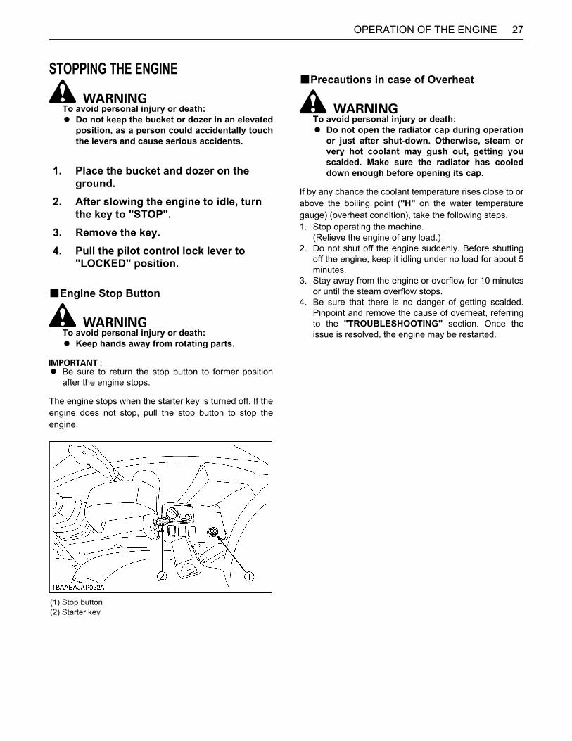
BEngine Stop Button
To avoid personal injury or death:A Keep hands away from rotating parts.
A Be sure to return the stop button to former positionafter the engine stops.
The engine stops when the starter key is turned off. If theengine does not stop, pull the stop button to stop theengine.
BPrecautions in case of Overheat
To avoid personal injury or death:A Do not open the radiator cap during operation
or just after shut-down. Otherwise, steam orvery hot coolant may gush out, getting youscalded. Make sure the radiator has cooleddown enough before opening its cap.
If by any chance the coolant temperature rises close to orabove the boiling point ("H" on the water temperaturegauge) (overheat condition), take the following steps.1. Stop operating the machine.
(Relieve the engine of any load.)2. Do not shut off the engine suddenly. Before shutting
off the engine, keep it idling under no load for about 5minutes.
3. Stay away from the engine or overflow for 10 minutesor until the steam overflow stops.
4. Be sure that there is no danger of getting scalded.Pinpoint and remove the cause of overheat, referringto the "TROUBLESHOOTING" section. Once theissue is resolved, the engine may be restarted.
1. Place the bucket and dozer on the ground.
2. After slowing the engine to idle, turn the key to "STOP".
3. Remove the key.4. Pull the pilot control lock lever to
"LOCKED" position.
(1) Stop button(2) Starter key
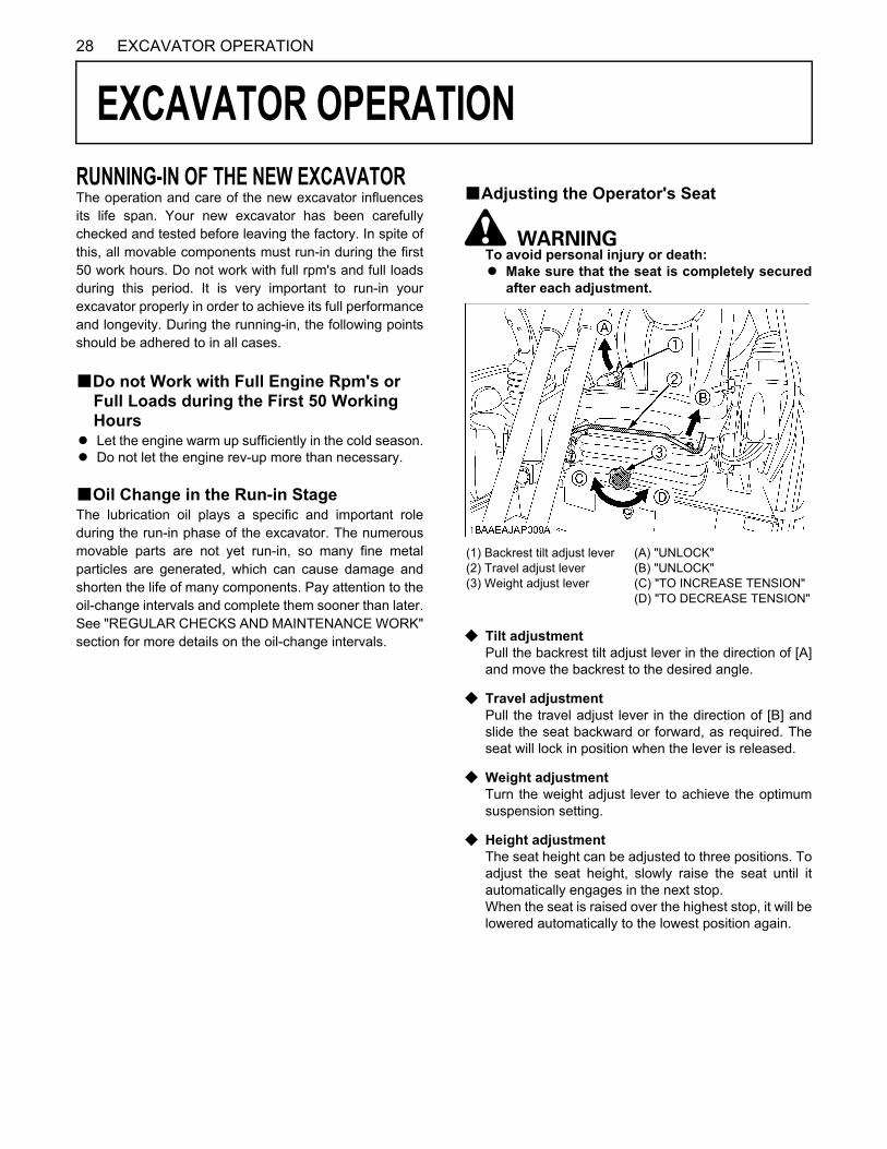
28 EXCAVATOR OPERATION
EXCAVATOR OPERATION
RUNNING-IN OF THE NEW EXCAVATORThe operation and care of the new excavator influencesits life span. Your new excavator has been carefullychecked and tested before leaving the factory. In spite ofthis, all movable components must run-in during the first50 work hours. Do not work with full rpm's and full loadsduring this period. It is very important to run-in yourexcavator properly in order to achieve its full performanceand longevity. During the running-in, the following pointsshould be adhered to in all cases.BDo not Work with Full Engine Rpm's or Full Loads during the First 50 Working Hours
A Let the engine warm up sufficiently in the cold season.A Do not let the engine rev-up more than necessary.
BOil Change in the Run-in StageThe lubrication oil plays a specific and important roleduring the run-in phase of the excavator. The numerousmovable parts are not yet run-in, so many fine metalparticles are generated, which can cause damage andshorten the life of many components. Pay attention to theoil-change intervals and complete them sooner than later.See "REGULAR CHECKS AND MAINTENANCE WORK"section for more details on the oil-change intervals.
BAdjusting the Operator's Seat
To avoid personal injury or death:A Make sure that the seat is completely secured
after each adjustment.
C Tilt adjustmentPull the backrest tilt adjust lever in the direction of [A]and move the backrest to the desired angle.
C Travel adjustmentPull the travel adjust lever in the direction of [B] andslide the seat backward or forward, as required. Theseat will lock in position when the lever is released.
C Weight adjustmentTurn the weight adjust lever to achieve the optimumsuspension setting.
C Height adjustmentThe seat height can be adjusted to three positions. Toadjust the seat height, slowly raise the seat until itautomatically engages in the next stop.When the seat is raised over the highest stop, it will belowered automatically to the lowest position again.
(1) Backrest tilt adjust lever(2) Travel adjust lever(3) Weight adjust lever
(A) "UNLOCK"(B) "UNLOCK"(C) "TO INCREASE TENSION"(D) "TO DECREASE TENSION"

29EXCAVATOR OPERATION
BSeat Belt
To avoid personal injury or death:A Always use the seat belt with a ROPS/OPG (Top
Guard Level I) protection structure. Adjust theseat to the optimal position and buckle up.
STARTING
To avoid personal injury or death:A No persons, other than those who have read
and understand this manual and who arefamiliar with the excavator, should be allowedto use the excavator.
A Do not allow any person other than theoperator to ride on the excavator.
A When operating, keep hands and body insideof the ROPS/OPG (Top Guard Level I)protective.
A Do not touch the control levers and the pedalsfrom outside the cab while the engine running.
BPilot Control Lock Lever
To avoid personal injury or death:A To avoid injuries, check safety aspects all
around the excavator.
A If the pilot control lock lever is pulled down, the enginewill fail to start.
Don't attempt to start the machine with the pilot controllock lever in the down position (A), if attempt is made thefollowing message appears on the LCD.
A Always pull pilot control lock lever up to "LOCKED"position (B) when you stop the engine or leave theoperating structure.
(1) Seat belt
(1) Pilot control lock lever (A) "UNLOCK"(B) "LOCKED"
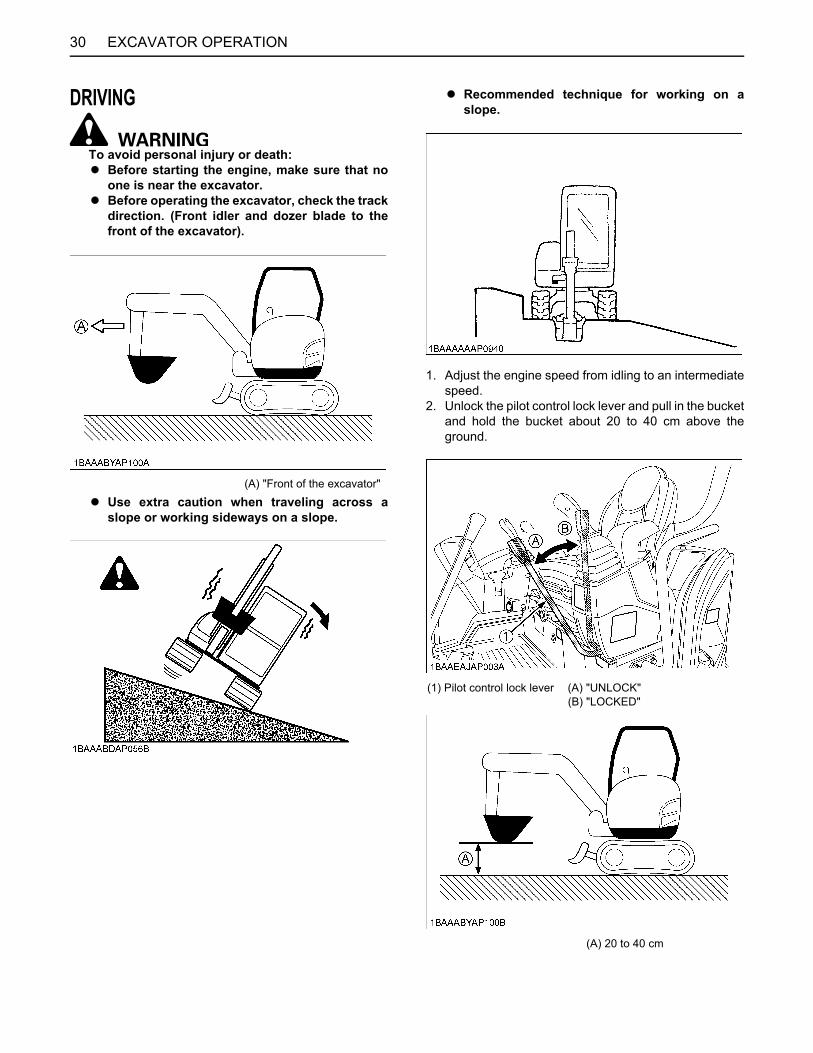
EXCAVATOR OPERATION30
DRIVING
To avoid personal injury or death:A Before starting the engine, make sure that no
one is near the excavator.A Before operating the excavator, check the track
direction. (Front idler and dozer blade to thefront of the excavator).
A Use extra caution when traveling across aslope or working sideways on a slope.
A Recommended technique for working on aslope.
1. Adjust the engine speed from idling to an intermediatespeed.
2. Unlock the pilot control lock lever and pull in the bucketand hold the bucket about 20 to 40 cm above theground.
(A) "Front of the excavator"
(1) Pilot control lock lever (A) "UNLOCK" (B) "LOCKED"
(A) 20 to 40 cm

31EXCAVATOR OPERATION
3. Activate the dozer control lever to raise the dozer.
BDrive Levers (Right,Left)
To avoid personal injury or death:A When driving the excavator keep the dozer
blade in front. To move the excavator forward,move the drive levers to (A) and to move inreverse, move the drive levers to (B) with dozerblade in front. If the dozer blade is behindoperator station, then the controls arereversed, moving the excavator forward willrequire (B) and moving the excavatorbackwards will require (A), but this is notrecommended.
Pushing the drive levers forward, moves the excavatorforwards, and vice-versa. The front of the excavator is theside where the dozer is located; the drive sprocket is in therear of the excavator.
TURNS
To avoid personal injury or death:A Do not change direction on steep slopes, or the
excavator could tip over.A Before changing direction, beware of people in
the work area.
BPivot Turn
A Movement as illustrated is done with the dozer bladein front of the operator.
C Change of Direction while Travelling1. While travelling forward, bring the left drive lever into
the neutral position;the excavator will turn in the direction of the arrow ofthe illustration below.
(1) Dozer control lever(2) Dozer
(A) "Raise" (B) "Lower"
(1) Drive lever (left)(2) Drive lever (right)
(A) "Forward"(B) "Backward"(C) "Straight"
(A) "Travelling forward" (N) "Neutral position"
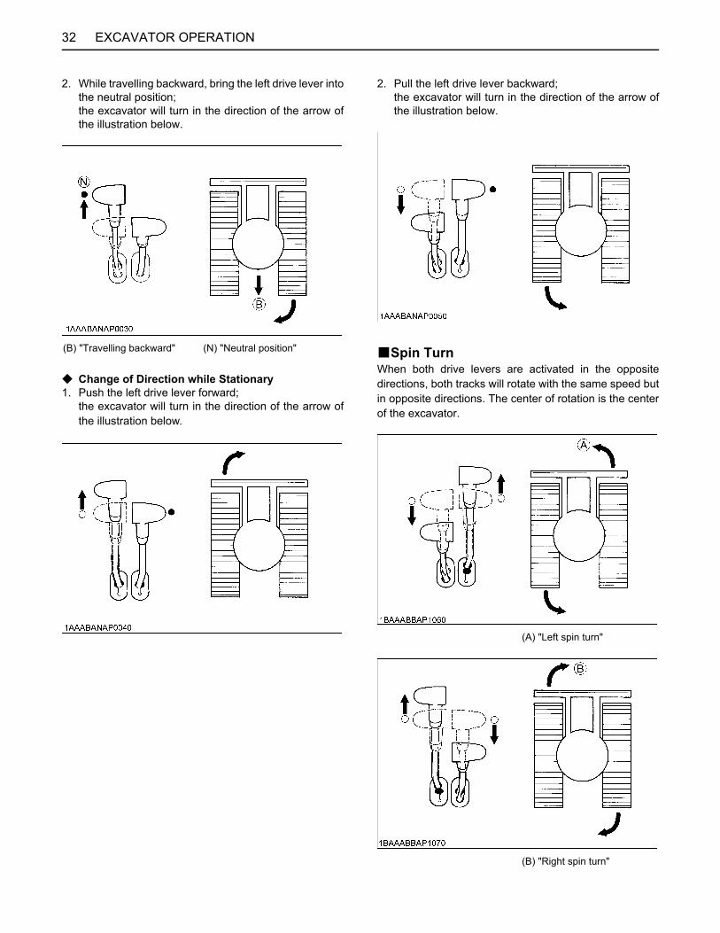
EXCAVATOR OPERATION32
2. While travelling backward, bring the left drive lever intothe neutral position;the excavator will turn in the direction of the arrow ofthe illustration below.
C Change of Direction while Stationary1. Push the left drive lever forward;
the excavator will turn in the direction of the arrow ofthe illustration below.
2. Pull the left drive lever backward;the excavator will turn in the direction of the arrow ofthe illustration below.
BSpin TurnWhen both drive levers are activated in the oppositedirections, both tracks will rotate with the same speed butin opposite directions. The center of rotation is the centerof the excavator.
(B) "Travelling backward" (N) "Neutral position"
(A) "Left spin turn"
(B) "Right spin turn"

33EXCAVATOR OPERATION
UP AND DOWNHILL DRIVING
To avoid personal injury or death:A When travelling up or down a slope, use extra
caution and follow the instructions below.
While traveling uphill, keep the lower edge of the bucketapprox. 20 to 40 cm above the ground. Although theKUBOTA excavator will not slip easily because of thetracks, it is safer to let the bucket slide over the groundwhile traveling downhill. Always choose slow speed foruphill and downhill traveling.
[UPHILL TRAVELING]
[DOWNHILL TRAVELING]
PARKING ON A SLOPE
To avoid personal injury or death:A When the excavator is parked or left
unattended on a slope, be sure to put thebucket on the ground and place all controllevers in neutral position, then brace the trackswith chocks.
OPERATION OF THE DOZER1. To raise the dozer, pull back the control lever. To lower
the dozer, push the control lever forward.
To float the dozer, push the control lever more forwardto the locked position.
2. While undertaking earth moving work, control bothdrive levers with the left hand and the dozer controllever with the right hand.
(A) 20 to 40 cm
(1) Chock
(1) Dozer control lever(2) Dozer
(A) "Raise"(B) "Lower"(C) "Float" (Locked position)

EXCAVATOR OPERATION34
TWO PATTERN SELECTION SYSTEM (TPSS)
To avoid personal injury or death:A Study control lever pattern A and pattern B.
Then choose the one which is most familiar.A Position the pattern selector lever (located on
the right side of operator's seat) in either thelower position (Pattern A) or the upper position(Pattern B).
A Engage the lever lock to prevent accidentalpattern change.
A Familiarize yourself with the pattern selectedby operating slowly.
BPattern ChangePosition the pattern selector lever to the desiredposition.
(1) Pattern selector lever (Two Pattern Selection System:TPSS)
(A) "Pattern A"(B) "Pattern B"
Lever Position
AttachmentControl Lever
(Left)
AttachmentControl Lever
(Right)
Pattern A
ABCD
Boom downBoom upSwing leftSwing right
Arm out (up)Arm in (crowd)Bucket crowdBucket dump
Pattern B
ABCD
Arm out (up)Arm in (crowd)Swing leftSwing right
Boom downBoom upBucket crowdBucket dump
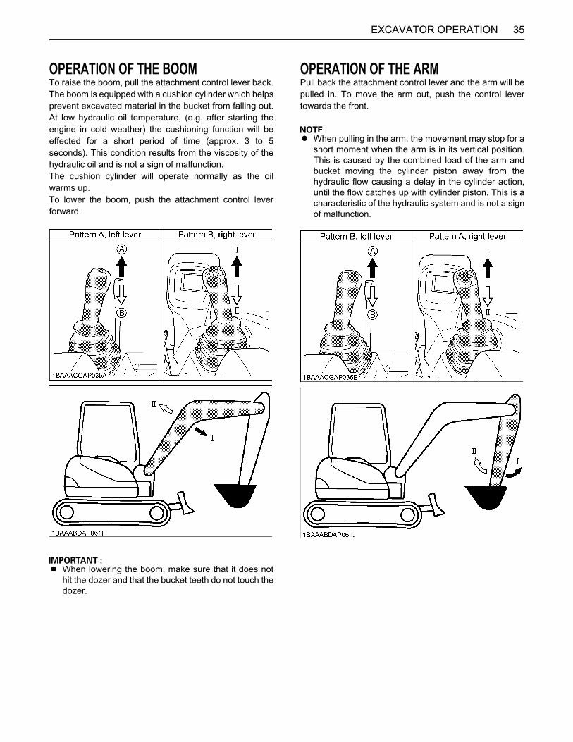
35EXCAVATOR OPERATION
OPERATION OF THE BOOMTo raise the boom, pull the attachment control lever back.The boom is equipped with a cushion cylinder which helpsprevent excavated material in the bucket from falling out.At low hydraulic oil temperature, (e.g. after starting theengine in cold weather) the cushioning function will beeffected for a short period of time (approx. 3 to 5seconds). This condition results from the viscosity of thehydraulic oil and is not a sign of malfunction. The cushion cylinder will operate normally as the oilwarms up.To lower the boom, push the attachment control leverforward.
A When lowering the boom, make sure that it does nothit the dozer and that the bucket teeth do not touch thedozer.
OPERATION OF THE ARMPull back the attachment control lever and the arm will bepulled in. To move the arm out, push the control levertowards the front.
A When pulling in the arm, the movement may stop for ashort moment when the arm is in its vertical position.This is caused by the combined load of the arm andbucket moving the cylinder piston away from thehydraulic flow causing a delay in the cylinder action,until the flow catches up with cylinder piston. This is acharacteristic of the hydraulic system and is not a signof malfunction.
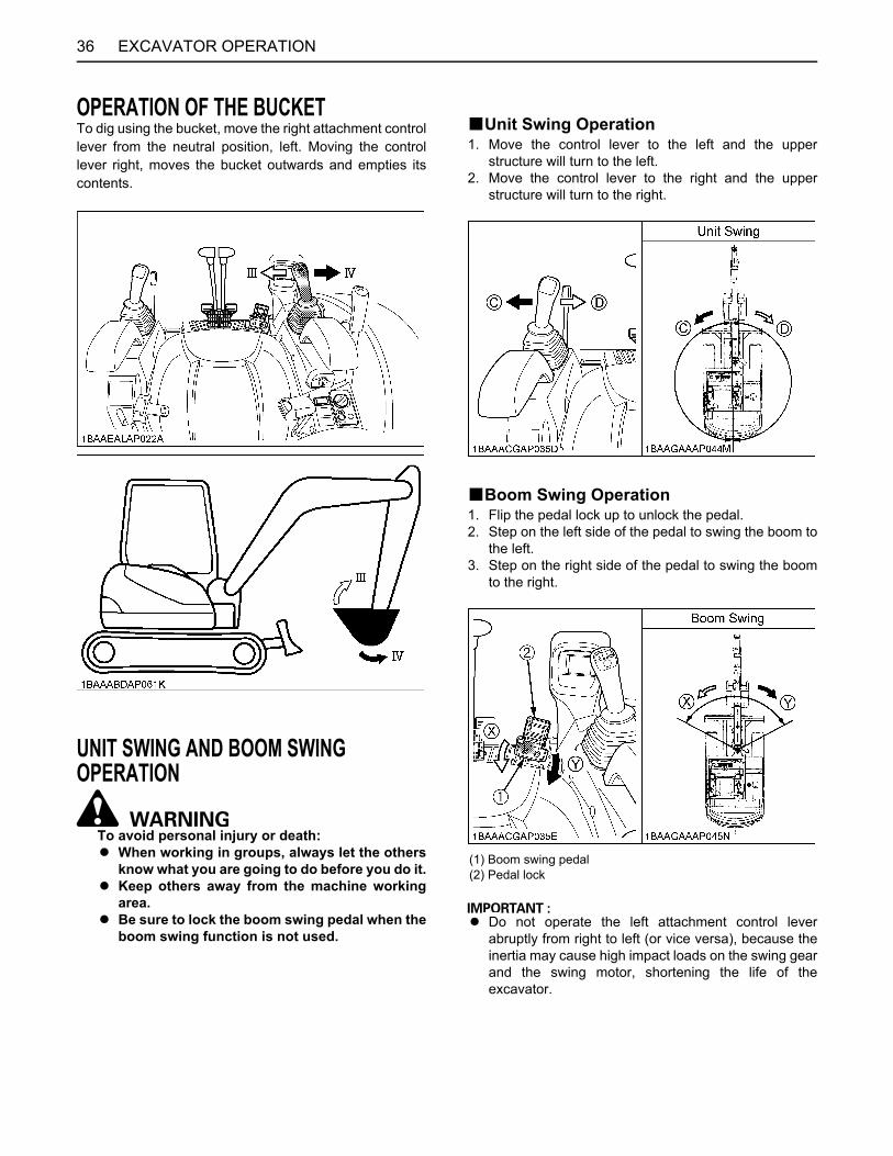
EXCAVATOR OPERATION36
OPERATION OF THE BUCKETTo dig using the bucket, move the right attachment controllever from the neutral position, left. Moving the controllever right, moves the bucket outwards and empties itscontents.
UNIT SWING AND BOOM SWING OPERATION
To avoid personal injury or death:A When working in groups, always let the others
know what you are going to do before you do it.A Keep others away from the machine working
area.A Be sure to lock the boom swing pedal when the
boom swing function is not used.
BUnit Swing Operation1. Move the control lever to the left and the upper
structure will turn to the left.2. Move the control lever to the right and the upper
structure will turn to the right.
BBoom Swing Operation1. Flip the pedal lock up to unlock the pedal.2. Step on the left side of the pedal to swing the boom to
the left.3. Step on the right side of the pedal to swing the boom
to the right.
A Do not operate the left attachment control leverabruptly from right to left (or vice versa), because theinertia may cause high impact loads on the swing gearand the swing motor, shortening the life of theexcavator.
(1) Boom swing pedal(2) Pedal lock
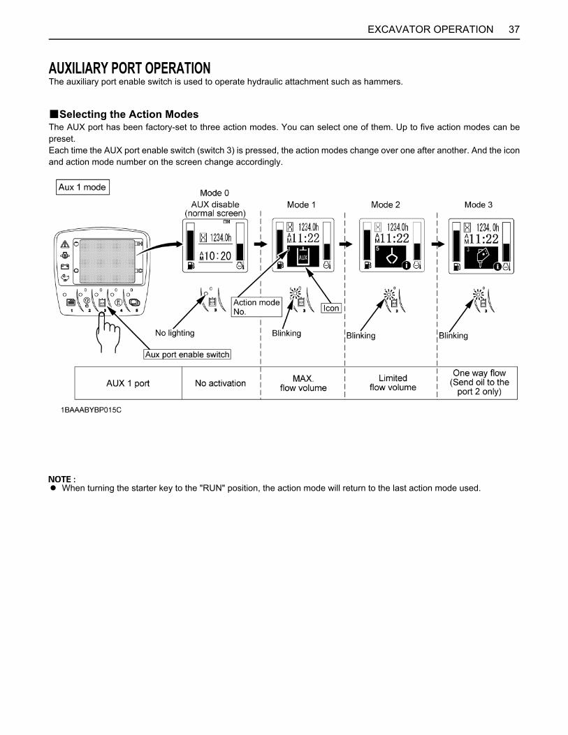
37EXCAVATOR OPERATION
AUXILIARY PORT OPERATIONThe auxiliary port enable switch is used to operate hydraulic attachment such as hammers.
BSelecting the Action ModesThe AUX port has been factory-set to three action modes. You can select one of them. Up to five action modes can bepreset.Each time the AUX port enable switch (switch 3) is pressed, the action modes change over one after another. And the iconand action mode number on the screen change accordingly.
A When turning the starter key to the "RUN" position, the action mode will return to the last action mode used.

EXCAVATOR OPERATION38
C Checking the settings of each action modeWhen an action mode is selected and the " " markappears at the lower right of the icon, the flow volumesetting gets displayed by pressing the switch 4.
[Display in AUX 1 modes]
BAUX Port Handling Procedure1. Turn the starter key to the "RUN" position.
Let the engine warm up after start-up for approx. 10minutes under no load conditions.
2. Lower the pilot control lock lever (UNLOCK).
(1) Icon(2) Information mark(3) Information switch (Switch 4)
(1) AUX Port 1(2) AUX Port 2
(1) Starter switch (A) "STOP"(B) "RUN"(C) "START"
(1) Pilot control lock lever (A) "UNLOCK"(B) "LOCKED"
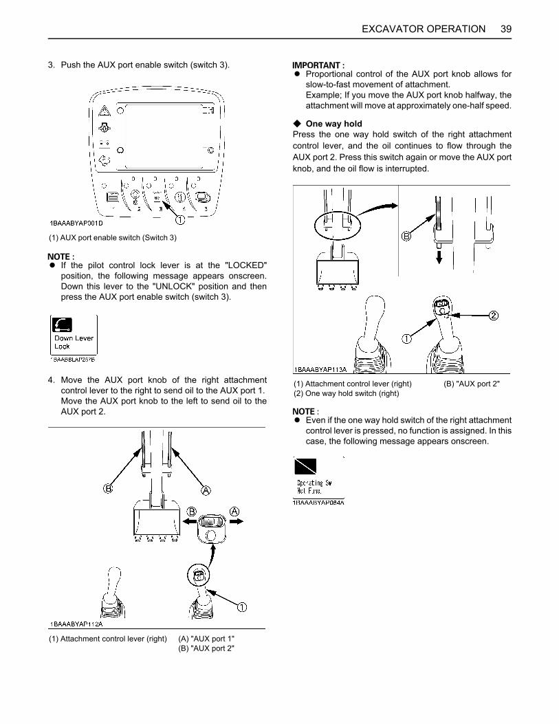
39EXCAVATOR OPERATION
3. Push the AUX port enable switch (switch 3).
A If the pilot control lock lever is at the "LOCKED"position, the following message appears onscreen.Down this lever to the "UNLOCK" position and thenpress the AUX port enable switch (switch 3).
4. Move the AUX port knob of the right attachmentcontrol lever to the right to send oil to the AUX port 1.Move the AUX port knob to the left to send oil to theAUX port 2.
A Proportional control of the AUX port knob allows forslow-to-fast movement of attachment.Example; If you move the AUX port knob halfway, theattachment will move at approximately one-half speed.
C One way holdPress the one way hold switch of the right attachmentcontrol lever, and the oil continues to flow through theAUX port 2. Press this switch again or move the AUX portknob, and the oil flow is interrupted.
A Even if the one way hold switch of the right attachmentcontrol lever is pressed, no function is assigned. In thiscase, the following message appears onscreen.
(1) AUX port enable switch (Switch 3)
(1) Attachment control lever (right) (A) "AUX port 1"(B) "AUX port 2"
(1) Attachment control lever (right)(2) One way hold switch (right)
(B) "AUX port 2"
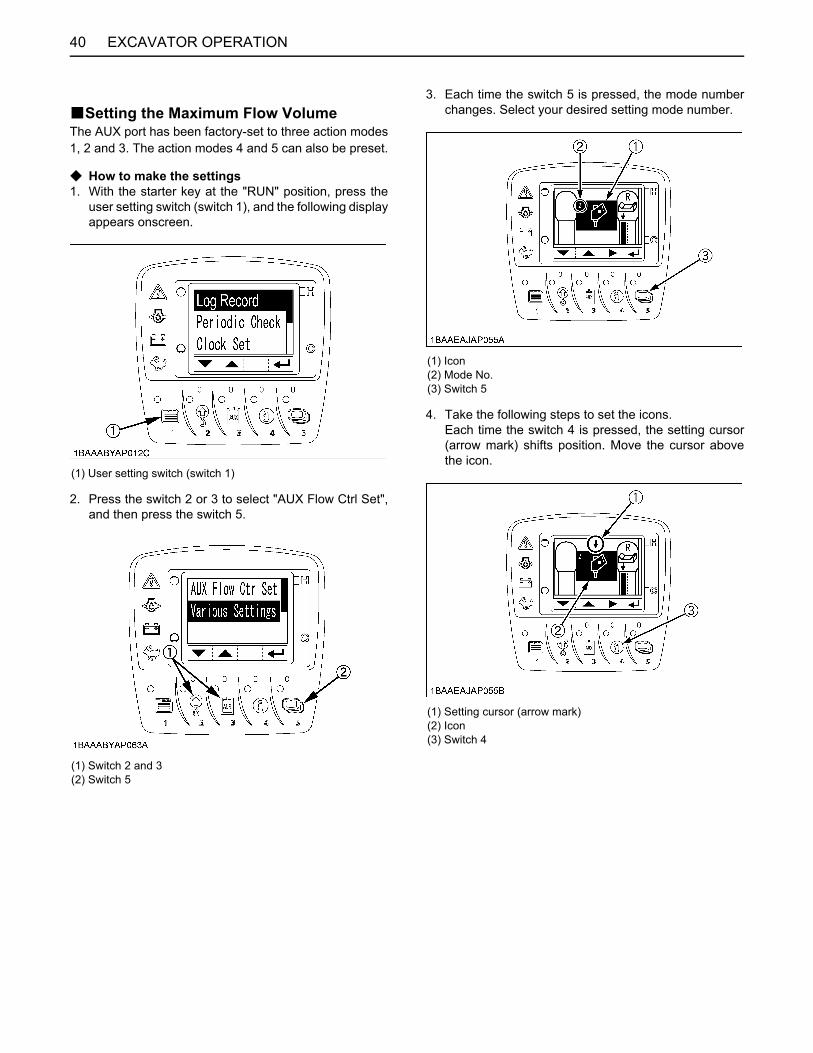
EXCAVATOR OPERATION40
BSetting the Maximum Flow VolumeThe AUX port has been factory-set to three action modes1, 2 and 3. The action modes 4 and 5 can also be preset.
C How to make the settings1. With the starter key at the "RUN" position, press the
user setting switch (switch 1), and the following displayappears onscreen.
2. Press the switch 2 or 3 to select "AUX Flow Ctrl Set",and then press the switch 5.
3. Each time the switch 5 is pressed, the mode numberchanges. Select your desired setting mode number.
4. Take the following steps to set the icons.Each time the switch 4 is pressed, the setting cursor(arrow mark) shifts position. Move the cursor abovethe icon.
(1) User setting switch (switch 1)
(1) Switch 2 and 3(2) Switch 5
(1) Icon(2) Mode No.(3) Switch 5
(1) Setting cursor (arrow mark)(2) Icon(3) Switch 4

41EXCAVATOR OPERATION
5. Each time the switch 2 or 3 is pressed, the iconchanges. Select your desired icons.
C Types of AUX icons
A There is no relationship between the icons and theflow control settings. Select icons to suit the images ofattachments to be connected.
A In an action mode with the disable icon preset, suchaction mode is skipped even if selected.
Take an example of the following settings: AUX (standard) icon for action mode 1, Breaker icon for action mode 2,Disable icon for actions modes 3, 4 and 5.
Each time the AUX port enable switch (switch 3) ispressed, the display changes from action mode 1,action mode 2 to normal mode in this order.
[Setting example]
(1) Switch 2(2) Switch 3(3) Icon
(1) AUX (Standard)(2) Brush cutter(3) Rotary grapple(4) Grapple(5) Auger
(6) Clamshell(7) Breaker(8) Tilt bucket(9) Thumb(10) Blank (disable)
(A) Blank (disable) icon

EXCAVATOR OPERATION42
6. Set the maximum flow volume for each AUX port.Press the switch 4 to move the setting cursor (arrowmark) to the port 2 position of Thumb port at the right.
7. Press the switch 2 or 3 to preset the maximum flowvolume.Set the bar to the highest level, and the flow volumewill be maximized.Set the bar to the lowest level (no bar displayed), andthere will be no oil flow.Then press the switch 4 to go to the next port, andmake the settings for all the other ports.
A Some attachments might not be activated even whenthe bar level is still somewhat above the lowestposition. Or even when the bars of ports 1 and 2 areat the same level, the same speed might not beachieved. This does not indicate a machine problem,however. Readjust the bar to the optimum levelaccording to your attachment manual.
A Suppose that the same attachment is mounted onanother machine. Even if the same flow control settingis made, the same speed cannot be achieved. Makean optimum setting on each machine.
(1) Setting cursor (arrow)(2) Switch 4
(1) AUX 1 (A) "AUX port 1"(B) "AUX port 2"
(1) Switch 2 (Lower flow volume)(2) Switch 3 (Higher flow volume)(3) Switch 4
(A) "MAX. flow volume"(B) "Output interrupted"

43EXCAVATOR OPERATION
8. Go back to Step 3 to make settings for the next actionmode. When all the settings of all the action modeshave been made, press the switch 1 to return to thenormal screen.
C BUAUX port MAX. Flow volume
A When the AUX port is not used for a long period, dirtparticles can settle in the lower part of the AUX portlines. When the plugs on the AUX port lines areremoved to connect attachments, drain approx. 100 cc(3.4 oz) of oil before making connections.
(1) Switch 1
AUX 1 port
MAX. flow volume(Theoretical L/min) 60.5
MAX. pressureMPa (kgf/cm )
17.2(175)
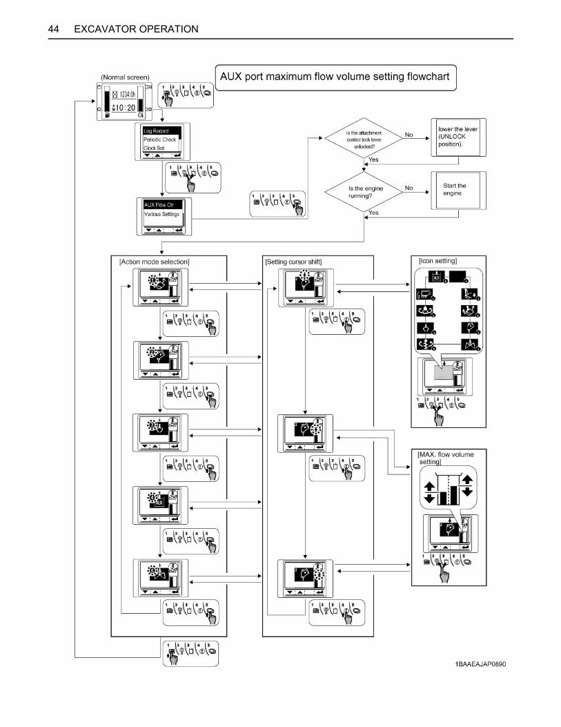
44 EXCAVATOR OPERATION

45EXCAVATOR OPERATION
HOW TO RELEASE PRESSURE TRAPPED IN THE HYDRAULIC SYSTEM
To avoid personal injury or death:A Relieve residual hydraulic pressure
immediately after the engine has stopped.
1. Lower the attachments and the blade down to theground.
2. Turn the key to "STOP" position and shut off theengine.
3. After stopping the engine, turn the key to "RUN"position.
4. Set the pilot control lock lever to "UNLOCK" position.
5. Move the operating lever to release pressure in thehydraulic system.
[How to release pressure trapped in the AUX port]1. Perform the above operations of 1 to 4.2. Turn "ON" the AUX port enable switch.
3. Make sure that the flow volume in all the AUX ports isnot minimized.If the pressure is removed after minimizing the flowvolume in the AUX port, release pressure is notremoved completely and the hose coupler may beunable to connect and disconnect.
(1) Pilot control lock lever(2) Attachment control lever (left)
(A) "UNLOCK"(B) "LOCKED"
(1) AUX port enable switch (Switch 3)
(1) Flow volume in AUX port display
(A) Flow volume in AUX port(B) Maximum(C) Minimum
(B) Maximum status of flow volume in AUX port(C) Minimum status of flow volume in AUX port

EXCAVATOR OPERATION46
4. Move the AUX port knob mounted to the operatinglever to the right to release pressure in the AUX port.
1-way or 2-way CIRCUIT SELECTION VALVE OPERATIONA selection valve which selects 1-way or 2-way circuit ofservice port has been installed on the hydraulic tank.1. When equipment which needs a 1-way circuit will be
used, position the arrow, by using the selector lever,on the axis of the selection valve to the 1-way circuitposition, to reduce the back pressure.
2. When equipment which needs a 2-way circuit will beused, position the arrow on the axis of the selectionvalve to the 2-way circuit position.
(1) AUX port knob(2) Attachment control lever (right)
A 1-way circuit.....A 2-way circuit.....
HAMMER etc.THUMB, TILT BUCKET,AUGER, GRAPPLE etc.
(1) Selection valve(2) Selector lever
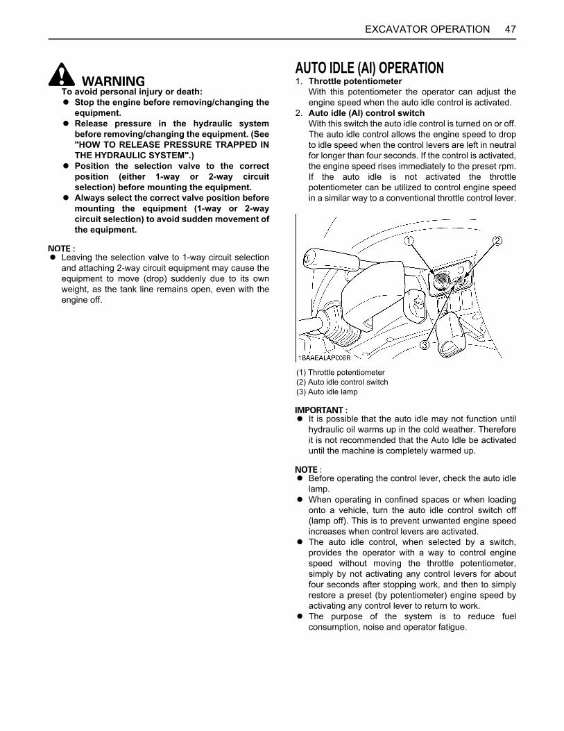
47EXCAVATOR OPERATION
To avoid personal injury or death:A Stop the engine before removing/changing the
equipment.A Release pressure in the hydraulic system
before removing/changing the equipment. (See"HOW TO RELEASE PRESSURE TRAPPED INTHE HYDRAULIC SYSTEM".)
A Position the selection valve to the correctposition (either 1-way or 2-way circuitselection) before mounting the equipment.
A Always select the correct valve position beforemounting the equipment (1-way or 2-waycircuit selection) to avoid sudden movement ofthe equipment.
A Leaving the selection valve to 1-way circuit selectionand attaching 2-way circuit equipment may cause theequipment to move (drop) suddenly due to its ownweight, as the tank line remains open, even with theengine off.
AUTO IDLE (AI) OPERATION1. Throttle potentiometer
With this potentiometer the operator can adjust theengine speed when the auto idle control is activated.
2. Auto idle (AI) control switchWith this switch the auto idle control is turned on or off.The auto idle control allows the engine speed to dropto idle speed when the control levers are left in neutralfor longer than four seconds. If the control is activated,the engine speed rises immediately to the preset rpm.If the auto idle is not activated the throttlepotentiometer can be utilized to control engine speedin a similar way to a conventional throttle control lever.
A It is possible that the auto idle may not function untilhydraulic oil warms up in the cold weather. Thereforeit is not recommended that the Auto Idle be activateduntil the machine is completely warmed up.
A Before operating the control lever, check the auto idlelamp.
A When operating in confined spaces or when loadingonto a vehicle, turn the auto idle control switch off(lamp off). This is to prevent unwanted engine speedincreases when control levers are activated.
A The auto idle control, when selected by a switch,provides the operator with a way to control enginespeed without moving the throttle potentiometer,simply by not activating any control levers for aboutfour seconds after stopping work, and then to simplyrestore a preset (by potentiometer) engine speed byactivating any control lever to return to work.
A The purpose of the system is to reduce fuelconsumption, noise and operator fatigue.
(1) Throttle potentiometer(2) Auto idle control switch(3) Auto idle lamp
EXCAVATOR OPERATION48
IMPORTANT INFORMATION ON EXCAVATOR OPERATIONA Do not try to crush concrete or boulders using side
swings with the bucket. Also avoid using side sweepsof the bucket to move earth piles.
A Under all circumstances avoid the followingoperations:A Excavation using the gravitational impact of the
machine.A Compacting of gravel or soil using the dropping
action of the bucket.A Excavation using the traveling power of the
machine.A Do not try to drop or shake off soil adhering to the
bucket in the manner given in the points below. Thiscan cause damage to the machine.Adhering soil can be shaken off when the bucket isbeing emptied by moving the bucket out to themaximum stroke of the cylinder. Should this notsuffice, swing out the arm as far as possible andoperate the bucket back and forth.
A Do not hit the dozer with the boom cylinder!Make sure that the boom cylinder does not hit thedozer when doing deep excavation. If necessaryswing around so that the dozer is in the back of themachine.
A Pay attention when pulling in the bucket!When pulling in the bucket (for driving ortransportation) avoid hitting the dozer.
A Avoid collisions!When moving the excavator, pay attention that thedozer does not collide with obstructions such asboulders, etc.Such collisions shorten the life of the dozer and thecylinder substantially.
A Support the machine correctly!When stabilizing the machine with the dozer, lower thedozer to engage the full width on the ground.
A If the water or mud level reaches higher than the top ofthe tracks, the swivel bearing, swivel motor gear andring gear may be exposed to mud, water and otherforeign objects.The excavator must be properly pressure washedafter each use.A Thoroughly clean the area around the swivel
bearing, swivel motor gear and ring gear to removeforeign objects.
A Inspect the swivel motor oil sump (if equipped) forwater contamination. If water is present, refer tooperator's manual for lubricant replacementprocedure.
A Refer to operator's manual for proper swivelbearing, swivel motor gear and ring gearlubrication procedures.
A Reinstall any protective covering if removedearlier.
A Avoid applying excessive load with cylinders fullyextended, or the machine easily gets damaged.
A Relieve residual hydraulic pressure immediatelyafter the engine has stopped.
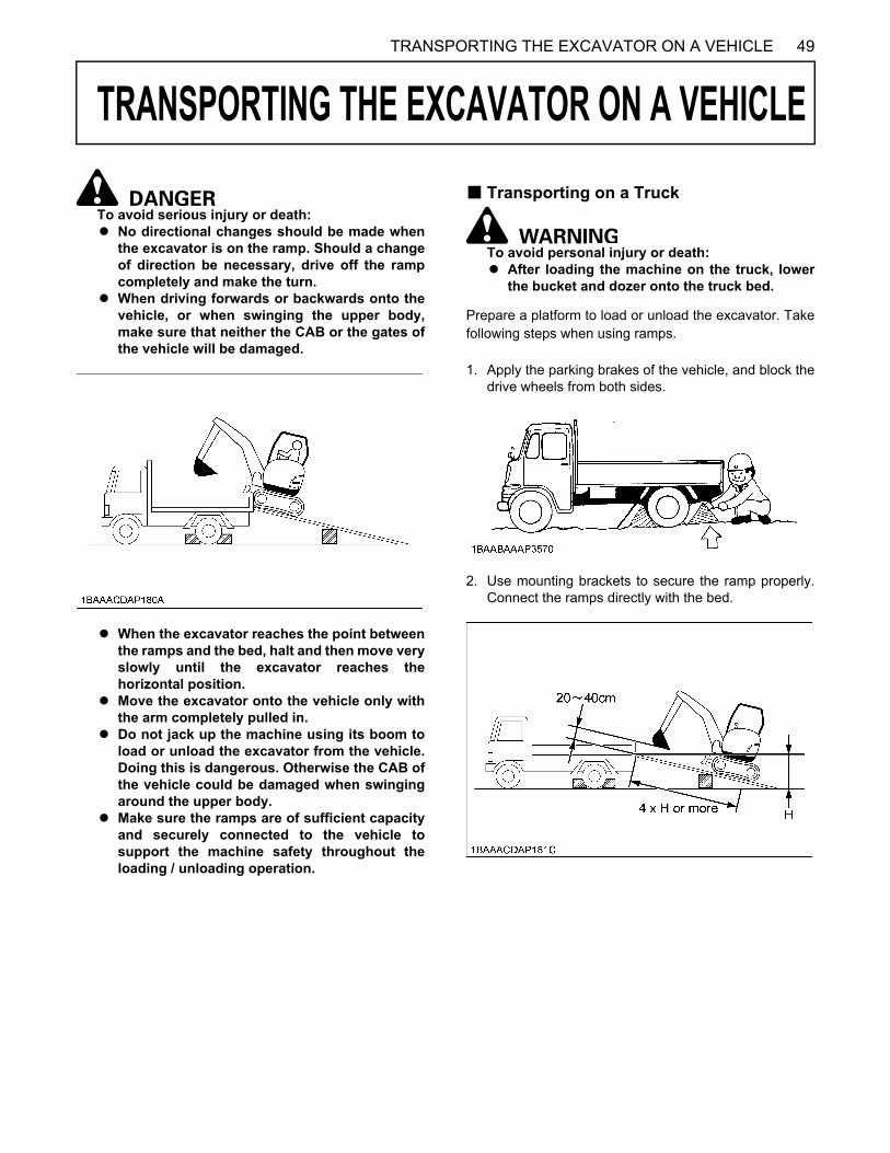
49TRANSPORTING THE EXCAVATOR ON A VEHICLE
TRANSPORTING THE EXCAVATOR ON A VEHICLE
To avoid serious injury or death: A No directional changes should be made when
the excavator is on the ramp. Should a changeof direction be necessary, drive off the rampcompletely and make the turn.
A When driving forwards or backwards onto thevehicle, or when swinging the upper body,make sure that neither the CAB or the gates ofthe vehicle will be damaged.
A When the excavator reaches the point betweenthe ramps and the bed, halt and then move veryslowly until the excavator reaches thehorizontal position.
A Move the excavator onto the vehicle only withthe arm completely pulled in.
A Do not jack up the machine using its boom toload or unload the excavator from the vehicle.Doing this is dangerous. Otherwise the CAB ofthe vehicle could be damaged when swingingaround the upper body.
A Make sure the ramps are of sufficient capacityand securely connected to the vehicle tosupport the machine safety throughout theloading / unloading operation.
B Transporting on a Truck
To avoid personal injury or death:A After loading the machine on the truck, lower
the bucket and dozer onto the truck bed.
Prepare a platform to load or unload the excavator. Takefollowing steps when using ramps.
1. Apply the parking brakes of the vehicle, and block thedrive wheels from both sides.
2. Use mounting brackets to secure the ramp properly.Connect the ramps directly with the bed.

TRANSPORTING THE EXCAVATOR ON A VEHICLE50
3. For additional safety, use blocks or supports under theramps and the bed.
4. Completely align the ramps and the tracks and thendrive the excavator slowly up the ramps. Afterensuring that the tracks are completely on the bed,swing the upper body around to the back of thevehicle.
5. Lower the dozer onto the bed.6. Pull in the bucket and arm completely. Then lower the
boom.7. Stop the engine, release pressure trapped in the
hydraulic system and remove the key.8. Raise the pilot control lock lever.9. Block the tracks with blocks and tie down the
excavator.
B Towing the machine
To avoid personal injury or death:A When towing the excavator or pulling a load
must be less than the strength of the towingline attached to excavator. Not to be used fortie-down or lifting the machine.
A Towing is only allowed over a short distanceand at walking speed.
1. Attach the tow bar or towing rope to the hook on theexcavator and to the pulling vehicle. The tow barshould be mounted at a right angle to the vehicles.
2. The operator must be seated during the recoveryprocedure.
3. Drive slowly with the tractive vehicle to avoid abruptloads.
(A) Tie down point
(1) Chain(2) Block
(1) Tow line
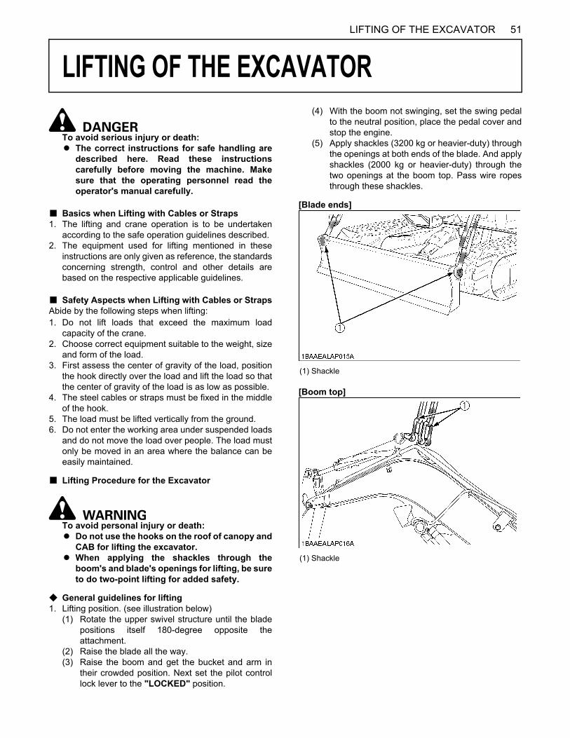
51LIFTING OF THE EXCAVATOR
LIFTING OF THE EXCAVATOR
To avoid serious injury or death:A The correct instructions for safe handling are
described here. Read these instructionscarefully before moving the machine. Makesure that the operating personnel read theoperator's manual carefully.
B Basics when Lifting with Cables or Straps1. The lifting and crane operation is to be undertaken
according to the safe operation guidelines described.2. The equipment used for lifting mentioned in these
instructions are only given as reference, the standardsconcerning strength, control and other details arebased on the respective applicable guidelines.
B Safety Aspects when Lifting with Cables or StrapsAbide by the following steps when lifting:1. Do not lift loads that exceed the maximum load
capacity of the crane.2. Choose correct equipment suitable to the weight, size
and form of the load.3. First assess the center of gravity of the load, position
the hook directly over the load and lift the load so thatthe center of gravity of the load is as low as possible.
4. The steel cables or straps must be fixed in the middleof the hook.
5. The load must be lifted vertically from the ground. 6. Do not enter the working area under suspended loads
and do not move the load over people. The load mustonly be moved in an area where the balance can beeasily maintained.
B Lifting Procedure for the Excavator
To avoid personal injury or death:A Do not use the hooks on the roof of canopy and
CAB for lifting the excavator.A When applying the shackles through the
boom's and blade's openings for lifting, be sureto do two-point lifting for added safety.
C General guidelines for lifting 1. Lifting position. (see illustration below)
(1) Rotate the upper swivel structure until the bladepositions itself 180-degree opposite theattachment.
(2) Raise the blade all the way.(3) Raise the boom and get the bucket and arm in
their crowded position. Next set the pilot controllock lever to the "LOCKED" position.
(4) With the boom not swinging, set the swing pedalto the neutral position, place the pedal cover andstop the engine.
(5) Apply shackles (3200 kg or heavier-duty) throughthe openings at both ends of the blade. And applyshackles (2000 kg or heavier-duty) through thetwo openings at the boom top. Pass wire ropesthrough these shackles.
[Blade ends]
[Boom top]
(1) Shackle
(1) Shackle

LIFTING OF THE EXCAVATOR52
2. Attaching the steel cables or straps.(1) Always hook the excavator at three points. (one
on the boom and left and right of the dozer)(2) Always use a shackle on each lifting hole when
attaching the cables or straps.(3) Keep the angle between the front and rear cables
or straps within 49 .
A While lifting, carefully keep the machine well balancedwith its center of gravity in mind.
A Do not lift the machine with the boom swinging or theupper structure swiveling.
3. TackleThe weights of the excavators and the recommendedtackle for lifting these loads are mentioned in thefollowing table. Choose components having enoughstrength.
*Excavator Weight: With CAB, steel tracks. Steel wire: 6X24
4. Lifting(1) Lift slowly and safely(2) Do not enter the excavator area when lifting.(3) Lift the excavator horizontally. (Modify cable or
strap connections according to needs)Maximum strengthfor example : (JIS G 35 25) - "6 x24"
(1) Cable or strap (A) 49 or less
Excavator Weight*CAB CANOPY
3835 kg 3685 kg
Load / Cable 12219 N
Minimum Wire Diameter(Safety factor=6) 14 mm or more
Diameter zinc-plated not zinc-plated
10 mm (3/8) 45.8 KN 49.3 KN
12.5 mm (1/2) 71.5 KN 77 KN
14 mm (9/16) 89.7 KN 96.6 KN
16 mm (5/8) 117 KN 126 KN
18 mm (45/64) 148 KN 160 KN

53MAINTENANCE
MAINTENANCE
MAINTENANCE INTERVALSNo. Check points MeasuresHour meter indicator
Interval Ref.page50 100 150 200 250 300 350 400 450
1 Coolantcheck Daily check 58
change every 2 years 75
2 Fuel check Daily check 58
3 Engine oilcheck Daily check 59
change every 250 hrs 70
4 Hydraulic oilcheck Daily check 59
change every 1000 hrs 73 *1
5 Grease front attachments
Bucket and bucket link pin - Daily check 61
Boom swing fulcrum - Daily check 62
Others - Daily check 61
6 Radiator and oil cooler check Daily check 60
7 Washer liquid check Daily check 61
8 Engine and electrical wiring check Daily check 61
9 Fuel tank, Water separator drain every 50 hrs 63,63
10 Battery condition check every 50 hrs 64
11 Greasing swing bearing teeth - every 50 hrs 65
12 V-belt tension
check Daily check 60
adjust every 200 hrs 66
replace every 500 hrs 72
13 Radiator hoses and clampscheck every 200 hrs 67
replace every 2 years 75
14 Air filter element
Outer elementclean every 200 hrs 67 *2
@replace every 1000 hrs 74 *2
Inner element replace every 1000 hrs 74 *2
15 Greasing swing ball bearing - every 200 hrs 67
16 Fuel filter cartridge replace every 500 hrs 71 @
17 Engine oil filter replace every 250 hrs 70
18 Drive unit oil change every 500 hrs 71
19 Breather filter replace every 500 hrs 72
20 Hydraulic return filter element replace every 500 hrs 72
21 Hydraulic suction filter element replace every 1000 hrs 73
22 Filter in the pilot hydraulic system replace every 1000 hrs 72
23 Fuel injection nozzle injection pressure check every 1500 hrs 74 *4 @
24 Front idler and track roller oil change every 2000 hrs 74
25 Alternator and starter motor check every 2000 hrs 74
26 Injection pump check every 3000 hrs 74 *4 @
27 Radiator system rinse every 2 years 75
28 Fuel line and Intake air linecheck every 200 hrs 68
@replace every 2 years 77 *3
D 500 thru 1000 continued to the following table.

54 MAINTENANCE
No. Check points MeasuresHour meter indicator
Interval Ref.page500 550 600 650 700 750 800 1000
1 Coolantcheck Daily check 58
change every 2 years 75
2 Fuel check Daily check 58
3 Engine oilcheck Daily check 59
change every 250 hrs 70
4 Hydraulic oilcheck Daily check 59
change every 1000 hrs 73 *1
5 Grease front attachments
Bucket and bucket link pin - Daily check 61
Boom swing fulcrum - Daily check 62
Others - Daily check 61
6 Radiator and oil cooler check Daily check 60
7 Washer liquid check Daily check 61
8 Engine and electrical wiring check Daily check 61
9 Fuel tank, Water separator drain every 50 hrs 63,63
10 Battery condition check every 50 hrs 64
11 Greasing swing bearing teeth - every 50 hrs 65
12 V-belt tension
check Daily check 60
adjust every 200 hrs 66
replace every 500 hrs 72
13 Radiator hoses and clampscheck every 200 hrs 67
replace every 2 years 75
14 Air filter element
Outer elementclean every 200 hrs 67 *2
@replace every 1000 hrs 74 *2
Inner element replace every 1000 hrs 74 *2
15 Greasing swing ball bearing - every 200 hrs 67
16 Fuel filter cartridge replace every 500 hrs 71 @
17 Engine oil filter replace every 250 hrs 70
18 Drive unit oil change every 500 hrs 71
19 Breather filter replace every 500 hrs 72
20 Hydraulic return filter element replace every 500 hrs 72
21 Hydraulic suction filter element replace every 1000 hrs 73
22 Filter in the pilot hydraulic system replace every 1000 hrs 72
23 Fuel injection nozzle injection pressure check every 1500 hrs 74 *4 @
24 Front idler and track roller oil change every 2000 hrs 74
25 Alternator and starter motor check every 2000 hrs 74
26 Injection pump check every 3000 hrs 74 *4 @
27 Radiator system rinse every 2 years 75
28 Fuel line and Intake air linecheck every 200 hrs 68
@replace every 2 years 77 *3

55MAINTENANCE
C Air-conditioner
First operation*1 When using a hydraulic hammer, change hydraulic oil and return filter according to the table on "Hydraulic OilChange (Including Exchange of the Suction Filter in the Hydraulic Tank) under "EVERY 1000 SERVICE HOURS" in thechapter "REGULAR CHECKS AND MAINTENANCE WORK".*2 Clean and replace the air filter more frequently if used under dusty conditions. When the filter is very dirty from dustyconditions, replace the filter. *3 Replace only if necessary. *4 Consult your local KUBOTA dealer for this service.A The items listed above (@ marked) are registered as emission related critical parts by KUBOTA in the U.S.EPA non-
road emission regulation. As the engine owner, you are responsible for the performance of the requiredmaintenance on the engine according to the above instruction. Please see the warranty Statement in detail.
No. Check points MeasuresHour meter indicator
Interval Ref.page50 100 150 200 250 300 350 400 450
1 Air filterclean every 200 hrs 69 *2
replace every 1000 hrs - *2
2 Air conditioner condenser clean every 200 hrs 69
3 Air conditioner pipes and hosescheck every 1 year 75
replace every 2 years 75
4 Refrigerant (gas) check service as required 77
No. Check points MeasuresHour meter indicator
Interval Ref.page500 550 600 650 700 750 800 1000
1 Air filterclean every 200 hrs 69 *2
replace every 1000 hrs - *2
2 Air conditioner condenser clean every 200 hrs 69
3 Air conditioner pipes and hosescheck every 1 year 75
replace every 2 years 75
4 Refrigerant (gas) check service as required 77
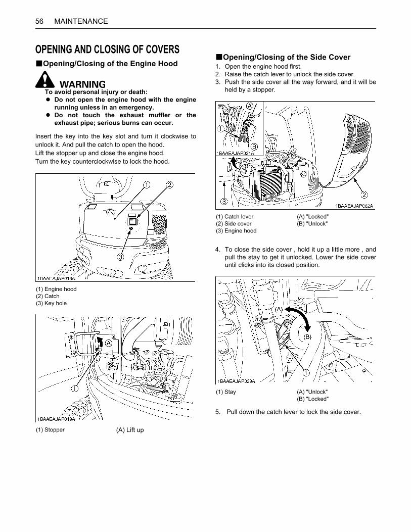
MAINTENANCE56
OPENING AND CLOSING OF COVERSBOpening/Closing of the Engine Hood
To avoid personal injury or death:A Do not open the engine hood with the engine
running unless in an emergency.A Do not touch the exhaust muffler or the
exhaust pipe; serious burns can occur.
Insert the key into the key slot and turn it clockwise tounlock it. And pull the catch to open the hood.Lift the stopper up and close the engine hood.Turn the key counterclockwise to lock the hood.
BOpening/Closing of the Side Cover1. Open the engine hood first.2. Raise the catch lever to unlock the side cover.3. Push the side cover all the way forward, and it will be
held by a stopper.
4. To close the side cover , hold it up a little more , andpull the stay to get it unlocked. Lower the side coveruntil clicks into its closed position.
5. Pull down the catch lever to lock the side cover.
(1) Engine hood(2) Catch(3) Key hole
(1) Stopper (A) Lift up
(1) Catch lever(2) Side cover(3) Engine hood
(A) "Locked"(B) "Unlock"
(1) Stay (A) "Unlock"(B) "Locked"

57MAINTENANCE
BWhere to store the Tool[CANOPY type]The tool box is located under the seat.
[CAB type]The tool box is located under the CAB door.
BCup Holder
BWhere to store the Grease Gun[CANOPY type]
The grease gun is located under the seat.
[CAB type]The grease gun is located under the CAB door.
BWhere to keep Operator's Manual
(1) Box for storage
(1) Box for storage
(1) Cup holder
(1) Grease gun
(1) Cover (2) Grease gun
(1) Operator's manual storage (2) Rear cover

MAINTENANCE58
DAILY CHECKS
To avoid personal injury or death:A When operating, keep hands and body inside
of the ROPS / OPG (Top Guard Level I)protective envelope.
A Do not touch the control levers and the pedalsfrom outside the cab while the engine isrunning.
For your own safety and to assure the long life of yourmachine, a careful check should be made before eachoperation.
BChecking Coolant Level
To avoid personal injury or death:A Move the excavator to even ground.A Make sure that the engine is turned off.A Do not open the radiator cap right after the
engine has been stopped; Serious burns canoccur from contact with escaping hot coolantfluid.
A Check the coolant level in the recovery tankonly after the engine has cooled down.
A Remove the radiator cap only if absolutelynecessary.
The radiator has a recovery tank. Should the coolant levelin the radiator sink, the water will be automatically beforwarded to the radiator.Open the side cover. (See "Opening / Closing of the SideCover" in "OPENING AND CLOSING OF COVERS"section.)Check the coolant level in the recovery tank and fill up ifnecessary. The coolant level should be between themarks "FULL" and "LOW".
A Do not fill the recovery tank over the "FULL" marking.A Do not fill with dirty or salty water.
BChecking Fuel Level
To avoid personal injury or death:A Stop the engine and remove the key before fuelling.A Do not smoke while fuelling.
A By temperatures over -5 , use No.2-D diesel fuel,when temperatures are below -5 , use No.1-D dieselfuel.
A Make sure that the fuel tank is not run empty. Air willenter the fuel system, and must be purged beforerestarting.
A See "PURGING OF THE FUEL SYSTEM" in "OTHERADJUSTMENTS AND REPLACEMENTS" section.
A To prevent condensation (water) accumulations in thefuel tank, fill the fuel into the tank before parkingovernight.
1. Turn the starter key to the position "RUN".
A Even with the starter key not yet inserted, press theelectronic meter's user setting switch or the displayselector switch, and the LCD shows the hour meter,fuel gauge, water temperature gauge and clock for 10seconds.
2. Check the fuel level by the fuel level indicator.
3. If necessary, open the cap and fill in fuel. (See "LCDfor Normal Operation" in "CHECK BEFORE START"section.)
(1) Recovery tank (A) "FULL" (B) "LOW"
(1) Fuel gauge (A) "EMPTY"(B) "FULL"
Fuel tank capacity 45.1 L
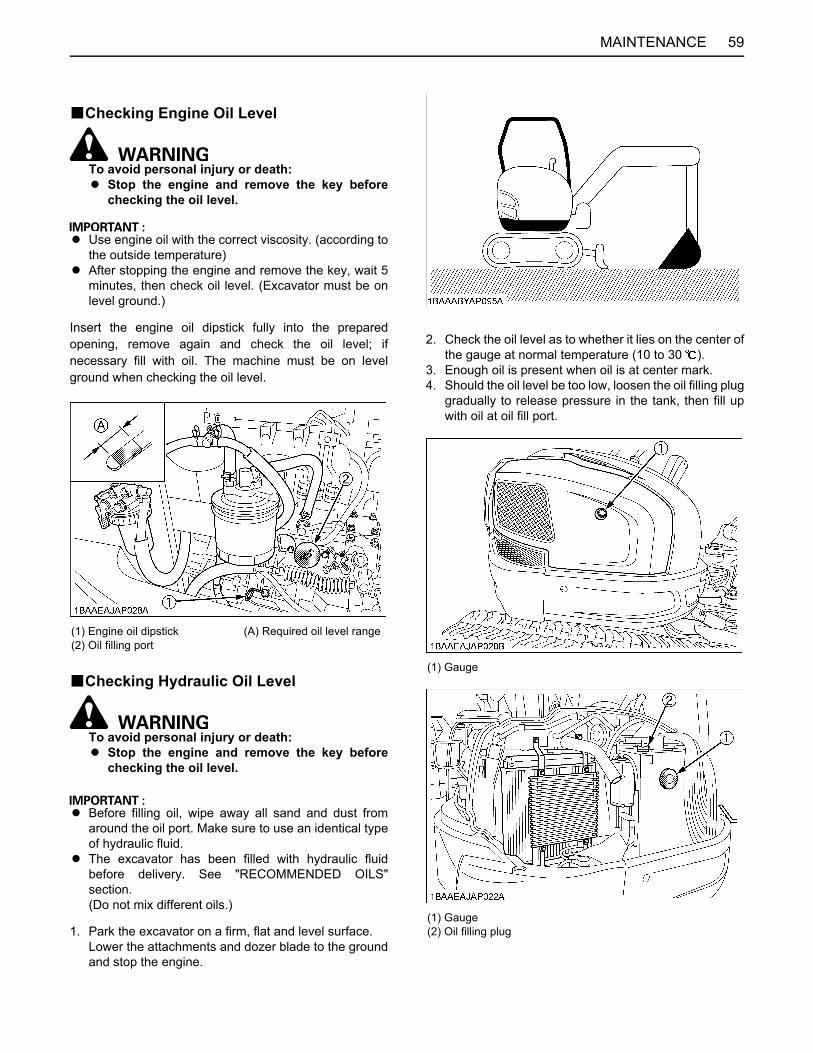
59MAINTENANCE
BChecking Engine Oil Level
To avoid personal injury or death:A Stop the engine and remove the key before
checking the oil level.
A Use engine oil with the correct viscosity. (according tothe outside temperature)
A After stopping the engine and remove the key, wait 5minutes, then check oil level. (Excavator must be onlevel ground.)
Insert the engine oil dipstick fully into the preparedopening, remove again and check the oil level; ifnecessary fill with oil. The machine must be on levelground when checking the oil level.
BChecking Hydraulic Oil Level
To avoid personal injury or death:A Stop the engine and remove the key before
checking the oil level.
A Before filling oil, wipe away all sand and dust fromaround the oil port. Make sure to use an identical typeof hydraulic fluid.
A The excavator has been filled with hydraulic fluidbefore delivery. See "RECOMMENDED OILS"section.(Do not mix different oils.)
1. Park the excavator on a firm, flat and level surface.Lower the attachments and dozer blade to the groundand stop the engine.
2. Check the oil level as to whether it lies on the center ofthe gauge at normal temperature (10 to 30 ).
3. Enough oil is present when oil is at center mark.4. Should the oil level be too low, loosen the oil filling plug
gradually to release pressure in the tank, then fill upwith oil at oil fill port.
(1) Engine oil dipstick(2) Oil filling port
(A) Required oil level range
(1) Gauge
(1) Gauge(2) Oil filling plug

MAINTENANCE60
BChecking V-belt
To avoid personal injury or death:A Stop the engine and remove the key before
checking the V-belt.A Check the V-belt for cracks and proper tension.
(See "Adjusting V-belt Tension" in "REGULARCHECKS AND MAINTENANCE WORK"section.)
BChecking Radiator and Oil Cooler
To avoid personal injury or death:A Always stop the engine and remove the key
before checking the radiator.A Wear eye protection when cleaning with
compressed air.A Replace all water hoses every two years.A Inspect all water hoses daily.
Have the excavator repaired immediately if anyof the following defects are discovered.(Such defects may cause burns or injury. Theymay also cause engine failure or seriousengine damage.)A Scratches, cracks or swelling in water
hoses.A Water leaks at joints or connecting points.A Missing or damaged water hose protective
sleeve or grommet.A Loose mounting bolt, damaged bracket.
A Do not touch the water hoses or the heater withyour hand. You may get burned.
A If the window fails to defrost in extremeconditions or becomes cloudy whendehumidifying the CAB, remove moisture withsoft cloth.
A Never block all of the air outlets, systemmalfunction may occur.
1. Check to see if the fins are clogged with dirt. If so,remove the dirt using compressed air or a hose. When cleaning, wear eye protection.
2. Check the rubber hoses for damage and replace ifcracked or old. Check if the hose clamps are tightenough.
A Radiator and oil cooler fins and ribs must be clean inorder to avoid overheating the engine and to allow freeflow of air through the cooling elements.
A Pressure of compressed air must be under 205 kPa(2.1 kgf.cm ).
(1) Radiator(2) Oil cooler
(1) Hose clamp(2) Rubber hose

61MAINTENANCE
BChecking Washer LiquidIf the windows washer is switched on with the washerliquid tank empty, the motor may be damaged. Alwayskeep the tank filled.
BChecking and Cleaning Engine and Electrical Wiring
To avoid personal injury or death:A Always stop the engine and remove the key
before cleaning the wiring, cables and engine.
Before starting, check whether flammable substanceshave gathered on the battery, the cables and wiring, themuffler or on the engine. Remove thoroughly.Check the electrical circuitry for disconnections, shorts orloose terminals.
BWashing Whole Machine
A Do not wash the excavator with the engine running.Water could enter the air filter and damage the engine.Make sure that the air filter is kept dry.
A Remove the mud before washing the machine.
BGreasing Front Attachments (without Bucket Pin and Boom Swing Fulcrum)
To avoid personal injury or death:A First lower all attachments on the ground then
stop the engine and remove the key. A While greasing, take care not to step on the
bucket teeth.
A When doing excavation work in water, generouslygrease the following points. After ending work, greaseagain.
Grease the marked grease fittings shown by arrows in theillustration below.
(1) Washer liquid tank
(1) Boom bottom linkage(2) Arm bottom linkage(3) Boom cylinder boss(4) Arm cylinder boss(5) Bucket cylinder boss
(1) Swing cylinder boss

MAINTENANCE62
BGreasing Bucket PinGrease the marked grease fittings shown by arrows in theillustration below.
BGreasing Boom Swing FulcrumGrease the marked grease fittings shown by arrows in theillustration below.
(1) Dozer cylinder boss(2) Dozer linkage pin

63REGULAR CHECKS AND MAINTENANCE WORK
REGULAR CHECKS AND MAINTENANCE WORK
To avoid personal injury or death:A When operating, keep hands and body inside
of the ROPS/OPG (Top Guard Level I)protective envelope.
A Do not touch the control levers and the pedalsfrom outside the cab during the enginerunning.
EVERY 50 SERVICE HOURSBDraining the Water from the Fuel Tank
To avoid personal injury or death:A Before draining the water from the fuel tank, be
sure to stop the engine and remove the key.A Do not smoke during inspection.
1. Open the drain plug.
BDraining Water Separator[Checking and Draining]Water and dirt contained in fuel will settle down in thewater separator. When such foreign substances aredeposited, set the water separator handle to the "OFF"position. Loosen the retainer ring and remove the cup.Then dump water in the cup.
[Cleaning]1. Set the water separator handle to the "OFF" position.2. Loosen and remove the cup proper, and clean its
inside with light oil.3. Tighten up the cup proper.
A As water is collected, the red float goes up.When the float has reached the specified line,immediately drain the water separator.
A In reattaching the water separator, be careful to keepoff dust and dirt.
A Be sure to purge the fuel system before getting themachine restarted.(See "PURGING OF THE FUEL SYSTEM" in"OTHER CHECKS AND REPLACEMENTS"section.)
(1) Drain plug (A) Open(B) Close
(1) Retainer ring(2) Cup(3) Water separator handle(4) Line(5) Float
(A) Loosen(B) Tighten
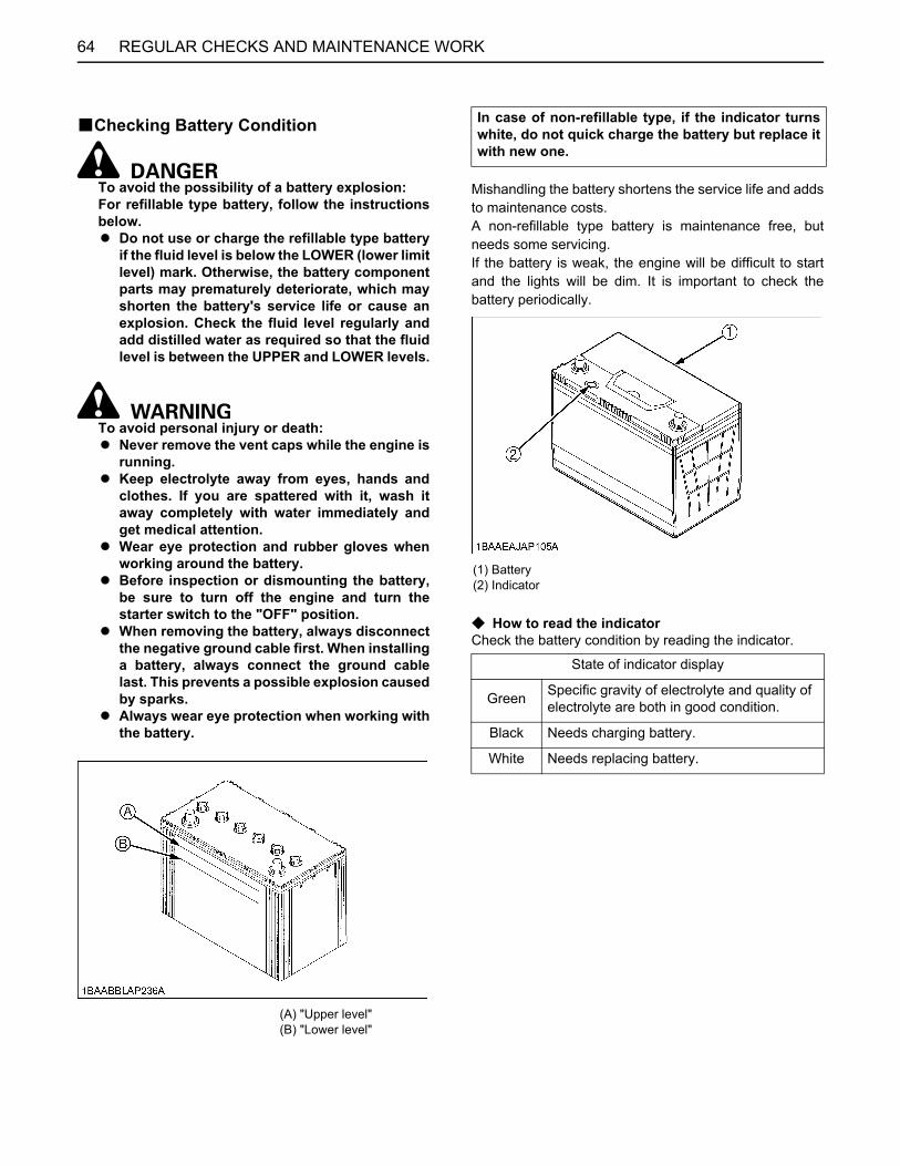
REGULAR CHECKS AND MAINTENANCE WORK64
BChecking Battery Condition
To avoid the possibility of a battery explosion:For refillable type battery, follow the instructionsbelow.A Do not use or charge the refillable type battery
if the fluid level is below the LOWER (lower limitlevel) mark. Otherwise, the battery componentparts may prematurely deteriorate, which mayshorten the battery's service life or cause anexplosion. Check the fluid level regularly andadd distilled water as required so that the fluidlevel is between the UPPER and LOWER levels.
To avoid personal injury or death:A Never remove the vent caps while the engine is
running.A Keep electrolyte away from eyes, hands and
clothes. If you are spattered with it, wash itaway completely with water immediately andget medical attention.
A Wear eye protection and rubber gloves whenworking around the battery.
A Before inspection or dismounting the battery,be sure to turn off the engine and turn thestarter switch to the "OFF" position.
A When removing the battery, always disconnectthe negative ground cable first. When installinga battery, always connect the ground cablelast. This prevents a possible explosion causedby sparks.
A Always wear eye protection when working withthe battery.
Mishandling the battery shortens the service life and addsto maintenance costs.A non-refillable type battery is maintenance free, butneeds some servicing.If the battery is weak, the engine will be difficult to startand the lights will be dim. It is important to check thebattery periodically.
C How to read the indicatorCheck the battery condition by reading the indicator.
(A) "Upper level"(B) "Lower level"
In case of non-refillable type, if the indicator turnswhite, do not quick charge the battery but replace itwith new one.
(1) Battery(2) Indicator
State of indicator display
Green Specific gravity of electrolyte and quality of electrolyte are both in good condition.
Black Needs charging battery.
White Needs replacing battery.

65REGULAR CHECKS AND MAINTENANCE WORK
C Battery Charging
To avoid personal injury or death: A When the battery is being activated, hydrogen
and oxygen gases in the battery are extremelyexplosive. Keep open sparks and flames awayfrom the battery at all times, especially whencharging the battery.
A When charging the battery, remove batteryvent plugs. (if equipped)
A When disconnecting the cable from the battery,start with the negative terminal first.When connecting the cable to the battery, startwith the positive terminal first.
A Never check battery charge by placing a metalobject across the posts.Use a voltmeter or hydrometer.
1. To slow charge the battery, connect the batterypositive terminal to the charger positive terminal andthe negative to the negative, then recharge in thestandard fashion.
2. A boost charge is applied only to refillable type and isonly for emergencies. It will partially charge the batteryat a high rate and in a short time.When using a boost-charged battery, it is necessary torecharge the battery as early as possible.Failure to do this will shorten the battery's service life.
3. The battery is charged if the indicator display turnsgreen from black.
4. When exchanging an old battery for a new one, abattery of equal specification.
C Direction for Storage1. When storing the machine for long periods of time,
remove the battery from machine, adjust theelectrolyte to the proper level and store in a dry placeout of direct sunlight.
2. The battery self-discharges while it is stored.Recharge it once every three months in hot seasonsand once every six months in cold seasons.
BGreasing Swing Bearing Teeth1. Pump grease with the grease gun through the grease
fitting.2. Grease at each 90 (1.58 rad.) position of the swing
frame.3. Fill with approx. 50g of grease (approx. 20 to 30
pumps with the grease gun at each position).Distribute the grease over the teeth.
(1) Battery
Battery Type Volts (V) Capacity
GP24 (80D26R) 12 55 (at 5H.R(A.H))
Battery TypeReserve Capacity
(min)
Cold Cranking
Amps
NormalChargingRate (A)
GP24 (80D26R) 133 582 6.5
(1) Grease fitting (for swing bearing teeth)
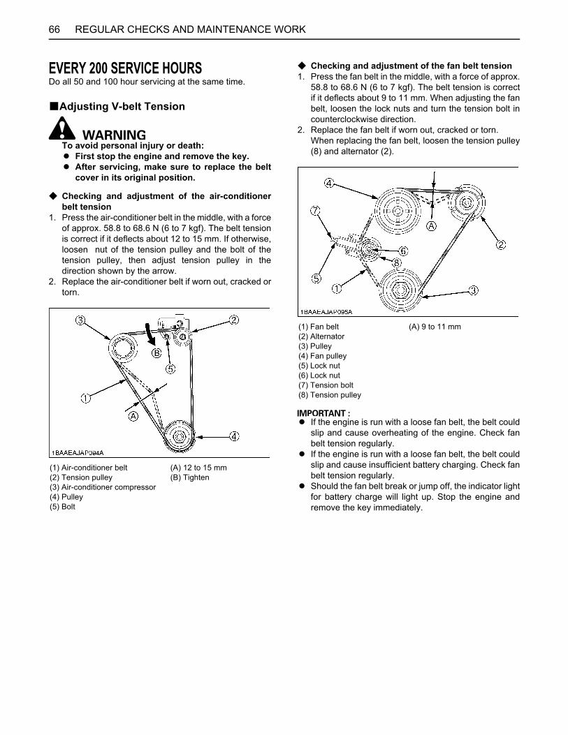
REGULAR CHECKS AND MAINTENANCE WORK66
EVERY 200 SERVICE HOURSDo all 50 and 100 hour servicing at the same time.
BAdjusting V-belt Tension
To avoid personal injury or death:A First stop the engine and remove the key.A After servicing, make sure to replace the belt
cover in its original position.
C Checking and adjustment of the air-conditionerbelt tension
1. Press the air-conditioner belt in the middle, with a forceof approx. 58.8 to 68.6 N (6 to 7 kgf). The belt tensionis correct if it deflects about 12 to 15 mm. If otherwise,loosen nut of the tension pulley and the bolt of thetension pulley, then adjust tension pulley in thedirection shown by the arrow.
2. Replace the air-conditioner belt if worn out, cracked ortorn.
C Checking and adjustment of the fan belt tension1. Press the fan belt in the middle, with a force of approx.
58.8 to 68.6 N (6 to 7 kgf). The belt tension is correctif it deflects about 9 to 11 mm. When adjusting the fanbelt, loosen the lock nuts and turn the tension bolt incounterclockwise direction.
2. Replace the fan belt if worn out, cracked or torn.When replacing the fan belt, loosen the tension pulley(8) and alternator (2).
A If the engine is run with a loose fan belt, the belt couldslip and cause overheating of the engine. Check fanbelt tension regularly.
A If the engine is run with a loose fan belt, the belt couldslip and cause insufficient battery charging. Check fanbelt tension regularly.
A Should the fan belt break or jump off, the indicator lightfor battery charge will light up. Stop the engine andremove the key immediately.
(1) Air-conditioner belt(2) Tension pulley(3) Air-conditioner compressor(4) Pulley(5) Bolt
(A) 12 to 15 mm(B) Tighten
(1) Fan belt(2) Alternator(3) Pulley(4) Fan pulley(5) Lock nut(6) Lock nut(7) Tension bolt(8) Tension pulley
(A) 9 to 11 mm

67REGULAR CHECKS AND MAINTENANCE WORK
BChecking Radiator Hoses and Clamps
To avoid personal injury or death:A Wait long enough for the radiator coolant to
cool down.
Check the coolant hoses for proper connection. Thischeck should be carried out every 200 hours or every 6months, whichever comes first.1. Should the hose clamps become loose or coolant
leaks, tighten the hose clamps properly.2. Should the radiator hoses become swollen, aged or
cracked, they must be replaced and the hose clampstightened again properly.
BGrease Swing Ball Bearing1. Grease through the respective grease fitting. (at the
central fitting) 2. Grease at each 90 (1.58 rad.) position of the swing
frame.Using the grease gun, apply 5 shots at every position.
BInspection and Cleaning Air Filter ElementOpen the engine hood and remove the dust-cover. Takeout only outer element, clean the element, case interiorand reassemble. During reassembly, take care to installthe dust-cover so that its TOP mark (arrow) faces up-wards. Do not remove the inner element.
A Should the machine be used in extremely dusty areas,the air filter element must be inspected and cleanedmore frequently than in the specified maintenanceperiods.
A The air filter has a dry element, keep free from oil. A Do not run the engine without the air filter.
(1) Hose clamp (2) Radiator hose
(1) Grease fitting
(1) Inner element (2) Outer element (3) Dust-cover(4) Clamps

REGULAR CHECKS AND MAINTENANCE WORK68
BAir Filter Maintenance
To avoid personal injury or death:A Wear eye protection.
The quickest and safest method of maintenance is theexchange of the paper cartridge. Furthermore there aredifferent methods of cleaning the cartridge.
C Cleaning with compressed airPressure of compressed air must be under 205 kPa (2.1kgf/ ), and the cartridge should be blown clean from theinside to the outside until the dust deposits are noticeablyreduced.
A If the air suction is still inadequate, or the color of theexhaust gases is abnormal even after the cleaning, theair filter cartridge must be replaced.
BChecking Fuel Line and Intake Air Line1. Check to see that all lines and hose clamps are
tightened and not damaged.2. If hoses and clamps are found worn or damaged,
replace or repair them at once.
(1) Fuel lines(2) Clamp bands
(1) Hoses(2) Hose clamps
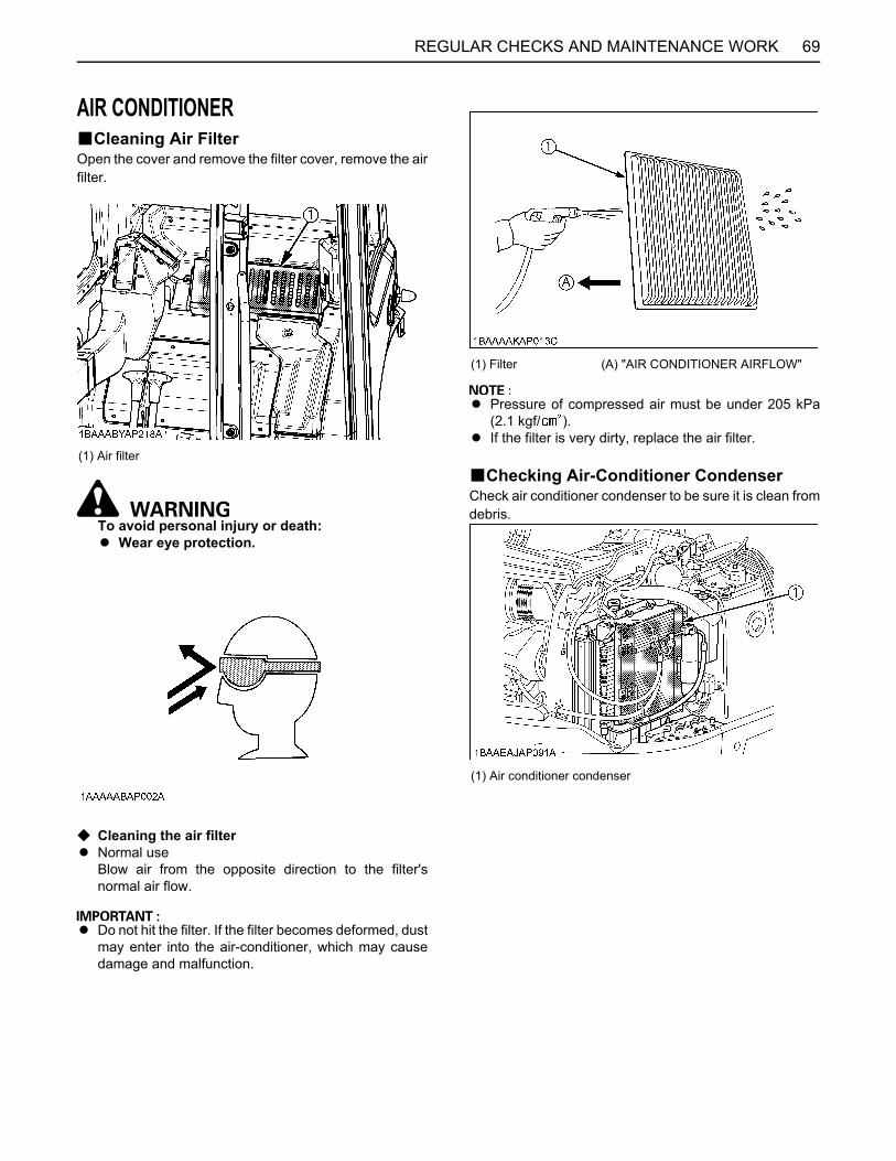
69REGULAR CHECKS AND MAINTENANCE WORK
AIR CONDITIONERBCleaning Air FilterOpen the cover and remove the filter cover, remove the airfilter.
To avoid personal injury or death:A Wear eye protection.
C Cleaning the air filterA Normal use
Blow air from the opposite direction to the filter'snormal air flow.
A Do not hit the filter. If the filter becomes deformed, dustmay enter into the air-conditioner, which may causedamage and malfunction.
A Pressure of compressed air must be under 205 kPa(2.1 kgf/ ).
A If the filter is very dirty, replace the air filter.
BChecking Air-Conditioner CondenserCheck air conditioner condenser to be sure it is clean fromdebris.
(1) Air filter
(1) Filter (A) "AIR CONDITIONER AIRFLOW"
(1) Air conditioner condenser
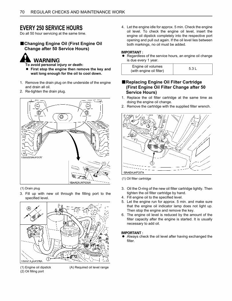
REGULAR CHECKS AND MAINTENANCE WORK70
EVERY 250 SERVICE HOURSDo all 50 hour servicing at the same time.
BChanging Engine Oil (First Engine Oil Change after 50 Service Hours)
To avoid personal injury or death:A First stop the engine then remove the key and
wait long enough for the oil to cool down.
1. Remove the drain plug on the underside of the engineand drain all oil.
2. Re-tighten the drain plug.
3. Fill up with new oil through the filling port to thespecified level.
4. Let the engine idle for approx. 5 min. Check the engineoil level. To check the engine oil level, insert theengine oil dipstick completely into the respective portopening and pull out again. If the oil level lies betweenboth markings, no oil must be added.
A Regardless of the service hours, an engine oil changeis due every 1 year.
BReplacing Engine Oil Filter Cartridge (First Engine Oil Filter Change after 50 Service Hours)
1. Replace the oil filter cartridge at the same time asdoing the engine oil change.
2. Remove the cartridge with the supplied filter wrench.
3. Oil the O-ring of the new oil filter cartridge lightly. Thentighten the oil filter cartridge by hand.
4. Fill engine oil to the specified level.5. Let the engine run for approx. 5 min. and make sure
that the engine oil indicator lamp does not light up.Then stop the engine and remove the key.
6. The engine oil level is reduced by the amount of thefilter capacity after the engine is started. It is usuallynecessary to add oil.
A Always check the oil level after having exchanged thefilter.
(1) Drain plug
(1) Engine oil dipstick(2) Oil filling port
(A) Required oil level range
Engine oil volumes(with engine oil filter) 5.3 L
(1) Oil filter cartridge
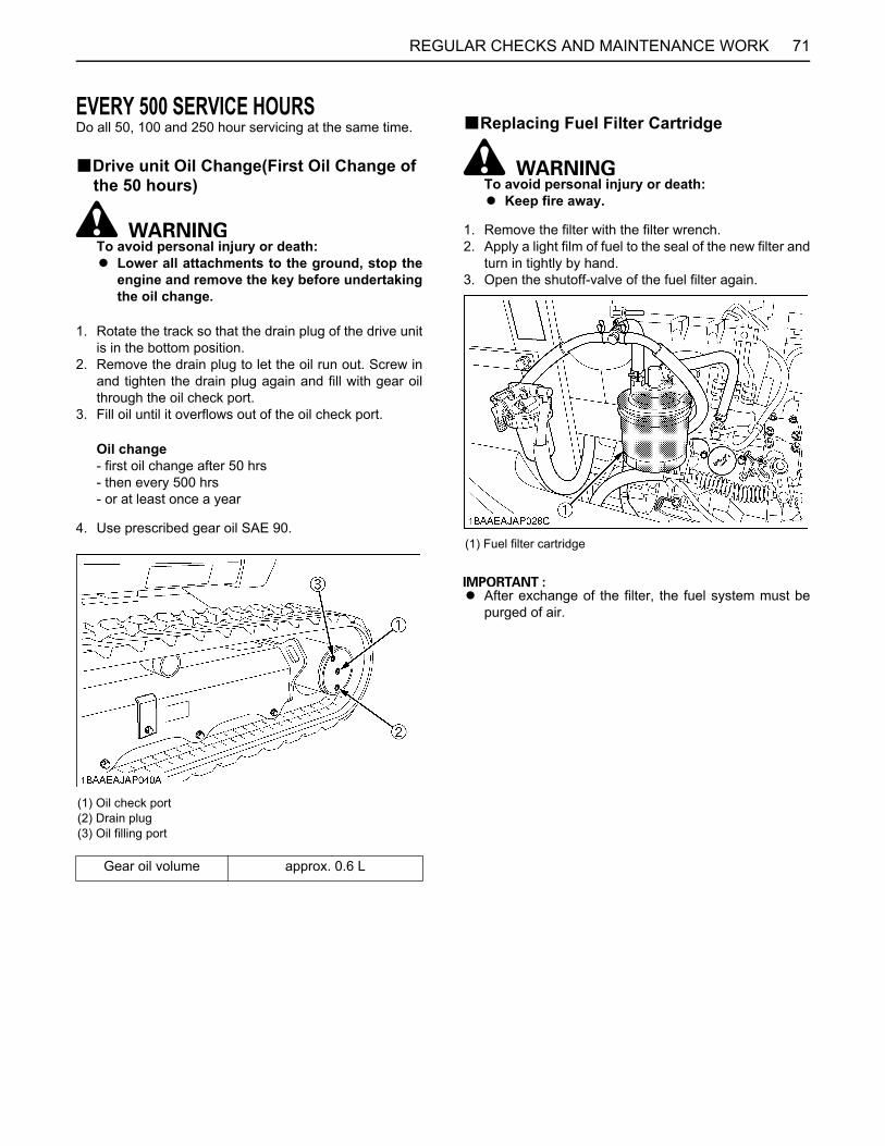
71REGULAR CHECKS AND MAINTENANCE WORK
EVERY 500 SERVICE HOURSDo all 50, 100 and 250 hour servicing at the same time.
BDrive unit Oil Change(First Oil Change of the 50 hours)
To avoid personal injury or death:A Lower all attachments to the ground, stop the
engine and remove the key before undertakingthe oil change.
1. Rotate the track so that the drain plug of the drive unitis in the bottom position.
2. Remove the drain plug to let the oil run out. Screw inand tighten the drain plug again and fill with gear oilthrough the oil check port.
3. Fill oil until it overflows out of the oil check port.
Oil change- first oil change after 50 hrs- then every 500 hrs - or at least once a year
4. Use prescribed gear oil SAE 90.
BReplacing Fuel Filter Cartridge
To avoid personal injury or death:A Keep fire away.
1. Remove the filter with the filter wrench.2. Apply a light film of fuel to the seal of the new filter and
turn in tightly by hand.3. Open the shutoff-valve of the fuel filter again.
A After exchange of the filter, the fuel system must bepurged of air.
(1) Oil check port(2) Drain plug(3) Oil filling port
Gear oil volume approx. 0.6 L
(1) Fuel filter cartridge

REGULAR CHECKS AND MAINTENANCE WORK72
BReplacing Hydraulic Return Filter Element (First replacement after 250 service hours)
To avoid personal injury or death:A Remove the oil filter element only after the oil in
the hydraulic tank has cooled down.
1. Remove the cover of the hydraulic tank.2. Pull out the filter support by the top plate from the
hydraulic tank.3. Remove the return filter from the filter support with a
fork wrench and exchange the filter.
A Always check the oil level when replacing the filter.
BReplacing Breather FilterSee "Replacing Hydraulic Return Filter Element" in"EVERY 500 SERVICE HOURS" section.
BReplacing Fan BeltConsult your local KUBOTA dealer for this service.
EVERY 1000 SERVICE HOURSDo all 50, 100, 200, 250 and 500 hour servicing at thesame time.
BReplacing the Hydraulic Pilot Filter Element
To avoid personal injury or death:A Before replacing the element, wait long enough
for the hydraulic fluid to cool down.1. Remove the bonnet left cover.2. Gradually loosen the oil filling plug on the tank to
release the pressure in the hydraulic system.3. Remove the pilot filter case from the head cover.4. Wrench and pull out the element downward.5. Replace the O-ring with a new one.6. Apply a light coating of clean hydraulic oil to the O-ring
and fit it to the case firmly. Be careful not to scratch theO-ring.
7. Fit the case to the head cover.8. Let the engine run for approx. 3 minutes.9. Check the oil level of hydraulic oil tank, then tighten the
oil filling plug.(1) Set bolt(2) Filter support
(3) Return filter(4) Cover
(1) Bonnet left cover
(1) Head cover (2) Element (3) O-ring (4) Case

73REGULAR CHECKS AND MAINTENANCE WORK
BHydraulic Oil Change (Including Replacing of the Suction Filter in the Hydraulic Tank)
To avoid personal injury or death: A Wait long enough for the hydraulic fluid to cool
down. Then begin with the change of thehydraulic fluid.
1. Park the excavator on a firm, flat and level surface.Lower the attachments and dozer blade to the groundand stop the engine.
2. Remove the drain plug on the underside of thehydraulic tank and drain the oil.
3. Remove the cover of the hydraulic tank.4. With a fork wrench or similar, remove and replace the
filter with new one.5. Retighten the drain plug, and remove iron powder
adhering to the magnet.
6. Fill oil through the oil filling opening on the top side ofthe tank.
7. let the engine run for approx. 5 min. and check the oillever again.
A Should dirt deposits be in the hydraulic tank , removewith the help of a clean cloth and light oil.
(1) Drain plug
(1) Set bolt(2) Filter support(3) Return filter(4) Cover
(5) Suction filter(6) Drain plug(7) Bolt(8) Breather filter
Hydraulic oil volumesHydraulic tank 35 L
Whole oil volumes 61 L
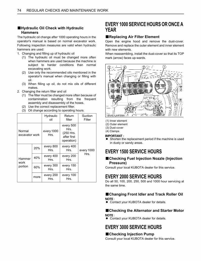
REGULAR CHECKS AND MAINTENANCE WORK74
BHydraulic Oil Check with Hydraulic Hammers
The hydraulic oil change after 1000 operating hours in theoperator's manual is based on normal excavator work.Following inspection measures are valid when hydraulichammers are used: 1. Changing and filling up of hydraulic oil
(1) The hydraulic oil must be changed more oftenwhen hammers are used because the machine issubject to harder conditions than normalexcavating work.
(2) Use only the recommended oils mentioned in theoperator's manual when changing or filling withoil.
(3) When filling up oil, do not mix oils of differentmakes.
2. Changing the return filter and oil(1) The filter must be changed more often because of
contamination resulting from the frequentassembly and disassembly of the hoses.
(2) Use the correct replacement filter. (3) Oil change according to operating hours.
EVERY 1000 SERVICE HOURS OR ONCE A YEARBReplacing Air Filter ElementOpen the engine hood and remove the dust-cover.Remove and replace the outer element and inner elementwith new elements.When reassembling, install the dust-cover so that its TOPmark (arrow) faces up-wards.
A Shorten the replacement period if the machine is usedin dusty or sandy areas.
EVERY 1500 SERVICE HOURSBChecking Fuel Injection Nozzle (Injection
Pressure)Consult your local KUBOTA dealer for this service.
EVERY 2000 SERVICE HOURSDo all 50, 100, 200, 250, 500 and 1000 hour servicing atthe same time.
BChanging Front Idler and Track Roller Oil
A Contact your KUBOTA dealer for details.
BChecking the Alternator and Starter Motor
A Contact your KUBOTA dealer for details.
EVERY 3000 SERVICE HOURSBChecking Injection PumpConsult your local KUBOTA dealer for this service.
Hydraulic oil
Return filter
Suction Filter
Normal excavator work
every 1000 Hrs.
every 500 Hrs.
(250 Hrs. after first
operation)
every 1000 Hrs.
Hammerworkportion
20% every 800 Hrs.
every 400 Hrs.
40% every 400 Hrs.
every 200 Hrs.
60% every 300 Hrs.
every 150 Hrs.
more every 200 Hrs.
every 100 Hrs.
(1) Inner element(2) Outer element(3) Dust-cover(4) Clamps

75REGULAR CHECKS AND MAINTENANCE WORK
ANNUAL SERVICINGBElectrical Wiring and FusesCheck the terminals periodically for proper connections.Loose wiring or damaged cables can cause improperfunctioning or short circuiting of the electrical system.Check wiring and replace damaged componentsimmediately. If a fuse blows out soon after having beenreplaced, contact your nearest KUBOTA dealer. Neveruse a fuse other than specified.
BChecking the Electrical CircuitCheck the electrical circuitry for disconnections, shorts orloose terminals.
BChecking Air-Conditioner Pipes and Hoses
To avoid personal injury or death:A Do not touch the coolant hoses or the heater
with your hand. You may get burned.
1. Check to see that all lines and hose clamps are tightand not damaged.
2. If hoses and clamps are found worn or damaged,replace or repair them at once. (Consult your localKUBOTA dealer for this service.)
BIENNIAL SERVICING
To avoid personal injury or death:A Do not loosen the radiator cap before the
radiator has cooled down sufficiently. Onlyloosen the cap after allowing enough time forthe pressure in the system to be reduced.Thereafter, one can remove the cap completely.
BReplacing Air-Conditioner Pipes and Hoses
To avoid personal injury or death:A Do not touch the coolant hoses or the heater
with your hand. You may get burned.
Replace air-conditioner pipes and hoses every two years.If the hoses or pipes are swollen, hard or cracked, theymust be replaced earlier. (Consult your local KUBOTADealer for this service.)
BReplacement of Radiator Hoses and Hose Clamps
Replace radiator hoses and hose clamps every two years.If the hoses are swollen, hard or cracked, they must bereplaced earlier.
BChanging Radiator Coolant
To avoid personal injury or death:A When using anti-freeze, use protective clothing
such as rubber gloves (Anti-freeze ispoisonous.).
A If you accidentally swallowed anti-freeze, seekmedical attention at once.
A When anti-freeze comes in contact with theskin or clothing, wash it off immediately.
A Do not mix different types of Anti-freeze. Themixture can produce a chemical reactioncausing harmful substances.
A Anti-freeze is extremely flammable andexplosive under certain conditions. Keep fireand children away from anti-freeze.
A When draining fluids from the engine, use acontainer underneath the engine body to catchthe fluids.
A Do not pour waste onto the grounds, down adrain, or into any water source.
A Also, observe the relevant environmentalprotection regulations when disposing of anti-freeze.
A If swallowed, anti-freeze is poisonous topeople, animals and birds.
(1) Hose clamp(2) Radiator hose

REGULAR CHECKS AND MAINTENANCE WORK76
Stop the engine, then remove the key and wait until it hascooled down completely.1. Open the drain plug on the bottom of the radiator and
drain coolant completely. Should a recovery tank beequipped, disconnect the line from the tank floor andthen open the drain shutoff-valve.
2. To clean, rinse the radiator with water.3. Close the drain plug, and fill the radiator and the
recovery tank with coolant fluid. Let the engine idle forabout 5 min. Stop the engine and remove the key.
4. Check the coolant level of recovery tank and add thecoolant if necessary.
5. The shipped machine has been filled with 50% anti-freeze solution.
A Do not operate the engine without coolant. A To fill the radiator system and the recovery tank, use
fresh water and anti-freeze fluid. A When the anti-freeze is mixed with water, the anti-
freeze mixing ratio must be less than 50%.A Tighten the radiator cap properly. If the cap is loosely
or not properly fitted, overheating of the engine canresult due to coolant fluid loss.
BReplacing Fuel Hoses and Hose ClampsReplace the hoses and clamps.(See "Checking Fuel Line and Intake Air Line" in "EVERY200 SERVICE HOURS")
(1) Drain plug
(1) Radiator cap
(1) Recovery tank (A) "FULL"(B) "LOW"
Cooling waterCanopy Approx. 4.3 L
Cabin Approx. 4.7 L
Radiatorrecovery tank Approx. 0.85 L
(1) Fuel lines(2) Clamp bands
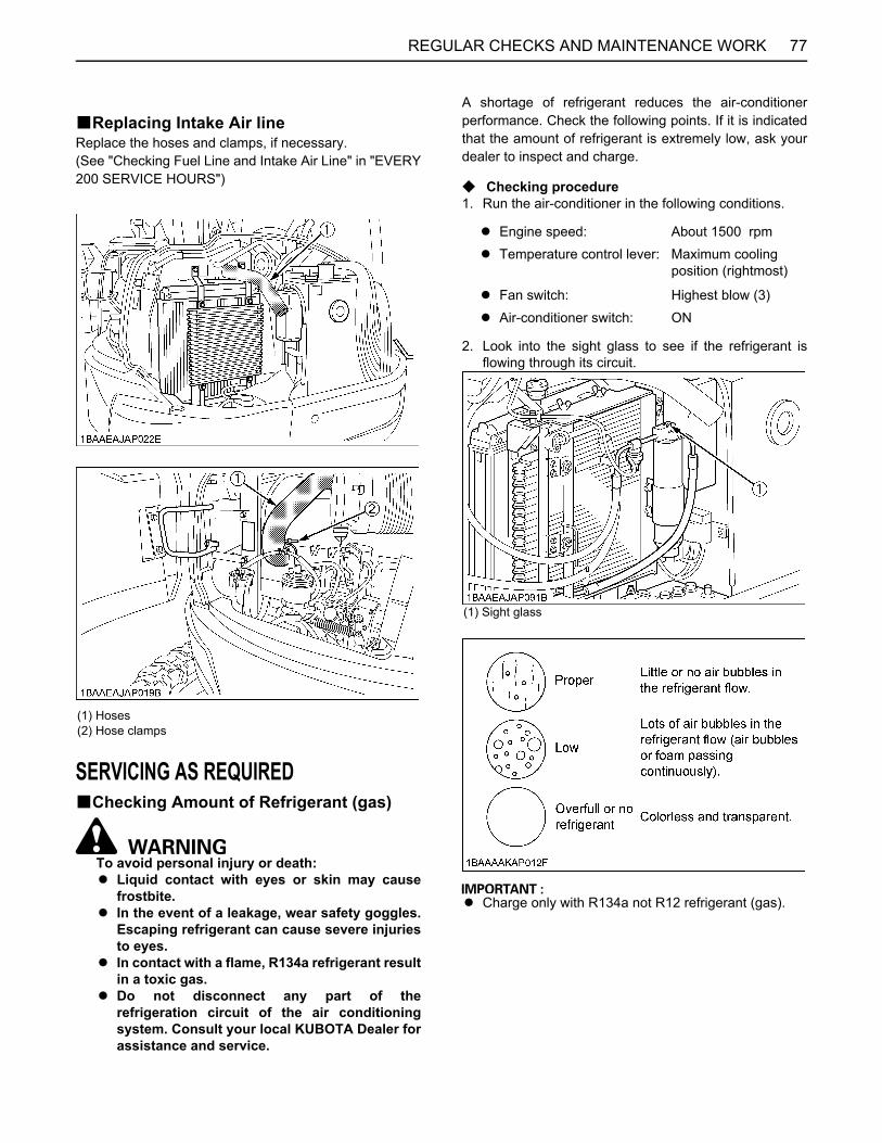
77REGULAR CHECKS AND MAINTENANCE WORK
BReplacing Intake Air lineReplace the hoses and clamps, if necessary.(See "Checking Fuel Line and Intake Air Line" in "EVERY200 SERVICE HOURS")
SERVICING AS REQUIREDBChecking Amount of Refrigerant (gas)
To avoid personal injury or death:A Liquid contact with eyes or skin may cause
frostbite.A In the event of a leakage, wear safety goggles.
Escaping refrigerant can cause severe injuriesto eyes.
A In contact with a flame, R134a refrigerant resultin a toxic gas.
A Do not disconnect any part of therefrigeration circuit of the air conditioningsystem. Consult your local KUBOTA Dealer forassistance and service.
A shortage of refrigerant reduces the air-conditionerperformance. Check the following points. If it is indicatedthat the amount of refrigerant is extremely low, ask yourdealer to inspect and charge.
C Checking procedure1. Run the air-conditioner in the following conditions.
2. Look into the sight glass to see if the refrigerant isflowing through its circuit.
A Charge only with R134a not R12 refrigerant (gas).
(1) Hoses(2) Hose clamps
A Engine speed: About 1500 rpmA Temperature control lever: Maximum cooling
position (rightmost)
A Fan switch: Highest blow (3)A Air-conditioner switch: ON
(1) Sight glass

78 OTHER ADJUSTMENTS AND REPLACEMENTS
OTHER ADJUSTMENTS AND REPLACEMENTS
PURGING OF THE FUEL SYSTEM1. Fill up the fuel tank with fuel. 2. Turn the starter key to the position "RUN".3. The air in the fuel system will automatically be purgedwithin one minute.
A If the purging was insufficient, the engine stops rightafter starting. In this case repeat steps 2 to 3 again.
ADJUSTMENT OF TRACKSC To loosen the tracks, follow the following
procedure:
To avoid personal injury or death: A Do not loosen the grease fitting completely or
too quickly. Otherwise grease under highpressure in the tension cylinder could squirtout.
A Do not crawl under the excavator.
1. Loosen the bolts and remove the cover.2. Using a socket wrench, loosen the grease fitting a few
turns.3. When grease oozes out from the thread, rotate the
track and loosen the track in the lifted position (seeillustration).
After adjustment is completed:Using the socket wrench, tighten the grease fitting.Tightening torque must be between 98 to 108 N-m.
A If the tracks are too tight, wear is increased. A If the tracks are too loose, the track pads may collide
with the sprocket and wear is increased.The track may dislocate or come off.
A Clean the track after every use. A Should the track tension be high due to sticking mud,
lift the track with the help of the boom, arm and bucket,idle the engine and remove mud from the track byrotating it.
C Tense the tracks as specified:1. Loosen the bolt and remove the cover. 2. Apply grease to the grease fitting.
3. Rubber TracksTense the track in the lifted position, so that thedistance "A" (clearance between the track roller andthe inside surface of the track) see illustration, in thiscase, if there is a seam mark " " on the insidesurface of the track, the seam mark " " is positionedon the top center between the idler and the sprocket.
(1) Starter switch (A) "STOP"(B) "RUN"(C) "START"
(1) Cover(2) Bolt(3) Grease fitting(4) Grease gun
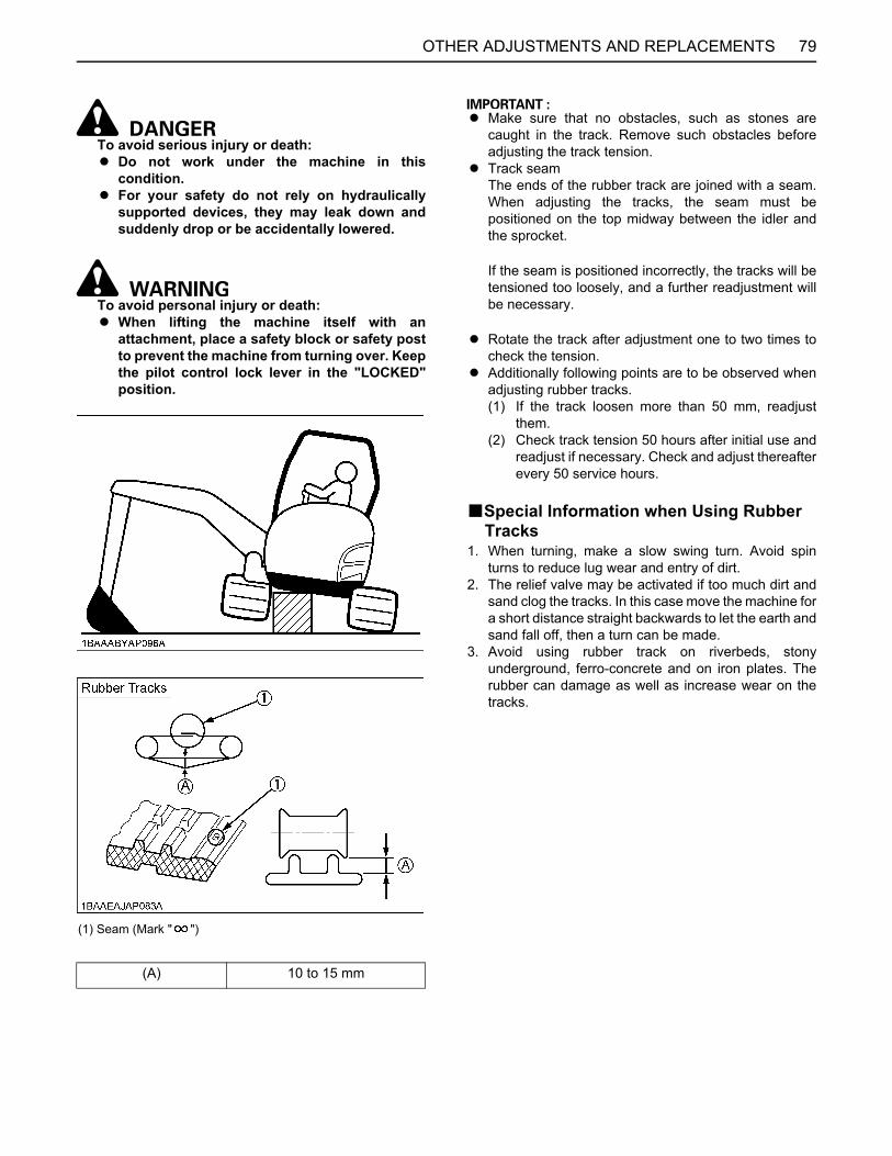
79OTHER ADJUSTMENTS AND REPLACEMENTS
To avoid serious injury or death:A Do not work under the machine in this
condition.A For your safety do not rely on hydraulically
supported devices, they may leak down andsuddenly drop or be accidentally lowered.
To avoid personal injury or death:A When lifting the machine itself with an
attachment, place a safety block or safety postto prevent the machine from turning over. Keepthe pilot control lock lever in the "LOCKED"position.
A Make sure that no obstacles, such as stones arecaught in the track. Remove such obstacles beforeadjusting the track tension.
A Track seamThe ends of the rubber track are joined with a seam.When adjusting the tracks, the seam must bepositioned on the top midway between the idler andthe sprocket.
If the seam is positioned incorrectly, the tracks will betensioned too loosely, and a further readjustment willbe necessary.
A Rotate the track after adjustment one to two times tocheck the tension.
A Additionally following points are to be observed whenadjusting rubber tracks. (1) If the track loosen more than 50 mm, readjust
them. (2) Check track tension 50 hours after initial use and
readjust if necessary. Check and adjust thereafterevery 50 service hours.
BSpecial Information when Using Rubber Tracks
1. When turning, make a slow swing turn. Avoid spinturns to reduce lug wear and entry of dirt.
2. The relief valve may be activated if too much dirt andsand clog the tracks. In this case move the machine fora short distance straight backwards to let the earth andsand fall off, then a turn can be made.
3. Avoid using rubber track on riverbeds, stonyunderground, ferro-concrete and on iron plates. Therubber can damage as well as increase wear on thetracks.
(1) Seam (Mark " ")
(A) 10 to 15 mm
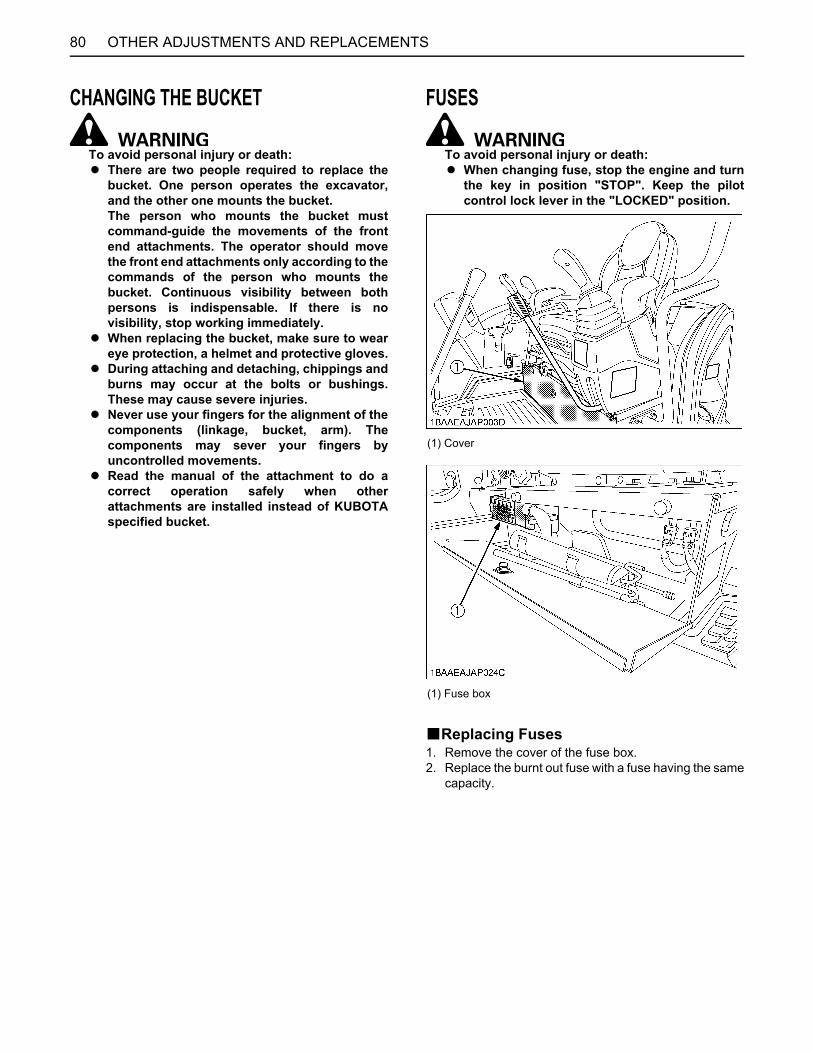
OTHER ADJUSTMENTS AND REPLACEMENTS80
CHANGING THE BUCKET
To avoid personal injury or death:A There are two people required to replace the
bucket. One person operates the excavator,and the other one mounts the bucket.The person who mounts the bucket mustcommand-guide the movements of the frontend attachments. The operator should movethe front end attachments only according to thecommands of the person who mounts thebucket. Continuous visibility between bothpersons is indispensable. If there is novisibility, stop working immediately.
A When replacing the bucket, make sure to weareye protection, a helmet and protective gloves.
A During attaching and detaching, chippings andburns may occur at the bolts or bushings.These may cause severe injuries.
A Never use your fingers for the alignment of thecomponents (linkage, bucket, arm). Thecomponents may sever your fingers byuncontrolled movements.
A Read the manual of the attachment to do acorrect operation safely when otherattachments are installed instead of KUBOTAspecified bucket.
FUSES
To avoid personal injury or death:A When changing fuse, stop the engine and turn
the key in position "STOP". Keep the pilotcontrol lock lever in the "LOCKED" position.
BReplacing Fuses1. Remove the cover of the fuse box. 2. Replace the burnt out fuse with a fuse having the same
capacity.
(1) Cover
(1) Fuse box

81OTHER ADJUSTMENTS AND REPLACEMENTS
BFuse Capacities and Circuits
[Canopy]
[CAB (Air-conditioner type)]
1 ECU (AC) 9 ECU (+B)2 Relay 10 Horn Switch3 Alternator 11 Horn4 Lever Lock 12 Work Light 5 Fuel Pump 13 Beacon6 Electrical Outlet 14 Room Light7 Engine Stop 15 ECU (POWER)8 Meter (+B) 16 Starter Signal
1 A/C Controller (+B) 12 Engine Stop2 Blower Motor 13 Meter (+B)3 ECU (AC) 14 ECU (+B)4 Relay 15 Horn Switch5 Alternator 16 Horn6 Lever Lock 17 Work Light7 Fuel Pump 18 Beacon8 Wiper / Washer 19 Room Light9 Radio (AC) 20 ECU (POWER)
10 Electrical Outlet 21 Starter Signal11 Compressor

OTHER ADJUSTMENTS AND REPLACEMENTS82
BAuxiliary ElectricMax power is less than 110 W including the equipped light55W.If you need another auxiliary electric, contact yourKUBOTA dealer for details.
BSlow Blow FuseSlow blow fuse is provided to protect the electrical circuits.If the slow blow fuse is blown, check the electrical circuitsfor trouble and then replace with a new compatible slowblow fuse.
[CAB]
[CANOPY]
C Replacement procedure[80 Amp. Slow-blow fuse]
1. Disconnect the negative cord of the battery.2. Remove the slow blow fuse case.
3. Open the slow blow fuse case cap and covers, thenremove the bolts and draw out the slow blow fuse (B).
(1) Auxiliary Electric
(1) Slow blow fuse
(A)
(B) 80A Alternator
(C) 50A Main Power (1)
(D) 50A Main Power (2)
(A)
(B) 80A Alternator
(C) 50A Main Power
(D)
(1) Slow blow fuse case
(1) Slow blow fuse case cap(2) Cover(3) Bolt(4) Slow blow fuse (B)

83TROUBLESHOOTING
TROUBLESHOOTING
If the excavator does not show the desired performance, or when trouble arises, refer to the table below and undertakeappropriate measures.Trouble Cause Countermeasure
Engine
Starting difficulties
Pilot control lock lever in "UNLOCK" position * Bring pilot control lock lever into "LOCKED" position.
Fuel is too viscous.* Check fuel tank and filter.* Remove impurities and water.* If necessary, replace filter.
Air or water in the fuel system
* Remove water from the fuel tank.* Check fuel pipe joint bolts and nuts for looseness.* Purging of the fuel system (for fuel filter and injection pump, see "PURGING OF THE FUEL SYSTEM" in the chapter "OTHER ADJUSTMENTS AND REPLACEMENTS".)
Oil viscosity is too high the engine runs sluggishly in winter.
* Pour hot water over the radiator.
Battery is almost dead; insufficient compression. * Recharge battery.
Insufficient engine power
Low fuel level * Check fuel and add if necessary.
Clogged air cleaner * Clean the air filter element.
Engine suddenly stops. Low fuel level * Check fuel and add if necessary.
* Purge the fuel system.
Abnormal exhaust gas color
Poor fuel * Use high quality fuel.
Too much engine oil * Drain engine oil to prescribed oil level.
Water temperaturein red zone (Overheating)
Defective seal of the water pump * Replace.
Worn or torn V-belt * Adjust or replace.
Thermostat is defect. * Replace.
Coolant level too low * Fill to prescribed level.
Radiator grill or fins are clogged. * Clean.
Coolant is contaminated with rust from the cylinder head or crank case.
* Replace coolant fluid and add anti-rust.
Defective radiator cap (Evaporation) * Replace.
Corroded coolant pipes * Clean.
Continuous operation under full load * Reduce load.

84 TROUBLESHOOTING
Engine
Water temperaturein red zone (Overheating)
Cylinder head gasket is damaged (Coolant loss). * Replace.
Engine oil level too low * Fill to prescribed level.
Maladjustment of fuel injection * Readjust ignition timing.
Use of poor fuel * Use prescribed fuel.
Hydraulic System
Boom, arm, bucket, drive, swing and dozer power is too low.
Hydraulic oil level too low * Add oil.
Leakages of hoses and / or joints * Replace hose or joint.
Swing motor and front attachment does not work.
Pilot control lock lever in "LOCKED" position * Bring pilot control lock lever into "UNLOCK" position.
Drive System
Deviation of drive direction
Blocked through stones * Remove.
Track too loose or too tight * Adjust accordingly.
AI System indicator light flashes. Fuse in fuse box defective * Replace the fuse.
Trouble Cause Countermeasure

85OPERATION UNDER COLD WEATHER CONDITIONS
OPERATION UNDER COLD WEATHER CONDITIONS
PREPARATION FOR OPERATION IN COLD WEATHER1. Replace engine oil and hydraulic oil with those ofviscosities suitable for cold weather.2. In cold weather, battery power drops, and the battery
fluid may freeze if the battery is not sufficientlycharged. To prevent the battery fluid from freezing, besure to keep the battery charged at least 75% or moreof its capacity after operation. To ease next starting, itis recommended to keep the battery stored in closedor heated rooms. If the battery fluid level is too low, donot add after operation, but add with the enginerunning before the next operation.
3. Add anti-freeze to coolant in the radiator and recoverytank, if the ambient temperature is expected to dropbelow 0 . Mixing ratio of water and anti-freezedepends on the expected ambient temperature.When mixing, stir it up well, and then fill into theradiator.
A Mixing ratio between water and anti-freeze
A Use permanent anti-freeze or long-life coolant.A Drain the coolant completely and clean the inside of
the radiator, then fill with the water and anti-freezemixture.
A The anti-freeze acts as an anti-corrosive, it is notnecessary to add an additive to the water and anti-freeze mixture.
A See "Coolant check" under "DAILY CHECKS" in"MAINTENANCE" for radiator fill volumes.
PROCEDURE AFTER COMPLETING WORKClean the excavator thoroughly after work and wipe dry.Otherwise mud and earth on the tracks could freeze if thetemperature drops below the 0 mark. Operation of theexcavator is then not possible. Store the excavator in adry place; if not possible, store on wooden planks or onmats. If the excavator is kept on damp or muddy ground,the tracks could freeze overnight. Operation of theexcavator is then not possible. Furthermore the drive unitmay be damaged.Additionally, the piston rods of the hydraulic cylindersmust be rubbed dry. Otherwise severe damage couldoccur if dirty water seeps through the seals.
AmbientTemperature -5 -10 -15 -20 -25 -30 -35
Antifreeze % 30 30 30 35 40 45 50
Water % 70 70 70 65 60 55 50

86 LONG STORAGE
LONG STORAGE
To avoid personal injury or death:A Do not clean the excavator with the engine running.A To avoid the danger of exhaust fume poisoning, do not operate the engine in a closed building without
proper ventilation.A When storing, remove the key from the starter switch to avoid unauthorized persons from operating the
excavator and getting injured.A Bring the excavator on a firm, flat, and level surface. Lower the attachments and dozer blade on the ground.
B Should the Excavator be Stored for a Longer Period of Time, Observe Following Procedures:1. The whole excavator should be cleaned thoroughly and in all cases stored indoors. If the excavator has to be kept
outdoors, lay out wooden planks on even ground, place the excavator on the planks and cover completely.2. Do an oil change and grease the excavator.3. Heavily grease the visible section of the cylinder rods.4. Remove the battery and store indoors.5. If it is expected that the temperature will sink below the 0 mark, add anti-freeze or drain coolant completely.
A Wash the excavator after stopping the engine.If you wash the excavator while running the engine, splashing water gets into the air cleaner through its intake andcause engine damage.Carefully, wash and do not splash water over the air cleaner while the engine is running.
B Observe Following Procedures when the Machine is to be Operated after Long Storage.1. Wipe off the grease from the hydraulic cylinder rods.2. Turn on the engine. Operate the attachments and the drive mechanisms under no load in order to circulate the hydraulic
oil. (If the machine is stored for longer than 1 month, do steps 1 and 2 once every month.)
Periodic replacement of important component partsTo ensure safety in operation, you are strongly requested to inspect and service the machine at regular intervals. For addedsafety, ask your KUBOTA dealer to replace the following important component parts periodically.These parts are prone to degradation in material or subject to wear and tear with time. It is difficult to judge how much theyhave been affected at regular inspection. It is therefore necessary to replace them with new ones after a specified time ofuse, whether wear is visible or not.If any of them is found worn even before the specified use, it must be repaired or replaced the same way as other parts.If any of the hose clamps is found deformed or cracked, the hose clamp must also be replaced.For the hydraulic hoses other than the ones to be replaced periodically, inspect them for the following points. If foundunusual condition, tighten them up, replace them.When replacing the hydraulic hoses, change their O rings and sealings with new ones.For replacement of the important parts, contact your KUBOTA dealer.
A At the following periodic inspections, check the fuel hoses and hydraulic hoses as well.Inspection Interval Check points
Daily Checks Oil leak at fuel and hydraulic hose connections and points
Every month Oil leak at fuel and hydraulic hose connections and pointsDamages at fuel and hydraulic hose (cracks, chafing)
Every year Oil leak at fuel and hydraulic hose connections and pointsInterference, deformation, degradation, twist and other damages (cracks, chafing) of fuel and hydraulic hoses

87LONG STORAGE
List of important component parts
To prevent serious damage to the hydraulic system, use only a KUBOTA genuine hydraulic hose.
No. Component parts Used place Q'ty Period
1 Fuel hose
Fuel tank - Water separator 1
Every 2 years or4000 hours
Water separator - Fuel pump 1Fuel pump - Fuel filter 1Fuel filter - Fuel nozzle 1Fuel filter - T pipe 1Fuel nozzle - T pipe 1T pipe - Fuel tank 1
2 Hydraulic hose (suction) Tank - Pipe, Suction 1Pipe, Suction - Main Pump 1
3 Hydraulic hose (delivery)Main pump - Control valve 3Main pump - Pilot filter 1Pilot filter - Unload valve 1
4 Hydraulic hose (Boom cylinder) Control valve - Boom cylinder 2
5 Hydraulic hose (Arm cylinder) Control valve - Pipe, Boom 2Pipe, Boom - Arm cylinder 2
6 Hydraulic hose (Bucket cylinder) Control valve - Pipe, Boom 2 Pipe, Boom - Bucket cylinder 2
7 Hydraulic hose (Swing cylinder) Control valve - Swing cylinder 2
8 Hydraulic hose (Dozer cylinder)Control valve - Rotary joint 2Rotary joint - Pipe 2Pipe - Dozer cylinder 2
9 Hydraulic hose (Service port)
Control valve - Pipe boom 1Control valve - 2 way selective valve 12 way selective valve - Pipe boom 1Pipe boom - Selective valve 2
10 Hydraulic hose (Swivel motor) Control valve - Swivel motor 2
11 Hydraulic hose (Travel motor) Control valve - Rotary joint 4Rotary joint - Travel motor 4

88 RECOMMENDED OILS
RECOMMENDED OILS
1. Before delivery the hydraulic oil used was Shell Tellus S2M46.2. Use engine oil API service classification CF/CF-4 or better and SAE 10W-30.3. Use SAE 90 (API, GL-4/GL-5) as drive unit oil for all seasons.4. Other than the oil mentioned below, JCMAS HK certified oil and GK certified grease can also be used. Check the JapanLubricating Oil Society (JALOS) website for more details.

89RECOMMENDED OILS
C Engine Oil:A Oil used in the engine should have an American Petroleum Institute (API) service classification and Proper SAE
Engine Oil according to the ambient temperatures.
C Fuel:A Cetane number of 45 is minimum. Cetane number greater than 50 is preferred, especially for temperatures below
-20 or elevations above 1500 m.A Diesel fuels specified to EN 590 or ASTM D975 are recommended.A No.2-D is a distillate fuel of lower volatility for engines in industrial and heavy mobile service. (SAE J313 JUN87)
Above 25 SAE 30 or SAE 10W-30, SAE 15W-40
0 to 25 SAE 20 or SAE 10W-30, SAE 15W-40
Below 0 SAE 10W or SAE 10W-30, SAE 15W-40
A Refer to the following table for the suitable API classification engine oil according to the engine type (with internalEGR, external EGR or non-EGR) and the fuel.
Fuel usedEngine oil classification (API classification)
Oil class of engines except external EGR Oil class of engines with external EGR
Ultra Low Sulfur Fuel[<0.0015% (15 ppm)] CF, CF-4, CG-4, CH-4 or CI-4
CF or CI-4(Class CF-4, CG-4 and CH-4 engine oils cannot be used on EGR type engines)
EGR: Exhaust Gas Re-circulation A The CJ-4 engine oil is intended for DPF (Diesel Particulate Filter) type engines, and cannot be used on this
machine.
except external EGR with external EGR
Models U35-4 ---
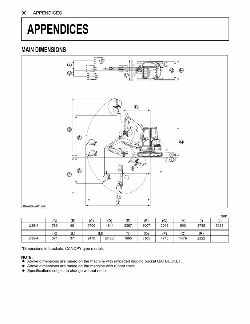
90 APPENDICES
APPENDICES
MAIN DIMENSIONS*Dimensions in brackets: CANOPY type models
A Above dimensions are based on the machine with unloaded digging bucket Q/C BUCKET.A Above dimensions are based on the machine with rubber track.A Specifications subject to change without notice.
mm(A) (B) (C) (D) (E) (F) (G) (H) (I) (J)
U35-4 789 481 1700 4844 3397 3007 2013 900 3735 5281
(K) (L) (M) (N) (O) (P) (Q) (R)U35-4 371 371 2470 [2480] 1695 5165 4745 1479 2222
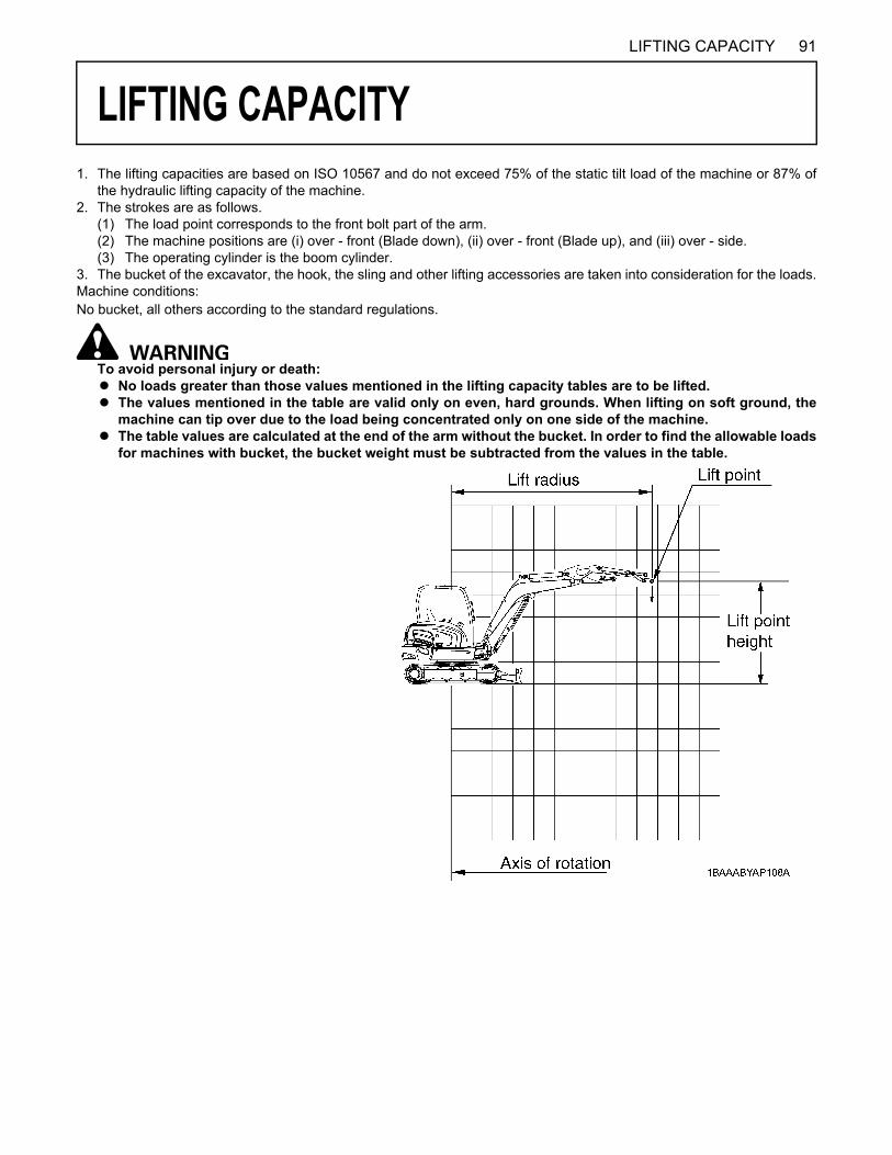
91LIFTING CAPACITY
LIFTING CAPACITY
1. The lifting capacities are based on ISO 10567 and do not exceed 75% of the static tilt load of the machine or 87% ofthe hydraulic lifting capacity of the machine. 2. The strokes are as follows.
(1) The load point corresponds to the front bolt part of the arm. (2) The machine positions are (i) over - front (Blade down), (ii) over - front (Blade up), and (iii) over - side. (3) The operating cylinder is the boom cylinder.
3. The bucket of the excavator, the hook, the sling and other lifting accessories are taken into consideration for the loads.Machine conditions:No bucket, all others according to the standard regulations.
To avoid personal injury or death:A No loads greater than those values mentioned in the lifting capacity tables are to be lifted. A The values mentioned in the table are valid only on even, hard grounds. When lifting on soft ground, the
machine can tip over due to the load being concentrated only on one side of the machine. A The table values are calculated at the end of the arm without the bucket. In order to find the allowable loads
for machines with bucket, the bucket weight must be subtracted from the values in the table.
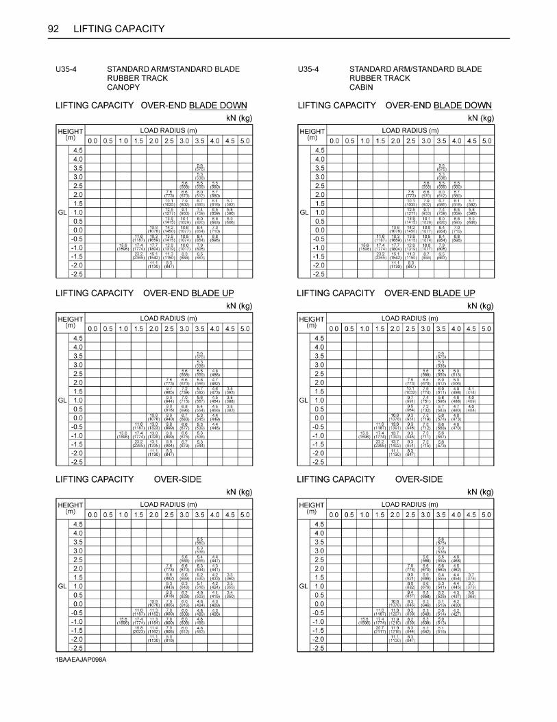
92 LIFTING CAPACITY

93LIFTING CAPACITY
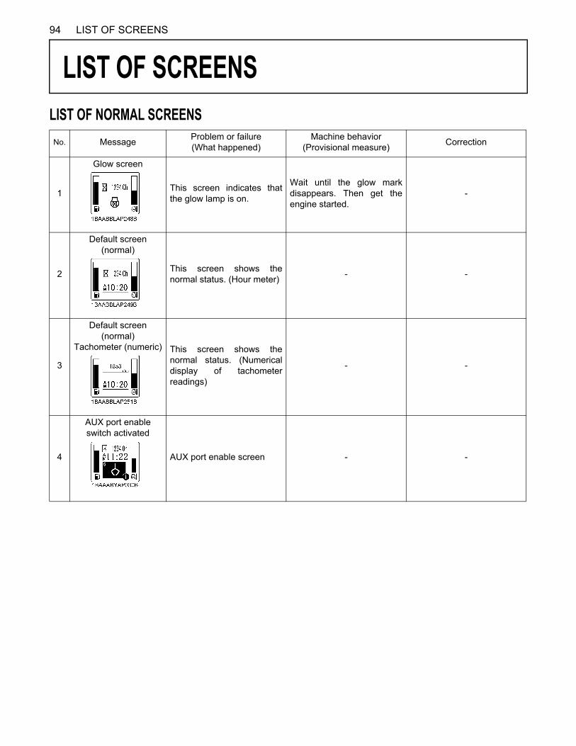
94 LIST OF SCREENS
LIST OF SCREENS
LIST OF NORMAL SCREENSNo. Message Problem or failure(What happened)Machine behavior
(Provisional measure) Correction
1
Glow screen
This screen indicates thatthe glow lamp is on.
Wait until the glow markdisappears. Then get theengine started.
-
2
Default screen (normal)
This screen shows thenormal status. (Hour meter) - -
3
Default screen (normal)
Tachometer (numeric) This screen shows thenormal status. (Numericaldisplay of tachometerreadings)
- -
4
AUX port enable switch activated
AUX port enable screen - -
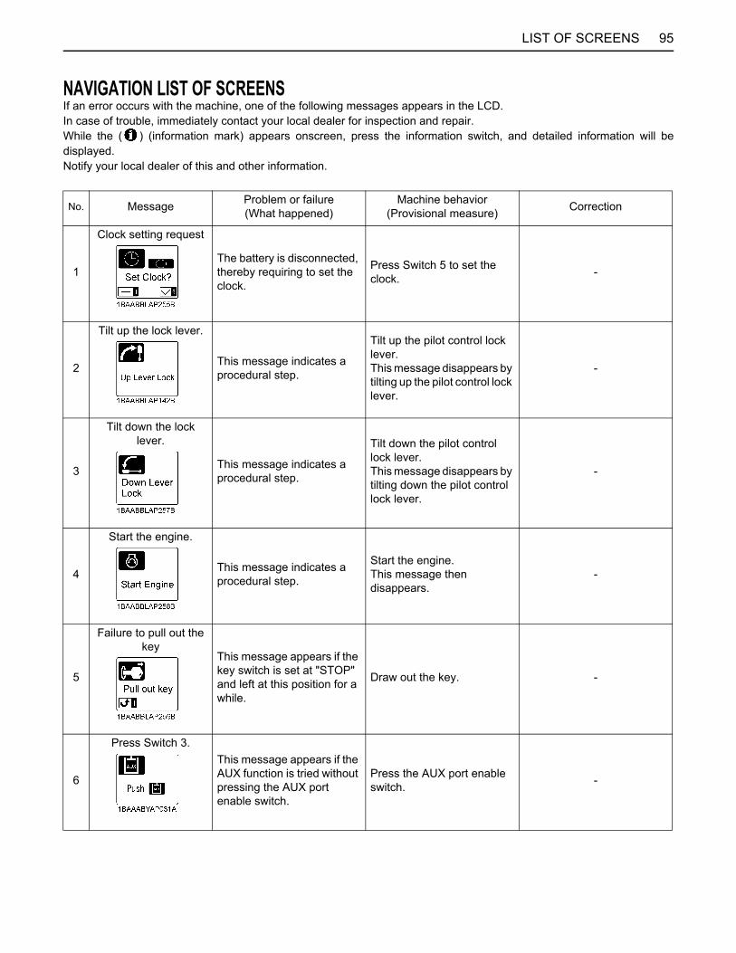
95LIST OF SCREENS
NAVIGATION LIST OF SCREENSIf an error occurs with the machine, one of the following messages appears in the LCD.In case of trouble, immediately contact your local dealer for inspection and repair. While the ( ) (information mark) appears onscreen, press the information switch, and detailed information will bedisplayed.Notify your local dealer of this and other information.
No. Message Problem or failure(What happened)
Machine behavior(Provisional measure) Correction
1
Clock setting request
The battery is disconnected, thereby requiring to set the clock.
Press Switch 5 to set the clock. -
2
Tilt up the lock lever.
This message indicates a procedural step.
Tilt up the pilot control lock lever.This message disappears by tilting up the pilot control lock lever.
-
3
Tilt down the lock lever.
This message indicates a procedural step.
Tilt down the pilot control lock lever.This message disappears by tilting down the pilot control lock lever.
-
4
Start the engine.
This message indicates a procedural step.
Start the engine.This message then disappears.
-
5
Failure to pull out the key
This message appears if the key switch is set at "STOP" and left at this position for a while.
Draw out the key. -
6
Press Switch 3.This message appears if the AUX function is tried without pressing the AUX port enable switch.
Press the AUX port enable switch. -

96 LIST OF SCREENS
7
Not equipped with overload warning
function This message appears if the overload warning switch is pressed on machines not equipped with overload warning system.
- -
8
Out of fuel
Fuel is running out. - Add fuel.
9
Fuel sensor error
The fuel sensor system is in trouble.
The fuel level indicator does not appear on the meter.Press the display selector switch, and the normal display is switched back.The machine's other functions are still operative.
Immediately contact your local dealer.
10
Charging system error
Charging system is in trouble.The battery is not charging.
The machine works until the battery goes dead.
Immediately contact your local dealer.
11
Engine oil pressure error
The engine lubricating system oil pressure is too low. Stop the engine.
The engine may get burnt out. Immediately stop the engine.
Immediately contact your local dealer.
12
Overvoltage This message appears if a jumper cable is connected to a 24V battery or improper device to get the engine started or if the alternator is in trouble.
Immediately interrupt the engine if with a 24V battery. When the engine gets restarted and is running with no message appearing, it means there is no problem.
If this message still appears, immediately ask for repair.
13
Overheat advance warning
Water temperature rising Water temperature is rising
somewhat higher than specified.
Operate with the load a little lessened.Check the radiator and other components for clog. Immediately clean them up.
No. Message Problem or failure(What happened)
Machine behavior(Provisional measure) Correction

97LIST OF SCREENS
14
Cool-down during overheat idling
The engine automatically reduces rpm's to avoid an overheat.
Leave the engine idling until this warning disappears.Do not stop the engine because the coolant temperature will increase sharply and may boil and gush out. Be sure to cool down the engine without stopping it.
Refill the radiator with coolant by the amount that overflowed amount. Unclog the radiator and other components before use again.Check also the hydraulic system for oil leak and other troubles.If an oil leak is found, immediately contact your local dealer for repair.
15
Water temperature sensor error
Water temperature sensor system is in trouble.
The meter does not show water temperature.Press the display selector switch, and the normal display is switched back.The machine's other functions are operative, but an overheat and other problems cannot be detected.
Immediately contact your local dealer.
16
Lock lever system error
The lock lever system is in trouble.
The engine can run, but the machine fails to move.
Immediately contact your local dealer.
17
Travel 2-speed system (switching)
The 2-speed switching system is in trouble.
The machine still runs at low speed without switching to high speed.The machine's other functions are still operative.
Immediately contact your local dealer.
18
AI system error
The auto idle system is in trouble.The accelerator fails too.
The accelerator fails, but the machine's other functions are still operative.Move the machine to a place suited for repair.
Immediately contact your local dealer.
19
5V short-circuit
The sensor's 5V power supply is short-circuited.
The majority of systems fail.* The engine may get started and the machine may move. But do not try any jobs.(Just move the machine to a safe place.)
Immediately contact your local dealer.
No. Message Problem or failure(What happened)
Machine behavior(Provisional measure) Correction

98 LIST OF SCREENS
No. Message Problem or failure(What happened)
Machine behavior(Provisional measure) Correction
20
12V short-circuit
The sensor's or switch's 12V line is short-circuited.
The majority of systems fail.* The engine may start and the machine may move. But do not try any jobs.(Just move the machine to a safe place.)
Immediately contact your local dealer.
21
CAN system errorThe communication (CAN) system is in trouble. Some meter readings may be erroneous or some switches may malfunction.
The engine may get started and the machine may move. But do not try any jobs.(Just move the machine to a safe place.)
Immediately contact your local dealer.
22
General switching system error The general switching
system is in trouble.(This message appears only when the general switching function is preset effective.)
The engine can get restarted and the machine can move, but the general switching system fails.When the other systems than the general switching system function, the job can be continued.
Immediately contact your local dealer.
23
AUX1 port system error
The AUX1 port system is in trouble.
The engine can get restarted and the machine can move, but the AUX1 port system fails.When the other systems than the AUX1 port system function, the job can be continued.
Immediately contact your local dealer.
24
Thumb system error
The Thumb system is in trouble.
The engine can get restarted and the machine can move, but the Thumb system fails.When the other systems than the Thumb and AUX port system function, the job can be continued.
Immediately contact your local dealer.
25
Periodic check (advance notice)
This message appears 10 hours before the periodic check interval.Press the information switch, and the list of related components can be reviewed.
Get the engine started as usual.
Ask your local dealer for relevant part and replace the existing part with it. After replacement, turn on and off the key 10 times, and this message disappears.
26
Periodic check (warning) The periodic check interval
has passed.Press the information switch, and the list of related components can be reviewed.
The engine can still get started, but immediately ask your local dealer for replacement.
Ask your local dealer for relevant part and replace the existing part with it. After replacement, turn on and off the key 10 times, and this message disappears.