operator's manual - kubota.com.au · manual and on labels on the machine itself to warn of the...
TRANSCRIPT
L4600MODEL
OPERATOR'S MANUAL
1AGAPBYAP0010English (Oceania)Code No. TC437-5971-1
L4600
© KUBOTA Corporation 2012
READ AND SAVE THIS MANUAL
1205-1149
1205-1149
KUBOTA Corporation is ···Since its inception in 1890, KUBOTA Corporation has grown to rank as one of the major firms in Japan.
To achieve this status, the company has through the years diversified the range of its products and services to a remarkable extent. Nineteen plants and 16,000 employees produce over 1,000 different items, large and small.
All these products and all the services which accompany them, however, are unified by one central commitment. KUBOTA makes products which, taken on a national scale, are basic necessities. Products which are indispensable. Products which are intended to help individuals and nations fulfill the potential inherent in their environment. KUBOTA is the Basic Necessities Giant.
This potential includes water supply, food from the soil and from the sea, industrial development, architecture and construction, and transportation.
Thousands of people depend on KUBOTA's know-how, technology, experience and customer service. You too can depend on KUBOTA.
L4600AQ. F. 1-1. -. K

Thank you very much for choosing the L series tractor.This operator's manual covers the operation, inspection and preventivemaintenance instructions that is specific to the oceania models. For otherinformation and instructions, refer to the separately issued operator's manual forthe sister model. (L series tractor)Please read both manuals carefully, to operate the machine properly and safely.Proper daily inspection, servicing and lubrication keeps your machine in goodcondition.
This symbol, the industry's "Safety Alert Symbol", is used throughout thismanual and on labels on the machine itself to warn of the possibility of personalinjury. Read these instructions carefully. It is essential that you read theinstructions and safety regulations before you attempt to assemble or use thisunit.
DANGER : Indicates an imminently hazardous situation which, if notavoided, will result in death or serious injury.
WARNING : Indicates a potentially hazardous situation which, if notavoided, could result in death or serious injury.
CAUTION : Indicates a potentially hazardous situation which, if notavoided, may result in minor or moderate injury.
IMPORTANT : Indicates that equipment or property damage could result ifinstructions are not followed.
NOTE : Gives helpful information.
FOREWORD
SAFETY FIRST

CONTENTS
SAFE OPERATION ................................................................................................. 1SPECIFICATIONS....................................................................................................... 1SPECIFICATION TABLE ......................................................................................... 1TRAVELING SPEEDS ............................................................................................. 3
INSTRUMENT PANEL AND CONTROLS................................................................... 4
OPERATING THE TRACTOR..................................................................................... 5STARTING............................................................................................................... 5
Head Light Switch............................................................................................................. 5Turn Signal / Hazard Light Switch .................................................................................... 5Horn Button....................................................................................................................... 5Tractor Lights.................................................................................................................... 6Electrical Outlet.................................................................................................................6
THREE-POINT HITCH & DRAWBAR.......................................................................... 7DRAWBAR............................................................................................................... 7
Adjusting Drawbar Length ................................................................................................ 7
PERIODIC SERVICE................................................................................................... 8SERVICE AS REQUIRED........................................................................................ 8
Replacing Fuse.................................................................................................................8Replacing Light Bulb......................................................................................................... 8
1SAFE OPERATION
SAFE OPERATION
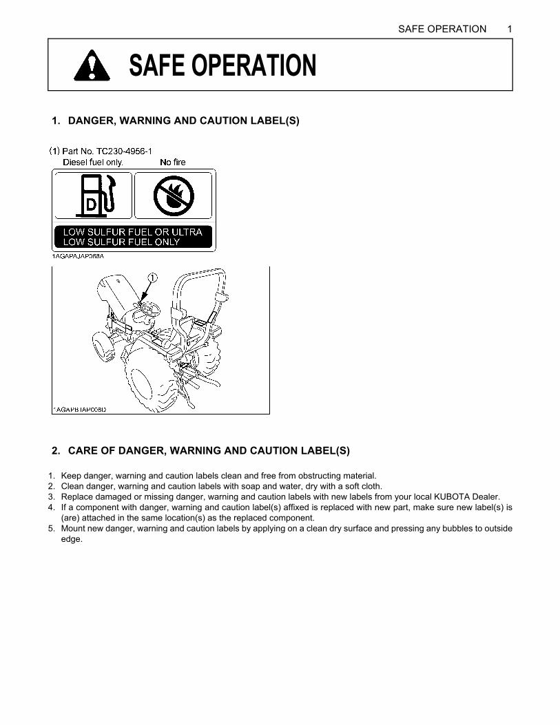
1. Keep danger, warning and caution labels clean and free from obstructing material.2. Clean danger, warning and caution labels with soap and water, dry with a soft cloth.3. Replace damaged or missing danger, warning and caution labels with new labels from your local KUBOTA Dealer.4. If a component with danger, warning and caution label(s) affixed is replaced with new part, make sure new label(s) is
(are) attached in the same location(s) as the replaced component.5. Mount new danger, warning and caution labels by applying on a clean dry surface and pressing any bubbles to outside
edge.
1. DANGER, WARNING AND CAUTION LABEL(S)
2. CARE OF DANGER, WARNING AND CAUTION LABEL(S)
1SPECIFICATIONS
SPECIFICATIONS
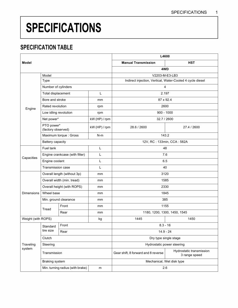
SPECIFICATION TABLEModel
L4600
Manual Transmission HST
4WD
Engine
Model V2203-M-E3-LB3Type Indirect injection, Vertical, Water-Cooled 4 cycle diesel
Number of cylinders 4
Total displacement L 2.197
Bore and stroke mm 87 x 92.4
Rated revolution rpm 2600
Low idling revolution rpm 900 - 1000
Net power* kW (HP) / rpm 32.7 / 2600
PTO power* (factory observed)
kW (HP) / rpm 28.6 / 2600 27.4 / 2600
Maximum torque : Gross N-m 143.2
Battery capacity 12V, RC : 133min, CCA : 582A
Capacities
Fuel tank L 48
Engine crankcase (with filter) L 7.6
Engine coolant L 6.5
Transmission case L 40
Dimensions
Overall length (without 3p) mm 3120
Overall width (min. tread) mm 1585
Overall height (with ROPS) mm 2330
Wheel base mm 1845
Min. ground clearance mm 385
TreadFront mm 1155
Rear mm 1180, 1200, 1300, 1450, 1545
Weight (with ROPS) kg 1445 1450
Travelingsystem
Standard tire size
Front 8.3 - 16
Rear 14.9 - 24
Clutch Dry type single stage
Steering Hydrostatic power steering
Transmission Gear shift, 8 forward and 8 reverse Hydrostatic transmission3 range speed
Braking system Mechanical, Wet disk type
Min. turning radius (with brake) m 2.6

2 SPECIFICATIONS
NOTE: *Manufacturer's estimate The company reserves the right to change the specifications without notice.
Model
L4600
Manual Transmission HST
4WD
Hydraulic unit
Hydraulic control system Position control
Pump capacity L / min 29.4
Three point hitch Category 1
Max. lift force
At lift points kg 1300
24 in. behind lift points
kg 1053
System pressure MPa (kgf / cm ) 17.7 (180)
PTORear PTO SAE 1-3/8, 6-splines
PTO / Engine speed rpm 540 / 2475 540 / 2640
3SPECIFICATIONS
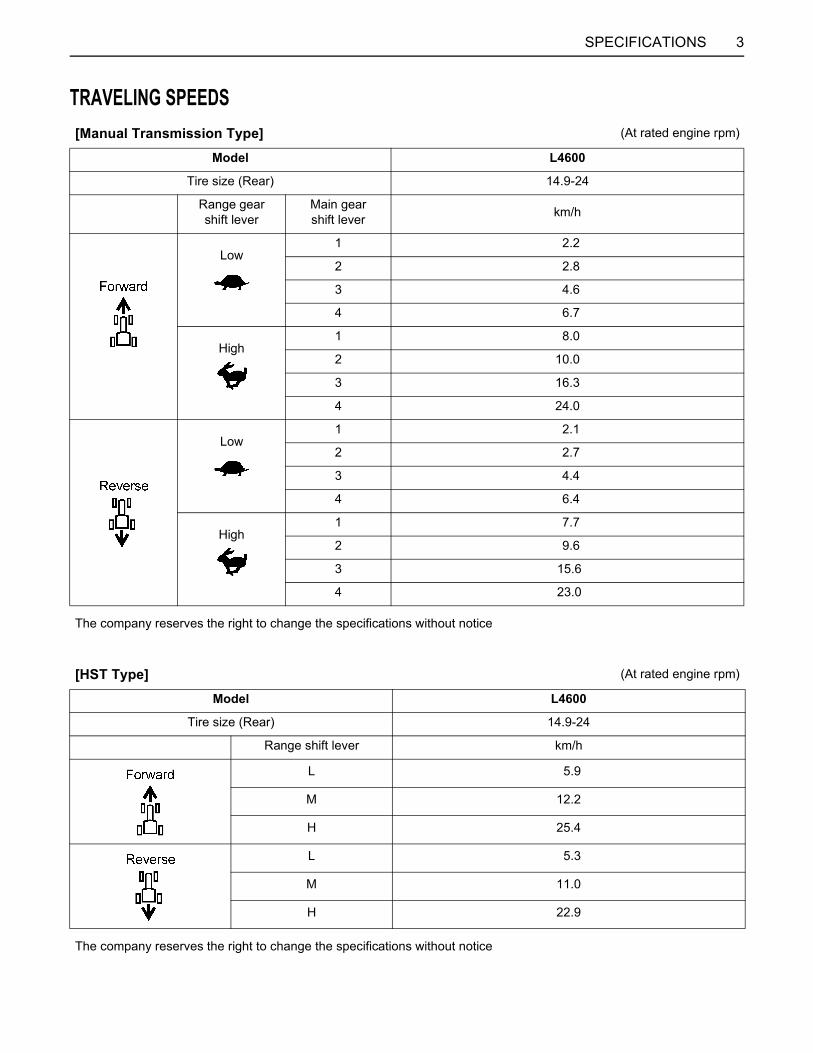
TRAVELING SPEEDS[Manual Transmission Type] (At rated engine rpm)
Model L4600
Tire size (Rear) 14.9-24
Range gearshift lever
Main gearshift lever km/h
Low1 2.2
2 2.8
3 4.6
4 6.7
High1 8.0
2 10.0
3 16.3
4 24.0
Low1 2.1
2 2.7
3 4.4
4 6.4
High1 7.7
2 9.6
3 15.6
4 23.0
The company reserves the right to change the specifications without notice
[HST Type] (At rated engine rpm)
Model L4600
Tire size (Rear) 14.9-24
Range shift lever km/h
L 5.9
M 12.2
H 25.4
L 5.3
M 11.0
H 22.9
The company reserves the right to change the specifications without notice
4 INSTRUMENT PANEL AND CONTROLS
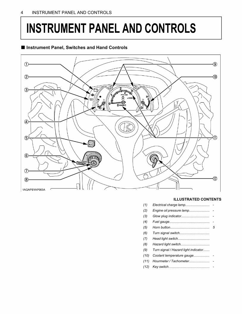
INSTRUMENT PANEL AND CONTROLS
B Instrument Panel, Switches and Hand ControlsILLUSTRATED CONTENTS(1) Electrical charge lamp.......................... -
(2) Engine oil pressure lamp...................... -
(3) Glow plug indicator.............................. -
(4) Fuel gauge........................................... -
(5) Horn button.......................................... 5
(6) Turn signal switch................................
(7) Head light switch..................................
(8) Hazard light switch...............................
(9) Turn signal / Hazard light indicator.......
(10) Coolant temperature gauge................. -
(11) Hourmeter / Tachometer...................... -
(12) Key switch............................................ -

5OPERATING THE TRACTOR
OPERATING THE TRACTOR
STARTINGBHead Light SwitchTurn the light switch clockwise, and the following lights areactivated on the switch position.BTurn Signal / Hazard Light SwitchC Turn Signal Light SwitchTo indicate a right turn, turn the turn signal light switchclockwise. To indicate a left turn, turn the turn signal lightswitch counter-clockwise. The corresponding right andleft turn signal lights and indicator on the instrument panelwill flash. Turn signal is active when key switch is in the"ON" position.
A Be sure to return switch to center position after turning.
C Hazard Light SwitchWhen hazard light switch is pushed, the hazard lightsflash along with the indicator on the instrument panel.Press the hazard light switch again to turn off the light.
BHorn ButtonThe horn will sound when the key switch is in the "ON"position and the horn button pressed.
(1) Head light switch
Light nameSwitch Position
Head light (Low beam) OFF ON ---
Head light (High beam) OFF --- ON
Tail light OFF ON ON
(1) Turn signal light switch(2) Hazard light switch(3) Hazard / Turn signal indicator
(1) Horn button (A) "PUSH"

OPERATING THE TRACTOR6
BTractor Lights(1) Head light(2) Side turn signal / Hazard light(3) Tail light(4) Rear turn signal / Hazard light(5) Brake stop light
BElectrical OutletAn electrical outlet is supplied for use with front loader.
To avoid personal injury:A When using the power takeout, do not use the
convex connector. When not using the powertakeout, connect the convex connector.
(1) Front loader 3rd function solenoid valve : Green

7THREE-POINT HITCH & DRAWBAR
THREE-POINT HITCH & DRAWBAR
DRAWBARTo avoid personal injury:A Never pull from the top link, the rear axle or any
point above the drawbar. Doing so could causethe tractor to tip over rearward causingpersonal injury or death.
BAdjusting Drawbar LengthWhen towing an implement, recommend use of (B) hole indrawbar.The drawbar load is referred to "IMPLEMENTLIMITATIONS" section of the separately issued manual.
(1) PTO shaft(2) Drawbar(3) Drawbar pin
Holes : (A),(B)

8 PERIODIC SERVICE
PERIODIC SERVICE
SERVICE AS REQUIREDBReplacing FuseThe tractor electrical system is protected from potentialdamage by fuses.A blown fuse indicates that there is an overload or shortsomewhere in the electrical system.If any of the fuses should blow, replace with a new one ofthe same capacity.A Before replacing a blown fuse, determine why the fuseblew and make any necessary repairs. Failure tofollow this procedure may result in serious damage tothe tractor electrical system. Refer to the"TROUBLESHOOTING" section of the separatelyissued manual or your local KUBOTA Dealer forspecific information dealing with electrical problems.
BReplacing Light Bulb1. Head light and rear combination lights :
Take the bulb out of the light body and replace with anew one.
2. Other lights :Detach the lens and replace the bulb.
FUSE No. CAPACITY(A) Protected circuit(1) 15 Hazard(2) 5 Work light(3) 5 Panel(4) 15 Head light(5) 5 OPC CONTROLLER(6) 5 Glow lamp(7) 10 Brake lamp(8) 10 Electrical outlet(9) 50 Main
(10) 40 Key stop(11) 40 Key switch
Light Capacity
Head light 25 W / 25 W
Tail light 5 W
Turn signal / Hazard light (rear) 21 W
Turn signal / Hazard light (front) 23 W
Instrument panel light 1.7 W
Brake stop light 21 W