final group
TRANSCRIPT

The Design of an Automatic
Watch Winder
By
Mark Baxter
Numan Anwar
Ross Haig
Thomas Clark
William Duncan
This project is submitted as partial fulfilment for the Honours degree of
Bachelor of Engineering in
Product Design and Development
At the University of the West of Scotland
School of Engineering, Numan Anwar (B00209077) _______________
University of the West of Scotland, Mark Baxter (B00136110) _______________
High Street, Thomas Clark (B00215314) _______________
Paisley, William Duncan (B00207244) _______________
PA1 2BE Ross Haig (B00219522) _______________

i
Acknowledgements
The group would like to thank the following people for their help and contribution throughout
the year:
Dr Bob Bailey (Supervisor)
David Towert (Lecturer)
Robert Boyce (Chief Technician)
George (Technician)
Allister (Technician)
…with special thanks to the technical staff of UWS.
ii
Abstract
The following report details the methods and suitability of recharging an automatic watch
through the use of a watch winder. It has been found that because of different automatic
watch types the winder should be able to rotate in more than one direction, capable of
charging each type of automatic watch. Through extensive research on watches and watch
winders an understanding of the watches functionality led to the creation of two models
capable of winding one watch each. The two prototypes were engineered focusing mainly on
the functionality, aesthetics and ergonomics.
Having understood what was necessary for a watch winder to be successful, a design
specification was created. This allowed multiple conceptual ideas to be created to select the
most aesthetically pleasing design with the most effective functionality. The best ideas from
each design were taken forward until two designs were selected and developed.
The designs were used to manufacture two prototypes. Components were chosen for each
design which were assembled to the 3D printed shelled bodies. The assembly process was
carried out carefully ensuring that each component would work to their fullest potential and
creating a long lasting and successful prototype. Through coding, controller boards would
control the components within the prototypes creating the motion required to wind an
automatic watch. The prototypes were finalised and tested.
Despite issues that occurred during the assembly stage, simple yet planned solutions were
used to allow the prototypes to have the same functionality as what was designed.
The finalised prototypes and recommendations for further work were discussed in detail to
ensure that the real manufactured models would be even more successful than the prototypes.

iii
Copyright
“The copyright of this dissertation rests with the author. No quotation from it should be
published without his prior written consent and information derived from it should be
acknowledged.”

iv
Table of Contents
Acknowledgements ..................................................................................................................... i
Abstract ...................................................................................................................................... ii
Copyright ................................................................................................................................. iii
Table of Contents ...................................................................................................................... iv
Nomenclature ........................................................................................................................... vii
List of Figures ........................................................................................................................ viii
List of Tables ............................................................................................................................. x
1. Introduction ............................................................................................................................ 1
1.1 Background and Context.................................................................................................. 1
1.2 Brief ................................................................................................................................. 2
2. Literature Review................................................................................................................... 3
2.1 Research into Automatic Watches ................................................................................... 3
2.2 Research on Watch Winders ............................................................................................ 5
2.3 Internal Mechanics Study ................................................................................................ 7
3. Initial Designs ........................................................................................................................ 9
3.1 Product Design Specification ........................................................................................... 9
3.1.1 Function .................................................................................................................... 9
3.1.2 Material requirements ............................................................................................... 9
3.1.3 Size of Product .......................................................................................................... 9
3.1.4 Storage .................................................................................................................... 10
3.1.5 Cleaning and Maintenance ...................................................................................... 10
3.1.6 Aesthetics ................................................................................................................ 10
3.1.7 Quality..................................................................................................................... 10
3.1.8 Safety ...................................................................................................................... 10
3.1.9 Cost ......................................................................................................................... 11
3.1.10 Manufacturing ....................................................................................................... 11

v
3.1.11 Legal or Patents..................................................................................................... 11
3.1.12 Disposal................................................................................................................. 11
3.1.13 Competition and Target Market ............................................................................ 11
3.2 Morphological Chart ...................................................................................................... 12
3.3 Design Concepts ............................................................................................................ 14
3.3.1 Concept 1 – Slab ..................................................................................................... 14
3.3.2 Concept 2 – Bowl.................................................................................................... 15
3.3.3 Concept 3 – Gears ................................................................................................... 16
3.3.4 Concept 4 – Case .................................................................................................... 17
3.3.5 Concept 5 – Clock ................................................................................................... 18
3.4 Convergence Matrix....................................................................................................... 19
3.5 Final Design Choice ....................................................................................................... 20
4. Development ........................................................................................................................ 21
4.1 Standards for Watch Sizes ............................................................................................. 21
4.2 Methods of Movement ................................................................................................... 23
4.3 Design and Basic Dimensions ....................................................................................... 24
5. Designs ................................................................................................................................. 28
5.1 Parts Lists ....................................................................................................................... 28
5.2 3DS Max Renders .......................................................................................................... 32
6. Prototyping ........................................................................................................................... 33
6.1 3D Printing ..................................................................................................................... 33
6.1.1 Stratasys Dimension ABS Printer ........................................................................... 34
6.2 Assembly of the Watch Winders ................................................................................... 36
6.3 Programming.................................................................................................................. 40
6.3.1. Gyro Bowl and Slab Coding .................................................................................. 41
6.4 Testing............................................................................................................................ 44
7. Discussion and Reflection.................................................................................................... 45
vi
8. Conclusion ........................................................................................................................... 49
9. Recommendations for Future Work..................................................................................... 50
9.1 Possible Manufacture ..................................................................................................... 51
Bibliography ............................................................................................................................ 53
Bibliography ............................................................................................................................ 53
Appendix 1 – Drawings ........................................................................................................... 55
Bowl Design......................................................................................................................... 55
Slab Design .......................................................................................................................... 61
Appendix 2 – Code .................................................................................................................. 67
Bowl Code ........................................................................................................................... 67
Slab Code ............................................................................................................................. 69
Appendix 3 – 3DS Max Renders ............................................................................................. 71
Clay Renders ........................................................................................................................ 71
Final Renders ....................................................................................................................... 72
Appendix 4 – Miscellaneous .................................................................................................... 73

vii
Nomenclature
Symbols
sec Second
min Minute
hr Hour
mm Millimetre
° Degree
dia Diameter
£ Pounds
$ Dollars
Acronyms
UWS University of the West of Scotland
PDS Product Design Specification
ABS Acrylonitrile Butadiene Styrene
USB Universal Serial Bus
CAD Computer Aided Design
CAM Computer Aided Manufacturing
3D Three Dimensional
CNC Computer Numerical Control
NC Numerical Control
UV Ultra Violet
STL Stereo lithography
AC Alternating Current
DC Direct Current
V Voltage
LED Light Emitting Diode
VMC Vertical Machining Centres

viii
List of Figures
Figure 1 - Flywheel .................................................................................................................... 7
Figure 2 – Flywheel Movement ................................................................................................. 7
Figure 3 – Slab Conceptual Drawing ....................................................................................... 14
Figure 4 – Bowl Conceptual Drawing ..................................................................................... 15
Figure 5 – Gear Conceptual Drawing ...................................................................................... 16
Figure 6 – Case Conceptual Drawing ...................................................................................... 17
Figure 7 – Clock Conceptual Drawing .................................................................................... 18
Figure 8 – Face Sizes ............................................................................................................... 22
Figure 9 – Watch Length ......................................................................................................... 22
Figure 10 – Watch Thickness .................................................................................................. 23
Figure 11 – Watch Holder Models ........................................................................................... 25
Figure 12 – Gyroscopic Ring Models ...................................................................................... 26
Figure 13 – Drive Models ........................................................................................................ 26
Figure 14 – In Progress Modelling .......................................................................................... 27
Figure 15 – Fully Assembled Models ...................................................................................... 28
Figure 16 – Dual Clay Render ................................................................................................. 32
Figure 17 – 3D Printer ............................................................................................................. 33
Figure 18 – Soldering............................................................................................................... 37
Figure 19 - Failure ................................................................................................................... 46
Figure 20 – Bowl Attachment Drawing ................................................................................... 55
Figure 21 – Bowl Half Drawing .............................................................................................. 56
Figure 22 – Complete Assembly Drawing............................................................................... 57
Figure 23 – Cover Drawing ..................................................................................................... 58
Figure 24 – Ring Assembly Drawing ...................................................................................... 59
Figure 25 – Motor Vice Drawing............................................................................................. 60
Figure 26 – Back Panel Drawing ............................................................................................. 61
Figure 27 – Base Drawing ....................................................................................................... 62
Figure 28 – Shaft Drawing ....................................................................................................... 63
Figure 29 – Cradle Drawing .................................................................................................... 64
Figure 30 – Front Panel Drawing............................................................................................. 65
Figure 31 – Full Assembly Drawing ........................................................................................ 66
Figure 32 – Slab Clay Render .................................................................................................. 71

ix
Figure 33 – Bowl Clay Render ................................................................................................ 71
Figure 34 – Final Render GyroSlab ......................................................................................... 72
Figure 35 – Final Render GyroBowl ....................................................................................... 72
Figure 36 – GRIPS Meeting Sheet........................................................................................... 73
Figure 37 – Completed Risk Assessment ................................................................................ 74

x
List of Tables
Table 1 – Morphological Chart ................................................................................................ 13
Table 2 – Convergence Matrix ................................................................................................ 19
Table 3 – Parts List (Slab) ....................................................................................................... 29
Table 4 – Parts List (Bowl) ...................................................................................................... 30
Table 5 – Slab Design Print Times .......................................................................................... 35
Table 6 – Bowl Design Print Times ......................................................................................... 35
1
1. Introduction
This report presents a design for a watch winder. The design of this watch winder is to use bi-
directional rotational movement which means that the automatic watch will be rotating clock-
wise and then counter clock-wise to power (keep time) for the watch.
1.1 Background and Context
A watch winder is a device used to keep automatic (also known as self-winding)
watches running when not worn. The automatic watch is powered with the movement
of the user of the watch.
Automatic watches operate on the principle of winding themselves using a moving
weight inside the watch. The weight swings or rotates while the watch is worn and
turns the winding mechanism inside the watch. So, if the watch is not worn, then it no
longer receives power this way and will run out of power. While virtually all
automatic watches can be manually wound, this is not always convenient. So the
concept of an automatic watch winder was born.
A watch winder is a device which holds an automatic watch and moves it in a circular
pattern to emulate the necessary parts of human motion to operate the self-winding
mechanism.
A watch winder cannot over wind an automatic watch, since all automatic watches are
protected from being over wound by a mechanism that disengages the winding
process when the mainspring is fully wound. Using a timer-based winder is still very
important to prevent excessive wear on the winding mechanism. There is no need to
keep the watch in motion 24 hours a day when usually only 30 minutes of motion is
necessary to keep it properly wound.
Winders are totally unnecessary and useless with battery-operated quartz watches. But
they do work for the special 'battery-less' quartz watches, such as the Omega-Matic,
Seiko Kinetic, and similar. These automatic/quartz hybrids use the same weight/rotor
principal to generate electric power to run a quartz movement.
2
The design of the watch winder had one main objective. This objective was to keep
time for the automatic watch by moving it in a bi-directional rotation. Included in this
design objective, was the task of creating the bi-directional rotational movement and
powering the watch winder so it will function/ keep time for the automatic watch.
This report presents the procedures for designing the watch winder for the automatic
watch and to communicate whether the design of the watch winder charges the
automatic watch.
1.2 Brief
The brief provided by the client was as follows:
Title: “Design and Manufacture of an Automatic Watch – Watch Winder”
This project requires a mechanism to be designed, manufactured and tested suitable
for winding an automatic watch while it is not being worn. It must be ergonomically
and aesthetically pleasing, suitable for a dressing table top.

3
2. Literature Review
Prior to any design assignment a certain amount of research is required. In this case since the
client has requested a winding device capable of keeping an automatic watch wound for long
periods of time whilst the watch is not worn the research was conducted on the type of watch
stated in the brief mainly 'Automatic' or 'Self Winding Watches'.
2.1 Research into Automatic Watches
Watches come in plenty of variations to suit the customer ergonomically and through
their personal choice of aesthetics. The way in which a watch works is also varied.
This can range from a battery powered watch to a mechanical watch which is wound
up manually by hand. The automatic watch allows the user to keep the watch charging
while it is being worn. The user should not have to manually charge up the watch.
Because of this the automatic watch tends to be a more expensive watch.
The price range for automatic watches can range from £100 to £10,000 and above
depending on the make of watch. Certain limited edition watches can sell for over
£1,000,000. All large watch distributors such as Omega and Rolex sell automatic
watches. These watches have been designed with every potential customer in mind
creating a range of watches suitable for men, woman and children of all sizes and
ages. Therefore watches are available with different sized faces to suit the wrist in
which it will be worn. As a watch is an appreciated and valuable item, selecting the
perfect watch is an imperative decision. Each watch type will suit the individual
deciding on a new watch.
“Knowing how each movement works can help you decide which movement you
would like in your next timepiece” (Edwards, 2010).
A basic understanding of each watch type and its functionality will allow the
customer to choose the perfect watch for the individual’s taste and lifestyle. A quartz
watch is battery powered and will therefore keep the time to within a minute of the
initial set time by the end of a year. With an automatic or manual watch, however, the
time will gain or lose a few minutes in a month which will need reset.

4
The benefit of an automatic watch is that if the watch is worn everyday then it will
remain fully charged. Most watch manufacturers require the watch to be wound 850-
1200 turns per day which will be easily attainable during an average day. Automatic
watches, however, will stop running after 1-2 days of sitting stationary. A Quartz
watch’s battery will need replaced after 18 months of use whereas a manual watch
will have to be wound up by the crown every day to guarantee full charge.
For an individual who does not have a collection of watches and tends to wear one
watch, the Automatic watch will be the best suited as it is self-winding and is an
ageless product. Watches after all can carry on through generations and do not look
out of date.
“That is why Rolex became, in 1985, the first watchmaking brand to use 904L steel, a
highly corrosion-resistant alloy that acquires an exceptional sheen when polished”
(Rolex, 2015).
To guarantee that a watch does not age the material selection is vital. Watches are
worn daily and will experience countless knocks and scratches over its life. Therefore
the strongest and most scratch resistant materials must be selected. These materials
can range from ceramics which can prevent scratches to steels that do not corrode
when facing everyday elements or harsh conditions.
Materials can also be used to increase a watches value and make it more prestigious.
Once an Automatic watch has been removed, however, the watch will lose its charge.
Therefore a watch winder is required to rewind the watch or even keep it charged. By
researching different types of watches focusing on the aesthetics, ergonomics and
differing functions the group was able to use the knowledge gained towards the watch
winder designs.
By designing a product that would be adequate for all types of automatic watch, the
products desirability would increase. This meant that for metal watches that have a
non-adjustable strap, the winder must be capable of holding all sizes of strap and must
be made of a suitable material to prevent scratching or damaging the watch head. The
winder must be designed to wind the watch up between the required amount of turns
while having a movement which will not damage the watch. Therefore understanding
an automatic watches motion is vital for the design process.

5
2.2 Research on Watch Winders
Watch winders come in various shapes and sizes with different primary functions as
the priority when being designed. Some winders have aesthetics as their primary
design purpose while others focus on the quantity of watches that can be held at one
time.
Using articles and researching different winders on the market the most important and
successful winders were found apprehending their reason for success.
From Jason Heaton’s article, “Five Best Watch Winders” (Jason Heaton, 2013) it was
found that the best winders on the market do not have to be expensive to function
effectively. If a watch winder has a distinguished brand name on it then the price of
the winder can be extremely high although the winder’s functionality is just as good
as the next winder.
Watch winders and watches can be a collector’s hobby in which case expensive
winders can be a luxury but for functionality this is not the case. A Versa Compact
Automatic Dual Watch Winder is only £50 although it holds two watches and lets the
user set the direction in which the winder will rotate as Automatic watches have
different winding modes. The winder will rotate for a period of time before stopping
for a certain amount of time. The amount of winds per day can be set by the user to
suit the specific type of watch. This is perfect for any automatic watch and is
extremely cheap for a watch winder.
Watch winders that only hold one watch can cost from £40 to £200,000. “If you really
want to get fancy, you can even purchase a diamond-encrusted single winder for
$400,000” (Jason Heaton, 2013).
The main attraction of the expensive winder types are their materials and aesthetics.
Of course this does not aid in winding the watch but gives the winder a classy finish.
To purchase a winder at such a price for the functionality would be absurd. Watches,
and therefore watch winders, can be bought to show the wealth of an individual and
not be used very often (Ziglar, 2005).
In this webpage, Ziglar makes it clear that the price of a watch winder may be due to
the low production rate.
6
Watch winders are not made on mass production, especially as there are so many
various types for the same functions where variation can only go so far.
For this reason basic watch winders tend to be in the range from £100 to £200,
increasing in price depending on the materials or multiple functions available. To
make the watch winder stand out from the rest the functions must be unique. This is
why some winders have functions which are interesting or not necessary such as a
USB slot. This can also relate to aesthetics.
Certain winders may have the expensive materials but an interesting motion that
winds the watch while being aesthetically pleasing would impress potential customers
(Timp, 2013).
This video shows a homemade gyroscopic watch winder. The frame and rings were
made from plywood while the connecting pins were made of steel and are controlled
by one AC motor with a leather belt connecting the motor to the rings. This simple
design was interesting as well as being aesthetically pleasing. There are many
gyroscopic watch winders on the market although most tend to be rather expensive.
This particular winder was impressive due to its cheap materials yet the functionality
of the winder is excellent. The motion will rotate the watch in all possible directions
necessary for winding the different types of automatic watches available. Not only
was the functionality impressive, the winder was aesthetically pleasing due to the
motion of the rings. It created a mesmerising effect which will catch the majority of
viewer’s attention.
Therefore this simple and cheap winder was successful in the two main selling points
of watch winders, functionality and aesthetics. A watch winder, despite its various
functions and varying price ranges can only be selected by the individual for the
reason that they see best fit. Whether it is for the functionality or purely for the
aesthetics, the individual must be happy with the choice they make for the reason that
they are wanting the winder for.
7
2.3 Internal Mechanics Study
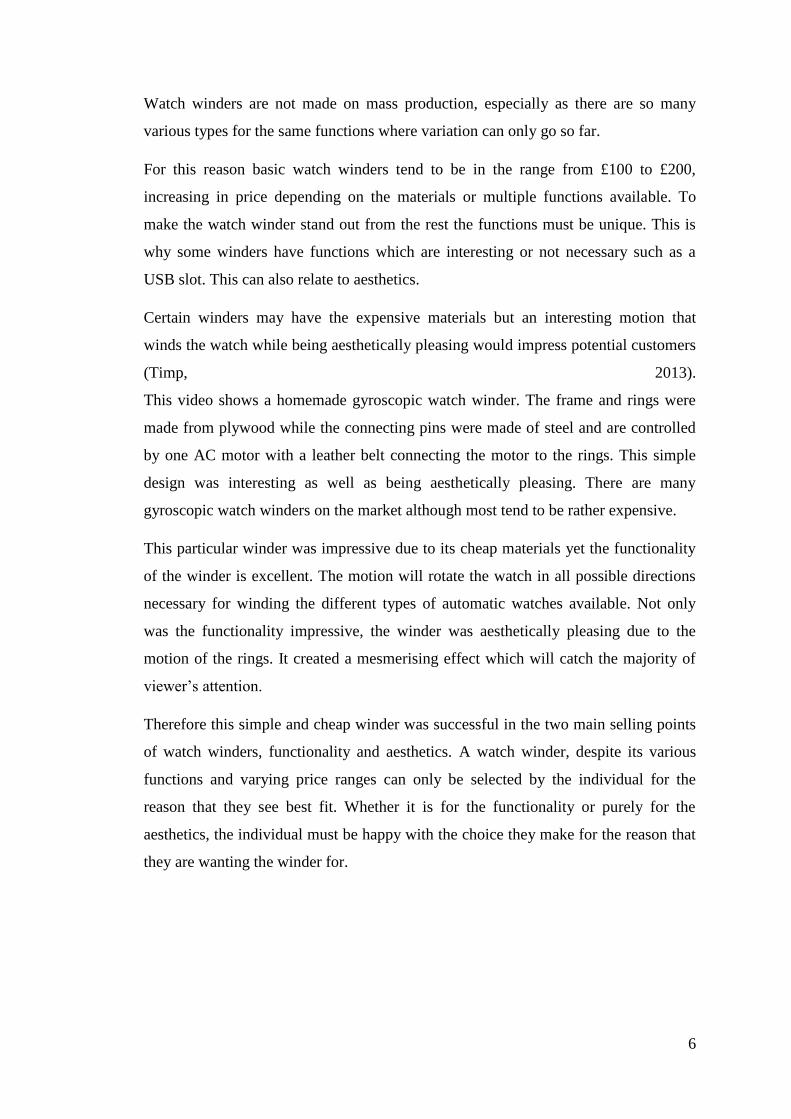
As mentioned the watch relies on a self-winding mechanism to maintain time. The
internal workings of the watch work to transfer the rotational motion of a flywheel
turning with respect to gravity, into stored (potential) energy, this is achieved by
winding a coiled spring at the heart of the watch. The coiled spring is the main source
of power for the watches internal movements. The weighted flywheel is pinned on a
central pivot point on the watch.
Figure 1 - Flywheel
Figure 1 - Flywheel shows a simplified image of the watch. The internal flywheel
which is shaded in grey can be seen, the arrow represents the gravitational pull
towards earth.
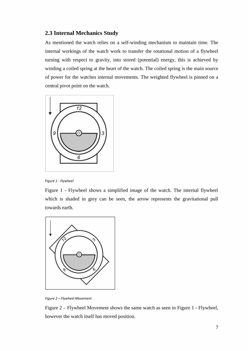
Figure 2 – Flywheel Movement
Figure 2 – Flywheel Movement shows the same watch as seen in Figure 1 - Flywheel,
however the watch itself has moved position.

8
This will happen through the owner wearing the watch and walking or moving
normally. The image shows that the flywheel has remained in position relative to
gravity even though the watch has moved position.
This is the first stage in the watches winding sequence. It is this movement of the
flywheel that supplies the force required to wind the coil spring.
It can be assumed that the flywheel will spin regardless of the watches or the wearer
orientation. And will rotate on a 360° pivot from the centre. The flywheel will always
remain in the same position relative to gravity. It is the watch itself that is being
moved. This is the main principle behind the use of automatic watches.
Whilst the flywheel supplies the necessary winding force, this is useless unless it can
be transferred to the coil spring at the heart of the watch. The flywheel is not
connected to the spring directly, if it was the spring would possess more than enough
potential energy to rotate the flywheel instead of the flywheel winding the spring. In
fact a system of arms and gears are used to transfer the rotational movement of the
flywheel to the coil spring.
9
3. Initial Designs
This chapter provides oversight of the process of generating concepts and methodology use in
the choice of ideas to take forward to development.
3.1 Product Design Specification
Using the design brief as a guide the first task was to create an appropriate Product
Design Specification. This document or PDS details the points or criteria that were
considered important during the design process, these are as follows.
3.1.1 Function
- As stated in the brief the product must be capable of securely holding at
minimum one watch.
- Product must be able to hold watches of various size faces
- Cradle or support must adjust or else ways fit the watches strap.
- Must not damage the watch as it is holding it in position.
- When in use the product must rotate the watch in a manner which results
in winding of the internal spring.
- Product must activate automatically at certain time intervals, then
subsequently deactivate after 60 seconds.
3.1.2 Material requirements
- Material used should be non-toxic and non-reactive to air, water UV light.
- Resistant to wear and tear, also colour fading.
- Material should be cost efficient but still meet all criteria.
3.1.3 Size of Product
- Product must be large enough to hold at least one Watch.
- Product must not be unreasonably large.
- Product must be able to hold watches with variable length straps.
- Must be large enough for the user to hold comfortably.
10
3.1.4 Storage
- Product will be used as a display therefore may not be placed into storage
but left out on display.
- Design must be easily storable when not in use or on display.
- If design has multiple removable or additional parts these must be stored
with the product.
- Either as part of the design or in some manner of case or container.
3.1.5 Cleaning and Maintenance
- Since the main function of the product means it will be on display possibly
in an open area, regular cleaning will be a necessity to keep it free from
dust.
- Product should require as little cleaning and maintenance as possible,
however some will be a necessity.
- If maintenance is required it should be minimal and non-invasive.
- Product should not contain hard to reach areas that prohibit cleaning
- If necessary the product should be easy to disassemble for cleaning
3.1.6 Aesthetics
- Product is intended for sale as a display item, therefore must be visually
pleasing.
- Product may have design variations (other colours or finishes)
- Final product should stand out and be visible
3.1.7 Quality
- Product must be of a high quality finish.
- Smooth, no sharp edges to prevent harm
- Product should function regularly without problems
3.1.8 Safety
- Materials used must not be harmful to use in any way.
- Must have no sharp or serrated edges which could cut or harm the user.
- Must have no small parts that are loose and can be swallowed.
- Product will contain electrical components, electrical must be safely stored

11
- Product must conform to relevant British standards for manufacturing and
electrical equipment.
3.1.9 Cost
- Prototyping Costs
- Material costs of the Product.
- Manufacturing costs.
- Final product cost
3.1.10 Manufacturing
- If product is to be mass manufactured an appropriate method would need
to be established.
- Some parts may be machine out of house or bought on mass from supplies.
- Minimal outside custom ordered parts.
3.1.11 Legal or Patents
- If product is to be sold for profit, there may be intellectual property rights
that will have to be purchased.
- Must ensure that the final design does not clash with previously submitted
patents.
- Must conform to all relevant government safety regulations.
3.1.12 Disposal
- Product components should largely be recyclable.
- Internal components such as batteries and electrical part must be
removable.
- If product parts are not recyclable then disposable instruction must be
included with packaging.
3.1.13 Competition and Target Market
- There are various similar products currently on the market
- The target market has been established as an older age market looking for
a display piece for high cost dress watches. Not exclusively but perhaps
mostly a men's product.

12
3.2 Morphological Chart
Having outlined the Product Design Specification of the watch winder, the group
worked on a morphological chart (or morphological matrix). Morphological charts
assist in the generation of “a large number of new ideas for any task, challenge, or
problem” (Treffinger, 2000). This can also be referred to as morphological synthesis
or analysis and stems from “morphology” – which is the study of form and structure
(Dictionary.com, 2015).
In order to generate design concepts for the watch winder, a morphological chart was
implemented by the group with the intention of analysing different design ideas. As
morphological charts harnesses a catalogue of possible design combinations; it was
deemed appropriate to construct a matrix which contested major parameters against
feasible attributes that each dimension might have, allowing random combinations of
features to be considered.
Several meetings between the team were conducted in order to produce an agreeable
matrix. These meetings followed a GRIPS format. “GRIPS is a mnemonic; it stands
for Goals, Roles, Interactions, Processes and Style” (Slater, 2015). GRIPS is a
mechanism for feedback which is used to gauge the opinions and ideas of all team
members within a group, including the team leader. The following describes each
stage of the GRIPS framework:
Goals – The objective(s) of the meeting are noted
Roles – Each team member is assigned a role to fulfil during the meeting i.e.
leader, scribe, timekeeper
Interactions – Instructions on how the meeting shall be conducted i.e. phones
on silent, speaking one at a time, no swearing
Processes – Time allocated to resolving each objective(s) and items required
to do so
Style (changed to Scrutinise for the group meetings conducted) – Assigning of
a score from 0 to 5 based on successful compliance of the Goals, Roles,
Interactions and Processes phases.
The agreed weekly GRIPS reached the group in advance of all meetings and were
amended on a week to week basis to suit proceedings.

13
This meeting format was useful to the group as it allowed for clear understanding of
objectives, reduced timewasting, and supported open & honest feedback between all
participants. An example of one of the GRIPS meeting sheets can be viewed in the
Appendix 4 – Miscellaneous (Figure 36 – GRIPS Meeting Sheet).
Table 1 – Morphological Chart
Based on the contributions of the meetings conducted; Table 1 – Morphological Chart
highlights the overall agreed morphological chart used to focus attention on &
develop different varieties of watch winder concept. Despite there being many
available solutions for each function; it was decided that 5 solutions per major
parameter was suitable. This means that with 5 attributes per parameter, and with 5
parameters, the maximum number of variations of the watch winder would be 55 or
3125 possibilities.
The group then assessed practical and preferable design solutions based on the
morphological matrix. Not all solutions in the matrix needed to be explored but with
their inclusion came the potential to lead members of the team to conclusions which
may not have been considered by themselves or others.
The concept of a watch winder involving gyroscopic rings within a bowl or base
design turned out preferable. The group remained neutral on methods of transmission,
with belt driven and shaft systems coming up positive. Plastic, metal & wooden
designs were considered with spring clip, cushion and snap fit watch holders.
Proposed modes of power where battery operated and mains powered. After a
meeting with the dissertation supervisor; it was mutually agreed that the number of
watches for the design was favoured to be one.
Functions
ConceptRolling
Cylinder
Gyroscopic
Bowl / BaseClock Face
Revolving
Bracket
Encased
Cylinder
TransmissionBevel
GearsWorm & Wheel Belt Driven Shaft Helical Gears
Material Wood Plastic Metal Carbon Fibre Ceramic
Power Battery Hand CrankMains
PoweredSolar Spring
Watch Cradle Cushion Insert Spring Clip Snap Fit Clamp
No. of Watches 1 2 3 4 5
Possible Solutions

14
3.3 Design Concepts
Using the convergence matrix multiple concepts were generated from the options
available. The ideas available ranged for the plausible to the absurd, for the bland to
the eccentric. Having multiple designs contributed from each member of the design
team allowed for a collection of designs available to the client. However not all the
concepts could be presented to the client? knowing the range of concepts was reduce
to the five concepts that the team thought presented the best of the teams abilities.
3.3.1 Concept 1 – Slab
The slab concept design (Figure 3 – Slab Conceptual Drawing) is a uses a
gyroscope to rotated the watch in order to change its position relative to
gravity. As mentioned in the research section any change in the watches
position with respect to the gravitational force will result in the movement of
the internal fly wheel, thus resulting in the winding of the internal spring
which powers the watch.
Figure 3 – Slab Conceptual Drawing
By using a gyroscopic design the watch can be spun not only rotationally in a
single axis but on various axes.
15
This would result in the greatest potential of flywheel movement. Also since
the product is to be displayed and must have a distinct aesthetic appeal as
mentioned in the design specification the use of a gyroscope design allows for
a pleasing aesthetic.
The rings are powered using a single motor which turns a pulley which in turn
spins the outer ring of the design, since the inner rings are free to spin on their
axis they will spin when the inertia of the outer ring is passed to them.
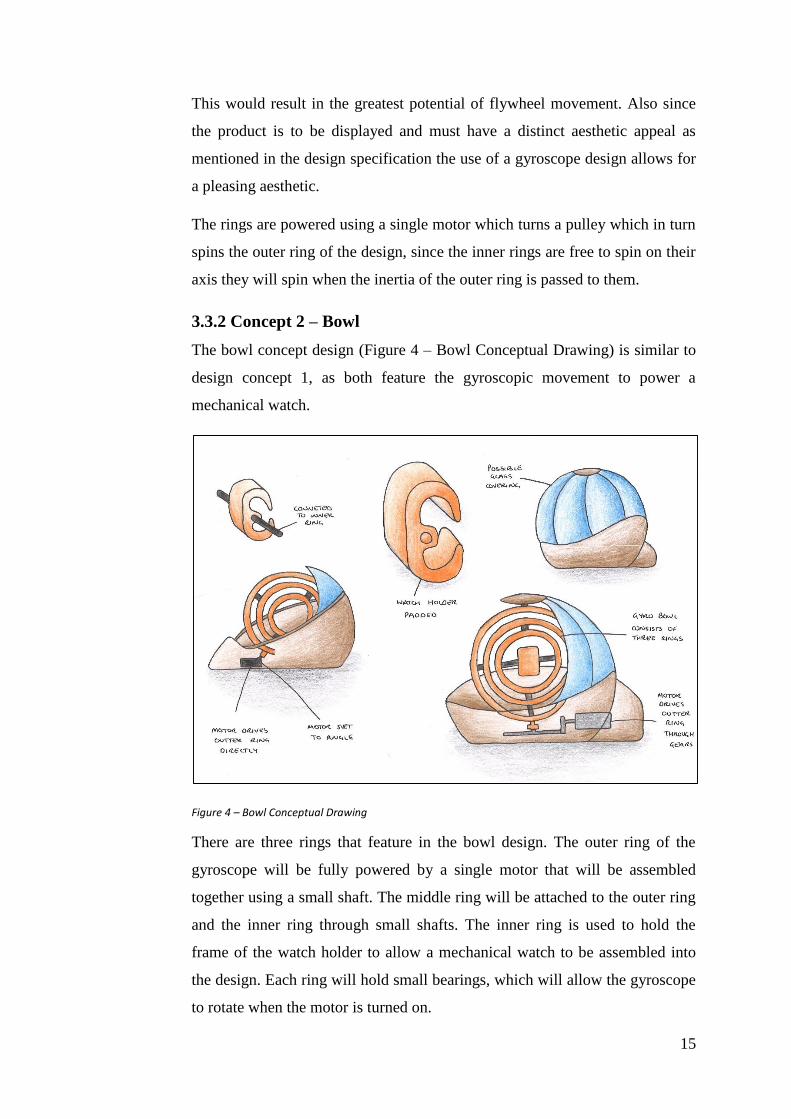
3.3.2 Concept 2 – Bowl
The bowl concept design (Figure 4 – Bowl Conceptual Drawing) is similar to
design concept 1, as both feature the gyroscopic movement to power a
mechanical watch.
Figure 4 – Bowl Conceptual Drawing
There are three rings that feature in the bowl design. The outer ring of the
gyroscope will be fully powered by a single motor that will be assembled
together using a small shaft. The middle ring will be attached to the outer ring
and the inner ring through small shafts. The inner ring is used to hold the
frame of the watch holder to allow a mechanical watch to be assembled into
the design. Each ring will hold small bearings, which will allow the gyroscope
to rotate when the motor is turned on.

16
The bowl design is not just functional in winding a watch, but it is also
aesthetically pleasing which would attract consumers. The possible glass
covering would not only look good sitting on a consumer’s desk, but it would
also add that safety feature in preventing any fingers or lose ends getting stuck
inside the gyroscope while it is turning.
3.3.3 Concept 3 – Gears
This design concept is focused on the watch winder acting as a discussion
piece. The concepts that are made apparent in Figure 5 – Gear Conceptual
Drawing. As with the rotating gears and having the automatic watch placed
within the large gear on to; the intent here was to produce design that would
resemble the watch for a high end display piece. This would incorporate
material finishes such as metal for the rotating gears and wood for the base.
Figure 5 – Gear Conceptual Drawing
There would also be a protective case placed onto of the watch winder so that
it is safe near children. The watch winder would be driven by a single gear
powered by a motor hidden within the base. All of these designs are focused
on one automatic watch being inserted into the watch winder. The large gear
would need to be wide enough for the watch to be easily removed without it
being damaged.
17
The watch would be placed onto a system that has a soft cushion type material
in the centre of the large gear that is slotted into position.
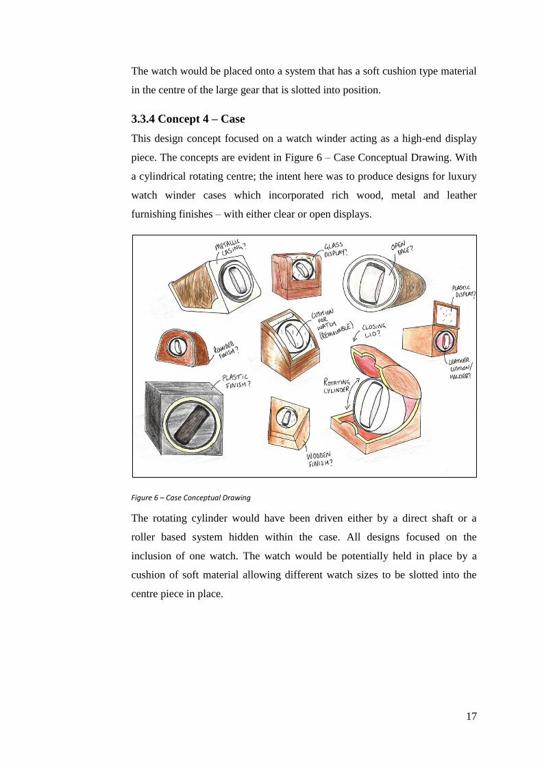
3.3.4 Concept 4 – Case
This design concept focused on a watch winder acting as a high-end display
piece. The concepts are evident in Figure 6 – Case Conceptual Drawing. With
a cylindrical rotating centre; the intent here was to produce designs for luxury
watch winder cases which incorporated rich wood, metal and leather
furnishing finishes – with either clear or open displays.
Figure 6 – Case Conceptual Drawing
The rotating cylinder would have been driven either by a direct shaft or a
roller based system hidden within the case. All designs focused on the
inclusion of one watch. The watch would be potentially held in place by a
cushion of soft material allowing different watch sizes to be slotted into the
centre piece in place.
18
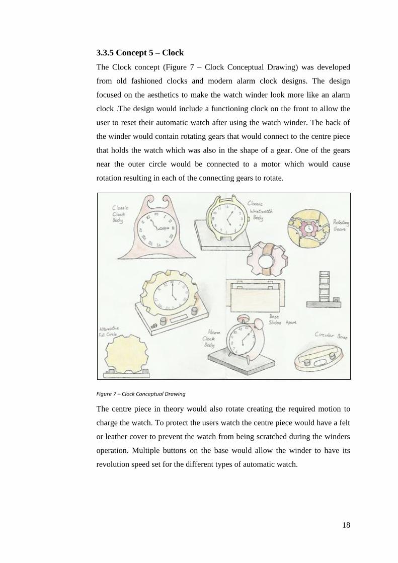
3.3.5 Concept 5 – Clock
The Clock concept (Figure 7 – Clock Conceptual Drawing) was developed
from old fashioned clocks and modern alarm clock designs. The design
focused on the aesthetics to make the watch winder look more like an alarm
clock .The design would include a functioning clock on the front to allow the
user to reset their automatic watch after using the watch winder. The back of
the winder would contain rotating gears that would connect to the centre piece
that holds the watch which was also in the shape of a gear. One of the gears
near the outer circle would be connected to a motor which would cause
rotation resulting in each of the connecting gears to rotate.
Figure 7 – Clock Conceptual Drawing
The centre piece in theory would also rotate creating the required motion to
charge the watch. To protect the users watch the centre piece would have a felt
or leather cover to prevent the watch from being scratched during the winders
operation. Multiple buttons on the base would allow the winder to have its
revolution speed set for the different types of automatic watch.

19
3.4 Convergence Matrix
The use of this technique is to evaluate the design concepts generated by each group
member to find the best solution that meets the customer needs before working on
detail design and development of the automatic watch winder.
The convergence matrix uses the inputs from the PDS with a number of generated
concept solutions to satisfy these needs of the customer. This was help to develop the
requirements and the solutions by showing where the needs had not been met. This
helps to develop the concept solutions further so that a final concept can be selected
and taken to the final stages of development.
A Datum was used for comparison for each feature of the concept solutions. This
common solution (DATUM) is also to be replaced final generated concept so using a
design that is that already exists is best used for this.
Table 2 – Convergence Matrix
The concepts are possible but not all suit the requirements needed by the customer.
The concepts generated by each individual member of the group where evaluated in a
neutral comparison that lead to a common understanding of why the gyro slab concept
solution was chosen as seen in Table 2 – Convergence Matrix.
Slab Bowl Gears Flip Clock
Function 5 5 4 4 4
Material Requirements 4 3 3 4 3
Size of Product 3 4 4 4 4
Storage 4 4 3 5 4
Cleaning
& Maintenance 4 3 3 4 3
Aesthetics 5 5 4 4 4
Quality 4 4 4 4 4
Safety 4 4 3 5 4
Cost 4 3 3 4 3
Manufacturing 4 4 3 4 3
Legal or Patents 4 4 4 4 4
Disposal 4 4 3 4 3
Competition &
Target Market4 4 3 4 4
Total 53 51 44 50 47
ConceptCriteria
20
3.5 Final Design Choice
From convergence matrix the Slab concept was chosen as seen Table 2 –
Convergence Matrix it scored high in all of the criteria set out in the PDS. The design
of this concept for the watch winder would use gyroscopic movement for the outer
rings and the automatic watch would be placed in the middle of these rings so that
with this type of rotational movement it would charge any automatic watch either
single directional or bi-directional. This design would use a motor powered belt
system that was to be hidden inside the watch winder.
The design of the Slab concept took safety into account as the only exposed moving
parts would be the gyro rings that follow the gimballed gyroscopic rotational
movement this proposed concept would need to be kept away from children when in it
would be in operation. This watch winder concept would be simple to manufacture as
it requires few components and would be easy to maintain for the end user.
The project supervisor Dr Robert Bailey had also chosen alternative design which was
the bowl concept this had also scored high in the convergence matrix. The design also
had outer rings that followed gyroscopic movement but would have a different way to
achieve this. This design would use a motor to create the movement of the gyro rings
so that the automatic watch would spin freely in a bi-directional movement.
The proposal of this concept was matched with the simplistic way it would achieve
the gimballed gyroscopic rotational movement to allow the automatic watch to charge
and the small amount of parts required so that it would bring a more simplistic feel to
the watch winder’s design. With having not many parts the watch winder design
would make it easy to manufacture and also maintain for the use end user.

21
4. Development
This chapter discusses different standards of watches, methods of moving the watches, and
the design and basic dimensions used in Creo to create prototype models.
4.1 Standards for Watch Sizes
One main factor that has to be discussed when designing a watch winder is the safety
and security of the mechanical watch within the watch winder device. The mechanical
watch must be as secure as possible to prevent the watch from leaving the frame,
damaging the watch or even damaging the watch winder itself. The understanding in
preventing this from happening is gaining knowledge of the standards of mechanical
watch sizes so that a design can created which is suitable for all different sizes of
watches.
When the two watch winder devices are turned on and the gyroscopic rings are
turning, the mechanical watch has to be secure within the watch winder. The watch
must not scrape off the inner gyroscopic ring due to the thickness or overall diameter
of the face on the watch and the watch must not slide off the holder.
The three main factors that will be discussed below that are relevant when talking
about standards for watch sizes are; the variations of front face dimensions, the
thickness of the watch and overall length of the watch. To start, we will have a look
at the different front face dimensions on a mechanical watch.
The first main factor to consider for the standards of watch sizes is the different
dimensions of the front face of the watch. The watch must spin safely within the
watch winder device and the front face should definitely not come in contact with the
inner ring of the gyroscope. From research, the faces of most mechanical watches
vary between 24millimeters to 48millimeters. From these dimensions we are able to
design the thickness of the watch holder and also make sure the inner ring is big
enough to prevent coming in contact with the watch. Figure 8 – Face Sizes below
shows the gradual increase of front face dimensions that could be expected.

22
Figure 8 – Face Sizes
Now that we have the possible dimensions of the front face of watches, we can have a
look at the variation in wrist sizes or the overall length of a mechanical watch. The
reason the length is a major factor is because the watch must be wrapped around the
holder while the gyroscopic rings turn the watch. Now if the watch being used has a
strap design, there are no real problems as a strap watch can simply be adjusted to fit
over the holder within the watch winder. The main problem would be the linked
watches that cannot be adjusted. If the holder within the watch winder is too small,
the watch will be able to fit around the holder however it would simply fall off
causing damage to the watch and to the rings on the gyroscope. If the holder is too
big, some watches may not be able to fit around the holder which would mean the
watch winder is unusable.
Figure 9 – Watch Length
The wrist size for most mechanical watches are broke down into small, medium, large
and extra-large sizes. Small being 7.6 – 11.4 centimetres, Medium 12.7 – 15.2
centimetres, Large 16.5 – 19.1 centimetres and X-Large 20.3 – 25.4 centimetres. A
design where the watch holder could be adjusted to suit all wrist sizes and lengths
would help solve this problem. Below is a diagram of what the overall length of a
watch is (Figure 9 – Watch Length).

23
We now have the standards of wrist sizes and front face dimensions for a mechanical
watch. The last factor to look at is the overall thickness of the watch. Just like the
front face of the watch, the thickness of the watch has to be taken into consideration
so that it does not scrape off the inner rings of the gyroscope.
When it comes to the thickness of a watch, we have thin, average and thick watches.
Thin being 6-8mm, Average 8-12mm and Thick 14-18mm. From these dimensions,
the watch holding frame must not have too large a diameter as once a thick watch has
been assembled onto it, the watch will simply come in contact with the inner ring. As
long as we can assemble the thickest watch onto the watch holding frame without
touching the inner ring of the gyroscope, we will have no problems. The diagram
below shows the dimension of the thickness of a watch (Figure 10 – Watch
Thickness).
Figure 10 – Watch Thickness
That completes the task of identifying the main standards for mechanical watches.
The front face dimensions, the overall length and the thickness of mechanical watches
have been discussed which will help with the design of the watch winder devices.
4.2 Methods of Movement
The movement of the automatic watch relates to the release of energy from the wound
spring rather than a battery to power the watch. The “spring stores the energy and
transfers it through a series of gears and springs allowing the release of energy to
power the watch” (Wixon Jewelers, 2015).
The movement of the two proposed watch winder concepts use a gimballed
gyroscopic movement which means that one axis has been placed in a fixed position.
“The gimballed gyroscopic movement only resists a tilting change in one axis. It will
not move with any given force” (Pearson, 2015).

24
A gyro that is gimballed in a plane that is vertical to the tilting force. As the outer
gyro ring rotates through the gimballed plane all the energy is then transferred to the
inner ring by the tilting force which is then mechanically stopped.
“The ring then rotates back into the tilting force plane where the speed will be
accelerated again” (Pearson, 2015). Every time the ring is accelerated the axis moves
in an arc in the tilting force plane. There is no change in the speed of the ring around
the axis. The gyro is a device that causes a smooth shift of motion from one plane to
another, “where the two planes intersect along the axis” (Pearson, 2015).
The slab concept uses a belt driven motor to start the movement of the outer ring
which in turn transfers the energy to the internal rings so that they will also begin to
rotate. The internal rings of this concept are also fixed at on a single axis but are free
to rotate back and forth which allows for bi-directional movement of the watch
winder.
The Bowl concept uses a motor to rotate the outer ring which in turn transfers the
energy to the internal rings so that they will also begin to rotate. The internal rings of
this concept are also fixed at on one axis but are free to rotate back and forth which
allows for the bi-directional movement to charge the automatic watch.
4.3 Design and Basic Dimensions
Provided that a requirement arose for two designs – one from the “customer” (the
groups dissertation supervisor) and the other being the team’s chosen concept – the
group was split – with each half of the team being assigned one of the intended
designs. This request would not be out of place in the manufacturing or design
industry, where a potential customer or client may request for more than one variation
of the same design. One half of the group was allocated the gyroscopic watch winder
with a base unit, and the other half was advised to begin work on a gyroscopic bowl
design.
Having assessed the standards of watch sizes and the methods of movement for the
watch winders; work began on constructing conceptual prototype designs of the watch
winders. These designs were constructed by employing key functions in Creo. Creo is
a suite of CAD (Computer Aided Design) software which supports product design for
discrete manufacturing – which is the production of distinct items such as cars,

25
furniture, smartphones, toys or airplanes (JD Edwards World Product Data
Management, 2015). Creo allows for 3D models of intended design concepts to be
virtually constructed and amended accordingly to suit user or client specification.
During the design & development of the watch winders, the group had to keep two
key factors in mind while creating the designs suitable for rapid prototyping:
1. The dimensional print space available on the 3D printer
2. The restrictions & availability of parts (ordered from selected university
component suppliers) envisioned to be used in the design
These are areas which are discussed in their own respective segments.
The first area focused on was the centre piece of the gyroscopic rings which holds the
watch. Based on the average watch strap size of between 170 – 180 mm, the teams
aimed to keep their watch holder at a similar circumference to replicate the size of the
average wrist. Ideally; an adjustable watch cradle would be preferable, however, both
teams felt that for the purposes of a prototype an average would suffice.
Figure 11 – Watch Holder Models
Both watch holders could then potentially wrapped in a material such as neoprene to
allow for watches larger than this circumference to remain in place without slippage.
The team working on the base design focused on a spring clip mechanism which locks
the watch holder in place to an inner gyroscopic ring; whereas the bowl design team
opted for a snap-fit clip design into an inner ring. The spring clip watch cradle also
features holes for weight inserts to calibrate the weight distribution of the centre piece
26
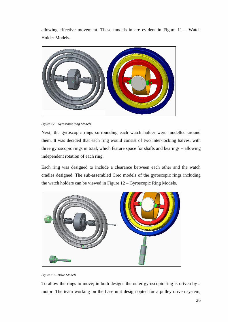
allowing effective movement. These models in are evident in Figure 11 – Watch
Holder Models.
Figure 12 – Gyroscopic Ring Models
Next; the gyroscopic rings surrounding each watch holder were modelled around
them. It was decided that each ring would consist of two inter-locking halves, with
three gyroscopic rings in total, which feature space for shafts and bearings – allowing
independent rotation of each ring.
Each ring was designed to include a clearance between each other and the watch
cradles designed. The sub-assembled Creo models of the gyroscopic rings including
the watch holders can be viewed in Figure 12 – Gyroscopic Ring Models.
Figure 13 – Drive Models
To allow the rings to move; in both designs the outer gyroscopic ring is driven by a
motor. The team working on the base unit design opted for a pulley driven system,

27
whereas the designers working on the bowl iteration chose a directly driven shaft
design.
The pulley system in the base design and the direct shaft of the bowl concept can be
seen in Figure 13 – Drive Models. The dimensions used for these systems were
referenced from the manufacturers sizing guides and drawings.
Figure 14 – In Progress Modelling
Lastly, the base and bowl of each respective watch winder was created. This was
achieved by creating new parts in Creos assembly mode whilst the ring sub-
assemblies were inactive but present.
This allowed the groups to reference the sizes of the pre-created ring & cradle
assemblies to create new parts – all whilst not interfering with existing geometry.
Given limitations with the 3D printers print area, both base and bowl designs had to
be split into segments which, once rapid prototyped, would be assembled together. In
progress CAD models at this stage are highlighted in Figure 14 – In Progress
Modelling.

28
Figure 15 – Fully Assembled Models
Figure 15 – Fully Assembled Models displays the fully assembled intended designs in
Creo. Figure 27 – Base Drawing to Figure 31 – Full Assembly Drawing in the
Appendix 1 – Drawings show general dimensional drawings for each design and their
main components created.
5. Designs
This chapter discusses the process of ordering the required components for both watch
winder concepts and provides realistic clay models of the final intended watch winder
designs.
5.1 Parts Lists
A Bill of Materials is a necessity for a number of reasons in for the manufacturing
process of a product. It allows the manufacturer to calculate the overall cost of the
product before the manufacturing process begins. This allows alterations in materials
or parts to be judged at an early enough stage that it will not cause problems.
The quantity of requested parts can be checked to prevent anything from being
forgotten. Appropriate dimensions can be analysed to prevent parts being ordered
which will not fit the final design.
Slab Watch Winder Parts list – Table 3 – Parts List (Slab).
Bowl Watch Winder Parts list – Table 4 – Parts List (Bowl).

29
Table 3 – Parts List (Slab)
Part Description Material Quantity Dimensions (mm) Supplier Value (£)
1 AC Motor Steel 1 65.9 x 41.65 x RS 32.36
2 Pulley Stainless Steel 2O Dia. 20 x
Bore 8 x Width 12HPC Gears 8.66
3 Belt Polyurethane 1 200 x Dia 3 HPC Gears 2.52
4 Bearing Steel 12 11.5 x 4 x Bore 3 RS 1.15
5Transformer
(12V)Plastic 1 2.1 Jack Amazon 4.99
6 Relay Plastic, Fibre 1 50 x 17 x 19 EBay 1.99
7 Arduino Uno Plastic, Fibre 1 80 x 56 x 20 Amazon 22.19
8 Pins Plain Steel Bag of 25 12 x Dia 3 RS 4.21
9 ScrewsNickel
Plated BrassBag of 100 16 x Dia 2 RS 4.89
10 WiresCopper
ConductorBag of 10 75 Long Maplin 4.59
11Switch
(250V AC)Plastic 1
6.8 x 19 x
4.8 Faston TerminalsMaplin 0.99
12 ButtonBrass, Silver
plated terminals 1 18 x 18 Maplin 3.19
13Blue LED
ScreensPlastic, Acrylic 1 40 x 23 x 8.5
Cool
Components10.79
14 Plug Plastic 1 2000 Lead Amazon 1.9
15 Springs Steel Alloy Bag of 10 23.5 x 3.7 RS 0.65
Overall
Price£105.07
30
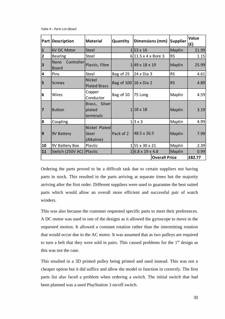
Table 4 – Parts List (Bowl)
Ordering the parts proved to be a difficult task due to certain suppliers not having
parts in stock. This resulted in the parts arriving at separate times but the majority
arriving after the first order. Different suppliers were used to guarantee the best suited
parts which would allow an overall more efficient and successful pair of watch
winders.
This was also because the customer requested specific parts to meet their preferences.
A DC motor was used in one of the designs as it allowed the gyroscope to move in the
requested motion. It allowed a constant rotation rather than the intermitting rotation
that would occur due to the AC motor. It was assumed that as two pulleys are required
to turn a belt that they were sold in pairs. This caused problems for the 1st design as
this was not the case.
This resulted in a 3D printed pulley being printed and used instead. This was not a
cheaper option but it did suffice and allow the model to function in correctly. The first
parts list also faced a problem when ordering a switch. The initial switch that had
been planned was a used PlayStation 3 on/off switch.
Part Description Material Quantity SupplierValue
(£)
1 6V DC Motor Steel 1 Maplin 21.99
2 Bearing Steel 6 RS 1.15
3Nano Controller
BoardPlastic, Fibre 1 Maplin 25.99
4 Pins Steel Bag of 25 RS 4.61
5 ScrewsNickel
Plated BrassBag of 100 RS 4.89
6 Wires Copper
ConductorBag of 10 Maplin 4.59
7 Button
Brass, Silver
plated
terminals
1 Maplin 3.19
8 Coupling 1 Maplin 4.99
9 9V Battery
Nickel Plated
Steel
(Alkaline)
Pack of 2 Maplin 7.99
10 9V Battery Box Plastic 1 Maplin 2.39
11 Switch (250V AC) Plastic 1 Maplin 0.99
£82.77
48.5 x 26.5
55 x 30 x 21
6.8 x 19 x 4.8
Overall Price
49 x 18 x 19
24 x Dia 3
16 x Dia 2
75 Long
18 x 18
3 x 3
Dimensions (mm)
53 x 16
11.5 x 4 x Bore 3

31
The part could not be ordered which resulted in a second 250V switch having to be
ordered. Fortunately the 250V switch would suffice and did not cause any problems in
the manufacturing stage. Certain parts were used in both designs.
This allowed certain parts which could only be delivered in large quantities to be used
on both designs without resulting in a large amount of left-over parts. By selecting
smaller screws, the outer casing of the watch winder would still be connected securely
while allowing the screws to be less visible to any customer resulting in a more
desirable product. For both of the watch winder designs, a large amount of parts were
made from Nylon by Rapid Prototyping. The body, base and rings of each of the
designs were Rapid Prototyped as well as the bearings for one of the designs. This
allowed the creation of the exact shape and size desired for each of the models.
“More organic, sculptured shapes for functional or aesthetic reasons can be
accommodated” (Chee Kai Chua, 2010, p. 15)
The benefits of rapid prototyping were that the creation of the parts through the CAD
software Creo ProEngineer allowed an easy designing process for each of the required
parts with simple and quick access to alteration if necessary. In comparison to
machining parts, the CAD system had fewer constraints to be set up resulting in a
considerably simpler process. The finished parts had a smooth surface as well as
being strong. Unless the part was put under a large amount of pressure the part would
not break. As the 3D printed material is brittle the parts being used would not bend
under stress. This was perfect for the watch winder model as the product is stationary
while functioning and would not suffer over a long period of time.

32
5.2 3DS Max Renders
3DS MAX has been used to render the two watch winder designs. This can be seen in
Figure 16 – Dual Clay Render below. Other clay renders are evident in Appendix 3 –
3DS Max Renders.
Figure 16 – Dual Clay Render
The final renders of each of the design can be seen in the Appendix 3 – 3DS Max
Renders, these renders were created to present a fully finished image of the final
designs to the client. The renders show the final design with the application of
multiple materials and colours used to create the body of the winder design.
33
6. Prototyping
This chapter discusses the process of developing watch winder prototypes using rapid
prototyping, the assembling of the prototypes, programming involved, and explanation of the
coding used.
6.1 3D Printing
3D Printing is also known as Additive Layered manufacturing where a digital 3D
model is designed on a Computer Aided Design (CAD) program and is then saved
into a STL file where it is then stored in the 3D printing machine. Once the machine
has understood the data received from the STL file, the exact 3D design is
constructed.
The process planning for 3D printing can be set-up quickly, however, once the STL
file has been saved into the machine the time it takes to print the 3D model can take
some time depending on the size of the component and also the layer thickness
selected. For example, the larger the layer thickness, the less time it takes the machine
to produce the component. The majority of the components created for the two watch
winding designs will be 3D printed as this will allow us to create any complex shapes
designed from the CAD program.
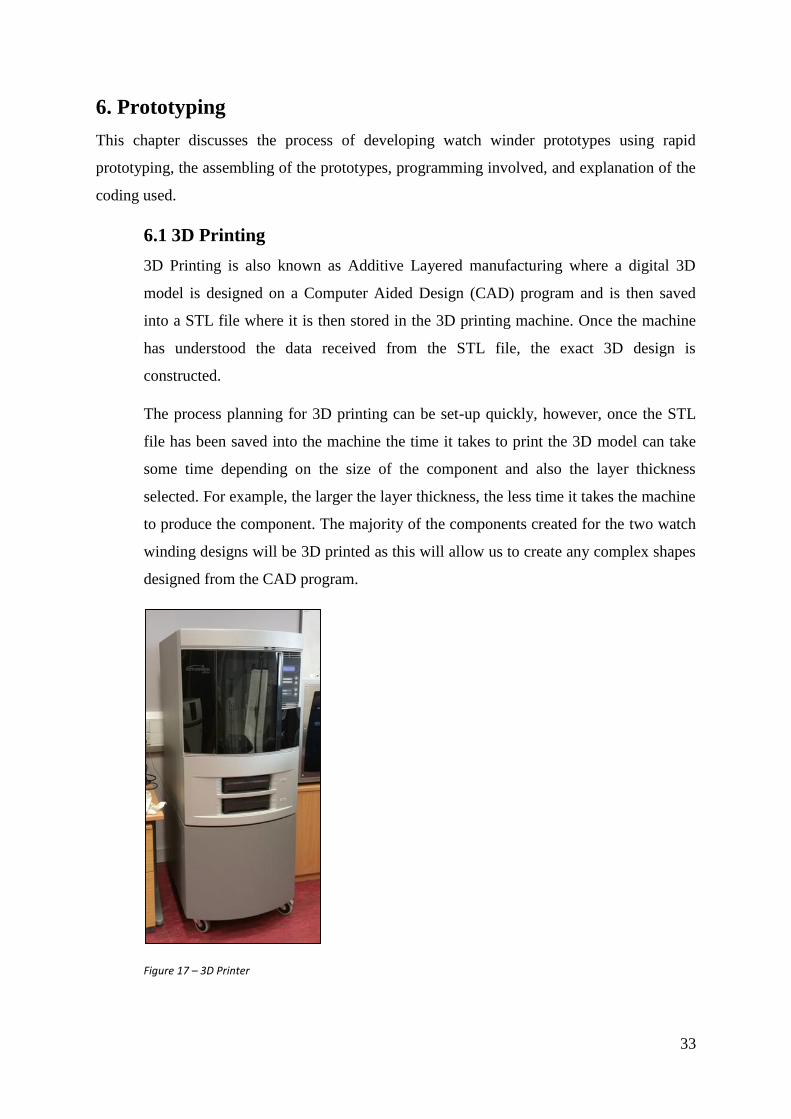
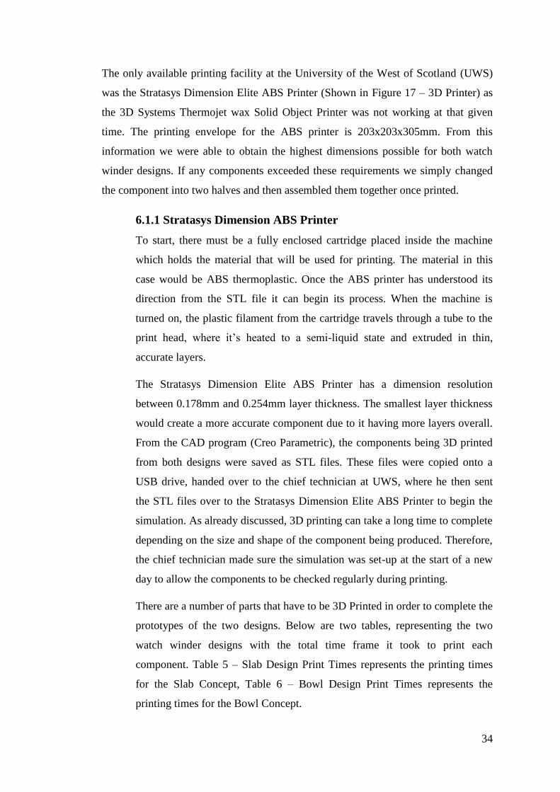
Figure 17 – 3D Printer
34
The only available printing facility at the University of the West of Scotland (UWS)
was the Stratasys Dimension Elite ABS Printer (Shown in Figure 17 – 3D Printer) as
the 3D Systems Thermojet wax Solid Object Printer was not working at that given
time. The printing envelope for the ABS printer is 203x203x305mm. From this
information we were able to obtain the highest dimensions possible for both watch
winder designs. If any components exceeded these requirements we simply changed
the component into two halves and then assembled them together once printed.
6.1.1 Stratasys Dimension ABS Printer
To start, there must be a fully enclosed cartridge placed inside the machine
which holds the material that will be used for printing. The material in this
case would be ABS thermoplastic. Once the ABS printer has understood its
direction from the STL file it can begin its process. When the machine is
turned on, the plastic filament from the cartridge travels through a tube to the
print head, where it’s heated to a semi-liquid state and extruded in thin,
accurate layers.
The Stratasys Dimension Elite ABS Printer has a dimension resolution
between 0.178mm and 0.254mm layer thickness. The smallest layer thickness
would create a more accurate component due to it having more layers overall.
From the CAD program (Creo Parametric), the components being 3D printed
from both designs were saved as STL files. These files were copied onto a
USB drive, handed over to the chief technician at UWS, where he then sent
the STL files over to the Stratasys Dimension Elite ABS Printer to begin the
simulation. As already discussed, 3D printing can take a long time to complete
depending on the size and shape of the component being produced. Therefore,
the chief technician made sure the simulation was set-up at the start of a new
day to allow the components to be checked regularly during printing.
There are a number of parts that have to be 3D Printed in order to complete the
prototypes of the two designs. Below are two tables, representing the two
watch winder designs with the total time frame it took to print each
component. Table 5 – Slab Design Print Times represents the printing times
for the Slab Concept, Table 6 – Bowl Design Print Times represents the
printing times for the Bowl Concept.

35
Table 5 – Slab Design Print Times
Table 6 – Bowl Design Print Times
From the above tables, the overall times to print the Slab Design and the Bowl
Design were 78.5 Hours and 49 Hours. From this, we understand that the
Bowl design is more efficient in saving material, cutting costs and more
importantly saving time. Not all components were included in the two tables,
however the final printing times are accurate. It must also be said that in
Design Concept 1, the front and base components were printed into four
sections due to the size of the overall component. The base was also split into
two sections. The overall sizes of these components exceeded the size of the
printing envelope within the ABS printer and had to be sectioned. For the
rings, two sides each were printed off to allow the assembly of bearings. The
overall printing times for these components are produced in Table 5 – Slab
Design Print Times.
Components Printed Time to Print
Outer Ring 5.8 Hours
Middle Ring 3.1 Hours
Inner Ring 2.6 Hours
Front 24.4 Hours
Back 25.6 Hours
Base 13.2 Hours
Watch Cradle 2.5 Hours
Total Time 78.5 Hours
Design Concept 1 – Slab Design (Mark & Ross)
Components Printed Time to Print
Outer Ring 4.5 Hours
Middle Ring 3.75 Hours
Inner Ring 3.25 Hours
Watch Holder 2.5 Hours
Attachment 2 Hours
Cover 0.5 Hours
Bowl/Base 32 Hours
Total Time 49 Hours
Design Concept 2 – Bowl Design (Thomas & William)

36
From Table 6 – Bowl Design Print Times, Design Concept 2, the rings were
again printed off as two sides to allow bearings to be fitted. The overall time in
which it took to print off the two sides has been provided. Also for the
Bowl/Base component, it states that it took 32 hours to print. This section was
divided into two parts due to the size of the part exceeding the building
envelope requirements. One side took 16 Hours, and both are symmetrical.
When the 3D printing simulation had finished, all components had not yet
been completed as there were still final alterations to be made. Most of the
time when the 3D printing machine creates complex components there are
support structures that are automatically created to help produce that
component.
The support structure is thinner than the actual component being made and can
be simply removed by brushing away the excess material or by dipping the
component into a special liquid. Once this has been done, the geometry of the
actual component is complete. This was done for all the components for both
watch winder designs.
6.2 Assembly of the Watch Winders
The way in which the watch winders would be assembled was designed during the
conceptual and final design ideas. Different parts proved to be more problematic than
others, all of which were simply altered to allow the assembly to run correctly and just
as competent. The assembly was created in parts which were brought together
separately. Both of the winders were assembled in very similar ways.
The initial connection was the three gyroscopic rings. Each ring was printed in two
separate halves and were connected through 4 holes and shafts. These holes and shafts
were designed on each ring purely for assembling purposes. Two bearings were added
to each of the rings. By linking each of the three rings with steel pins, the bearings
were able to rotate creating inertia from the outer ring to the inner ring allowing fast
rotation. The rings were controlled by motors.

37
Figure 18 – Soldering
The Gyro Slab design was controlled by an AC motor while the Gyro Bowl design
was controlled by a DC motor. The motors were controlled by Arduino controller
boards. A code was created allowing the motors to run and rotate the rings for 60
seconds before stopping for 5 seconds. The code was created using the downloaded
Arduino software on a laptop. Wires connected the Arduino boards to the motors
which were soldered together using a soldering iron as seen in Figure 18 – Soldering.
The rings were connected to the watch winder’s shelled bodies. Each of the two
bodies were glued together allowing a strong connection. The Gyro Slab winder had
four parts constructing the front panel and four parts constructing the back panel.
Each of the four parts were glued together using Araldite adhesive creating the front
and back parts of the body.
The front and back panel were not glued together so that the back panel could be
removed to allow access to the inside of the prototype. A base attachment acted as a
seat to allow the two panels to sit in. The Gyro Bowl winder was printed in two halves
which were glued together. These two halves were then glued to a front attachment
which created space for the motor and controller board to be placed. The final part of
the body assembly was a lid which sat on top of the attachment. This was to hide the
inside components and to create a complete body. The lid had a cut on the bottom
right edge to allow it to be removed giving the user access to the inside components.
With the completion of the winder bodies, the rings were connected to the available
slots on the bodies. The rings were connected to bearings, which were held in the
body, using steel rods.

38
This allowed the rotation despite being securely fastened to the body. The Gyro Bowl
design had its outer ring connected to the body vertically at 0° and 180° allowing the
motor to control the ring rotation from the bottom. The Gyro Slab winder had
horizontal connections at 90° and 270°.
The different positions did not result in either winder having a greater rotation or
differed function. Both winders had identical performances. The Gyro Bowl design
had its DC motor running straight into the bottom of the outer ring creating the
rotation necessary for the centre piece and watch. The Gyro Slab design, however,
had its motor connecting to a crank shaft which would rotate when the motor was on.
A Polyurethane belt was then connected to the crank shaft and a Pulley which would
rotate due the connecting belt. The Pulley was attached to the pin that came from the
outer ring’s bearing which ultimately rotated the rings due to the simple assembly
process from the motor. Both winders had a centre piece that allowed the watch to sit
on. Both centre pieces were different for each winder. The Gyro Bowl design’s centre
piece consisted of three different parts. The parts were an oval ring, a flat rounded
disk and rectangular bar, which was where steel pins were connected. The disk acted
as a flat surface so that the watch could sit level during the rotation preventing
slippage which could scratch or damage the watch. The oval ring was designed so that
a watch’s strap could be fastened around it. Steel screws connected the three parts
together.
The steel pins on the rectangular bar where assembled to the inner ring. No bearings
were used in this connection as the centre piece was not to move. The ring in which it
was connected to would allow enough of a rotation to allow the watch to wind up.
The Gyro Slab’s centre piece however was very much a different design. A rounded
solid oval shape was created which would connect to two components that attached to
the inner ring. The two components acted as the connectors between the centre piece
and the rings.
Each of the two components were printed in halves which would snap together to
create the one hollow component. Within each component were two prong like pins.
These pins were created for the steel alloy springs to fit into as well as sliding into to
available holes in the oval centre piece.

39
The springs allowed the centre piece to be connected and disconnected from the inner
ring with ease as the two components could be squeezed together releasing the centre
piece from its position in the centre of the rings.
The inner ring had two areas available for the components to sit on the inside of its
circumference on opposite sides from one another. This allowed the springs within the
components to extend creating an outward force on the inner rings wall but within the
spaces available so that the centre piece would not slip during the rotation.
The components within the Gyro Slab design were attached to the front panel to allow
the prototype to stand vertically without the components moving around inside. The
Transformer, Relay and Arduino Uno were screwed onto the front panel in the slots
which were designed for this assembly process. The screws allowed a secure
fastening preventing any slippage or movement from the components. As there were a
number of wires connecting the internal components, Blu-Tack secured the wires in a
safe and suitable position where they would not become tangled.
The AC motor was a large and heavy component which could not simply be glued to
the body panels due to its weight and the vibrations that occur while it is running.
Therefore, a platform was created to allow the motor to remain in a suitable position
while the crank shaft rotated.
The platform design ensured that the motor would not move position during its
operation. It was a simple box shape which was assembled to the front panel with
Araldite adhesive. The motor sat comfortably in the box allowing the rotation of the
crank shaft and ultimately the rings.
With the full assembly and connection of each component in the Gyro Slab design,
both the back and front panel could be brought together finishing the assembly of the
winder. The front and back panel connection allowed the rings to sit comfortably
within the winder.
During the design of the panels, the connection process was taken into account. Slots
were created so that screws could be placed between each of the front and back panel.
Once the screws were securely fastened into the available slots the design was
complete.

40
6.3 Programming
The prototypes are controlled using an Arduino UNO for the gyro Slab and an
Arduino Micro for the GyroBowl. Arduino boards use a variant of the 'C'
programming language. Arduino
The three stages of an Arduino program are as follows:
The initial section is used to declare any and all variables and to allocate pin
designations. Pins is the short hand term used to describe the input/output interface
pins that the Arduino uses to send and receive signals. The variables are declared to
allow the required space in the Arduino memory for whatever information the
variable will contain.
There are several types of variable that can be used such as String, Integer. An Integer
is number, a standard integer variable is allocated 2 bytes of the Arduino memory for
storage. Allowing for storage of numbers in the range of -32,768 to 32,768.
The second stage of an Arduino program is called ‘Setup’. The setup up function is
called when a sketch starts, it is used to initialize variable
The third and final stage of the Arduino program is the loop section. The loop
function does exactly what its name would suggest. It consecutively loops, allowing a
program to run, change and respond.
The approach taken in programming both the gyro bowl and the GyroSlab was the
same, power the motor, then cut power to the motor and wait for an allotted period of
time.
Due to the looping nature of the Arduino there was no need to create a looping
procedure the program will loop itself continuously as long as power is supplied to the
Arduino. As addressed in the ‘Design Specification’ the timing for the winders will be
1 minute of activation time for every hour of run time.
The interval time between activation of the motor was taken from the brief and was
stated to be 60 minutes wait with an active run time of 1 minute. To achieve these
time intervals the 'delay' command was used.
The delay command allows the program to be paused for a specified length of time
without interrupting the signal from the Output pin.
41
A delay was applied to allow both the minute run time and the hour long interval
between activations, in order to have the program wait for the appropriate length of
time the required wait time must be entered into the delay as milliseconds. Therefore
for the hour wait the length of time required can be expressed as:
delay(3600000));
Above it can be seen that 1 second can be expressed as 1000 milliseconds, therefore
1000*60 will result in a time of 1 minute, and this is used in the active run time code.
The by multiplying this again by 60 give the total time for in milliseconds for an hour.
1 minute = 60 x 1000 = 60,000 milliseconds
1 hour = 60x 60 x 1000 = 3,600,000 milliseconds.
6.3.1. Gyro Bowl and Slab Coding
Since the gyro bowl makes use of a low voltage DC motor and is powered via
a single 9v battery the Arduino board can be programmed to control the output
voltage directly. Simply put the 9V battery will be used to power the Arduino
and the Arduino will then in turn power the motor. However the motor used in
the GyroSlab design was a 230V AC motor. Since there would not be
sufficient power to the Arduino can only OUTPUT a max volts t
It is noteworthy to mention the code shown below was uploade3d to the
GyroBowl prototype, however with exception to the pin used to control the
motor for the GyroBowl and the pin used to close the relay for the GyroSlab
the coding is identical therefore an explanation of both code is not warranted.
unsigned long wait_time;
unsigned long run_time;
unsigned long time;
int motor_pin = 5;pinMode(Motor_Pin, OUTPUT);
The code above begins with establishing the variables as ‘long’ data types.
This data type is different than a standard integer variable as it uses 4 bytes
instead of the standard 2 bytes, this allows for a range from -2,147,483,648 to
2,147,483,648. Also here the pin that is attached to the motor is established,
this informs the Arduino that this pin will be referred to as 'Motor_Pin from
now on. Following from this the Arduino begins the 'void_setup' function.

42
void setup()
{
// sets up the motor pin.
pinMode(motor_pin, OUTPUT);
run_time = (60000); // 1 min activation time.
wait_time = (3600000); // 60 min wait time.
Serial.begin(9600);
}
Here 'pinMode' is entered, this is a function of the Arduino program that
allows the setup of the pin itself, here the Arduino is told what pin will be used
and then the function of the pin. Since the 'Motor_Pin' is sending out a voltage
to power the motor it is set to OUTPUT. Following this the ‘run_time’ and the
‘wait_time’ .The last section is the loop. Any code within the loop will draw
on the variables and setting written in the setup or prior, and then perform the
functions stated within the loop.
void loop()
{
// testing Code, Print time to monitor
Serial.print("Motor on: ");
time = millis();
Serial.println(time);
// Run Code - Turns motor on.
digitalWrite(motor_pin, HIGH);
delay(run_time);
// testing Code. prints time to Monitor
Serial.print("Motor off: ");
time = millis();
Serial.println(time);
// Run Code - Turns motor off.
digitalWrite(motor_pin, LOW);
delay(wait_time);
Here the main body of the program resides. It begins with the serial print
function. This is a built in function of the Arduino board that allows the
monitoring of the outputs of the board. This was used in the context of testing
the program to ensure that the timing of the program meets with the required
activation times. This relies on the internal timer of the Arduino board, this is
known as the millis() function.

43
The millis function is an internal timer that records the time since the Arduino
board has been activated (since it was powered). The millis() function is not
directly viewable therefore the program has been set to allow the ‘time’
variable to be equal to the millis function.
This means when the program reaches this line the values stored in the millis()
variable at that moment is entered in to the time variable. The following line
writes the time in the serial output. The main body of the program will then
begin.
Then the program moves to the next section of code which contains the motor
activation signal. Following this the program is instructed to wait for the
required time set by the run_time variable the standard value of 60,000
milliseconds results in the wait of a single minute. This means the motor will
activate for a single minute. After the delay the program resumes, the serial
print command is given again and the time is recorded in the time variable and
printed to the serial monitor.
The program the moves into the final section of the code, again this is a simple
command that tells the Arduino board to change the power setting of the
motor or relay pin to LOW or off. This will disrupt the power supply to the
motor causing deactivation of the motor.
The line following this tells the board how long this command will last. The
same logic as the run_time variable the Wait_time variable is entered here and
since the value for this is 3,600,000 millisecond this results in a wait time of 1
hour.
Flowing this there is no other code to instruct the board to perform any
additional functions so the loop restarts following the wait delay. Once the
loop restarts the entire section of program contained within the loop function
is ran again, the nature of the Arduino board means that the program will
continue to run the program until the boards power supply has been
interrupted.
44
6.4 Testing
Before the program was uploaded to the prototypes the Arduino boards had to be
programmed. The program was first tested using the built in LED light on the
Arduino Uno board as this would indicate that the program written was running. The
program that was used to conduct this was used to test the timing setup of the boards.
The simple LED program that was written was to turn the built in LED on an off at set
timed intervals. The initial program was set to turn on for 5 seconds and off for
another five seconds. This was also observed externally by an observer who was using
a stop watch. This was to ensure that the timing methods that were used in the
program were accurate and matched with real time frames.
Once the low interval times were deemed to be working effectively the times were
increased to determine longer interval times which would have an effect on the
Arduino board's accuracy.
Once the final program was uploaded onto the Arduino board within the prototypes a
command was included that would print the time when the motor would activate and
deactivate to a monitor output from the Arduino board to the pc which was used to
write and upload the program.
Before the final test which was to upload the program into the final assembly the
electronics were tested using a multi-meter which is a piece of equipment that
“measures electric current, voltage and usually resistance” (wiseGEEK, 2015). The
electronic components were signed off by an experienced electronics creator.
The final test was to have the serial monitor running at the same time when the
prototype was fully assembled and running. For this test another observer with a stop
watch was present to measure the time and the serial monitor was running to note the
outputs from the Arduino board.
The result from testing the program had the slab design running for 10 spins which
was 10 hours without any problems. The bowl design had run for 2 spins which was
2-3 hours until the battery could no longer sustain power to the motor even though the
Arduino was still active.

45
7. Discussion and Reflection
During the assembly of the prototype, a number of issues occurred. These issues were a result
of a number of factors; incorrect dimensions, the material not being strong enough for small
parts and programming software complications. By considering the reason for the issue, all of
these problems were resolved using an alternative method.
One reoccurring issue was dimensional problems. Incorrect dimensions occurred in the
assembly where buttons or pins were to be inserted into holes. The tolerances were not
considered, holes were not dimensioned for the exact size of pins or button’s and also the
ABS 3D printer used isn’t 100% accurate due to the layer thickness produced.
Due to the prototypes material being an ABS thermoplastic, the layered structure is strong
and brittle allowing the holes for buttons to be easily filed. The holes on the rings were drilled
out to 3millimeters to allow room for the pins. This introduced the help from the technicians
at UWS as they were able to set the rings up in a 3 axis milling machine, and drilling out the
holes using a 3millimeter drill bit.
For both the slab winder and bowl winder, the bearings that were used inside the rings which
created the gyroscopic motion, were too loose in their designated seat. The bearings not
having a tight connection defeated their functional purpose as the whole body would rotate
rather than the inside ring. To prevent this from happening, blue-tac was placed between the
bearings seat and the bearing itself. This prevented the whole body of the bearing from
moving and only allowing the inner ring’s rotation which was connected to pins.
Dimensional problems were not only an issue when it came to incorrect sizes. Small
dimensions caused problems when it came to strength. Although the ABS was a strong
material, if the dimensions were small, the plastic could snap depending on the purpose of
certain parts. To allow the watch holder to be connected to the inner ring in the bowl concept,
two shafts were created. These shafts would snap fit into a connecting hole. Due to their
small diameter, the shafts snapped when attempting to remove them (see Figure 19 - Failure).

46
Figure 19 - Failure
Rather than redesigning this centre piece and the shafts, holes were drilled where the shafts
had been situated. Again this was done by using the 3 axis milling machine and a 3millimeter
drill bit.
A steel rod was then cut to size and assembled into these new holes. The steel rod would
allow the same snap fit assembly but had the strength that the ABS did not have preventing
the new shafts from snapping when being assembled and removed.
Once the outer shell of the bowl winder was adequate for the Nano controller board and
motor to be added to the assembly, it was noticed that the motor’s shaft would rub against
available hole for the connection between the shaft and the outer ring. Again, this hole was
filed to size. The Nano controller board caused multiple issues which were ongoing
throughout the assembly. The code was created through a laptop and was initially accepted
by the controller board allowing the gyroscopic motion.
When it was connected to a new laptop, the controller board damaged this laptop to the point
that it would not turn on. The reason behind this was not known. When attempting to alter the
code on the laptop initially used, the controller board would not always accept the code. It
would struggle to find which port it was connected to in the laptop which was solved by
disconnecting the controller board and reconnecting it to another port.
It was assumed that as two pulleys are required to turn a belt that they were sold in pairs. This
caused problems for the Gyro Slab design as this was not the case. A 3D Rapid Prototyped
pulley was printed and used instead.

47
This was not a cheaper option but it did suffice and allow the model to function in correctly.
The pulley was designed with a connecting rod attached to it which then connected to the
motor acting as a crank shaft which benefitted the design.
The AC motor was a large and heavy component which vibrated while it was operating.
Therefore it could not simply be glued to the body panels. To tackle this situation a platform
was designed to allow the motor to be mounted. To guarantee that the best suited platform
was used two different designs were created and printed allowing each design to be tested.
The first design was a simple box which would allow the motor to sit comfortably while
operating. The position in which the box was designed to sit would allow the motor to
operate the crank shaft while the watch winder was standing vertically upright.
The second design was a solid box shape with a curved top. It was designed to fit into the
base attachment while the motor sat on top in a suitable for it to function correctly. The
second design was not suitable when tested as it was too large to fit in the base attachment.
This meant that the motor was not in a suitable position for the motor to operate correctly.
Therefore the first design was used.
The assembly of the front and back panel in the Gyro Slab design had one minor issue. The
slots for the screws were too large. This resulted in larger screws being purchased to
guarantee a secure connection between the front and back panel. Until the screws were
purchased the connection could not be made completing the Gyro Slab winder.
During the connection of the front and back panels it was noticed that the cable from the
Arduino controller board to the mains was too large for the hole that was created in the base.
To prevent this issue the bottom of the front panel was filed creating a suitable sized hole for
the cable to pass through.
Despite a large order of components for the initial winder designs, not all of the parts were
used in the final prototypes. Due to the size of the prototype the Blue LED screen was not
used. It would be too small for the prototype and was not necessary for the winders main
function.
The button was not used on the Gyro Slab design as only the switch was required to turn the
winder on and off. As the winder was powered by a switch connected to the mains, only one
switch or button was necessary to turn the winder on or off.
48
Initially a Nano Control Shield was purchased and planned for the operation of the winder.
Due to the change in design and the way in which the winder would operate the Transformer
replaced the Nano Control Shield to allow for a better operation. The screws and pins that
were purchased were only available in packets of large amounts.
As the winders only used the required amount the assembly there was a lot left over which
were not used. Unfortunately this was not able to be avoided as this was the way in which
these components were sold by the suppliers.

49
8. Conclusion
Through planned research, careful time management, critical feedback, utilisation of CAD
software, and the employment of additive and subtractive processes; the team logically
applied the knowledge gained during their time at UWS, as well as a host of personal skill
sets to satisfy the requirements the project outlined.
Despite an initial requirement to construct a working watch-winder for the purpose of
maintaining power in automatic watches; the group worked together to successfully create
two working, fully functional, gyroscopic watch winder prototypes.
The watch winders created have the prospective to be manufactured for sale and, given more
time and resources; this could be an idea which could potentially be realised.

50
9. Recommendations for Future Work
Having met the task and created the two prototypes for the watch winder design there are a
number of aspects that could be improved with more time.
The use of Arduino boards is not a long term inclusion in the design, ideally the use of
custom designed control boards would be a better means of programmed control for the
watch winders. These boards could be designed and fabricated in house as the AT Mega chip
that the Arduino board utilizes is commercially available and rather inexpensive and could be
bought in.
Refinement of the designs to allow a range of the winder products if the line is taken into
mass manufacture would be another area for investigation. The GyroSlab design could be
altered slightly to allow for the inclusion of a second set of gyroscopic rings and watch
cradle. This would mean that the winder would be capable of holding two watches at one
time. Again this could be further evolved to allow the GyroSlab design to be capable of
holding and increased number of watches at a single time.
Due to the requirement of having to buy in the components from approved vendors, in order
to construct the prototypes of both the GyroSlab and the GyroBowl. Due to this restriction the
dimensions of several of the components did not fit with the initial designs. Changes
therefore had to be made to allow the use of these components this had a resulting effect on
the scale of the designs. An example of ne such component was the pulley used in the
GyroSlab prototype, the pulley available from the supplier was larger than the initial design
allowed for. Therefore changes had to be made to allow the use of the pulley in order to
transfer rotation from the motor to the rings.
The inclusion of a larger range fof vendors would allow for a greater probability of finding
component parts that would match the initial design, furthermore the used of custom created
parts that match the design components exactly would allow for full preservation of the initial
design.
At current the programming of both the watch winders is simplistic; as soon as power is
supplied to the program will activate and is fixed as to the length of time it can run for. An
improvement would be to allow for the user to alter the length of time the program will allow
the rings to spin for and also the length of time the program will remain inactive before the
rings are activated again.

51
9.1 Possible Manufacture
As prototypes are created to prove the concept of a given design; the groups were not
focused of perfecting a finalised design, but a representation of a product which could
then potentially be manufactured for a target market.
The majority of products in today’s modern society involve plastics to some extent;
from the clothes people wear to the cars that they drive. These commodities are
typically mass produced on a grand scale, some of which are created using injection
moulding techniques by manufacturing companies. Molten plastic is injected at high
pressure into a mould core & cavity, which contains a hollow space representing the
part shape. In order for companies to use injection moulds, the moulds themselves
have to be firstly designed; this job typically would be assigned to a product designer.
CAM (Computer Aided Manufacturing) software, such as Creo, can allow design and
manufacturing companies to assess potential products for manufacturing. If the parts
of the watch winders were to be produced in plastic and moulds were required for
production, Creo could analyse factors such as, but not limited to:
Drafts check – the determination of areas within a reference model which do
not satisfy minimum draft angles
Thickness check – the analysis of the thickness throughout a reference model
to satisfy minimum material or mould requirements
Undercut check – the determination of areas where mould sliders may be
required to achieve undercuts
Gate Location – the examination of the best location to inject molten plastic
Much similar to the creation of the watch winder parts; moulds could then be created
on Creo to produce 3D models of mould core & cavities for each part.
Next, using the newly created mould models; the user could then recreate a
manufacturing environment – again by utilising key functions in CAM software such
as Creo. Creo would allow the user to replicate the working space used to create
moulds. With a vast catalogue of tools, VMCs (Vertical Machining Centres), and
techniques available; the user would be able to simulate the production of the moulds
by configuring NC (Numerical Controlled) tool paths.

52
These tool paths could then be analysed to ensure the products being produced are
done with:
Minimum cost
Minimum time resource
Reduced material waste
Minimum machine time
…all whilst maintaining a quality end product. The aforementioned steps avoid the
use of any raw materials, tools or labour as there are virtual simulations. This is
advantageous as there comes low risk due to the low cost associated with CAM
simulations.
3D rapid prototypes of the moulds could also be constructed; allowing product
designers to identify design flaws or usability issues and make the appropriate
changes quickly.
The rapid prototyping process provides an accurate model which can then be used to
create production tooling, decreasing the risk of issues in the manufacturing phases.
The moulds produced from the reference model (watch winder) could then be used to
manufacture the plastic components required.
53
Bibliography
Bibliography
Chee Kai Chua, K. F. L. C. S. L., 2010. Rapid Prototyping: Principles and Applications. 3rd ed.
Singapore: World Scienfific Publishing Co. Pte. Ltd..
Dictionary.com, 2015. Morphology. [Online]
Available at: http://dictionary.reference.com/browse/morphology
Edwards, S., 2010. Watch Movement Buying Guide | Overstock. [Online]
Available at: http://www.overstock.com/guides/watch-movement-buying-guide
[Accessed 12 March 2015].
Jason Heaton, 2013. Five Best Watch Winders - Gear Patrol. [Online]
Available at: http://gearpatrol.com/2013/03/08/wound-up-five-best-watch-winders/
[Accessed 1 April 2015].
JD Edwards World Product Data Management, 2015. JD Edwards World Product Data
Management - Discrete Guide. [Online]
Available at: docs.oracle.com/cd/E26228_01/doc.93/e21777.pdf
Pearson, C. (., 2015. Gyroscopes - Everything you need to know. [Online]
Available at: http://www.gyroscopes.org.uk/how.asp
[Accessed 13 March 2015].
Pearson, C. (., 2015. Gyroscopes - Everything you need to know. [Online]
Available at: http://www.gyroscopes.org.uk/how.asp
[Accessed 15 March 2015].
Raspberry Pi Foundation, 2012. UPCOMING BOARD REVISION. [Online]
Available at: http://www.raspberrypi.org/upcoming-board-revision/
Rolex, 2015. Rolex Watchmaking: Materials. [Online]
Available at: http://www.rolex.com/about-rolex/materials.html
[Accessed 13 March 2015].

54
Slater, R., 2015. GRIPS. [Online]
Available at: http://www.coach-and-courses.com/grips.pdf
Timp, 2013. DIY watch winder. [Online]
Available at: https://www.youtube.com/watch?v=FLTEH6_23oc
[Accessed 21 April 2015].
Treffinger, D. J., 2000. Creative Problem Solver's Guidebook. In: s.l.:Prufrock Press Inc., p. 40.
wiseGEEK, 2015. What Is a Multimeter?. [Online]
Available at: http://www.wisegeek.org/what-is-a-multimeter.htm#comments
[Accessed 20 March 2015].
Wixon Jewelers, 2015. Watch Movements | Differences Between Mechanical & Quartz.
[Online]
Available at: http://www.wixonjewelers.com/education/swiss-watches/watch-movements/
[Accessed 14 March 2015].
Ziglar, D., 2005. Chronocentric. [Online]
Available at: http://www.chronocentric.com/watches/winders.shtml
[Accessed 2 April 2015].

55
Appendix 1 – Drawings
Bowl Design
Figure 20 – Bowl Attachment Drawing
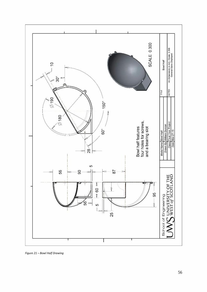
56
Figure 21 – Bowl Half Drawing
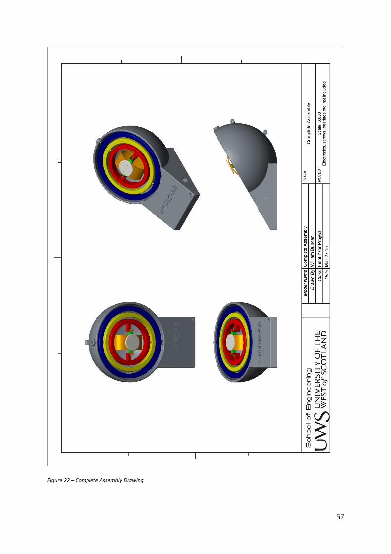
57
Figure 22 – Complete Assembly Drawing

58
Figure 23 – Cover Drawing

59
Figure 24 – Ring Assembly Drawing

60
Figure 25 – Motor Vice Drawing

61
Slab Design
Figure 26 – Back Panel Drawing

62
Figure 27 – Base Drawing

63
Figure 28 – Shaft Drawing
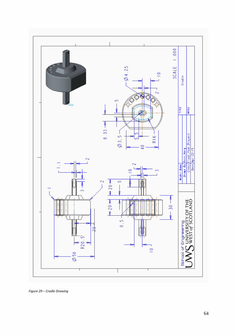
64
Figure 29 – Cradle Drawing

65
Figure 30 – Front Panel Drawing
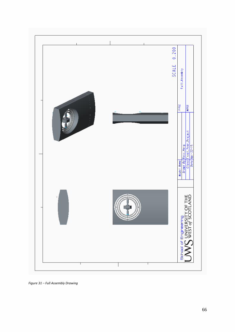
66
Figure 31 – Full Assembly Drawing
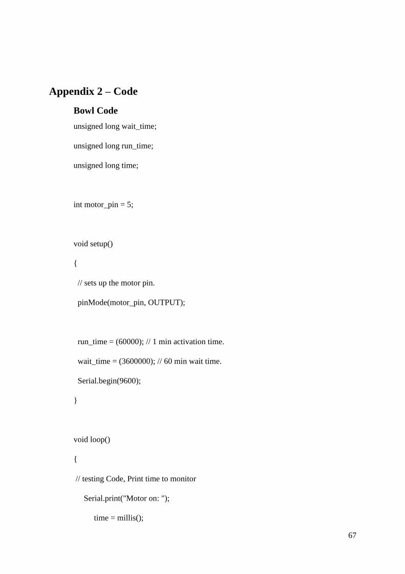
67
Appendix 2 – Code
Bowl Code
unsigned long wait_time;
unsigned long run_time;
unsigned long time;
int motor_pin = 5;
void setup()
{
// sets up the motor pin.
pinMode(motor_pin, OUTPUT);
run_time = (60000); // 1 min activation time.
wait_time = (3600000); // 60 min wait time.
Serial.begin(9600);
}
void loop()
{
// testing Code, Print time to monitor
Serial.print("Motor on: ");
time = millis();
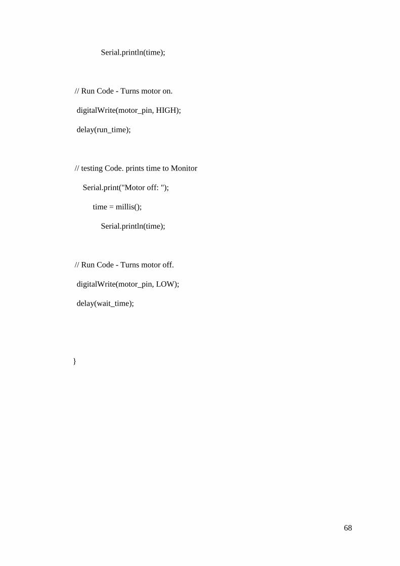
68
Serial.println(time);
// Run Code - Turns motor on.
digitalWrite(motor_pin, HIGH);
delay(run_time);
// testing Code. prints time to Monitor
Serial.print("Motor off: ");
time = millis();
Serial.println(time);
// Run Code - Turns motor off.
digitalWrite(motor_pin, LOW);
delay(wait_time);
}

69
Slab Code
unsigned long wait_time;
unsigned long run_time;
unsigned long time;
int Led_Pin = 13;
void setup()
{
// establishes the motor pin and designates it as output only
pinMode(motor_pin, OUTPUT);
// State the time in milliseconds (1000th of a second)
run_time = (60000);
wait_time = (3600000);
// Output to Arduino monitor - TESTING ONLY
Serial.begin(9600);
}
void loop()
{
Serial.print("led on: ");
time = millis();
Serial.println(time);

70
digitalWrite(motor_pin, LOW);
delay(run_time);
Serial.print("led off: ");
time = millis();
Serial.println(time);
digitalWrite(Led_Pin, HIGH);
digitalWrite(motor_pin, HIGH);
delay(wait_time);
}

71
Appendix 3 – 3DS Max Renders
Clay Renders
Figure 32 – Slab Clay Render
Figure 33 – Bowl Clay Render
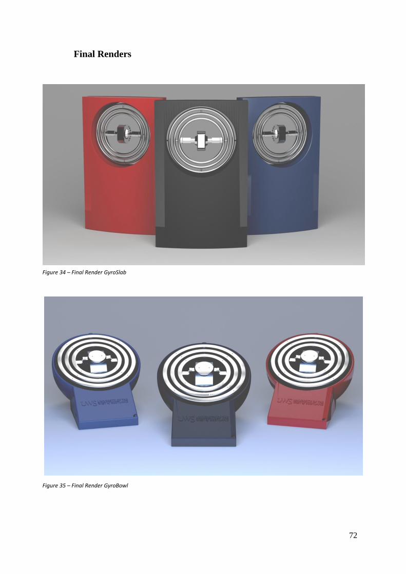
72
Final Renders
Figure 35 – Final Render GyroBowl
Figure 34 – Final Render GyroSlab

73
Appendix 4 – Miscellaneous
Figure 36 – GRIPS Meeting Sheet
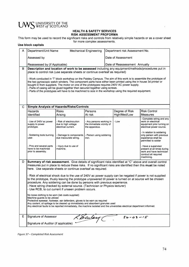
74
Figure 37 – Completed Risk Assessment