[et-t, ah11 an analog electronic cochlea
TRANSCRIPT

[Et-t, IKANSACTIONS ON ,KOUSTICS. SPEECH. Ah11 SIGNAL PKOCESSING. \ O L 36. N O 7. Jul.” 19x8 1119
An Analog Electronic Cochlea RICHARD F . LYON, M E M B E R , IEF-F. A N D CARVER MEAD
Absfracf-An engineered system that hears, such as a speech recog- nizer, can be designed by modeling the cochlea, or inner ear, and higher levels of the auditory nervous system. To he useful in such a system, a model of the cochlea should incorporate a variety of known effects, such as an asymmetric low-passibandpass response at each output channel, a short ringing time, and active adaptation to a wide range of input signal levels. An analog electronic cochlea has been built in CXIOS VLSI technology using micropower techniques to achieie this goal of usefulness via realism. The key point of the model and circuit is that a cascade of simple, near13 linear, second-order filter stages with con- trollable Q parameters suffices to capture the physics of the fluid-d>- namic traveling-wave sjstem in the cochlea. including the effects of adaptation and active gain involving the outer hair cells. hleasure- ments on the test chip suggest that the circuit matches hoth the theory and observations from real cochleas.
I . INTRODUCTION HEN we understand how hearing works. we will be able to build amazing machines with brain-like abil-
ities to interpret the world through sounds (i .e. , to heur). As part of our endeavor to decipher the auditory nervous system, we can use models that incorporate current ideas of how that system works to engineer simple systems that hear in simple ways. The relative success of these systems then helps us to evaluate our knowledge about hearing. and helps to motivate further research.
As a first step in building machine:; that hear, we have implemented an analog electronic cochlea that incorpo- rates much of the current state of knowledge about coch- lear structure and function. The biological cochlea is a complex three-dimensional fluid-dynamic system, illus- trated schematically in Fig. 1 . In the process of design- ing, building, and testing the electronic cochlea, we have had to put together a coherent view of the function of the biological cochlea from the diverse ideas in the literature. This view and the resulting design are the subject of this paper.
The approach used to model the nonuniform fluid-dy- namic wave medium of the cochlea as a cascade of filters is based on the observation that the properties of the me- dium change only slowly and that wave energy is there- fore not reflected to any significant degree [ 11. The effect of active outer hair cells is included as a variable negative
Manuscript received Fehruaq 22. 1988. This work was supported by the Sq stem Development Foundation and by Schlumberger Palo Alto Re- search.
R . F. Lyon is with Apple Computer Inc.. Cupertino. CA 95014. and the Department of Computer Science. California Institute of Technology, Pasadena. CA 91 125.
C . Mead is with the Department of Computer Sciencs. California Insti- tute of Technolog . Pasadena. CA Y I115
IEEE Log Number 8821363.
Obal Window
Round W,ndow
/-----.
‘ v ’ F l u , d Paths , ,’ --__/-
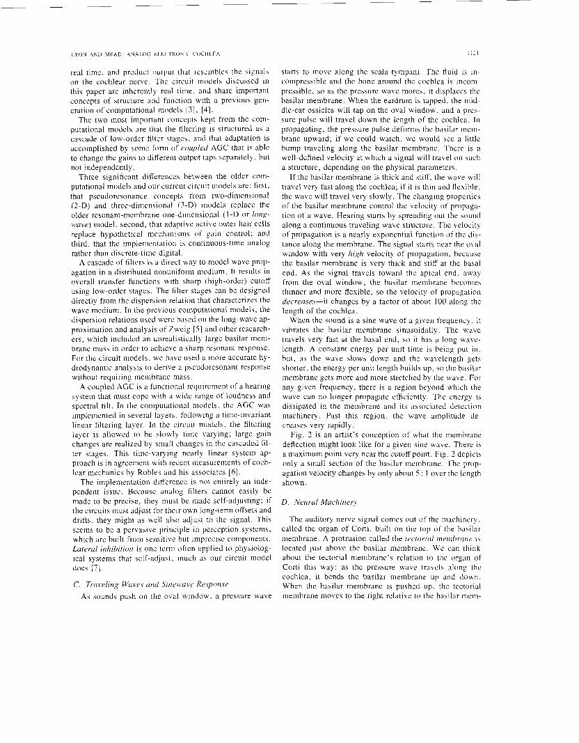
Fig. I , Anist‘s conception of the cochlea. with cutaway showing a cross xction of a cochlear duct. The bending of the cochlear partition causes a shcarinp between it and the tectorial membrane, which can be both sensed and amplified by hair cells in the organ of Corti. The dashed lines indicate fluid paths from the input at the oval v.indow and back to the round window for pressure relief.
damping term; the variable damping mechanism is shown to be effective as a wide-range automatic gain control (AGC) associated with a moderate change in sharpness of tuning with signal level. The cascade structure enforces unidirectionality, so a coarse discretization in space does not introduce reflections that could otherwise cause insta- bility in an active model. The system is not highly tuned, but rather achieves a high-gain pseudoresonunce by com- bining the modest gains of many stages; nevertheless, sharp iso-output tuning curves result from the interaction of the adaptive gains and the filters, as has been observed experimentally in both neural frequency threshold curves and basilar membrane iso-velocity curves.
The cascade filter model is implemented using contin- uous-time analog CMOS (complementary metal-oxide- semiconductor) VLSI (very large scale integrated) cir- cuits. The building block of the filters is a transconduc- tance amplifier operated in a subthreshold micropower re- gime, in which the long time constants needed for audio processing can be controlled easily without the use of clock signals. Variable-Q second-order filter stages in cascade are adequate to capture most of the important qualitative effects of real cochleas.
11. WAVES A N D THE INNER EAR The inner ear, or cochlea, is the interface between sound
waves and neural signals. In this section we review sev- eral points of view on the purpose, structure, function, and modeling of this complex organ.
A . Background oti Hearing We hear through the sound analyzing action of the
cochlea (inner ear) and the auditory centers of the brain.
0096-351818810700-1119$01 .OO O 1988 IEEE

1120 IEEE TRANSACTIONS ON ACOUSTICS, SPEECH, AND SIGNAL PROCESSING, VOL. 36, NO. 7, JULY 1988
As with vision, hearing provides a representation of events and objects in the world that are relevant to survival. Just as the natural environment of light rays is cluttered, so is that of sound waves. Hearing systems therefore have evolved to exploit many cues to separate out complex sounds. The same systems that have evolved to help cats catch mice and to warn rabbits of wolves also serve to let human speak with human. Except for the highest level of the brain (the auditory cortex), the hearing systems of these animals are essentially identical.
The mechanical-neural transducer of the hearing sys- tem is the hair cell, which evolved from the flow-sensing lateral line organ of fishes and also is used in the inertial equilibrium system of the inner ear. This cell detects the bending motion of its hairs (actually cilia) and responds by a change in internal voltage and a release of neuro- transmitter. The function of the cochlea is to house these transducers and to perform a first level of separation, so that each transducer processes a differently filtered ver- sion of the sound entering the ear. The outer and middle ears gather sound energy and couple it efficiently into the cochlea.
A less obvious but equally important function of the outer, middle, and inner ears is to adapt to a wide range of sound intensities by suppressing loud sounds and by amplifying soft ones. The outer ears are involved by con- scious pointing. The middle ear is involved through a pro- tective reflex that contracts the stapedius muscle (and, in some species, the tensor tympani muscle) to reduce the transfer efficiency after detecting a loud sound. The inner ear’s involvement is most amazing; it uses hair cells to couple energy back into the acoustic system to amplify weak sounds. Adaptation to signal level continues to be important through higher levels of the nervous system.
Setting aside neural processing for now, let us consider the sound analysis done in the cochlea. Roughly, the cochlea consists of a coiled fluid-filled tube (see Fig. 1) with a stiff cochlear partition (the basilar membrane and associated structures) separating the tube lengthwise into two chambers (called ducts or scalae). At one end of the tube, called the basal end, or simply the base, there is a pair of flexible membranes called windows that connect the cochlea acoustically to the middle-ear cavity. A trio of small bones or middle ear ossicles couple sound from the eardrum (tympanic membrane) into one of the win- dows, called the oval window. When the oval window is pushed in by a sound wave, the fluid in the cochlea moves, the partition between the ducts distorts, and the fluid bulges back out through the round window (the elastic round window acts to complete the circuit, allowing fluid to move). The hair cells sit along the edge of the partition in a structure known as the organ of Corti, and are ar- ranged to couple with the partition motion and the fluid flow that goes with it.
The distortion of the cochlear partition by sounds takes the form of a traveling wave, starting at the base and propagating toward the far end of the cochlear ducts, known as the apical end, or apex. As the wave propa-
gates, a filtering action occurs in which high frequencies are strongly attenuated; the cutoff frequency gradually lowers with distance from base to apex. The inner hair cells, of which there are several thousand, detect the fluid velocity of the wave as it passes. At low sound levels, some frequencies are amplified as they propagate, due to the energy added by the outer hair cells, of which there are about three times as many as inner hair cells. As the sound level changes, the effective gain provided by the outer hair cells is adjusted to keep the mechanical re- sponse within a more limited range of amplitude.
The propagation of sound energy as hydrodynamic waves in the fluid and partition system is essentially a distributed low-pass filter. The membrane velocity de- tected at each hair cell is essentially a bandpass-filtered version of the original sound. Analyzing and modeling the function of these low-pass and bandpass mechanisms is the key to understanding the first level of hearing.
A classical view of hearing, known as the place theory, is that the cochlea is a spectrum analyzer, and that its output level as a function of place (location in the cochlea measured along the dimension from base to apex) is a good characterization of a sound. This view leads to several ways of characterizing the cochlea, such as plots of best frequency versus place, neural firing rate versus place for complex tones, or threshold versus frequency for a given place, that tend to obscure the fact that the cochlea is really a time-domain analyzer. Even the analysis used in this paper, in terms of sinusoidal waves of various frequen- cies, might give the impression that the cochlea analyzes sounds based on their “frequencies.” In fact, the reason sinusoids are used is simply that they are the eigenfunc- tions of continuous-time linear systems, so the ugly-look- ing partial-differential-equation formulations of such sys- tems reduce to algebraic equations involving the parameters of the sinusoids.
The mathematical fact that arbitrary finite-energy sig- nals can be represented as infinite sums or integrals of sinusoids should not be construed, as it was by Ohm and Helmholtz [2], to mean that the ear analyzes sounds into sums of sinusoids. The great hearing researcher Georg von BCkCsy is said to have remarked, “Dehydrated cats and the application of Fourier analysis to hearing problems become more and more a handicap for research in hear- ing. ” Animal preparations have improved greatly since then, but there are still too many hearing researchers stuck on the Fourier frequency domain view. The main symp- tom of this fixation is the widespread interpretation of sharp iso-output tuning curves as implying sharp tuning in the sense of highly resonant or highly frequency-selec- tive filters. Our adaptive nonlinear system view provides a much simpler and more consistent interpretation in terms of unsharp tuning in combination with an AGC.
B. Cochlear Model Background The cochlea has been modeled by many researchers,
from a wide variety of viewpoints. For our purposes, a good model is one that can take real sound as input, in
LYON A N D MF.AD AKALOG ELECTRONIC COCHLEA 11'1
real time, and product nutput that resembles the bignalb on the cochlear nerve. The circuit models discussed in this paper are inherently real time. and share important concepts of structure and function with a previous gen- eration of computational models [ 31, [4].
The two most important concepts kept from the com- putational models are that the filtering is structured as a cascade of low-order filter stages, and that adaptation is accomplished by some form of coupled AGC that is able to change the gains to different output taps separately, but not independently.
Three significant differences between the older com- putational models and our current circuit tnodels are: first, that pseudoresonance concepts from two-dimensional (2-D) and three-dimensional (3-D) models replace the older resonant-membrane one-dimensional (1 -D or long- wave) model; second, that adaptive active outer hair cells replace hypothetical mechanisms of gain control; and third, that the implementation is continuous-time analog rather than discrete-time digital.
A cascade of filters is a direct way to model wave prop- agation in a distributed nonuniform medium. It results in overall transfer functions with sharp (high-order) cutoff using low-order stages. The filter stages can be designed directly from the dispersion relation that characterizes the wave medium. In the previous computational models, the dispersion relations used were based on the long-wave ap- proximation and analysis of Zweig [ 5 ) and other research- ers, which included an unrealistically large basilar meni- brane mass in order to achieve a sharp resonant response. For the circuit models, we have used a more accurate hy- drodynamic analysis to derive a pseudoresonant response without requiring membrane mass.
A coupled AGC is a functional requirement of a hearing system that must cope with a wide range of loudness and spectral tilt. In the computational models, the AGC was implemented in several layers, following a time-invariant linear filtering layer. In the circuit models, the filtering layer is allowed to be slowly time varying; large gain changes are realized by small changes in the cascaded fil- ter stages. This time-varying nearly linear system ap- proach is in agreement with recent measurements of coch- lear mechanics by Robles and his associates [ 6 ] .
The implementation difl'erence is not entirely an inde- pendent issue. Because analog filters cannot easily be made to be precise, they must be made self-adjusting; if the circuits must adjust for their own long-term offsets and drifts, they might as well also adjust to the signal. This seems to be a pervasive principle in perception systems, which are built from sensitive but imprecise components. Lateral inhibition is one term often applied to physiolog- ical systems that self-adjust, much as our circuit model does (71.
C. TrciL3eling Waves and S i i ~ m a v t J Resppor~sr As sounds push on the oval window, a pressure wave
starts to move along the scala tympani. The fluid is in- compressible and the bone around the cochlea is incon- pressible, so as the pressure wave mores, it displaces the basilar membrane. When the eardrum is tapped. the niid- dle-ear ossicles will tap on the oval window, and a pres- sure pulse will travel down the length of the cochlea. In propagating, the pressure pulse deforms the basilar mem- brane upward; if we could watch, we would see a little bump traveling along the basilar membrane. There is a well-defined velocity at which a signal will travel on such a structure, depending on the physical parameters.
If the basilar membrane is thick and stiff, the wave will travel very fast along the cochlea; if it is thin and flexible, the wave will travel very slowly. The changing properties of the basilar membrane control the velocity of propaga- tion of a wave. Hearing starts by spreading out the sound along a continuous traveling wave structure. The velocity of propagation is a nearly exponential function of the dis- tance along the membrane. The signal starts near the oval window with very high velocity of propagation, because the basilar membrane is very thick and stiff at the basal end. As the signal travels toward the apical end. away from the oval window, the basilar membrane becomes thinner and more flexible, so the velocity of propagation decreases-it changes by a factor of about 100 along the length of the cochlea.
When the sound is a sine wave of a given frequency, it vibrates the basilar membrane sinusoidally. The wave travels very fast at the basal end, so it has a long wave- length. A constant energy per unit time is being put in . but. as the wave slows down and the wavelength gets shorter, the energy per unit length builds up, so the basilar membrane gets more and more stretched by the wave. For any given frequency, there is a region beyond which the wave can no longer propagate efficiently. The energy is dissipated in the membrane and its associated detection machinery. Past this region, the wave amplitude de- creases very rapidly.
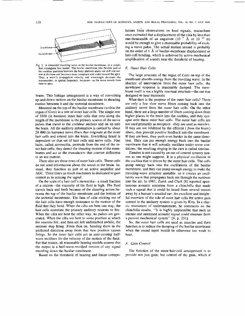
Fig. 2 is an artist's conception of what the membrane deflection might look like for a given sine wave. There is a maximum point very near the cutoff point. Fig. 2 depicts only a small section of the basilar membrane. The prop- agation velocity changes by only about 5 : 1 over the length shown.
D. Neurul Machinery
The auditory nerve signal comes out of the machinery. called the organ of Corti, built on the top of the basilar membrane. A protrusion called the tectoriul rnernbrurie ib located just above the basilar membrane. We can think about the tectorial membrane's relation to the organ of Corti this way: as the pressure wave travels along the cochlea, it bends the basilar membrane up and down. When the basilar membrane is pushed up, the tectorial membrane moves to the right relative to the basilar mem-
1122 IEEE TRANSACTIONS ON ACOUSTICS, SPEECH, AND SIGNAL PROCESSING, VOL. 36. NO. 7. JULY 1988
Oval Window
Round Window
Fig. 2. A sinusoidal traveling wave on the basilar membrane, in a simpli- fied rectangular box model. The basilar membrane (the flexible part of the cochlear partition between the bony shelves) starts out stiff and nar- row at the base and becomes more compliant and wider toward the apex. Thus, a wave’s propagation velocity and wavelength decrease-the wavenumber, or spatial frequency, increases-as the wave travels from base to apex.
brane. This linkage arrangement is a way of converting up-and-down motion on the basilar membrane to shearing motion between it and the tectorial membrane.
Mounted on the top of the basilar membrane (within the organ of Corti) is a row of inner hair cells. The single row of 3500 (in humans) inner hair cells that runs along the length of the membrane is the primary source of the nerve pulses that travel to the cochlear nucleus and on up into the brain. All the auditory information is carried by about 28 000 (in humans) nerve fibers that originate at the inner hair cells and extend into the brain. Everything heard is dependent on that set of hair cells and nerve cells. Fine hairs, called stereocilia, protrude from the end of the in- ner hair cells; they detect the shearing motion of the mem- branes and act as the transducers that convert deflection to an ion current.
There also are three rows of outer hair cells. These cells do not send information about the sound to the brain. In- stead, they function as part of an active amplifier and AGC. Three times as much machinery is dedicated to gain control as to sensing the signal.
On the scale of a hair cell’s stereocilia-a small fraction of a micron-the viscosity of the fluid is high. The fluid travels back and forth because of the shearing action be- tween the top of the basilar membrane and the bottom of the tectorial membrane. The fans of cilia sticking out of the hair cells have enough resistance to the motion of the fluid that they bend. When the cilia are bent one way, the hair cells stimulate the primary auditory neurons to fire. When the cilia are bent the other way, no pulses are gen- erated. When the cilia are bent to some position at which the neurons fire, and then are left undisturbed awhile, the neurons stop firing. From then on, bending them in the preferred direction away from that new position causes firings. So the inner hair cells act as auto-zeroing half- wave rectifiers for the velocity of the motion of the fluid. For that reason, all reasonable hearing models assume that the output is a half-wave-rectified version of any signal traveling down the basilar membrane.
Based on the threshold of hearing and linear extrapo-
lations frdm observations on loud signals, researchers once estimated that a displacement of the cilia by less than one-thousandth of an angstrom A or m) would be enough to give a reasonable probability of evok- ing a nerve pulse.oThe actual motion sensed is probably on the order of 1 A of basilar-membrane displacement or hair-cell bending, which is achieved by active mechanical amplification of sounds near the threshold of hearing.
E. Outer Hair Cells
The large structure of the organ of Corti on top of the membrane absorbs energy from the traveling wave. In the absence of intervention from the outer hair cells, the membrane response is reasonably damped. The mem- brane itself is not a highly resonant structure-the ear was designed to hear transients.
What then is the purpose of the outer hair cells? There are only a few slow nerve fibers coming back into the auditory nerve from the outer hair cells. On the other hand, there are a large number of fibers coming down from higher places in the brain into the cochlea, and they syn- apse onto these outer hair cells. The outer hair cells are not used primarily as receptors-they are used as muscles. If they are not inhibited by the efferent ( f rom the brain) fibers, they provide positive feedback into the membrane. If they are bent, they push even harder in the same direc- tion. They can put enough energy back into the basilar membrane that it will actually oscillate under some con- ditions; the resulting ringing in the ears is called tinnitus.
Tinnitus is not caused by an out-of-control sensory neu- ron as one might suppose. It is a physical oscillation in the cochlea that is driven by the outer hair cells. The cells pump energy back into the oscillations of the basilar membrane, and they can pump enough energy to make the traveling-wave structure unstable, so it creates an oscil- latory wave that propagates back out through the eardrum into the air. In 1981, Zurek and Clark [8] reported spon- taneous acoustic emission from a chinchilla that made such a squeal that it could be heard from several meters away by a human’s unaided ear. An excellent and insight- ful overview of the role of outer hair cells for active gain control in the auditory system is given by Kim. In a clas- sic monument of understatement, he comments on the chinchilla results, “It is highly implausible that such an intense and sustained acoustic signal could emanate from a passive mechanical system” [9, p. 25 11 .
So, the outer hair cells are used as muscles and their function is to reduce the damping of the basilar membrane when the sound input would be otherwise too weak to hear.
F. Gain Control
The function of the outer-hair-cell arrangement is to provide not just gain, but control of the gain, which it

LY!)N A N D M k A D ANALOG E L E C T R O N I C C O C H L E A I123
l o o ,
90 C, 1 "/sec Velocity
-
4 50-. 1 9 nm Displacement ' - 2 e 4 0 ~ -
-- -
30
20 --
1000 10000 l 0 J
100 Frequency (Hz)
Fig. 3. Mechanical and neural iso-output tuning c u n e s . based on data from Robles and his associates 161. The mechanical measurements (amount of inpiit needed to get 1 m m / s hasilar menihrane displacement velocity o r I!, .4 basilar mcmbrdne displacement amplitude) were made by measur- ing Doppler-shifted garnma rays (hliissbnuer ef tect) from a s i i i a l l radio- active source mounted on the cochlear partition. The iicurnl tuning curve was measured bq looking for a specified increase in tiring rate o f a single fiber in the cochlear nerve.
does by a factor of about 100 in amplitude (10 000 in energy).
When the signal is small, the outer hair cells are not inhibited and they feed back energy. They reduce the damping until the signal reaching the higher brain centers is large enough. The AGC system works for sound power levels within a few decades of the bottom end of our hear- ing range by making the structure slightly more resonant and thereby much higher gain-by reducing the damping until it is negative in some regions.
Fig. 3 shows the sound pressure level required to pro- duce a fixed membrane displacement amplitude or veloc- ity, compared to the level required to produce a certain increase in the rate of firing of a single auditory nerve fiber. The data were obtained by Robles and his associates 161, using the Mossbauer effect in chinchilla cochlea. Curves such as these are termed iso-output curves, be- cause the input level is ad.justed to produce the same out- put level at each frequency; the region above an iso-out- put curve is known as the respofise i i r e ~ i . The curves show reasonable agreement between neural and mechanical data, implying that the response area is already deter- mined at the mechanical level. Without the outer hair cells, the sensitivity is at least 30 dB less, and the curve tips are much broader [9]. The sharpness of such tuning curves (i.e.. response area widths of only about one-fourth to one-tenth of the center frequency) often misleads model developers into thinking that the system is narrowly tuned, when in fact the curves are quite different from transfer functions. As frequency changes, the input level and AGC gains change enormously. in opposite directions. to keep the output at a constant level. The filter-gain shapes are difficult to infer from this kind of measurement. but they must be broader than are the iso-output tuning-curve shapes.
Fig. 4 shows iso-output curves for a cochlear model as described in this paper, under two linear conditions (a passive low-gain condition. as in a cochlea with dead or damaged outer hair cells, and an active high-gain condi- t i o n . as in a hypothetical cochlea with active outer hairs
Passive Linear a=o7,,
50
$ Active Linear 0 = 0 9 ' -
30
i \ 1000 1 oc30
1 0 1 100
Frequency ( H r )
Fig 1. Model iso-output tuning curves for linear models (dashed c u n e s ) and for a particular nonlinear AGC scheme (solid curve) that vane\ the model pain by varying the Q of the cascaded filter stages. The siniilarit) in the response area shape and width between the active adaptive model and the biological system (Fig. 3) is striking. For this simulation. all tilter s t a y Q values are equal. and are computed from a IecdbacL gain 01 that is a maximum value ininus a constant times the total output of 100 channels. The relation of Q values to overall gain\ and overall transfer functions 15 discussed i n the text.
of constant gain and unlimited energy), and under the condition of an AGC that acts to adapt the gain between the two linear conditions in response to the average output level. The curves show that a simple gain-control loop can cause a broadly tuned filter to appear to have a much narrower response when observed with an iso-output cri- terion; further examples of this effect have been shown by Lyon and Dyer [ 101.
This neuralimechanical AGC is an intelligently de- signed gain-control system. It takes effect before the sig- nal is translated into nerve pulses, just as does the visual gain-control system in the retina I l l ] . Nerve pulses are by their very nature a horrible medium into which to translate sound. They are noisy and erratic, and can work over only a limited dynamic range of firing rates. It makes sense to have a first level of AGC before the signal is turned into nerve pulses, because this approach reduces the noise associated with the quantization of the signal.
111. MATHEMATICAL APPROACH As we have discussed above, sounds entering the coch-
lea initiate traveling waves of fluid pressure and cochlear partition motion that propagate from the base toward the apex. The fluid-mechanical system of ducts separated by a flexible partition is like a waveguide, in which wave- length and propagation velocity depend on the frequency of a wave and on the physical properties of the wave- guide. In the cochlea, the physical properties o f the par- tition are not constant with distance, but instead change radically from base to apex. The changing parameters lead to the desirable behavior of sorting out sounds by their frequencies or time scales; unfortunately, the parameter variability makes the wave analysis a bit more complex. This section discusses the mathematics of waves in such varying media.
A . MutlietwticuI Waves The instantaneous value W of the pressure or displace-
ment of a wave propagating in a one-dimensional medium often is described in terms of single frequencies as the real
1124 IEEE TRANSACTIONS ON ACOUSTICS, SPEECH, AND SIGNAL PROCESSING, VOL. 36, NO. I, JULY 1988
part of a complex exponential, to simplify the analysis of the wave equations. For our current purposes, the real- valued formulation is adequate:
w ( x , t ) = A ( x ) cos (la - w t ) . (1)
If frequency w and wavenumber k (spatial frequency) are positive and real and A is constant, W is a wave propa- gating to the right (toward + x ) at a phase velocity c = w / k with no change in amplitude.
Differential equations involving W generally are de- rived from the physics of the system (or from an approx- imation, such as a 2-D cochlear model). We can then con- vert the differential equations to algebraic equations involving w , k , and parameters of the system by noting that W can be factored out of its derivatives when A (x ) is constant (or if A is assumed constant when it is nearly so). These algebraic equations are referred to as eikonal equations or dispersion relations. Pairs of w and k that satisfy the dispersion relations represent waves compati- ble with the physical system.
From the dispersion relations, we can calculate the ve- locity of the wave. If c is independent of w , all frequen- cies travel at the same speed and the medium is said to be nondispersive. Real media tend to be lossy and disper- sive; in the cochlea, higher frequencies are known to propagate more slowly than lower frequencies. In disper- sive media, the group velocity U , or the speed at which wave envelopes and energy propagate, is the derivative dw/dk , which differs from the phase velocity w / k .
Dispersion relations generally have symmetric solu- tions, such that any wave traveling in one direction has a corresponding solution of the same frequency, traveling with the same speed in the opposite direction. If, for a given real value of w , the solution for k is complex, then the equations imply a wave amplitude that is growing or diminishing exponentially with distance x. If the imagi- nary part k, of k = k, + j k , is positive (depending on the complex exponential wave conventions adopted), the wave diminishes toward the right ( + x ) ; in a dissipative system, a wave diminishes in the direction that it travels. The wave may be written as the damped sinusoid.
W ( x , t ) = A cos (k ,x - wt)e-k 'x . (2)
In the cochlea, working out the relations between w and k is more complex than in a one-dimensional wave sys- tem, such as a vibrating string. The fluid-flow problem must be worked out first in two or three dimensions, but ultimately it is possible to represent displacement, veloc- ity, and pressure waves on the cochlear partition in one dimension as k vanes with w and x .
B. Nonuniform Media and Filter Cascades As we will see, the dispersion relations that must be
satisfied by values of w and k involve the physical param- eters of the cochlear partition and cochlear ducts, which are changing with the x dimension (conventionally re- ferred to as the cochlear place dimension, or simply place). The differential equations that describe the non-
uniform physical system are not solvable except under specific restrictions of form. Nevertheless, excellent ap- proximate solutions for wave propagation in such non- uniform media are well known, and correspond to a wave propagating locally according to local wavenumber solu- tions. Any small section of the medium of length A x over which the properties do not change much behaves just as would a small section in a uniform medium. It contributes a phase shift k,Ax and a log gain - k i A x . The amplitude A ( x ) also may need to be adjusted to conserve energy as energy-storage parameters such as spring constants (membrane stiffness) change, even in a lossless medium (these observations are equivalent to the WKB approxi- mation often invoked to solve cochlear model differential equations).
The wave amplitudes A ( x ) for pressure or velocity po- tential in a passive lossless cochlea are roughly constant (in the case of a 2-D short-wave approximation, their am- plitudes are exactly constant as the wavenumber k in- creases). Conversion to basilar-membrane displacement or velocity involves a spatial differentiation, so ampli- tudes will increase proportional to k as the waves travel. Loss terms tend to be high order (i.e., roughly propor- tional to a high power of frequency), so losses reduce the wave energy quickly near cutoff, more than cancelling the slowly increasing A ( x ) . The resulting rise and fall has been termed a pseudoresonance [12]; it does not involve a resonance between membrane mass and stiffness, as some models do, and it is not sharply tuned. Low-order passive-loss or active-gain terms mainly affect the height of the pseudoresonance, and have relatively less effect on its peak position and cutoff sharpness.
A wave-propagation medium can be approximated (for waves traveling in one direction) by a cascade of filters (single-input, single-output, linear, continuous-time, or discrete-time systems). A filter is typically characterized by its transfer function H ( w ) , sometimes expressed as H ( s ) or H ( Z ) , with s = j w for continuous-time systems or Z = e IwAr for discrete-time systems. A nonuniform wave medium such as the cochlea can be spatially discre- tized by looking at the outputs of N short sections of length A x ; the section outputs, or taps, can be indexed by n , an integer place designator that corresponds to the x location n A x . A cascade of filters H , , H2, - * , HN can be designed to approximate the response of the wave medium at the output taps. In passing from tap n - 1 to tap n, a propagating (complex) wave will be modified by a factor of H,, (w) , which should match the effect of the wave medium.
The equivalent transfer function H,, ( w ) , a function of place (tap number n ) and frequency, is thus directly re- lated to the complex wavenumber k ( w , x ) , a function of place and frequency. The relation between the filter cas- cade and the wave medium is
, H,,
H,(w) = elkax with k evaluated at x = n A x . ( 3 )
Because Hand k can both be complex, we can separate
the phase and loss t e r m using log H = log 1 H I + , j ary H :
log H = j k A s = ,jkrA.r - k,Ls. ( 4 ) Therefore, i f we want to model the action of the cochlea by a cascade of simple filters, each tilter should be de- signed to have a phase shift or delay that matches k, and a gain or loss that matches k , . all as a function of t're- quency
gain = e-'"' ( 5 )
(where U is the group velocity; the equation implies that the previous definition of group velocity, d w / d k . is cor- rectly generalized to d w / d k , . ) . The overall transfer func- tion of the cascade of filters. from input to tap 1 7 1 . which we call H"', is
,,I
H"'(w) = 11 H,,( w ) I , = 0
,?I
= e x p j X k ( o . JIL.Y)L.~- . ( 7 ) ,, = 0
The integral form of the sum in the last line in ( 7 ) is the form usually used as the WKB approximation: s k d . ~ . This formulation implies that we could be more exact by using k values averaged over sections of .Y. rather than values at selected points.
In the cochlea. k is nearly real for frequencies signifi- cantly below cutoff: that is, the filters are simply lossless delay stages at low frequencies. The gains may be slightly greater than uni ty at middle frequencies. when the input signal is small and the cochlea is actively undamped: at high frequencies, however. the gains always approach zero. Near cutoff, a small change in the value of k , cor- responds to a sinall change in the gain of a section and a potentially large change in the overall gain of the cascade.
These formulas provide a way to translate between a distributed-parameter wave view and a lumped-parameter filter view of the cochlea. The filter-cascade model can be implemented easily. with either analog or digital circuits. and will be realistic to the extent that waves do not reflect back toward the base and that the sections arc sniall enough that the value of k does not change much within a section. In our experimental circuits. k may change ap- preciably between the rather widely spaced output taps. s o several filter stages are used per tap.
c. SC'rJ/illcq
A tilter cascade or wave medium is said to S C Y I / C , (or bc . s c , n / r - i , i ~ . u ~ i c ~ r i r ) if the response properties at any point are just like those at any other point with ;I change in timc scale. It i s particularly easy to build filter cascades that scale. because each stage is identical cxcept that timc con- stants change by a constant ratio from one stagc to the next. In general, all numeric characteristics such as cutoff
frequencies and component values in such ;I system will be geornetric (exponential) functions of .I-. the place cli- niension, or of 1 1 . the stage index.
In a system that scales. the response for a l l places can be specified as a single transfer function H ( , f ) , where ,f' is a nondimensional nonnalixd frequency
j = w/w, ( 8 ) where w, is any conveniently defined natural frequency that depends on the place (e.g. , we choose w, = 1,'. to characterire filters made with time constants of 7 ) . Be- cause of the assumed geometric variation of parameters. we can write w L as
( 9 ) (qv = w,,e ~' d*
where wo is the natural frequency at .Y = 0 (at the base) and ti, is the characteristic distance in which a, decrease\ by a factor of P .
Changing to a log-frequency scale in terms of 1, = log j . we define the function G ( I , ) = H ( f ) . which may be written as
This equation shows that the transfcr function G ex- pressed as a function of log frequency /, is identical to the transfer function for a particular frequency w expressed as a function of place .Y. for an appropriate offset and place scaling. Thus. we can label the independent axes of trans- fer function plots interchangeably in either place or log frequency units, for a particular frequency or place re- spectively.
In the cochlea, the function G will be low-pass. Above a certain cutoff frequency. depending on the place. the magnitude of the response will quickly approach zero; equivalently. beyond a certain place, depending on fre- quency, the response will quickly approach zero.
The stifl'ness is the most important parameter o f the cochlear partition that changes from base to apex, and has the effect of changing the characteristic frequency scale with place ( w L varies as the square root of stiffness if other parameters, such as duct si,ce. are constant ) . Over much of the .Y dimension of real cochleas, the stifIness varies approximately geometrically [ 13 1 .
In the real cochlea. responses scale onl) tor frequencies above about 1 kHr. The scaling assumption simply allows us the convenience of summarizing the response of the entire system by a single function G. and does not prevent us from adopting more realistic parameter variations later. The scaling property also simplifies the design of analog CMOS circuits.
IV. A ~ I I V F . Fi.111~) Mt.cti4Nic.s oc. irtit CO(.HI.F.A
The lowest-order l o a 5 mechanism in the cochlea prob- ab11 is a viscous drag of fluid moving in a hountlary Iaycr near thc basilar membrane and through the sniall spaces o i thc organ of Corti. The sensitive cilia ot'thc inner hair
__
1126 IEEE TRANSACTIONS ON ACOUSTICS, SPEECH, AND SIGNAL PROCESSING, VOL. 36, NO. 7. JULY 1988
cells that detect motion are moved by viscous drag. The outer hair cells also interact with the fluid and membranes in the organ of Corti, and are known to be a source of energy, rather than a sink. Apparently, at low sound lev- els, the outer hair cells can supply more than enough en- ergy to make up for the energy lost to viscous drag. In this section we discuss such active fluid mechanical ef- fects.
A. Active and Adaptation Undamping Looking at the effect of the outer hair cells as negative
resistances (being added to the positive resistances of vis- cous loss), we find that the low-order viscous loss term becomes a low-order gain term; that is, the wavenumber has a negative imaginary part until, at high enough fre- quency, a higher-order loss mechanism dominates.
A system with active gain can be modeled easily as a time-invariant linear system; it will have the same gain no matter how loud the sound input is. The live cochlea, however, is known to be highly adaptive and compres- sive, such that the mechanical gain is must less for loud inputs than for soft inputs. This nonlinear (but short-term nearly linear) behavior makes sense for several reasons: first, the mechanism that adds energy must of necessity be energy-supply limited; and second, even at relatively low levels, the variation of the gain can be useful in com- pressing inputs into a usable dynamic range, without causing excessive distortion.
In the analog circuit model we shall describe below, the gain of a filter at middle frequencies is controlled by the filter’s Q value. For Q less than 0.707, the gain of a two- pole filter stage will be less than unity at all frequencies; for slightly higher Q values, the filter stage is a simple but reasonable model of an actively undamped section of the cochlear transmission line, with gain exceeding unity over a limited bandwidth. By varying the filter’s Q value adaptively in response to sound, the filter can model a range of positive and negative damping, and can thereby cause large overall gain changes.
Researchers who attempted previously to model active wave amplification in the cochlea often met with difficul- ties, especially when the place dimension was discretized for numerical solution. It has been shown recently that slight irregularities in the cochlea can reflect enough en- ergy to make the system break into unstable oscillations (as in tinnitus) [ 141; models that use discrete sections and allow waves to propagate in both directions sometimes suffer from the same problem. By taking advantage of the known normal mode of cochlea operation by propagating signals in only one direction, our circuit model avoids the stability problem as long as each section is independently stable.
B. Fluid Mechanical Results The analysis of the hydrodynamic system of the cochlea
yields a relation among frequency, place, and complex wavenumber. The analyses we used are based on three
good approximations normally employed to make the hy- drodynamics problem relatively simple. First, we assume that the cochlear fluids have essentially zero viscosity, so the sound energy is not dissipated in the bulk of the fluid, but rather is transferred into motion of the organ of Corti. Second, we assume that the fluid is incompressible or, equivalently, that the velocity of sound in the fluid is large compared to the velocities of the waves on the cochlear partition (see [15] for more on the two wave speeds). Third, we assume fluid motions to be small, so we can neglect second-order motion terms; for sound levels within the normal range of hearing this is a good approx- imation.
The 3-D hydrodynamics problem has been considered from several points of view, including a 2-D analysis (as- suming that fluid velocities do not vary across the width of the membrane, but do vary within the depth of the ducts), a 2-D analysis corrected for the difference be- tween the membrane width and the duct width in the re- gion of long wavelengths, and a full 3-D fluid-motion analysis. By comparing these models and results, we ob- serve that the extra width of the ducts relative to the mem- brane has the approximate physical effect of extending the short-wave behavior further into the region that would be considered long-wave if the membrane covered the full width of the duct. Because of this, the 2-D shortwave model matches the 3-D results quite well (better than the full 2-D model does), except in the extreme long-wave region (i.e., it overestimates wavelengths and velocities in the base region for low frequencies). The beauty of the 2-D shortwave analysis is that both the physical model and the dispersion relations derived from it are greatly simplified relative to the other models (hyperbolic and trigonometric functions are entirely avoided) [ 161.
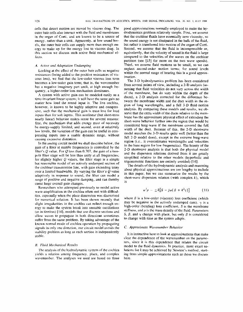
The details of the hydrodynamic analysis and reasoning about physical approximations are too lengthy to include in this paper, but we can summarize the results by the short-wave dispersion relation (with complex k ) , which is
(11) w 2 p = fk[S - j w ( / 3 + k 2 y ) ]
where /3 is a low-order (viscous) loss coefficient (which may be negative in the actively undamped case), y is a high-order (bending) loss coefficient, S is the membrane stiffness, and p is the mass density of the fluid. Parameters S , 0, and y change with place, but only /3 is considered to change with time as the system adapts.
C. Approximate Wavenumber Behavior
It is instructive here to look at approximations that make clear the dependence of the wavenumber on the parame- ters, since it is this dependence that relates the circuit model to the fluid dynamics. In practice, more exact so- lutions fo rk may be achieved by Newton’s method, start- ing from simple approximations such as those we discuss here.
I177
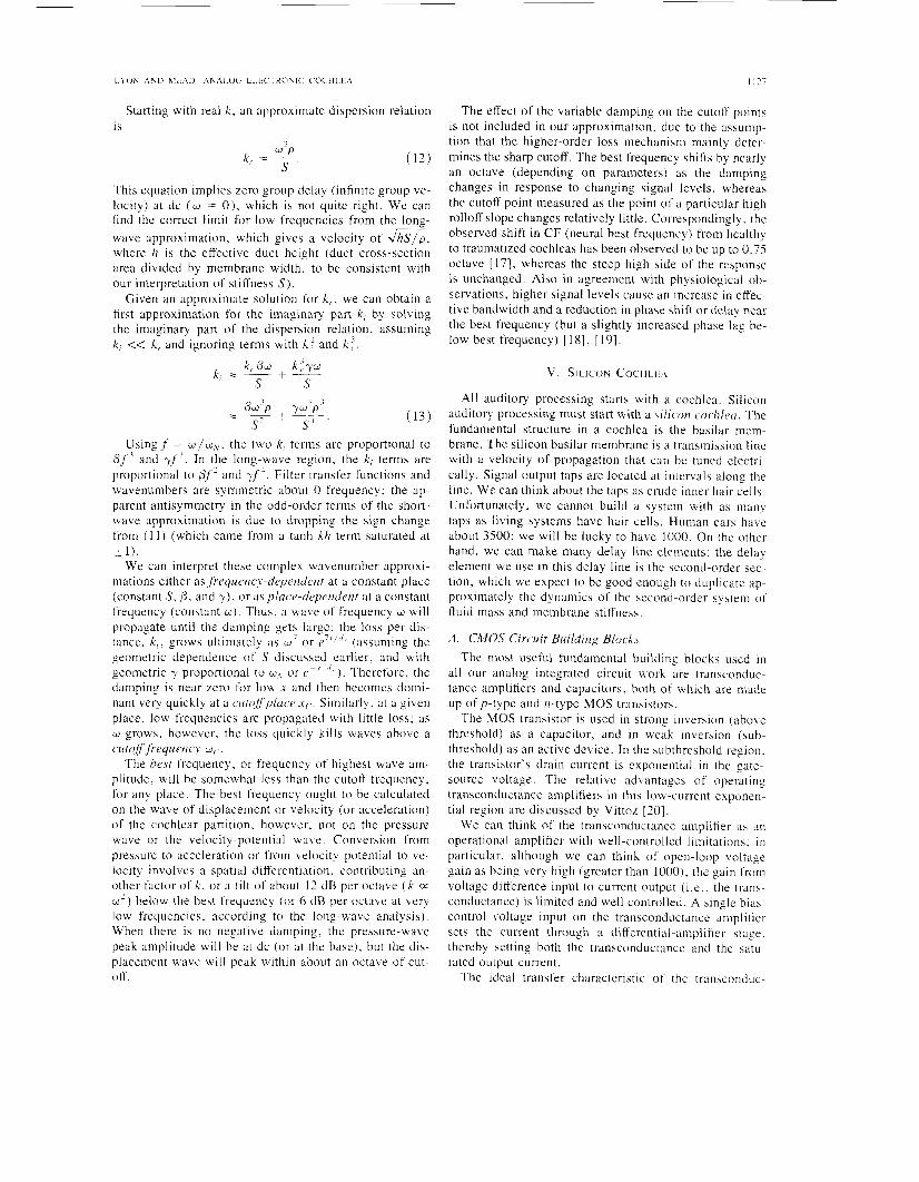
Starting with real k , an approximate dispersion relation 1s
This equation implies zero group delay (infinite group ve- locity) at dc (w = O ) , which is not quite right. We can find the correct limit for low frequencies from the long- wave approximation, which gives a velocity of Jhslp. where lz is the effective duct height (duct cross-section area divided by membrane width. to be consistent with our interpretation of stiffness S).
Given an approximate solution for k , . we can obtain a first approximation for the imaginary part k , by solving the imaginary part of the dispersion relation, assuming k , << k , and ignoring terms with k : and k l .
Usingf = w/w,,,. the two k , terms are proportional to P f 3 and yf ’. In the long-wave region. the k , terms are proportional to pf’ and yf‘. Filter transfer functions and wavenumbers are symmetric about 0 frequency: the ap- parent antisymmetry in the odd-order terms of the short- wave approximation is due to dropping the sign change from (11) (which came from a tanh kh term saturated at i 1).
We can interpret these complex wavenuniber approxi- mations either as freyu(.tzc?.-depc.ndent at a constant place (constant S, P , and y). or aspluc~-depetidetzt at a constant frequency (constant w). Thus, a wave of frequency w will propagate until the damping gets large; the loss per dis- tance, k , , grows ultimately as w7 o r e’‘ ”* (assuming the geometric dependence of S discussed earlier, and with geometric y proportional to U’\. or ( J -
damping is near zero for low .Y and then becomes domi- nant very quickly at a cutc?ffpluc~~ .Y(.. Similarly, at a given place, low frequencies are propagated with little loss; as w grows. however, the loss quickly kills waves above a cutqfffrequency w(- .
The hest frequency, or frequency of highest wave am- plitude, will be somewhat less than the cutoff frequency. for any place. The best frequency ought to be calculated on the wave of displacement or velocity (or acceleration) of the cochlear partition, however, not on the pressure wave or the velocity-potential wave. Conversion from pressure to acceleration or from velocity potential to ve- locity involves a spatial differentiation, contributing an- other factor of k . or a t i l t of about 12 d B per octave ( k a a’) below the best frequency (or 6 dB per octave at very low frequencies. according to the long-wave analysis). When there is no negative damping, the pressure-wave peak amplitude will be at dc (or at the base), but the dis- placement wave will peak within about an octave of cut- off.
The effect of the variable damping on the cutoff points is not included in our approximation. due to the assump- tion that the higher-order loss mechanism mainly deter- mines the sharp cutoff. The best frequency shifts by nearly an octave (depending on parameters) as the damping changes in response to changing signal levels, whereas the cutoff point measured as the point of a particular high rolloff slope changes relatively little. Correspondingly. the observed shift in CF (neural best frequency) from healthy to traumatized cochleas has been observed to be up to 0.75 octave [ 171, whereas the steep high side of the response is unchanged. Also in agreement with physiological ob- servations, higher signal levels cause an increase in effec- tive bandwidth and a reduction in phase shift or delay near the best frequency (but a slightly increased phase lag be- low best frequency) [ 181, [ 191.
v. SILICON C O C H L k A
All auditory processing starts with a cochlea. Silicon auditory processing must start with a silicori cochleci. The fundamental structure in a cochlea is the basilar mem- brane. The silicon basilar membrane is a transmission line with a velocity of propagation that can be tuned electri- cally. Signal output taps are located at intervals along the line. We can think about the taps as crude inner hair cells. Unfortunately, we cannot build a system with as many taps as living systems have hair cells. Human ears have about 3500; we will be lucky to have 1000. On the other hand, we can make many delay line elements; the delay element we use in this delay line is the second-order sec- tion, which we expect to be good enough to duplicate ap- proximately the dynamics of the second-order system of fluid mass and membrane stiffness.
A . CMOS Circuit Builtiirig block^ The most useful fundamental building blocks used in
all our analog integrated circuit work are transconduc- tance amplifiers and capacitors, both of which are made up of p-type and n-type MOS transistors.
The MOS transistor is used in strong inversion (above threshold) as a capacitor, and in weak inversion (sub- threshold) as an active device. In the subthreshold region, the transistor’s drain current is exponential in the gate- source voltage. The relative advantages of operating transconductance amplifiers in this low-current exponen- tial region are discussed by Vittoz [20].
We can think of the transconductance amplifier as an operational amplifier with well-controlled limitations: in particular, although we can think of open-loop voltage gain as being very high (greater than 1000). the gain from voltage difference input to current output ( i . e . . the trans- conductance) is limited and well controlled. A single bias- control voltage input on the transconductance amplifier sets the current through a differential-amplifier stage. thereby setting both the transconductance and the satu- rated output current.
The ideal transfer characteristic of the transconduc-
1128
v+ :
v- 4
JEEE TRANSACTIONS ON ACOUSTICS, SPEECH, AND SIGNAL PROCESSING, VOL. 36, NO. 7, JULY 1988
OUT
tance amplifier, for MOS transistors in the subthreshold region, is
(14) I/+ - v-
VT ZOut = ZB tanh ~
where ZB is the amplifier’s bias current and I/, is a char- acteristic voltage near 40 mV equal to k T/qlc, in which k is Boltzmann’s constant, T is absolute temperature, q is the charge of an electron, and K is a capacitive divider ratio, typically around 0.6, that characterizes how much of the potential change on the gate of a transistor causes a change in surface potential in the channel region of the transistor.
For input voltage differences I/+ - I/_ less than about 40 mV, we can approximate the tanh function as an iden- tity, so that the amplifier is roughly linear with a trans- conductance of I , / VT. For large input differences, the output current saturates smoothly at +IB.
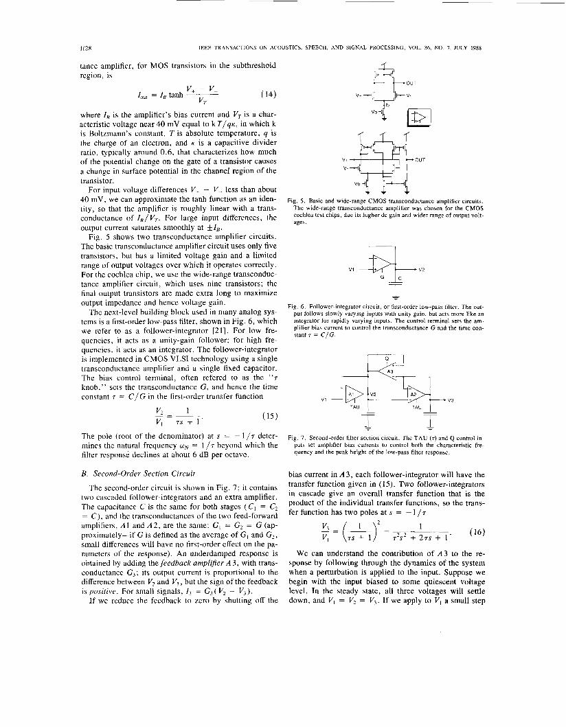
Fig. 5 shows two transconductance amplifier circuits. The basic transconductance amplifier circuit uses only five transistors, but has a limited voltage gain and a limited range of output voltages over which it operates correctly. For the cochlea chip, we use the wide-range transconduc- tance amplifier circuit, which uses nine transistors; the final output transistors are made extra long to maximize output impedance and hence voltage gain.
The next-level building block used in many analog sys- tems is a first-order low-pass filter, shown in Fig. 6, which we refer to as a follower-integrator [21]. For low fre- quencies, it acts as a unity-gain follower; for high fre- quencies, it acts as an integrator. The follower-integrator is implemented in CMOS VLSI technology using a single transconductance amplifier and a single fixed capacitor. The bias control terminal, often refered to as the “7 knob,” sets the transconductance G, and hence the time constant 7 = C/G in the first-order transfer function
1 - v2
I/, 7s + I
The pole (root of the denominator) at s = - 1 /7 deter- mines the natural frequency wN = 1 /7 beyond which the filter response declines at about 6 dB per octave.
B. Second-Order Section Circuit
The second-order circuit is shown in Fig. 7; it contains two cascaded follower-integrators and an extra amplifier. The capacitance C is the same for both stages ( C1 = C, = C), and the transconductances of the two feed-forward amplifiers, A1 and A2, are the same: GI = G2 = G (ap- proximately-if G is defined as the average of GI and G,, small differences will have no first-order effect on the pa- rameters of the response). An underdamped response is obtained by adding the feedback amplifer A 3, with trans- conductance G,; its output current is proportional to the difference between V, and I/,, but the sign of the feedback is positive. For small signals, 1, = G3( V, - I/,).
If we reduce the feedback to zero by shutting off the
V I
Fig. 6. Follower-integrator circuit, or first-order low-pass filter. The out- put follows slowly varying inputs with unity gain, but acts more like an integrator for rapidly varying inputs. The control terminal sets the am- plifier bias current to control the transconductance G and the time con- stant r = C / G .
v1 *q TAU TAU v3
Fig. 7 . Second-order filter section circuit. The TAU (7) and Q control in- puts set amplifier bias currents to control both the characteristic fre- quency and the peak height of the low-pass filter response.
bias current in A 3, each follower-integrator will have the transfer function given in (15). Two follower-integrators in cascade give an overall transfer function that is the product of the individual transfer functions, so the trans- fer function has two poles at s = - 1 / 7
We can understand the contribution of A 3 to the re- sponse by following through the dynamics of the system when a perturbation is applied to the input. Suppose we begin with the input biased to some quiescent voltage level. In the steady state, all three voltages will settle down, and VI = V, = I/,. If we apply to V , a small step
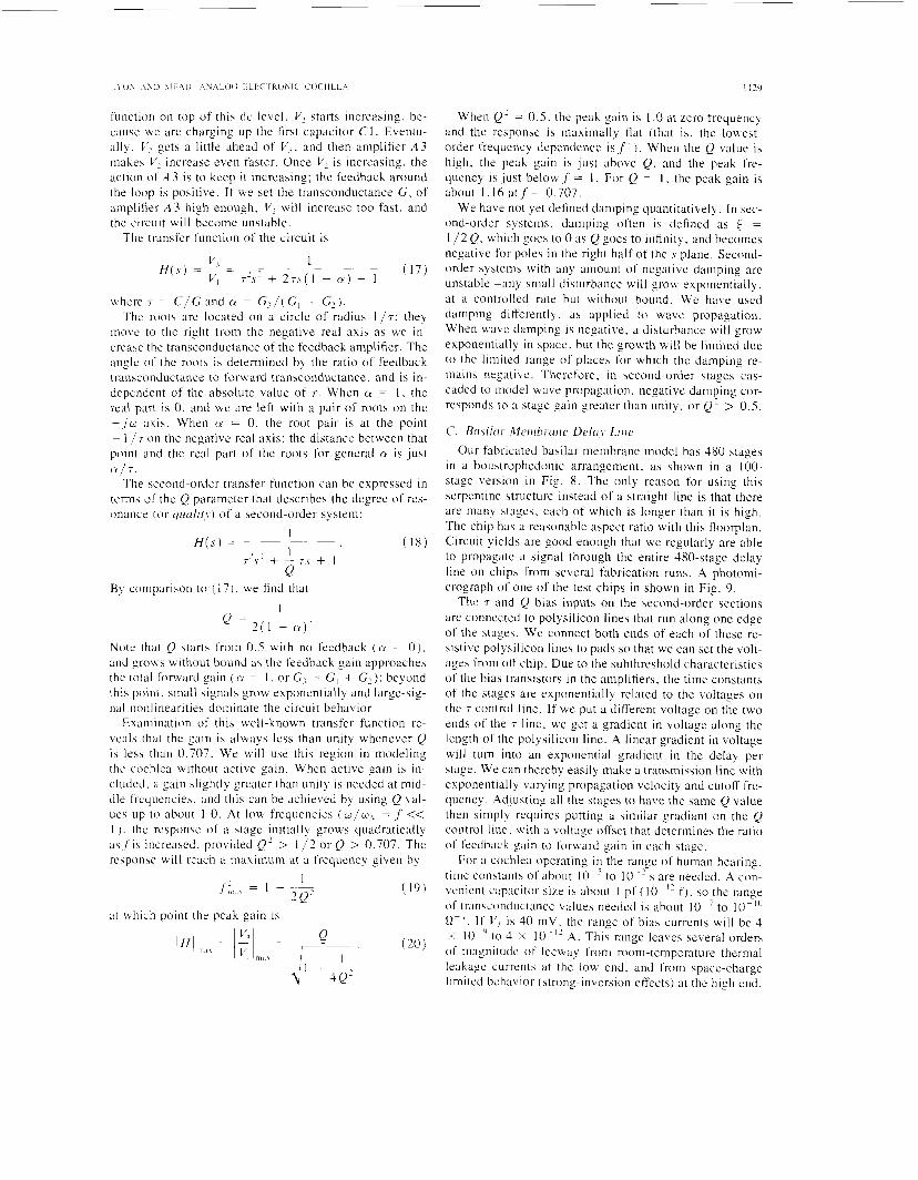
function on top of this tic level. V2 starts increasing, be- cause we are charging up the first capacitor C1. Eventu- ally. V I gets a little ahead of Vi. and then amplifier A 3 niakes V2 increase even faster. Once V2 is increasing. the action of A 3 is to keep it increasing: the feedback around the loop is positive. If we set the transconductance G, of amplifier A 3 high enough, V , will increase too fast, and the circuit will become unstable.
The transfer function of the circuit is
where r = C / G and CY = G, / (G , + G 2 ) . The roots are located on a circle of radius 1 / r : they
move to the right from the negative real axis as we in- crease the transconductance of the feedback amplifier. The angle of' the roots is determined by the ratio of feedback transconductance to forward transconductance, and is in- dependent of the absolute value of 7. When CY = 1 . the real part is 0. and we are left with a pair of roots on the i , j w axis. When CY = 0. the root pair is at the point - 1 / r on the negative real axis; the distance between that point and the real part of the roots for general a is just
The second-order transfer function can be expressed in terms of the Q parameter that describes the degree of res- onance (or quulirj) of a second-order system:
C Y / T .
I H ( s ) = (18 )
By comparison to ( I 7 ) . we find that 1
= 2 ( 1 - a ) '
Note that Q starts from 0.5 with no feedback ( a = 0 ) . and grows without bound as the feedback gain approaches the total forward gain ( a = 1 . or GI = GI + G?): beyond this point. small signals grow exponentially and large-sig- nal nonlinearities dominate the circuit behavior
Examination of this well-known transfer function re- veals that the gain is always less than unity whenever Q is less than 0.707. We will use this region in modeling the cochlea without active gain. When active gain is in- cluded. a gain slightly greatcr than uni ty is needed at mid- dle frequencies. and this can be achieved by using Q val- ues up t o about 1.0. At low frequencies (w/w, = ,f << 1 ) . the response of a stage initially prows quadratically as,f'is increased. provided Q' > I / 2 or Q > 0.707. The response will reach a maximum at a frequency given by
1 f' = I - - - ? @ Ill, ,\
at which point the peak gain is
When Q' = 0.5. the peak gain is I .0 at Lero frequent) and the response is maximally flat (that is. the lowest- order frequency dependence i s f 4 ) . When the Q value is high, the peak gain is ju s t above Q. and the peak fre- quency is just below f = 1. For Q = 1 . the peak gain is about 1.16 atf = 0.707.
We have not yet defined damping quantitatively. In sec- ond-order systems, damping often is defined as t = 1 / 2 Q, which goes to 0 as Q goes to infinity, and becomes negative for poles in the right half of the s plane. Second- order systems with any amount of negative damping are unstable-any small disturbance will grow exponentially, at a controlled rate but without bound. Wc have used damping differently, a s applied to wave propagation. When wave damping is negative, a disturbance will grow exponentially in space. but the growth will be limited due to the limited range of places for which the damping re- mains negative. Therefore, in second-order stages cas- caded to model wave propagation. negative damping cor- responds to a stage gain greater than unity. or Q 2 > 0.5.
C. Btrsilur- M~ri ihr-ar~c Dc~Ioy Liric Our fabricated basilar membrane model has 480 stages
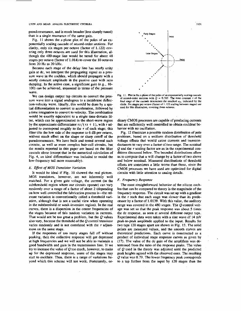
in a boustrophedonic arrangement, as shown in a 100- stage version in Fig. 8 . The only reason for using this serpentine structure instead of a straight line is that there are many stages. each of which is longer than it is high. The chip has a reasonable aspect ratio with this floorplan. Circuit yields are good enough that we regularly are able to propagate a signal through the entire 480-stage delay line on chips from several fabrication runs. A photonii- crograph of one of the test chips in shown in Fig. 9.
The 7 and Q bias inputs on the second-order sections are connected to polysilicon lines that run along one edge of the stages. We connect both ends of each of these re- sistive polysilicon lines to pads so that we can set the volt- ages from off chip. Due to the subthreshold characteristics of the bias transistors in the amplifiers. the time constants of the stages are exponentially related to the voltages on the 7 control line. If we put a different voltage on the two ends of the 7 line, we get a gradient in voltage along the length of the polysilicon line. A linear gradient in voltage will turn into an exponential gradient in the delay per stage. We can thereby easily make a transmission line with exponentially varying propagation velocity and cutoff fre- quency. Adjusting all the stages to have the same Q value then simply requires putting a similar gradiant on the Q control line. with a voltage offset that determines the ratio of feedback gain to forward gain in each stage.
For a cochlea operating in the range of human hearing, time constants of about I O p 5 to 10 ~ ' s are needed. A con- venient capacitor size is about 1 pf ( I O - " f ) . so the range of transconductance values needed is about 10- to IO-" ' R-'. I f V , is 40 mV. the range of bias currents will be 4 X IO-^' to 4 X 10 A. This range leaves several orders of magnitude of I ee w ay from rooni - t e in pe ra t u re the nn a I leakage currents at the low end. and from space-charge limited behavior (strong-inversion effects) at the high end,
1130 IEEE TRANSACTIONS ON ACOUSTICS, SPEECH, AND SIGNAL PROCESSING, VOL. 36. NO. 7. JULY 1988
output T~~~ Second-Order Section. In @r out
Fig. 8. Floorplan of 100-stage cochlea chip, in serpentine arrangement. The wires that are shown connecting the TAU and Q control terminals of the filter stages are built using a resistive polysilicon line, to act as a voltage divider that adjusts the bias currents in the cascade as an expo- nential function of distance from the input.
Tau
wlth Followers Q2
Fig. 9. Photomicrograph of 480-stage cochlea test chip. The large project in the bottom two-thirds of this MOSIS die is the cochlea. The pads visible on the left and right edges are for output taps, and on the bottom edge are for the other signals shown in Fig. 8.
so the circuits are in many ways ideal. The total current supplied to a cascade of 480 stages is only about a mi- croampere.
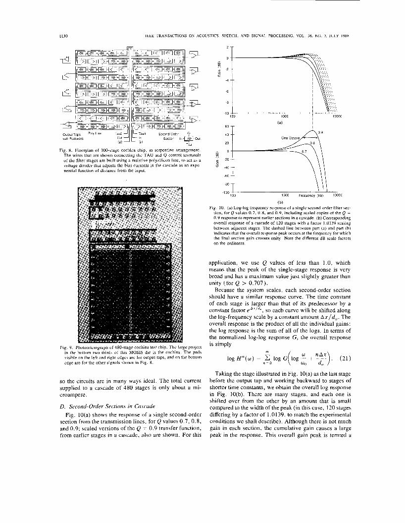
D. Second-Order Sections in Cascade Fig. 10(a) shows the response of a single second-order
section from the transmission lines, for Q values 0.7, 0.8, and 0.9; scaled versions of the Q = 0.9 transfer function, from earlier stages in a cascade, also are shown. For this
0 is 9
k 2 4
6
-8
-10 100 1000 10000
I /
100 1000 Frequency (Hz) 10000 -100 !
(b) Fig. IO. (a) Log-log frequency response of a single second-order filter sec-
tion, for Q values 0.7, 0.8, and 0.9, including scaled copies of the Q = 0.9 response to represent earlier sections in a cascade. ( b ) Corresponding overall response of a cascade of 120 stages with a factor 1.0139 scaling between adjacent stages. The dashed line between part (a) and part (b) indicates that the overall response peak occurs at the frequency for which the final section gain crosses unity. Note the different dB scale factors on the ordinates.
application, we use Q values of less than 1.0, which means that the peak of the single-stage response is very broad and has a maximum value just slightly greater than unity (for Q > 0.707).
Because the system scales, each second-order section should have a similar response curve. The time constant of each stage is larger than that of its predecessor by a constant factor eAx/dw, so each curve will be shifted along the log-frequency scale by a constant amount A x l d , . The overall response is the product of all the individual gains; the log response is the sum of all of the logs. In terms of the normalized log-log response G, the overall response is simply
m
logH"(w) = C log G n = O
Taking the stage illustrated in Fig. 10(a) as the last stage before the output tap and working backward to stages of shorter time constants, we obtain the overall log response in Fig. 10(b). There are many stages, and each one is shifted over from the other by an amount that is small compared to the width of the peak (in this case, 120 stages differing by a factor of 1 .O 139, to match the experimental conditions we shall describe). Although there is not much gain in each section, the cumulative gain causes a large peak in the response. This overall gain peak is termed a
LYON AND MEAD: ANALOG ELECTRONIC COCHLEA
pseudoresonance, and is much broader {less sharply tuned) than is a single resonance of the same gain.
Fig. 11 shows the s-plane plot of the poles of an ex- ponentially scaling cascade of second-order sections. For clarity, only six stages per octave (factor of 1.122) cov- ering only three octaves are used for this illustration, al- though the 480-stage line would be tuned for about 48 stages per octave (factor of 1.014) to cover the 10 octaves from 20 Hz to 20 kHz.
Because each stage of the delay line has nearly unity gain at dc, we interpret the propagating signal as a pres- sure wave in the cochlea, which should propagate with a nearly constant amplitude in the passive case with zero damping. In the active case, a significant gain (e.g., 10- 100) can be achieved, measured in terms of the pressure wave.
We can design output tap circuits to convert the pres- sure wave into a signal analogous to a membrane deflec- tion-velocity wave. Ideally, this would be done by a spa- tial differentiation to convert to acceleration, followed by a time integration to convert to velocity. The combination would be exactly Nuivalent to a single time-domain fil- ter, which can be approximated in the short-wave region by the approximate differentiator m/( 7s + 1 ), with 7 ad- justed to correspond roughly to the 7 of each stage; this filter tilts the low side of the response to 6 dB per octave, without much effect on the shape or sharp cutoff of the pseudoresonance. We have built and tested several such circuits, as well as more complex hair-cell circuits, but the results reported in this paper are based on the filter cascade alone (except that in the numerical calculation of Fig. 4, an ideal differentiator was included to model the low-frequency tail more reasonably).
E. Effect of MOS Transistor Variation It would be ideal if Fig. 10 showed the real picture.
MOS transistors, however, are not inherently well matched. For a given gate voltage, the current (in the subthreshold region where our circuits operate) can vary randomly over a range of a factor of about 2 (depending on how well controlled the fabrication process is-the rel- evant variation is conventionally called a threshold vari- ation, although that is not a useful view when operating in the subthreshold or weak-inversion region). In the real curves, there is a dispersion in the center frequencies of the stages because of this random variation in currents. That would not be too great a problem, but the Q values also vary, because the threshold of the Q control transistor varies randomly and is not correlated with the 7 adjust- ment on the same stage.
If the responses of too many stages fall off without peaking, then the collective response will get depressed at high frequencies and we will not be able to maintain a good bandwidth and gain in the transmission line. If we try to increase the value of Q too much, however, to make up for the depressed response, some of the stages may start to oscillate. Thus, there is a range of variations be- yond which this scheme will not work. Fortunately, or-
* EaliyStages
1131
. i /
/
Fig. 1 1 . Plot in the s-plane of the poles of an exponentially scaling cascade of second-order sections with Q = 0.707. The time constant 7 of the final stage of the cascade determines the smallest uNr indicated by the circle. Six stages per Octave (factor of 1.122 scaling between stages) are used for this illustration, covering three octaves.
dinary CMOS processes are capable of producing currents that are sufficiently well controlled to obtain cochlear be- havior with ndoscillation.
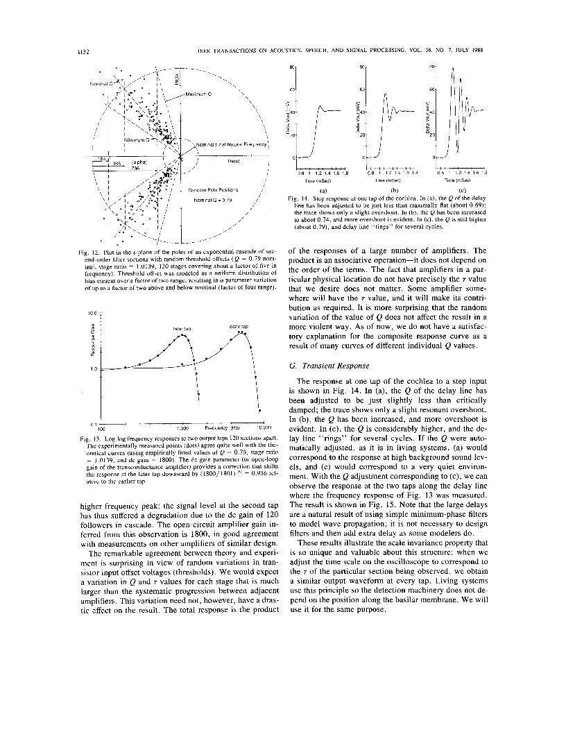
Fig. 12 illustrates a possible random distribution of pole positions, based on a uniform distribution of threshold voltage offsets that would cause currents and transcon- ductances to vary over a factor of two range. The nominal Q and the 7 scaling factor are as in the experimental con- ditions discussed below. The bounded distributions allow us to compute that a will change by a factor of two above and below nominal. Measured distributions of threshold offsets are sometimes a little worse than these, since the CMOS processes we have used are optimized for digital circuits with little attention to analog details.
F. Frequency Response The most straightforward behavior of the silicon coch-
lea that can be compared to theory is the magnitude of the frequency response. The circuit was set up with a gradient in the 7 such that each stage was slower than its prede- cessor by a factor of 1.0139. With this value, the auditory range was covered in the 480 stages. The Q-control volt- age was set so that the peak response was about 5 times the dc response, as seen at several different output taps. Experimental data were taken with a sine wave of 14 mV peak-to-peak amplitude applied to the input. Results for two taps 120 stages apart are shown in Fig. 13. The solid points are measured values, and the smooth curves are theoretical predictions. Each curve is constructed as a product of individual stage response curves as given by (17). The value of the dc gain of the amplifiers was de- termined from the ratio of the response peaks. The value of Q used in the theory was adjusted until the predicted peak heights agreed with the observed ones. The resulting Q value was 0.79. The lower frequency peak corresponds to a tap further from the input by 120 stages than the
1132
t
I
IEEE TRANSACTIONS ON ACOUSTICS, SPEECH, AND SIGNAL PROCESSING. VOL. 36. NO. 7, JULY 1988
. . . \ \
\ \
\ -Maximum 0 \
\ \ \ \ \ \ \ \ - \
‘\ Nominal Final Natural Frequency‘
I I 1 I
I I
/ /
I
/‘, W s )
/ , c
Random Pole Positions / /
Nominal 0 = 0.79 / /
/ /
/ /
/ /
,/ , /’
Fig. 12. Plot in the s-plane of the poles of an exponential cascade of sec- ond-order filter sections with random threshold offsets ( Q = 0.79 nom- inal, stage ratio = 1,0139, 120 stages covering about a factor of five in frequency). Threshold offset was modeled as a uniform distribution of bias current over a factor of two range, resulting in CY parameter variation of up to a factor of two above and below nominal (factor of four range).
higher frequency peak; the signal level at the second tap has thus suffered a degradation due to the dc gain of 120 followers in cascade. The open-circuit amplifier gain in- ferred from this observation is 1800, in good agreement with measurements on other amplifiers of similar design.
The remarkable agreement between theory and experi- ment is surprising in view of random variations in tran- sistor input offset voltages (thresholds). We would expect a variation in Q and 7 values for each stage that is much larger than the systematic progression between adjacent amplifiers. This variation need not, however, have a dras- tic effect on the result. The total response is the product
60 60
80
60
0 8 1 1 . 2 1 . 4 1 . 6 1 8 0.8 1 1 2 1 4 1 6 1 . 8 0 8 1 1 2 1 4 1 6 1 8
Time (mSec) Time (mSec) Time (mSec)
(a) (b) (C) Fig. 14. Step response at one tap of the cochlea. In (a), the Q of the delay
line has been adjusted to be just less than maximally flat (about 0.69); the trace shows only a slight overshoot. In (b), the Q has been increased to about 0.74, and more overshoot is evident. In (c), the Q is still higher (about 0.79), and delay line “rings” for several cycles.
of the responses of a large number of amplifiers. The product is an associative operation-it does not depend on the order of the terms. The fact that amplifiers in a par- ticular physical location do not have precisely the 7 value that we desire does not matter. Some amplifier some- where will have the 7 value, and it will make its contri- bution as required. It is more surprising that the random variation of the value of Q does not affect the result in a more violent way. As of now, we do not have a satisfac- tory explanation for the composite response curve as a result of many curves of different individual Q values.
G. Transient Response
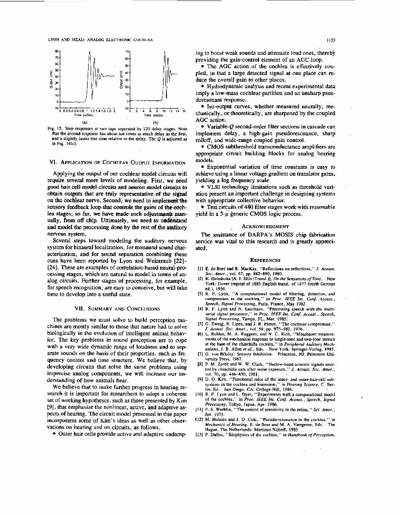
The response at one tap of the cochlea to a step input is shown in Fig. 14. In (a), the Q of the delay line has been adjusted to be just slightly less than critically damped; the trace shows only a slight resonant overshoot. In (b), the Q has been increased, and more overshoot is evident. In (c), the Q is considerably higher, and the de- lay line “rings” for several cycles. If the Q were auto- matically adjusted, as it is in living systems, (a) would correspond to the response at high background sound lev- els, and (c) would correspond to a very quiet environ- ment. With the Q adjustment corresponding to (c), we can observe the response at the two taps along the delay line where the frequency response of Fig. 13 was measured. The result is shown in Fig. 15. Note that the large delays are a natural result of using simple minimum-phase filters to model wave propagation; it is not necessary to design filters and then add extra delay as some modelers do.
These results illustrate the scale invariance property that is so unique and valuable about this structure: when we adjust the time scale on the oscilloscope to correspond to the 7 of the particular section being observed, we obtain a similar output waveform at every tap. Living systems use this principle so the detection machinery does not de- pend on the position along the basilar membrane. We will use it for the same purpose.
LYON AND MEAD: ANALOG ELECTRONIC COCHLEA 1133
230 O 20 .iL 10
70 T
A 0204060’8 i 1‘2 1’4 1’6 1’8 -lo; 2 4 6 8 10 1’2 1; 16 -10
Time (mSec) Time @Sec)
(a) (b) Fig. 15. Step responses at two taps separated by 120 delay stages. Note
that the second response has about ten times as much delay as the first, and a slightly faster rise time relative to the delay. The Q is adjusted as in Fig. 14(c).
VI. APPLICATION OF COCHLEAR OUTPUT INFORMATION
Applying the output of our cochlear model circuits will require several more levels of modeling. First, we need good hair cell model circuits and neuro obtain outputs that are truly representative of the on the cocwear nerve. Second, we wed to im sensory f&back loop that C o n t d s the lea stages; so far, we have made such ually, from off chip. Ultimately, we n and model the processing done by the res nervous system.
Several steps toward modeling the auditory nervous system for binaural localization, for monaural sound char- acterization, and for sound separation combining these cues have been reported by Lyon and Weintraub [22]- [24]. These are examples of correlation-based neural-pro- cessing stages, which are natural to model in terms of an- alog circuits. Further stages of processing, for example, for speech recognition, are easy to conceive, but will take time to develop into a useful state.
VII. SUMMARY AND CONCLUSIONS
The problems we must sdlve to build perception ma- chines are mostly similar to those that nature had to solve biologically in the evolution of intelligent animal behav- ior. The key problems in sound perception are to cope with a very wide dynamic range of loudness and to sep- arate sounds on the basis of their properties, such as fre- quency content and time structure. We believe that, by developing circuits that solve the same problems using imprecise analog components, we will increase our un- derstanding of how animals hear.
We believe that to make further progress in hearing re- search it is important for researchers to adopt a coherent set of working hypotheses, such as those presented by Kim [9], that emphasize the nonlinear, active, and adaptive as- pects of hearing. The circuit model presented in this paper incorporates some of Kim’s ideas as well as other obser- vations on hearing and on circuits, as follows.
Outer hair cells provide active and adaptive undamp-
ing to boost weak sounds and attenuate loud ones, therebi providing the gain-control element of an AGC loop.
The AGC action of the cochlea is effectively cou- pled, in that a large detected signal at one place can re- duce the overall gain to other places.
Hydrodynamic analysis and recent experimental data imply a low-mass cochlear partition and an unsharp pseu- doresonant response.
Iso-output curves, whether measured neurally, me- chanically, or theoretically, are sharpened by the coupled AGC action.
Variable-Q second-order filter sections in cascade can implement delay, a high-gain pseudoresonance, sharp rolloff, and wide-range coupled gain control.
CMOS subthreshold transconductance amplifiers are appropriate circuit building blocks for analog hearing models.
Exponential variation of time constants is easy to achieve using a linear voltage gradient on transistor gates, yielding a log frequency scale.
VLSI technology limitations such as threshold vari- ation present an important challenge in designing systems with appropriate collective behavior.
Test circuits of 480 filter stages work with reasonable yield in a 3-p generic CMOS logic process.
ACKNOWLEDGMENT The assistance of DARPA’s MOSIS chip fabrication
service was vital to this research and is greatly appreci- ated.
REFERENCES [ I ] E. de Boer and R. MacKay, “Reflections on reflections,” J . Acousr.
Soc. Amer., vol. 67, pp. 882-890, 1980. [2] H. Helmholtz [A. J. Ellis (Transl.)], On rhe Sensarions of Tone. New
York: Dover (reprint of 1885 English transl. of 1877 fourth German ed.), 1954.
[3] R. F. Lyon, “A computational model of filtering, detection, and compression in the cochlea,” in Proc. IEEE Inr. Conf. Acousr., Speech, Signal Processing, Pans, France, May 1982.
[4] R. F. Lyon and N. Lauritzen, “Processing speech with the multi- serial signal processor,” in Proc. IEEE Inr. Conj Acousr., Speech, Signal Processing, Tampa, FL, Mar. 1985.‘
[5] G. Zweig, R. Lipes, and J. R. Pierce, “The cochlear compromise,’’ J. Acousr. Soc. Amer., vol. 59, pp. 975-982, 1976.
[6] L. Robles, M. A. Ruggero, and N. C. Rich, “Mossbauer measure- ments of the mechanical response to single-tone and two-tone stimuli at the base of the chinchilla cochlea,” in Peripheral Audirory Mech- anisms, J. B. Allen et a l . , Eds. New York: Springer-Verlag, 1985.
[7] G. von BCkCsy, Sensory Inhibition. Princeton, NJ: Princeton Uni- versity Press, 1967.
[8] P. M. Zurek and W. W. Clark, “Narrow-band acoustic signals emit- ted by chinchilla ears after noise exposure,” J. Acousr. Soc. Amer.,
[9] D. 0. Kim, “Functional roles of the inner- and outer-hair-cell sub- systems in the cochlea and brainstem,” in Hearing Science, C. Ber- lin, Ed.
[ lo] R. F. Lyon and L. Dyer, “Experiments with a computational model of the cochlea,” in Proc. IEEE Inr. Conj Acousr., Speech, Signal Processing, Tokyo, Japan, Apr. 1986.
[ l l ] F. S. Werblin, “The control of sensitivity in the retina,” Sci. Amer., Jan. 1973.
[12] M. Holmes and J. D. Cole, “Pseudo-resonance in the cochlea,” in Mechanics of Hearing, E. de Boer and M. A. Viergever, Eds. The Hague, The Netherlands: Martinus Nijhoff, 1983.
[13] P. Dallos, “Biophysics of the cochlea,” in Handbook of Perception,
vol. 70, pp. 446-450, 1981.
San Diego, CA: College-Hill, 1984.

1134 IEEE TRANSACTIONS ON ACOUSTICS, SPEECH, AND SIGNAL PROCESSING, VOL. 36, NO. 7. JULY 1988
vol. IV, E. C. Carterette and M. P. Friedman, Eds. New York: Academic, 1978, ch. 4. E. de Boer, “Wave reflection in passive and active cochlea models,” in Mechanics ofHearing, E. de Boer and M. A. Viergever, Eds. The Hague, The Netherlands: Martinus Nijhoff, 1983. J. Lighthill, “Energy flow in the cochlea,” J . Fluid Mech., vol. 106,
R. F. Lyon and C. A. Mead, “Cochlear hydrodynamics demysti- fied,” Caltech Comput. Sci. Tech. Rep. Caltech-CS-TR-884, Pasa- dena, CA, Feb. 1988. A. R. Cody and B. M. Johnstone, “Single auditory neuron response during acute acoustic trauma,” Hearing Res., vol. 3, pp. 3-16, 1980. J. 0. Pickles, “Recent advances in cochlear physiology,” Prog. Neu- robiol., vol. 24, pp. 1-42, 1985. P. M. Sellick, R. Patuzzi, and B. M. Johnstone, “Measurement of basilar membrane motion in the guinea pig using the Mossbauer tech- nique,” J . Acoust. Soc. Amhr., vol. 72, pp. 131-141, 1982. E. A. Vittoz, “Micropower techniques,” in Design of MOS VLSI Circuitsfor Telecommunications; Y. Tsividis and P. Antognetti, Eds. Englewood Cliffs, NJ: Prentice-Hall, 1985, ch. 4. C . A. Mead, Analog VLSI and Neural Systems. Reading, MA: Ad- dison-Wesley (in press). R. F. Lyon, “A computational model of binaural localization and separation,” in Proc. IEEE Int. Con$ Acoust., Speech, Signal Pro- cessing, Boston, MA, Apr. 1983. - , “Computational models of neural auditory processing,” in Proc.
pulsion Laboratory, Stanford Telecommunications Inc., Xerox PARC, and Schlumberger Palo Alto Research. In his current position at Apple Com- puter, he is involved in research in speech recognition using models of hearing. He is also currently on the Computer Science Faculty at Caltech, where he works on sensory modeling research and analog VLSI techniques for signal processing.
pp. 149-213, 1981.
IEEE Int. COn8 Mar. 1984. M. Weintraub, IEEE Int. Con8 Mar. 1984.
Acousr., Speech, Signal Processing, SanDiego, CA,
“The GRASP sound separation system,” in Proc. Acoust., Speech, Signal Processing, San Diego, CA,
Richard F. Lyon (M’78) received the B.S. de- gree in engineering and applied science from cal- ifomia Institute of Technology, Pasadena, in 1974, and the M.S. degree in electrical engineer- ing from Stanford University, Stanford, CA, in 1975.
He has worked on a variety of projects involv- ing communication and information theory, digi- tal system design, analog and digital signal pro- cessing, VLSI design and methodologies, and sensory perception at Caltech, Bell Labs, Jet Pro-
Carver Mead is the Gordon and Betty Moore Professor of Computer Science, and has taught at the California Institute of Technology, Pasadena, for over 20 years. He worked in the fields of solid- state electronics and the management of complex- ity in the design of very large scale integrated cir- cuits, and has been a leading force in the devel- opment of a design methodology for VLSI. He has written, with L. Conway, the standard text for VLSI design, Introduction to VLSI Systems. His recent work is concerned with modeling neuronal
structures, such as the retina or the cochlea, using analog VLSI systems. His new book on this topic, Analog VLSI and Neural Systems, is to appear in 1988.
Prof. Mead is a Fellow of the American Physical Society, a member of the National Academy of Engineering, foreign member of the Royal Swed- ish Academy of Engineering Science, and has been elected to Life Mem- bership in the Franklin Institute.