ertms regional grs - uic · pdf filesrs system requirements specification ... tcc to...
TRANSCRIPT
ERTMS Regional
ERTMS Regional General Technical Requirements Specification, draft 01.02 1
ERTMS Regional General Technical Requirements Specification
GRS Version: 01.00 DRAFT 1.02 20-01-06 Number of Pages: 30 Filing Number: 16112005
Restricted condition © 2006 by UIC, all rights reserved Copyright subsists in all UIC/ERTMS/ETCS specifications including magnetic, optical and/or any other soft copy of these specifications. This document may not be reproduced, in full or in part, without written permission. Enquires about copyright of UIC/ERTMS/ETCS specifications should be made to the UIC, 16, rue Jean Rey, F 75015 PARIS If, by permission of the copyright owner, any part of this document is quoted, then a statement specifying the original document shall be added to the quotation. Any such quotation shall be according to the original (text, figure or table) and may not be shortened or modified. See note added to modification history section.
ERTMS Regional
ERTMS Regional General Technical Requirements Specification, draft 01.02 2
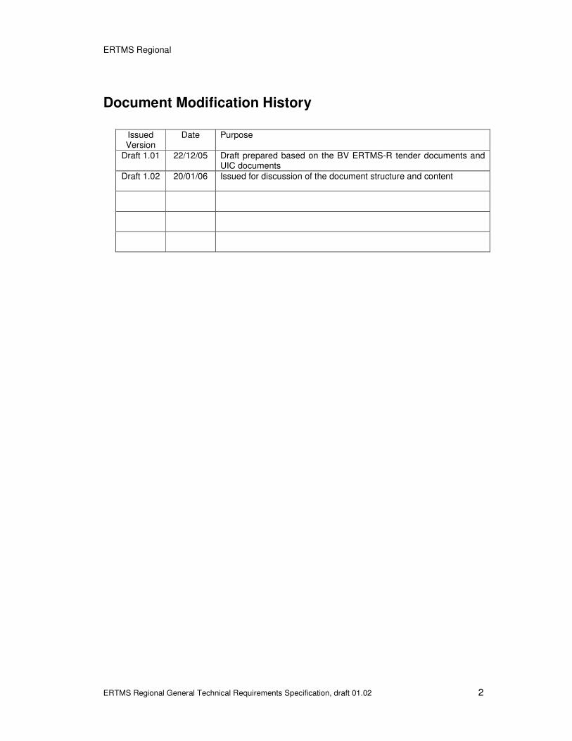
Document Modification History
Issued Version
Date Purpose
Draft 1.01 22/12/05 Draft prepared based on the BV ERTMS-R tender documents and UIC documents
Draft 1.02 20/01/06 Issued for discussion of the document structure and content
ERTMS Regional
ERTMS Regional General Technical Requirements Specification, draft 01.02 3
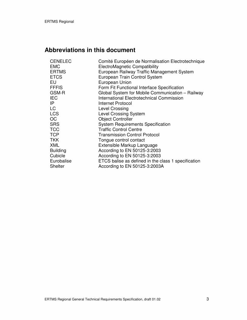
Abbreviations in this document
CENELEC Comité Européen de Normalisation Electrotechnique EMC ElectroMagnetic Compatibility ERTMS European Railway Traffic Management System ETCS European Train Control System EU European Union FFFIS Form Fit Functional Interface Specification GSM-R Global System for Mobile Communication – Railway IEC International Electrotechnical Commission IP Internet Protocol LC Level Crossing LCS Level Crossing System OC Object Controller SRS System Requirements Specification TCC Traffic Control Centre TCP Transmission Control Protocol TKK Tongue control contact XML Extensible Markup Language Building According to EN 50125-3:2003 Cubicle According to EN 50125-3:2003 Eurobalise ETCS balise as defined in the class 1 specification Shelter According to EN 50125-3:2003A

ERTMS Regional
ERTMS Regional General Technical Requirements Specification, draft 01.02 4
Table of contents
DOCUMENT MODIFICATION HISTORY ............................................................. 2 ABBREVIATIONS ................................................................................................ 3 TABLE OF CONTENTS ....................................................................................... 4 1. INTRODUCTION ........................................................................................... 5 2. APPLICABLE STANDARDS ........................................................................ 6 2.1 ERTMS/ETCS documents ................................................................................................. 6 2.2 CENELEC documents ....................................................................................................... 6 2.3 National documents .......................................................................................................... 6 3. SYSTEM DESCRIPTION............................................................................... 7 3.1 Interface IA: TCC to Administration System................................................................... 7 3.2 Interface IB: TCC to Juridical Recorder System ............................................................ 7 3.3 Interface IC: TCC to Maintenance System ...................................................................... 7 3.4 Interface ID: TCC to Controller System........................................................................... 8 3.5 Interface IE: TCC to External Information System ......................................................... 8 3.6 Interface IF: TCC to Data Preparation System................................................................ 8 3.7 Interface IG: TCC to Hand Held Terminal ........................................................................ 8 3.8 Interface IH: TCC system to Object Controller ............................................................... 8 3.9 Interface II: TCC to Other TCC.......................................................................................... 9 3.10 Interface EA: TCC system to Passenger Train Warning System.................................. 9 3.11 Interface EB: TCC system to Adjacent CTC ................................................................... 9 3.12 Interface EC: Train Position Information ........................................................................ 9 3.13 Interface ED: TCC system to ETCS train......................................................................... 9 3.14 Interface EE: TCC system to Adjacent RBC ................................................................... 9 3.15 Interface EF: TCC system to Detector PC....................................................................... 9 3.16 Interface EG: Object Controller to Electrical Point / Derailer...................................... 10 3.17 Interface EH: Object Controller to Level Crossing System......................................... 12 3.18 Interface EI: Object Controller to Adjacent Interlocking ............................................. 13 3.19 Interface EJ: Object Controller to Electrical Point Lock ............................................. 13 3.20 Interface EK: Object Controller to Generic Input / Output .......................................... 14 3.21 Interface EL: Object Controller to Track Circuit........................................................... 15 3.22 Interface EM: Object Controller to Point Heater........................................................... 16 3.23 Interface EN: Eurobalise to ETCS train ......................................................................... 17 3.24 Interface EO: Power Supply ........................................................................................... 17 4. SYSTEM REQUIREMENTS .........................................................................18 4.1 Start-up and restart ......................................................................................................... 18 4.2 Stand-by ........................................................................................................................... 18 4.3 Performance..................................................................................................................... 18 4.4 Capacity............................................................................................................................ 21 5. ENVIRONMENT ...........................................................................................21 5.1 Introduction...................................................................................................................... 21 5.2 Environmental conditions .............................................................................................. 21 5.3 Environmental pollution/contamination........................................................................ 24 5.4 EMC................................................................................................................................... 25 5.5 CE certificate.................................................................................................................... 25 6. DESIGN........................................................................................................26 6.1 Spare Capacity................................................................................................................. 26 6.2 Date and Time .................................................................................................................. 26 6.3 Grounding ........................................................................................................................ 26 6.4 Cables and Network ........................................................................................................ 26 6.5 Qualitative requirements ................................................................................................ 26 7. REFERENCES .............................................................................................28 8. ANNEX A......................................................................................................29 9. ANNEX B......................................................................................................30
ERTMS Regional
ERTMS Regional General Technical Requirements Specification, draft 01.02 5
1. Introduction
This document, General Technical Requirements Specifications (GRS), specifies the general technical requirements for the ERTMS Regional system, with functionality as described in the ERTMS Regional FRS-document (version 03.00 31-10-2003), to be used by the UIC Railways. The purpose of the document is to define non-functional requirements/specifications such as system interfaces, performance, environment, etc. With each of the requirements, an “(R)” is indicated to separate them clearly from explanations and other informative text. Explanations and notes are not marked “(R)” is information for clarification and shall not be regarded as requirements.

ERTMS Regional
ERTMS Regional General Technical Requirements Specification, draft 01.02 6
2. Applicable standards
2.1 ERTMS/ETCS documents
The ERTMS Regional system shall comply with the ERTMS/ETCS class 1 and the GSM-R specification, according to Annex A (R).
2.2 CENELEC documents
The ERTMS Regional system shall comply with the documents listed below (R). Document Name Reference
Railway applications - Communication, signalling and processing systems -- Part 2: Safety related communication in open transmission systems
EN 50159-2:2001
Railway applications - Insulation coordination -- Part 1: Basic requirements - Clearances and creepage distances for all electrical and electronic equipment
EN 50124-1:2001
Addition of an informative annex to EN (Application guide on insulation coordination and creepage distances)
EN 50124- 1:2001/prAA:2003
Table 1 – List of CENELEC documents.
2.3 National documents
The ERTMS Regional system shall comply with the documents listed below (R). Document Name Reference
Table 2 – List of National documents.

ERTMS Regional
ERTMS Regional General Technical Requirements Specification, draft 01.02 7
3. System description
The following figure describes the ERTMS Regional system architecture and its boundaries.
Figure 1 –ERTMS Regional system architecture.
3.1 Interface IA: TCC to Administration System
The interface IA shall be based on the IP protocol (R). The interface IA shall be Ethernet based with a RJ45 connection (R). A FFFIS for interface IA shall be developed as part of the SRS in cooperation with the Purchaser (R).
3.2 Interface IB: TCC to Juridical Recorder System
A FFFIS for interface IB shall be developed as part of the SRS in cooperation with the Purchaser (R).
3.3 Interface IC: TCC to Maintenance System
The interface IC shall be based on the IP protocol (R). The interface IC shall be Ethernet based with a RJ45 connection (R). A FFFIS for interface IC shall be developed as part of the SRS in cooperation with the Purchaser (R).

ERTMS Regional
ERTMS Regional General Technical Requirements Specification, draft 01.02 8
3.4 Interface ID: TCC to Controller System
The interface ID shall be based on the IP protocol (R). The interface ID shall be Ethernet based with a RJ45 connection (R). A FFFIS for interface ID shall be developed as part of the SRS in cooperation with the Purchaser (R).
3.5 Interface IE: TCC to External Information System
The interface IE shall be based on the IP protocol (R). A FFFIS for interface IE shall be developed as part of the SRS in cooperation with the Purchaser (R).
3.6 Interface IF: TCC to Data Preparation System
It shall be possible to download program/data in the TCC system and its sub-systems using a standard communications protocol (R). If the system used for program/data loading is a computer, then it shall be based on a standard platform (R).
3.7 Interface IG: TCC to Hand Held Terminal
The interface IG shall use GSM-R (R). A FFFIS for interface IG shall be developed as part of the SRS in cooperation with the Purchaser (R). The Hand Held Terminal shall be portable (R).
3.8 Interface IH: TCC system to Object Controller
The interface IH shall be based on the TCP/IP protocol (R). The interface IH shall be Ethernet based with a RJ45 connection (R). A FFFIS for interface IH shall be developed as part of the SRS in cooperation with the Purchaser (R). It shall be possible to implement interface IH on a fixed IP network and on a GPRS network (R). The interface IH shall be compatible with a connection that supports a maximum data rate of 9.6 Kbits/sec (R).

ERTMS Regional
ERTMS Regional General Technical Requirements Specification, draft 01.02 9
3.9 Interface II: TCC to Other TCC
The interface II shall comply with the ERTMS/ETCS class 1 specification, according to Annex A (R). The interface II shall be based on the IP protocol (R). The interface II shall be Ethernet based with a RJ45 connection (R). A FFFIS for interface II shall be developed as part of the SRS in cooperation with the Purchaser (R).
3.10 Interface EA: TCC system to Passenger Train Warning System
The interface EA shall be based on the IP protocol (R). The interface EA shall be Ethernet based with a RJ45 connection (R). A FFFIS for interface EA shall be developed as part of the SRS in cooperation with the Purchaser (R).
3.11 Interface EB: TCC system to Adjacent CTC
The interface EB shall comply with the national standard for the interface ”-( reference to national standard to be included )-“ (R)
3.12 Interface EC: Train Position Information
The interface EC shall be based on the IP protocol (R). The interface EC shall be Ethernet based with a RJ45 connection (R). A FFFIS for interface EC shall be developed as part of the SRS in cooperation with the Purchaser (R).
3.13 Interface ED: TCC system to ETCS train
The interface ED shall comply with the ERTMS/ETCS class 1 specification, according to Annex A (R).
3.14 Interface EE: TCC system to Adjacent RBC
The interface EE shall comply with the ERTMS/ETCS class 1 specification, according to Annex A (R).
3.15 Interface EF: TCC system to Detector PC
The interface EF shall be based on the IP protocol (R).

ERTMS Regional
ERTMS Regional General Technical Requirements Specification, draft 01.02 10
The interface EF shall be Ethernet based with a RJ45 connection (R). A FFFIS for interface EF shall be developed as part of the SRS in cooperation with the Purchaser (R).
3.16 Interface EG: Object Controller to Electrical Point / Derailer
3.16.1 Introduction
An electrical point/derailer operates through commands given by the Object Controller. The point/derailer position is checked by the Object Controller through the use of contacts in the point machine and in the point’s tongue (TKKs). To be able to control the point/derailer locally, a local control terminal will be used.
3.16.2 Point machine
Physical interface
The Object Controller EG interface shall be compatible with the point machine physical interface described in this section (R). {National description to be included example from the Swedish Project in annex xx }
Electrical interface
The Object Controller EG interface shall be compatible at least with one of the point machine electrical interfaces described in this section (R). {National description to be included example from the Swedish Project in annex xx } The Object Controller EG interface shall be able to handle a not-detected status produced by the point machine when a train passes through or approaches the point (R). The Object Controller EG interface shall be able to correctly detect the point machine contacts status (R) The Object Controller EG interface shall be able to handle points equipped with 2 point machines (R).

ERTMS Regional
ERTMS Regional General Technical Requirements Specification, draft 01.02 11
3.16.3 TKK
The TKK is an electronic system that detects a point’s position by measuring the distance between the point’s tongue and the stock rail. For compatibility reasons, the TKK emulates the contacts of a relay. The TKK system derives the power for its internal electronics from the voltage applied to its contacts. Each TKK can supervise one of the point’s positions (either left or right). The installation of TKKs is required for points with a tongue length over (National value to be included) meters and speeds over (National value to be included) km/h.
Physical interface
The Object Controller EG interface shall be compatible with the TKK physical interface described in this section (R). {National description to be included example from the Swedish Project in annex xx }
Electrical interface
The TKK can produce a not-detected status when a train passes through or approaches the point. The duration of this event is typically between 100 and 200 ms. {National description to be included example from the Swedish Project in annex xx } The Object Controller EG interface shall be able to handle at least 4 TKKs used in series for controlling the position of a point (R). The Object Controller EG interface shall be able to handle a not-detected status produced by the TKK when a train passes through or approaches the point (R). If the point has any TKK they shall be monitored separately. (Not in the same control circuit as the control contacts in the point machine or the electrical point lock.) (R).
3.16.4 Local Control Terminal
Physical interface

ERTMS Regional
ERTMS Regional General Technical Requirements Specification, draft 01.02 12
The Object Controller EG interface shall be compatible with the local control terminal physical interface described in this section (R). {National description to be included example from the Swedish Project in annex xx }
Electrical interface
The Object Controller EG interface shall be compatible with the electrical interface described in this section (R). {National description to be included example from the Swedish Project in annex xx }
3.17 Interface EH: Object Controller to Level Crossing System
3.17.1 Introduction
The Level Crossing System is responsible for the level crossing control. This is a self-standing system that manages all the level crossing objects (signals to the road, barriers, signals to the track, etc). The Level Crossing System has a defined interface to the Object Controller, which is described in this section. This interface is divided into different types, depending on the Level Crossing System’s position on the track layout: Type 1 - {National Type to be included} Type 2 - {National Type to be included} Type n
Physical interface
The Object Controller EH interface shall be compatible with the physical interface described in this section (R).
Level Crossing System interface type 1 The Level Crossing System type 1 interface is specified below. {National description to be included. Example from the Swedish Project in annex xx } Level Crossing System interface – Type 2

ERTMS Regional
ERTMS Regional General Technical Requirements Specification, draft 01.02 13
{National description to be included. Example from the Swedish Project in annex xx }
Electrical interface
The Object Controller EH interface shall be compatible with the electrical interface description specified in this section (R). {National description to be included. Example from the Swedish Project in annex xx }
3.18 Interface EI: Object Controller to Adjacent Interlocking
The Object Controller EI interface to an adjacent interlocking system, outside the ERTMS Regional system, shall be based on generic inputs and outputs, according to the respective interfaces (R).
3.19 Interface EJ: Object Controller to Electrical Point Lock
3.19.1 Introduction
An electrical point lock is used for locking and position control of a manual point/derailer. TKKs can be used to provide extra control of the manual point/derailer.
3.19.2 Electrical point lock
Physical interface
The Object Controller EJ interface shall be compatible with the electrical point lock physical interface described in this section (R). {National description to be included. Example from the Swedish Project in annex xx }
Electrical interface
The Object Controller EJ interface shall be compatible with the electrical point lock electrical interface described in this section (R).
{National description to be included. Example from the Swedish Project in annex xx } The Object Controller EJ interface shall be able to handle at least 4 electrical point locks connected in series (R).

ERTMS Regional
ERTMS Regional General Technical Requirements Specification, draft 01.02 14
The Object Controller EJ interface shall be able to handle a not-detected status produced by the electrical point lock when a train passes through or approaches the point (R). The Object Controller EJ interface shall be able to correctly detect the electrical point lock contacts status (R). If the set of point has any TKK they shall be monitored separately (not in the same control circuit as the control contacts in the electrical point lock) (R).
3.19.3 TKK
Physical interface
The Object Controller EJ interface shall be compatible with the TKK physical interface described in this section (R).
{National description to be included. Example from the Swedish Project in annex xx }
Electrical interface
The TKK can produce a not-detected status when a train passes through or approaches the point. The duration of this event is typically between 100 and 200 ms. The Object Controller EJ interface shall be compatible with the TKK description specified in this section (R). {National description to be included. Example from the Swedish Project in annex xx } The Object Controller EJ interface shall be able to handle at least 4 TKKs used in series for controlling the position of a point (R). The Object Controller EJ interface shall be able to handle a not-detected status produced by the TKK when a train passes through or approaches the point (R).
3.20 Interface EK: Object Controller to Generic Input / Output
3.20.1 Introduction
Generic inputs and outputs from/to the Object Controller have no specific application. Their function is defined during an installation’s data preparation.

ERTMS Regional
ERTMS Regional General Technical Requirements Specification, draft 01.02 15
3.20.2 Generic inputs
The Object Controller EK interface shall provide generic inputs for vital and non-vital functions (R).
Physical interface
The Object Controller EK interface shall be compatible with the interface description specified below (R).
{National description to be included. Example from the Swedish Project in annex xx }
Electrical interface
The Object Controller EK interface shall be compatible with the interface description specified below (R).
{National description to be included. Example from the Swedish Project in annex xx }
3.20.3 Generic outputs
The Object Controller EK interface shall provide generic outputs for vital and non-vital functions (R).
Physical interface
The Object Controller EK interface shall be compatible with the interface description specified below (R).
{National description to be included. Example from the Swedish Project in annex xx }
Electrical interface
The Object Controller EK interface shall be compatible with the interface description specified below (R). {National description to be included. Example from the Swedish Project in annex xx }
3.21 Interface EL: Object Controller to Track Circuit

ERTMS Regional
ERTMS Regional General Technical Requirements Specification, draft 01.02 16
3.21.1 Introduction
Depending on the track circuit length, one or more track circuit relays can exist. The interface comprises track circuit relay contacts.
Physical interface
The Object Controller EL interface shall be compatible with the interface description specified below (R).
{National description to be included. Example from the Swedish Project in annex xx }
Electrical interface
The Object Controller EL interface shall be compatible with the interface description specified below (R). {National description to be included. Example from the Swedish Project in annex xx }
3.22 Interface EM: Object Controller to Point Heater
3.22.1 Introduction
A point heater is used to warm the points. The heater can be started automatically by an independent circuit controlled by a snow detector or by the controller through the TCC.
Physical interface
The Object Controller EM interface shall be compatible with the point heater physical interface described in this section (R). {National description to be included. Example from the Swedish Project in annex xx }
Electrical interface
The Object Controller EM interface shall be compatible with the interface description specified in in this section (R). {National description to be included. Example from the Swedish Project in annex xx }

ERTMS Regional
ERTMS Regional General Technical Requirements Specification, draft 01.02 17
3.23 Interface EN: Eurobalise to ETCS train
The interface EN shall comply with the ERTMS/ETCS class 1 specification, according to Annex A (R).
3.24 Interface EO: Power Supply
3.24.1 Introduction
Electrical power will be available from a fuse box. The power supply system is built around two independent power networks. The commutation between the two power supply networks is done automatically and usually takes around 200 ms. The fuse box is normally placed on the interior wall of the technique room.
Physical interface
The ERTMS Regional system shall be compatible with the following physical description of interface EO (R). {National description to be included. Example from the Swedish Project in annex xx }
Electrical interface
The ERTMS Regional system shall be compatible with the following electrical description of interface EO (R). {National description to be included. Example from the Swedish Project in annex xx } The ERTMS Regional system shall be fully operational when there is a commutation between the power supply networks (R).

ERTMS Regional
ERTMS Regional General Technical Requirements Specification, draft 01.02 18
4. System requirements
4.1 Start-up and restart
If an automatic ERTMS Regional system restart happens due to a power failure or some transitory system failure, the system shall be fully technical operational in less than 5 minutes (R). When an ERTMS Regional system start-up occurs, the system shall be fully technical operational in less than 5 minutes (R).
4.2 Stand-by
If a stand-by system or sub-system is used, manual switching between the systems shall be possible (under normal operation) as part of preventive maintenance (R). If a stand-by system or sub-system is used, switching between the on-line and stand-by system/sub-system shall be done with the system maintaining full operability (R).
4.3 Performance
ERTMS Regional system reaction times, that are a part of system performance, are measured in the interfaces defined below. The Purchaser’s network delay time is not included in the ERTMS Regional system reaction times (R).
Figure 9 – Interfaces defined for the ERTMS Regional system reaction times measurement.
The designations Tin_x and Tout_x represent an event that triggers the start/end of the time measurement. Here follows a list with the designations and corresponding events: a) Tin_ctr, the Controller issues a command.
ERTMS Regional
ERTMS Regional General Technical Requirements Specification, draft 01.02 19
b) Tout_ctr, the system shows the information to the Controller. c) Tin_obj, the Wayside Object status is made available to the system. d) Tout_obj, the system commands a status change on the Wayside
Object. e) Tin_osi, the information is available on the Other System Interface. f) Tout_osi, the system sends the information to the Other System
Interface. g) Tin_gsmr, the information is available on the GSM-R mobil
Euroradio Interface. h) Tout_gsmr, the system sends the information to the GSM-R mobil
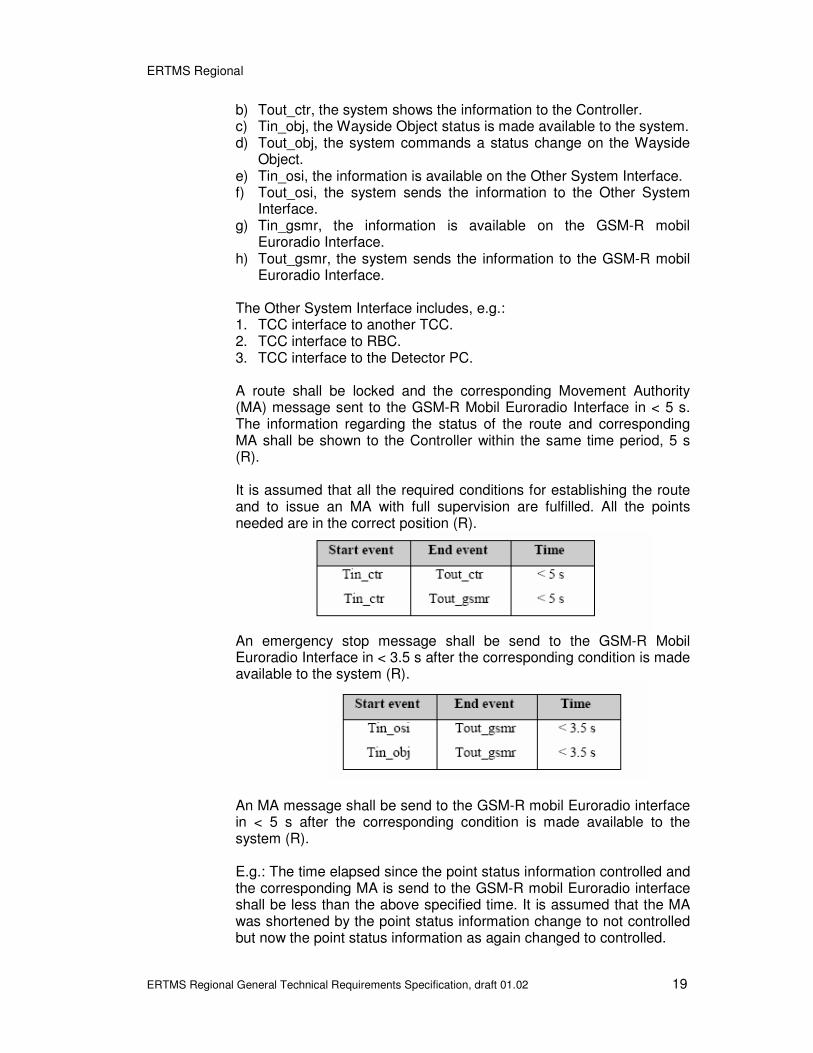
Euroradio Interface. The Other System Interface includes, e.g.: 1. TCC interface to another TCC. 2. TCC interface to RBC. 3. TCC interface to the Detector PC. A route shall be locked and the corresponding Movement Authority (MA) message sent to the GSM-R Mobil Euroradio Interface in < 5 s. The information regarding the status of the route and corresponding MA shall be shown to the Controller within the same time period, 5 s (R). It is assumed that all the required conditions for establishing the route and to issue an MA with full supervision are fulfilled. All the points needed are in the correct position (R).
An emergency stop message shall be send to the GSM-R Mobil Euroradio Interface in < 3.5 s after the corresponding condition is made available to the system (R).
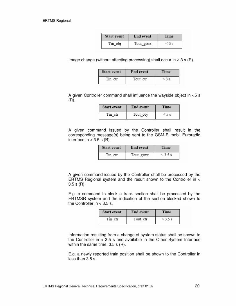
An MA message shall be send to the GSM-R mobil Euroradio interface in < 5 s after the corresponding condition is made available to the system (R). E.g.: The time elapsed since the point status information controlled and the corresponding MA is send to the GSM-R mobil Euroradio interface shall be less than the above specified time. It is assumed that the MA was shortened by the point status information change to not controlled but now the point status information as again changed to controlled.
ERTMS Regional
ERTMS Regional General Technical Requirements Specification, draft 01.02 20
Image change (without affecting processing) shall occur in < 3 s (R).
A given Controller command shall influence the wayside object in <5 s (R).
A given command issued by the Controller shall result in the corresponding message(s) being sent to the GSM-R mobil Euroradio interface in < 3.5 s (R).
A given command issued by the Controller shall be processed by the ERTMS Regional system and the result shown to the Controller in < 3.5 s (R). E.g. a command to block a track section shall be processed by the ERTMSR system and the indication of the section blocked shown to the Controller in < 3.5 s.
Information resulting from a change of system status shall be shown to the Controller in < 3.5 s and available in the Other System Interface within the same time, 3.5 s (R). E.g. a newly reported train position shall be shown to the Controller in less than 3.5 s.

ERTMS Regional
ERTMS Regional General Technical Requirements Specification, draft 01.02 21
The Level Crossing strike-in shall be released by the system in < 2 s after the Level Crossing’s track section free status is made available to the system. It is assumed that all the remaining conditions for releasing the Level Crossing strike-in are fulfilled (R).
The ERTMS Regional system shall handle trains running up to 200 km/h (R).
4.4 Capacity
One TCC shall be capable of handling no less than (R): a) 30 registered traction units b) 30 simultaneous movements c) 200 Objects (interface EG – interface EM)
5. Environment
5.1 Introduction
This section specifies the environmental requirements for the ERTMS Regional system. Requirements are specified below for: 1. Environmental conditions 1.1. Operational 1.2. Transport 1.3. Storage 2. Environmental pollution/contamination 3. Electromagnetic compatibility 4. CE certificate
5.2 Environmental conditions

ERTMS Regional
ERTMS Regional General Technical Requirements Specification, draft 01.02 22
5.2.1 Operational
The equipment shall have full functionality within the requirements specified in the table below, according to the location where the equipment is installed.

ERTMS Regional
ERTMS Regional General Technical Requirements Specification, draft 01.02 23
Table 18 – Operational environmental requirements.
The equipment shall not be affected when subjected to any form of precipitation. In this respect, considerations shall be given to (but not limited to) the following (R): a) The effects of snow, ice and hail penetrating equipment housings. b) The effects of snow melting and freezing again. The Eurobalise shall comply with SUBSET-036, chapter 5.7 “Specific Environmental Conditions for Balises” of the ERTMS/ETCS class 1 specs (R). All the requirements referring to EN 50125-3 are as defined in the operational environmental requirements. The Eurobalise shall be of the type “Class A”, according to SUBSET-036, version 2.2.1, chapter 5.7.9 “Debris” of the ERTMS/ETCS class 1 specs (R).

ERTMS Regional
ERTMS Regional General Technical Requirements Specification, draft 01.02 24
5.2.2 Transport
Full functionality is not required during transport, but the equipment shall not be damaged temporarily or permanently if the specified conditions below are kept within (R). If the equipment is exposed to environmental conditions outside specified in the requirements during transport, malfunctions that may occur shall not affect the overall safety of the ERTMS Regional system (R). During transport, the equipment shall not be damaged by exposure to ambient temperatures in the following range (R): Tmin=-40 ºC Tmax=+85 ºC For all other environmental requirements, the specified operational environmental requirements listed in the respective chapter shall apply during transport (R).
5.2.3 Storage
Full functionality is not required during storage, but the equipment shall not be damaged temporarily or permanently if the specified conditions below are kept within (R). If the equipment is exposed to environmental conditions outside specified requirements during storage, malfunctions that may occur shall not affect the overall safety of the ERTMS Regional system (R). During storage, the equipment shall not be damaged by exposure to ambient temperatures in the following range (R): Tmin=-40 ºC Tmax=+85 ºC For all other environmental requirements, the specified operational environmental requirements listed in the respective chapter shall apply during storage (R).
5.3 Environmental pollution/contamination
Banverket considers products in a life cycle perspective. This implies: a) Products that under theirs life cycles are environment friendly, producing less waste, less environmental stress and using less energy resources. b) Products that have a long and/or optimal life period. c) Products that can be reused or recycled. d) Products that at the end of theirs life cycles give origin to less environmental stress.

ERTMS Regional
ERTMS Regional General Technical Requirements Specification, draft 01.02 25
The following points give examples of product’s characteristics that Banverket considers as environmentally positive: a) Low energy consumption. b) No use of heavy metals like lead, cadmium or mercury. c) No use of CFC or HCFC in the products or manufacturing process. d) No brominated flame retardants. e) Manufactured without solvent based coating technology. f) Labelling of incoming material to facilitate an environmentally
correct disposal. g) Recycable products. The contractor shall show environmental aspects according to the above or other environmentally positive aspects of the products (R). The contractor shall specially indicate if (R): a) The products have an environment mark (SIS environment mark). b) The products include an environment dangerous mark. Check KIFS
1994:12. c) The product under its life time produces environment dangerous
waste. What is considered non environment dangerous waste is described in “Avfallsförordning (2001:1063)”, that is part of “Miljöbalen (SFS 1998:808).
d) Supplied display screens (CRT and LCD) are free from cadmium and its compounds.
e) Plastic parts weighing more than 25 grams does not contain actively added lead.
f) Plastic in casings and chassis (parts weighing more than 25 grams) does not contain additives of PBB, PBDE and chlorinated paraffin.
g) The product meets the energy saving requirements in accordance with ENERGY STAR (for information about Energy Star see:www.energystar.gov).
h) The product does not contain batteries classified as environmentally harmful in the Commission’s Directive 91/157/EEC.
i) The product has an environmental declaration in accordance with ISO 14020:2000, 14021:1999 or 14024:1999.
5.4 EMC
The facilities/equipment shall comply with Banverket standard BVS 560.1101 (R).
5.5 CE certificate
The equipment shall have a CE certificate (R).

ERTMS Regional
ERTMS Regional General Technical Requirements Specification, draft 01.02 26
6. Design
6.1 Spare Capacity
The ERTMS Regional system shall have at least 20% of spare capacity regarding the memory size and CPU power (R).
6.2 Date and Time
All subsystems included in ERTMS Regional shall have synchronised date and time (R).
6.3 Grounding
Equipment shall comply with BVF 510, “Jordning och skärmning i Banverkets anläggningar”, chapter 12 (R).
6.4 Cables and Network
The Contractor shall for the ERTMS Regional system use approved cables, as listed in this section (R). {National description to be included. Example from the Swedish Project in annex xx } If the Contractor proposes other cables than those approved according to the above list, then the Contractor shall submit a description of the suggested cables to the Purchaser for assessment and approval prior to the decision of making use of them in the design (R). When/if the Contractor makes use of an IP based network for internal or external communication, then the Purchasers IP shall be used when available (R).
6.5 Qualitative requirements
To the greatest extent possible, the basis for the design and the architecture of the ERTMS Regional system shall apply the following standard systems and objectives: a) Portability of application development tools. b) Portability of applications. c) IP protocol. d) Standard communication protocols. e) Standard hardware platforms. f) Standard operating system software. g) Standard user interface. h) Standard network management. i) Standard application protocols.

ERTMS Regional
ERTMS Regional General Technical Requirements Specification, draft 01.02 27
The purpose of the Qualitative Requirements below is to address the design toward solutions which facilitate maintenance, future modifications, use, interchangeability and compatibility. Accessibility: The equipment shall be designed in such a way that all its parts and related connections permit inspection, repair, revision and replacement, taking into account the dimensions of the required equipment (R). Dismounting: During a maintenance action, it shall be possible to disassemble and to remove any item without being compelled to involve other items not directly related to the specific maintenance action (R). Interchangeability: The system shall be designed in such a way that any item can be removed and another installed in its place without affecting any equipment characteristics. The replacement shall be compatible with respect to physical, electrical, communication and information interfaces (R). Modularity: The design of the ERTMS Regional system shall have a modular approach, to support a wide range of different site applications (R). Adaptability: The ERTMS Regional system hardware and software shall be adaptable to changes in functional requirements and interfaces (R). Compatibility: The system shall be designed to facilitate forward and backward compatibility for both hardware and software. This in order to facilitate upgrading (R).

ERTMS Regional
ERTMS Regional General Technical Requirements Specification, draft 01.02 28
7. References

ERTMS Regional
ERTMS Regional General Technical Requirements Specification, draft 01.02 29
8. Annex A
{List to be updated to latest version of CCS TSI Annex1 at the time of tendering}

ERTMS Regional
ERTMS Regional General Technical Requirements Specification, draft 01.02 30
9. Annex B
GRS from the Swedish Project