electric current -...
TRANSCRIPT

Electric CurrentElectric current is the rate of flow of charge through some region of spaceThe SI unit of current is the ampere (A)
1 A = 1 C / sThe symbol for electric current is I
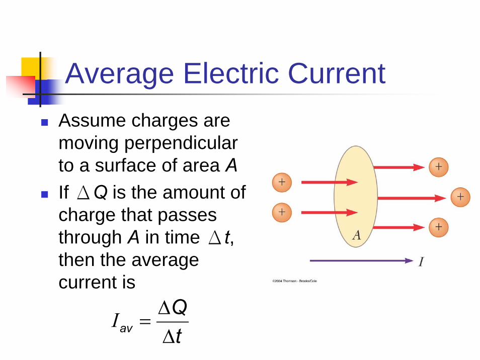
Average Electric CurrentAssume charges are moving perpendicular to a surface of area AIf ΔQ is the amount of charge that passes through A in time Δt, then the average current is
avQt
Δ=
ΔI

Instantaneous Electric CurrentIf the rate at which the charge flows varies with time, the instantaneous current, I, can be found
I dQdt
=
Direction of CurrentThe charges passing through the area could be positive or negative or bothIt is conventional to assign to the current the same direction as the flow of positive chargesThe direction of current flow is opposite the direction of the flow of electronsIt is common to refer to any moving charge as a charge carrier

Current and Drift SpeedCharged particles move through a conductor of cross-sectional area An is the number of charge carriers per unit volumenA Δx is the total number of charge carriers
Current and Drift Speed, contThe total charge is the number of carriers times the charge per carrier, q
ΔQ = (nA Δx)qThe drift speed, vd, is the speed at which the carriers move
vd = Δx / ΔtRewritten: ΔQ = (nAvd Δt)qFinally, current, Iav = ΔQ/Δt = nqvdA

Charge Carrier Motion in a Conductor
The zigzag black line represents the motion of a charge carrier in a conductor
The net drift speed is small
The sharp changes in direction are due to collisionsThe net motion of electrons is opposite the direction of the electric field
Motion of Charge Carriers, cont.
In spite of all the collisions, the charge carriers slowly move along the conductor with a drift velocity, vd
Changes in the electric field that drives the free electrons travel through the conductor with a speed near that of light
This is why the effect of flipping a switch is effectively instantaneous

Electric current
Direction of currentGmotion direction of positive chargeI⊕E+ −
Current density•I
A
2 ( )I AJ mA= I J dA= ⋅∫
rrˆdA dAn=
r
( )I AJ mL=
L
I
0 0
( ) ( )
, Q t
dq CI A Ampsdt
dq Idt dq Idt Q It
= =
= = ⇒ =∫ ∫

Consider the conductor shown in the figure. It is connected to a battery (not shown) and thus charges move through the conductor.Consider one of the cross sections through the conductor( aa or bb or′ ′
Current = rate at which charge
cc ).
The electric current is
Current SI Unit:
de
C/s
flo
kn
w
own as the "Amp
fined as
s
er
:
e"
dqid
it
=
′
(26 - 3)
dqidt
=

i
+ q
conductor
vr
i
- q
conductor
vr
An electric current is represented by an arrow which has the same direction as the charge velocity.The sense of the current arrow is defined as follows:
If the current is due to the motion of p1. osit charges the current arrow is to the charge velocity
If the current is due to the motion of charges the current arrow is to the charge velocity
vparallel
2.antipara
negativellel
ive
r
.vr
(26 - 3)
Current direction :

i
- q
conductor
vr A
Jr
Current density is a vector that is defined as
follows: Its magnitude
The direction of is the same as that of the current. The current through a conductor of
cros
iJA
J
=
r
2SI unit for J: A/m
s sectional area is given by the equation:, if the current density is constant.
If is not constant then: .
i JA
i J dA
A
J
=
= ⋅∫rr r
i
+ q
conductor
vr A
Jr
iJA
=
(26 - 4)
Current density

1
We note that even though the current density is a vector the electric current is not. This is illustrated in the figure to the left. An incoming current branches atpoint a into two currents,
oii 2
1 2
, and . Current This equation expresses the conservation of charge at point a. Please note that we have not used vector addition
.
oi i ii
= +
(26 - 4)
i
- q
conductor
vr A
Jr
i
+ q
conductor
vr A
Jr
iJA
=

When a current flows through a conductor the electric field causes the charges to move with a constant drift speed . This drift speedis superimposed on the random motion of the charges.
dv
dJ nev=r r
dJ nv e=
(26 - 5)
Drift speed

- : electron Carrier
: electric hole ⎧⎨ +⎩
number of carriersSteady current : , ( ) , : ,volume
QI Q AL qt
η η= =
A
v
L
motionrandom
q
1 .d avL L I JI A q v vt t A q q
ηη η
= ⇒ = = = =
charge: charge density ( )volume
.d dJ qv vρ
η ρ= =v v v
Drift speed•
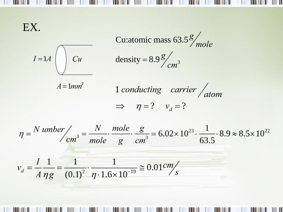
EX.
CuAI 1=
21mmA= 1
? ?d
conducting carrier atomvη⇒ = =
23 223 3
16.02 10 8.9 8.5 1063.5
N mole gN umbercm mole g cm
η = = ⋅ ⋅ = × ⋅ ⋅ ≈ ×
2 19
1 1 1 0.01(0.1) 1.6 10d
I cmv sA gη η −= = ⋅ ≅⋅ ×
3
Cu:atomic mass 63.5
density 8.9
gmole
gcm=

Resistance•
can be viewed as the result of the carrier under an acceleration in an average time interval . (average time between two collisions)
d
av
v
t
A
L
V
E
q
2
e
d
av av
F qE mavma m m JE
q q t q tη
= =
= = = ⋅
avt
avd vv =
slpoe a=

0 (1 ) T : temperature, : temperature coefficient of .
Tρ ρ αα ρ
= + Δ
0 (1 ).LR R R TA
ρ α= ⇒ = +
2
1 Let resistivity conductivity
, .
av
mq t
JE J J E
ρ ση ρ
ρ σσ
= =
⇒ = = =r r
resistance ( ohm, ) .
IEL JL V LA
LLet R V IRA
ρ ρ
ρ
= ⇒ =
= Ω ⇒ =

Er
+ -
i
V
Er Unlike the electrostatic case, the electric field
in the conductor of the figure is not zero. We define as resistivity of the conductor
the ratio . In vector for m
V/m
: EJ
E Jρ
ρ
ρ==
SI unit for ρ :
r r
2
The conductivity is defined as:
Using the previous equation takes
V m
the for
1
m:
A/m A
m
J Eσ
σσρ
ρ
= = Ω ⋅
=
=
r rLRA
ρ=
E Jρ=r r
J Eσ=r r
(26 -7)
Resistivity

Er
+ -
i
V
Er Consider the conductor shown in the
figure above. The electric field inside the
conductor .
The current density
We substitute and into equation
and get:
/ /
VEL
iJA
E JEJV L V A AR Ri A i L L
ρ
ρ
=
=
=
= = = → =LA
ρLRA
ρ=
E Jρ=r r
J Eσ=r r
(26 -7)

In the figure we plot the resistivity of copper as function of temperature . The dependence of on is almost linear. Similar dependence is observed in many conductors.
T Tρ
ρ
( )o o oT Tρ ρ υ α− = −
(26 -8)
Variation of resistivity with temperature

A resistor was defined as a conductor whose resistance does not change with the voltage applied across it. In fig.b we plot the current through a resistor as function of . The plot
V
i V
Ohm's Law :
(known as " - curve" ) is a straight line that passes through the origin. Such a conductor is said to be " " and it obeys Ohm's law that stateThe current through a conductor is pr
soport ona
:ii
i VOhmic
l to the voltage applied across it.
V
(26 - 9)

Not all conductors abey Ohm's law (these are known as " " ) An example is given in fig.c where we plot versus for a semiconductor diode.The ratio / (and thus the resistance ) is not
i V
V i R
non - Ohmic
constant. As a matter of fact the diode does not conduct for negative voltage values.
Ohm's "law" is in reality a definition of Ohmic conductors (defined as the conductors that obey Ohm's laNote :
w)
(26 - 9)
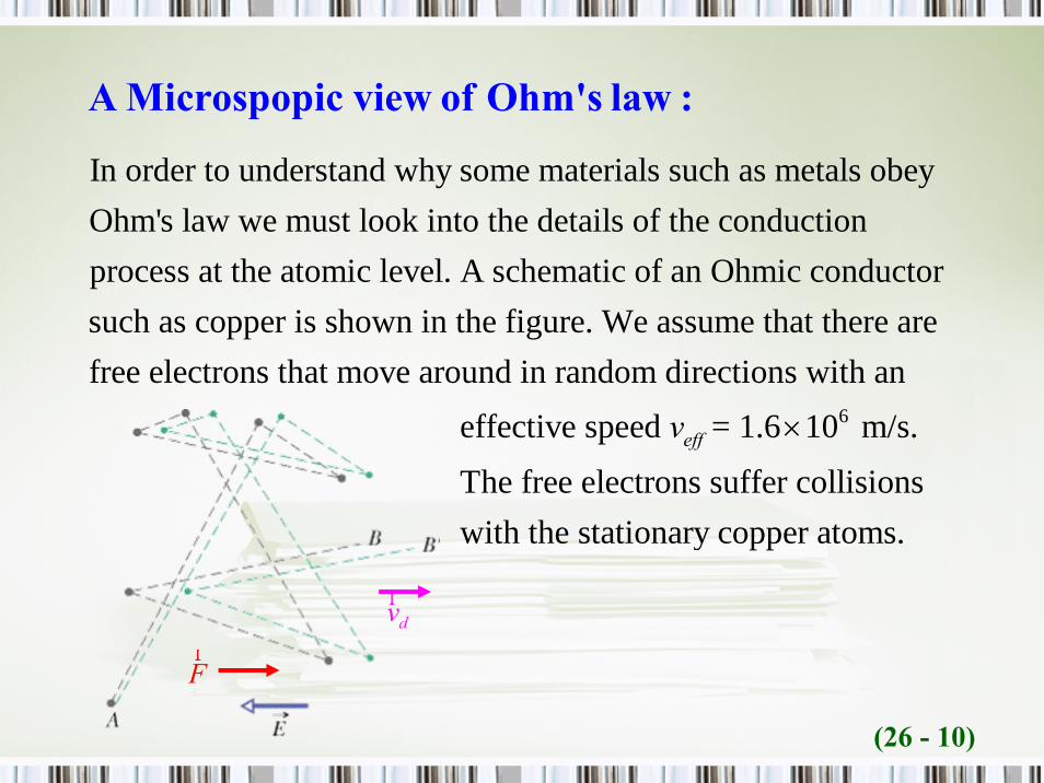
In order to understand why some materials such as metals obey Ohm's law we must look into the details of the conduction process at the atomic level. A schematic of an Ohmic conductor such as copper is
6
shown in the figure. We assume that there are free electrons that move around in random directions with an effective speed = 1.6 10 m/s.
effv ×
The free electrons suffer collisions with the stationary copper atoms.
(26 - 10)
Fr
dvr
A Microspopic view of Ohm's law :

A schematic of a free electron path is shown in the figure in the figure using the dashed gray line. The electron starts at point A
and ends at point B. We now assume that an electric field is appl
Er
ied. The new electron path is indicated by the dashed green line. Under the action of the electric force the electron acquires a small drift speed . The electron drifts to the right and ends at point B .
dv′
(26 - 10)
Fr
dvr

Fr
dvr
Consider the motion of one of the free electrons. We assume that the average time between collisions with the copper atoms is equal to . The electic field exerts a force on the electron,
resu
F eEτ =
lting in an acceleration .
The drift speed is given by the equation:
( ) d
F eEam m
eEv amττ
= =
= = eqs.1
(26 - 11)

Fr
dvr
2
2
We can also get from the equation: ( )
If we compare equations 1 and 2 we get:
. If we compare the last equation with:
we conclude t tha :
d d d
d
Jv J nev vne
J eE mv E Jne m
mne
ne
E J
ττ
ρ ρτ
= → =
⎛ ⎞= = → = ⎜ ⎟⎠
= =
⎝
eqs.2
This is a statement of Ohm's law
(the resistance of the conductor does not depend on voltage and
thus ) This is because , , and are constants. The time can also be considered be
Em n eτ
independent of since the drift spees is so much smaller than .
d
eff
E vv
(26 - 11)
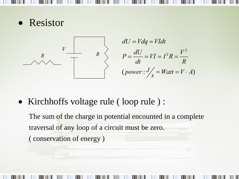
Resistor•
R RV
The sum of the charge in potential encounted in a complete traversal of any loop of a circuit must be zero. ( conservation of energy )
22
( : )
dU Vdq VIdtdU VP VI I Rdt R
Jpower Watt V As
= =
= = = =
= = ⋅
Kirchhoffs voltage rule ( loop rule ) :•

ResistivityValues

ResistorsMost circuits use elements called resistorsResistors are used to control the current level in parts of the circuitResistors can be composite or wire-wound
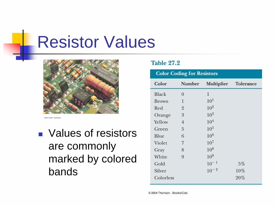
Resistor Values
Values of resistors are commonly marked by colored bands

Resistance of a Cable, Example
Assume the silicon between the conductors to be concentric elements of thickness drThe resistance of the hollow cylinder of silicon is
2ρdR drπrL
=

Resistance of a Cable, Example, cont.
The total resistance across the entire thickness is
This is the radial resistance of the cableThis is fairly high, which is desirable since you want the current to flow along the cable and not radially out of it
2ln
b
a
ρ bR dRπL a
⎛ ⎞= = ⎜ ⎟⎝ ⎠∫

Conduction Model, finalUsing Ohm’s Law, expressions for the conductivity and resistivity of a conductor can be found:
Note, the conductivity and the resistivity do not depend on the strength of the fieldThe average time is also related to the free mean path: τ = ℓ/vav
2
21 e
e
nq τ mσ ρm σ nq τ
= = =
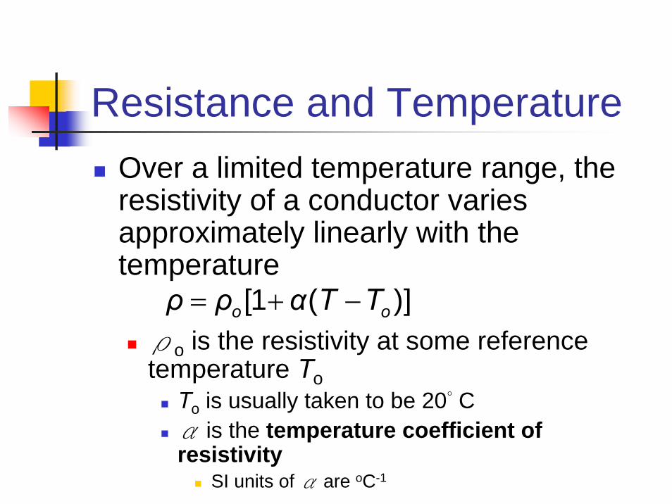
Resistance and TemperatureOver a limited temperature range, the resistivity of a conductor varies approximately linearly with the temperature
ρo is the resistivity at some reference temperature To
To is usually taken to be 20° Cα is the temperature coefficient of resistivity
SI units of α are oC-1
[1 ( )]o oρ ρ α T T= + −

Temperature Variation of Resistance
Since the resistance of a conductor with uniform cross sectional area is proportional to the resistivity, you can find the effect of temperature on resistance
R = Ro[1 + α(T - To)]
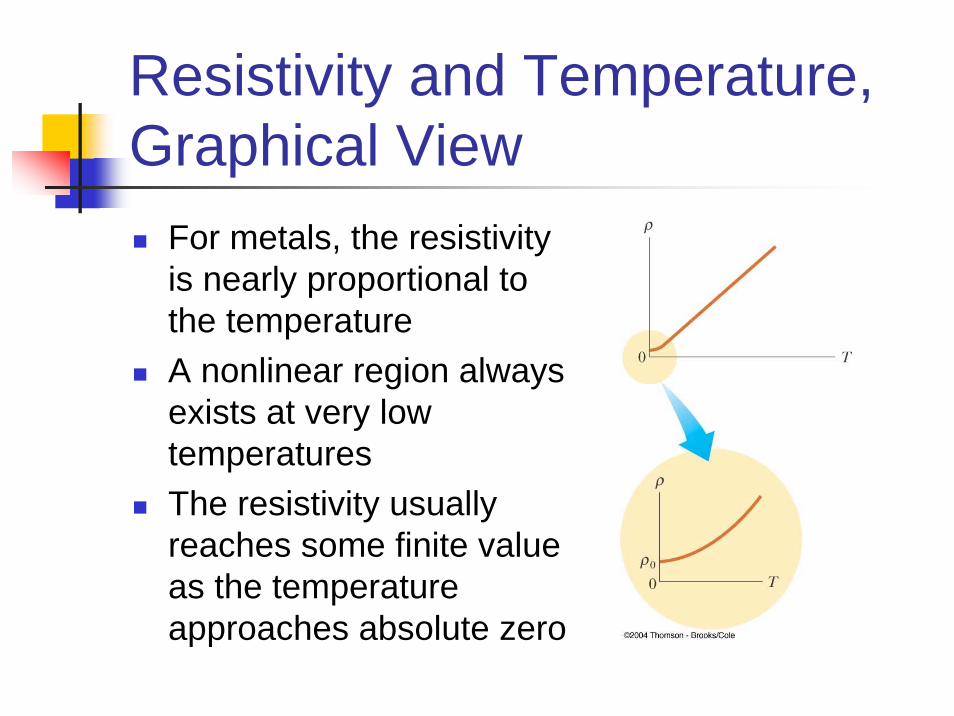
Resistivity and Temperature, Graphical View
For metals, the resistivity is nearly proportional to the temperatureA nonlinear region always exists at very low temperaturesThe resistivity usually reaches some finite value as the temperature approaches absolute zero

Residual ResistivityThe residual resistivity near absolute zero is caused primarily by the collisions of electrons with impurities and imperfections in the metalHigh temperature resistivity is predominantly characterized by collisions between the electrons and the metal atoms
This is the linear range on the graph
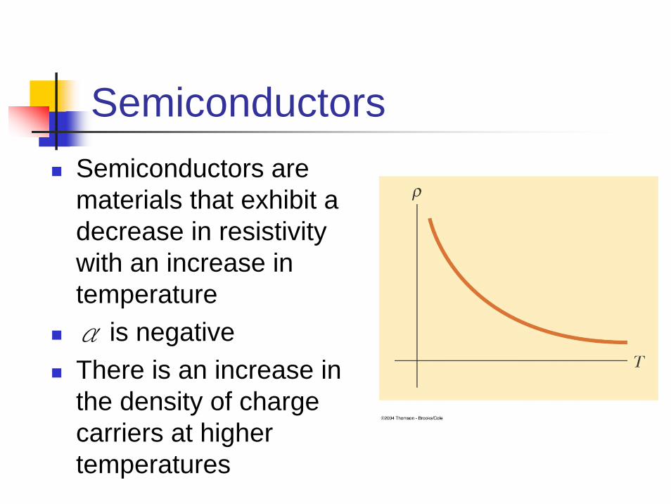
SemiconductorsSemiconductors are materials that exhibit a decrease in resistivity with an increase in temperatureα is negativeThere is an increase in the density of charge carriers at higher temperatures

SuperconductorsA class of materials and compounds whose resistances fall to virtually zero below a certain temperature, TC
TC is called the critical temperature
The graph is the same as a normal metal above TC, but suddenly drops to zero at TC

Superconductors, contThe value of TC is sensitive to:
chemical compositionpressuremolecular structure
Once a current is set up in a superconductor, it persists without any applied voltage
Since R = 0
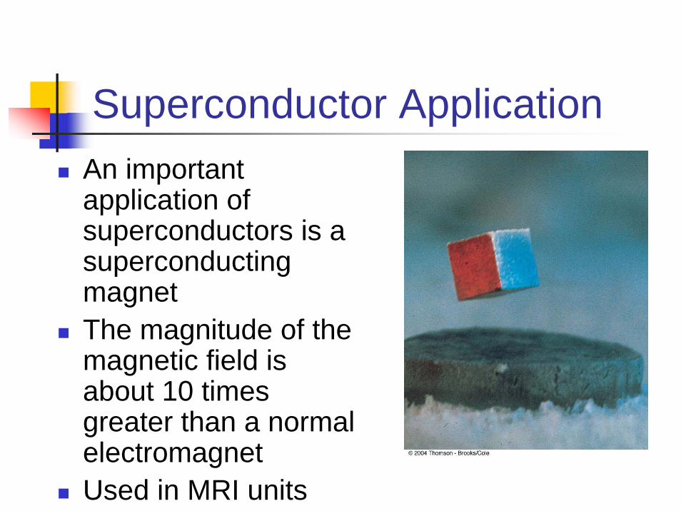
Superconductor ApplicationAn important application of superconductors is a superconducting magnetThe magnitude of the magnetic field is about 10 times greater than a normal electromagnetUsed in MRI units

Electrical PowerAssume a circuit as shownAs a charge moves from a to b, the electric potential energy of the system increases by QΔV
The chemical energy in the battery must decrease by this same amount

Electric Power, finalThe power is given by the equation:
Applying Ohm’s Law, alternative expressions can be found:
Units: I is in A, R is in Ω, V is in V, and is in W
I V℘= Δ
22 I I VV R
R℘= Δ = =
℘

Electric Power TransmissionReal power lines have resistancePower companies transmit electricity at high voltages and low currents to minimize power losses