effect of steel slag and portland cement in the rate of ... of steel slag.pdf · slag (bos) and...
TRANSCRIPT
Effect of steel slag and Portland cement in the rate of hydration and strength of blast furnace slag pastes Lizarazo-Marriaga, J. , Claisse, P.A. and Ganjian, E. Author post-print (accepted) deposited in CURVE November 2012 Original citation & hyperlink: Lizarazo-Marriaga, J. , Claisse, P.A. and Ganjian, E. (2011) Effect of steel slag and Portland cement in the rate of hydration and strength of blast furnace slag pastes. Journal of Materials in Civil Engineering, volume 23 (2): 153-160. http://dx.doi.org/10.1061/(ASCE)MT.1943-5533.0000149 Copyright © and Moral Rights are retained by the author(s) and/ or other copyright owners. A copy can be downloaded for personal non-commercial research or study, without prior permission or charge. This item cannot be reproduced or quoted extensively from without first obtaining permission in writing from the copyright holder(s). The content must not be changed in any way or sold commercially in any format or medium without the formal permission of the copyright holders. This document is the author’s post-print version, incorporating any revisions agreed during the peer-review process. Some differences between the published version and this version may remain and you are advised to consult the published version if you wish to cite from it.
CURVE is the Institutional Repository for Coventry University http://curve.coventry.ac.uk/open
1
Effect of steel slag and Portland cement in the rate of hydration and strength of blast furnace slag pastes
Juan Lizarazo-Marriagaa,b, Peter Claisseb, Eshmaiel Ganjianb
a Departamento de Ingeniería Civil, Universidad Nacional, Bogotá, Colombia.
b Construction Materials Applied Research Group, Coventry University CV1 5FB, UK.
Abstract
This paper presents an experimental study of the influence of Steel Basic Oxygen
Slag (BOS) and Portland cement (OPC) on the compressive strength and the
hydration mechanisms of blended Grounded Granulated Blast Furnace Slag (GGBS)
pastes. The compressive strength, the mineralogical changes due to hydration, the
setting times, the alkalinity of the raw materials and the pore solution, and the volume
stability were measured on binary and ternary mixes. It is concluded that the steel
slag can be used as an activator of GGBS and the optimum composition of those
materials was determined with a proposed parameter called “slag index”. The
properties measured in blended OPC-GGBS-BOS mixes showed encouraging
results to be used industrially. The mechanisms of hydration of the blended slag
mixes are discussed and a hydration model of the blended system GGBS-BOS is
proposed.
1. Introduction Slag is a by-product of the metallurgical industry where metals such as iron, copper,
lead, or aluminium, are purified or transformed. Depending on its chemical and
physical properties the slag can be used in the construction industry as aggregate in
granular bases, asphalt mixes, and concrete mixes; as cement replacement, or in
embankments or fill applications. Worldwide the most commonly used slag is
Granulated Blast Furnace slag (GGBS), however, efforts are being made to use
other types of slag that are available in large quantities and, in the same way as
GGBS, could have some potential cementitious properties.
2
GGBS slag is a non metallic material resulting from the combination of the calcium
and magnesium in calcareous stones with the aluminates and silicates in iron ore.
The chemical and mineralogical composition of GGBS depends on the
characteristics of the metallurgical process and materials; however, the principal
compounds are CaO, SiO, Al2O, and MgO that are present in most hydraulic binders.
Compared to OPC, slag has a higher silica content and lower calcium content, and
contains low quantities of ferric oxide. For a typical sample of GGBS the glass
content is around 85-90%, and with this, the basicity is considered the factor
governing its hydraulicity. The more basic the slag, the greater its hydraulic reactivity
in the presence of alkaline activators (Detwiler et al. 1996). According to Tailing and
Krivenko (1997), the hydration of slag involves complex chemical and physical
reactions such as adsorption, ion exchange, dissolution, and hydrolysis. When
contact with water, the slag grains develop some external insoluble thin layers
composed of silica and an alkali earth hydrosilicate preventing further reactions on
their surface. Under highly alkali environments, the formation of this external film is
inhibited and no retardation of the hydration process occurs.
GGBS as a binder can be used in different ways. Blended cements of GGBS and
ordinary Portland cement (OPC) have been used for more than 100 years and are
covered by international standards (ASTM-C595 2008). The combination of GGBS
with OPC and pozzolans is reported by the American Concrete Institute committee
233 (ACI-233 2003). GGBS-alkali activated binder systems are used extensively in
Eastern Europe (Tailing and Krivenko 1997), and the activation of slags with sulphate
minerals have been used for more than 50 years in Europe (Matschei et al. 2005).
Steel slag is a by-product of the transformation of iron to steel. Pig iron is collected
from the blast furnace, transferred to the steel plant and charged into a steelmaking
vessel, typically a basic oxygen furnace (BOF). During the conversion, pig iron and
scrap are melted and fluxes of lime or dolomite are mixed into the furnace. In order to
take out the impurities of the melting steel, high pressure oxygen is injected removing
undesirable contaminants, which are combined with the lime or dolomite to produce
the Basic Oxygen Steel (BOS)_slag. After refining, the liquid steel is poured into a
ladle to continue the metallurgical process, while the slag is collected with other
processes.
3
Steel slag has not been extensively used as a cement replacement because
theoretically it has some disadvantages:
• A highly variable mineralogical composition.
• The low content of reactive calcium silicate compounds gives to the steel slag
poor cementing properties.
• The high content of free calcium and magnesium oxides cause volume
expansion problems.
• Steel slag has higher density than other binders.
• The possibility of leaching of metals such as chromium and molybdenum has
been an environmental obstacle.
Despite the problems associated with steel slag, it has many possibilities for use in
the cement and concrete industry. In China, for example, it has been commercialized
for long time in a cement that contains 35% Portland clinker, 5% gypsum, 30% steel
furnace slag, and 30% blast furnace slag (Shi 2004). Steel slag could be used in
cement production in different ways: it can be used as raw material in the clinker
production as was reported by Monshi and Asgarani (1999) and Tsakiridis et al.
(2008), or can be blended in the cement as an mineral admixture (Xuequan et al.
1999; Rai et al. 2002; AkIn Altun and Yilmaz 2002; Kourounis et al. 2007) or
aggregate, or just as a filler (Qasrawi et al. 2009; Sajkata et al. 2007).
In contrast to GGBS where the calcium and magnesium oxides combine and form
non expansive compounds, in the metallurgical process of steel slag calcium and
magnesium oxides are left free. Free lime expansion could occur due to the increase
of volume caused by the hydration of lime to form calcium hydroxide. When steel
slag is used in road construction it is a common practice to let it undergo a
weathering process. This consists of leaving the slag in stockpiles exposed to the
weather for a specific period of time in order to reduce its content of unhydrated lime.
Bin et al. (1992) reported a GGBS-steel slag cement which was alkali activated
through the use of 5% of sodium silicate. In the same way, in a recent study Mahieux
et al. (2009) conclude that weathered BOS slag seems to have little hydraulic activity
4
and apparently no pozzolanic properties; however, combining BOS slag with GGBS
and small amounts of a catalyst (GGBS:52.5%, BOS:42.5%, catalyst:5%) gives very
good results in terms of compressive strength. The activation of GGBS was attributed
in part to the lime present in the BOS slag and in part due to the catalyst. In addition,
it was found that the GGBS-BOS-catalyst cement did not presented expansion
problems
The principal aim of the present work was to investigate the influence of steel slag
and Portland cement on the evolution of the compressive strength and their effects
on the hydration mechanisms of blended blast furnace slag pastes. For this, the
mineralogical changes due to hydration, the setting times, the alkalinity of the raw
materials and the pore solution, and the volume stability were measured on binary
and ternary mixes.
2. Materials
The materials used in this research were obtained from different sources. A summary
of them is presented below.
• A commercial Ordinary Portland cement (OPC) classified as CEM-1
according to British Standard BS EN 197-1 “Composition, specifications and
conformity criteria for common cements”.
• A Ground Granulated blast furnace slag (GGBS) obtained from Civil and
Marine, a part of Hanson UK. The material was marketed under the standard
BS 6699 “Specification for ground granulated blast furnace slag for use with
Portland cement”.
• A Basic Oxygen slag (BOS) obtained from Tarmac UK, from Corus
Scuntrorpe plant UK. It was ground and sieved through a 600 micron sieve
before being used. Because the time between the grinding and use was more
than one year, the slag is considered to be weathered.
5
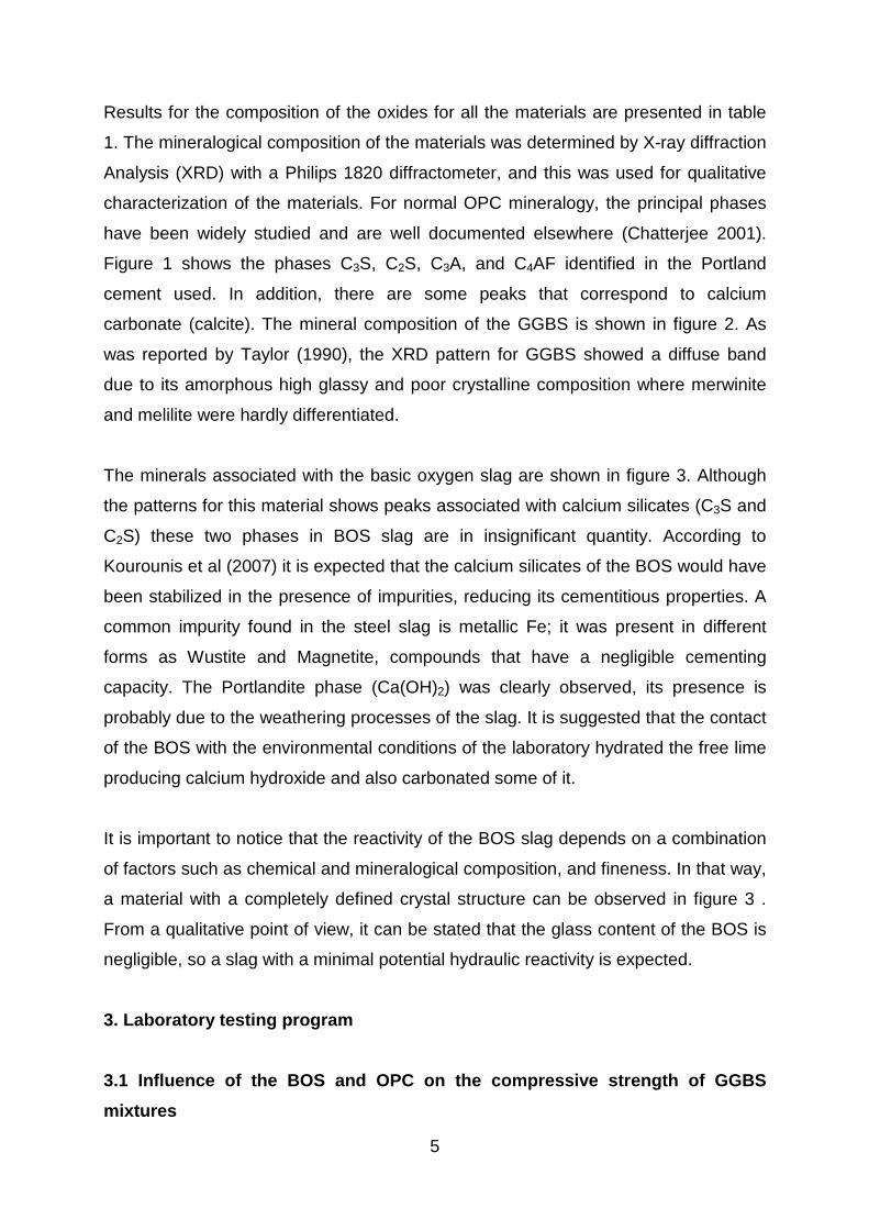
Results for the composition of the oxides for all the materials are presented in table
1. The mineralogical composition of the materials was determined by X-ray diffraction
Analysis (XRD) with a Philips 1820 diffractometer, and this was used for qualitative
characterization of the materials. For normal OPC mineralogy, the principal phases
have been widely studied and are well documented elsewhere (Chatterjee 2001).
Figure 1 shows the phases C3S, C2S, C3A, and C4AF identified in the Portland
cement used. In addition, there are some peaks that correspond to calcium
carbonate (calcite). The mineral composition of the GGBS is shown in figure 2. As
was reported by Taylor (1990), the XRD pattern for GGBS showed a diffuse band
due to its amorphous high glassy and poor crystalline composition where merwinite
and melilite were hardly differentiated.
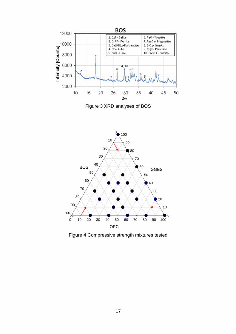
The minerals associated with the basic oxygen slag are shown in figure 3. Although
the patterns for this material shows peaks associated with calcium silicates (C3S and
C2S) these two phases in BOS slag are in insignificant quantity. According to
Kourounis et al (2007) it is expected that the calcium silicates of the BOS would have
been stabilized in the presence of impurities, reducing its cementitious properties. A
common impurity found in the steel slag is metallic Fe; it was present in different
forms as Wustite and Magnetite, compounds that have a negligible cementing
capacity. The Portlandite phase (Ca(OH)2) was clearly observed, its presence is
probably due to the weathering processes of the slag. It is suggested that the contact
of the BOS with the environmental conditions of the laboratory hydrated the free lime
producing calcium hydroxide and also carbonated some of it.
It is important to notice that the reactivity of the BOS slag depends on a combination
of factors such as chemical and mineralogical composition, and fineness. In that way,
a material with a completely defined crystal structure can be observed in figure 3 .
From a qualitative point of view, it can be stated that the glass content of the BOS is
negligible, so a slag with a minimal potential hydraulic reactivity is expected.
3. Laboratory testing program 3.1 Influence of the BOS and OPC on the compressive strength of GGBS mixtures
6
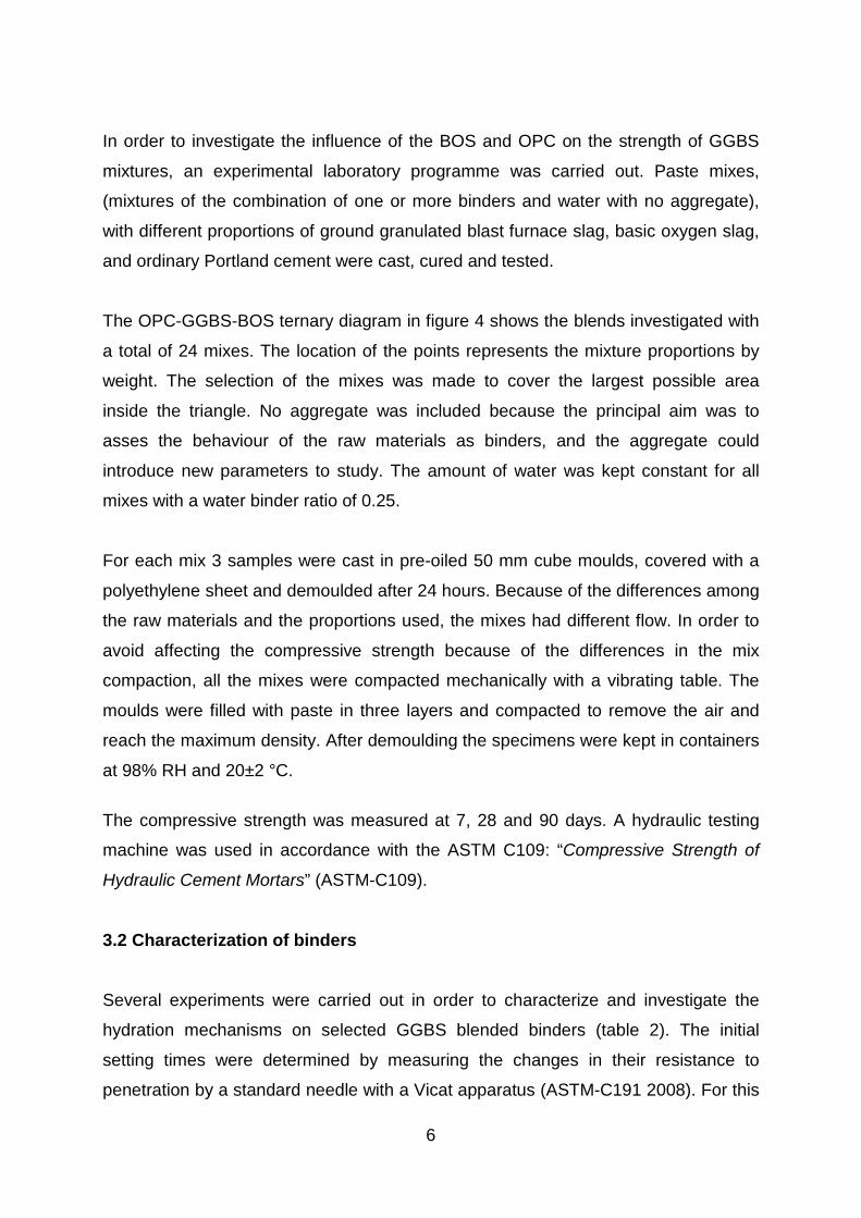
In order to investigate the influence of the BOS and OPC on the strength of GGBS
mixtures, an experimental laboratory programme was carried out. Paste mixes,
(mixtures of the combination of one or more binders and water with no aggregate),
with different proportions of ground granulated blast furnace slag, basic oxygen slag,
and ordinary Portland cement were cast, cured and tested.
The OPC-GGBS-BOS ternary diagram in figure 4 shows the blends investigated with
a total of 24 mixes. The location of the points represents the mixture proportions by
weight. The selection of the mixes was made to cover the largest possible area
inside the triangle. No aggregate was included because the principal aim was to
asses the behaviour of the raw materials as binders, and the aggregate could
introduce new parameters to study. The amount of water was kept constant for all
mixes with a water binder ratio of 0.25.
For each mix 3 samples were cast in pre-oiled 50 mm cube moulds, covered with a
polyethylene sheet and demoulded after 24 hours. Because of the differences among
the raw materials and the proportions used, the mixes had different flow. In order to
avoid affecting the compressive strength because of the differences in the mix
compaction, all the mixes were compacted mechanically with a vibrating table. The
moulds were filled with paste in three layers and compacted to remove the air and
reach the maximum density. After demoulding the specimens were kept in containers
at 98% RH and 20±2 °C.
The compressive strength was measured at 7, 28 and 90 days. A hydraulic testing
machine was used in accordance with the ASTM C109: “Compressive Strength of
Hydraulic Cement Mortars” (ASTM-C109).
3.2 Characterization of binders
Several experiments were carried out in order to characterize and investigate the
hydration mechanisms on selected GGBS blended binders (table 2). The initial
setting times were determined by measuring the changes in their resistance to
penetration by a standard needle with a Vicat apparatus (ASTM-C191 2008). For this

7
test the water binder ratio was equal to the normal consistency of each mix (ASTM-
C187 2004).
The evolution of the initial temperature development of fresh paste samples was
monitored introducing the samples into a semi-adiabatic container to quantify the
temperature profile during the first 24 hours after mixing. The room where the tests
were carried out had a controlled temperature of (20±2) °C. The samples were mixed
according with the procedure presented above and were placed immediately inside
the adiabatic chamber. The water binder ratio for all the mixes was 0.25 by weight.
A simple method was used to measure qualitatively the pH of the raw materials. For
each material 100 g of powder and 50 g of distilled water were intensely mixed for 3
minutes until the mixture was completely homogeneous. After mixing, some 10 ml of
suspension was poured into a test tube and the pH measured with a commercial pH
meter electrode with resolution of 0.01 pH. It is important to notice that the pH
measured does not correspond to the real pH developed for each final binder during
the initial hydration. However, the pH comparison between all the raw materials can
give some ideas about their potential alkalinity.
The pH of the pore fluid held within the pore structure of the paste of the binders was
investigated a few hours after the mixing with an expression device similar to that
described by Barneyback and Diamond (1981). Basically, a high tri-axial pressure
(around 500 MPa) was applied to the paste in order to remould the pore distribution
and express part of pore solution. Small cylinders were cast for each paste mix using
plastic bottles of 50 mm diameter and 60 mm length. For all mixes the water binder
ratio was of 0.25 and the tests were done 48 hours after casting. Around 10 ml of
pore fluid was expressed from each sample and the pH was measured. The collected
sample was titrated for pH as soon as possible to avoid carbonation.
The mineralogical composition developed due to the hydration process for different
stages was determined by X-ray diffraction analysis (XRD) with the same equipment
used to identify the cementitious powders. For this, samples with a water binder ratio
of 0.25 were mixed and stored in small plastic bottles with tight lids to protect them
from carbonation. The bottles were kept under controlled conditions of temperature

8
(20±2 °C) for 3, 28 and 90 days. For any desired age the sample was removed from
the bottle, grounded to fineness less than the 200 mesh, and tested.
Finally, the length change for all final mixes was measured at early and later ages,
determining their potential expansion or shrinkage. Standard moulds, according to
ASTM C490 (1997) were used to cast prisms 25×25×285 mm for paste mixes with a
water binder ratio of 0.25. A steel frame with an adjustable and a fixed anvil was
used to hold the samples while the length was measured with a digital length gauge
with a 0.001 mm scale.
4. RESULTS AND DISCUSSION 4.1 Compressive strength of GGBS mixtures The influence of the combination of the raw materials on the compressive strength
was analyzed. As each result corresponds to the average of three replicates, the
variability of the experiments is shown with standard deviation error bars. Results of
the average compressive strength of OPC-GGBS mixes are presented in figure 5. It
can be seen that, for all ages, up to 60% GGBS replacement produces a slight
reduction in the strength, while greater replacements have a more severe reduction
in the strength. At 90 days there was an optimum value of GGBS replacement of
40% with a decrease of 6 percent in the strength. In the same way, the reduction of
the strength measured at 90 days with a level of replacement of 60% was around
20%.
The results of average compressive strength at different ages for the combination of
GGBS and BOS are presented in figure 6. It can be seen that the self-hydraulic
properties of both materials are limited, especially for 100% BOS, which practically
did not develop strength by itself after being hydrated. In the same way, the results
for the mix of 100% GGBS shows that at 7 days there was low strength development
(2 MPa), while at 28 days there was a slight increase of the strength (10 MPa).
These results confirm that both slags need to be activated to develop their full
hydraulic cementitious properties. In contrast, the combination of both slags showed
9
encouraging compressive strength results for low strength concrete applications. The
optimum amount of BOS in mixes with both slags was equal to 40% and the
strengths obtained at 7, 28 and 90 days were 10, 22, and 30 MPa respectively. That
steady increment of strength shows a continuous hydration that can be presumably
explained because of either the activation or reaction of the GGBS in the alkaline
environment supplied by the steel slag.
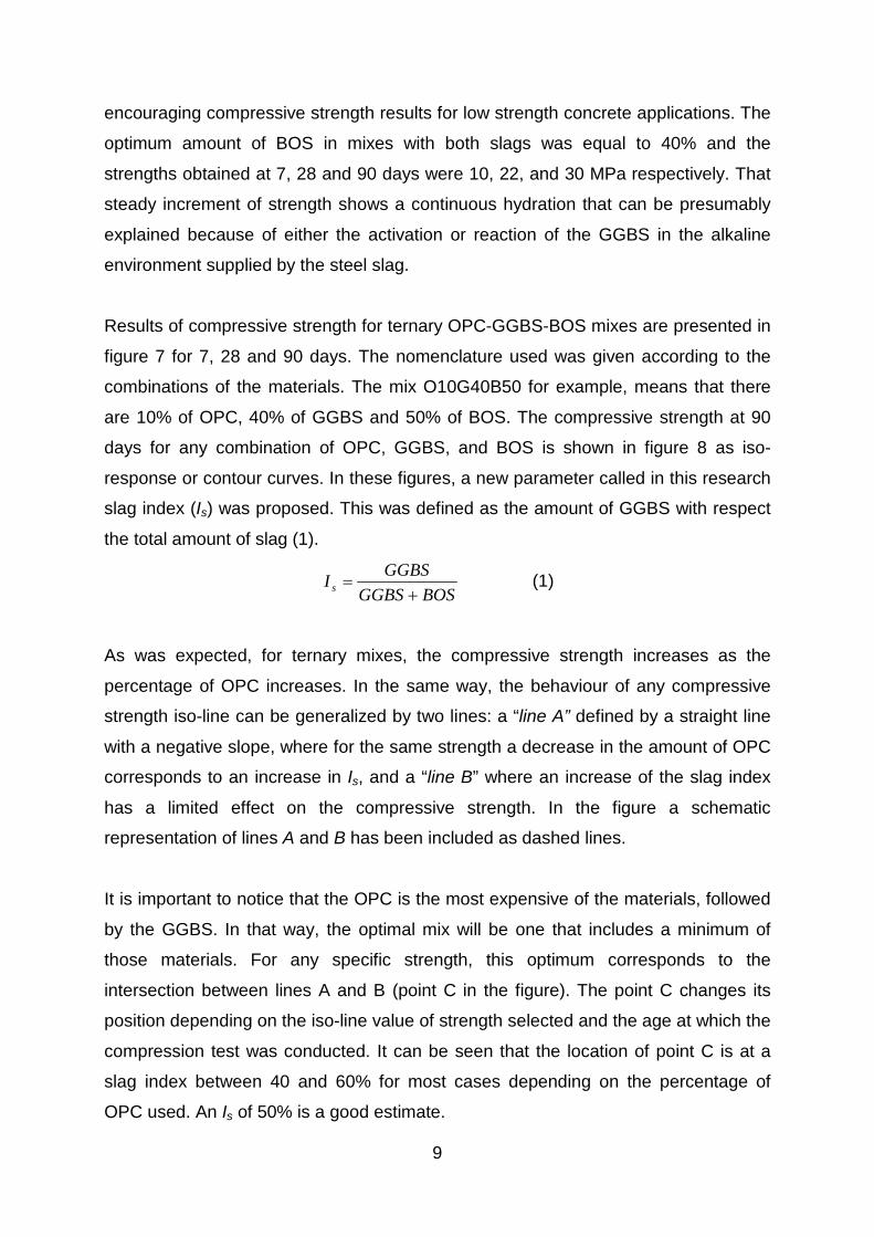
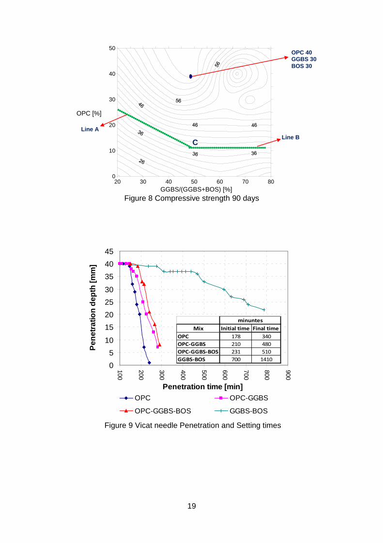
Results of compressive strength for ternary OPC-GGBS-BOS mixes are presented in
figure 7 for 7, 28 and 90 days. The nomenclature used was given according to the
combinations of the materials. The mix O10G40B50 for example, means that there
are 10% of OPC, 40% of GGBS and 50% of BOS. The compressive strength at 90
days for any combination of OPC, GGBS, and BOS is shown in figure 8 as iso-
response or contour curves. In these figures, a new parameter called in this research
slag index (Is) was proposed. This was defined as the amount of GGBS with respect
the total amount of slag (1).
BOSGGBSGGBSI s +
= (1)
As was expected, for ternary mixes, the compressive strength increases as the
percentage of OPC increases. In the same way, the behaviour of any compressive
strength iso-line can be generalized by two lines: a “line A” defined by a straight line
with a negative slope, where for the same strength a decrease in the amount of OPC
corresponds to an increase in Is, and a “line B” where an increase of the slag index
has a limited effect on the compressive strength. In the figure a schematic
representation of lines A and B has been included as dashed lines.
It is important to notice that the OPC is the most expensive of the materials, followed
by the GGBS. In that way, the optimal mix will be one that includes a minimum of
those materials. For any specific strength, this optimum corresponds to the
intersection between lines A and B (point C in the figure). The point C changes its
position depending on the iso-line value of strength selected and the age at which the
compression test was conducted. It can be seen that the location of point C is at a
slag index between 40 and 60% for most cases depending on the percentage of
OPC used. An Is of 50% is a good estimate.
10
4.2 Properties of slag mixtures
The setting times were measured for the four binders stated in the table 2. The
change of the penetration depth during the first hours after mixing is shown in figure
9, where a period can be seen for all binders with practically no penetration
resistance and a period where the penetration resistance increases linearly with time.
There are significant differences in the rate of initial setting for samples with and
without Portland cement; in OPC mixes the addition of any slag produces a relatively
short delay in the start of setting. The mix OPC-GGBS showed an increase in the
initial and final setting times of 18 and 41% respectively, and the mix OPC-GGBS-
BOS showed an increase in the initial and final setting times of 30% and 50%
respectively. All GGBS mixes activated with OPC had values of initial setting time in
the range suggested by ASTM C150 (2007): >45 min and <375 min. In contrast, the
mix GGBS-BOS showed a prolonged delay in the initial and final setting times, those
were 293 and 315 % longer than the OPC sample.
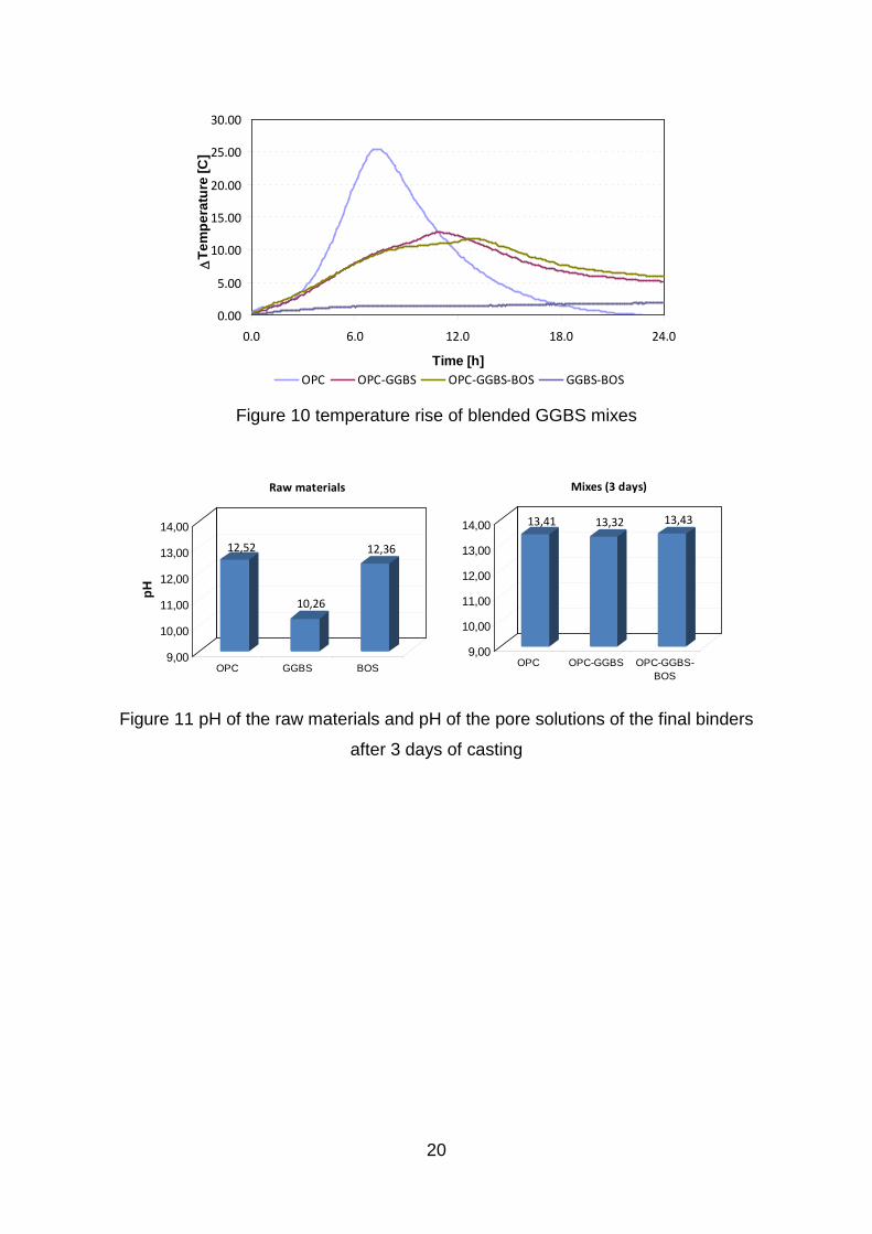
The early age development of temperature measured in an adiabatic cell during the
first 24 hours of hydration is shown in figure 10. Although the rate of temperature rise
and the maximum temperatures were different for each binder, all samples had a
similar profile: a sustained increase of the temperature until a maximum value was
reached followed by a sustained temperature decreasing. It is important to notice that
some slag samples had a secondary local maximum. In the OPC reference sample
the temperature increased rapidly during the first 7 hours and reached a maximum
increment of 25°C, after this time the sample started to reduce temperature until 22
hours when the temperature increase was negligible.
In the samples OPC-GGBS and OPC-GGBS-BOS in addition to the maximum peak,
some local or secondary maximum points were measured. These local maximum
peaks appeared a couple hours before the maximum peak and were followed in all
cases by an inflection point. This behaviour reported by Roy and Idorn (1982) is
characteristic of the early age hydration of GGBS, and Shy and Day (1995) state that
the secondary peaks are the result of chemical reactions of the granulated slag and
the alkalis used as activators. In the same way, De Schutter (1999) affirms that the
reason for the presence of temperature multi-peaks can be explained by the fact that

11
the hydration of slag cements is due of two reactions: a Portland reaction and a slag-
alkali reaction.
The temperature rise for mixes OPC-GGBS and OPC-GGBS-BOS was very similar.
The maximum peak measured was around 12°C, however, in the ternary binder
there was a delay of 2 hours approximately. At 24 hours for both samples there were
remaining increments of temperature. The profile of the binder GGBS-BOS showed
that by itself it is able to develop some exothermic reactions. The granulated slag is
activated by the steel slag, and although the values obtained do not show strong
reactions, it can be considerate by itself a poor hydraulic binder.
The results of pH for the raw materials are shown in figure 11-left. The pH depends
on the concentration so the powders were all hydrated with a water binder ratio of
0.5, to obtain the differences in alkalinity. The GGBS, for example, showed the
lowest value of alkalinity. According to Taylor (1990), this result can explain why if
granulated slag is mixed alone with water it can develop just a small degree of
hydration. As was stated before, a protective film deficient in Ca+ inhibits further
reaction, but if the pH is kept sufficiently high the reaction continues. The lower
basicity of GGBS compared with the Portland cement has been reported previously
by Tailing and Krivenko (1997). In a research by Song and Jennings (1999), it was
established that the pH of a mixing solution must be higher than 11.5 to activate the
GGBS. They state that in a pH lower that 11.5 the solubility of silica is low and GGBS
does not dissolve and form silicate hydrates as principal compounds. The pH of the
Portland cement and steel slag is higher than the blast furnace slag, and presumably
influenced their alkaline activation.
The pH of the pore solution of the final binders after 48 hours of hydration is shown in
figure 11-right. Although the lime and metal alkali contents for OPC are considerably
higher than for BOS (table 1), the pH of the extracted pore solution of the sample of
OPC-GGBS-BOS was slightly higher than the OPC binder. This was because most
of the lime in the BOS did not form any hydration compounds and remained partly
free in the pore solution.
12
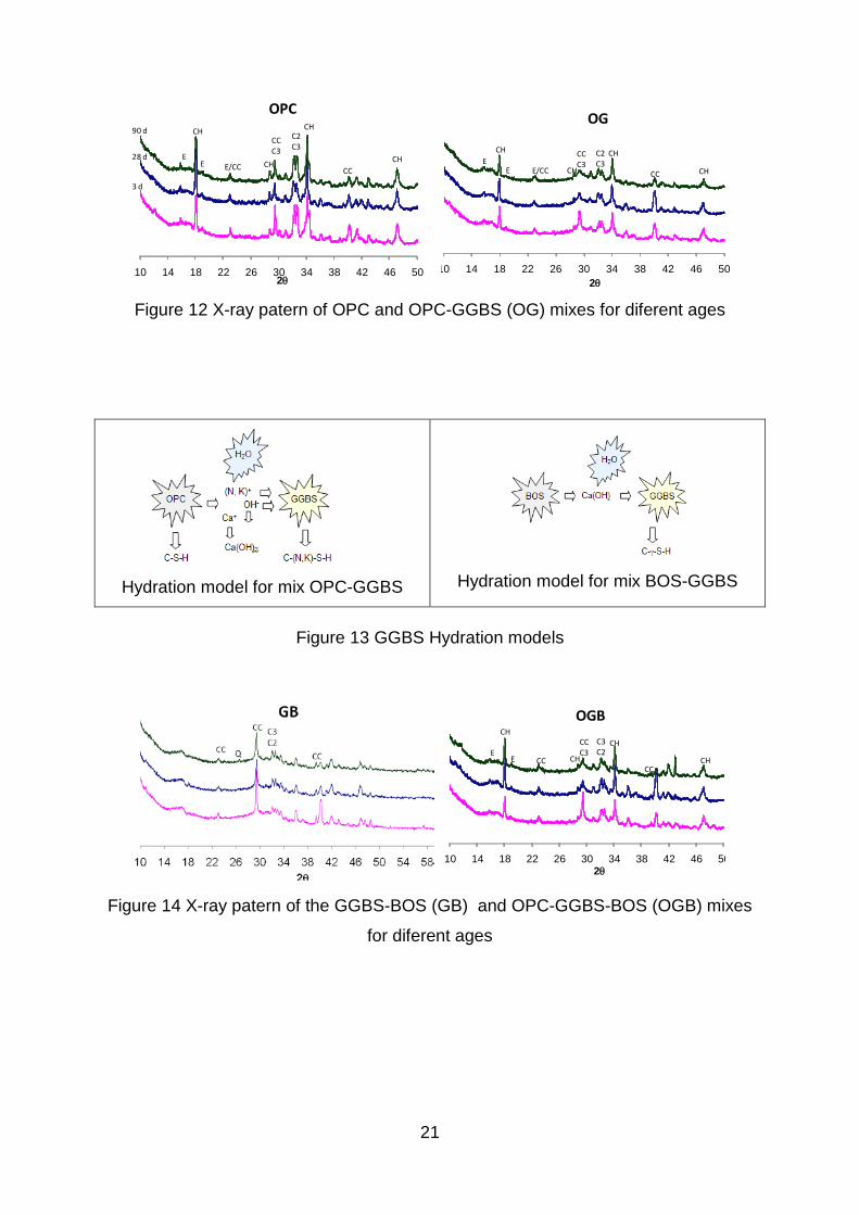
The development of the final binders with time determined by XRD is shown in
figures 12 and 14. They show the X-ray pattern obtained after 3, 28 and 90 days of
curing under controlled conditions of temperature and humidity. Although the
principal crystalline hydration products were determined, it was not possible to
observe the amorphous CSH gel by means of this technique.
The X-ray data for the 100% Portland cement reference (OPC), figure 12, shows a
normal pattern which is discussed extensively in references books (Taylor 1990;
Hewlett 1988). Calcium hydroxide, known as portlandite (CH), was formed in
significant quantities from the early ages as the result of the hydration of calcium
silicates. This compound remained stable throughout the period of investigation.
Calcite or calcium carbonate (CC) was present, probably due to small amounts of
limestone in the Portland cement. During the mixing and curing the contact of the
samples with carbon dioxide was limited, although during the x-ray preparation of the
samples or even during the x-ray scanning there could have been some minor
carbonation. It is believed that the carbonation, if present, was minimal and is not
responsible for the presence of calcium carbonate. The peak found at 29.4°2θ
overlaps the calcite and the C3S or alite (C3), however it decreases during curing
meaning that some cement compounds had a hydration delay. At three days, there
were some un-hydrated calcium silicates (C3, C2). They decrease in intensity during
curing, but at 90 day there were some remaining. As was expected, ettringite (E) was
present as a stable compound.
The X ray traces for the 40% Portland cement and 60% blast furnace slag mix are
shown also in figure 12. The system had similar hydration products to Portland
cement; however, the intensity of portlandite was lower because a smaller amount of
OPC was used. It can be noted that during all the period studied there are no
differences in the amount of calcium hydroxide and it remains constant. From this
observation, it is shown that during the hydration of GGBS in a Portland cement
system the slag does not consume the calcium hydroxide available. The alkalis
released from Portland cement are responsible for activating the slag as is shown in
the model of figure 13 (Roy and Idorn (1982). Other minerals found in the pattern
were calcite, anhydrous calcium silicates and ettringite.

13
The X ray pattern for the 60%GGBS+40%BOS mix is shown in figure 14. This mix
does not have any Portland cement addition and is made up entirely of slag. It is
important to notice that from the X-ray pattern there is not evidence of the presence
of calcium hydroxide. This compound was abundant in the non-hydrated steel slag,
but is not present in the hydrated binary slag mix. The absence of portlandite can be
explained qualitatively in figure 13-right where the proposed mechanism of hydration
for the GGBS-BOS mix is shown. This consists of the consumption of the calcium
hydroxide supplied by the BOS in reactions of GGBS before 3 days of hydration,
producing some sort of calcium silicate hydrates (C-γ-S-H). Although this C-γ-S-H gel
sets and develops some strength, it is much weaker than that obtained from the slag
reaction with OPC. It is believed that this mechanism of hydration can occur
principally in non-Portland mixes.
The pattern for the ternary 40%OPC+30%GGBS+30%BOS mix is shown also in
figure 14. It can be seen that the peaks follow the pattern left by the cement hydration
and similar minerals were obtained. For this mix, the mechanisms of hydration can
be summarized as follows: the hydration of the OPC by itself and the hydration of the
slag through the alkalis available. In this ternary mix there is no evidence of calcium
hydroxide consumption, according to the X-ray diffraction patterns the lime increased
with time.
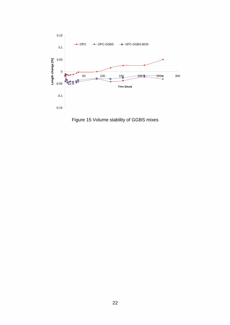
The length change of samples was measured for OPC, OPC-GGBS, and OPC-
GGBS-BOS at different days and results are reported as percentage at different ages
in figure 15. No considerable expansion or shrinkage was measured for any of the
mixes; all the ranges are smaller than 0.05% and are relatively stable in time. No
expansion was measured in the mix containing BOS, in contrast with the reported in
the literature. The dimensional stability of the mix containing BOS is attributed to the
weathered condition of the steel slag and the compensation due to the trend of the
GGBS to have some shrinkage.
5. Conclusions
The main conclusions may be drawn from the above findings are:
14
1. The influence of the replacement level of ordinary Portland cement and steel
slag on the compressive strength of ground granulated blast furnace slag
blended binders has been studied in detail. A proposed parameter called “slag
index” has been introduced and the optimal value found was 0.5 in samples
with OPC.
2. The steel slag used in this research can be used as activator for GGBS. The
material, weathered naturally under laboratory conditions, can be used
effectively in ternary mixes composed of OPC-GGBS-BOS.
3. No expansion was measured in the mixes tested; it gives encouraging results
for the potential use of blended mixes of weathered steel and blast furnace
slag.
4. REFERENCES
ACI-233 (2003) 233R-03: Slag Cement in Concrete and Mortar. ACI - American Concrete Institute.
AKIN ALTUN, I. & YILMAZ, I. (2002) Study on steel furnace slags with high MgO as additive in Portland cement. Cement and Concrete Research, 32, 1247-1249.
ASTM-C109 Standard Test Method for Compressive Strength of Hydraulic Cement Mortars (Using 2-in. or [50-mm] Cube Specimens).
ASTM-C150 (2007) Standard Specification for Portland Cement. ASTM-C187 (2004) Standard Test Method for Normal Consistency of Hydraulic
Cement. ASTM-C191 (2008) Standard Test Methods for Time of Setting of Hydraulic Cement
by Vicat Needle. ASTM-C490 (1997) Standard Practice for Use of Apparatus for the Determination of
Length Change of Hardened Cement Paste, Mortar, and Concrete ASTM-C595 (2008) Standard Specification for Blended Hydraulic Cements. BARNEYBACK JR, R. S. & DIAMOND, S. (1981) Expression and analysis of pore
fluids from hardened cement pastes and mortars. Cement and Concrete Research, 11, 279-285.
BIN, Q., WU, X. & TANG, M. (1992) High strength alkali steel–iron slag binder. Proc., 9th Int. Congress on the Chemistry of Cement. New Delhi, India.
CHATTERJEE, A. K. (2001) X-Ray Diffraction. IN RAMACHANDRAN, V. S. & BEAUDOIN, J. J. (Eds.) Handbook of Analytical Techniques in Concrete Science and Technology. NOYES PUBLICATIONS.
DE SCHUTTER, G. (1999) Hydration and temperature development of concrete made with blast-furnace slag cement. Cement and Concrete Research, 29, 143-149.
DETWILER, R., BHATTY, J. & BHATTACHARJA, S. (1996) Supplementary Cementing Materials for Use in Blended Cements PCA-RD112.
GEISELER, J. (1996) Use of steelworks slag in Europe. Waste Management, 16, 59-63.
15
HEWLETT, P. (1988) Lea's Chemistry of Cement and Concrete. KOUROUNIS, S., TSIVILIS, S., TSAKIRIDIS, P. E., PAPADIMITRIOU, G. D. &
TSIBOUKI, Z. (2007) Properties and hydration of blended cements with steelmaking slag. Cement and Concrete Research, 37, 815-822.
MAHIEUX, P. Y., AUBERT, J. E. & ESCADEILLAS, G. (2009) Utilization of weathered basic oxygen furnace slag in the production of hydraulic road binders. Construction and Building Materials, 23, 742-747.
MATSCHEI, T., BELLMANN, F. & STARK, J. (2005) Hydration behaviour of sulphate-activated slag cements. Advances in Cement Research, 17.
MONSHI, A. & ASGARANI, M. K. (1999) Producing Portland cement from iron and steel slags and limestone. Cement and Concrete Research, 29, 1373-1377.
QASRAWI, H., SHALABI, F. & ASI, I. (2009) Use of low CaO unprocessed steel slag in concrete as fine aggregate. Construction and Building Materials, 23, 1118-1125.
RAI, A., PRABAKAR, J., RAJU, C. B. & MORCHALLE, R. K. (2002) Metallurgical slag as a component in blended cement. Construction and Building Materials, 16, 489-494.
ROY, D. M. & LDORN, G. M. (1982) Hydration, Structure, and Properties of Blast Furnace Slag Cements, Mortars, and Concrete. ACI -Journal Proceedings, 79.
SAJKATA, AYANO & FUJII (2007) Steel making slag concrete as sustainable construction materials. Sustainable construction materials and technologies Coventry, UK.
SHI, C. (2004) Steel Slag—Its Production, Processing, Characteristics, and Cementitious Properties. J. Mat. in Civ. Engrg, 16, 230-236
SHI, C. & DAY, R. L. (1995) A calorimetric study of early hydration of alkali-slag cements. Cement and Concrete Research, 25, 1333-1346.
SONG, S. & JENNINGS, H. M. (1999) Pore solution chemistry of alkali-activated ground granulated blast-furnace slag. Cement and Concrete Research, 29, 159-170.
TAILING, B. & KRIVENKO, P. (1997) Blast Furnace Slag – The Ultimate Binder. IN CHANDRA, S. (Ed.) Waste Materials used in Concrete Manufacturing.
TAYLOR, H. F. W. (1990) Cement Chemistry, Academic Press. TSAKIRIDIS, P. E., PAPADIMITRIOU, G. D., TSIVILIS, S. & KORONEOS, C. (2008)
Utilization of steel slag for Portland cement clinker production. Journal of Hazardous Materials, 152, 805-811.
XUEQUAN, W., HONG, Z., XINKAI, H. & HUSEN, L. (1999) Study on steel slag and fly ash composite Portland cement. Cement and Concrete Research, 29, 1103-1106.

16
Specific Chemical composition [%]
Binder Gravity SiO2 TiO2 Al2O3 Fe2O3 MnO MgO CaO Na2O K2O P2O5 SO3 LOI
OPC* 3.11 19.7 --- 4.9 2.4 --- 2.1 63.3 0.2 0.6 --- 2.7 2.7
GGBS 2.94 34.5 0.55 13.16 0.74 0.45 7.75 38.7 0.29 0.55 0.02 1.75 0.7
BOS 3.49 11.45 0.37 2.32 27.32 3.65 9.32 37.44 0.03 0.01 1.26 0.28 3.12
Table 1 Chemical oxide composition (*according to the producer)
Binder Materials Binder name 1 100% OPC (reference) OPC 2 40% OPC + 60% GGBS OPC-GGBS 3 40% OPC + 30% GGBS + 30% BOS OPC-GGBS-BOS 4 60%GGBS+40%BOS GGBS-BOS
Table 2 Final mixes tested
Figure 1 XRD analyses of OPC
Figure 2 XRD analyses of GGBS
17
Figure 3 XRD analyses of BOS
GGBS
0 10 20 30 40 50 60 70 80 90 100
BOS
0
10
20
30
40
50
60
70
80
90
100
OPC
0
10
20
30
40
50
60
70
80
90
100
Figure 4 Compressive strength mixtures tested

18
0
10
20
30
40
50
60
70
80
0 20 40 60 80 100GGBS percentage by weigth [%]
Stre
ngth
[MPa
]7 Days28 Days90 days
Figure 5 Compressive strength of OPC-GGBS mixes
05
101520253035404550
0 20 40 60 80 100
BOS percentage by weigth [%]
Stre
ngth
[MPa
]
7 days28 days90 days
Figure 6 Compressive strength of BOS-GGBS mixes
0
10
20
30
40
50
60
70
80
O10G40
B50
O10G50
B40
O20G20
B60
O20G40
B40
O20G60
B20
O30G10
B60
O30G30
B40
O30G50
B20
O40G20
B40
O40G30
B30
O40G40
B20
O50G10
B40
O50G30
B20
Stre
ngth
[MPa
]
7 days28 days90 days
Figure 7 Compressive strength ternary mixes OPC-GGBS-BOS
19
20 30 40 50 60 70 800
10
20
30
40
50
Figure 8 Compressive strength 90 days
Figure 9 Vicat needle Penetration and Setting times
OPC [%]
GGBS/(GGBS+BOS) [%]
C
OPC 40 GGBS 30 BOS 30
05
10
15202530
354045
100
200
300
400
500
600
700
800
900
Penetration time [min]
Pene
tratio
n de
pth
[mm
]
OPC OPC-GGBS
OPC-GGBS-BOS GGBS-BOS
Mix Initial time Final timeOPC 178 340OPC-GGBS 210 480OPC-GGBS-BOS 231 510GGBS-BOS 700 1410
minuntes
Line A Line B
20
0.00
5.00
10.00
15.00
20.00
25.00
30.00
0.0 6.0 12.0 18.0 24.0
Time [h]
∆Te
mpe
ratu
re [C
]
OPC OPC-GGBS OPC-GGBS-BOS GGBS-BOS Figure 10 temperature rise of blended GGBS mixes
Figure 11 pH of the raw materials and pH of the pore solutions of the final binders
after 3 days of casting
12,52
10,26
12,36
9,00
10,00
11,00
12,00
13,00
14,00
pH
OPC GGBS BOS
Raw materials
13,41 13,32 13,43
9,00
10,00
11,00
12,00
13,00
14,00
OPC OPC-GGBS OPC-GGBS-BOS
Mixes (3 days)
21
10 14 18 22 26 30 34 38 42 46 502θ
OPC
E
CH
E/CC
CHCCC3
CH
C2C3
CH
3 d
28 d
90 d
ECC
10 14 18 22 26 30 34 38 42 46 50
2θ
OG
ECH
E/CC
C2C3
CH
CCC3
CH
CHE CC
Figure 12 X-ray patern of OPC and OPC-GGBS (OG) mixes for diferent ages
Hydration model for mix OPC-GGBS
Hydration model for mix BOS-GGBS
Figure 13 GGBS Hydration models
10 14 18 22 26 30 34 38 42 46 50
2θ
OGB
E
CH
E CC CH
CCC3
C3C2
CH
CH
CC
Figure 14 X-ray patern of the GGBS-BOS (GB) and OPC-GGBS-BOS (OGB) mixes
for diferent ages
22
-0.15
-0.1
-0.05
0
0.05
0.1
0.15
0 50 100 150 200 250 300
Time [Days]
Leng
th c
hang
e [%
]
OPC OPC-GGBS OPC-GGBS-BOS
Figure 15 Volume stability of GGBS mixes