diaphragm liquid pump nf 60, nfb 60 - knf usa liquid pump nf 60, nfb 60 operating and ... knf flodos...
TRANSCRIPT
KNF Flodos AG BA_NF60_EN_04_069208 Translated from the Original Operating and Installation Instructions Keep for future reference!
DIAPHRAGM LIQUID PUMP
NF 60, NFB 60
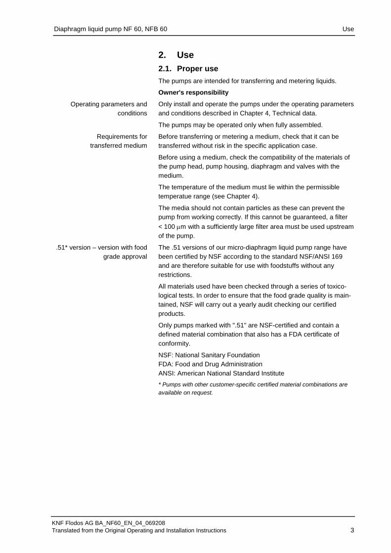
Operating and Installation Instructions Read and observe these oper-ating and installation instruc-tions! An additional letter prefixing the NF model code is a country-specific designation and has no technical relevance.
Contents Page
1. About this document ................................................................. 2 2. Use ........................................................................................... 3 3. Safety ....................................................................................... 5 4. Technical data .......................................................................... 7 5. Assembly and function ........................................................... 10 6. Installation and connection ..................................................... 11 7. Operation ................................................................................ 16 8. Servicing ................................................................................. 19 9. Troubleshooting ...................................................................... 22 10. Decontamination declaration .................................................. 24
KNF Flodos AG Wassermatte 2 6210 Sursee, Switzerland Tel. +41 (0)41 925 00 25 Fax +41 (0)41 925 00 35 www.knf-flodos.ch [email protected]
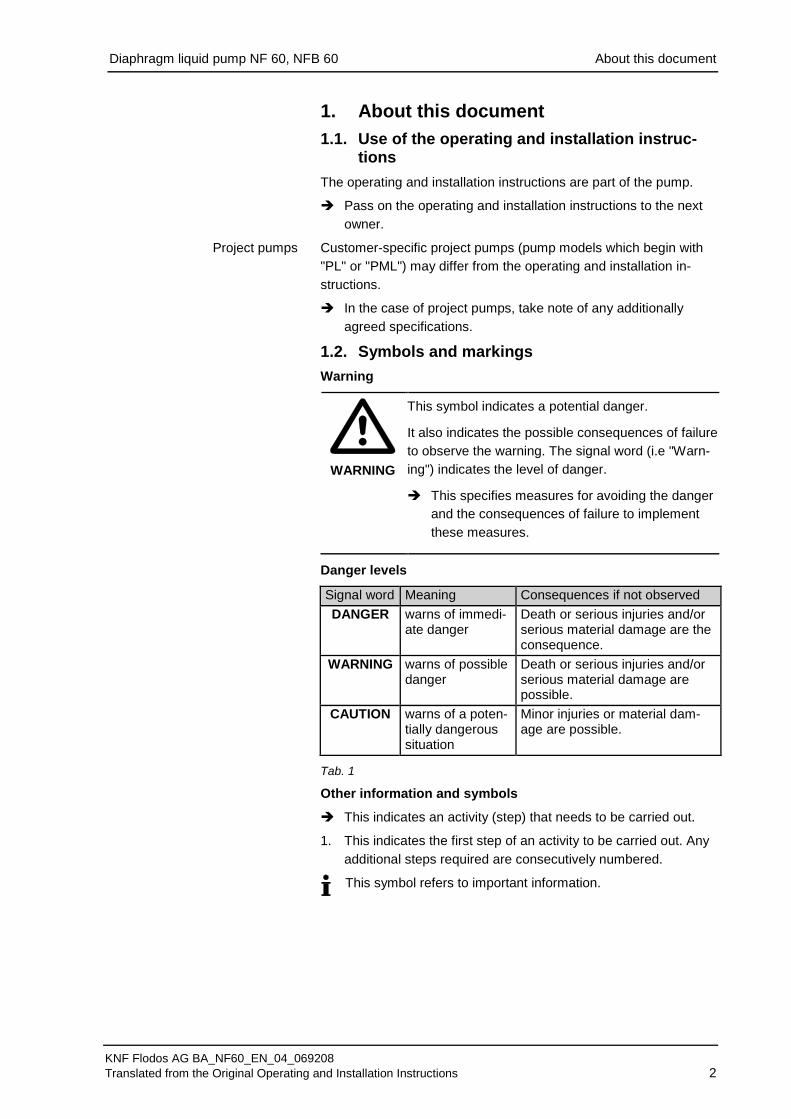
NF 60 KP .51 DC 12V
Supply voltage [Ch. 4]
.51 / - [Ch. 2] KP / KV / KT / TV / TT / FT [Ch. 4]
NF / UNF / NFB
60
- / PMLxxxx / PLxxxx [Ch. 1]
E / DC / DCB / DCB-A
Diaphragm liquid pump NF 60, NFB 60 About this document
KNF Flodos AG BA_NF60_EN_04_069208 Translated from the Original Operating and Installation Instructions 2
1. About this document 1.1. Use of the operating and installation instruc-
tions The operating and installation instructions are part of the pump.
Pass on the operating and installation instructions to the next owner.
Customer-specific project pumps (pump models which begin with "PL" or "PML") may differ from the operating and installation in-structions.
In the case of project pumps, take note of any additionally agreed specifications.
1.2. Symbols and markings Warning
WARNING
This symbol indicates a potential danger. It also indicates the possible consequences of failure to observe the warning. The signal word (i.e "Warn-ing") indicates the level of danger. This specifies measures for avoiding the danger
and the consequences of failure to implement these measures.
Danger levels
Signal word Meaning Consequences if not observed DANGER warns of immedi-
ate danger Death or serious injuries and/or serious material damage are the consequence.
WARNING warns of possible danger
Death or serious injuries and/or serious material damage are possible.
CAUTION warns of a poten-tially dangerous situation
Minor injuries or material dam-age are possible.
Tab. 1
Other information and symbols
This indicates an activity (step) that needs to be carried out.
This indicates the first step of an activity to be carried out. Any 1. additional steps required are consecutively numbered.
This symbol refers to important information.
Project pumps
Diaphragm liquid pump NF 60, NFB 60 Use
KNF Flodos AG BA_NF60_EN_04_069208 Translated from the Original Operating and Installation Instructions 3
2. Use 2.1. Proper use The pumps are intended for transferring and metering liquids.
Owner's responsibility
Only install and operate the pumps under the operating parameters and conditions described in Chapter 4, Technical data.
The pumps may be operated only when fully assembled.
Before transferring or metering a medium, check that it can be transferred without risk in the specific application case.
Before using a medium, check the compatibility of the materials of the pump head, pump housing, diaphragm and valves with the medium.
The temperature of the medium must lie within the permissible temperatue range (see Chapter 4).
The media should not contain particles as these can prevent the pump from working correctly. If this cannot be guaranteed, a filter < 100 µm with a sufficiently large filter area must be used upstream of the pump.
The .51 versions of our micro-diaphragm liquid pump range have been certified by NSF according to the standard NSF/ANSI 169 and are therefore suitable for use with foodstuffs without any restrictions.
All materials used have been checked through a series of toxico-logical tests. In order to ensure that the food grade quality is main-tained, NSF will carry out a yearly audit checking our certified products.
Only pumps marked with ".51" are NSF-certified and contain a defined material combination that also has a FDA certificate of conformity.
NSF: National Sanitary Foundation FDA: Food and Drug Administration ANSI: American National Standard Institute
* Pumps with other customer-specific certified material combinations are available on request.
Operating parameters and conditions
Requirements for transferred medium
.51* version – version with food grade approval
Diaphragm liquid pump NF 60, NFB 60 Use
KNF Flodos AG BA_NF60_EN_04_069208 Translated from the Original Operating and Installation Instructions 4
All certified micro-diaphragm liquid pumps are clearly marked with “.51” in the type designation along with the NSF-logo on the type plate. If either or both of these markings are missing, the pump is not certified.
Because the cleaning requirements of the micro-diaphragm liquid pumps depend on the application, KNF is unable to guarantee cleaning options. The responsibility for cleaning the pump(s) therefore lies with the user. While the NSF/ANSI 169 standard regulates OEM products, it does not define cleaning methods for specific OEM products.
All parts in contact with the medium can be replaced as spare parts without losing the certification. Component parts cannot be traded as certified parts. When replacing parts/assemblies only use original KNF parts.
2.2. Improper use The pumps may not be operated in an explosive atmosphere. For special modifications outside the standard technical specifica-tions, please contact a KNF pump specialist.
Diaphragm liquid pump NF 60, NFB 60 Safety
KNF Flodos AG BA_NF60_EN_04_069208 Translated from the Original Operating and Installation Instructions 5
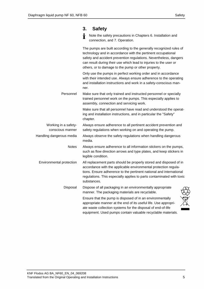
3. Safety
Note the safety precautions in Chapters 6. Installation and connection, and 7. Operation.
The pumps are built according to the generally recognized rules of technology and in accordance with the pertinent occupational safety and accident prevention regulations. Nevertheless, dangers can result during their use which lead to injuries to the user or others, or to damage to the pump or other property.
Only use the pumps in perfect working order and in accordance with their intended use. Always ensure adherence to the operating and installation instructions and work in a safety-conscious man-ner.
Make sure that only trained and instructed personnel or specially trained personnel work on the pumps. This especially applies to assembly, connection and servicing work.
Make sure that all personnel have read and understood the operat-ing and installation instructions, and in particular the "Safety" chapter.
Always ensure adherence to all pertinent accident prevention and safety regulations when working on and operating the pump.
Always observe the safety regulations when handling dangerous media.
Always ensure adherence to all information stickers on the pumps, such as flow direction arrows and type plates, and keep stickers in legible condition.
All replacement parts should be properly stored and disposed of in accordance with the applicable environmental protection regula-tions. Ensure adherence to the pertinent national and international regulations. This especially applies to parts contaminated with toxic substances.
Dispose of all packaging in an environmentally appropriate manner. The packaging materials are recyclable.
Ensure that the pump is disposed of in an environmentally appropriate manner at the end of its useful life. Use appropri-ate waste collection systems for the disposal of end-of-life equipment. Used pumps contain valuable recyclable materials.
Personnel
Working in a safety- conscious manner
Handling dangerous media
Notes
Environmental protection
Disposal
Diaphragm liquid pump NF 60, NFB 60 Safety
KNF Flodos AG BA_NF60_EN_04_069208 Translated from the Original Operating and Installation Instructions 6
The pumps are in accordance with the requirements of the guide-lines 2011/65/EU (ROHS2)
The pumps conform to EU safety requirements and guidelines for Electromagnetic interference 2004/108/EC.
As defined in the Machinery Directive 2006/42/EC, pumps are partly completed machines and not ready-for-use, the overall equipment must be made to fully conform with the requirements of the Directive before being brought into service. Always ensure implementation and enforcement of the basic requirements of the Machinery Directive 2006/42/EC according to Appendix I (General Principles).
The following harmonised standards are met:
NF 60 E
EN 55014 - 1
NF 60 DC
EN 55014 - 1
NF 60 DCB1)
EN 55011
EN 55022
NF 60 DCB-A
EN 55014-1/2
EN 55022-6-1/3
NFB 60 DCB1)
EN 55011
EN 55022 1)In order to comply with the specified standards, the pump must be connected as described in Chapter 6.2.
All repairs to the pump(s) must be carried out by the relevant KNF Customer Service team.
Only use KNF original parts for all maintenance work.
EU directives/standards
Customer service and repairs

Diaphragm liquid pump NF 60, NFB 60 Technical data
KNF Flodos AG BA_NF60_EN_04_069208 Translated from the Original Operating and Installation Instructions 7
4. Technical data Pump materials
The pump type KP / KP.51 stands for:
Assembly Material1) Pump head * PP Valve plate EPDM Diaphragm PTFE Resonating diaphragm PTFE O-ring EPDM
Tab. 2 1) according to DIN ISO 1629 and 1043.1
The pump type KV stands for:
Assembly Material1) Pump head * PP Valve plate FPM Diaphragm PTFE Resonating diaphragm PTFE O-ring FPM
Tab. 3 1) according to DIN ISO 1629 and 1043.1
The pump type KT stands for:
Assembly Material1) Pump head * PP Valve plate FFPM Diaphragm PTFE Resonating diaphragm PTFE O-ring PTFE
Tab. 4 1) according to DIN ISO 1629 and 1043.1
The pump type TV stands for:
Assembly Material1) Pump head * PVDF Valve plate FPM Diaphragm PTFE Resonating diaphragm PTFE O-ring FPM
Tab. 5 1) according to DIN ISO 1629 and 1043.1
The pump type TT stands for:
Assembly Material1) Pump head * PVDF Valve plate FFPM Diaphragm PTFE Resonating diaphragm PTFE O-ring PTFE
Tab. 6 1) according to DIN ISO 1629 and 1043.1
Diaphragm liquid pump NF 60, NFB 60 Technical data
KNF Flodos AG BA_NF60_EN_04_069208 Translated from the Original Operating and Installation Instructions 8
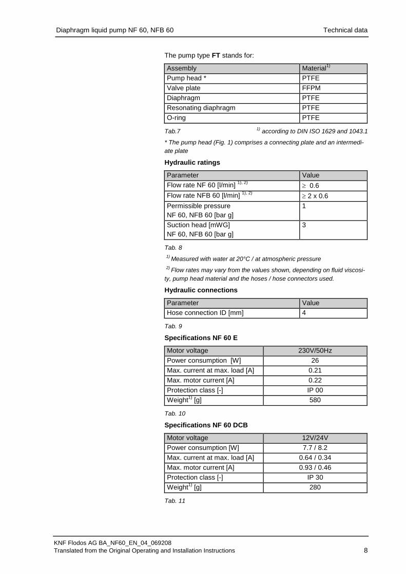
The pump type FT stands for:
Assembly Material1) Pump head * PTFE Valve plate FFPM Diaphragm PTFE Resonating diaphragm PTFE O-ring PTFE
Tab.7 1) according to DIN ISO 1629 and 1043.1
* The pump head (Fig. 1) comprises a connecting plate and an intermedi-ate plate
Hydraulic ratings
Parameter Value Flow rate NF 60 [l/min] 1), 2) ≥ 0.6 Flow rate NFB 60 [l/min] 1), 2) ≥ 2 x 0.6 Permissible pressure NF 60, NFB 60 [bar g]
1
Suction head [mWG] NF 60, NFB 60 [bar g]
3
Tab. 8
1) Measured with water at 20°C / at atmospheric pressure
2) Flow rates may vary from the values shown, depending on fluid viscosi-ty, pump head material and the hoses / hose connectors used.
Hydraulic connections
Parameter Value Hose connection ID [mm] 4
Tab. 9
Specifications NF 60 E
Motor voltage 230V/50Hz Power consumption [W] 26 Max. current at max. load [A] 0.21 Max. motor current [A] 0.22 Protection class [-] IP 00 Weight1) [g] 580
Tab. 10
Specifications NF 60 DCB
Motor voltage 12V/24V Power consumption [W] 7.7 / 8.2 Max. current at max. load [A] 0.64 / 0.34 Max. motor current [A] 0.93 / 0.46 Protection class [-] IP 30 Weight1) [g] 280
Tab. 11
Diaphragm liquid pump NF 60, NFB 60 Technical data
KNF Flodos AG BA_NF60_EN_04_069208 Translated from the Original Operating and Installation Instructions 9
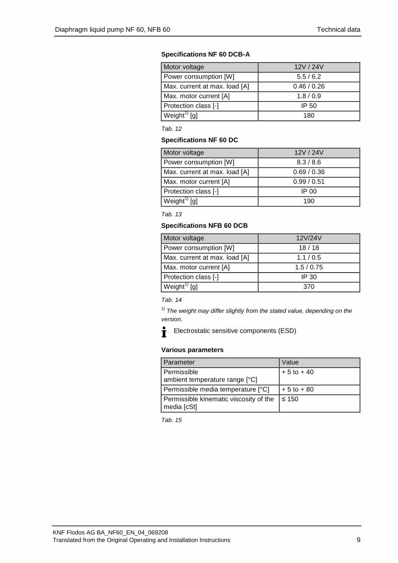
Specifications NF 60 DCB-A
Motor voltage 12V / 24V Power consumption [W] 5.5 / 6.2 Max. current at max. load [A] 0.46 / 0.26 Max. motor current [A] 1.8 / 0.9 Protection class [-] IP 50 Weight1) [g] 180
Tab. 12
Specifications NF 60 DC
Motor voltage 12V / 24V Power consumption [W] 8.3 / 8.6 Max. current at max. load [A] 0.69 / 0.36 Max. motor current [A] 0.99 / 0.51 Protection class [-] IP 00 Weight1) [g] 190
Tab. 13
Specifications NFB 60 DCB
Motor voltage 12V/24V Power consumption [W] 18 / 18 Max. current at max. load [A] 1.1 / 0.5 Max. motor current [A] 1.5 / 0.75 Protection class [-] IP 30 Weight1) [g] 370
Tab. 14 1) The weight may differ slightly from the stated value, depending on the version.
Electrostatic sensitive components (ESD)
Various parameters
Parameter Value Permissible ambient temperature range [°C]
+ 5 to + 40
Permissible media temperature [°C] + 5 to + 80 Permissible kinematic viscosity of the media [cSt]
≤ 150
Tab. 15

Diaphragm liquid pump NF 60, NFB 60 Assembly and function
KNF Flodos AG BA_NF60_EN_04_069208 Translated from the Original Operating and Installation Instructions 10
5. Assembly and function Assembly
1 Outlet 2 Inlet 3 Connecting plate 4 Motor 5 Head plate 6 Intermediate plate
Fig. 1: Micro-diaphragm liquid pump NF 60
1 Exhaust valve 2 Inlet valve 3 Working chamber 4 Diaphragm 5 Eccentric 6 Connecting rod 7 Pump drive
Fig. 2: Operating principle
Micro-diaphragm liquid pumps are based on reciprocating dis-placement pump technology. An elastic diaphragm (4) is moved up and down by the eccentric (5) and the connecting rod (6). During the down stroke, the diaphragm sucks in the medium through the inlet valve (2). During the up stroke, it forces medium out of the pump head through the exhaust valve (1). The diaphragm hermeti-cally seals off the working chamber (3) from the pump drive (7).
Diaphragm liquid pump NF 60, NFB 60 Installation and connection
KNF Flodos AG BA_NF60_EN_04_069208 Translated from the Original Operating and Installation Instructions 11
6. Installation and connection Only install and operate the pumps under the operating parameters and conditions described in Chapter 4, Technical data.
Observe the safety notes (see Chapter 3).
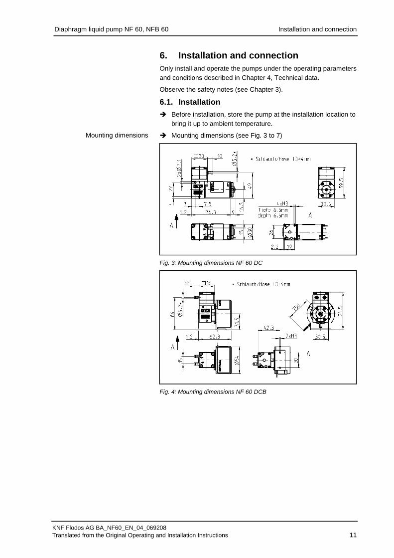
6.1. Installation Before installation, store the pump at the installation location to
bring it up to ambient temperature.
Mounting dimensions (see Fig. 3 to 7)
Fig. 3: Mounting dimensions NF 60 DC
Fig. 4: Mounting dimensions NF 60 DCB
Mounting dimensions
Diaphragm liquid pump NF 60, NFB 60 Installation and connection
KNF Flodos AG BA_NF60_EN_04_069208 Translated from the Original Operating and Installation Instructions 12
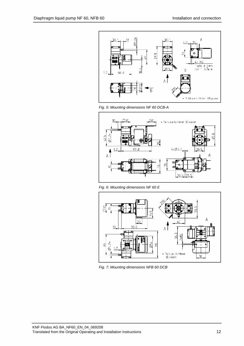
Fig. 5: Mounting dimensions NF 60 DCB-A
Fig. 6: Mounting dimensions NF 60 E
Fig. 7: Mounting dimensions NFB 60 DCB
Diaphragm liquid pump NF 60, NFB 60 Installation and connection
KNF Flodos AG BA_NF60_EN_04_069208 Translated from the Original Operating and Installation Instructions 13
For pumps with fan: mount the pump so that the fan of the motor can suck in sufficient cooling air.
Make sure that the installation location is dry and the pump is protected against rain, splashes, hose and drip water.
Protect the pump against dust.
Protect the pump against vibrations and jolts.
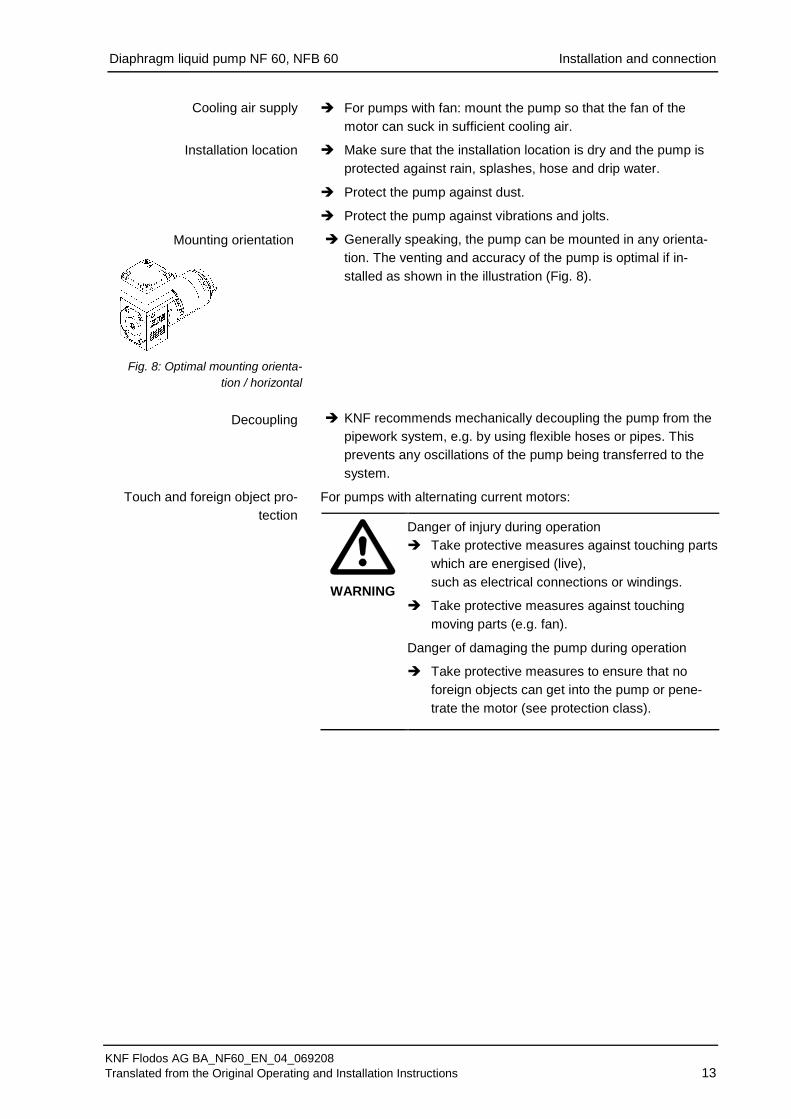
Generally speaking, the pump can be mounted in any orienta-tion. The venting and accuracy of the pump is optimal if in-stalled as shown in the illustration (Fig. 8).
KNF recommends mechanically decoupling the pump from the pipework system, e.g. by using flexible hoses or pipes. This prevents any oscillations of the pump being transferred to the system.
For pumps with alternating current motors:
WARNING
Danger of injury during operation Take protective measures against touching parts
which are energised (live), such as electrical connections or windings.
Take protective measures against touching moving parts (e.g. fan).
Danger of damaging the pump during operation
Take protective measures to ensure that no foreign objects can get into the pump or pene-trate the motor (see protection class).
Cooling air supply
Installation location
Fig. 8: Optimal mounting orienta-
tion / horizontal
Mounting orientation
Decoupling
Touch and foreign object pro-tection
Diaphragm liquid pump NF 60, NFB 60 Installation and connection
KNF Flodos AG BA_NF60_EN_04_069208 Translated from the Original Operating and Installation Instructions 14
6.2. Electrical connection For pumps with alternating current motors:
DANGER
Risk of electric shock, danger of death Pump should only be connected by a specialist.
Only connect the pump when the power supply is turned off.
For pumps with direct current motors:
Pump should only be connected by a specialist.
Only connect the pump when the power supply is turned off.
All electrical connection work must adhere to the pertinent guidelines, regulations and technical standards.
Connecting the pump
Make sure that the power supply data match the data on the 1. motor type plate. The current consumption can be found on the type plate.
Connect the motor cables. Electrical data Chapter 4. 2.
Always check polarity of cables.
For DC motors: red motor cable: + black motor cable: -
In the case of brushless DC motors: incorrect polarity may damage the electronics!
If using AC motors, the power supply must not deviate more than a maximum of +/- 10 % from the specifications on the type plate.
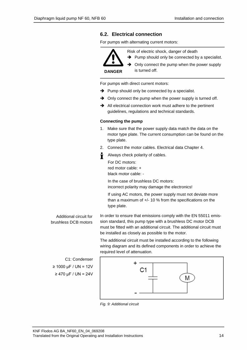
In order to ensure that emissions comply with the EN 55011 emis-sion standard, this pump type with a brushless DC motor DCB must be fitted with an additional circuit. The additional circuit must be installed as closely as possible to the motor.
The additional circuit must be installed according to the following wiring diagram and its defined components in order to achieve the required level of attenuation.
Fig. 9: Additional circuit
Additional circuit for brushless DCB motors
C1: Condenser
≥ 1000 µF / UN = 12V
≥ 470 µF / UN = 24V
Diaphragm liquid pump NF 60, NFB 60 Installation and connection
KNF Flodos AG BA_NF60_EN_04_069208 Translated from the Original Operating and Installation Instructions 15
6.3. Hydraulic connection Only connect components to the pump that are designed to
handle the hydraulic data of the pump (see Chapter 4, Tech-nical data).
Only use hoses that are suitable for the maximum operating pressure of the pump (see Chapter 4).
Only use hoses that are chemically resistant to the liquids being pumped.
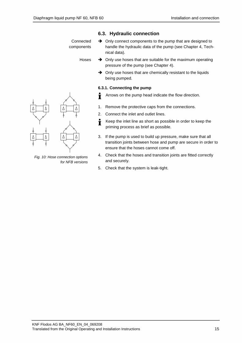
6.3.1. Connecting the pump
Arrows on the pump head indicate the flow direction.
Remove the protective caps from the connections. 1.
Connect the inlet and outlet lines. 2.
Keep the inlet line as short as possible in order to keep the priming process as brief as possible.
If the pump is used to build up pressure, make sure that all 3.
transition joints between hose and pump are secure in order to ensure that the hoses cannot come off.
Check that the hoses and transition joints are fitted correctly 4. and securely.
Check that the system is leak-tight. 5.
Connected components
Hoses
Fig. 10: Hose connection options
for NFB versions

Diaphragm liquid pump NF 60, NFB 60 Operation
KNF Flodos AG BA_NF60_EN_04_069208 Translated from the Original Operating and Installation Instructions 16
7. Operation The pumps should only be used under the operating parame-
ters/conditions described in Chapter 4, Technical data.
Ensure that the pumps are being used correctly (see Section 2.1).
Improper use of the pumps must be prevented (see Section 2.2).
Observe the safety notes (see Chapter 3).
Pumps are components intended to be incorporated into another machine. The machine/equipment in which the pumps are installed must be made to fully comply with the pertinent regulations before being put into operation.
CAUTION
Risk of burning The drive heats up. Avoid contact with the drive.
Avoid contact with flammable materials.
Excessive pressures and its inherent dangers can be prevent-ed by using a bypass system with a pressure relief valve between the pressure and suction side of the pump. Further information is available from your KNF adviser (Telephone number: see first page).
If the pump stops running, reduce the pressure in the system
until it is at normal atmospheric pressure.
For pumps with thermal switch or electronic overload protection:
WARNING
Risk of physical injury and damage to the pump due to automatic start If the pump overheats and the thermal switch / elec-tronics stops pump operation, the pumps will restart automatically as soon as they have had time to cool down. Take steps to ensure that this cannot produce a
hazardous situation.
Switching the pumps on and off
The motor speed of the pumps, and thus the flow rate, is adjusta-ble and can also be regulated to some extent.
For more details, see Chapter 4, Technical data. Duty cycle / impulse operation
KNF pumps are designed for continuous operation.
Short start and stop cycles may adversely affect the service life of the brushed motors.
Pump standstill
Adjusting and controlling the motor speed
Impulse operation
Diaphragm liquid pump NF 60, NFB 60 Operation
KNF Flodos AG BA_NF60_EN_04_069208 Translated from the Original Operating and Installation Instructions 17
If the pump is operated with short cycles in your application, please contact a KNF pump specialist for further information (Telephone number: see first page).
Turning the pump on
In order to guarantee that the pump can start every time it is advisable to reduce the back pressure to an acceptable level. This is also the case if there is a short power cut.
For more specific information contact the KNF specialist (Tele-phone number: see first page).
Turning the pump off
KNF recommends: If pumping aggressive liquids, the pump should be rinsed thoroughly prior to switch off (see Section 8.2.1), as this will help to lengthen the service life of the dia-phragm.
Ensure that the system is subject to normal atmospheric pres-sure (release the hydraulic pressure).
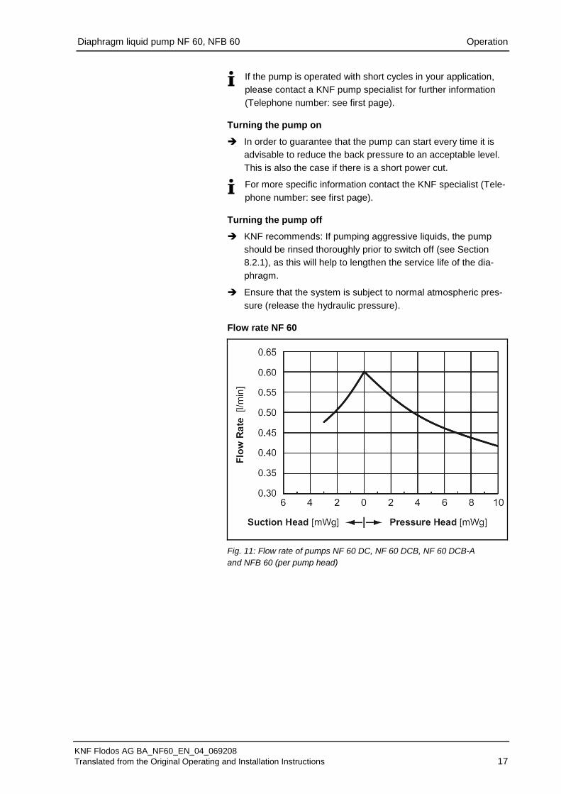
Flow rate NF 60
Fig. 11: Flow rate of pumps NF 60 DC, NF 60 DCB, NF 60 DCB-A and NFB 60 (per pump head)
Diaphragm liquid pump NF 60, NFB 60 Operation
KNF Flodos AG BA_NF60_EN_04_069208 Translated from the Original Operating and Installation Instructions 18
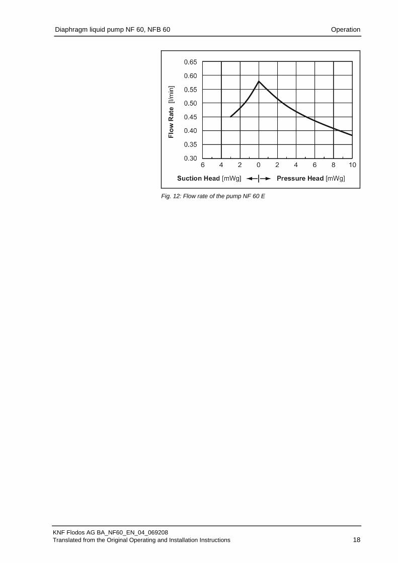
Fig. 12: Flow rate of the pump NF 60 E
Diaphragm liquid pump NF 60, NFB 60 Servicing
KNF Flodos AG BA_NF60_EN_04_069208 Translated from the Original Operating and Installation Instructions 19
8. Servicing 8.1. Servicing schedule Component Servicing interval Pump - Regular inspection for external
damage or leaks Pump head - Clean if the flow rate decreases, the
pump does not work or no vacuum is created (Section 8.2)
Diaphragm, valve plate and seals
- Change as soon as pumping capac-ity decreases, preferably sooner
Tab. 16
8.2. Cleaning
WARNING
Health hazard due to dangerous substances in the pump! Depending on the substance transferred, risk of caustic burns or poisoning. Wear protective clothing if necessary, e.g. pro-
tective gloves.
Rinse the pump with a neutral liquid and pump empty.
8.2.1. Flushing the pump
If pumping aggressive media, KNF recommends flushing the pump with air under atmospheric conditions for several minutes prior to switch off (if necessary for safety reasons: use an inert gas). This will extend the service life of the diaphragm.
8.2.2. Cleaning the pump
Where possible, wipe the components with a soft dry cloth. Do no use cleaning solvents as these may corrode plastic parts.
If there is compressed air available, blow off the separate parts.
Pump must be switched off and mains plug removed from
the socket.
The pump must be free of any hazardous substances.
Hoses must be disconnected from the pump head.
We recommend replacing the diaphragm when the head parts are removed.
Qty. Tool 1 Torxplus 10 IP screwdriver
Tab. 17
Information on procedure
Prior requirements
Tools

Diaphragm liquid pump NF 60, NFB 60 Servicing
KNF Flodos AG BA_NF60_EN_04_069208 Translated from the Original Operating and Installation Instructions 20
Dismantling the pump heads
Loosen the four head screws (1) and remove the entire head. 1. Removing the valve plate
Remove the connecting plate (5) from the intermediate plate 2. (7).
Take the valve plate (6) out of the intermediate plate (7). 3.
Remove the resonating diaphragm (3) and O-ring (4) from the 4. connecting plate (5).
Carefully grip the diaphragm (8) and remove by turning anti-5. clockwise. Remove the support (9) and the washer (10), making sure that no washers (10) fall into the pump housing.
We recommend replacing the diaphragm (8). Clean the parts
Clean the resonating diaphragm (3), O-ring (4), connecting 6. plate (5), valve plate (6), intermediate plate (7), diaphragm (8), support (9) and washer (10) with a cloth and then blow off with compressed air.
Mounting the diaphragm
Place the washer (10), and the support (9) on the diaphragm 7. thread of the diaphragm (8), making sure that no washers (10) fall into the pumping house.
Screw the diaphragm (8) back in and secure tightly. 8.
By lightly pressing on the diaphragm push the ridge on the 9. underside of the diaphragm into the groove of the housing.
Mounting the valve plates
Insert the “dust free” valve plates (6) in the intermediate plate 10. (7), making sure they are in the correct position.
Mounting the pump head
Place the O-ring (4), and the resonating diaphragm (3) on the 1. connecting plate (5) and cover with the head plate (2).
The head plate (2) must be positioned so that the flow direction 2. arrows coincide with the connections on the connecting plate (5).
Push the four head screws (1) into the through holes on the 3. pump head.
Place the pump head onto the pump housing and alternately 4. tighten the four head screws (1).
Re-connect the hoses to the pump head. 5.
Fig. 13
1 Head screws 2 Head plate 3 Resonating diaphragm 4 O-ring 5 Connecting plate 6 Valve plate 7 Intermediate plate 8 Diaphragm 9 Support 10 Washer
Diaphragm liquid pump NF 60, NFB 60 Servicing
KNF Flodos AG BA_NF60_EN_04_069208 Translated from the Original Operating and Installation Instructions 21
8.3. Replacing parts Same procedure as in Section 8.2, "Cleaning", however, instead of cleaning the resonating diaphragm (3), O-ring (4), connecting plate (5), valve plate (6), intermediate plate (7), diaphragm (8), support (9) and washer (10), replace them with new components.

Diaphragm liquid pump NF 60, NFB 60 Troubleshooting
KNF Flodos AG BA_NF60_EN_04_069208 Translated from the Original Operating and Installation Instructions 22
9. Troubleshooting For pumps with alternating current motors:
DANGER
Risk of electric shock, danger of death Before working on the pump disconnect the pump
from the power supply. Ensure that the pump is de-energised.
Pump does not work
Cause Fault remedy Pump not connected to mains power supply.
Connect pump to mains supply.
Power supply is not switched on.
Switch on power supply.
Thermal switch or pump elec-tronics have responded.
Disconnect pump from mains power supply. Allow pump to cool. Identify and eliminate cause of overheating/overload.
Connections or pipes are blocked.
Check pipes and connections. Remove blockage.
External valve is closed or filter is blocked.
Check external valves and filters.
Diaphragm or valve plate or seals are worn out.
Replace diaphragm, valve plate and seals (see Section 8.3).
Tab. 18
Pump is not priming
Cause Fault remedy Suction side of pump not con-nected.
Connect the suction side of the pump.
Liquid in the container is too low.
Fill container.
Hose connections are not leak-tight.
Secure transition joints between hose and connections with clamps or clamping elements.
System valve is closed or filter is blocked.
Open the valve. Clean filter.
Pump head is filled with gas. The system is unable to handle the pressure on the pressure side.
Reduce pressure on pressure side.
Particles in the pump. Clean the pump head (see Section 8.2). The head parts are not media-resistant.
Replace the pump head with a compatible version.
Incorrect interchange of outlet and inlet line connections.
Remove outlet and inlet lines and re-connect correctly.
Tab. 19
Diaphragm liquid pump NF 60, NFB 60 Troubleshooting
KNF Flodos AG BA_NF60_EN_04_069208 Translated from the Original Operating and Installation Instructions 23
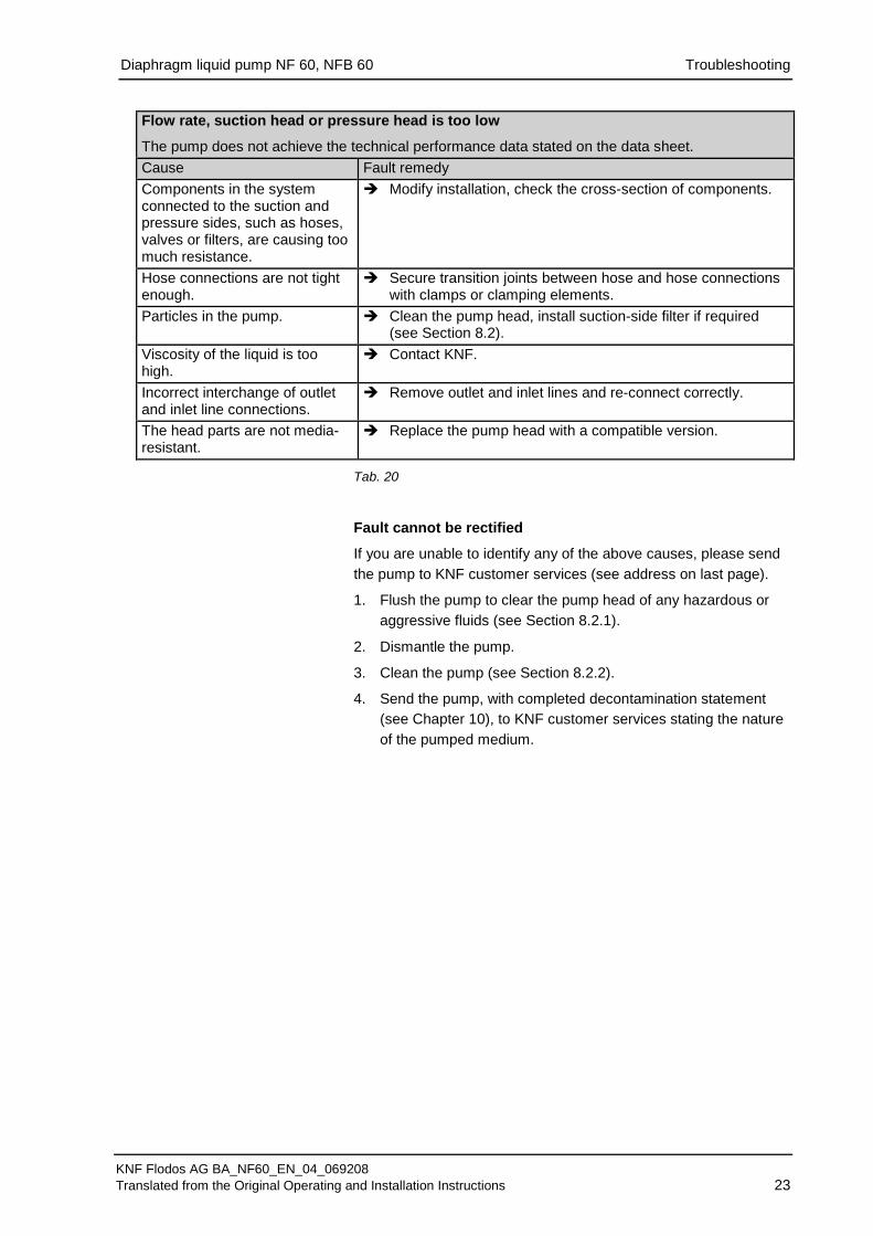
Flow rate, suction head or pressure head is too low
The pump does not achieve the technical performance data stated on the data sheet. Cause Fault remedy Components in the system connected to the suction and pressure sides, such as hoses, valves or filters, are causing too much resistance.
Modify installation, check the cross-section of components.
Hose connections are not tight enough.
Secure transition joints between hose and hose connections with clamps or clamping elements.
Particles in the pump. Clean the pump head, install suction-side filter if required (see Section 8.2).
Viscosity of the liquid is too high.
Contact KNF.
Incorrect interchange of outlet and inlet line connections.
Remove outlet and inlet lines and re-connect correctly.
The head parts are not media-resistant.
Replace the pump head with a compatible version.
Tab. 20
Fault cannot be rectified
If you are unable to identify any of the above causes, please send the pump to KNF customer services (see address on last page).
Flush the pump to clear the pump head of any hazardous or 1. aggressive fluids (see Section 8.2.1).
Dismantle the pump. 2.
Clean the pump (see Section 8.2.2). 3.
Send the pump, with completed decontamination statement 4. (see Chapter 10), to KNF customer services stating the nature of the pumped medium.
Diaphragm liquid pump NF 60, NFB 60 Decontamination declaration
KNF Flodos AG BA_NF60_EN_04_069208 Translated from the Original Operating and Installation Instructions 24
10. Decontamination declaration
KNF shall only undertake to repair the pump on condition that the customer provides certification of the transferred media and the cleaning of the pump (decontamination declaration).
In order to send a product back use the decontamination
declaration, which either was delivered with the product or is available on www.knf.com (Downloads).
Please fill in the pump type, serial number, pumped media and all other required information. Send the signed form together with the product to your KNF representative.

Diaphragm liquid pump NF 60, NFB 60 For your notes
KNF Flodos AG BA_NF60_EN_04_069208 Translated from the Original Operating and Installation Instructions 25

Diaphragm liquid pump NF 60, NFB 60 For your notes
KNF Flodos AG BA_NF60_EN_04_069208 Translated from the Original Operating and Installation Instructions 26
Diaphragm liquid pump NF 60, NFB 60 For your notes
KNF Flodos AG BA_NF60_EN_04_069208 Translated from the Original Operating and Installation Instructions 27

KNF worldwide
Please find your local KNF partners at: www.knf.com