development of a laser range finder for the antarctic plateau · proceedings of earsel-sig-workshop...
TRANSCRIPT
Proceedings of EARSeL-SIG-Workshop LIDAR, Dresden/FRG, June 16 – 17, 2000
EARSeL eProceedings No. 1 148
DEVELOPMENT OF A LASER RANGE FINDERFOR THE ANTARCTIC PLATEAU
L. Bartolini1, A. Bordone1, R. Fantoni1, M. Ferri de Collibus1, G. Fornetti1, C. Moriconi2, C. Poggi1
1. Division of Applied Physics, ENEA, C.R. Frascati, Rome, Italy, Tel: ++39-06-9400-5568, Fax:++39-06-9400-5312, Email: [email protected]
2. Division of Robotics and Informatics, ENEA, C.R. Casaccia, Rome, Italy, ++39-06-3048-6027,++39-06-3048-6038
ABSTRACTThe development of sensing subsystems is crucial to the operation of highly autonomous robots inharsh environments. This paper will describe the methodologies used and the preliminary measure-ment campaigns, with the relevant results obtained, which were carried out for the realisation of ahigh performance laser range finder. The sensor will be installed on an autonomous rover (RAS),lodged on a specially conditioned housing in front of the vehicle allowing for the greatest visibilityand optimum protection. The RAS will be used for scientific campaigns and logistic support opera-tions specifically in Antarctica and possibly in other snowy environments. Preliminary tests havebeen already carried out in Glaciers and Snow fields campaigns. A problem is the very poor S/Nratio in sunlight conditions, caused by the total backscattering of clean snow surface. Additionaldifficulties come from the behaviour of icy surfaces and from the poor transparency of the atmos-phere caused by wind-driven ice microcrystals. The technological solutions chosen to overcomethese aspects will be analysed.
INTRODUCTIONThe exploration of harsh environments, especially for wide area operations and measurement cam-paigns, is a reference field for highly autonomous robotics. The requirements of these applicationslead to the development of a wide spectrum of technologies with special emphasis on the sensingsubsystems, crucial point for a reliable world representation and thus for correct operation planningby the robot intelligence subsystem.
In harsh environments the availability of a sensor (intended as the total time of reliable operation)can be low and then the best solution is to achieve a good redundancy for each needed sense. Rangefinding is one of the crucial points for the robot operation, giving the distance and other informationbetween the mobile platform and the other objects of the scenario and has been achieved in the RAS(Robot for Antarctica Surface) project with three separate systems: stereo vision, millimetric waveradar, laser radar. The research project, funded by the Italian Ministry of Research in the frame ofthe PNRA (National Program for Researches in Antarctica) is well positioned from the point ofview of national and international co-operation. The activity is conducted in conjunction with CNES(Centre National d'Etudes Spatiales) and LAAS (Laboratory for Analysis and Architecture of Sys-tems) in the frame of the CONCORDIA initiative, the Italian and French Joint venture for the reali-sation of an international scientific base for the development of research activities in the interior ofthe Antarctica continent (in the site named DOME C). In particular CNES is interested in the devel-opment of autonomous or semiautonomous vehicles for planetary exploration, similar to the recentexperience of JPL (Jet Propulsion Laboratory, Pasadena) with the Rover Sojourner on Mars, and inthis respect the Antarctica site offers a number of significant conditions for testing the most criticaltechnologies. Again for space applications, ENEA (Italian National Committee for New Technology,Energy and Environment) is also exploring the possibility to coordinate a common experiment withthe Italian Space Agency (ASI) and other high technology operators like Tecnomare to test on the RASremote control techniques when long and very long communication delays occur.

Proceedings of EARSeL-SIG-Workshop LIDAR, Dresden/FRG, June 16 – 17, 2000
EARSeL eProceedings No. 1 149
RAS is a large robotics platform, built on a snowcat (Kässbohrer PB 260A, shown in picture 1)which is intended to support human operations in the Antarctic environment, ranging from theautomation of measurement campaigns to carrying out potentially dangerous tasks in logistics op-erations, for instance reconnaissance during traverses with man-driven vehicles. An autonomousvehicle has been recognised as a great safety improvement when travelling over crevassed surfacesin order to identify the best path for other vehicles. The project is therefore aimed at the study anddevelopment of the autonomy aspects and at the capability to make decisions relevant to the specifictasks assigned to the robot (typically navigation).
To achieve these aims the robot needs to operate on a robust world representation based on com-plete metrology information, reliable sensing of its own dynamic and kinematic data, semantic in-terpretation of the detected objects surrounding the vehicle, knowledge of meteorological conditions(the latter allowing to adequately weight the reliability of data coming from the different sensors),and to have an easy and stable communications subsystem. Starting from this information, a highlevel, rule based control system can be realised.
Picture 1: Antarctica traverse operation of Kässbohrer - RAS motion platform
This paper aims to present the problems encountered in icy environments with a laser sensor. ENEAworked for several years on the various techniques centred on the use of laser for range measuring.The most important problem to be faced within this experience is to cope with the extreme lightintensity of the Antarctic environment, partially, but not to the same extent, met also in glaciers athigher latitudes. This requirement, coupled with the need to ensure eye-safe operation, since thesemachines are also to operate in the presence of men, and a long-range operation (some tens of me-tres) represents a significant challenge for the realisation of the sensor itself. The final testing of thefully functional device is planned for the 2000-2001 winter campaign in the Arctic circle. The cam-paign in the final target environment, the Antarctic plateau, will be conducted one year later.
METHODSThe topological radar upon which the range finder is based is described briefly in this section to-gether with the relevant basic theory and the environmental characteristics peculiar to its use.
Topological radar: description and theoryHere a brief description of the demonstration unit, designed and developed in our laboratory, isgiven. The instrument consists of an incoherent diode laser sensor, suitable to be equipped with amechanical scanning camera. A modulated beam sounding technique is used for applications at

Proceedings of EARSeL-SIG-Workshop LIDAR, Dresden/FRG, June 16 – 17, 2000
EARSeL eProceedings No. 1 150
medium or low target distances, since the heterodyne technique employing a frequency down-conversion allows an indirect measurement of the round trip time delay of the sounding beamthrough a measurement of the phase delay of the signal photocurrent.
The transceiving component of the unit is shown in Figure 1. The telescope and the laser semicon-ductor are used in a monostatic configuration. The absolute range measurement is performed byusing a beam modulation technique carried out at 10 MHz frequency, so that unambiguous meas-urements can be obtained up to 15 m. Since the sensor should be able to operate in a wide range ofenvironmental conditions, a minimisation of the intense background light, expected during daylightoperation, is required on the receiving optics before reaching the detector. This has been obtained byintroducing a very narrow bandwidth interference filter (10 Å), combined with an iris which re-stricts the instantaneous field of view approximately to the dimensions of the beam spot on the re-mote target. A portion of the modulated laser beam is reflected by a beamsplitter and two prisms ona photodiode generating a sinusoidal signal with constant amplitude and phase. This acts as a refer-ence for the instantaneous phase measurement of the current signal coming from the detector. The
sinusoidal signal generated by thebeating of the reference and thesignal beam, which is detected bythe avalanche photodiode, has anamplitude depending on the reflec-tivity of the scene and a phase de-pending on the distance of the tar-get (1). The sensor can be operatedin combination with a mechanicalscanning camera, which sounds thescene with a raster of collimatedand focused modulated beam syn-chronised with an analogue todigital converter and acquisitionsystem.
Figure 1: The laser range finderlayout
An evaluation of the optical level available on the avalanche photodiode of the described transceivercan be carried out as follows: let PL be the power of the transmitted laser beam, R the distance of thetarget, ρ the overall target reflectance. Neglecting the power reflected in the mirror-like mode, weobtain (refer to Table 1 below for a full parameters definition) for the optical power on the detector:
Ps = PL ρ ε T D2 F(θ) e-2αR / 8R2 (1)
where F( θ ) = γ cos θ + ϕ S ( θ ) (2)
is the angular distribution of the backscattered signal, which adds to the cosine Lambertian distribu-tion a retroreflective component ϕS(θ) weakly dependent on θ when ϕ is near to the unity. Typicalpractical values valid for a large variety of target surfaces are listed in Table 1.
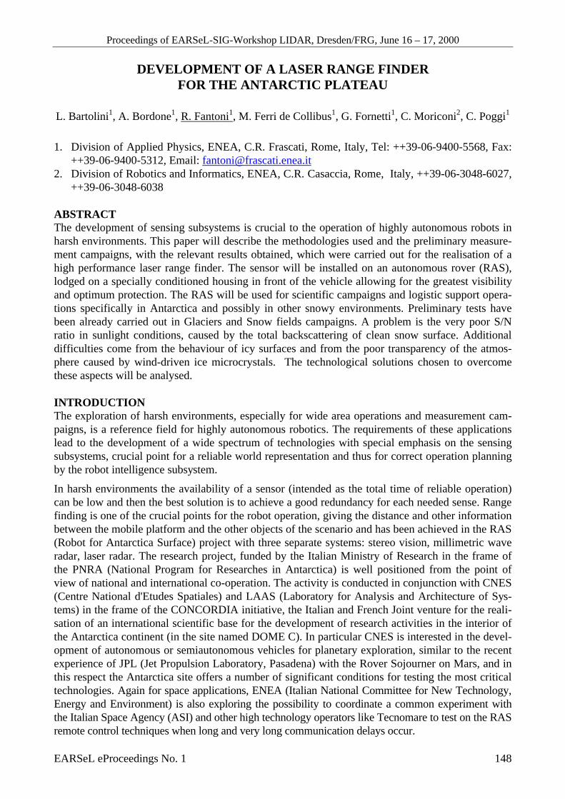
Table 1: Typical parameters for operation of a laser range finder
Optical wavelength λ = 670 nm
Proceedings of EARSeL-SIG-Workshop LIDAR, Dresden/FRG, June 16 – 17, 2000
EARSeL eProceedings No. 1 151
Transmitted laser power PL = 2 mWCarrier modulation depth M = 0.8Beam modulation frequency (Hz) f = ω/2π = 107
Distance from the target R = 1-15 mAtmospheric absorption coefficient α = 0.89 / kmIncidence angle of the soundingbeam
θ = 0°
Target average reflectivity ρ = 35 %Lambertian fractional power γ = 85 %Retroreflective fractional power S (θ) = 15 %Aperture of the receiving optics D = 0.05 mCollection efficiency of the receiver ε = 50 %Transmission of the interferencefilter
T = 60 %
Quantum efficiency of the detector η = 80 %Detector noise factor Γ = 1.5Pixel sampling time τ =10 ms
In order to determine the spatial resolution of a modulated laser sensor, the "phase noise" of themeasurement process must be accounted for. This consists of the uncertainty in the phase that origi-nates from a temporal jitter of the signal and can be evaluated as the inverse of the product of themodulation frequency, depth of modulation m and the current signal-to-noise ratio SNRi of the gen-erated current. The phase noise ∆R is then represented by the formula
∆R = c/(2mωSNRi) (3)
Assuming the arrival of the photons on the photocathode as a Poisson random process, and takinginto account only the shot noise of the signal, the current signal-to-noise ratio has the following ex-pression:
SNRi = (Psη τ /hν Γ )1/2 (4)
where h is Planck’s constant and ν is the optical frequency, τ = 1/2B and B is the bandwidth of thedetecting electronics; η represents the quantum efficiency and Γ is the noise factor associated withthe avalanche amplification process in the detector.
The scene backgroundDaylight operation of the designed scanning transceiver requires the use of several optical elementsto reduce as much as possible the level of stray light reaching the detector from the scene back-ground through the receiving optics. This is due to the scattered sunlight in the field of view (FOV)of the transceiver. The amount of spurious light can be estimated by evaluating the ratio of the sun-light transmitted by an interference filter with a wavelength bandwidth ∆λ and the total sunlightirradiance. Approximating the sun with a 6000°K blackbody radiator, this ratio is
r = F ∆λ (5)
where F is a form factor, which can be shown equal to F= 1.16 e-3 at the wavelength of 6328 Å. If amultilayer interference filter with ∆λ=10 Å is considered, and estimating in 0.13 W/cm2 the value ofthe total solar irradiance on the earth (2), the expected background level in the FOV of the receivingoptics is about 1.5 e-4 W/cm2 during daylight experiments.

Proceedings of EARSeL-SIG-Workshop LIDAR, Dresden/FRG, June 16 – 17, 2000
EARSeL eProceedings No. 1 152
In order to avoid excessive photon noise on thereceived signal, the contribution of the scene back-ground should be minimised by reducing the FOVof the receiving optics to values comparable withthe spot size of the transmitted beam on the target.In this case adaptive optics (3) can be inserted toadjust the position and the diameter of the iris onthe lens focus on the whole depth of field. Theseelements can be crucial to operate in severe straylight conditions; their proper design and test willbe the object of next laboratory investigations.
The compact arrangement designed for assemblingthe laser range finder inside the RAS is reported inFigure 2. Two sensors will be hosted on the sidesof a thermo-isolated compartment, together with amillimetric radar. For this purpose a large box wasbuilt on the front of the vehicle in place of thesnowbucket (approx. 1.5 m x 0.4 m x 0.3 m) andequipped with optical benches on anti-vibratingholdings.
Figure 2: Executive schematic of a single laserrange finder module for RAS
EXPERIMENTAL RESULTSIn order to match the sensor specifications for its optimised utilisation on RAS in an Antarcticenvironment, a series of measurements was carried out with the available modulated laser radarprototype (4), adapted to work in an external scenario under different daylight conditions. Resultswere compared to similar sets of laboratory measurements.
Hereafter the dc outdoor measurements (taken without any laser modulation) are reported, as theywere extremely useful to understand variations of the snow reflection coefficient during whole day,with different snow density and compactness. Furthermore ac indoor measurements (taken with thelaser modulation) were performed. During the laboratory experiment a strong light background wassimulated by means of an external 3400°K 1000 W lamp. From ac measurements, the receivedpower, the signal to noise ratio and the resolution in distance were estimated.
Outdoor reflectivity measurements were taken in the last year during test campaigns held at differ-ent sites characterised by the presence of snow and ice coupled to different meteorological condi-tions (sun irradiance, wind). Results reported here refer to Tonale glacier (Alps, June 1999), CampoFelice Snow field (Appennines, January 2000), the Arctic Base (Svalbard, March 2000) of CNR(Italian National Research Centre). Data taken on mountain places at intermediate latitudes corre-spond to high sun irradiance and strong variability of meteorological conditions with the suddenpassage of clouds, while in the polar region a constant sun illumination was met, with dominant
Proceedings of EARSeL-SIG-Workshop LIDAR, Dresden/FRG, June 16 – 17, 2000
EARSeL eProceedings No. 1 153
grazing incidence, and stable meteorological conditions. The latter situation might be quite similarto what characterises the Antarctic Plateau during the Austral summer.
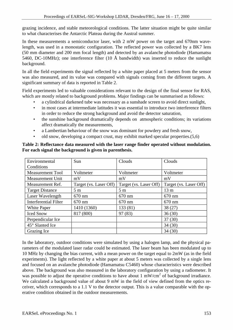
In these measurements a semiconductor laser, with 2 mW power on the target and 670nm wave-length, was used in a monostatic configuration. The reflected power was collected by a BK7 lens(50 mm diameter and 200 mm focal length) and detected by an avalanche photodiode (Hamamatsu5460, DC-10MHz); one interference filter (10 Å bandwidth) was inserted to reduce the sunlightbackground.
In all the field experiments the signal reflected by a white paper placed at 5 meters from the sensorwas also measured, and its value was compared with signals coming from the different targets. Asignificant summary of data is reported in Table 2.
Field experiments led to valuable considerations relevant to the design of the final sensor for RAS,which are mostly related to background problems. Major findings can be summarised as follows:
• a cylindrical darkened tube was necessary as a sunshade screen to avoid direct sunlight,• in most cases at intermediate latitudes it was essential to introduce two interference filters
in order to reduce the strong background and avoid the detector saturation,• the sunshine background dramatically depends on atmospheric conditions; its variations
affect dramatically the measurements,• a Lambertian behaviour of the snow was dominant for powdery and fresh snow,• old snow, developing a compact crust, may exhibit marked specular properties.(5,6)
Table 2: Reflectance data measured with the laser range finder operated without modulation.For each signal the background is given in parenthesis.
EnvironmentalConditions
Sun Clouds Clouds
Measurement Tool Voltmeter Voltmeter VoltmeterMeasurement Unit mV mV mVMeasurement Ref. Target (vs. Laser Off) Target (vs. Laser Off) Target (vs. Laser Off)Target Distance 5 m 5 m 13 mLaser Wavelength 670 nm 670 nm 670 nmInterferential Filter 670 nm 670 nm 670 nmWhite Paper 1410 (1360) 133 (81) 38 (27)Iced Snow 817 (800) 97 (83) 36 (30)Perpendicular Ice 37 (30)45° Slanted Ice 34 (30)Grazing Ice 34 (30)
In the laboratory, outdoor conditions were simulated by using a halogen lamp, and the physical pa-rameters of the modulated laser radar could be estimated. The laser beam has been modulated up to10 MHz by changing the bias current, with a mean power on the target equal to 2mW (as in the fieldexperiments). The light reflected by a white paper at about 5 meters was collected by a single lensand focused on an avalanche photodiode (Hamamatsu C5460) whose characteristics were describedabove. The background was also measured in the laboratory configuration by using a radiometer. Itwas possible to adjust the operative conditions to have about 1 mW/cm2 of background irradiance.We calculated a background value of about 9 mW in the field of view defined from the optics re-ceiver, which corresponds to a 1.1 V to the detector output. This is a value comparable with the op-erative condition obtained in the outdoor measurements.
Proceedings of EARSeL-SIG-Workshop LIDAR, Dresden/FRG, June 16 – 17, 2000
EARSeL eProceedings No. 1 154
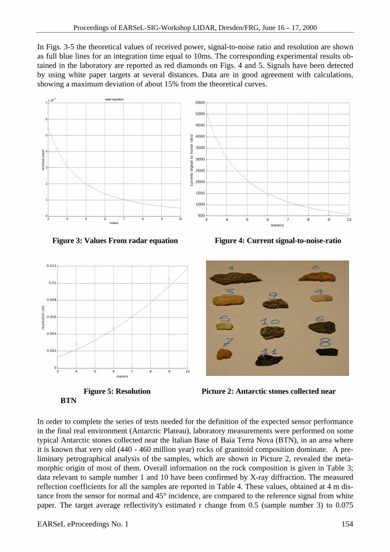
In Figs. 3-5 the theoretical values of received power, signal-to-noise ratio and resolution are shownas full blue lines for an integration time equal to 10ms. The corresponding experimental results ob-tained in the laboratory are reported as red diamonds on Figs. 4 and 5. Signals have been detectedby using white paper targets at several distances. Data are in good agreement with calculations,showing a maximum deviation of about 15% from the theoretical curves.
3 4 5 6 7 8 9 10
0
1
2
3
4
5
6
7x 10
-8
meters
rece
ived
pow
er
radar equation
3 4 5 6 7 8 9 10500
1000
1500
2000
2500
3000
3500
4000
4500
5000
5500
meters
curr
ent
sign
al t
o no
ise
ratio
Figure 3: Values From radar equation Figure 4: Current signal-to-noise-ratio
3 4 5 6 7 8 9 10
0
0.002
0.004
0.006
0.008
0.01
0.012
meters
reso
luti
on
(m
)
Figure 5: Resolution Picture 2: Antarctic stones collected nearBTN
In order to complete the series of tests needed for the definition of the expected sensor performancein the final real environment (Antarctic Plateau), laboratory measurements were performed on sometypical Antarctic stones collected near the Italian Base of Baia Terra Nova (BTN), in an area whereit is known that very old (440 - 460 million year) rocks of granitoid composition dominate. A pre-liminary petrographical analysis of the samples, which are shown in Picture 2, revealed the meta-morphic origin of most of them. Overall information on the rock composition is given in Table 3;data relevant to sample number 1 and 10 have been confirmed by X-ray diffraction. The measuredreflection coefficients for all the samples are reported in Table 4. These values, obtained at 4 m dis-tance from the sensor for normal and 45° incidence, are compared to the reference signal from whitepaper. The target average reflectivity's estimated r change from 0.5 (sample number 3) to 0.075

Proceedings of EARSeL-SIG-Workshop LIDAR, Dresden/FRG, June 16 – 17, 2000
EARSeL eProceedings No. 1 155
(sample number 8). Average values obtained for all samples, except the last one which is probably amore recent lavic fragment (about 10 million year old), are rather high for granite-like rocks. Thisfact is related to their richness in quartz, almost pure quartz crystals (sample n. 3,4,5) showing thehighest values, and to the presence of two high reflecting micas, the muscovite and the biotite,which appear as lighter and darker bright components respectively.
Table 3: Main constituents of different Antarctic stones collected nearby BTN station(January 1998).
Rock sample no. Assignment Average composition (remarks)1 metamorphic
metasedimentQuartz, feldspar, biotite.
2 granitoid Muscovite, quartz, rose feldspar.3,4,5 quartz Pure crystals (white and rose colours).6,9 two-micas
metasedimentBiotite, muscovite (probably different contents in Iron andCalcium).
7,10 pink granite Quarz, biotite, different feldspars, rutile (the pink colour isdue to K-feldspar).
8 Black lavic stone (porous, low specific weight).
Table 4: Reflection coefficients of samples listed in Table 3. Values refer to 90°/45° incidence.Measured background is 30 in all cases.
Target no.reference
white paper 1 2 3 4 5 6 7 8 9 10
Detectorvoltage (mV)
170/135
80/30
60/35
100/80
85/55
95/65
40/20
70/50
15/10
55/40
50/35
CONCLUSIONSRemotely Operated Vehicles like the Antarctic RAS (Robot for Antarctic Surface) robot ask for arobust, multi-equipment sensing system. These vehicles must be able to operate in environmentalconditions where one or more sensors cannot measure reliable data but some information still mustbe granted to the Supervisor to avoid the loss of the vehicle and/or the halting of the current opera-tion, sometimes crucial.
The multisensorial equipment of RAS includes stereo camera Artificial Vision, Laser radar, milli-metre waves radar, GPS (Geoplanetary Positioning System), GPR (Ground Penetrating Radar) and asuitable inertial system. Each one of these systems has been selected to be reliable in the referenceenvironment without high costs. This research aims to demonstrate the feasibility of the laser radarin environments where the noise generated by the extremely high intensity of the reflected sunlightcould heavily affect the reliability of measurements made.
The results up to now attained confirm the exploitability of this technique, the most precise avail-able in the whole equipment, together with the mm radar device, not yet fully tested. The currentobtained precision, that can be derived by Figure 5, is already satisfactory for the present applica-tion. This feature is expected to be substantially improved in the final device after optimising theoptical arrangement, the signal processing electronics and algorithms. At least a resolution of 1 cmat 30 m is expected following current laboratory tests.
Aspects that need further investigations refer to the scanning speed under different light conditions.Despite the presence of the stereo cameras, in some operative conditions, a scanning system is re-
Proceedings of EARSeL-SIG-Workshop LIDAR, Dresden/FRG, June 16 – 17, 2000
EARSeL eProceedings No. 1 156
quested also for the laser sensing equipment and the corresponding precision vs. the scanning speedin the snowy Antarctic plateau under all the different light conditions (different orientations of sen-sor vs. sunlight direction, foggy atmosphere, ice micro crystals under windy conditions) is impor-tant. The final equipment will be ready by the end of 2000 and the first tests on the Arctic field willbe carried out at the beginning of 2001.
ACKNOWLEDGEMENTSThe present work is supported by the PNRA (National Program for Research in Antarctica), underthe Technological Area project for RAS development.Dr. M. Angelone (ENEA-TEIN) and Dr. C. Crovato (ENEA-CAT) are to be thanked for the analysisof Antarctic rocks.
REFERENCES1. Nitzan, D., Brain, A.E. and Duda, R.O. 1977. The measurement and use of registered reflectance
and range data in scene analysis. Proc. IEEE, 65: 206-220.2. Shaw, J.H. 1962. Applied Optics, 1: 87.3. Bartolini, L. et al. 1990. A transceiver optical sensor for instantaneous distances measurements
with applications to large scenes profilometry. Presented at 23 International Symposium on Re-mote Sensing of Environment, Bangkok, April 18-25, 1990.
4. Bartolini, L. et al. 1993. Laser sensor for advanced robotic applications. PHE InternationalMeeting, Paris, July 1993.
5. Wolfe, W.L. and Zissis, G.J. 1989. The Infrared Handbook. Environmental Research Institute ofMichigan.
6. O’Brien, H.W. et al. 1975. Red and Near Infrared Spectral Reflectance of Snow. CREELHanover, NH, (AD-A007732).