destruction of voc in a dall energy biomass gasifier at ... · destruction of voc in a dall energy...
TRANSCRIPT

1
Destruction of VOC in a Dall Energy Biomass Gasifier at
Warwick Mills
Paper # 17
Presented at the
34th
International Conference on Thermal Treatment Technologies & Hazardous Waste
Combustors
October 20-22, 2015
Houston, TX
Authors:
Jens Dall Bentzen, Managing director Dall Energy,
Venlighedsvej 2, 2970 Hoersholm, Denmark.
E-mail: [email protected]
homepage: www.dallenergy.com
Charlie Howland, Managing director Warwick Mills, at 301 Turnpike Road, PO Box 409, New
Ipswich, NH. www.warwickmills.com
ABSTRACT
Warwick Mills, a factory in New Hampshire, which produces complex fiber composites for the
most challenging safety applications, has installed and commissioned a Dall Energy biomass
gasification plant.
The biomass plant has two main purposes:
- Destroy VOC from coaters in factory
- Produce steam to factory
On September 30 and October 1, 2014, the emissions of the biomass plant were measured.
Test September 30, 2014:
The VOC content in the combustion air was at maximum: 8,000-10,000 ppmv.
The VOC content in the stack was below 1 ppmv. The VOC destruction efficiency was 99.98 %.
Also the particulate content and the NOx in the flue gas were measured:The particulate content
was below 10 mg/Nm3. The NOx was below 60 mg/Nm3 (30 ppmv).
Test October 1, 2014
The VOC content in the combustion air at medium: approximately 3,000 ppmv.
The VOC content in the stack was below 3 ppmv. The VOC destruction efficiency was 99.8 %.

2
Also the NOx in the flue gas was measured. The NOx was below 80 mg/Nm3 (40 ppmv).
The VOC content in ambient air, outside the stack, was about 5-10 ppmv, thus higher than inside
the stack.
INTRODUCTION
A new type of biomass and waste combustion system has been developed and implemented in 3
full scale projects: 2 in Denmark and 1 in USA.
The purpose was to develop a combustion system that:
- Can use multiple types of fuels
- Has low emissions
- Can modulate
The purpose of the technology is to produce thermal energy for communities and industries using
low grade solid fuels (MSW, wood wastes). Further,the technology can be used for incineration
of industrial wastes and destruction of VOC.
This paper describe the history of the development of the technology, with focus on the plant at
Warwick Mills in New Hampshire, USA.
The idea behind the development was to take advantage of the benefits within updraft
gasification technology in a combustion system. Updraft gasification is an old, well known
technology which has been used to produce town gas for centuries.
However, updraft gasification has some disadvantages: When the gas is cooled, a large amount
of tars condense, thus plugging up pipes and polluting waste water from the gas condensation
system.
The updraft gasification technology
With updraft gasification, the gasification medium (air/steam) and the produced gas flow
through the gasification reactor in the opposite direction to the fuel bed. The
reactor is fed from above, and the gasification media enters the reactor in the bottom.
With this method of gasification, clearly defined reaction zones arise in the bulk filling. The
sensitive heat of the produced raw gas is used to dry the fuel and to initiate pyrolysis.

3
Figure 1. Schematic diagram of an updraft gasifier [2]
As it can be seen in the schematic diagram in Figure 1, the products of decomposition
released in the pyrolysis zone and the steam released as a result of fuel drying
are discharged directly out of the reactor with the producer gas. The tars that are produced in the
pyrolysis zone are not conducted through any hot zone and can therefore not be suitably split up
or oxidized. The tar content in the raw gas can thus reach values over 100 g/Nm3.
The Bioneer updraft gasification system
During the 1980’s the Finnish company Bioneer made 9 commercial district heating systems,
where an updraft gasifier produced gas for use in a gas boiler. The fuels were wood chips and
peat. The plants operated fine, but tars did foul the gas pipe leading from the gasifier into the
boiler. In some plants the gas line was cleaned once every 2-6 weeks (depending on the fuel
properties and output of the gasifier). [1]

4
Figure 2. Bioneer-gasifier in the district heating plant of Kauhajoki, Finland [1]
The Babcock&Wilcox Vølund gasification system
During the 1990’s the Danish company Babcock&Wilcox Vølund (BWV) develop a gasification
system for combined heat and power, based on updraft gasification technology.
In the BWV system, the gas is cooled and cleaned and thereafter used in an internal combustion
engine for production of heat and power.
A demonstration plant was built in the Danish town Harboøre, and after a few years the plant
was placed in commercial operation. In the BWV concept, the gas is cooled in a wet cyclone and
wet electrostatic precipitator after the gasifier. There are no problems with fouling of gas pipes,
but the large amounts of tar are dissolved in the scrubber water.
The main technical and financial issue about this technology is the rather complex gas cleaning
and waste water cleaning systems which handle the considerable amounts of tar.

5
Figure 3. BWV gasifier (left) and flow diagram at heat and power plant Harboøre (right) [3]
The Dall Energy gasification and gas combustion concept
Previous attempts to make commercial concepts by use of the updraft gasification technology
had problems with the high amounts of tars that are produced in the updraft gasifier.
The idea behind the Dall Energy concept is to burn the tar producing gases produced in the
gasifier above the gasification section in the same reactor as where the gasification takes place.
Hereby, the advantages of the updraft technology will be maintained, while the disadvantage of
tar in the gas will be solved.
Figure 4. Principle diagram of Dall Energy multifuel furnace. [5]
6
THE DEVELOPMENT AND IMPLEMENTATION OF THE DALL
TECHNOLOGY
2 MW Pilot plant
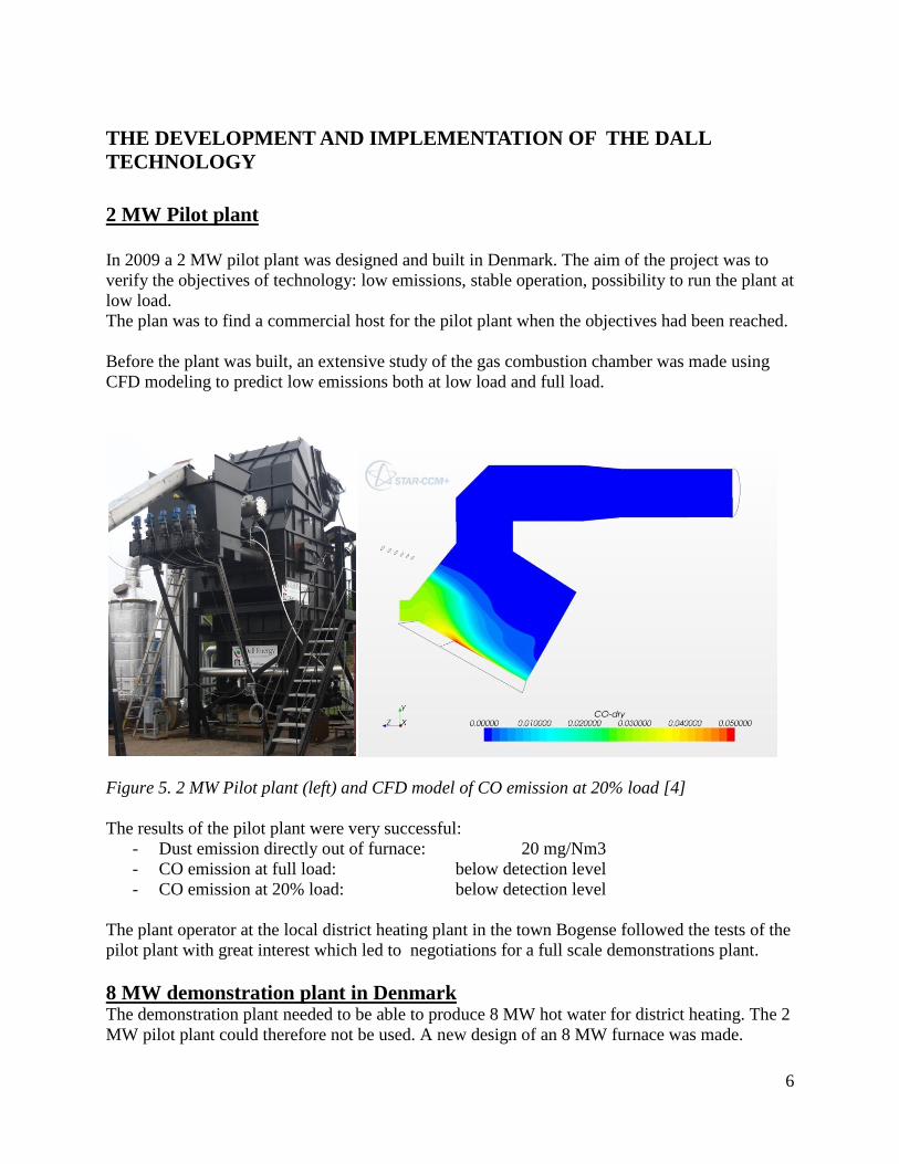
In 2009 a 2 MW pilot plant was designed and built in Denmark. The aim of the project was to
verify the objectives of technology: low emissions, stable operation, possibility to run the plant at
low load.
The plan was to find a commercial host for the pilot plant when the objectives had been reached.
Before the plant was built, an extensive study of the gas combustion chamber was made using
CFD modeling to predict low emissions both at low load and full load.
Figure 5. 2 MW Pilot plant (left) and CFD model of CO emission at 20% load [4]
The results of the pilot plant were very successful:
- Dust emission directly out of furnace: 20 mg/Nm3
- CO emission at full load: below detection level
- CO emission at 20% load: below detection level
The plant operator at the local district heating plant in the town Bogense followed the tests of the
pilot plant with great interest which led to negotiations for a full scale demonstrations plant.
8 MW demonstration plant in Denmark The demonstration plant needed to be able to produce 8 MW hot water for district heating. The 2
MW pilot plant could therefore not be used. A new design of an 8 MW furnace was made.

7
A contract between Bogense district heating company and the contractor, Weiss A/S, was made
in May 2010. Dall Energy had the task to design the furnace and administrate a grant from the
EUDP program.
The Bogense plant was placed in un-manned, commercial operation in 2012. [6]
Various types of fuels are used in the plant including garden wastes and wood wastes.
Figure 6. 8 MW Demonstration plant in Bogense [4]
Emission tests was made in marts 2012
Table 1. Measurements in flue gas directly out of furnace Parameter Unit Average Average
Load % 100 20
Date dd-mm-yy 20-03-2012 20-03-2012
Measuring period hh:mm 11:12 - 14:22 16:44 - 20:00
Temperature °C 958 845
O2 Vol % (dry) 4.88 5.25
H2O Vol % 38.0 32.4
CO mg/m³(ref) < 2 < 2
NOX mg/m³(s,d) 300 200
NOX mg/m³(ref) 200 140
Particles * mg/m³(s,d) 100 92
Particles * mg/m³(ref) 69 64
Condensable in rinse and condensate mg/m³(s,d) 73 97
Condensable in rinse and condensate mg/m³(ref) 50 68
(s,d) indicates dry gas at standard conditions (0°C, 101,3 kPa) (ref) indicates dry gas at standard conditions (0°C, 101,3 kPa) at 10 % O2
* means "not included in accreditation no. 51"
8
2 MW plant for VOC destruction at Warwick Mills
Warwick Mills, New Hamphire, USA is a leader in the engineering of technical textiles for
protective applications. Warwick Mills develops and manufactures complex fiber composites for
the most challenging safety applications.
The advanced manufacturing of safety equipment includes coating of wowen materials with
organic solvents. The ventilation air from the coaters contains Volatile Organic Compounds
(VOC) which needs to be combusted in a thermal oxidizer before the ventilation air can be sent
to the stack.
The fuel bill for the oil based thermal oxidizer was constantly increasing, and the plant manager,
Charlie Howland, started in 2008 to search for biomass technology which could be used instead
of oil. The biomass plant needed to fulfill the strict emission regulations of New Hampshire.
Mr. Howland could not find a biomass technology locally that could fulfill the emission
regulations. In 2010 Mr. Howland made some search via “Google” and found hereby the web
site of Dall Energy, who had published the results of the pilot plant.
Mr. Howland decided to visit Dall Energy in January 2011 to see the pilot plant and the Bogense
plant which at that time was under construction.
Dall Energy and Warwick Mills made thereafter an agreement for the design and build of a
biomass plant for Warwick Mills which would have several purposes:
- Destruction of VOC.
- Production of Steam.
- Control strategy of the plant so destruction of VOC was independent of steam production
- Low load for “stand by” during weekend
- Low particle load in chimney.
During 2011-2012 the building permits were obtained and construction of the plant could start.
The production of the furnace was now ready to start. The size of the plant for Warwick Mills
was the same as the pilot plant built in 2010; and as the pilot plant was no longer in use, Dall
Energy-Warwick agreed that Warwick Mills could buy the pilot plant.
And so the pilot plant was dismantled and shipped from Denmark to USA.
The first start up of the plant was done in April 2014. During the first week of operation, various
points were located to be optimized and adjusted. The plant was shut down and the list of
adjustments was made.
The plant was started up again in June 2014 and has been in operation since then.

9
Figure 7 Principle diagram of Dall Energy Furnace at Warwick Mills.
Emission test
The plant is used for destruction of organic solvents in the ventilation air (VOC). It was written
into the permit that an emission test was required at least 6 month after starting the plant. The
emission test must verify that the VOC destruction efficiency was at least 98% and particulates
in the flue gas had to be below 40 mg/Nm3.
The stack test was scheduled for two days: September 30 and October 1 2014.
Test September 30, 2014:
The VOC content in the combustion air was at maximum: 10.000 ppmv.
The VOC content in the stack was below 1 ppmv.
The VOC destruction efficiency was 99.98%.
Also the particulate content and the NOx in the flue gas was measured.
The particle content was below 10 mg/Nm3.
The NOx was below 60 mg/Nm3. (30 ppmv)
Test October 1, 2014
The VOC content in the combustion air was approximately 3000 ppmv.
The VOC content in the stack was below 3 ppmv.
The VOC destruction efficiency was 99.8%.

10
Also the NOx in the flue gas was measured.
The NOx was below 80 mg/Nm3. (40 ppmv).
Less emission in stack than in ambient air
Ambient air contained VOC from various sources such as degradation of wood in forest, traffic,
chimneys, etc.
The VOC content in ambient air, outside the stack, was about 5-10 ppmv, thus higher than inside
the stack.
Figure 8 Emission test. Warwick Mills, 2014.
Figure 9 Filters after emission test. Warwick Mills, 2014.

11
Operating strategies of the plant
The biomass plant at Warwick Mills has two main purposes:
- Destroy VOC from factory
- Produce steam to the factory
The amount of VOC-loaded air and the need for steam are not related so a new strategy of
operating the plant was developed:
Demand Operating strategies
High Energy demand Increase of primary air until energy demand
fulfilled.
High VOC destruction demand Increase of (VOC loaded) tertiary air
Idle load during weekends
The factory is normally shut down during weekends. An operating strategy for “low chip
consumption” was developed so the plant can keep warm during weekends and only use a very
low amount of wood chips.
On Monday morning the plant can go from “weekend mode” to “full load” in few hours.
.
Figure 10 Gasification plant operator, Marcel Alex, (left) and Managing director Charlie
Howland (right) at the Gasifier, June 2015.
A film about the plant can be viewed here: https://www.youtube.com/watch?v=LcBN7xeCOYA

12
9 MW plant in Denmark
During 2013-2014, a new 9 MW plant was planned and built in Denmark.
The client is Sønderborg district heating company. The purpose of this plant is to supply cheap
and renewable heat to the Sønderborg district.
The plant was started up in January 2015. Emission tests were carried out in March 2015. The
low emissions of the pilot plant, the Bogense plant and the Warwick plant were verified.
Figure 11 Emissions of NOx, CO and Dust from three Dall Energy plants.
0
100
200
300
400
500
600
700
NOx CO Dust
mg/
Nm
3
Emissions from Dall Energy plants
Danish Limits
Bogense
Sønderborg
Warwick

13
Figure 12 9 MW Dall Energy plant in Sønderborg.
RESULTS AND DISCUSSION
A new, multi-fuel, low emission combustion system has been developed.
The technology has been verified in a pilot plant and 3 commercial plants: 2 district heating
plants in Denmark for production of hot water and 1 industrial plant for VOC destruction and
production of steam in USA.
During the projects, the following features have been verified:
- 99.8%-99.98% VOC destruction
- 20-70 mg/Nm3 dust directly out of Furnace
- Fuel flexibility:
- Garden waste, wood waste, wood chips.
- 20-60 % moisture content
- 1-5% ash content
- 10-100 % operating load.
- Stable operation.
ACKNOWLEDGEMENTS
EUDP – The Danish Energy Agency support program who have contributed with financial
support
The Growth fund who have contributed with financial support
The Danish Environmental Agency who have contributed with financial support
The Ministry for Research and Innovation who have contributed with financial support

14
REFERENCES
1. OPET Finland, Review of Finnish gasification technologies, OPET Report 4, ESPOO 2002
2. Gasification Guide, Deliverable 8: Biomass gasification – State of the art description.
December 2007.
3. Biomass gasification plants. From web page of Vølund: www.volund.dk
4. Verification and further development of multifuel furnace for biomasse with low NOx and
dust emissions. Danish Energy Agency.
5. Dall Energy homepage www.dallenergy.com
6. Research in Bioenergy, September 2013. http://www.biopress.dk/forside
KEYWORDS
Biomass, multifuel, gasification, VOC, Emissions, NOx, CO, Dust. Environmental