gasifier design
TRANSCRIPT
8/6/2019 Gasifier Design
http://slidepdf.com/reader/full/gasifier-design 1/139
8/6/2019 Gasifier Design
http://slidepdf.com/reader/full/gasifier-design 2/139
Wood gas as engine fuel
Mechanical Wood Products BranchForest Industries DivisionFAO Forestry Department
The designations employed and the presentation of material in this publication do not implythe expression of any opinion whatsoever on the part of the Food and Agriculture
Organization of the United Nations concerning the legal status of any country, territory, city or area or of its authorities, or concerning the delimitation of its frontiers or boundaries.
M-38ISBN 92-5-102436-7
All rights reserved. No part of this publication may be reproduced, stored in a retrievalsystem, or transmitted in any form or by any means, electronic, mechanical, photocopying or otherwise, without the prior permission of the copyright owner. Applications for suchpermission, with a statement of the purpose and extent of the reproduction, should beaddressed to the Director, Publications Division, Food and Agriculture Organization of theUnited Nations, Via delle Terme di Caracalla, 00100 Rome, Italy.
© FAO 1986
This electronic document has been scanned using optical character recognition (OCR)software and careful manual recorrection. Even if the quality of digitalisation is high, the FAOdeclines all responsibility for any discrepancies that may exist between the present document and its original printed version.
Table of Contents
Preface
Chapter 1 - Introduction
1.1 Background1.2 The present case for wood gasifiers1.3 Overview of the contents of this publication1.4 What to expect from a wood gasifier system
8/6/2019 Gasifier Design
http://slidepdf.com/reader/full/gasifier-design 3/139
Chapter 2 - Small wood and charcoal gasifiers for operation of internal combustionengines
2.1 Fuelling of engines by producer gas
2.1.1 Possibilities of using producer gas with different types of engines2.1.2 Engine power output using producer gas2.1.3 Maximizing the power output in producer-gas operation2.1.4 Resulting power output2.1.5 Gas quality requirements for trouble-free operation2.1.6 Use of Stirling engines or gas turbines with producer gas
2.2 Theory of gasification
2.2.1 Prediction of the gas composition2.2.2 Gasifier efficiency
2.3 Types of gasifiers
2.3.1 Updraught or counter current gasifier 2.3.2 Downdraught or co-current gasifiers2.3.3. Cross-draught gasifier 2.3.4. Fluidized bed gasifier 2.3.5 Other types of gasifiers
2.4 Gasification fuels
2.4.1 Need for selection of the right gasifier for each fuel
2.4.2 Energy content of the fuel2.4.3 Moisture content of the fuel2.4.4 Volatile matter content of the fuel2.4.5 Ash content and ash chemical composition2.4.6 Reactivity of the fuel2.4.7 Particle size and size distribution2.4.8 Bulk density of the fuel2.4.9 Charring properties of the fuel2.4.10 Assessment of the suitability of various types of biomass as gasifier fuel
2.5 Design of downdraught gasifiers
2.5.1 Processes occurring in the down-draught gasifier 2.5.2 Design guidelines for downdraught gasifiers
2.6 Gas cleaning and cooling
2.6.1 Cleaning dust from the gas2.6.2 Gas cooling
2.7 Applications of biomass gasification
2.7.1 Production of fuel gas
2.7.2 Production of mechanical or electrical power in stationary installations2.7.3 Mobile applications
8/6/2019 Gasifier Design
http://slidepdf.com/reader/full/gasifier-design 4/139
2.8 Health and environmental hazards associated with the use of producer gas
2.8.1 Toxic hazards2.8.2 Fire hazards2.8.3 Explosion hazards2.8.4 Environmental hazards
Chapter 3 - Recent Swedish experiences with operation of vehicles on wood andcharcoal gas
3.1 Overview of development work and testing carried out at the national machinerytesting institute
3.1.1 Scope of the work3.1.2 Gasifier for wood chips3.1.3 Fibre glass fabric filter system3.1.4 Conversion of diesel engines to producer gas operation
3.1.5 Tests with different fuels
3.2 Experiences gained from conversion and operation of modern vehicles
3.2.1 The need for continued practical tests3.2.2 Conversion and operation of a Massey Ferguson 1100 farm tractor 3.2.3 Conversion and operation of a Scania truck3.2.4 Experiences related to service, maintenance and equipment failures
3.3 Producer gas vehicles recently operated in other countries
3.4 Economic evaluation of operation of vehicles on wood gas
3.4.1 The case for wood gasifiers3.4.2 Method used for the economic evaluation3.4.3 Economic baseline assumptions3.4.4 Marginal costs for the wood gasifier system3.4.5 Economy of a producer gas tractor 3.4.6 Economy of a producer gas truck
3.5 Feasibility of using the vehicle gasifier technology for stationary applications
3.6 Operating hazards
Chapter 4 - A small wood gas power plant at a sawmill in Paraguay
4.1 Description of the wood gas power plant
4.1.1 Fuel supply4.1.2 The wood gasifier 4.1.3 Wood gas cooling and washing installations4.1.4 Wood gas filter 4.1.5 Engine and electric generator
4.2 Operating experience
8/6/2019 Gasifier Design
http://slidepdf.com/reader/full/gasifier-design 5/139
4.2.1 Fuel consumption4.2.2 Manpower employed and operating procedure4.2.3 Safety4.2.4 Environmental impact
4.3 Economic evaluation
4.3.1 Capital investment4.3.2 Operation and maintenance costs4.3.3 Fuel costs4.3.4 Total operating costs4.3.5 Costs for electricity generation for family homes of sawmill personnel4.3.6 Comparison with other alternatives for the electricity supply
Chapter 5 - A small gasifier power plant in Sri Lanka
5.1 Description of the plant
5.1.1 General system layout5.1.2 The gasifier 5.1.3 Cyclone5.1.4 Impingement separator 5.1.5 Glass fibre cloth filter 5.1.6 Cooler 5.1.7 Engine and alternator 5.1.8 Start-up fan and flare5.1.9 Safety devices5.1.10 Auxiliaries
5.2 Operational procedures
5.2.1 Start-up5.2.2 Closing down5.2.3 System maintenance
5.3 Operational experience
5.3.1 Operating record and observations on the performance5.3.2 Disturbances of the operation5.3.3 Desirable modifications
5.4 Economic evaluation of electricity generation costs at Giriulla mill
5.5 Concluding remarks
Chapter 6 - A 1.4 MW wood gas fuelled power plant in Paraguay
6.1 Historical background of the gasifier installations6.2 Wood-fuel supply and preparation6.3 Description of the down-draught gasifiers6.4 Electricity production with the gas engine alternator sets
6.5 Operating experiences6.6 Profitability of using wood gas at Loma Plata
8/6/2019 Gasifier Design
http://slidepdf.com/reader/full/gasifier-design 6/139
Chapter 7 - The future of wood gas as engine fuel
7.1 Prerequisites for extensive use of wood gasifiers7.2 Industrialized countries7.3 Developing countries7.4 The need for international cooperation
Appendix 1 - Calculation of the power output of a producer gas engine
Appendix 2 - Design calculation of downdraught gasifier
Table of conversion factors and symbols (used in this manual)
References

8/6/2019 Gasifier Design
http://slidepdf.com/reader/full/gasifier-design 7/139
Preface
Wood gasifiers played an important role in the past in the substitution of oil-based fuels ininternal combustion engines, but fell into disuse after the Second World War because of their economic and technical disadvantages as compared with relatively inexpensive imported
fuels.
Since the middle of the 1970's the increase in oil prices has led to a renewed interest in woodgasification technology, especially in countries dependent on oil imports but with adequatesupplies of wood or other biomass fuels or, as in the case of Sweden, where the technologyis maintained and developed as a matter of policy.
Research into the technology of gasifier/engine systems has provided modern designs whichwork reliably at a level of technical skill appropriate to rural applications in developingcountries. Such systems are economic in certain conditions found in many developingcountries, but the technology and manufacturing facilities are not widely available and their commercial utilisation is limited.
In "Wood Gas as Engine Fuel" FAO presents a summary of modern wood gasificationtechnology and the economics of its application to internal combustion engines. Texts ondifferent aspects of wood gasification, prepared by specialists, are the basis of thispublication.
FAO gratefully acknowledges the co-operation of B. Kjellström of the Beijer Institute,Stockholm; H. Stassen of the Twente University of Technology, Enschede, Netherlands; D.de Silva of the Ceylong Institute of Scientific and Industrial Research; N.E. Cañete of theSociedad Cooperativa Chortitzer Komitee, Paraguay and R. Thun of the Technical ResearchCentre of Finland.
1
8/6/2019 Gasifier Design
http://slidepdf.com/reader/full/gasifier-design 8/139
1.1 Background
Coal, wood and charcoal gasifiers have been used for operation of internal combustionengines in various applications since the beginning of this century. The utilization peakedduring the Second World War when almost a million gasifiers were used all over the world,
mainly vehicles operating on domestic solid fuels instead of gasoline.
It is important to keep in mind that small gasifiers have been used quite extensively in thepast and that they have played a very important part in reducing or eliminating the need for fuel imports in some countries. There is no need, however, in this publication to go deeper into the history of the development of small gasifier technology. Those who are interested inthe subject are advised to study the reviews made by the Swedish Academy of EngineeringSciences (43) Kaupp and Goss (20) Skov (36) Bailey (3) Earthscan (12) or the National Academy of Sciences in U.S.A. (32).
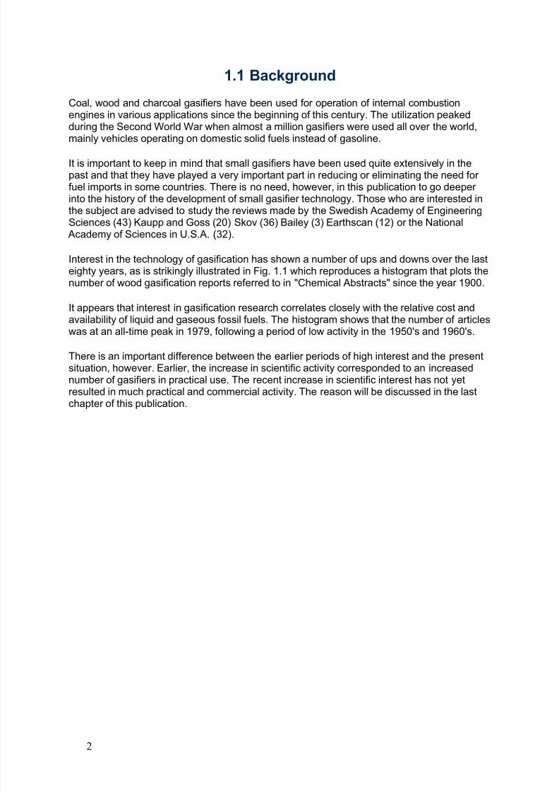
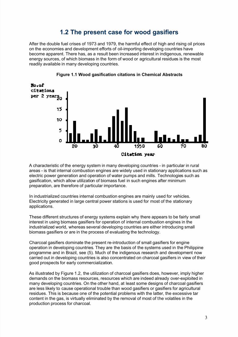
Interest in the technology of gasification has shown a number of ups and downs over the lasteighty years, as is strikingly illustrated in Fig. 1.1 which reproduces a histogram that plots thenumber of wood gasification reports referred to in "Chemical Abstracts" since the year 1900.
It appears that interest in gasification research correlates closely with the relative cost andavailability of liquid and gaseous fossil fuels. The histogram shows that the number of articleswas at an all-time peak in 1979, following a period of low activity in the 1950's and 1960's.
There is an important difference between the earlier periods of high interest and the presentsituation, however. Earlier, the increase in scientific activity corresponded to an increasednumber of gasifiers in practical use. The recent increase in scientific interest has not yetresulted in much practical and commercial activity. The reason will be discussed in the lastchapter of this publication.
2
8/6/2019 Gasifier Design
http://slidepdf.com/reader/full/gasifier-design 9/139
1.2 The present case for wood gasifiers
After the double fuel crises of 1973 and 1979, the harmful effect of high and rising oil priceson the economies and development efforts of oil-importing developing countries havebecome apparent. There has, as a result been increased interest in indigenous, renewable
energy sources, of which biomass in the form of wood or agricultural residues is the mostreadily available in many developing countries.
Figure 1.1 Wood gasification citations in Chemical Abstracts
A characteristic of the energy system in many developing countries - in particular in ruralareas - is that internal combustion engines are widely used in stationary applications such as
electric power generation and operation of water pumps and mills. Technologies such asgasification, which allow utilization of biomass fuel in such engines after minimumpreparation, are therefore of particular importance.
In industrialized countries internal combustion engines are mainly used for vehicles.Electricity generated in large central power stations is used for most of the stationaryapplications.
These different structures of energy systems explain why there appears to be fairly smallinterest in using biomass gasifiers for operation of internal combustion engines in theindustrialized world, whereas several developing countries are either introducing smallbiomass gasifiers or are in the process of evaluating the technology.
Charcoal gasifiers dominate the present re-introduction of small gasifiers for engineoperation in developing countries. They are the basis of the systems used in the Philippineprogramme and in Brazil, see (5). Much of the indigenous research and development nowcarried out in developing countries is also concentrated on charcoal gasifiers in view of their good prospects for early commercialization.
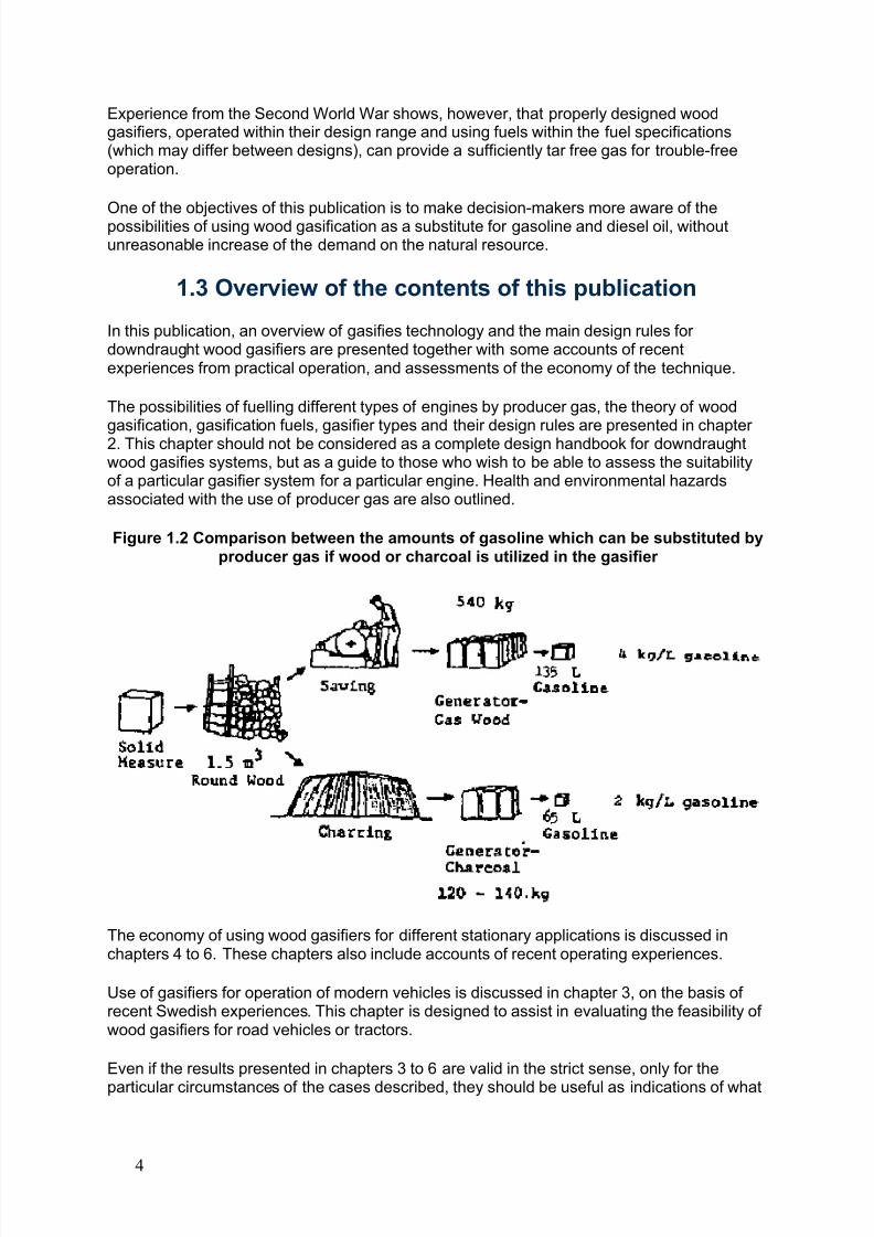
As illustrated by Figure 1.2, the utilization of charcoal gasifiers does, however, imply higher demands on the biomass resources, resources which are indeed already over-exploited inmany developing countries. On the other hand, at least some designs of charcoal gasifiersare less likely to cause operational trouble than wood gasifiers or gasifiers for agricultural
residues. This is because one of the potential problems with the latter, the excessive tar content in the gas, is virtually eliminated by the removal of most of the volatiles in theproduction process for charcoal.
3
8/6/2019 Gasifier Design
http://slidepdf.com/reader/full/gasifier-design 10/139
Experience from the Second World War shows, however, that properly designed woodgasifiers, operated within their design range and using fuels within the fuel specifications(which may differ between designs), can provide a sufficiently tar free gas for trouble-freeoperation.
One of the objectives of this publication is to make decision-makers more aware of thepossibilities of using wood gasification as a substitute for gasoline and diesel oil, withoutunreasonable increase of the demand on the natural resource.
1.3 Overview of the contents of this publication
In this publication, an overview of gasifies technology and the main design rules for downdraught wood gasifiers are presented together with some accounts of recentexperiences from practical operation, and assessments of the economy of the technique.
The possibilities of fuelling different types of engines by producer gas, the theory of wood
gasification, gasification fuels, gasifier types and their design rules are presented in chapter 2. This chapter should not be considered as a complete design handbook for downdraughtwood gasifies systems, but as a guide to those who wish to be able to assess the suitabilityof a particular gasifier system for a particular engine. Health and environmental hazardsassociated with the use of producer gas are also outlined.
Figure 1.2 Comparison between the amounts of gasoline which can be substituted byproducer gas if wood or charcoal is utilized in the gasifier
The economy of using wood gasifiers for different stationary applications is discussed inchapters 4 to 6. These chapters also include accounts of recent operating experiences.
Use of gasifiers for operation of modern vehicles is discussed in chapter 3, on the basis of recent Swedish experiences. This chapter is designed to assist in evaluating the feasibility of wood gasifiers for road vehicles or tractors.
Even if the results presented in chapters 3 to 6 are valid in the strict sense, only for the
particular circumstances of the cases described, they should be useful as indications of what
4
8/6/2019 Gasifier Design
http://slidepdf.com/reader/full/gasifier-design 11/139
can be expected in similar situations. The information can be adapted for applications wherethe operating conditions or the economic circumstances are different.
The future of wood gas as engine fuel is discussed in the final chapter where the need for continued international cooperation in this field is also emphasized.
1.4 What to expect from a wood gasifier system
Operation of modern spark ignition or compression ignition stationary engines with gasolineor diesel fuel is generally characterized by high reliability and minor efforts from the operator.Under normal circumstances the operator's role is limited to refuelling and maintenance.There is little need for action and virtually no risk of getting dirty. Start and operation can infact be made fully automatic.
Anybody expecting something similar for wood gas operation of engines will be disappointed.Preparation of the system for starting can require half an hour or more. The fuel is bulky and
difficult to handle. Frequent feeding of fuel is often required and this limits the time the enginecan run unattended. Taking care of residues such as ashes, soot and tarry condensates istime-consuming and dirty.
It is a common mistake to assume that any type of biomass which fits into the opening of therefuelling lid can be used as fuel. Many of the operational difficulties which faceinexperienced users of gasifiers are caused by the use of unsuitable fuels. In order to avoidbridging in the fuel bunker, reduced power output because of large pressure losses, or "weak" gas, slag cakes, tar in the engine and damage to the gasifier caused by overheating,it is necessary for most designs that the fuel properties are kept within fairly narrow ranges.This is not necessarily a more serious limitation than the need to use gasoline of super gradefor high compression spark ignition engines rather than regular gasoline or diesel fuel. But in
the case of gasifier operation, more of the responsibility for quality control of the fuel restswith the operator. The need for strict fuel specifications is well documented in theexperiences reported from the Second World War (43). It is unfortunate that somecommercial companies, with little practical experience, but trying to profit from the renewedinterest in gasification, have advertised the possibility of using almost any kind of biomasseven in gasifiers which will work well only with fuels meeting fairly strict standards. This hasin some cases created unrealistic expectations and has led to disappointments with thetechnology.
Operation of wood gas engines can also be dangerous if the operator violates the safetyrules or neglects the maintenance of the system. Poisoning accidents, explosions and fireshave been caused by unsafe designs or careless handling of the equipment. It may be
assumed that modern systems are designed according to the best safety standards, but it isstill necessary to handle the equipment in a responsible manner.
Finally, it must be realised that the current technology is generally based on the designs of the mid-1940's. Only a few persons have retained detailed practical knowledge of design,material selection and operation and maintenance procedures. Many of the currently activemanufacturers have no access to the experience of such persons and base their designs oninformation available in the literature, and on recent and comparatively limited experience.There has been some improvement of the technology, for instance of filter designs based onnew materials, but the practical operating experience with these improved systems is limited. A consequence of this is that equipment failures caused by design mistakes, choice of the
wrong materials, or incomplete instructions to the user on operation and maintenance, mustbe expected in the first period of reintroduction of wood gasifiers.
5

8/6/2019 Gasifier Design
http://slidepdf.com/reader/full/gasifier-design 12/139
The reports on operational difficulties presented in this publication and elsewhere must beevaluated with this in mind. It can safely be assumed that second generation systems willshow improved performance.
Those interested in the technology must accept that it demands hard work and tolerance of soiled hands by a responsible operator, and that it is not yet perfect. But as will be shown, itis both serviceable and economic in many applications in spite of its inconveniences.
6
8/6/2019 Gasifier Design
http://slidepdf.com/reader/full/gasifier-design 13/139
Chapter 2 - Small wood and charcoal gasifiers for operationof internal combustion engines
The gasification of coal and carbon containing fuels and the use of the gas as fuel in internalcombustion engines is a technology which has been utilized for more than a century.
There has recently been renewed interest in this technology, mainly as a means to utilize biomassfuels instead of imported petroleum fuels in-developing countries. This interest derives from thedocumented evidence that, during the Second World War, more than a million vehicles buses,trucks, motorcars, boats and trains - were powered by gasifiers fuelled by wood, charcoal, peat or coal. After the war, nevertheless, there was a complete reversion to liquid fuels as soon as theseagain became available, obviously because of their convenience, reliability and economicadvantages.
Therefore, the impact of biomass gasification on the energy supply systems of developingcountries seems to hinge on the answer to one central question: has modern technology and
gasifier development led to improved gasifier designs and gasification systems, that can workreliably, efficiently, economically and at a suitable technical level where special skills may belacking?
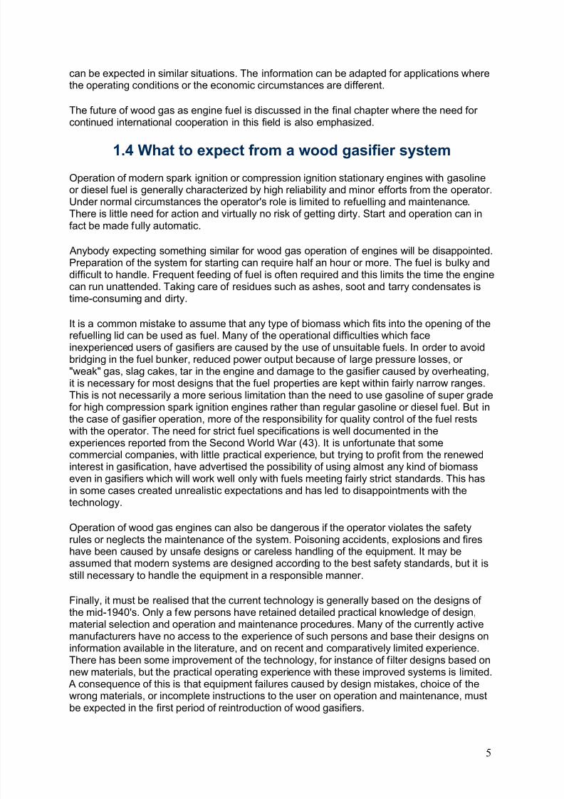
In order to answer this question it is necessary to review a number of aspects of the gasificationtechnology. The type of system considered is schematically illustrated in Figure 2.1.
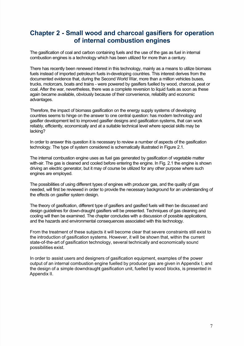
The internal combustion engine uses as fuel gas generated by gasification of vegetable matter with-air. The gas is cleaned and cooled before entering the engine. In Fig. 2.1 the engine is showndriving an electric generator, but it may of course be utilized for any other purpose where suchengines are employed.
The possibilities of using different types of engines with producer gas, and the quality of gasneeded, will first be reviewed in order to provide the necessary background for an understanding of the effects on gasifier system design.
The theory of gasification, different type of gasifiers and gasified fuels will then be discussed anddesign guidelines for down-draught gasifiers will be presented. Techniques of gas cleaning andcooling will then be examined. The chapter concludes with a discussion of possible applications,and the hazards and environmental consequences associated with this technology.
From the treatment of these subjects it will become clear that severe constraints still exist tothe introduction of gasification systems. However, it will be shown that, within the current
state-of-the-art of gasification technology, several technically and economically soundpossibilities exist.
In order to assist users and designers of gasification equipment, examples of the power output of an internal combustion engine fuelled by producer gas are given in Appendix I; andthe design of a simple downdraught gasification unit, fuelled by wood blocks, is presented in Appendix II.
7
8/6/2019 Gasifier Design
http://slidepdf.com/reader/full/gasifier-design 14/139
Figure 2.1 Scheme of a producer gas power plant
2.1 Fuelling of engines by producer gas
Producer gas, the gas generated when wood, charcoal or coal is gasified with air, consists of some 40 per cent combustible gases, mainly carbon monoxide, hydrogen and somemethane. The rest are non-combustible and consists mainly of nitrogen, carbon dioxide andwater vapour.
The gas also contains condensible tar, acids and dust. These impurities may lead tooperational problems and abnormal engine wear. The main problem of gasifier systemdesign is to generate a gas with a high proportion of combustible components and aminimum of impurities. How this can be achieved will be shown later. First, the peculiaritiesof producer gas engines will be discussed both from a theoretical and operational point of view.
2.1.1 Possibilities of using producer gas with different types of engines
Spark ignition engines, normally used with petrol-or kerosene, can be run on producer gasalone. Diesel engines can be converted to full producer gas operation by lowering thecompression ratio and the installation of a spark ignition system. Another possibility is to runa normal unconverted diesel engine in a "dual fuel" mode, whereby the engine drawsanything between 0 and 90 per cent of its power output from producer gas (17), theremaining diesel oil being necessary for ignition of the combustible gas/air mixture. Theadvantage of the latter system lies in its flexibility: in case of malfunctioning of the gasifier or
lack of biomass fuel, an immediate change to full diesel operation is generally possible.
8
8/6/2019 Gasifier Design
http://slidepdf.com/reader/full/gasifier-design 15/139
However, not all types of diesel engines can be converted to the above mode of operation.Compression ratios of ante-chamber and turbulence chamber diesel engines are too high for satisfactory dual fuel operation and use of producer gas in those engines leads to knockingcaused by too high pressures combined with delayed ignition (20). Direct injection dieselengines have lower compression ratios and can generally be successfully converted.
2.1.2 Engine power output using producer gas
The power output from an engine operating on producer gas will be determined by the samefactors as for engines operating on liquid fuels, namely:
- the heating value of the combustible mixture of fuel and air which enters the engine duringeach combustion stroke;
- the amount of combustible mixture which enters the engine during each combustion stroke;
- the efficiency with which the engine converts the thermal of the combustible mixture intomechanical energy (shaft power);
- the number of combustion strokes in a given time (number of revolutions per minute: rpm);
Conversion of an engine to producer gas or dual-fuel operation will generally lead to areduced power output. The reasons for this and possibilities to minimize the power loss willbe discussed below.
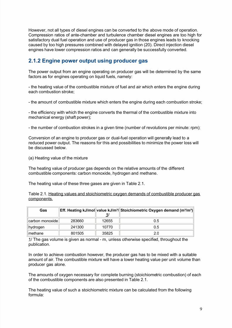
(a) Heating value of the mixture
The heating value of producer gas depends on the relative amounts of the different
combustible components: carbon monoxide, hydrogen and methane.
The heating value of these three gases are given in Table 2.1.
Table 2.1. Heating values and stoichiometric oxygen demands of combustible producer gascomponents.
Gas Eff. Heating kJ/mol value kJ/m³/1/
Stoichiometric Oxygen demand (m³/m³)
carbon monoxide 283660 12655 0.5
hydrogen 241300 10770 0.5
methane 801505 35825 2.0
1/ The gas volume is given as normal - m, unless otherwise specified, throughout thepublication.
In order to achieve combustion however, the producer gas has to be mixed with a suitableamount of air. The combustible mixture will have a lower heating value per unit volume thanproducer gas alone.
The amounts of oxygen necessary for complete burning (stoichiometric combustion) of eachof the combustible components are also presented in Table 2.1.
The heating value of such a stoichiometric mixture can be calculated from the followingformula:
9
8/6/2019 Gasifier Design
http://slidepdf.com/reader/full/gasifier-design 16/139
where:
Hig - is the heating value of a stoichiometric mixture of producer gas and air in kJ/m³VCO - volume fraction of carbon monoxide in the gas (before mixing with air)
- volume fraction of hydrogen in the gas (before mixing with air)
- volume fraction of methane in the gas (before 4 mixing with air).
Heating values of producer gas and air mixtures are around 2500 kJ/m³. When this value iscompared with the heating value of a stoichiometric mixture of petrol and air (about 3800kJ/m³ ), the difference in power output between a given engine fuelled by petrol and byproducer gas becomes apparent. A power loss of about 35% can be expected as a result of the lower heating value of a producer gas/air mixture.
(b) Amount of combustible mixture supplied to the cylinder
The amount of combustible mixture which actually enters the cylinder of an engine isdetermined by the cylinder volume and the pressure of the gas in the cylinder at the momentthe inlet valve closes.
The cylinder volume is a constant for a given engine. The actual pressure of the combustiblemixture at the start of the compression stroke depends however on engine characteristics(especially the design of inlet manifold and air inlet gate), the speed of the engine (higher speeds tend to result in lower pressures), and on the pressure of the gas entering the air inlet
manifold. The former two factors are incorporated in the so called "volumetric efficiency" of the engine, which is defined as the ratio between the actual pressure of the gas in thecylinder and normal pressure (1 atm). Normally engines running at design speeds showvolumetric efficiencies varying between 0.7 and 0.9.
The pressure of the gas at the air inlet manifold depends on the pressure drop over the totalgasification system, i.e. gasifier cooler/cleaner, and gas/air carburettor. This drop reducesagain the entering pressure by a factor of 0.9.
In sum, it must be concluded that the actual amount of combustible gas available in thecylinder will be only 0.65 - 0.8 times the theoretical maximum because of pressure losses onthe way to the cylinder. This will obviously reduce the maximum power output of the engine.
(c) Engine efficiency
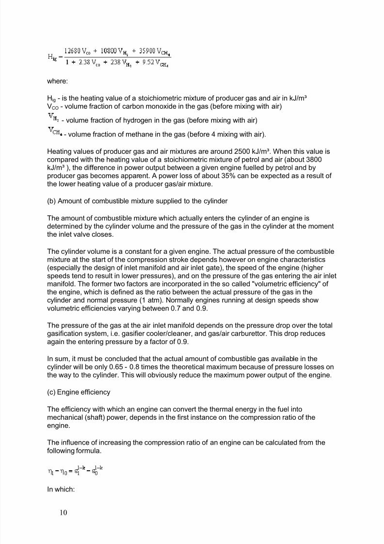
The efficiency with which an engine can convert the thermal energy in the fuel intomechanical (shaft) power, depends in the first instance on the compression ratio of theengine.
The influence of increasing the compression ratio of an engine can be calculated from thefollowing formula.
In which:
10
8/6/2019 Gasifier Design
http://slidepdf.com/reader/full/gasifier-design 17/139
1 = engine thermal efficiency at compression ratio 0 = engine thermal efficiency at compression ratio 1 = engine compression ratio in situation 1 0 = engine compression ratio in situation 0k = a constant equal to 1.3 in the case of producer gas
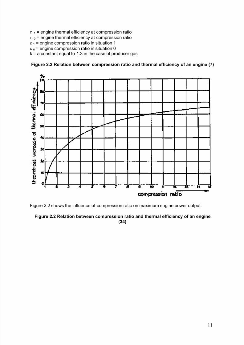
Figure 2.2 Relation between compression ratio and thermal efficiency of an engine (7)
Figure 2.2 shows the influence of compression ratio on maximum engine power output.
Figure 2.2 Relation between compression ratio and thermal efficiency of an engine(34)
11
8/6/2019 Gasifier Design
http://slidepdf.com/reader/full/gasifier-design 18/139
In the case of engines fuelled by petrol, the possible compression ratio is limited by the"octane" number of the fuel, which is a measure of the compression ratio at which detonationor "knocking" (which can lead to severe engine damage) occurs. Producer gas/air mixturesshow higher octane numbers than petrol/air mixtures.
It is for this reason that higher compression ratios (up to 1:11) can be employed withproducer gas, resulting in better engine thermal efficiencies and a relative increase in engineshaft power output.
(d) Engine speed
Because the engine power output is defined per unit time, the engine power output dependson the engine speed.
For diesel engines the power output is nearly linear with the rpm. For spark ignition engines
the power increase is less than linear because of changes in the different efficiency factors.
When the power output of a 4-stroke engine is calculated, allowance must be made for thefact that only one out of every two rotations represents a compression and combustionstroke.
The maximum speed of engines fuelled by producer gas is limited by the combustion velocityof the combustible mixture of producer gas and air. Because this speed is low as comparedto combustible mixtures of petrol and air, the efficiency of the engine can drop dramatically if the combustion speed of the mixture and the average speed of the piston become of thesame order of magnitude.
12
8/6/2019 Gasifier Design
http://slidepdf.com/reader/full/gasifier-design 19/139
In the types of engines that are currently mass-produced, one can expect this phenomenomto occur at engine speeds of around 2500 rpm. Engines fuelled by producer gas shouldtherefore generally be operated below this speed.
2.1.3 Maximizing the power output in producer-gas operation
The possibilities of maximizing the power output are generally related to the theoreticalcauses of power loss discussed in the preceding section. They will be treated in the sameorder here.
(a) Heating value of the mixture
It is evident that the highest heating values for the combustible mixture are achieved at thehighest heating value of the producer gas itself. As will be explained later, the heating valuedepends on the design of the gasifier and on the characteristics of the fuel provided to thegasifier. Minimization of the heat losses from the gasifier is important in order to achieve ahigh heating value of the gas. The moisture content and the size distribution are two of themost important fuel characteristics.
In mixing the producer gas with combustion air there is an additional reason for power lossbecause of changes in the composition of the gas, as well as of variations in pressure dropover the gasifier installation and it is very difficult to maintain continuously a stoichiometricmixture of producer gas and air.
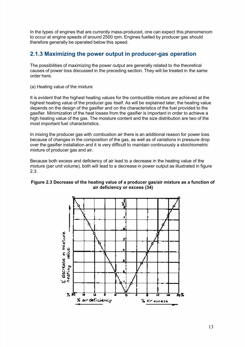
Because both excess and deficiency of air lead to a decrease in the heating value of themixture (per unit volume), both will lead to a decrease in power output as illustrated in figure2.3.
Figure 2.3 Decrease of the heating value of a producer gas/air mixture as a function of air deficiency or excess (34)
13
8/6/2019 Gasifier Design
http://slidepdf.com/reader/full/gasifier-design 20/139
The only feasible way to adjust the mixture to its stoichiometric combustion is by-installing ahand operated valve on the combustion air inlet of the engine and operating this regularly for maximum engine power output.
If maximum engine power output is not needed, it is usually better to operate the engine witha slight excess of air, in order to prevent backfiring in the engine exhaust gas system.
(b) Amount of combustible mixture
Apart from minimizing the pressure drop over the gasifier, cooling and cleaning system andcarburettor (while still maintaining adequate gas/air mixing as discussed above) the amountof combustible mixture per engine combustion stroke can be maximized in two ways:
- increasing the volumetric efficiency of the engine by introducing a wider air inlet manifoldresulting in less gas flow resistance and smaller pressure drops. The influence of a welldesigned air inlet manifold is often underestimated. Experiments by Finkbeiner (11) showthat a well designed air inlet manifold can increase maximum engine power output by 25 per
cent.
- supercharging or turbo charging the engine. From the remarks made earlier, it will be clear that increasing mixture pressure at the engine inlet will increase the engine's maximumpower output. The recent development of turbo-chargers driven by the exhaust gases of theengine makes this option attractive. However care should be taken to water-cool the turbocharger in order to prevent explosions of the combustible mixture.
(c) Engine efficiency
The increase in engine efficiency that can be reached by increasing the compression ratio of
petrol-engines (for example to 1:10 or 1:11) has been discussed earlier. Gas engines havestandard compression ratios in this range and for this reason are especially suited toproducer gas operation.
The influence of correct air/gas mixing has been described by Finkbeiner (11) and hasrecently been studied by Tiedema and van der Weide (42). Installation of suitable gas/air mixing devices (such as the type of carburettor developed by TNO, (the Dutch parastatalresearch organisation) can lead to an increase in maximum engine power output of 10-15percent as compared to the usual two-valve pipe and chamber type carburettors.
(d) Engine speed and ignition advance
Because of the slow combustion speed of the gas/air mixture the timing of the ignition inproducer gas fuelled petrol engines must generally be changed.
The optimal timing of the ignition in petrol engines depends on the load and the enginespeed. This is also the case in producer gas operation. Experiments by Middleton and Bruce(29) indicate that, in general, ignition timing should be advanced by 10° - 15°, leading toignition advances of 35° - 40° before top-dead-centre (TDC).
If a diesel engine is operated in a dual fuel mode, it is also advantageous to advance thetiming of the diesel fuel injection. Again the necessary advance depends on the enginespeed, as shown by Nordstrom (33), Tiedema e al. (42) report good results with injection
timing advances of 10° as compared to full diesel operation.
14
8/6/2019 Gasifier Design
http://slidepdf.com/reader/full/gasifier-design 21/139
A problem sometimes encountered in dual fuelled engines is detonation. Apart from engineswith too high compression ratios (above 1:16), this phenomenon mostly occurs when anattempt is made to remedy low power output of the engine by introducing increased amountsof diesel fuel. Depending on the composition of the producer gas and on the mixture strengthof the fuel, an excess of pilot fuel can lead to detonation. For this reason the amount of pilotdiesel fuel, in dual fuel operation, must have an upper limit. Generally a limitation at around30 percent of maximum engine power output will prevent detonation.
The amount of pilot diesel fuel in dual fuel operation also has a lower limit. Depending on theengine speed (30) a certain minimum amount of diesel fuel per cycle has to be injected inorder to ensure ignition. The minimum amounts vary from 3-5 mm per cycle.
In practical operation however a somewhat higher amount of diesel fuel is injected per cyclein order to stay on the safe side. Diesel fuel injections of 8-9 mm³ per cycle and cylinder isrecommended.
2.1.4 Resulting power output
Assuming that the engine modifications described above are correctly implemented,decrease in maximum power output of petrol engines without turbo or supercharging can belimited to about 30 percent. Turbo or supercharged combustion running engines on producer gas can have power outputs equal to those in petrol operation.
Derating of direct injection diesel engines in dual fuel operation can usually be limited to 15 -20 percent (80 percent producer gas, 20 percent diesel fuel).
2.1.5 Gas quality requirements for trouble-free operation
When a gasifier system is used in conjunction with an internal combustion engine, animportant requirement is that the engine is supplied with a gas that is sufficiently free fromdust, tars and acids. The tolerable amounts of these substances will vary depending on thetype and outfit of the engine. Tiedema and van der Weide (38) give as tolerable averageamounts for currently available engines the following values:
dust: lower than 50 mg/m³ gas preferably 5 mg/m³ gas
tars: lower than 500 mg/m³ gas
acids: lower than 50 mg/m³ gas (measured as acetic acid).
2.1.6 Use of Stirling engines or gas turbines with producer gas
In addition to the use of producer gas with internal combustion engines, other possibilitiesare the combination of gasifiers with gas turbines or with Stirling engines. Because high inletgas temperatures aid the thermal efficiency of gas turbines, these in principle present anattractive option for converting hot producer gas into mechanical and/or electric power.However, the current state-of-art of gasifier as well as turbine technology prevents their use.Gas turbines are very sensitive to dust, especially at high inlet temperatures, and it isdoubtful if gas quality requirements can be met with the filtering systems described in section2.6.
Another problem stems from the sensitivity of current turbine vanes to corrosion by alkaline
vapours (Na, K and Ca) which are usually present in tiny amounts in producer gas. An
15
8/6/2019 Gasifier Design
http://slidepdf.com/reader/full/gasifier-design 22/139
optimum system would require a pressurised gasifier, which would add considerably to costand complexity and probably will only be economic for very large installations.
Beagle (6) mentions the possibility of using Stirling engines in conjunction with gasifiersespecially in micro scale applications. Stirling engines in this power range are now becomingcommercially available.
Because of a number of advantages as compared to the use of internal combustion engines(low maintenance, high efficiency, low lubricant consumption etc.) this concept should befurther evaluated and tested.
2.2 Theory of gasification
The substance of a solid fuel is usually composed of the elements carbon, hydrogen andoxygen. In addition there may be nitrogen and sulphur, but since these are present only insmall quantities they will be disregarded in the following discussion.
In the types of gasifiers considered here, the solid fuel is heated by combustion of a part of the fuel. The combustion gases are then reduced by being passed through a bed of fuel athigh temperature.
In complete combustion, carbon dioxide is obtained from the carbon and water from thehydrogen. Oxygen from the fuel will of course be incorporated in the combustion products,thereby decreasing the amount of combustion air needed.
Oxidation, or combustion, is described by the following chemical reaction formulae:
- 401.9 kJ/mol- 241.1 kJ/mol
These formulae mean that burning 1 gram atom, i.e. 12.00 g of carbon, to dioxide, a heatquantity of 401.9 kJ is released, and that a heat quantity of 241.1 kJ results from theoxidation of 1 gram molecule, i.e. 2.016 g of hydrogen to water vapour.
In all types of gasifiers, the carbon dioxide (CO2) and water vapour (H2O) are converted(reduced) as much as possible to carbon monoxide, hydrogen and methane, which are themain combustible components of producer gas.
The most important reactions that take place in the reduction zone of a gasifier between thedifferent gaseous and solid reactants are given below. A minus sign indicates that heat isgenerated in the reaction, a positive sign that the reaction requires heat.
a) + 164.9 kJ/kmol
b) + 122.6 kJ/kmol
c) + 42.3 kJ/kmol
d) 0
e) - 205.9 kJ/kmol
16
8/6/2019 Gasifier Design
http://slidepdf.com/reader/full/gasifier-design 23/139
Equations (a) and (b), which are the main reactions of reduction, show that reductionrequires heat. Therefore the gas temperature will decrease during reduction.
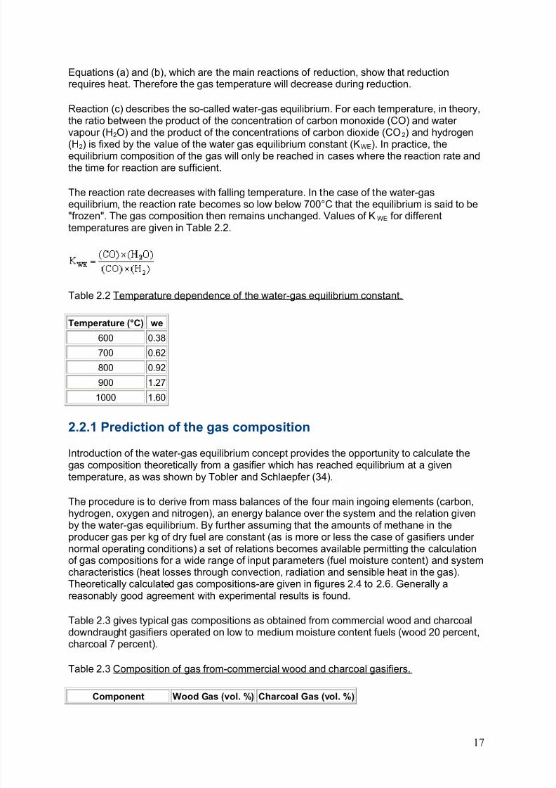
Reaction (c) describes the so-called water-gas equilibrium. For each temperature, in theory,the ratio between the product of the concentration of carbon monoxide (CO) and water vapour (H
2O) and the product of the concentrations of carbon dioxide (CO
2) and hydrogen
(H2) is fixed by the value of the water gas equilibrium constant (KWE). In practice, theequilibrium composition of the gas will only be reached in cases where the reaction rate andthe time for reaction are sufficient.
The reaction rate decreases with falling temperature. In the case of the water-gasequilibrium, the reaction rate becomes so low below 700°C that the equilibrium is said to be"frozen". The gas composition then remains unchanged. Values of KWE for differenttemperatures are given in Table 2.2.
Table 2.2 Temperature dependence of the water-gas equilibrium constant.
Temperature (°C) we
600 0.38
700 0.62
800 0.92
900 1.27
1000 1.60
2.2.1 Prediction of the gas composition
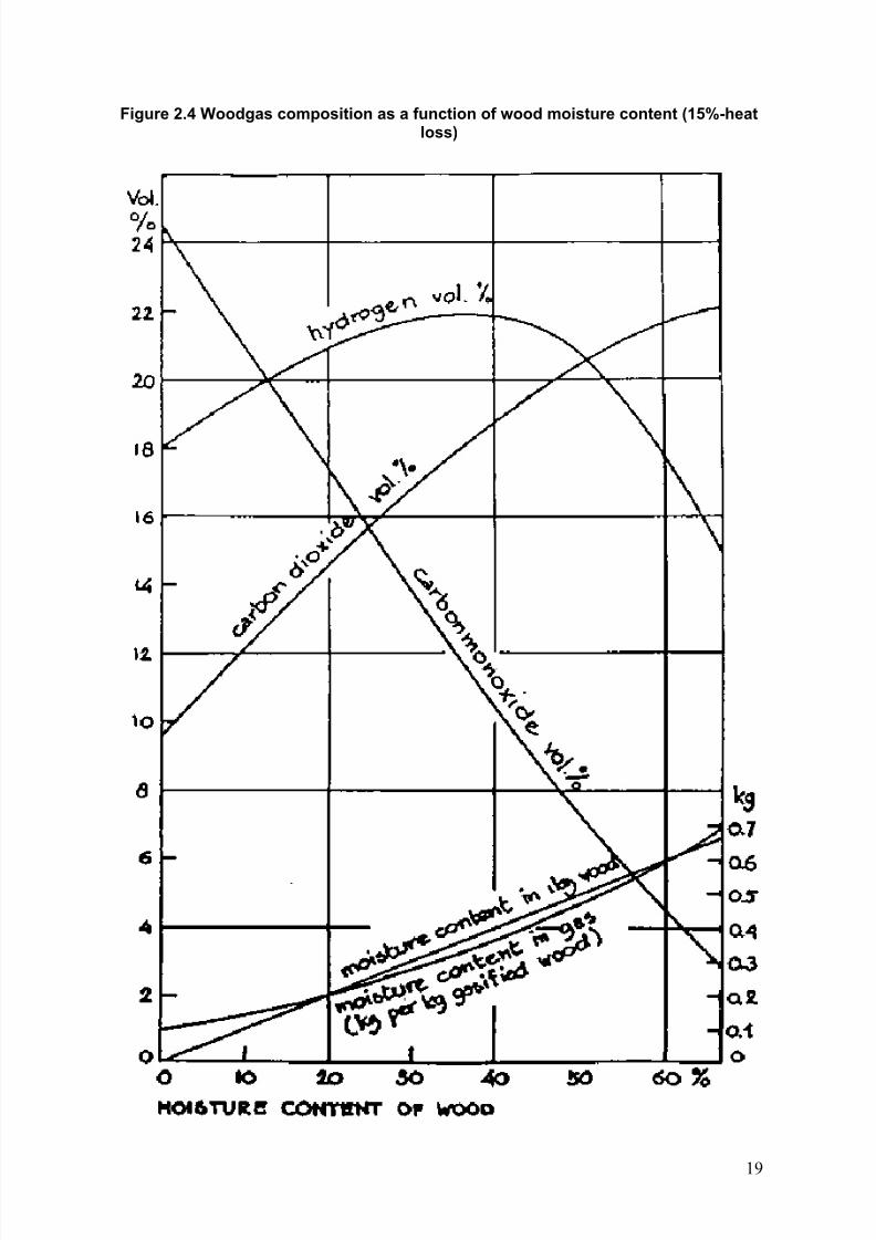
Introduction of the water-gas equilibrium concept provides the opportunity to calculate thegas composition theoretically from a gasifier which has reached equilibrium at a giventemperature, as was shown by Tobler and Schlaepfer (34).
The procedure is to derive from mass balances of the four main ingoing elements (carbon,hydrogen, oxygen and nitrogen), an energy balance over the system and the relation givenby the water-gas equilibrium. By further assuming that the amounts of methane in theproducer gas per kg of dry fuel are constant (as is more or less the case of gasifiers under
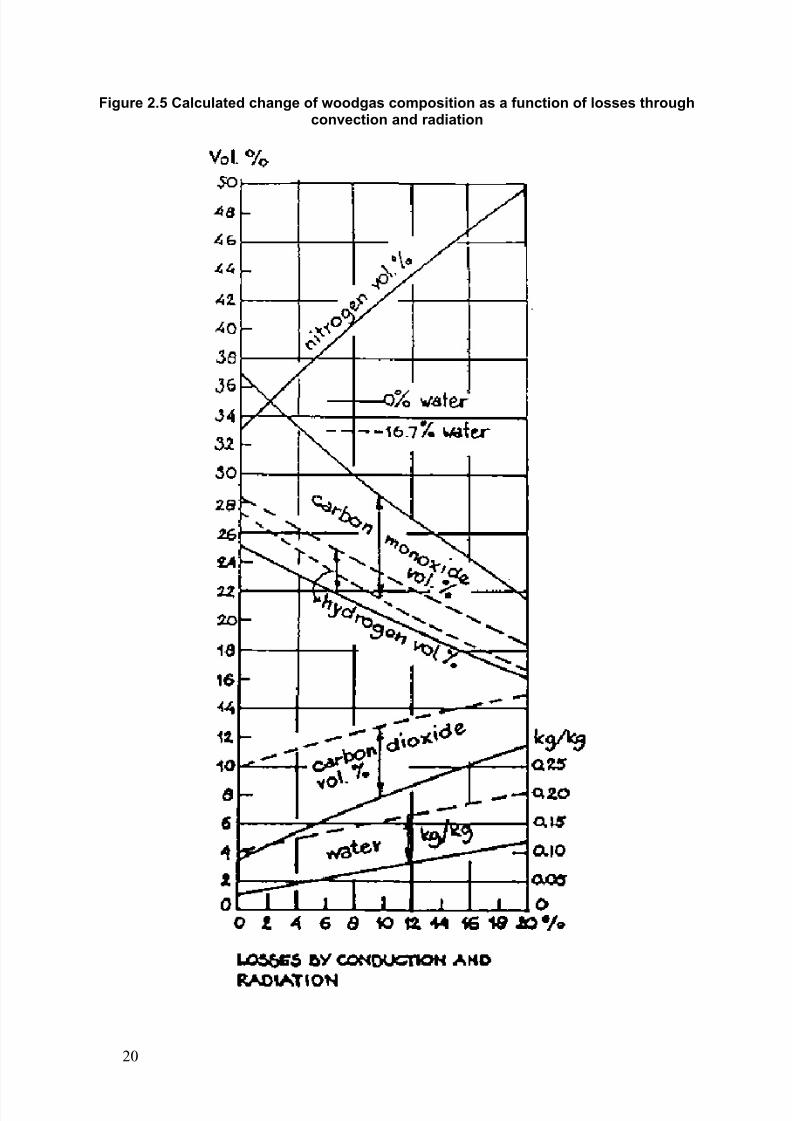
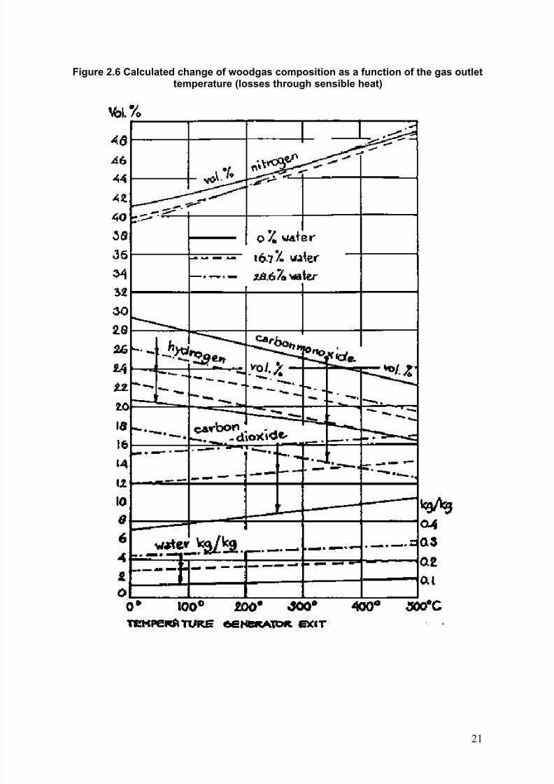
normal operating conditions) a set of relations becomes available permitting the calculationof gas compositions for a wide range of input parameters (fuel moisture content) and systemcharacteristics (heat losses through convection, radiation and sensible heat in the gas).Theoretically calculated gas compositions-are given in figures 2.4 to 2.6. Generally areasonably good agreement with experimental results is found.
Table 2.3 gives typical gas compositions as obtained from commercial wood and charcoaldowndraught gasifiers operated on low to medium moisture content fuels (wood 20 percent,charcoal 7 percent).
Table 2.3 Composition of gas from-commercial wood and charcoal gasifiers.
Component Wood Gas (vol. %) Charcoal Gas (vol. %)
17
8/6/2019 Gasifier Design
http://slidepdf.com/reader/full/gasifier-design 24/139
8/6/2019 Gasifier Design
http://slidepdf.com/reader/full/gasifier-design 25/139
Figure 2.4 Woodgas composition as a function of wood moisture content (15%-heatloss)
19
8/6/2019 Gasifier Design
http://slidepdf.com/reader/full/gasifier-design 26/139
Figure 2.5 Calculated change of woodgas composition as a function of losses throughconvection and radiation
20
8/6/2019 Gasifier Design
http://slidepdf.com/reader/full/gasifier-design 27/139
Figure 2.6 Calculated change of woodgas composition as a function of the gas outlettemperature (losses through sensible heat)
21
8/6/2019 Gasifier Design
http://slidepdf.com/reader/full/gasifier-design 28/139
2.3 Types of gasifiers
2.3.1 Updraught or counter current gasifier
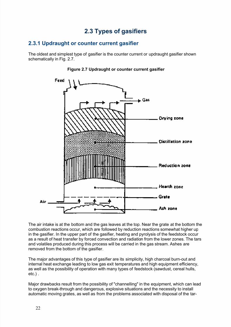
The oldest and simplest type of gasifier is the counter current or updraught gasifier shownschematically in Fig. 2.7.
Figure 2.7 Updraught or counter current gasifier
The air intake is at the bottom and the gas leaves at the top. Near the grate at the bottom the
combustion reactions occur, which are followed by reduction reactions somewhat higher upin the gasifier. In the upper part of the gasifier, heating and pyrolysis of the feedstock occur as a result of heat transfer by forced convection and radiation from the lower zones. The tarsand volatiles produced during this process will be carried in the gas stream. Ashes areremoved from the bottom of the gasifier.
The major advantages of this type of gasifier are its simplicity, high charcoal burn-out andinternal heat exchange leading to low gas exit temperatures and high equipment efficiency,as well as the possibility of operation with many types of feedstock (sawdust, cereal hulls,etc.) .
Major drawbacks result from the possibility of "channelling" in the equipment, which can leadto oxygen break-through and dangerous, explosive situations and the necessity to installautomatic moving grates, as well as from the problems associated with disposal of the tar-
22
8/6/2019 Gasifier Design
http://slidepdf.com/reader/full/gasifier-design 29/139
containing condensates that result from the gas cleaning operations. The latter is of minor importance if the gas is used for direct heat applications, in which case the tars are simplyburnt.
2.3.2 Downdraught or co-current gasifiers
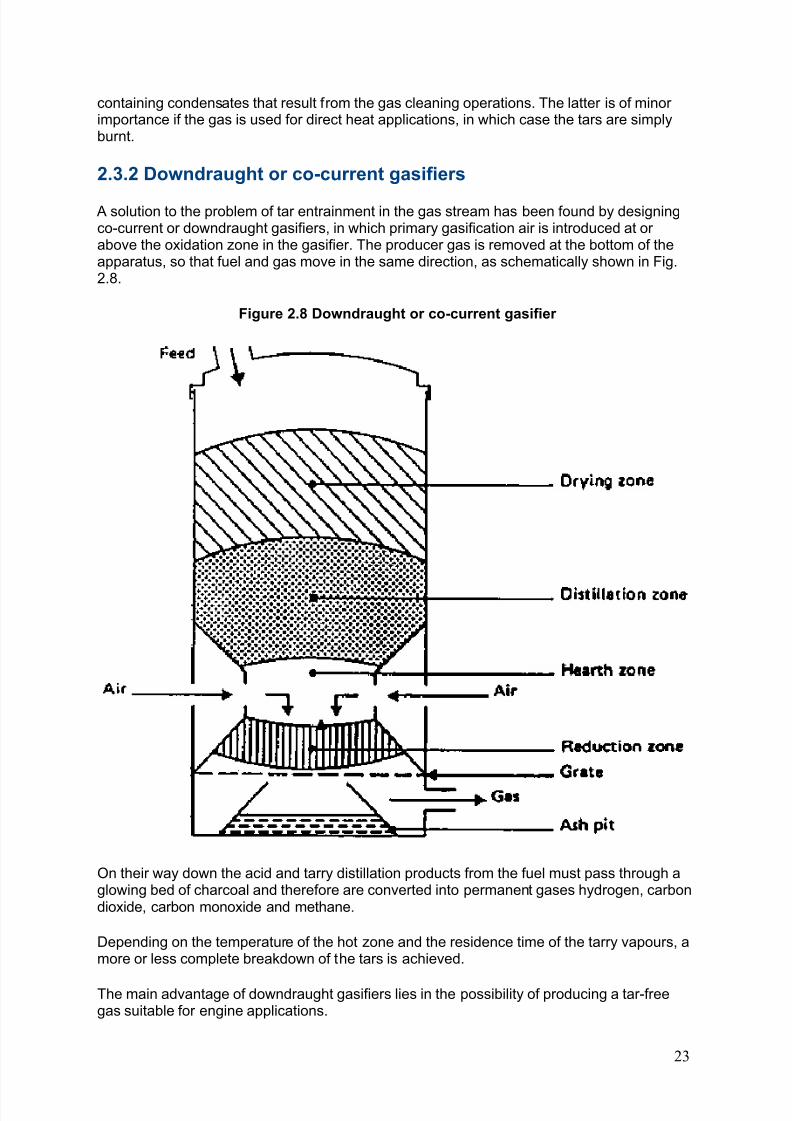
A solution to the problem of tar entrainment in the gas stream has been found by designingco-current or downdraught gasifiers, in which primary gasification air is introduced at or above the oxidation zone in the gasifier. The producer gas is removed at the bottom of theapparatus, so that fuel and gas move in the same direction, as schematically shown in Fig.2.8.
Figure 2.8 Downdraught or co-current gasifier
On their way down the acid and tarry distillation products from the fuel must pass through aglowing bed of charcoal and therefore are converted into permanent gases hydrogen, carbondioxide, carbon monoxide and methane.
Depending on the temperature of the hot zone and the residence time of the tarry vapours, amore or less complete breakdown of the tars is achieved.
The main advantage of downdraught gasifiers lies in the possibility of producing a tar-freegas suitable for engine applications.
23
8/6/2019 Gasifier Design
http://slidepdf.com/reader/full/gasifier-design 30/139
In practice, however, a tar-free gas is seldom if ever achieved over the whole operatingrange of the equipment: tar-free operating turn-down ratios of a factor 3 are consideredstandard; a factor 5-6 is considered excellent.
Because of the lower level of organic components in the condensate, downdraught gasifierssuffer less from environmental objections than updraught gasifiers.
A major drawback of downdraught equipment lies in its inability to operate on a number of unprocessed fuels. In particular, fluffy, low density materials give rise to flow problems andexcessive pressure drop, and the solid fuel must be pelletized or briquetted before use.Downdraught gasifiers also suffer from the problems associated with high ash content fuels(slagging) to a larger extent than updraught gasifiers.
Minor drawbacks of the downdraught system, as compared to updraught, are somewhatlower efficiency resulting from the lack of internal heat exchange as well as the lower heatingvalue of the gas. Besides this, the necessity to maintain uniform high temperatures over agiven cross-sectional area makes impractical the use of downdraught gasifiers in a power
range above about 350 kW (shaft power).
2.3.3. Cross-draught gasifier
Cross-draught gasifiers, schematically illustrated in Figure 2.9 are an adaptation for the useof charcoal. Charcoal gasification results in very high temperatures (1500 °C and higher) inthe oxidation zone which can lead to material problems. In cross draught gasifiers insulationagainst these high temperatures is provided by the fuel (charcoal) itself.
Advantages of the system lie in the very small scale at which it can be operated. Installationsbelow 10 kW (shaft power) can under certain conditions be economically feasible. The
reason is the very simple gas-cleaning train (only a cyclone and a hot filter) which can beemployed when using this type of gasifier in conjunction with small engines.
A disadvantage of cross-draught gasifiers is their minimal tar-converting capabilities and theconsequent need for high quality (low volatile content) charcoal.
It is because of the uncertainty of charcoal quality that a number of charcoal gasifiers employthe downdraught principle, in order to maintain at least a minimal tar-cracking capability.
Figure 2.9 Cross-draught gasifier
2.3.4. Fluidized bed gasifier The operation of both up and downdraught gasifiers is influenced by the morphological,physical and chemical properties of the fuel. Problems commonly encountered are: lack of bunkerflow, slagging and extreme pressure drop over the gasifier
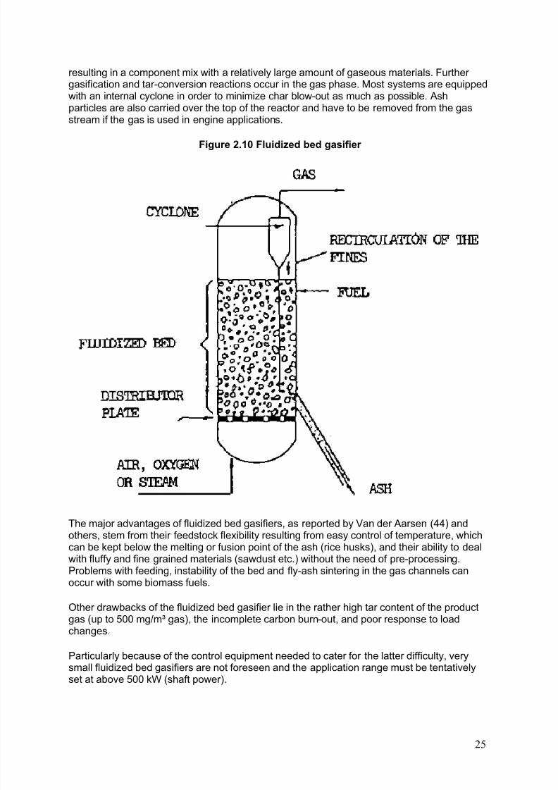
A design approach aiming at the removal of the above difficulties is the fluidized bed gasifier illustrated schematically in Fig. 2.10.
Air is blown through a bed of solid particles at a sufficient velocity to keep these in a state of suspension. The bed is originally externally heated and the feedstock is introduced as soonas a sufficiently high temperature is reached. The fuel particles are introduced at the bottomof the reactor, very quickly mixed with the bed material and almost instantaneously heatedup to the bed temperature. As a result of this treatment the fuel is pyrolysed very fast,
24
8/6/2019 Gasifier Design
http://slidepdf.com/reader/full/gasifier-design 31/139
resulting in a component mix with a relatively large amount of gaseous materials. Further gasification and tar-conversion reactions occur in the gas phase. Most systems are equippedwith an internal cyclone in order to minimize char blow-out as much as possible. Ashparticles are also carried over the top of the reactor and have to be removed from the gasstream if the gas is used in engine applications.
Figure 2.10 Fluidized bed gasifier
The major advantages of fluidized bed gasifiers, as reported by Van der Aarsen (44) andothers, stem from their feedstock flexibility resulting from easy control of temperature, whichcan be kept below the melting or fusion point of the ash (rice husks), and their ability to dealwith fluffy and fine grained materials (sawdust etc.) without the need of pre-processing.Problems with feeding, instability of the bed and fly-ash sintering in the gas channels canoccur with some biomass fuels.
Other drawbacks of the fluidized bed gasifier lie in the rather high tar content of the productgas (up to 500 mg/m³ gas), the incomplete carbon burn-out, and poor response to loadchanges.
Particularly because of the control equipment needed to cater for the latter difficulty, verysmall fluidized bed gasifiers are not foreseen and the application range must be tentativelyset at above 500 kW (shaft power).
25

8/6/2019 Gasifier Design
http://slidepdf.com/reader/full/gasifier-design 32/139
Fluidized bed gasifiers are currently available on a semi-commercial basis from severalmanufacturers in Europe and U.S.A.
2.3.5 Other types of gasifiers
A number of other biomass gasifier systems (double fired, entrained bed, molten bath), whichare partly spin-offs from coal gasification technology, are currently under development. Insome cases these systems incorporate unnecessary refinements and complications, inothers both the size and sophistication of the equipment make near term application indeveloping countries unlikely. For these reasons they are omitted from this account.
2.4 Gasification fuels
2.4.1 Need for selection of the right gasifier for each fuelBiomass fuels available for gasification include charcoal, wood and wood waste (branches,twigs, roots, bark, woodshavings and sawdust) as well as a multitude of agricultural residues(maize cobs, coconut shells, coconut husks, cereal straws, rice husks, etc.) and peat.
Because those fuels differ greatly in their chemical, physical and morphological properties,they make different demands on the method of gasification and consequently requiredifferent reactor designs or even gasification technologies. It is for this reason that, during acentury of gasification experience, a large number of different gasifiers has been developedand marketed, all types geared towards handling the specific properties of a typical fuel or range of fuels.
Thus it follows that the "universal" gasifier, able to handle all or most fuels or fuel types, doesnot exist, and in all probability will not exist in the foreseeable future.
The range of designs includes updraught, downdraught, crossdraught, fluidized bed as wellas other biomass gasification systems of less importance (see section 2.3). All systems showrelative advantages and disadvantages with respect to fuel type, application and simplicity of operation, and for this reason each will have its own technical and/or economic advantagesin a particular set of circumstances.
Each type of gasifier will operate satisfactorily with respect to stability, gas quality, efficiency
and pressure losses only within certain ranges of the fuel properties of which the mostimportant are:
- energy content- moisture content- volatile matter - ash content and ash chemical composition- reactivity- size and size distribution- bulk density- charring properties
26
8/6/2019 Gasifier Design
http://slidepdf.com/reader/full/gasifier-design 33/139
Before choosing a gasifier for any individual fuel it is important to ensure that the fuel meetsthe requirements of the gasifier or that it can be treated to meet these requirements. Practicaltests are needed if the fuel has not previously been successfully gasified.
In the next sections the most important fuel properties will be discussed and fuels of currentinterest will be reviewed.
2.4.2 Energy content of the fuel
The choice of a fuel for gasification will in part be decided by its heating value. The method of measurement of the fuel energy content will influence the estimate of efficiency of a givengasification system. Reporting of fuel heating values is often confusing since at least threedifferent bases are used:
- fuel higher heating values as obtained in an adiabatic bomb calorimeter. These valuesinclude the heat of condensation of the water that is produced during combustion. Because itis very difficult to recover the heat of condensation in actual gasification operations thesevalues present a too optimistic view of the fuel energy content;
- fuel higher heating values on a moisture-free basis, which disregard the actual moisturecontent of the fuel and so provide even more optimistic estimates of energy content;
- fuel higher heating values on a moisture and ash free basis, which disregard theincombustible components and consequently provide estimates of energy content too highfor a given weight of fuel, especially in the case of some agricultural residues (rice husks).
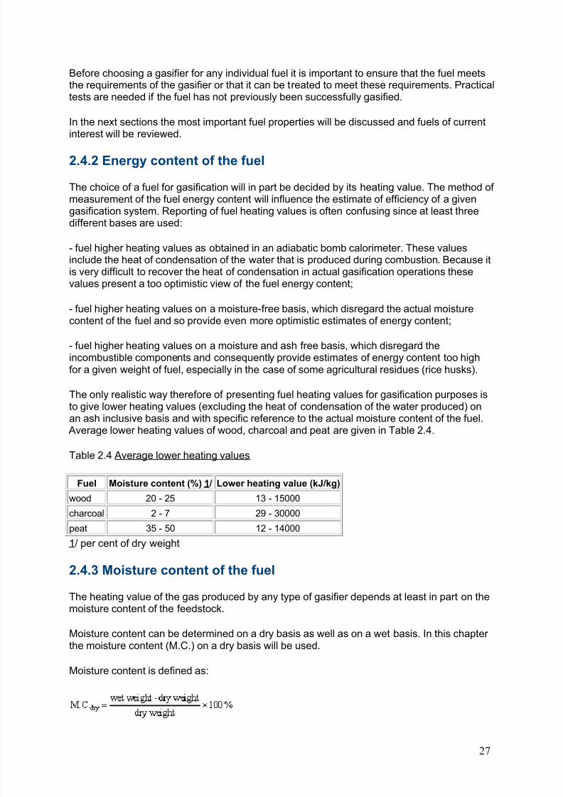
The only realistic way therefore of presenting fuel heating values for gasification purposes isto give lower heating values (excluding the heat of condensation of the water produced) on
an ash inclusive basis and with specific reference to the actual moisture content of the fuel. Average lower heating values of wood, charcoal and peat are given in Table 2.4.
Table 2.4 Average lower heating values
Fuel Moisture content (%) 1/ Lower heating value (kJ/kg)
wood 20 - 25 13 - 15000
charcoal 2 - 7 29 - 30000
peat 35 - 50 12 - 14000
1/ per cent of dry weight
2.4.3 Moisture content of the fuel
The heating value of the gas produced by any type of gasifier depends at least in part on themoisture content of the feedstock.
Moisture content can be determined on a dry basis as well as on a wet basis. In this chapter the moisture content (M.C.) on a dry basis will be used.
Moisture content is defined as:
27
8/6/2019 Gasifier Design
http://slidepdf.com/reader/full/gasifier-design 34/139
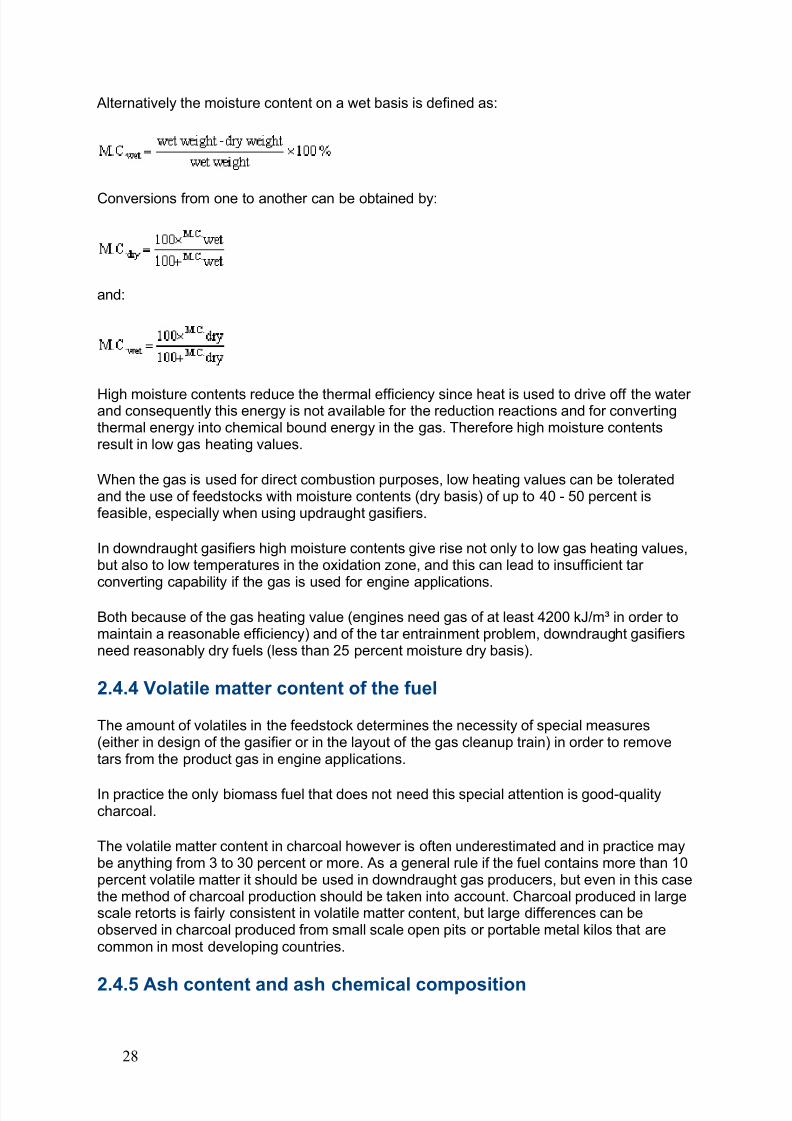
Alternatively the moisture content on a wet basis is defined as:
Conversions from one to another can be obtained by:
and:
High moisture contents reduce the thermal efficiency since heat is used to drive off the water and consequently this energy is not available for the reduction reactions and for convertingthermal energy into chemical bound energy in the gas. Therefore high moisture contentsresult in low gas heating values.
When the gas is used for direct combustion purposes, low heating values can be toleratedand the use of feedstocks with moisture contents (dry basis) of up to 40 - 50 percent isfeasible, especially when using updraught gasifiers.
In downdraught gasifiers high moisture contents give rise not only to low gas heating values,but also to low temperatures in the oxidation zone, and this can lead to insufficient tar
converting capability if the gas is used for engine applications.Both because of the gas heating value (engines need gas of at least 4200 kJ/m³ in order tomaintain a reasonable efficiency) and of the tar entrainment problem, downdraught gasifiersneed reasonably dry fuels (less than 25 percent moisture dry basis).
2.4.4 Volatile matter content of the fuel
The amount of volatiles in the feedstock determines the necessity of special measures(either in design of the gasifier or in the layout of the gas cleanup train) in order to removetars from the product gas in engine applications.
In practice the only biomass fuel that does not need this special attention is good-qualitycharcoal.
The volatile matter content in charcoal however is often underestimated and in practice maybe anything from 3 to 30 percent or more. As a general rule if the fuel contains more than 10percent volatile matter it should be used in downdraught gas producers, but even in this casethe method of charcoal production should be taken into account. Charcoal produced in largescale retorts is fairly consistent in volatile matter content, but large differences can beobserved in charcoal produced from small scale open pits or portable metal kilos that arecommon in most developing countries.
2.4.5 Ash content and ash chemical composition
28
8/6/2019 Gasifier Design
http://slidepdf.com/reader/full/gasifier-design 35/139
Ashes can cause a variety of problems particularly in up or downdraught gasifiers. Slaggingor clinker formation in the reactor, caused by melting and agglomeration of ashes, at the bestwill greatly add to the amount of labour required to operate the gasifier If no specialmeasures are taken, slagging can lead to excessive tar formation and/or complete blockingof the reactor. A worst case is the possibility of air-channelling which can lead to a risk of explosion, especially in updraught gasifiers.
Whether or not slagging occurs depends on the ash content of the fuel, the meltingcharacteristics of the ash, and the temperature pattern in the gasifier. Local hightemperatures in voids in the fuel bed in the oxidation zone, caused by bridging in the bed,may cause slagging even using fuels with a high ash melting temperature.
In general, no slagging is observed with fuels having ash contents below 5-6 percent. Severeslagging can be expected for fuels having ash contents of 12 percent and above. For fuelswith ash contents between 6 and 12 percent, the slagging behaviour depends to a largeextent on the ash melting temperature, which is influenced by the presence of trace elementsgiving rise to the formation of low melting point eutectic mixtures.
For gasification purposes the melting behaviour of the fuel ash should be determined in bothoxidating and reducing atmospheres.
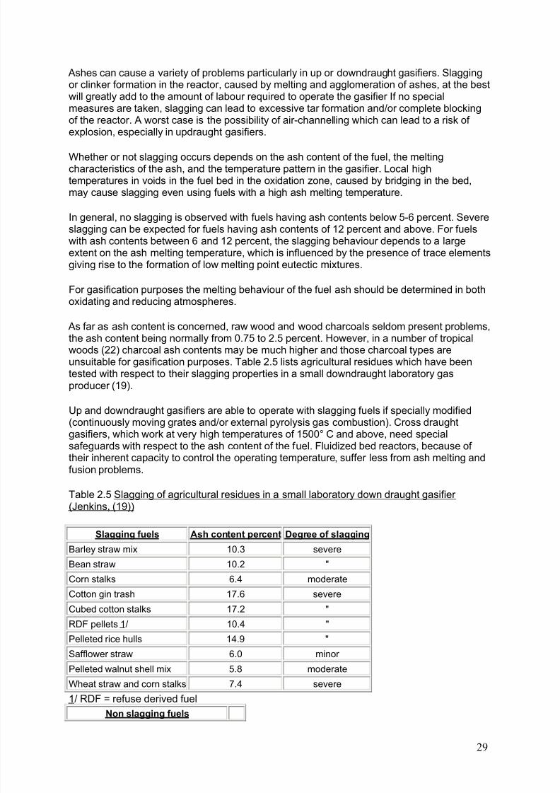
As far as ash content is concerned, raw wood and wood charcoals seldom present problems,the ash content being normally from 0.75 to 2.5 percent. However, in a number of tropicalwoods (22) charcoal ash contents may be much higher and those charcoal types areunsuitable for gasification purposes. Table 2.5 lists agricultural residues which have beentested with respect to their slagging properties in a small downdraught laboratory gasproducer (19).
Up and downdraught gasifiers are able to operate with slagging fuels if specially modified(continuously moving grates and/or external pyrolysis gas combustion). Cross draughtgasifiers, which work at very high temperatures of 1500° C and above, need specialsafeguards with respect to the ash content of the fuel. Fluidized bed reactors, because of their inherent capacity to control the operating temperature, suffer less from ash melting andfusion problems.
Table 2.5 Slagging of agricultural residues in a small laboratory down draught gasifier (Jenkins, (19))
Slagging fuels Ash content percent Degree of slagging
Barley straw mix 10.3 severe
Bean straw 10.2 "
Corn stalks 6.4 moderate
Cotton gin trash 17.6 severe
Cubed cotton stalks 17.2 "
RDF pellets 1/ 10.4 "
Pelleted rice hulls 14.9 "
Safflower straw 6.0 minor
Pelleted walnut shell mix 5.8 moderate
Wheat straw and corn stalks 7.4 severe
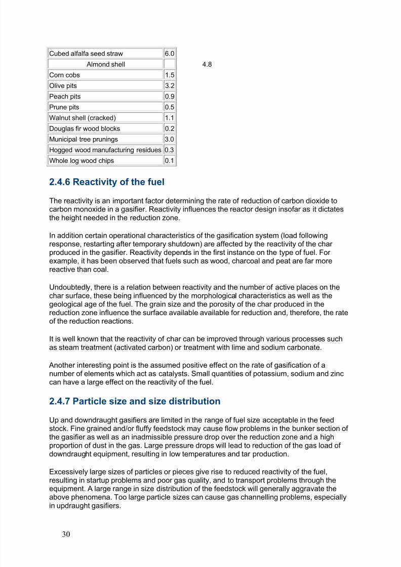
1/ RDF = refuse derived fuelNon slagging fuels
29
8/6/2019 Gasifier Design
http://slidepdf.com/reader/full/gasifier-design 36/139
Cubed alfalfa seed straw 6.0
Almond shell 4.8
Corn cobs 1.5
Olive pits 3.2
Peach pits 0.9Prune pits 0.5
Walnut shell (cracked) 1.1
Douglas fir wood blocks 0.2
Municipal tree prunings 3.0
Hogged wood manufacturing residues 0.3
Whole log wood chips 0.1
2.4.6 Reactivity of the fuel
The reactivity is an important factor determining the rate of reduction of carbon dioxide tocarbon monoxide in a gasifier. Reactivity influences the reactor design insofar as it dictatesthe height needed in the reduction zone.
In addition certain operational characteristics of the gasification system (load followingresponse, restarting after temporary shutdown) are affected by the reactivity of the char produced in the gasifier. Reactivity depends in the first instance on the type of fuel. For example, it has been observed that fuels such as wood, charcoal and peat are far morereactive than coal.
Undoubtedly, there is a relation between reactivity and the number of active places on the
char surface, these being influenced by the morphological characteristics as well as thegeological age of the fuel. The grain size and the porosity of the char produced in thereduction zone influence the surface available available for reduction and, therefore, the rateof the reduction reactions.
It is well known that the reactivity of char can be improved through various processes suchas steam treatment (activated carbon) or treatment with lime and sodium carbonate.
Another interesting point is the assumed positive effect on the rate of gasification of anumber of elements which act as catalysts. Small quantities of potassium, sodium and zinccan have a large effect on the reactivity of the fuel.
2.4.7 Particle size and size distribution
Up and downdraught gasifiers are limited in the range of fuel size acceptable in the feedstock. Fine grained and/or fluffy feedstock may cause flow problems in the bunker section of the gasifier as well as an inadmissible pressure drop over the reduction zone and a highproportion of dust in the gas. Large pressure drops will lead to reduction of the gas load of downdraught equipment, resulting in low temperatures and tar production.
Excessively large sizes of particles or pieces give rise to reduced reactivity of the fuel,resulting in startup problems and poor gas quality, and to transport problems through theequipment. A large range in size distribution of the feedstock will generally aggravate the
above phenomena. Too large particle sizes can cause gas channelling problems, especiallyin updraught gasifiers.
30
8/6/2019 Gasifier Design
http://slidepdf.com/reader/full/gasifier-design 37/139
Acceptable fuel sizes fox gasification systems depend to a certain extent on the design of theunits. In general, wood gasifiers operate on wood blocks and woodchips ranging from 8 x 4 x4 cm. to 1 x 0.5 x 0.5 cm. Charcoal gasifiers are generally fuelled by charcoal lumps rangingbetween 1 x 1 x 1 cm. and 3 x 3 x 3 cm. Fluidized bed gasifiers are normally able to handlefuels with particle diameters varying between 0.1 and 20 mm.
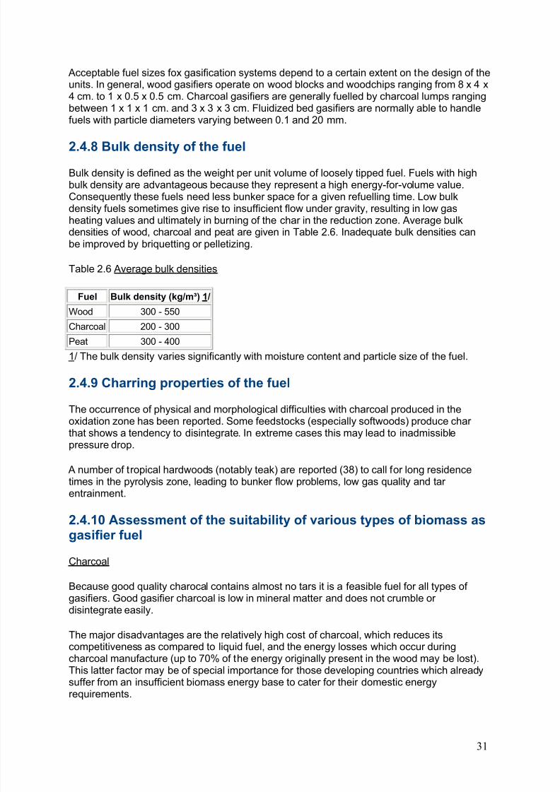
2.4.8 Bulk density of the fuel
Bulk density is defined as the weight per unit volume of loosely tipped fuel. Fuels with highbulk density are advantageous because they represent a high energy-for-volume value.Consequently these fuels need less bunker space for a given refuelling time. Low bulkdensity fuels sometimes give rise to insufficient flow under gravity, resulting in low gasheating values and ultimately in burning of the char in the reduction zone. Average bulkdensities of wood, charcoal and peat are given in Table 2.6. Inadequate bulk densities canbe improved by briquetting or pelletizing.
Table 2.6 Average bulk densities
Fuel Bulk density (kg/m³) 1/
Wood 300 - 550
Charcoal 200 - 300
Peat 300 - 400
1/ The bulk density varies significantly with moisture content and particle size of the fuel.
2.4.9 Charring properties of the fuel
The occurrence of physical and morphological difficulties with charcoal produced in theoxidation zone has been reported. Some feedstocks (especially softwoods) produce char that shows a tendency to disintegrate. In extreme cases this may lead to inadmissiblepressure drop.
A number of tropical hardwoods (notably teak) are reported (38) to call for long residencetimes in the pyrolysis zone, leading to bunker flow problems, low gas quality and tar entrainment.
2.4.10 Assessment of the suitability of various types of biomass asgasifier fuel
Charcoal
Because good quality charocal contains almost no tars it is a feasible fuel for all types of gasifiers. Good gasifier charcoal is low in mineral matter and does not crumble or disintegrate easily.
The major disadvantages are the relatively high cost of charcoal, which reduces itscompetitiveness as compared to liquid fuel, and the energy losses which occur duringcharcoal manufacture (up to 70% of the energy originally present in the wood may be lost).This latter factor may be of special importance for those developing countries which alreadysuffer from an insufficient biomass energy base to cater for their domestic energy
requirements.
31
8/6/2019 Gasifier Design
http://slidepdf.com/reader/full/gasifier-design 38/139
Experience has shown that most types of wood as well as some agricultural residues (e.g.coconut shell) can provide first class gasification charcoal.
Wood
Most wood species have ash contents below two percent and are therefore suitable fuels foxfixed bed gasifiers
Because of the high volatile content of wood, updraught systems produce a tar-containinggas suitable mainly for direct burning. Cleaning of the gas to make it suitable for engines israther difficult and capital and labour intensive. Downdraught systems can be designed todeliver a virtually tar-free product gas in a certain capacity range when fuelled by woodblocks or wood chips of low moisture content. After passing through a relatively simple clean-up train the gas can be used in internal combustion engines.
Sawdust
Most currently available downdraught gasifiers axe not suitable for unpelletized sawdust.Problems encountered axe: excessive tar production, inadmissible pressure drop and lack of bunkerflow.
Fluidized bed gasifiers can accommodate small sawdust particles and produce burner qualitygas. For use in engines, a fairly elaborate clean-up system is necessary.
Peat
The biggest problems in gasification of peat is encountered with its high moisture contentand often also with its fairly high ash content. Updraught gasifiers fuelled with sod peat of
approximately 30 - 40% moisture content have been installed in Finland fox district heatingpurposes and small downdraught gasifiers fuelled with fairly dry peat-pellets have beensuccessfully tested in gas-engine applications (25). During the Second World War a lot of transport vehicles were converted to wood or peat gas operation, both in Finland andSweden.
Agricultural residues
In principle, developing countries have a wide range of agricultural residues available for gasification.
In practice, however, experience with most types of waste is extremely limited. Coconutshells (10) and maize cobs (39) axe the best documented and seem unlikely to createserious problems in fixed bed gasifiers. Coconut husks (35) axe reported to present bridgingproblems in the bunker section, but the material can be gasified when mixed with a certainquantity of wood. Most cereal straws have ash contents above ten per cent and presentslagging problems in downdraught gasifiers (18). Rice husks can have ash contents of 20percent and above and this is probably the most difficult fuel available. Research intodowndraught gasifier designs fox this material is continuing (21) while published informationindicates that Italian up-draught gasifiers have been powering small rice mills for decades(5). The system seems to have been revived in China, where a number of updraughtgasifiers axe reported to be in operation (28).
It is possible to gasify most types of agricultural waste in pre-war design updraught gasifiers.However, the capital, maintenance and labour costs, and the environmental consequences(disposal of tarry condensates) involved in cleaning the gas, prevent engine applications
32
8/6/2019 Gasifier Design
http://slidepdf.com/reader/full/gasifier-design 39/139
under most circumstances. Downdraught equipment is cheaper to install and operate andcreates fewer environmental difficulties, but at present technology is inadequate to handleagricultural residues (with the possible exception of maize cobs and coconut shells) withoutinstalling expensive (and partly unproven) additional devices.
Even for coconut shells and maize cobs, the information available is based on a limitednumber of operating hours and must be further verified under prolonged (say 10000 hours)tests in practical conditions. Fluidized bed gasifiers show great promise in gasifying anumber of "difficult" agricultural wastes. Currently, only semi-commercial installations areavailable and operating experience is extremely limited. It is for this reason that noimmediate application in developing countries is foreseen.
2.5 Design of downdraught gasifiers
The downdraught gasifier makes it possible to use wood as fuel and produce a gas withsufficiently low tar content to operate an internal combustion engine. There are other meansof handling the tar problem but these may create their own problems. Fox example, use of charcoal as fuel involves a loss of energy and increases the risk of depletion of woodresources. Use of cleaning systems after the gasifier involves difficult waste disposalproblems.
Down-draught gasifiers being comparatively easy to build and operate, are likely to be themost appropriate for developing countries as a source of decentralized power supply to ruralcommunities and industries.
The conversion of solid fuel to gas in a down-draught gasifier and the design basis for suchgasifiers will therefore be examined in more detail.
2.5.1 Processes occurring in the down-draught gasifier
In the down-draught gasifier, schematically illustrated in Fig. 2.8, the fuel is introduced at thetop, the air is normally introduced at some intermediate level and the gas is taken out at thebottom.
It is possible to distinguish four separate zones in the gasifier, each of which is characterizedby one important step in the process of converting the fuel to a combustible gas. Theprocesses in these four zones are examined below and the design basis will be discussed inthe following section.
a) Bunker Section (drying zone)
Solid fuel is introduced into the gasifier at the top. It is not necessary to use complex fuel-feeding equipment, because a small amount of air leakage can be tolerated at this spot. As aresult of heat transfer from the lower parts of the gasifier, drying of the wood or biomass fueloccurs in the bunker section.
The water vapour will flow downwards and add to the water vapour formed in the oxidationzone. Part of it may be reduced to hydrogen (see equation (b), paragraph 2.2) and the restwill end up as moisture in the gas.
b) Pyrolysis Zone
33
8/6/2019 Gasifier Design
http://slidepdf.com/reader/full/gasifier-design 40/139
At temperatures above 250°C, the biomass fuel starts pyrolysing. The details of thesepyrolysis reactions are not well known, but one can surmise that large molecules (such ascellulose, hemi-cellulose and lignin) break down into medium size molecules and carbon(char) during the heating of the feedstock. The pyrolysis products flow downwards into thehotter zones of the gasifier. Some will be burned in the oxidation zone, and the rest will breakdown to even smaller molecules of hydrogen, methane, carbon monoxide, ethane, ethylene,etc. if they remain in the hot zone long enough.
If the residence time in the hot zone is too short or the temperature too low, then mediumsized molecules can escape and will condense as tars and oils, in the low temperature partsof the system.
c) Oxidation Zone
A burning (oxidation) zone is formed at the level where oxygen (air) is introduced. Reactionswith oxygen are highly exothermic and result in a sharp rise of the temperature up to 1200 -1500 °C.
As mentioned above, an important function of the oxidation zone, apart from heat generation,is to convert and oxidize virtually all condensable products from the pyrolysis zone. In order to avoid cold spots in the oxidation zone, air inlet velocities and the reactor geometry must bewell chosen.
Generally two methods are employed to obtain an even temperature distribution:
- reducing the cross-sectional area at a certain height of the reactor ("throat" concept),
- spreading the air inlet nozzles over the circumference of the reduced cross-sectional area,
or alternatively using a central air inlet with a suitable spraying device.
Guidelines for throat designs are given in the next section.
d) Reduction zone
The reaction products of the oxidation zone (hot gases and glowing charcoal) movedownward into the reduction zone.
In this zone the sensible heat of the gases and charcoal is converted as much as possibleinto chemical energy of the producer gas (see equations (a) (b), section 2.2).
The end product of the chemical reactions that take place in the reduction zone is acombustible gas which can be used as fuel gas in burners and after dust removal andcooling is suitable for internal combustion engines.
The ashes which result from gasification of the biomass should occasionally be removedfrom the gasifier. Usually a moveable grate in the bottom of the equipment is considerednecessary. This makes it possible to stir the charcoal bed in the reduction zone, and thushelps to prevent blockages which can lead to obstruction of the gas flow.
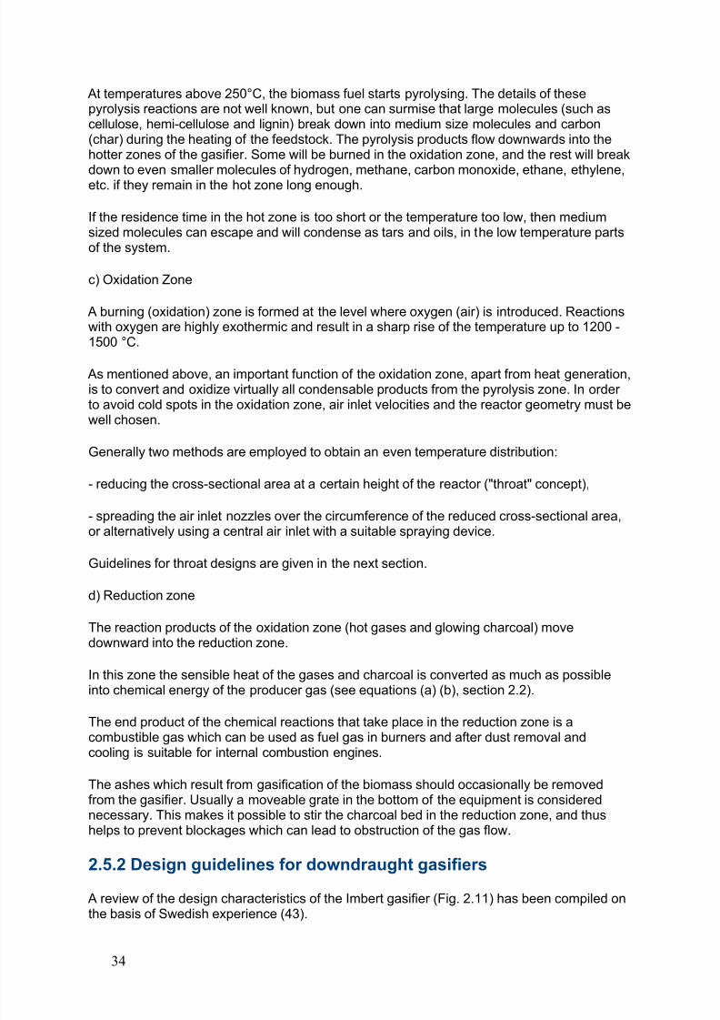
2.5.2 Design guidelines for downdraught gasifiers
A review of the design characteristics of the Imbert gasifier (Fig. 2.11) has been compiled onthe basis of Swedish experience (43).
34
8/6/2019 Gasifier Design
http://slidepdf.com/reader/full/gasifier-design 41/139
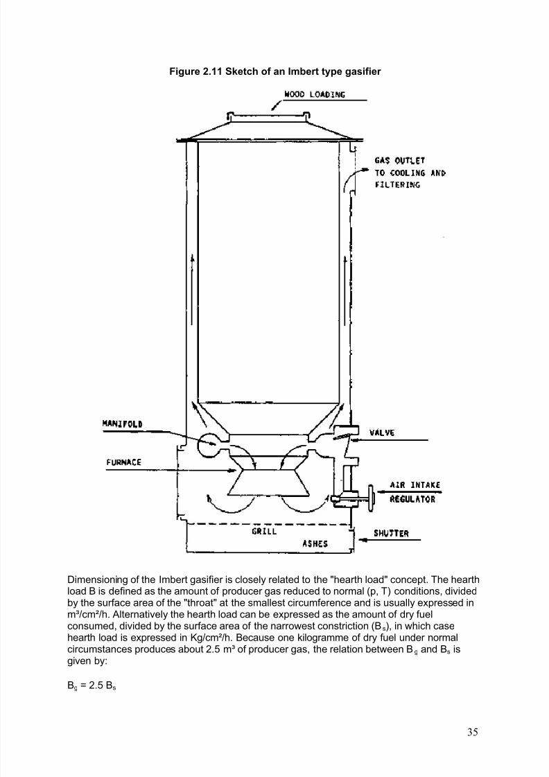
8/6/2019 Gasifier Design
http://slidepdf.com/reader/full/gasifier-design 42/139
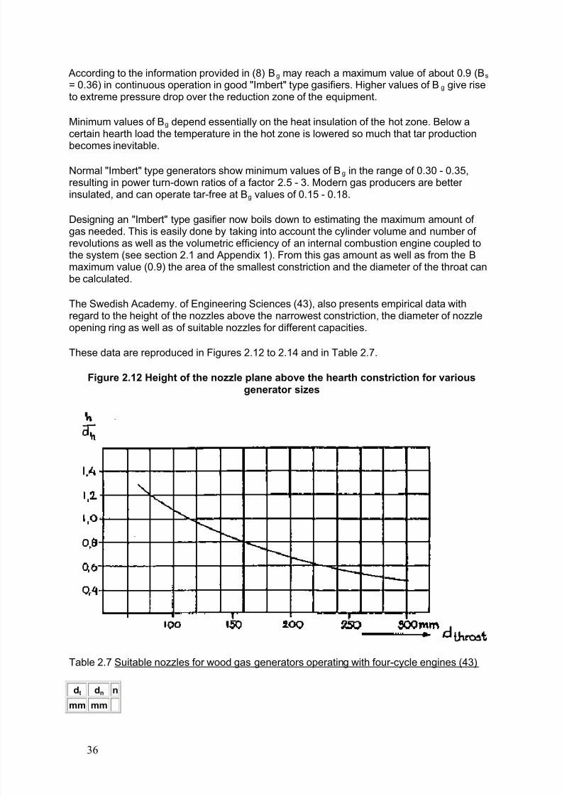
According to the information provided in (8) Bg may reach a maximum value of about 0.9 (Bs = 0.36) in continuous operation in good "Imbert" type gasifiers. Higher values of Bg give riseto extreme pressure drop over the reduction zone of the equipment.
Minimum values of Bg depend essentially on the heat insulation of the hot zone. Below acertain hearth load the temperature in the hot zone is lowered so much that tar productionbecomes inevitable.
Normal "Imbert" type generators show minimum values of Bg in the range of 0.30 - 0.35,resulting in power turn-down ratios of a factor 2.5 - 3. Modern gas producers are better insulated, and can operate tar-free at Bg values of 0.15 - 0.18.
Designing an "Imbert" type gasifier now boils down to estimating the maximum amount of gas needed. This is easily done by taking into account the cylinder volume and number of revolutions as well as the volumetric efficiency of an internal combustion engine coupled tothe system (see section 2.1 and Appendix 1). From this gas amount as well as from the Bmaximum value (0.9) the area of the smallest constriction and the diameter of the throat can
be calculated.
The Swedish Academy. of Engineering Sciences (43), also presents empirical data withregard to the height of the nozzles above the narrowest constriction, the diameter of nozzleopening ring as well as of suitable nozzles for different capacities.
These data are reproduced in Figures 2.12 to 2.14 and in Table 2.7.
Figure 2.12 Height of the nozzle plane above the hearth constriction for variousgenerator sizes
Table 2.7 Suitable nozzles for wood gas generators operating with four-cycle engines (43)
dt dn n
mm mm
36
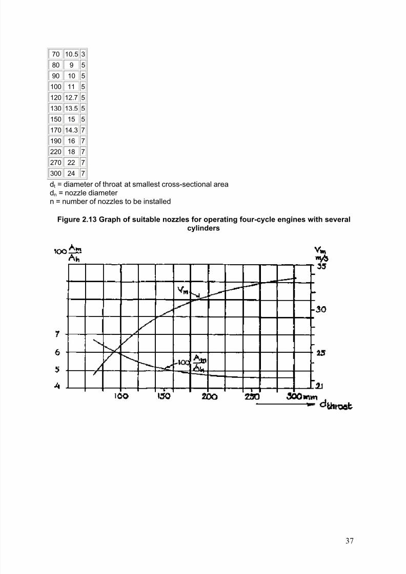
8/6/2019 Gasifier Design
http://slidepdf.com/reader/full/gasifier-design 43/139
70 10.5 3
80 9 5
90 10 5
100 11 5
120 12.7 5130 13.5 5
150 15 5
170 14.3 7
190 16 7
220 18 7
270 22 7
300 24 7
dt = diameter of throat at smallest cross-sectional areadn = nozzle diameter
n = number of nozzles to be installed
Figure 2.13 Graph of suitable nozzles for operating four-cycle engines with severalcylinders
37
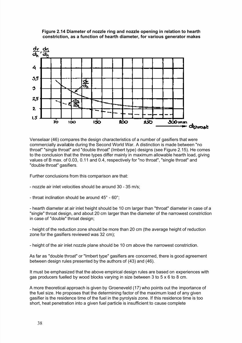
8/6/2019 Gasifier Design
http://slidepdf.com/reader/full/gasifier-design 44/139
Figure 2.14 Diameter of nozzle ring and nozzle opening in relation to hearthconstriction, as a function of hearth diameter, for various generator makes
Venselaar (46) compares the design characteristics of a number of gasifiers that werecommercially available during the Second World War. A distinction is made between "nothroat" "single throat" and "double throat" (Imbert type) designs (see Figure 2.15). He comesto the conclusion that the three types differ mainly in maximum allowable hearth load, givingvalues of B max. of 0.03, 0.11 and 0.4, respectively for "no throat", "single throat" and"double throat" gasifiers.
Further conclusions from this comparison are that:
- nozzle air inlet velocities should be around 30 - 35 m/s;
- throat inclination should be around 45° - 60°;
- hearth diameter at air inlet height should be 10 cm larger than "throat" diameter in case of a"single" throat design, and about 20 cm larger than the diameter of the narrowest constrictionin case of "double" throat design;
- height of the reduction zone should be more than 20 cm (the average height of reductionzone for the gasifiers reviewed was 32 cm);
- height of the air inlet nozzle plane should be 10 cm above the narrowest constriction.
As far as "double throat" or "Imbert type" gasifiers are concerned, there is good agreementbetween design rules presented by the authors of (43) and (46).
It must be emphasized that the above empirical design rules are based on experiences withgas producers fuelled by wood blocks varying in size between 3 to 5 x 6 to 8 cm.
A more theoretical approach is given by Groeneveld (17) who points out the importance of the fuel size. He proposes that the determining factor of the maximum load of any givengasifier is the residence time of the fuel in the pyrolysis zone. If this residence time is tooshort, heat penetration into a given fuel particle is insufficient to cause complete
38
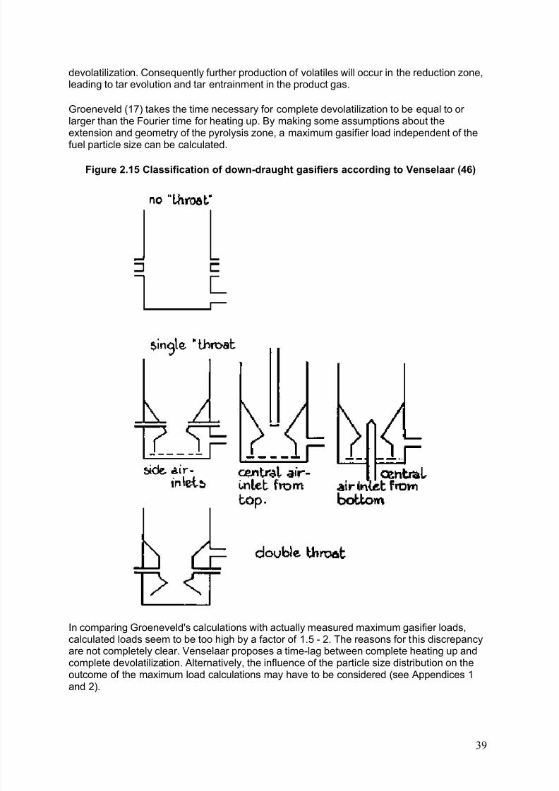
8/6/2019 Gasifier Design
http://slidepdf.com/reader/full/gasifier-design 45/139
devolatilization. Consequently further production of volatiles will occur in the reduction zone,leading to tar evolution and tar entrainment in the product gas.
Groeneveld (17) takes the time necessary for complete devolatilization to be equal to or larger than the Fourier time for heating up. By making some assumptions about theextension and geometry of the pyrolysis zone, a maximum gasifier load independent of thefuel particle size can be calculated.
Figure 2.15 Classification of down-draught gasifiers according to Venselaar (46)
In comparing Groeneveld's calculations with actually measured maximum gasifier loads,calculated loads seem to be too high by a factor of 1.5 - 2. The reasons for this discrepancyare not completely clear. Venselaar proposes a time-lag between complete heating up andcomplete devolatilization. Alternatively, the influence of the particle size distribution on theoutcome of the maximum load calculations may have to be considered (see Appendices 1and 2).
39
8/6/2019 Gasifier Design
http://slidepdf.com/reader/full/gasifier-design 46/139
2.6 Gas cleaning and cooling
Trouble free operation of an internal combustion engine using producer gas as fuel requiresa fairly clean gas (see section 2.1.3).
As has been mentioned in sections 2.3 and 2.5 well designed downdraught gasifiers are ableto meet the criteria for cleanliness at least over a fairly wide capacity range (i.e. from 20% -100% of full load). Up draught gasifiers in engine applications have to be fitted with bulky andexpensive tar separating equipment. It is however possible to get the gas from up draughtgasifiers up to specification as is reported by Leuchs (26). Methods are under developmentto reform the gas in a high temperature zone (secondary gasification), in order either to burnor crack the tars.
When suitable fuels are used, the gasifier and cleaner are well designed and the gasifier isoperated above minimum capacity, tar contamination of the gas does not present a major problem.
Gas cooling mainly serves the purpose of increasing the density of the gas in order tomaximize the amount of combustible gas entering the cylinder of the engine at each stroke. A ten percent temperature reduction of the gas increases the maximum output of the engineby almost two percent. Cooling also contributes to gas cleaning and makes it possible toavoid condensation of moisture in the gas after it is mixed with air before the engine intake.
2.6.1 Cleaning dust from the gas
The major problem in producing an engine quality gas is that of dust removal.
The amount of dust that is present in the producer gas at the outlet of the gasifier dependson the design of the equipment, the load of the gasifier and the type of fuel used.
In most gasifiers the direction of the gas stream is already reversed over 180° inside theapparatus, and this simple measure removes the coarsest dust.
The amount of dust present in the gas per m³ generally increases with the gasifier load, for the simple reason that higher loads give rise to higher gas velocities and more dust dragging.
Smaller fuel particles generally cause higher dust concentrations in the gas than do thelarger fuel blocks. The type of fuel also has an influence: hardwoods generally generate lessdust than softwoods. Maize cob gasification leads to severe dust contamination as reported
by Zijp et al. (48).
For normal type "Imbert" downdraught gasifiers, the dust leaks when using wood blocks of about 4 x 4 x 4 cm are reported to vary between 0.5 - 5 g/m³ gas (34).
Investigations of the size and size distribution of generator gas dust were undertaken byNordström (33) and the results are reproduced in Table 2.8. It is possible to separate about60% - 70% of this dust from the gas steam-by means of a well designed cyclone.
The rest (dust particles of smaller diameter) has to be removed by other means.
Table 2.8 Size distribution of producer gas dust (33)
40
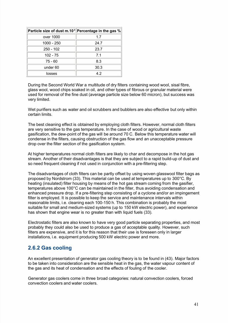
8/6/2019 Gasifier Design
http://slidepdf.com/reader/full/gasifier-design 47/139
Particle size of dust m.10-6 Percentage in the gas %
over 1000 1.7
1000 - 250 24.7
250 - 102 23.7
102 - 75 7.175 - 60 8.3
under 60 30.3
losses 4.2
During the Second World War a multitude of dry filters containing wood wool, sisal fibre,glass wool, wood chips soaked in oil, and other types of fibrous or granular material wereused for removal of the fine dust (average particle size below 60 micron), but success wasvery limited.
Wet purifiers such as water and oil scrubbers and bubblers are also effective but only within
certain limits.
The best cleaning effect is obtained by employing cloth filters. However, normal cloth filtersare very sensitive to the gas temperature. In the case of wood or agricultural wastegasification, the dew-point of the gas will be around 70 C. Below this temperature water willcondense in the filters, causing obstruction of the gas flow and an unacceptable pressuredrop over the filter section of the gasification system.
At higher temperatures normal cloth filters are likely to char and decompose in the hot gasstream. Another of their disadvantages is that they are subject to a rapid build-up of dust andso need frequent cleaning if not used in conjunction with a pre-filtering step.
The disadvantages of cloth filters can be partly offset by using woven glasswool filter bags asproposed by Nordstrom (33). This material can be used at temperatures up to 300°C. Byheating (insulated) filter housing by means of the hot gas stream coming from the gasifier,temperatures above 100°C can be maintained in the filter, thus avoiding condensation andenhanced pressure drop. If a pre-filtering step consisting of a cyclone and/or an impingementfilter is employed. It is possible to keep the service and maintenance intervals withinreasonable limits, i.e. cleaning each 100-150 h. This combination is probably the mostsuitable for small and medium-sized systems (up to 150 kW electric power), and experiencehas shown that engine wear is no greater than with liquid fuels (33).
Electrostatic filters are also known to have very good particle separating properties, and most
probably they could also be used to produce a gas of acceptable quality. However, suchfilters are expensive, and it is for this reason that their use is foreseen only in larger installations, i.e. equipment producing 500 kW electric power and more.
2.6.2 Gas cooling
An excellent presentation of generator gas cooling theory is to be found in (43). Major factorsto be taken into consideration are the sensible heat in the gas, the water vapour content of the gas and its heat of condensation and the effects of fouling of the cooler.
Generator gas coolers come in three broad categories: natural convection coolers, forced
convection coolers and water coolers.
41
8/6/2019 Gasifier Design
http://slidepdf.com/reader/full/gasifier-design 48/139
Natural convection coolers consist of a simple length of pipe. They are simple to use andclean and require no additional energy input. They can be rather bulky, though this problemcan be partly offset by using fined pipe in order to increase the conductive surface. Forcedconvection coolers are equipped with a fan which forces the cooling air to flow around thegas pipes. This type of cooler can be much smaller than the natural convection coolers. Itsdisadvantages are the extra energy input to the fan and the necessity to use gas coolingpipes of small diameters, which can lead to fouling problems. The former can in some casesbe offset by using the cooling air supplied by the engine fan.
Water coolers are available in two types, the scrubber and the heat exchanger; where awater scrubber or bubbler is used, the objective is generally to cool and clean the gas in oneand the same operation.
Scrubbers of many different types exist, but the principle is always the same: the gas isbrought in direct contact with a fluid medium (generally water) which is sprayed into the gasstream by means of a suitable nozzle device. The advantage of this system is its small size.Disadvantages are the need for fresh water, increased complexity of maintenance, and some
power consumption resulting from the use of a water pump.
The cleaning of the cooling water from phenols and other tar components is by all probabilityalso a necessary and cumbersome operation. But so far very little experiences or costcalculations for the waste water treatment are available.
It is also possible to cool the gas by means of a water cooled heat exchanger. This is asuitable method in case a source of fresh water is continuously available and the extrainvestment and power consumption of a suitable water pump can be justified.
2.7 Applications of biomass gasification
A review of gasifier applications has been published by Foley and Barnard (12), who discussthe use of gasifiers for production of fuel gas for heat generation as well as the utilization of gasifiers in combination with engines.
2.7.1 Production of fuel gas
Most gasifiers in commercial operation today are used for the production of heat, rather thanfuel for internal combustion engines, because of the less stringent requirements for gasheating value and tar content. The fundamental advantage of a gasifier close coupled to aburning system is its ability to produce higher temperatures than can be achieved with
conventional grate, combustion, liable to slagging problems at such temperatures, and inconsequence its enhancement of boiler efficiency and output.
All types of gasifiers described in Section 2.3 can provide producer gas for combustionpurposes, but for the sake of simplicity up-draught gasifiers are preferred in small systems(below 1 MW thermal power), while fluidised bed gasifiers are appropriate in power rangesabove this level.
Most conventional oil-fired installations can be converted to producer gas.
The most potential users of low-calorific fuel-gas in the future are expected to be foundamong the following industries: metallurgy, ceramic, cement, lime and pulp. In theseindustrial branches the conversion of kilns, boilers and driers from oil to fuel gas operation isin principal a quite simple operation.
42

8/6/2019 Gasifier Design
http://slidepdf.com/reader/full/gasifier-design 49/139
2.7.2 Production of mechanical or electrical power in stationaryinstallations
Gasifiers connected to stationary engines offer the possibility of using biomass to generatemechanical or electrical power in the range from a few kW up to a few MW.
Producer gas of engine quality needs a sufficiently high heating value (above 4200 Kj/m³ ),must be virtually tar and dust free in order to minimize engine wear, and should be as cool aspossible in order to maximize the engine's gas intake and power output.
It is convenient to distinguish between applications in terms of power output. Figure 2.16shows the power range of the various systems (36).
Figure 2.16 Application of biomass gasification processes
a) Large scale applications (500 kW and above)
This is the domain of the specialized fluidised bed or fixed bed installations.
The equipment is custom built and fully automized. Design and manufacture should behandled by specialized engineering and construction firms.
Equipment costs are likely to be in the range of US$ 1000 per installed kW and upwards.
b) Medium scale applications (30 -500 kW)
Fixed bed equipment fuelled by wood, charcoal and some types of agricultural wastes (maize
cobs, coconut shells) is offered by a number of European and US manufacturers. Adequate and continuing demand for this type of equipment could lead to standardization of parts and designs thus lowering production costs. For the moment quoted costs are in therange of 300 - 800 US$/kW (gasifier only) depending on type and capacity, level of automation and auxiliary equipment.
Full local manufacture is considered possible in countries possessing a well developed metalmanufacturing industry. Major parts of the installations could be manufactured in mostcountries.
Applications are foreseen in small to medium size forestry and agro-allied industries
(secondary wood industries, sawmills, coconut desiccating factories, etc.) as well as in power supply to remote communities.
c) Small-scale applications (7 - 30 kW)
This size would be appropriate for a multitude of village applications in developing countries(e.g. village maize and cereal mills, small-scale sugar crushers, looms, etc.).
The equipment must be cheap (less than 150 US$/kW), extremely reliable and should needno special operation and maintenance skills.
Designs suitable for local manufacture are tested and produced in the Philippines (13),Tanzania (48)-and a number of other countries. Documented evidence of their success is for
43

8/6/2019 Gasifier Design
http://slidepdf.com/reader/full/gasifier-design 50/139
the moment limited, and it should be stressed that training programmes for users and theorganization of some type of maintenance service are of paramount importance.
It seems that charcoal gasifiers tend to give less operational problems in this power bracketthan gasifiers fuelled by wood or agricultural residues. It is sometimes also believed thatcharcoal gasifier systems can be made cheaper than wood gasifiers systems in the 7 - 30kW power range. There is some support for this in the prices charged for vehicle gasifier systems during the Second World War (43). It is not clear however if the difference of abouttwenty percent was caused by the difference in technology or was a result of better organized production or simply a matter or different profit margins.
d) Micro scale applications (1 - 7 kW)
This is the range Used by small and medium farmers in developing countries for providingpower for irrigation systems.
Equipment must be transportable, cheap, simple and light in weight. It is quite possible that
only small locally manufactured charcoal gasifiers will be able to meet the aboverequirements.
2.7.3 Mobile applications
The use of down-draught gasifiers fuelled by wood or charcoal to power cars, lorries, buses,trains, boats and ships has proved its value and at least one European country (Sweden)maintains plans for large-scale production in case of an emergency, (see Chapter 3). Thistechnique is currently being studied for powering of tractors (Switzerland, France, Finland,Netherlands) as well as small vans and boats (Philippines) and lorries (Sri Lanka).
However mobile applications present a number of additional difficulties as compared withstationary units.
In the first place the construction needs to be as light as possible in order not to reduceexcessively the hauling capacity of the vehicle. Because the filter installations described inChapter 3 tend to be fairly heavy and voluminous, exacting demands are put on theengineering skills of designers of mobile equipment as well as on the choice of materials.
In the second place mobile applications tend to operate with fairly large variations in engine(and gasifier) load. Under a given set of circumstances (especially long idling periods) thiscan lead to tar formation and clogging of cooler/cleaners and engines, as commonlyoccurred during the Second World War.
Applications on trains and boats suffer less from weight and load constraints, and for thisreason give better results.
Engines retrofitted with gas producers show an appreciable loss of maximum power, and itwill depend very much on the geographical situation (flat or hilly terrain) as well as on theskills of the driver whether the vehicle can be operated satisfactorily.
Whether these disadvantages will be balanced by the better economy of gasifier fuelledtransport vehicles depend entirely on the local situation, especially on the cost andavailability of petrol and diesel oil.
44
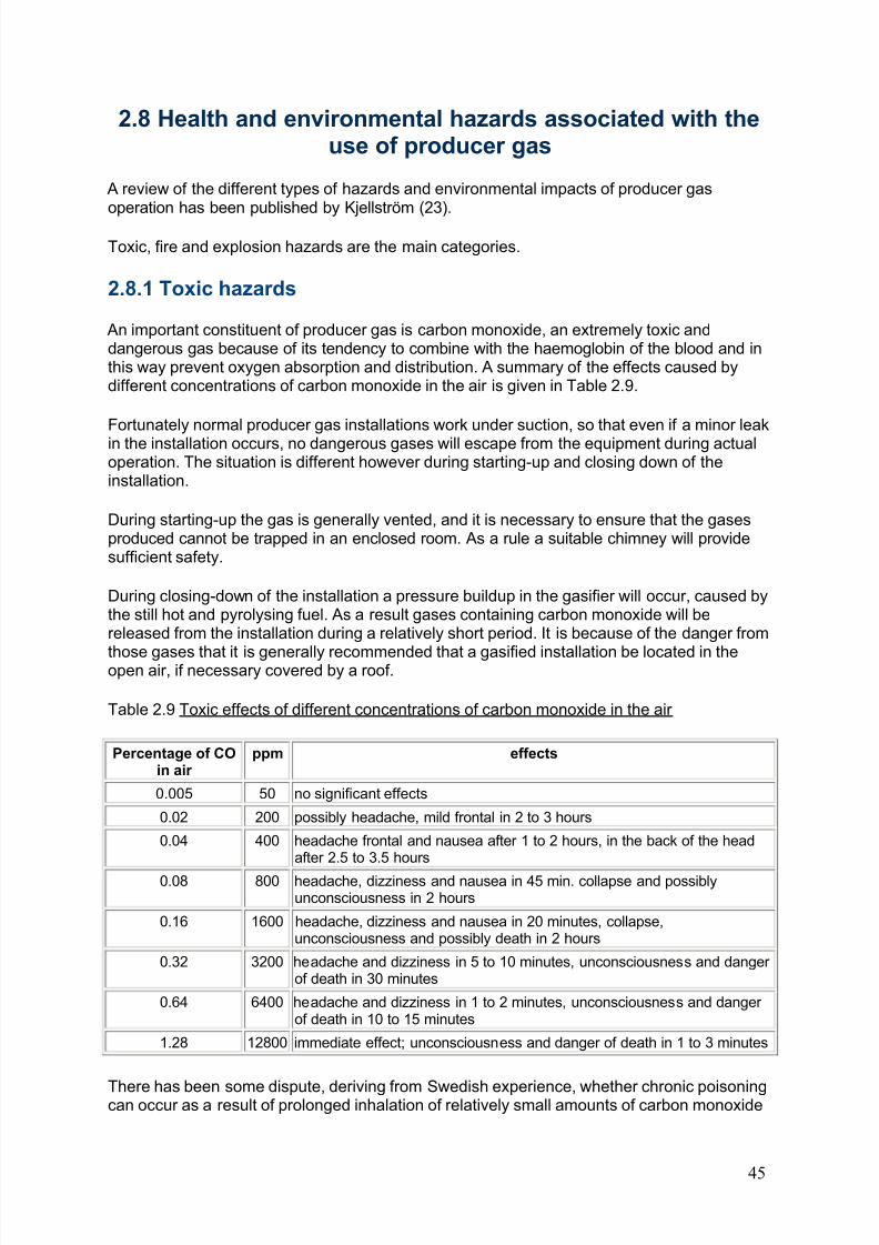
8/6/2019 Gasifier Design
http://slidepdf.com/reader/full/gasifier-design 51/139
2.8 Health and environmental hazards associated with theuse of producer gas
A review of the different types of hazards and environmental impacts of producer gasoperation has been published by Kjellström (23).
Toxic, fire and explosion hazards are the main categories.
2.8.1 Toxic hazards
An important constituent of producer gas is carbon monoxide, an extremely toxic anddangerous gas because of its tendency to combine with the haemoglobin of the blood and inthis way prevent oxygen absorption and distribution. A summary of the effects caused bydifferent concentrations of carbon monoxide in the air is given in Table 2.9.
Fortunately normal producer gas installations work under suction, so that even if a minor leakin the installation occurs, no dangerous gases will escape from the equipment during actualoperation. The situation is different however during starting-up and closing down of theinstallation.
During starting-up the gas is generally vented, and it is necessary to ensure that the gasesproduced cannot be trapped in an enclosed room. As a rule a suitable chimney will providesufficient safety.
During closing-down of the installation a pressure buildup in the gasifier will occur, caused bythe still hot and pyrolysing fuel. As a result gases containing carbon monoxide will bereleased from the installation during a relatively short period. It is because of the danger from
those gases that it is generally recommended that a gasified installation be located in theopen air, if necessary covered by a roof.
Table 2.9 Toxic effects of different concentrations of carbon monoxide in the air
Percentage of COin air
ppm effects
0.005 50 no significant effects
0.02 200 possibly headache, mild frontal in 2 to 3 hours
0.04 400 headache frontal and nausea after 1 to 2 hours, in the back of the headafter 2.5 to 3.5 hours
0.08 800 headache, dizziness and nausea in 45 min. collapse and possiblyunconsciousness in 2 hours
0.16 1600 headache, dizziness and nausea in 20 minutes, collapse,unconsciousness and possibly death in 2 hours
0.32 3200 headache and dizziness in 5 to 10 minutes, unconsciousness and danger of death in 30 minutes
0.64 6400 headache and dizziness in 1 to 2 minutes, unconsciousness and danger of death in 10 to 15 minutes
1.28 12800 immediate effect; unconsciousness and danger of death in 1 to 3 minutes
There has been some dispute, deriving from Swedish experience, whether chronic poisoningcan occur as a result of prolonged inhalation of relatively small amounts of carbon monoxide
45
8/6/2019 Gasifier Design
http://slidepdf.com/reader/full/gasifier-design 52/139
which give no acute effects. It-seems that the issue now has been resolved: no chronicsymptons can occur through carbon monoxide poisoning.
However this does not mean that the symptoms mentioned in Swedish literature (tiredness,irritability and touchiness, difficulty in sleeping) did not result from prolonged exposure toproducer gas. There is a possibility that some other compound(s) in the gas are responsiblefor the symptoms.
The above stresses again the importance of placing stationary installations in an openenvironment as well as of taking care to avoid close contact with the gases during thestarting-up and closing-down phases.
2.8.2 Fire hazards
Fire hazards can result from the following causes:
- high surface temperature of equipment;- risks of sparks during refuelling;- flames through gasifier air inlet on refuelling lid.
Risks can be considerably decreased by taking the following precautions:
- insulation of hot parts of the system;- installation of double sluice filling device;- installation of back-firing valve in gasifier inlet.
2.8.3 Explosion hazards
Explosions can occur if the gas is mixed with sufficient air to form an explosive mixture.
This could occur for several reasons:
- air leakage into the gas system;- air penetration during refuelling;- air leakage into a cold gasifier still containing gas which subsequently ignites;- backfiring from the fan exhaust burner when the system is filled with a combustible mixtureof air and gas during starting-up.
Air leakage into the gas system does not generally give rise to explosions. If a leakage
occurs in the lower part of the gasifier (as is generally the case) this will result in partialcombustion of the gas leading to higher gas outlet temperatures and a lower gas quality.
When the pyrolytic gases in the bunker section are mixed with air (as is bound to happenduring refuelling) an explosive mixture can be formed. It is not unusual for this to result insmall and relatively harmless explosions, especially when the fuel level in the bunker isrelatively low.
Risk to the operator can be obviated if the gases in the bunker section are burnt off throughthe introduction of a piece of burning paper or the like, immediately after opening the fuel lid. Another possibility is to install a double sluice type filling system.
Air leakage into a cold gasifier and immediate ignition will lead to an explosion. Cold systemsshould always be carefully ventilated before igniting the fuel.
46
8/6/2019 Gasifier Design
http://slidepdf.com/reader/full/gasifier-design 53/139
During the start-up of an installation, the gases are as a rule not passed through the entirefilter section, in order to avoid blocking the filters with the tars produced during start-up. Thefilter may thus still contain air, and after an inflammable gas is produced and led through thesometimes quite voluminous - filter section an explosive mixture can result. If the gas is nowignited at the fan outlet a backfire can occur, leading to a violent explosion in the filter section. It is fox this reason that it is advisable to fit the fan outlet with a water lock.
2.8.4 Environmental hazards
During the gasification of wood and/or agricultural residues, ashes (from the gasifier andfrom the cleaning section) and condensate (mainly water) are produced. The latter can bepolluted by phenolics and tar.
The ashes do not constitute an environmental hazard and can be disposed of in the normalway. For the tar-containing condensate the situation is different, and disposal of those from alarge number of gasifiers can have undesirable environmental effects. No hard data areavailable on the bio-degradation of the phenolic and tarry constituents of the condensates,
and the problem of disposal needs careful study.
The properties of exhaust emissions from engines run on producer gas are generallyconsidered to be acceptable, comparable to those of diesel engines.
47
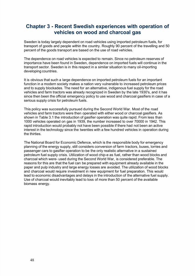
8/6/2019 Gasifier Design
http://slidepdf.com/reader/full/gasifier-design 54/139
Chapter 3 - Recent Swedish experiences with operation of vehicles on wood and charcoal gas
Sweden is today largely dependent on road vehicles using imported petroleum fuels, for transport of goods and people within the country. Roughly 90 percent of the travelling and 50percent of the goods transport are based on the use of road vehicles.
The dependence on road vehicles is expected to remain. Since no petroleum reserves of importance have been found in Sweden, dependence on imported fuels will continue in thetransport sector. Sweden is in this respect in a similar situation to many oil-importingdeveloping countries.
It is obvious that such a large dependence on imported petroleum fuels for an importantfunction in a modern society makes a nation very vulnerable to increased petroleum pricesand to supply blockades. The need for an alternative, indigenous fuel supply for the roadvehicles and farm tractors was already recognized in Sweden by the late 1930's, and it has
since then been the official emergency policy to use wood and charcoal gasifiers in case of aserious supply crisis for petroleum fuels.
This policy was successfully pursued during the Second World War. Most of the roadvehicles and farm tractors were then operated with either wood or charcoal gasifiers. Asshown in Table 3.1 the introduction of gasifier operation was quite rapid. From less than1000 vehicles operated on gas in 1939, the number increased to over 70000 in 1942. Thisrapid introduction would probably not have been possible if there had not been an activeinterest in the technology since the twenties with a few hundred vehicles in operation duringthe thirties.
The National Board for Economic Defence, which is the responsible body for emergencyplanning of the energy supply, still considers conversion of farm tractors, buses, lorries andpassenger cars to gasifier operation to be the only realistic alternative in a sustainedpetroleum fuel supply crisis. Utilization of wood chip-e as fuel, rather than wood blocks andcharcoal which were- used during the Second World War, is considered preferable. Thereasons for this are that the fuel can be prepared with equipment already available in thepaper and pulp industry and large energy losses are avoided. The utilization of wood blocksand charcoal would require investment in new equipment for fuel preparation. This wouldlead to economic disadvantages and delays in the introduction of the alternative fuel supply.Use of charcoal would inevitably lead to loss of more than 50 percent of the availablebiomass energy.
48
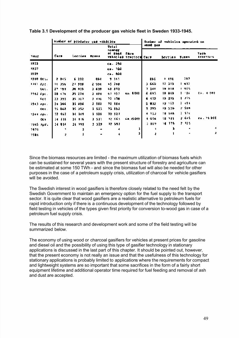
8/6/2019 Gasifier Design
http://slidepdf.com/reader/full/gasifier-design 55/139
Table 3.1 Development of the producer gas vehicle fleet in Sweden 1933-1945.
Since the biomass resources are limited - the maximum utilization of biomass fuels whichcan be sustained for several years with the present structure of forestry and agriculture canbe estimated at some 150 TWh - and since the biomass fuel will also be needed for other purposes in the case of a petroleum supply crisis, utilization of charcoal for vehicle gasifiers
will be avoided.
The Swedish interest in wood gasifiers is therefore closely related to the need felt by theSwedish Government to maintain an emergency option for the fuel supply to the transportsector. It is quite clear that wood gasifiers are a realistic alternative to petroleum fuels for rapid introduction only if there is a continuous development of the technology followed byfield testing in vehicles of the types given first priority for conversion to-wood gas in case of apetroleum fuel supply crisis.
The results of this research and development work and some of the field testing will besummarized below.
The economy of using wood or charcoal gasifiers for vehicles at present prices for gasolineand diesel oil and the possibility of using this type of gasifier technology in stationaryapplications is discussed in the last part of this chapter. It should be pointed out, however,that the present economy is not really an issue and that the usefulness of this technology for stationary applications is probably limited to applications where the requirements for compactand lightweight systems are so important that some sacrifices in the form of a fairly shortequipment lifetime and additional operator time required for fuel feeding and removal of ashand dust are accepted.
49
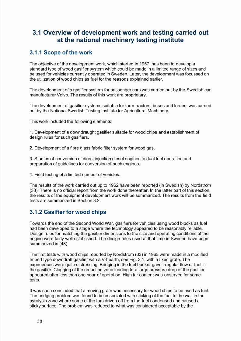
8/6/2019 Gasifier Design
http://slidepdf.com/reader/full/gasifier-design 56/139
3.1 Overview of development work and testing carried outat the national machinery testing institute
3.1.1 Scope of the work
The objective of the development work, which started in 1957, has been to develop astandard type of wood gasifier system which could be made in a limited range of sizes andbe used for vehicles currently operated in Sweden. Later, the development was focussed onthe utilization of wood chips as fuel for the reasons explained earlier.
The development of a gasifier system for passenger cars was carried out-by the Swedish car manufacturer Volvo. The results of this work are proprietary.
The development of gasifier systems suitable for farm tractors, buses and lorries, was carriedout by the National Swedish Testing Institute for Agricultural Machinery.
This work included the following elements:
1. Development of a downdraught gasifier suitable for wood chips and establishment of design rules for such gasifiers.
2. Development of a fibre glass fabric filter system for wood gas.
3. Studies of conversion of direct injection diesel engines to dual fuel operation andpreparation of guidelines for conversion of such engines.
4. Field testing of a limited number of vehicles.
The results of the work carried out up to 1962 have been reported (in Swedish) by Nordstrom(33). There is no official report from the work done thereafter. In the latter part of this section,the results of the equipment development work will be summarized. The results from the fieldtests are summarized in Section 3.2.
3.1.2 Gasifier for wood chips
Towards the end of the Second World War, gasifiers for vehicles using wood blocks as fuelhad been developed to a stage where the technology appeared to be reasonably reliable.Design rules for matching the gasifier dimensions to the size and operating conditions of the
engine were fairly well established. The design rules used at that time in Sweden have beensummarized in (43).
The first tests with wood chips reported by Nordstrom (33) in 1963 were made in a modifiedImbert type downdraft gasifier with a V-hearth, see Fig. 3.1, with a fixed grate. Theexperiences were quite distressing. Bridging in the fuel bunker gave irregular flow of fuel inthe gasifier. Clogging of the reduction zone leading to a large pressure drop of the gasifier appeared after less than one hour of operation. High tar content was observed for sometests.
It was soon concluded that a moving grate was necessary for wood chips to be used as fuel.The bridging problem was found to be associated with sticking of the fuel to the wall in thepyrolysis zone where some of the tars driven off from the fuel condensed and caused asticky surface. The problem was reduced to what was considered acceptable by the
50
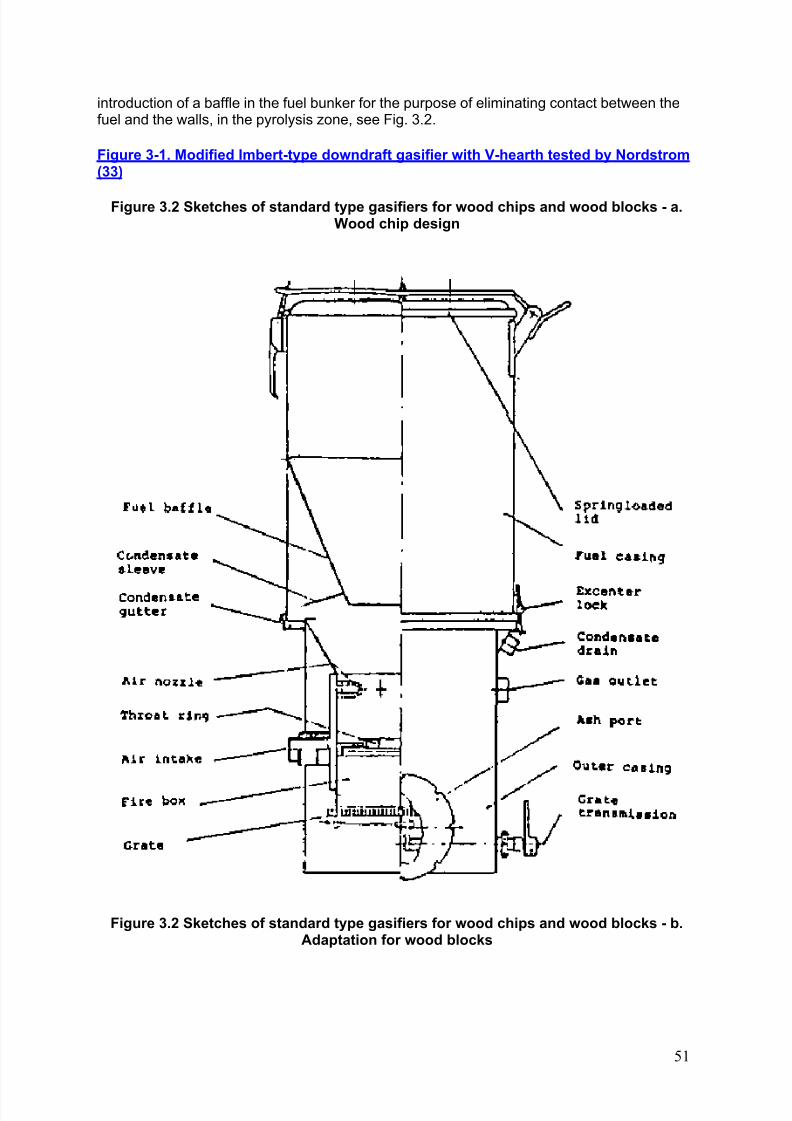
8/6/2019 Gasifier Design
http://slidepdf.com/reader/full/gasifier-design 57/139
introduction of a baffle in the fuel bunker for the purpose of eliminating contact between thefuel and the walls, in the pyrolysis zone, see Fig. 3.2.
Figure 3-1. Modified Imbert-type downdraft gasifier with V-hearth tested by Nordstrom(33)
Figure 3.2 Sketches of standard type gasifiers for wood chips and wood blocks - a.Wood chip design
Figure 3.2 Sketches of standard type gasifiers for wood chips and wood blocks - b.Adaptation for wood blocks
51
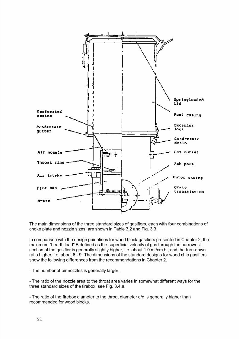
8/6/2019 Gasifier Design
http://slidepdf.com/reader/full/gasifier-design 58/139
The main dimensions of the three standard sizes of gasifiers, each with four combinations of choke plate and nozzle sizes, are shown in Table 3.2 and Fig. 3.3.
In comparison with the design guidelines for wood block gasifiers presented in Chapter 2, themaximum "hearth load" B defined as the superficial velocity of gas through the narrowestsection of the gasifier is generally slightly higher, i.e. about 1.0 m /cm h., and the turn-downratio higher, i.e. about 6 - 9. The dimensions of the standard designs for wood chip gasifiersshow the following differences from the recommendations in Chapter 2.
- The number of air nozzles is generally larger.
- The ratio of the nozzle area to the throat area varies in somewhat different ways for thethree standard sizes of the firebox, see Fig. 3.4.a.
- The ratio of the firebox diameter to the throat diameter d/d is generally higher thanrecommended for wood blocks.
52
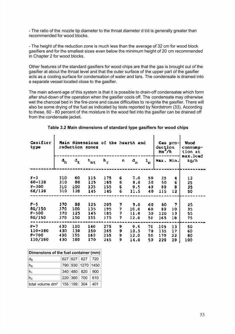
8/6/2019 Gasifier Design
http://slidepdf.com/reader/full/gasifier-design 59/139
- The ratio of the nozzle tip diameter to the throat diameter d t/d is generally greater thanrecommended for wood blocks.
- The height of the reduction zone is much less than the average of 32 cm for wood blockgasifiers and for the smallest sizes even below the minimum height of 20 cm recommendedin Chapter 2 for wood blocks.
Other features of the standard gasifiers for wood chips are that the gas is brought out of thegasifier at about the throat level and that the outer surface of the upper part of the gasifier acts as a cooling surface for condensation of water and tars. The condensate is drained intoa separate vessel located close to the gasifier.
The main advent-age of this system is that it is possible to drain-off condensates which formafter shut-down of the operation when the gasifier cools off. The condensate may otherwisewet the charcoal bed in the fire-zone and cause difficulties to re-ignite the gasifier. There willalso be some drying of the fuel as indicated by tests reported by Nordstrom (33). Accordingto these, 60 - 80 percent of the moisture in the wood fed into the gasifier can be drained off
from the condensate jacket.
Table 3.2 Main dimensions of standard type gasifiers for wood chips
Dimensions of the fuel container (mm)
dB 627 627 627 720
hB 790 930 1270 1450
h1 340 480 820 900
h2 220 360 700 610
total volume dm³ 155 199 304 401
53
8/6/2019 Gasifier Design
http://slidepdf.com/reader/full/gasifier-design 60/139
Figure 3.3 Main dimensions of standard type gasifiers for wood chips
54
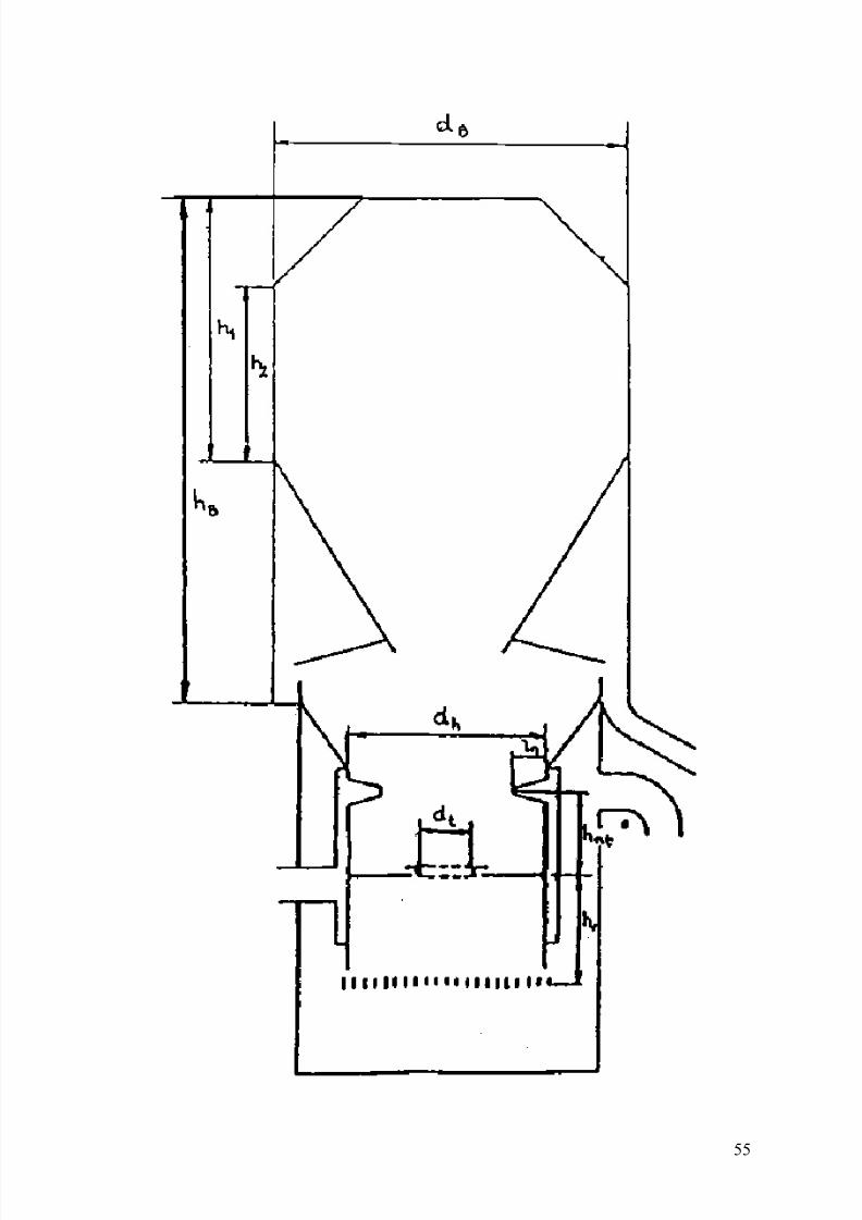
8/6/2019 Gasifier Design
http://slidepdf.com/reader/full/gasifier-design 61/139
55
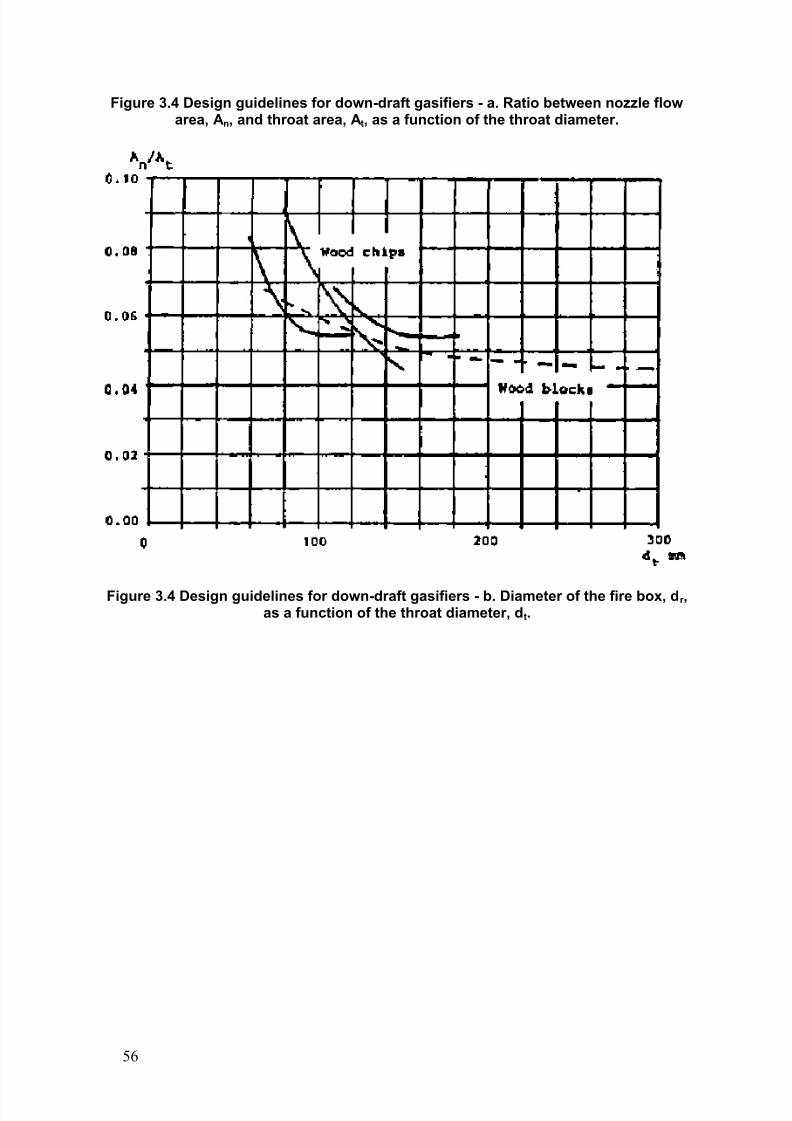
8/6/2019 Gasifier Design
http://slidepdf.com/reader/full/gasifier-design 62/139
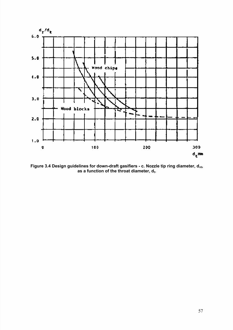
8/6/2019 Gasifier Design
http://slidepdf.com/reader/full/gasifier-design 63/139
Figure 3.4 Design guidelines for down-draft gasifiers - c. Nozzle tip ring diameter, d nt,as a function of the throat diameter, d
t.
57
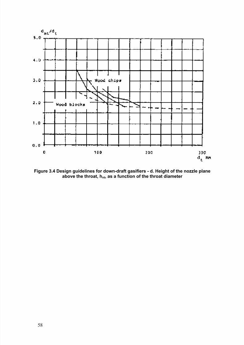
8/6/2019 Gasifier Design
http://slidepdf.com/reader/full/gasifier-design 64/139
Figure 3.4 Design guidelines for down-draft gasifiers - d. Height of the nozzle planeabove the throat, hnt, as a function of the throat diameter
58
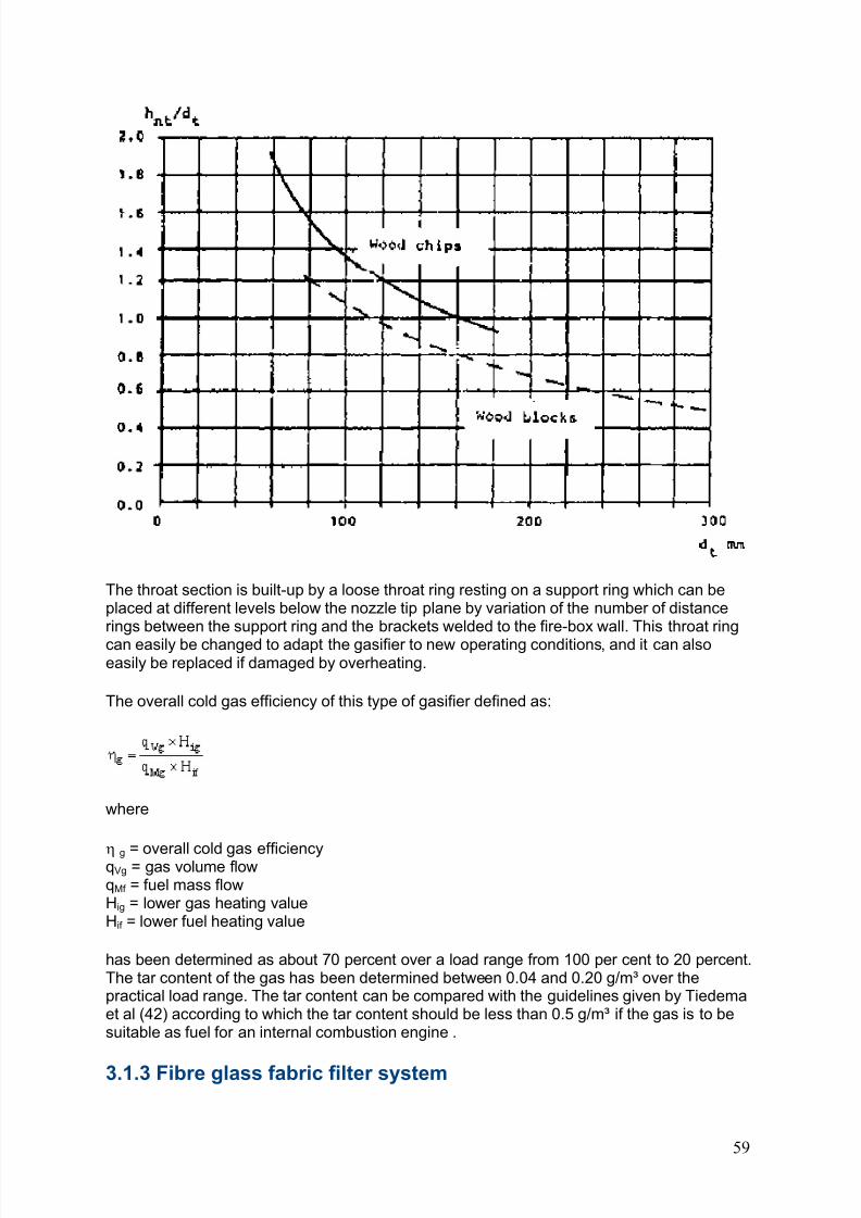
8/6/2019 Gasifier Design
http://slidepdf.com/reader/full/gasifier-design 65/139
The throat section is built-up by a loose throat ring resting on a support ring which can beplaced at different levels below the nozzle tip plane by variation of the number of distancerings between the support ring and the brackets welded to the fire-box wall. This throat ring
can easily be changed to adapt the gasifier to new operating conditions, and it can alsoeasily be replaced if damaged by overheating.
The overall cold gas efficiency of this type of gasifier defined as:
where
g = overall cold gas efficiencyqVg = gas volume flowqMf = fuel mass flowHig = lower gas heating valueHif = lower fuel heating value
has been determined as about 70 percent over a load range from 100 per cent to 20 percent.The tar content of the gas has been determined between 0.04 and 0.20 g/m³ over thepractical load range. The tar content can be compared with the guidelines given by Tiedemaet al (42) according to which the tar content should be less than 0.5 g/m³ if the gas is to besuitable as fuel for an internal combustion engine .
3.1.3 Fibre glass fabric filter system
59
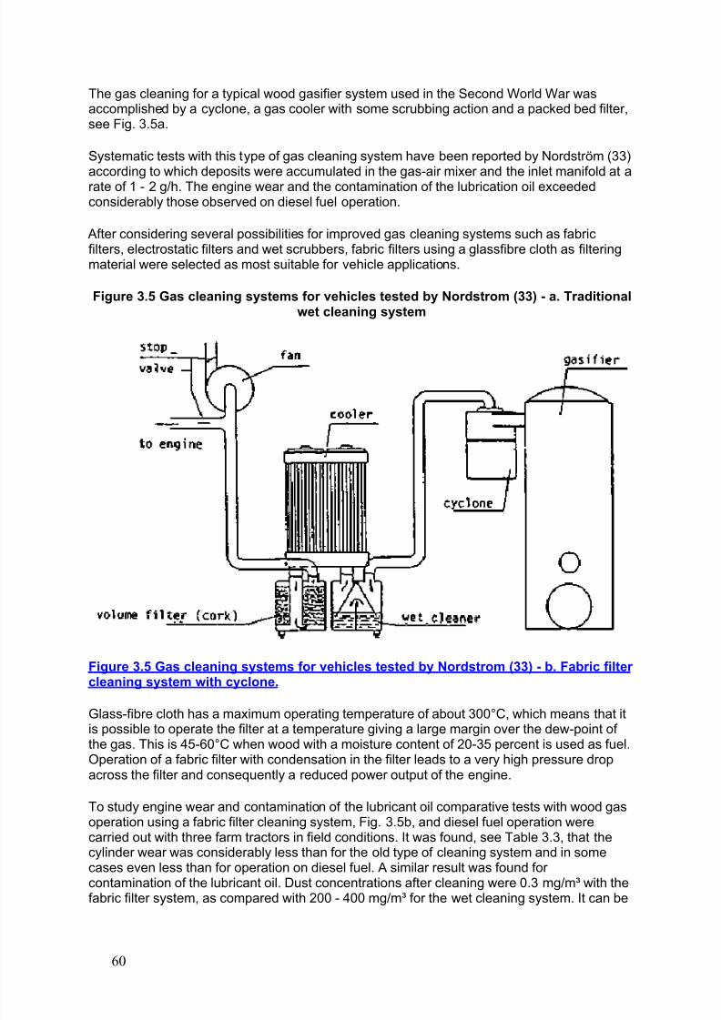
8/6/2019 Gasifier Design
http://slidepdf.com/reader/full/gasifier-design 66/139
The gas cleaning for a typical wood gasifier system used in the Second World War wasaccomplished by a cyclone, a gas cooler with some scrubbing action and a packed bed filter,see Fig. 3.5a.
Systematic tests with this type of gas cleaning system have been reported by Nordström (33)according to which deposits were accumulated in the gas-air mixer and the inlet manifold at arate of 1 - 2 g/h. The engine wear and the contamination of the lubrication oil exceededconsiderably those observed on diesel fuel operation.
After considering several possibilities for improved gas cleaning systems such as fabricfilters, electrostatic filters and wet scrubbers, fabric filters using a glassfibre cloth as filteringmaterial were selected as most suitable for vehicle applications.
Figure 3.5 Gas cleaning systems for vehicles tested by Nordstrom (33) - a. Traditionalwet cleaning system
Figure 3.5 Gas cleaning systems for vehicles tested by Nordstrom (33) - b. Fabric filter cleaning system with cyclone.
Glass-fibre cloth has a maximum operating temperature of about 300°C, which means that itis possible to operate the filter at a temperature giving a large margin over the dew-point of the gas. This is 45-60°C when wood with a moisture content of 20-35 percent is used as fuel.Operation of a fabric filter with condensation in the filter leads to a very high pressure dropacross the filter and consequently a reduced power output of the engine.
To study engine wear and contamination of the lubricant oil comparative tests with wood gasoperation using a fabric filter cleaning system, Fig. 3.5b, and diesel fuel operation werecarried out with three farm tractors in field conditions. It was found, see Table 3.3, that thecylinder wear was considerably less than for the old type of cleaning system and in somecases even less than for operation on diesel fuel. A similar result was found for contamination of the lubricant oil. Dust concentrations after cleaning were 0.3 mg/m³ with thefabric filter system, as compared with 200 - 400 mg/m³ for the wet cleaning system. It can be
60
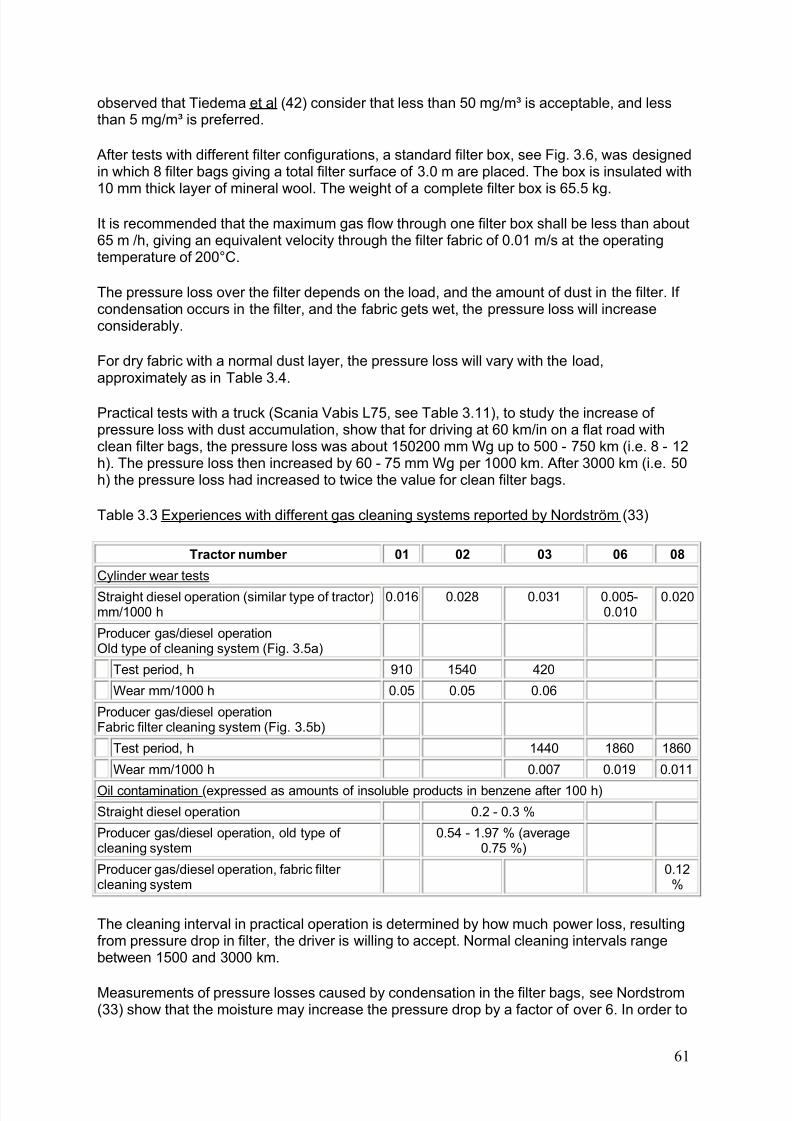
8/6/2019 Gasifier Design
http://slidepdf.com/reader/full/gasifier-design 67/139
observed that Tiedema et al (42) consider that less than 50 mg/m³ is acceptable, and lessthan 5 mg/m³ is preferred.
After tests with different filter configurations, a standard filter box, see Fig. 3.6, was designedin which 8 filter bags giving a total filter surface of 3.0 m are placed. The box is insulated with10 mm thick layer of mineral wool. The weight of a complete filter box is 65.5 kg.
It is recommended that the maximum gas flow through one filter box shall be less than about65 m /h, giving an equivalent velocity through the filter fabric of 0.01 m/s at the operatingtemperature of 200°C.
The pressure loss over the filter depends on the load, and the amount of dust in the filter. If condensation occurs in the filter, and the fabric gets wet, the pressure loss will increaseconsiderably.
For dry fabric with a normal dust layer, the pressure loss will vary with the load,approximately as in Table 3.4.
Practical tests with a truck (Scania Vabis L75, see Table 3.11), to study the increase of pressure loss with dust accumulation, show that for driving at 60 km/in on a flat road withclean filter bags, the pressure loss was about 150200 mm Wg up to 500 - 750 km (i.e. 8 - 12h). The pressure loss then increased by 60 - 75 mm Wg per 1000 km. After 3000 km (i.e. 50h) the pressure loss had increased to twice the value for clean filter bags.
Table 3.3 Experiences with different gas cleaning systems reported by Nordström (33)
Tractor number 01 02 03 06 08
Cylinder wear tests
Straight diesel operation (similar type of tractor)mm/1000 h
0.016 0.028 0.031 0.005-0.010
0.020
Producer gas/diesel operationOld type of cleaning system (Fig. 3.5a)
Test period, h 910 1540 420
Wear mm/1000 h 0.05 0.05 0.06
Producer gas/diesel operationFabric filter cleaning system (Fig. 3.5b)
Test period, h 1440 1860 1860
Wear mm/1000 h 0.007 0.019 0.011
Oil contamination (expressed as amounts of insoluble products in benzene after 100 h)Straight diesel operation 0.2 - 0.3 %
Producer gas/diesel operation, old type of cleaning system
0.54 - 1.97 % (average0.75 %)
Producer gas/diesel operation, fabric filter cleaning system
0.12%
The cleaning interval in practical operation is determined by how much power loss, resultingfrom pressure drop in filter, the driver is willing to accept. Normal cleaning intervals rangebetween 1500 and 3000 km.
Measurements of pressure losses caused by condensation in the filter bags, see Nordstrom(33) show that the moisture may increase the pressure drop by a factor of over 6. In order to
61
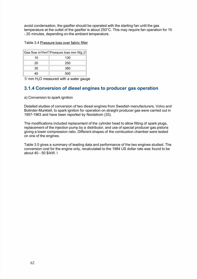
8/6/2019 Gasifier Design
http://slidepdf.com/reader/full/gasifier-design 68/139
avoid condensation, the gasifier should be operated with the starting fan until the gastemperature at the outlet of the gasifier is about 250°C. This may require fan operation for 15- 20 minutes, depending on-the ambient temperature.
Table 3.4 Pressure loss over fabric filter
Gas flow m³/hm² Pressure loss mm Wg 1/
10 130
20 250
30 380
40 500
1/ mm H2O measured with a water gauge
3.1.4 Conversion of diesel engines to producer gas operation
a) Conversion to spark ignition
Detailed studies of conversion of two diesel engines from Swedish manufacturers, Volvo andBolinder-Munktell, to spark ignition for operation on straight producer gas were carried out in1957-1963 and have been reported by Nordstrom (33).
The modifications included replacement of the cylinder head to allow fitting of spark plugs,replacement of the injection pump by a distributor, and use of special producer gas pistonsgiving a lower compression ratio. Different shapes of the combustion chamber were testedon one of the engines.
Table 3.5 gives a summary of leading data and performance of the two engines studied. Theconversion cost for the engine only, recalculated to the 1984 US dollar rate was found to beabout 40 - 50 $/kW. l
62
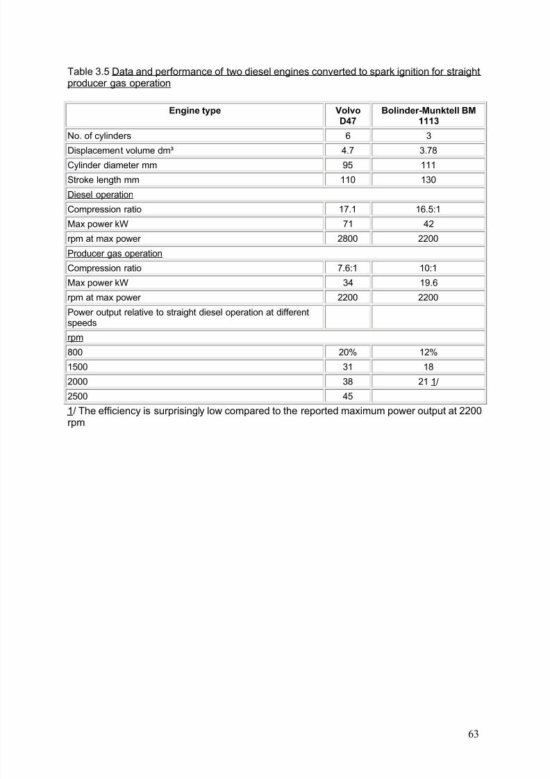
8/6/2019 Gasifier Design
http://slidepdf.com/reader/full/gasifier-design 69/139
Table 3.5 Data and performance of two diesel engines converted to spark ignition for straightproducer gas operation
Engine type VolvoD47
Bolinder-Munktell BM1113
No. of cylinders 6 3Displacement volume dm³ 4.7 3.78
Cylinder diameter mm 95 111
Stroke length mm 110 130
Diesel operation
Compression ratio 17.1 16.5:1
Max power kW 71 42
rpm at max power 2800 2200
Producer gas operation
Compression ratio 7.6:1 10:1Max power kW 34 19.6
rpm at max power 2200 2200
Power output relative to straight diesel operation at differentspeeds
rpm
800 20% 12%
1500 31 18
2000 38 21 1/
2500 45
1/ The efficiency is surprisingly low compared to the reported maximum power output at 2200rpm
63
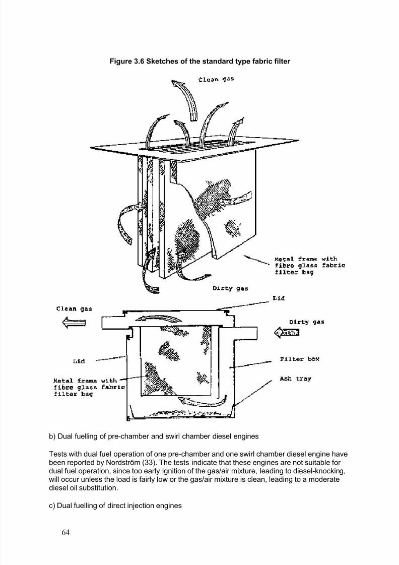
8/6/2019 Gasifier Design
http://slidepdf.com/reader/full/gasifier-design 70/139
Figure 3.6 Sketches of the standard type fabric filter
b) Dual fuelling of pre-chamber and swirl chamber diesel engines
Tests with dual fuel operation of one pre-chamber and one swirl chamber diesel engine havebeen reported by Nordström (33). The tests indicate that these engines are not suitable for dual fuel operation, since too early ignition of the gas/air mixture, leading to diesel-knocking,will occur unless the load is fairly low or the gas/air mixture is clean, leading to a moderatediesel oil substitution.
c) Dual fuelling of direct injection engines
64
8/6/2019 Gasifier Design
http://slidepdf.com/reader/full/gasifier-design 71/139
Studies of the performance of direct injection diesel engines operated in a dual fuel modewith a minimum diesel oil injection, have been carried out at the National Swedish TestingInstitute for Agricultural Machinery. The tests are still going on. A list of the tested vehicles isgiven in Tables 3.10 and 3.11.
The experience is that the modifications required are generally simple and limited to:
- installation of a control lever for obtaining low injection quantities and maintaining thepossibility for normal injection by straight diesel operation;
- modification of the injection pump to provide suitable injection characteristics (constantinjection per stroke at varying engine speed);
- advancing the injection timing.
The direct injection engines will normally operate well in dual fuel mode with a compressionratio of 1:16 to 1:16.5. Diesel knocking may occur in some cases. The compression ratio
must then be reduced by use of double cylinder head gaskets. The reduction of the injectionamount is accomplished for in-line pumps by mechanically constraining the movement of thecontrol rod.
Suitable injection characteristics for such pumps are obtained by use of a specially designeddelivery valve, see Nordstrom (33). For distributor pumps, the flow is reduced by adjustmentof the metering valve. Distributor pumps may suffer from inadequate cooling and lubrication if the injection flow is reduced since there will be a very small supply of cold fuel to the pump.This can be remedied by leading the excess flow from the pump to the fuel tank rather thanrecirculating it to the filter, see Fig. 3.7. Depending on the injector design it may benecessary to modify the mounting of the injectors or to replace the injectors in order to avoid
coking as a result of high injector temperature caused by the low injection flow. An exampleof such modification is given in section 3.2.2.
The studies of the effects of injection timing on power output indicate that the injection timingis not very important for engine speeds below 1200 rpm, and that advancing the injectiontiming grows more important as the speed increases. Injection advancement beyond 35 - 40°was observed to give pressure fluctuations.- Compromises between maximum power at highrpm and disturbance free combustion at low rpm may be necessary. It is recommended thatthe injection timing setting for dual fuel operation be determined by bench-tests for each typeof engine.
Table 3.6 shows examples of performance data determined in laboratory tests for two direct
injection engines operated on dual fuel. The full power efficiency of the engines is about 35percent. The diesel oil substitution is between 80 percent and 90 percent.
The power loss in dual fuel operation was found to be 10 - 38 percent, see Tables 3.10 and3.11.
3.1.5 Tests with different fuels
a) Fuel specifications
The practical tests with gasifiers for wood chips developed at the National Swedish Testing
Institute for Agricultural Machinery have been carried out with fuel moisture contents (wetbasis) of 10 - 20 percent. The upper limit for the moisture content for acceptable gas quality
65
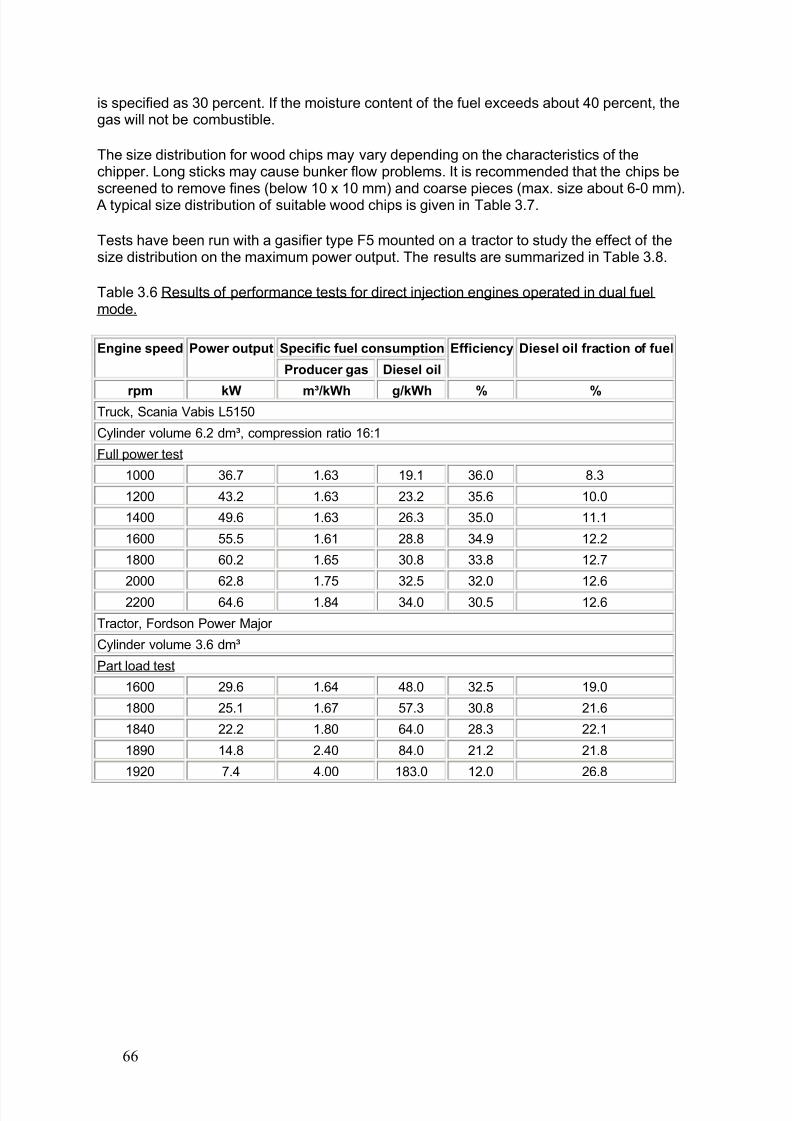
8/6/2019 Gasifier Design
http://slidepdf.com/reader/full/gasifier-design 72/139
is specified as 30 percent. If the moisture content of the fuel exceeds about 40 percent, thegas will not be combustible.
The size distribution for wood chips may vary depending on the characteristics of thechipper. Long sticks may cause bunker flow problems. It is recommended that the chips bescreened to remove fines (below 10 x 10 mm) and coarse pieces (max. size about 6-0 mm). A typical size distribution of suitable wood chips is given in Table 3.7.
Tests have been run with a gasifier type F5 mounted on a tractor to study the effect of thesize distribution on the maximum power output. The results are summarized in Table 3.8.
Table 3.6 Results of performance tests for direct injection engines operated in dual fuelmode.
Specific fuel consumptionEngine speed Power output
Producer gas Diesel oil
Efficiency Diesel oil fraction of fuel
rpm kW m³/kWh g/kWh % % Truck, Scania Vabis L5150
Cylinder volume 6.2 dm³, compression ratio 16:1
Full power test
1000 36.7 1.63 19.1 36.0 8.3
1200 43.2 1.63 23.2 35.6 10.0
1400 49.6 1.63 26.3 35.0 11.1
1600 55.5 1.61 28.8 34.9 12.2
1800 60.2 1.65 30.8 33.8 12.7
2000 62.8 1.75 32.5 32.0 12.6
2200 64.6 1.84 34.0 30.5 12.6
Tractor, Fordson Power Major
Cylinder volume 3.6 dm³
Part load test
1600 29.6 1.64 48.0 32.5 19.0
1800 25.1 1.67 57.3 30.8 21.6
1840 22.2 1.80 64.0 28.3 22.1
1890 14.8 2.40 84.0 21.2 21.8
1920 7.4 4.00 183.0 12.0 26.8
66
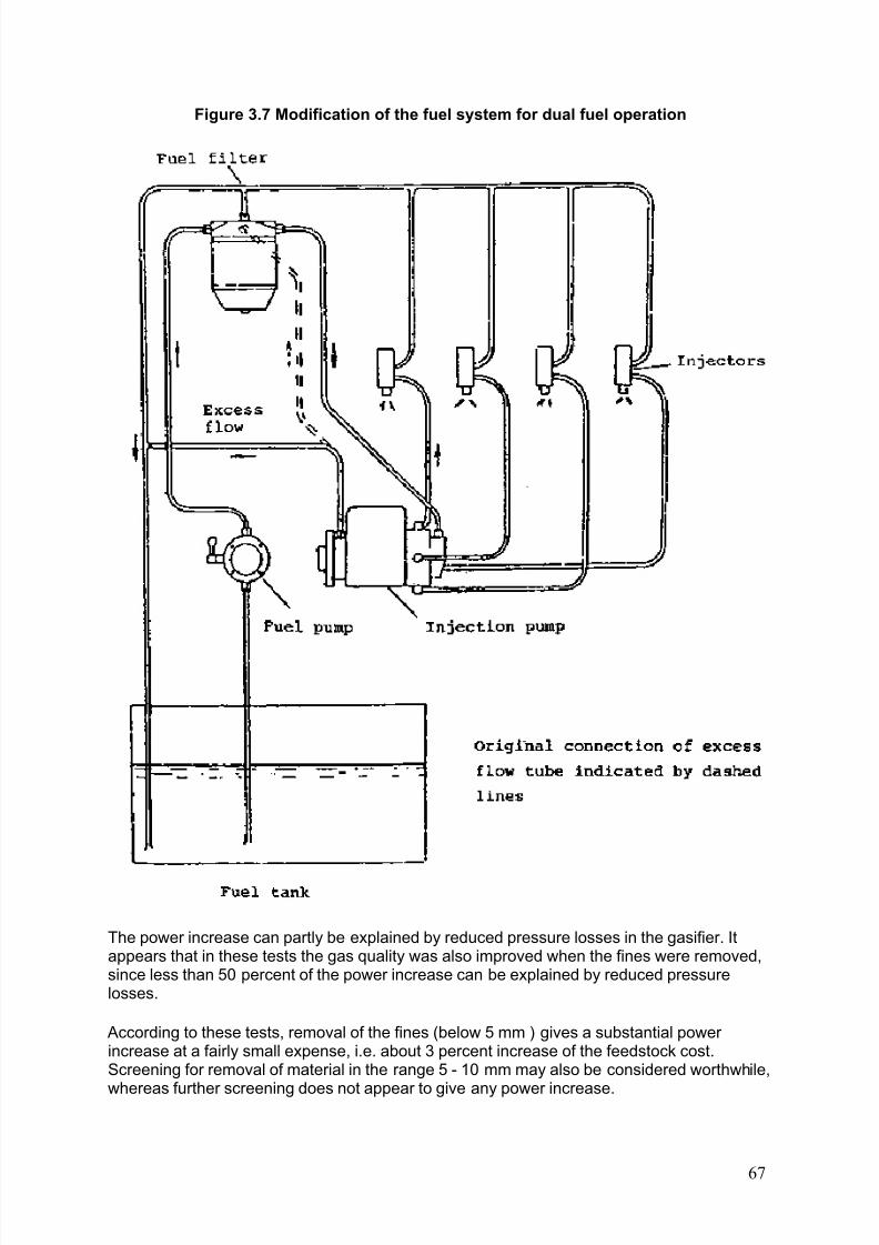
8/6/2019 Gasifier Design
http://slidepdf.com/reader/full/gasifier-design 73/139
Figure 3.7 Modification of the fuel system for dual fuel operation
The power increase can partly be explained by reduced pressure losses in the gasifier. Itappears that in these tests the gas quality was also improved when the fines were removed,since less than 50 percent of the power increase can be explained by reduced pressurelosses.
According to these tests, removal of the fines (below 5 mm ) gives a substantial power increase at a fairly small expense, i.e. about 3 percent increase of the feedstock cost.Screening for removal of material in the range 5 - 10 mm may also be considered worthwhile,
whereas further screening does not appear to give any power increase.
67
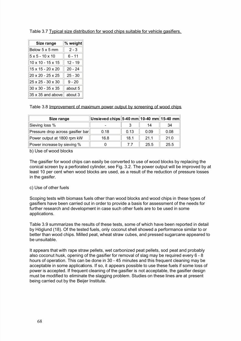
8/6/2019 Gasifier Design
http://slidepdf.com/reader/full/gasifier-design 74/139
Table 3.7 Typical size distribution for wood chips suitable for vehicle gasifiers.
Size range % weight
Below 5 x 5 mm 2 - 3
5 x 5 - 10 x 10 6 - 11
10 x 10 - 15 x 15 12 - 19
15 x 15 - 20 x 20 20 - 24
20 x 20 - 25 x 25 25 - 30
25 x 25 - 30 x 30 9 - 20
30 x 30 - 35 x 35 about 5
35 x 35 and above about 3
Table 3.8 Improvement of maximum power output by screening of wood chips
Size range Unsieved chips 5-40 mm 10-40 mm 15-40 mm Sieving loss % - 3 14 34
Pressure drop across gasifier bar 0.18 0.13 0.09 0.08
Power output at 1800 rpm kW 16.8 18.1 21.1 21.0
Power increase by sieving % 0 7.7 25.5 25.5
b) Use of wood blocks
The gasifier for wood chips can easily be converted to use of wood blocks by replacing theconical screen by a perforated cylinder, see Fig. 3.2. The power output will be improved by atleast 10 per cent when wood blocks are used, as a result of the reduction of pressure losses
in the gasifer.c) Use of other fuels
Scoping tests with biomass fuels other than wood blocks and wood chips in these types of gasifiers have been carried out in order to provide a basis for assessment of the needs for further research and development in case such other fuels are to be used in someapplications.
Table 3.9 summarizes the results of these tests, some of which have been reported in detailby Höglund (18). Of the tested fuels, only coconut shell showed a performance similar to or better than wood chips. Milled peat, wheat straw cubes, and pressed sugarcane appeared to
be unsuitable.
It appears that with rape straw pellets, wet carbonized peat pellets, sod peat and probablyalso coconut husk, opening of the gasifier for removal of slag may be required every 6 - 8hours of operation. This can be done in 30 - 45 minutes and this frequent cleaning may beacceptable in some applications. If so, it appears possible to use these fuels if some loss of power is accepted. If frequent cleaning of the gasifier is not acceptable, the gasifier designmust be modified to eliminate the slagging problem. Studies on these lines are at presentbeing carried out by the Beijer Institute.
68
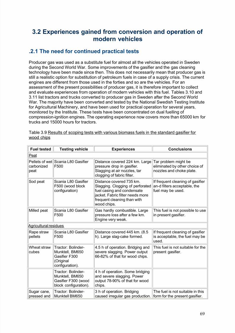
8/6/2019 Gasifier Design
http://slidepdf.com/reader/full/gasifier-design 75/139
3.2 Experiences gained from conversion and operation of modern vehicles
.2.1 The need for continued practical tests
Producer gas was used as a substitute fuel for almost all the vehicles operated in Swedenduring the Second World War. Some improvements of the gasifier and the gas cleaningtechnology have been made since then. This does not necessarily mean that producer gas isstill a realistic option for substitution of petroleum fuels in case of a supply crisis. The currentengines are different from those used in the forties and so are the vehicles. For anassessment of the present possibilities of producer gas, it is therefore important to collectand evaluate experiences from operation of modern vehicles with this fuel. Tables 3.10 and3.11 list tractors and trucks converted to producer gas in Sweden after the Second WorldWar. The majority have been converted and tested by the National Swedish Testing Institutefor Agricultural Machinery, and have been used for practical operation for several years,monitored by the Institute. These tests have been concentrated on dual fuelling of
compression-ignition engines. The operating experience now covers more than 65000 km for trucks and 15000 hours for tractors.
Table 3.9 Results of scoping tests with various biomass fuels in the standard gasifier for wood chips
Fuel tested Testing vehicle Experiences Conclusions
Peat
Pellets of wetcarbonizedpeat
Scania L80 Gasifier F500
Distance covered 224 km. Largepressure drop in gasifier.Slagging at air nozzles, tar
clogging of fabric filter.
Tar problem might beeliminated by other choice of nozzles and choke plate.
Sod peat Scania L80 Gasifier F500 (wood blockconfiguration)
Distance covered 735 km.Slagging. Clogging of perforatedfuel casing and condensate jacket. Fabric filter needs morefrequent cleaning than withwood chips.
If frequent cleaning of gasifier an-d filters acceptable, thefuel may be used.
Milled peat Scania L80 Gasifier F500
Gas hardly combustible. Largepressure loss after a few km.Engine very weak.
This fuel is not possible to usein present gasifier.
Agricultural residues
Rape strawpellets Scania L80 Gasifier F500 Distance covered 445 km. (8.5h). Large slag-cake formed. If frequent cleaning of gasifier is acceptable, the fuel may beused.
Wheat strawcubes
Tractor: Bolinder-Munktell, BM650Gasifier F300(Originalconfiguration).
4.5 h of operation. Bridging andsevere slagging. Power output66-82% of that for wood chips.
This fuel is not suitable for thepresent gasifier.
Tractor: Bolinder-Munktell, BM650Gasifier F300 (woodblock configuration).
4 h of operation. Some bridgingand severe slagging. Power output 78-90% of that for woodchips.
Sugar cane,pressed and Tractor: Bolinder-Munktell BM650 3 h of operation. Bridgingcaused irregular gas production. The fuel is not suitable in thisform for the present gasifier.
69
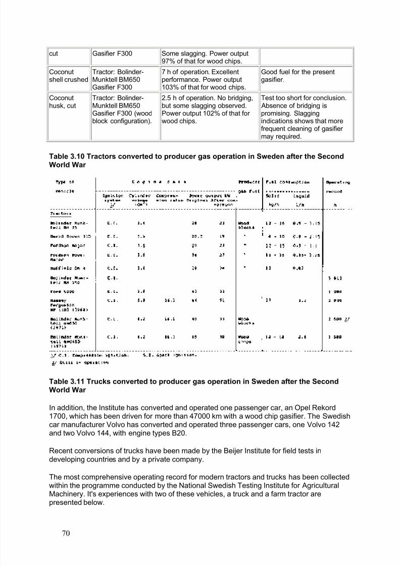
8/6/2019 Gasifier Design
http://slidepdf.com/reader/full/gasifier-design 76/139
cut Gasifier F300 Some slagging. Power output97% of that for wood chips.
Coconutshell crushed
Tractor: Bolinder-Munktell BM650Gasifier F300
7 h of operation. Excellentperformance. Power output103% of that for wood chips.
Good fuel for the presentgasifier.
Coconuthusk, cut Tractor: Bolinder-Munktell BM650Gasifier F300 (woodblock configuration).
2.5 h of operation. No bridging,but some slagging observed.Power output 102% of that for wood chips.
Test too short for conclusion. Absence of bridging ispromising. Slaggingindications shows that morefrequent cleaning of gasifier may required.
Table 3.10 Tractors converted to producer gas operation in Sweden after the SecondWorld War
Table 3.11 Trucks converted to producer gas operation in Sweden after the SecondWorld War
In addition, the Institute has converted and operated one passenger car, an Opel Rekord1700, which has been driven for more than 47000 km with a wood chip gasifier. The Swedishcar manufacturer Volvo has converted and operated three passenger cars, one Volvo 142and two Volvo 144, with engine types B20.
Recent conversions of trucks have been made by the Beijer Institute for field tests indeveloping countries and by a private company.
The most comprehensive operating record for modern tractors and trucks has been collectedwithin the programme conducted by the National Swedish Testing Institute for Agricultural
Machinery. It's experiences with two of these vehicles, a truck and a farm tractor arepresented below.
70
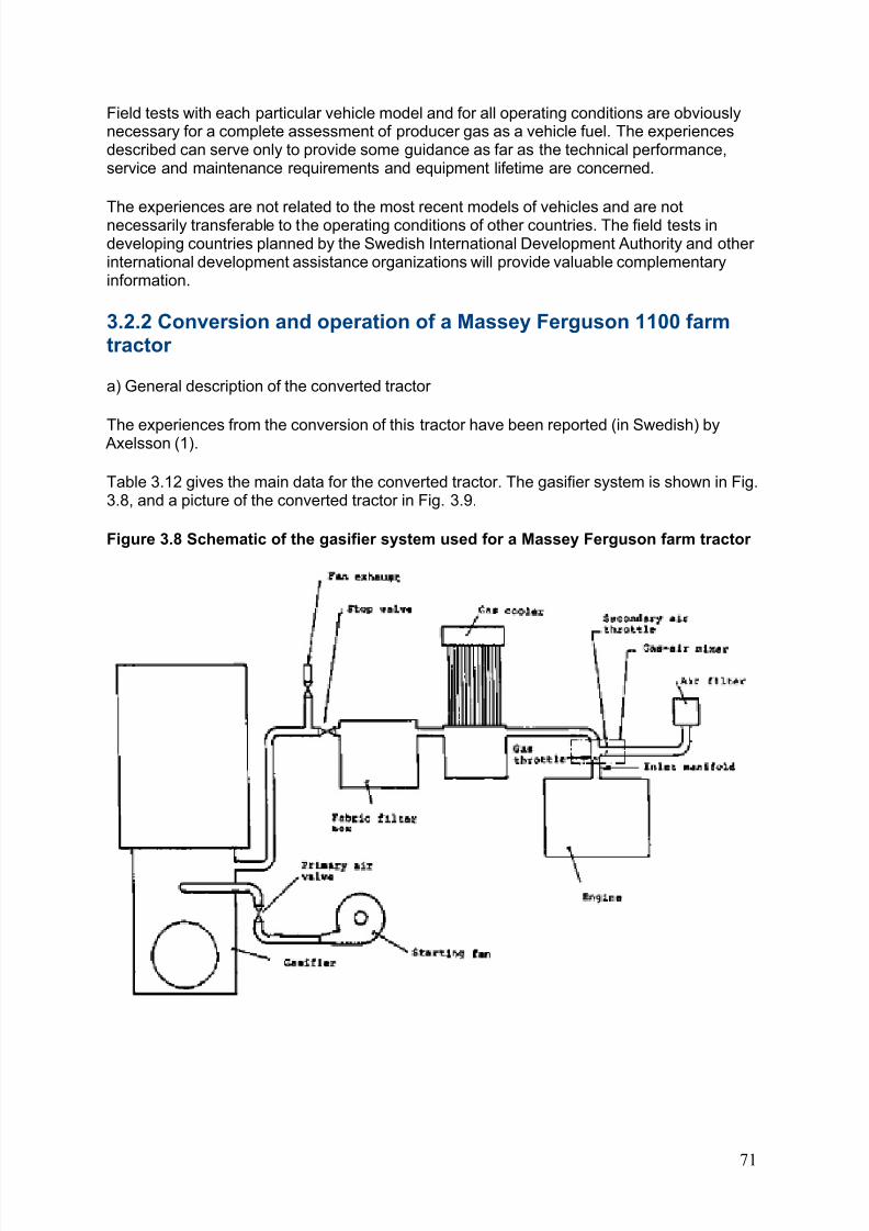
8/6/2019 Gasifier Design
http://slidepdf.com/reader/full/gasifier-design 77/139
Field tests with each particular vehicle model and for all operating conditions are obviouslynecessary for a complete assessment of producer gas as a vehicle fuel. The experiencesdescribed can serve only to provide some guidance as far as the technical performance,service and maintenance requirements and equipment lifetime are concerned.
The experiences are not related to the most recent models of vehicles and are notnecessarily transferable to the operating conditions of other countries. The field tests indeveloping countries planned by the Swedish International Development Authority and other international development assistance organizations will provide valuable complementaryinformation.
3.2.2 Conversion and operation of a Massey Ferguson 1100 farmtractor
a) General description of the converted tractor
The experiences from the conversion of this tractor have been reported (in Swedish) by Axelsson (1).
Table 3.12 gives the main data for the converted tractor. The gasifier system is shown in Fig.3.8, and a picture of the converted tractor in Fig. 3.9.
Figure 3.8 Schematic of the gasifier system used for a Massey Ferguson farm tractor
71
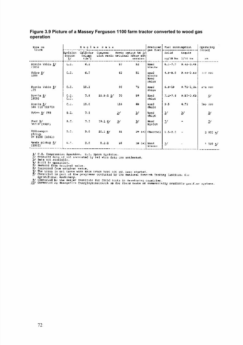
8/6/2019 Gasifier Design
http://slidepdf.com/reader/full/gasifier-design 78/139
Figure 3.9 Picture of a Massey Ferguson 1100 farm tractor converted to wood gasoperation
72
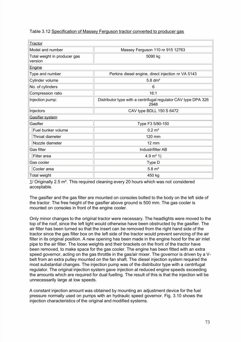
8/6/2019 Gasifier Design
http://slidepdf.com/reader/full/gasifier-design 79/139
Table 3.12 Specification of Massey Ferguson tractor converted to producer gas
Tractor
Model and number Massey Ferguson 110 nr 915 12763
Total weight in producer gas
version
5090 kg
Engine
Type and number Perkins diesel engine, direct injection nr VA 5143
Cylinder volume 5.8 dm³
No. of cylinders 6
Compression ratio 16:1
Injection pump: Distributor type with a centrifugal regulator CAV type DPA 3262948
Injectors CAV type BDLL 150 S 6472
Gasifier system
Gasifier Type F3 5/80-150
Fuel bunker volume 0.2 m³
Throat diameter 120 mm
Nozzle diameter 12 mm
Gas filter Industrifilter AB
Filter area 4.9 m² 1)
Gas cooler Type D
Cooler area 5.8 m²
Total weight 450 kg
1/ Originally 2.5 m². This required cleaning every 20 hours which was not consideredacceptable.
The gasifier and the gas filter are mounted on consoles bolted to the body on the left side of the tractor. The free height of the gasifier above ground is 500 mm. The gas cooler ismounted on consoles in front of the engine cooler.
Only minor changes to the original tractor were necessary. The headlights were moved to thetop of the roof, since the left light would otherwise have been obstructed by the gasifier. Theair filter has been turned so that the insert can be removed from the right hand side of thetractor since the gas filter box on the left side of the tractor would prevent servicing of the air
filter in its original position. A new opening has been made in the engine hood for the air inletpipe to the air filter. The loose weights and their brackets on the front of the tractor havebeen removed, to make space for the gas cooler. The engine has been fitted with an extraspeed governor, acting on the gas throttle in the gas/air mixer. The governor is driven by a V-belt from an extra pulley mounted on the fan shaft. The diesel injection system required themost substantial changes. The injection pump was of the distributor type with a centrifugalregulator. The original injection system gave injection at reduced engine speeds exceedingthe amounts which are required for dual fuelling. The result of this is that the injection will beunnecessarily large at low speeds.
A constant injection amount was obtained by mounting an adjustment device for the fuelpressure normally used on pumps with an hydraulic speed governor. Fig. 3.10 shows the
injection characteristics of the original and modified systems.
73
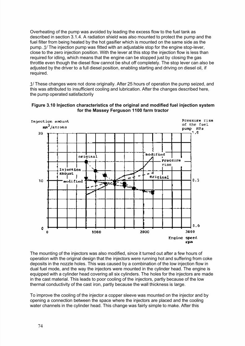
8/6/2019 Gasifier Design
http://slidepdf.com/reader/full/gasifier-design 80/139
Overheating of the pump was avoided by leading the excess flow to the fuel tank asdescribed in section 3.1.4. A radiation shield was also mounted to protect the pump and thefuel filter from being heated by the hot gasifier which is mounted on the same side as thepump. 1/ The injection pump was fitted with an adjustable stop for the engine stop-lever,close to the zero injection position. With the lever at this stop the injection flow is less thanrequired for idling, which means that the engine can be stopped just by closing the gasthrottle even though the diesel flow cannot be shut off completely. The stop lever can also beadjusted by the driver to a full diesel position, enabling starting and driving on diesel oil, if required.
1/ These changes were not done originally. After 25 hours of operation the pump seized, andthis was attributed to insufficient cooling and lubrication. After the changes described here,the pump operated satisfactorily
Figure 3.10 Injection characteristics of the original and modified fuel injection systemfor the Massey Ferguson 1100 farm tractor
The mounting of the injectors was also modified, since it turned out after a few hours of operation with the original design that the injectors were running hot and suffering from cokedeposits in the nozzle holes. This was caused by a combination of the low injection flow indual fuel mode, and the way the injectors were mounted in the cylinder head. The engine isequipped with a cylinder head covering all six cylinders. The holes for the injectors are madein the cast material. This leads to poor cooling of the injectors, partly because of the lowthermal conductivity of the cast iron, partly because the wall thickness is large.
To improve the cooling of the injector a copper sleeve was mounted on the injector and byopening a connection between the space where the injectors are placed and the coolingwater channels in the cylinder head. This change was fairly simple to make. After this
74
8/6/2019 Gasifier Design
http://slidepdf.com/reader/full/gasifier-design 81/139
modification, it was necessary to drain the cooling water from the engine before removal of the injectors.
The total height of the gasifier above ground is 222 cm. The eye level of the driver is 225 -240 cm, depending on how the seat is adjusted. The field of vision in the forward leftdirection is partly obstructed by the gasifier and the filter box. To the right and backwards, thefield of vision is not affected.
b) Laboratory performance tests
Laboratory tests were carried out to establish the performance of the gasifier system and theconverted engine.
A summary of the test results is given in Table 3.13 and Fig. 3.11. The maximum power indual fuel mode was found to be 51 kW at about 2170 rpm (injection timing 30° before TDC).This is 79% of the maximum power for straight diesel operation at recommended injectiontiming (22° before TDC) and 76% of the diesel power at the same injection timing as for dual
fuelling. As can be seen in Table 3.13, the diesel oil substitution was found to be 80-85% andthe efficiency of the gasifier system about 70%. Solid residue in the ash pit was found to beup to 3.5% of the fuel consumption. This would account for a loss of about 5% at full power.
Tests were also made with injectors other than the original four hole type. Pintle typeinjectors in the original cylinder head showed no tendency for coking - the injectors are self cleaning - but the maximum power in dual fuel operation was 19 percent lower than for thefour hole type. Straight diesel operation with this injector was not considered possible, sincevery smoky exhaust gases were already obtained at low powers. Two-hole injectors gave thesame power output in dual fuel mode as the four-hole injectors for engine speeds up to 1900rpm and slightly less above. For straight diesel operation, the power output was generallylower than for four-hold injectors over the whole speed range.
75
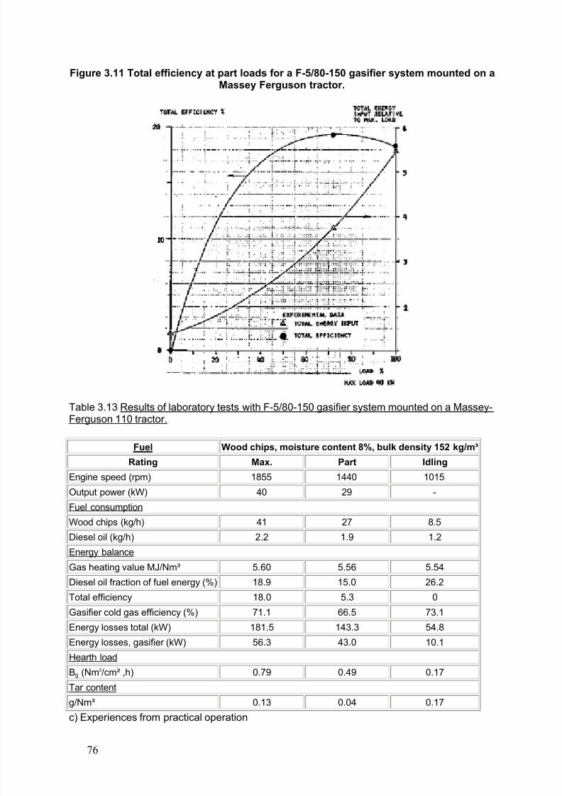
8/6/2019 Gasifier Design
http://slidepdf.com/reader/full/gasifier-design 82/139
Figure 3.11 Total efficiency at part loads for a F-5/80-150 gasifier system mounted on aMassey Ferguson tractor.
Table 3.13 Results of laboratory tests with F-5/80-150 gasifier system mounted on a Massey-
Ferguson 110 tractor.
Fuel Wood chips, moisture content 8%, bulk density 152 kg/m³
Rating Max. Part Idling
Engine speed (rpm) 1855 1440 1015
Output power (kW) 40 29 -
Fuel consumption
Wood chips (kg/h) 41 27 8.5
Diesel oil (kg/h) 2.2 1.9 1.2
Energy balance
Gas heating value MJ/Nm³ 5.60 5.56 5.54
Diesel oil fraction of fuel energy (%) 18.9 15.0 26.2
Total efficiency 18.0 5.3 0
Gasifier cold gas efficiency (%) 71.1 66.5 73.1
Energy losses total (kW) 181.5 143.3 54.8
Energy losses, gasifier (kW) 56.3 43.0 10.1
Hearth load
Bg (Nm3/cm² ,h) 0.79 0.49 0.17
Tar content
g/Nm³ 0.13 0.04 0.17
c) Experiences from practical operation
76
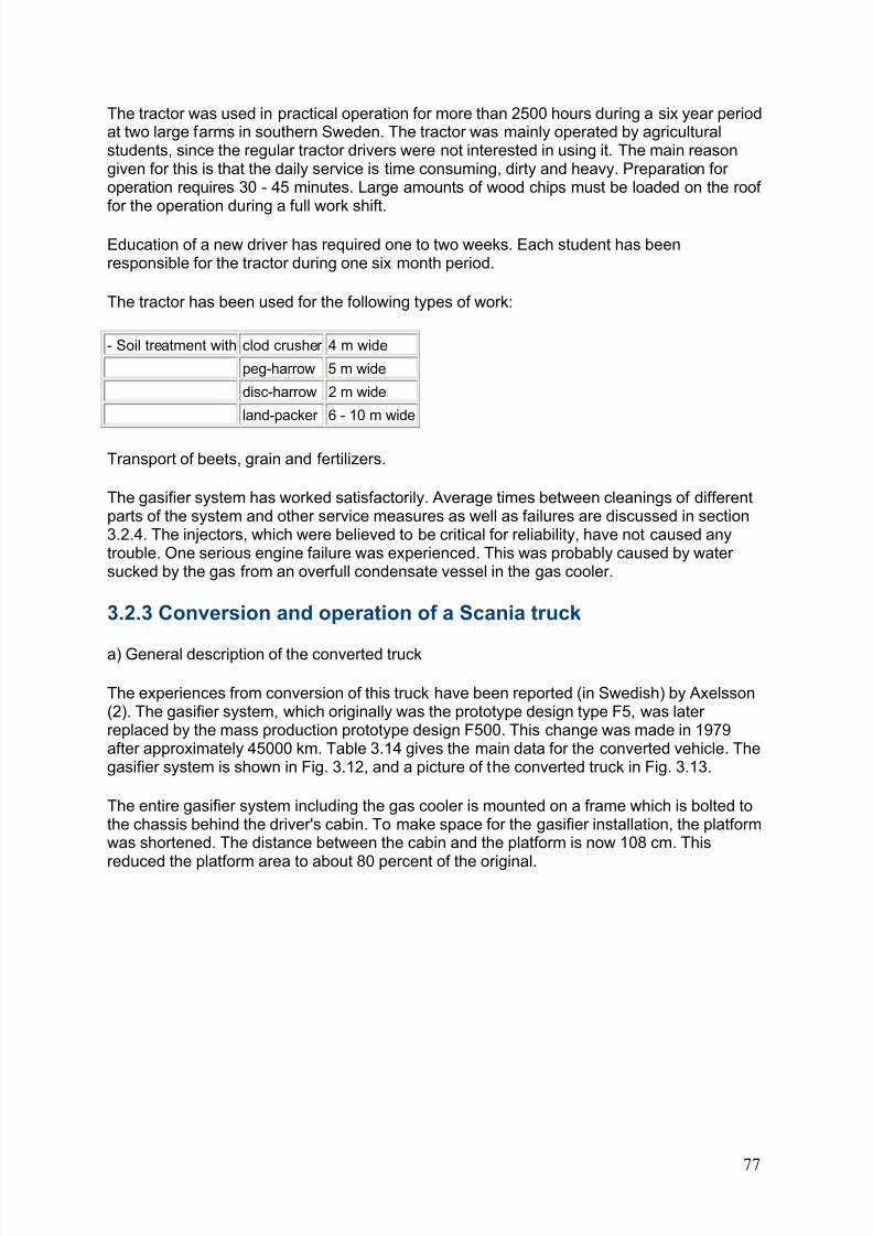
8/6/2019 Gasifier Design
http://slidepdf.com/reader/full/gasifier-design 83/139
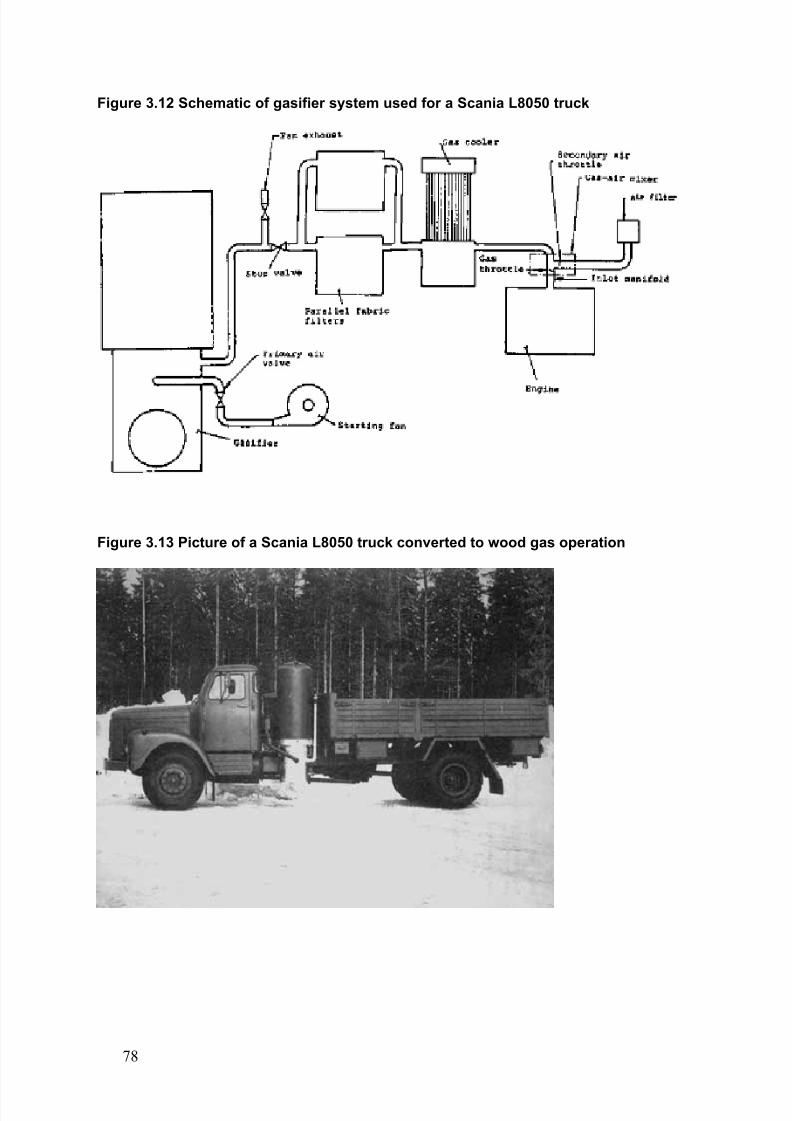
8/6/2019 Gasifier Design
http://slidepdf.com/reader/full/gasifier-design 84/139
Figure 3.12 Schematic of gasifier system used for a Scania L8050 truck
Figure 3.13 Picture of a Scania L8050 truck converted to wood gas operation
78
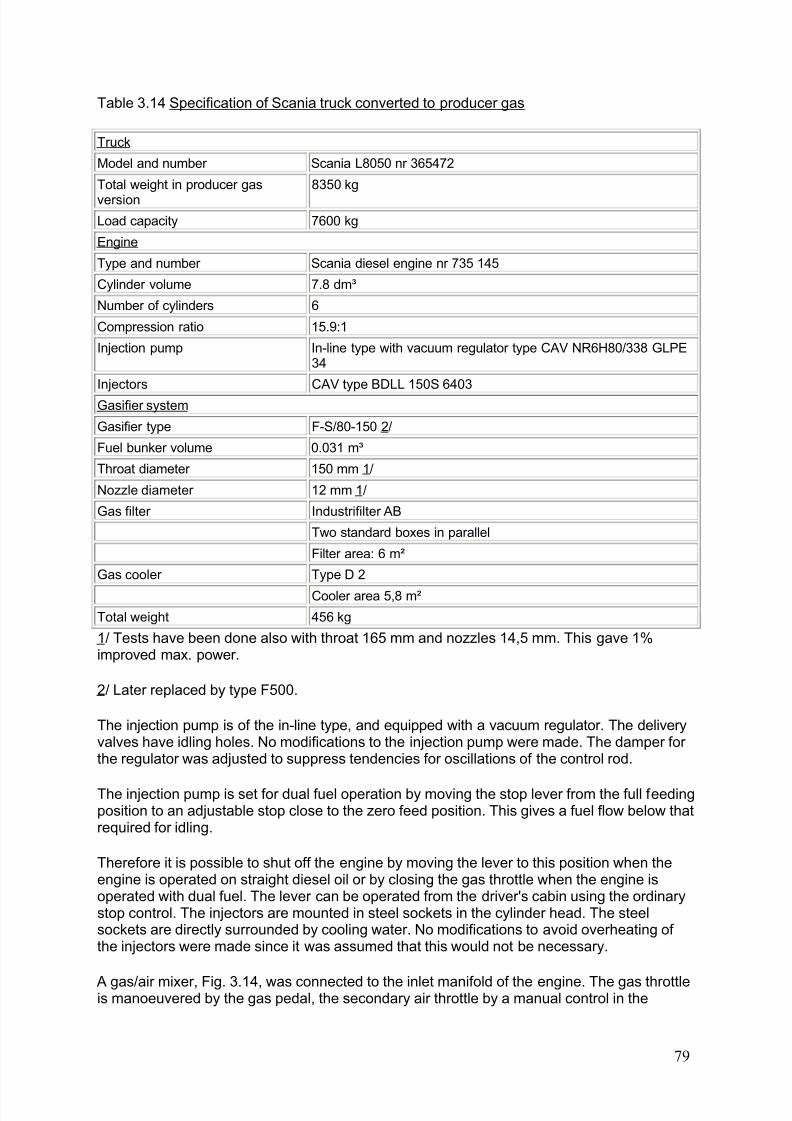
8/6/2019 Gasifier Design
http://slidepdf.com/reader/full/gasifier-design 85/139
Table 3.14 Specification of Scania truck converted to producer gas
Truck
Model and number Scania L8050 nr 365472
Total weight in producer gas
version
8350 kg
Load capacity 7600 kg
Engine
Type and number Scania diesel engine nr 735 145
Cylinder volume 7.8 dm³
Number of cylinders 6
Compression ratio 15.9:1
Injection pump In-line type with vacuum regulator type CAV NR6H80/338 GLPE34
Injectors CAV type BDLL 150S 6403
Gasifier system
Gasifier type F-S/80-150 2/
Fuel bunker volume 0.031 m³
Throat diameter 150 mm 1/
Nozzle diameter 12 mm 1/
Gas filter Industrifilter AB
Two standard boxes in parallel
Filter area: 6 m²
Gas cooler Type D 2
Cooler area 5,8 m²
Total weight 456 kg
1/ Tests have been done also with throat 165 mm and nozzles 14,5 mm. This gave 1%improved max. power.
2/ Later replaced by type F500.
The injection pump is of the in-line type, and equipped with a vacuum regulator. The deliveryvalves have idling holes. No modifications to the injection pump were made. The damper for the regulator was adjusted to suppress tendencies for oscillations of the control rod.
The injection pump is set for dual fuel operation by moving the stop lever from the full feedingposition to an adjustable stop close to the zero feed position. This gives a fuel flow below thatrequired for idling.
Therefore it is possible to shut off the engine by moving the lever to this position when theengine is operated on straight diesel oil or by closing the gas throttle when the engine isoperated with dual fuel. The lever can be operated from the driver's cabin using the ordinarystop control. The injectors are mounted in steel sockets in the cylinder head. The steelsockets are directly surrounded by cooling water. No modifications to avoid overheating of the injectors were made since it was assumed that this would not be necessary.
A gas/air mixer, Fig. 3.14, was connected to the inlet manifold of the engine. The gas throttleis manoeuvered by the gas pedal, the secondary air throttle by a manual control in the
79
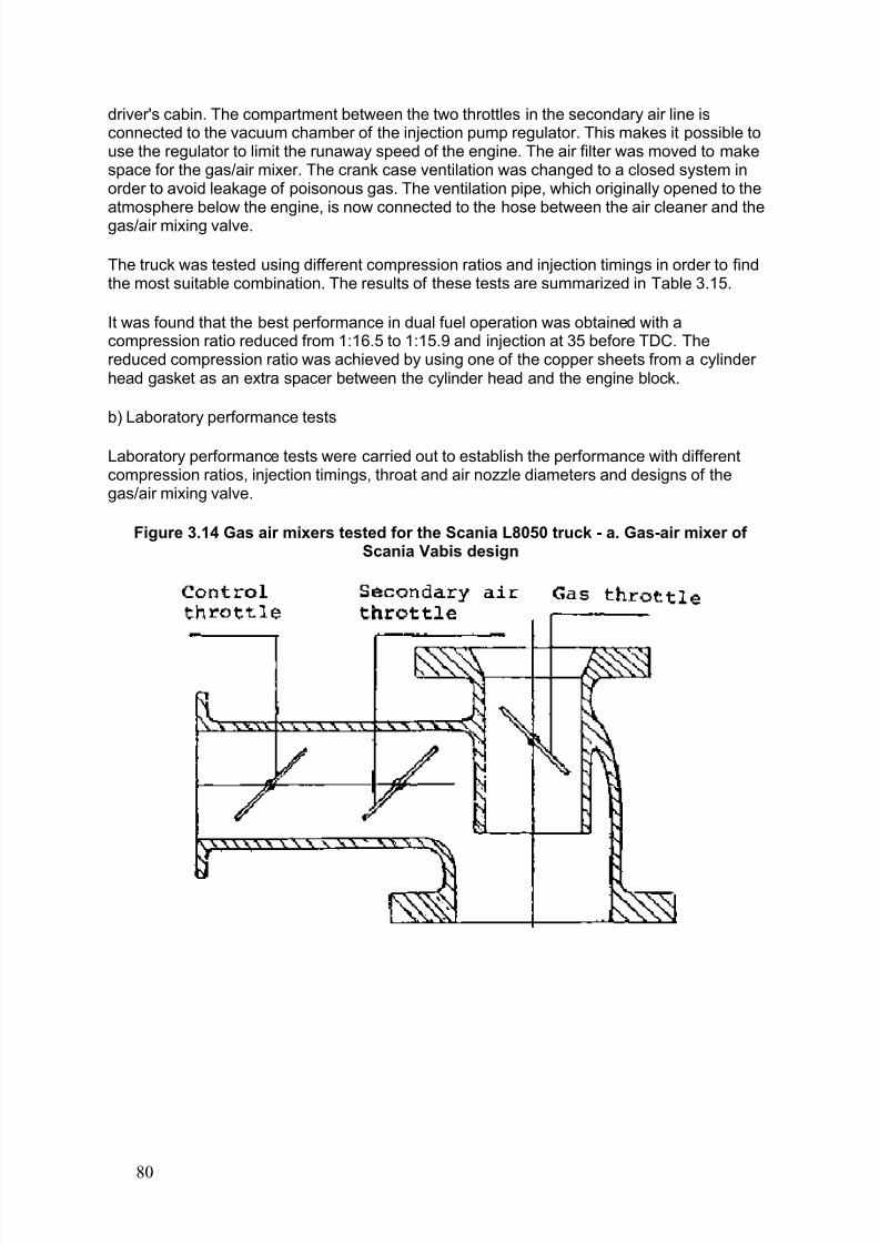
8/6/2019 Gasifier Design
http://slidepdf.com/reader/full/gasifier-design 86/139
driver's cabin. The compartment between the two throttles in the secondary air line isconnected to the vacuum chamber of the injection pump regulator. This makes it possible touse the regulator to limit the runaway speed of the engine. The air filter was moved to makespace for the gas/air mixer. The crank case ventilation was changed to a closed system inorder to avoid leakage of poisonous gas. The ventilation pipe, which originally opened to theatmosphere below the engine, is now connected to the hose between the air cleaner and thegas/air mixing valve.
The truck was tested using different compression ratios and injection timings in order to findthe most suitable combination. The results of these tests are summarized in Table 3.15.
It was found that the best performance in dual fuel operation was obtained with acompression ratio reduced from 1:16.5 to 1:15.9 and injection at 35 before TDC. Thereduced compression ratio was achieved by using one of the copper sheets from a cylinder head gasket as an extra spacer between the cylinder head and the engine block.
b) Laboratory performance tests
Laboratory performance tests were carried out to establish the performance with differentcompression ratios, injection timings, throat and air nozzle diameters and designs of thegas/air mixing valve.
Figure 3.14 Gas air mixers tested for the Scania L8050 truck - a. Gas-air mixer of Scania Vabis design
80
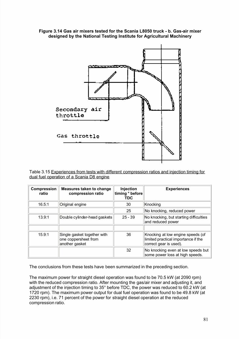
8/6/2019 Gasifier Design
http://slidepdf.com/reader/full/gasifier-design 87/139
Figure 3.14 Gas air mixers tested for the Scania L8050 truck - b. Gas-air mixer designed by the National Testing Institute for Agricultural Machinery
Table 3.15 Experiences from tests with different compression ratios and injection timing for
dual fuel operation of a Scania D8 engine
Compressionratio
Measures taken to changecompression ratio
Injectiontiming ° before
TDC
Experiences
16.5:1 Original engine 30 Knocking
25 No knocking, reduced power
13.9:1 Double cylinder-head gaskets 25 - 39 No knocking, but starting difficultiesand reduced power
15.9:1 Single gasket together withone coppersheet fromanother gasket
36 Knocking at low engine speeds (of limited practical importance if thecorrect gear is used).
32 No knocking even at low speeds butsome power loss at high speeds.
The conclusions from these tests have been summarized in the preceding section.
The maximum power for straight diesel operation was found to be 70.5 kW (at 2090 rpm)with the reduced compression ratio. After mounting the gas/air mixer and adjusting it, andadjustment of the injection timing to 35° before TDC, the power was reduced to 60.2 kW (at1720 rpm). The maximum power output for dual fuel operation was found to be 49.8 kW (at
2230 rpm), i.e. 71 percent of the power for straight diesel operation at the reducedcompression ratio.
81
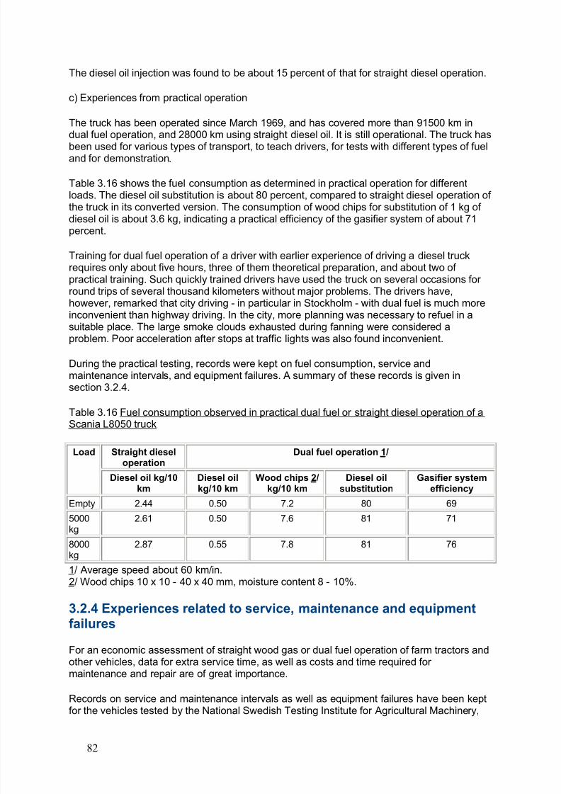
8/6/2019 Gasifier Design
http://slidepdf.com/reader/full/gasifier-design 88/139
The diesel oil injection was found to be about 15 percent of that for straight diesel operation.
c) Experiences from practical operation
The truck has been operated since March 1969, and has covered more than 91500 km in
dual fuel operation, and 28000 km using straight diesel oil. It is still operational. The truck hasbeen used for various types of transport, to teach drivers, for tests with different types of fueland for demonstration.
Table 3.16 shows the fuel consumption as determined in practical operation for differentloads. The diesel oil substitution is about 80 percent, compared to straight diesel operation of the truck in its converted version. The consumption of wood chips for substitution of 1 kg of diesel oil is about 3.6 kg, indicating a practical efficiency of the gasifier system of about 71percent.
Training for dual fuel operation of a driver with earlier experience of driving a diesel truckrequires only about five hours, three of them theoretical preparation, and about two of
practical training. Such quickly trained drivers have used the truck on several occasions for round trips of several thousand kilometers without major problems. The drivers have,however, remarked that city driving - in particular in Stockholm - with dual fuel is much moreinconvenient than highway driving. In the city, more planning was necessary to refuel in asuitable place. The large smoke clouds exhausted during fanning were considered aproblem. Poor acceleration after stops at traffic lights was also found inconvenient.
During the practical testing, records were kept on fuel consumption, service andmaintenance intervals, and equipment failures. A summary of these records is given insection 3.2.4.
Table 3.16 Fuel consumption observed in practical dual fuel or straight diesel operation of aScania L8050 truck
Straight dieseloperation
Dual fuel operation 1/ Load
Diesel oil kg/10km
Diesel oilkg/10 km
Wood chips 2/kg/10 km
Diesel oilsubstitution
Gasifier systemefficiency
Empty 2.44 0.50 7.2 80 69
5000kg
2.61 0.50 7.6 81 71
8000
kg
2.87 0.55 7.8 81 76
1/ Average speed about 60 km/in.2/ Wood chips 10 x 10 - 40 x 40 mm, moisture content 8 - 10%.
3.2.4 Experiences related to service, maintenance and equipmentfailures
For an economic assessment of straight wood gas or dual fuel operation of farm tractors andother vehicles, data for extra service time, as well as costs and time required for maintenance and repair are of great importance.
Records on service and maintenance intervals as well as equipment failures have been keptfor the vehicles tested by the National Swedish Testing Institute for Agricultural Machinery,
82
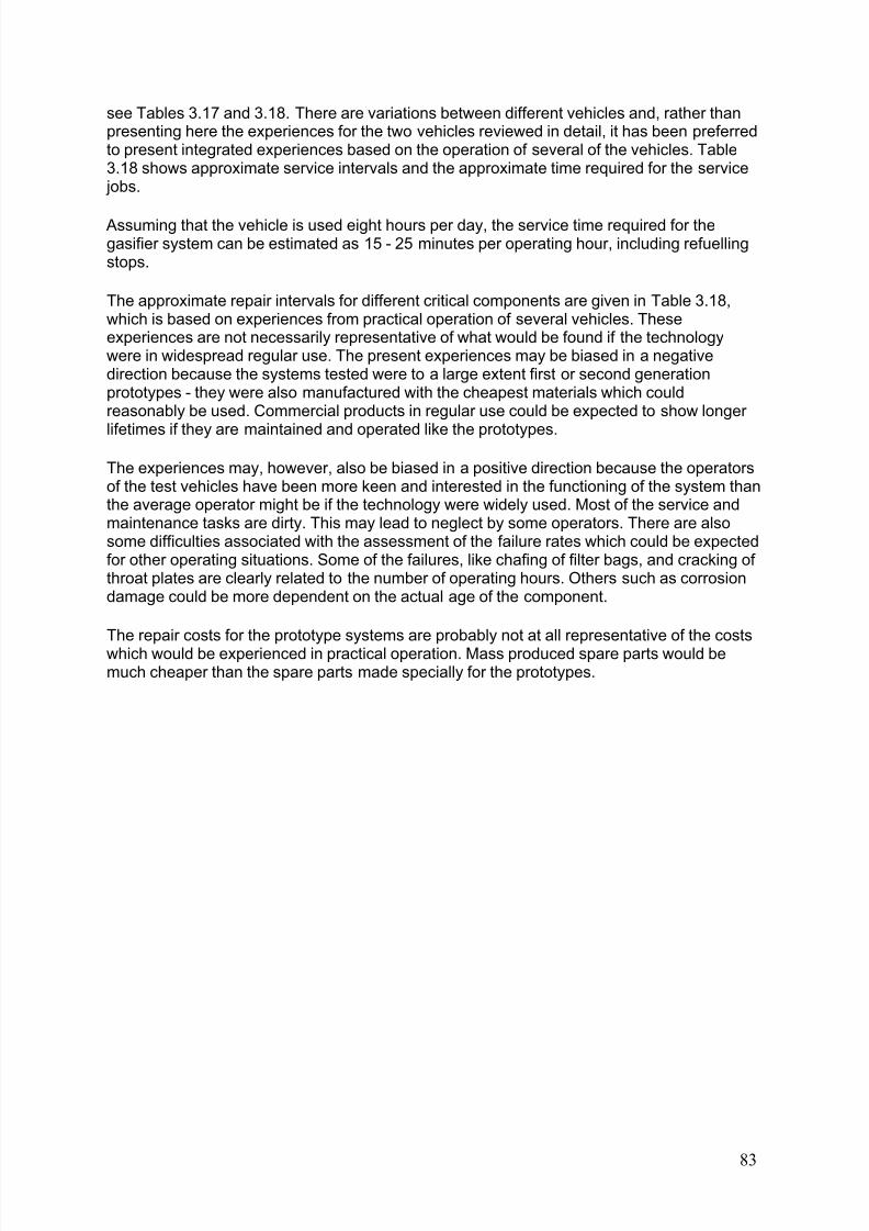
8/6/2019 Gasifier Design
http://slidepdf.com/reader/full/gasifier-design 89/139
see Tables 3.17 and 3.18. There are variations between different vehicles and, rather thanpresenting here the experiences for the two vehicles reviewed in detail, it has been preferredto present integrated experiences based on the operation of several of the vehicles. Table3.18 shows approximate service intervals and the approximate time required for the service jobs.
Assuming that the vehicle is used eight hours per day, the service time required for thegasifier system can be estimated as 15 - 25 minutes per operating hour, including refuellingstops.
The approximate repair intervals for different critical components are given in Table 3.18,which is based on experiences from practical operation of several vehicles. Theseexperiences are not necessarily representative of what would be found if the technologywere in widespread regular use. The present experiences may be biased in a negativedirection because the systems tested were to a large extent first or second generationprototypes - they were also manufactured with the cheapest materials which couldreasonably be used. Commercial products in regular use could be expected to show longer
lifetimes if they are maintained and operated like the prototypes.
The experiences may, however, also be biased in a positive direction because the operatorsof the test vehicles have been more keen and interested in the functioning of the system thanthe average operator might be if the technology were widely used. Most of the service andmaintenance tasks are dirty. This may lead to neglect by some operators. There are alsosome difficulties associated with the assessment of the failure rates which could be expectedfor other operating situations. Some of the failures, like chafing of filter bags, and cracking of throat plates are clearly related to the number of operating hours. Others such as corrosiondamage could be more dependent on the actual age of the component.
The repair costs for the prototype systems are probably not at all representative of the costswhich would be experienced in practical operation. Mass produced spare parts would bemuch cheaper than the spare parts made specially for the prototypes.
83
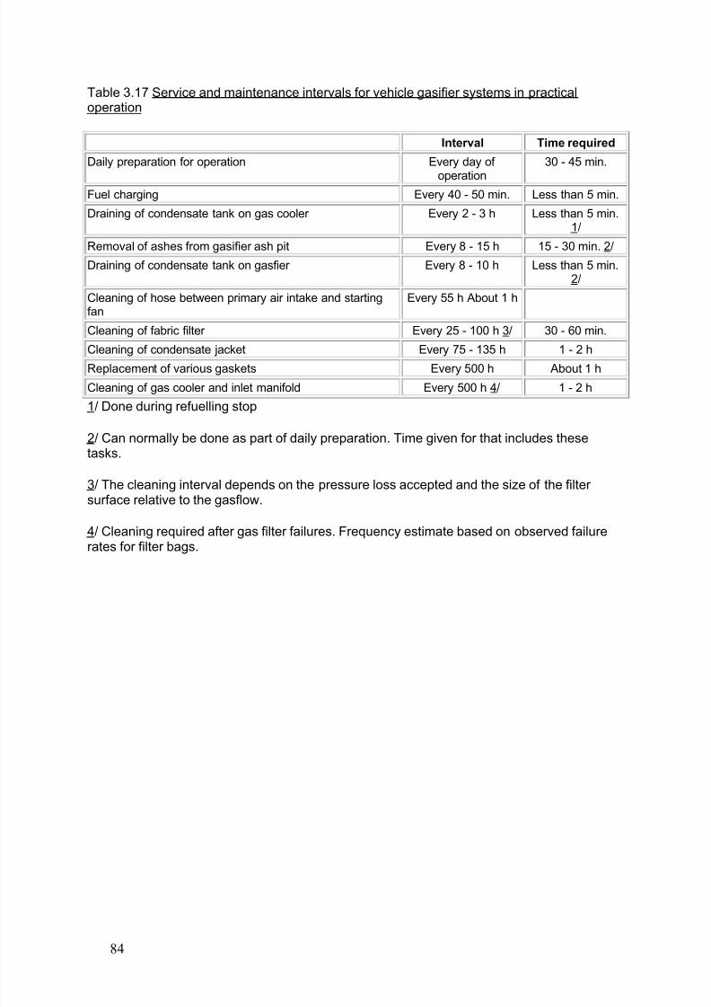
8/6/2019 Gasifier Design
http://slidepdf.com/reader/full/gasifier-design 90/139
Table 3.17 Service and maintenance intervals for vehicle gasifier systems in practicaloperation
Interval Time required
Daily preparation for operation Every day of
operation
30 - 45 min.
Fuel charging Every 40 - 50 min. Less than 5 min.
Draining of condensate tank on gas cooler Every 2 - 3 h Less than 5 min.1/
Removal of ashes from gasifier ash pit Every 8 - 15 h 15 - 30 min. 2/
Draining of condensate tank on gasfier Every 8 - 10 h Less than 5 min.2/
Cleaning of hose between primary air intake and startingfan
Every 55 h About 1 h
Cleaning of fabric filter Every 25 - 100 h 3/ 30 - 60 min.
Cleaning of condensate jacket Every 75 - 135 h 1 - 2 hReplacement of various gaskets Every 500 h About 1 h
Cleaning of gas cooler and inlet manifold Every 500 h 4/ 1 - 2 h
1/ Done during refuelling stop
2/ Can normally be done as part of daily preparation. Time given for that includes thesetasks.
3/ The cleaning interval depends on the pressure loss accepted and the size of the filter surface relative to the gasflow.
4/ Cleaning required after gas filter failures. Frequency estimate based on observed failurerates for filter bags.
84
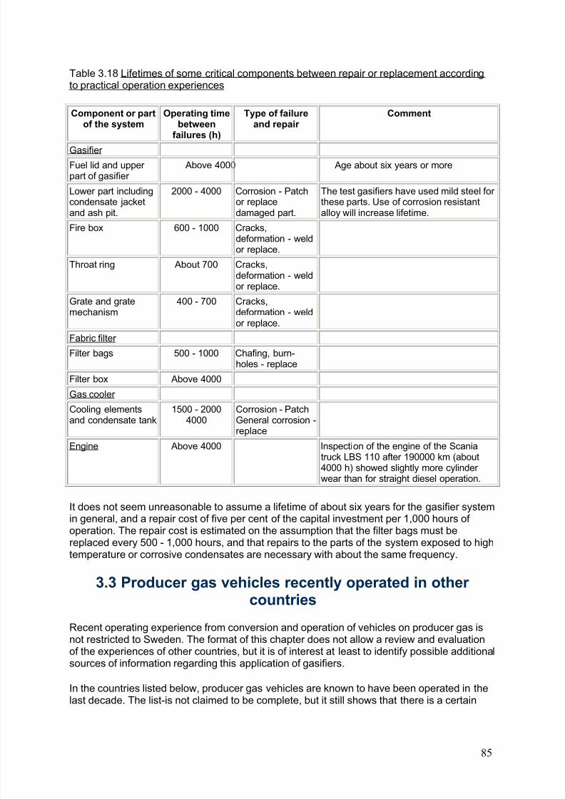
8/6/2019 Gasifier Design
http://slidepdf.com/reader/full/gasifier-design 91/139
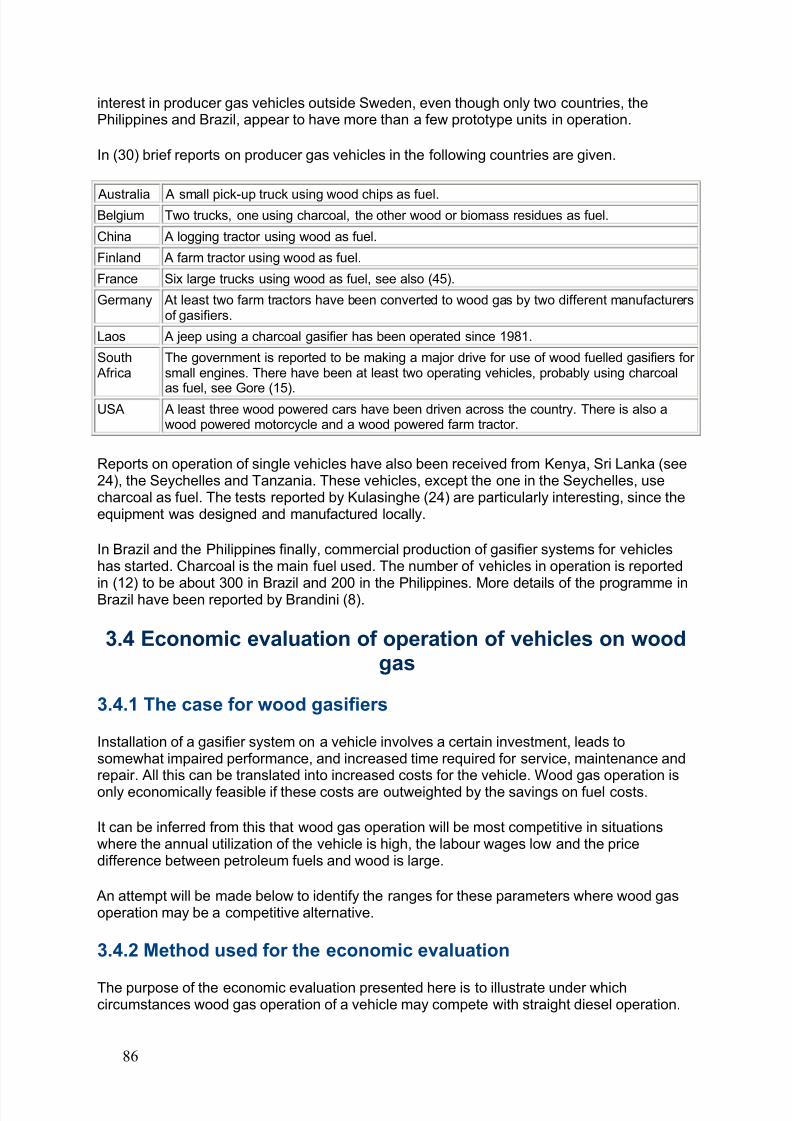
8/6/2019 Gasifier Design
http://slidepdf.com/reader/full/gasifier-design 92/139
interest in producer gas vehicles outside Sweden, even though only two countries, thePhilippines and Brazil, appear to have more than a few prototype units in operation.
In (30) brief reports on producer gas vehicles in the following countries are given.
Australia A small pick-up truck using wood chips as fuel.Belgium Two trucks, one using charcoal, the other wood or biomass residues as fuel.
China A logging tractor using wood as fuel.
Finland A farm tractor using wood as fuel.
France Six large trucks using wood as fuel, see also (45).
Germany At least two farm tractors have been converted to wood gas by two different manufacturersof gasifiers.
Laos A jeep using a charcoal gasifier has been operated since 1981.
South Africa
The government is reported to be making a major drive for use of wood fuelled gasifiers for small engines. There have been at least two operating vehicles, probably using charcoal
as fuel, see Gore (15).USA A least three wood powered cars have been driven across the country. There is also a
wood powered motorcycle and a wood powered farm tractor.
Reports on operation of single vehicles have also been received from Kenya, Sri Lanka (see24), the Seychelles and Tanzania. These vehicles, except the one in the Seychelles, usecharcoal as fuel. The tests reported by Kulasinghe (24) are particularly interesting, since theequipment was designed and manufactured locally.
In Brazil and the Philippines finally, commercial production of gasifier systems for vehicleshas started. Charcoal is the main fuel used. The number of vehicles in operation is reported
in (12) to be about 300 in Brazil and 200 in the Philippines. More details of the programme inBrazil have been reported by Brandini (8).
3.4 Economic evaluation of operation of vehicles on woodgas
3.4.1 The case for wood gasifiers
Installation of a gasifier system on a vehicle involves a certain investment, leads tosomewhat impaired performance, and increased time required for service, maintenance andrepair. All this can be translated into increased costs for the vehicle. Wood gas operation isonly economically feasible if these costs are outweighted by the savings on fuel costs.
It can be inferred from this that wood gas operation will be most competitive in situationswhere the annual utilization of the vehicle is high, the labour wages low and the pricedifference between petroleum fuels and wood is large.
An attempt will be made below to identify the ranges for these parameters where wood gasoperation may be a competitive alternative.
3.4.2 Method used for the economic evaluation
The purpose of the economic evaluation presented here is to illustrate under whichcircumstances wood gas operation of a vehicle may compete with straight diesel operation.
86
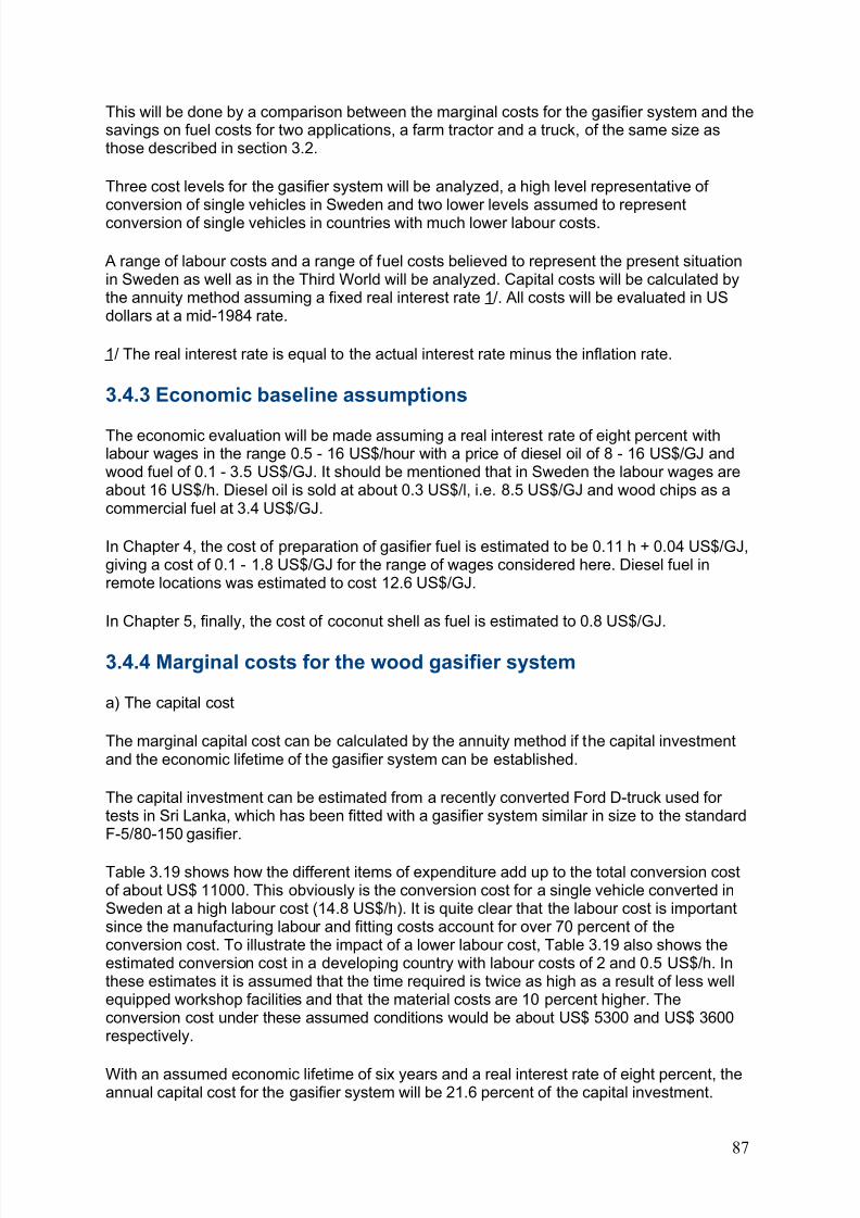
8/6/2019 Gasifier Design
http://slidepdf.com/reader/full/gasifier-design 93/139
This will be done by a comparison between the marginal costs for the gasifier system and thesavings on fuel costs for two applications, a farm tractor and a truck, of the same size asthose described in section 3.2.
Three cost levels for the gasifier system will be analyzed, a high level representative of conversion of single vehicles in Sweden and two lower levels assumed to representconversion of single vehicles in countries with much lower labour costs.
A range of labour costs and a range of fuel costs believed to represent the present situationin Sweden as well as in the Third World will be analyzed. Capital costs will be calculated bythe annuity method assuming a fixed real interest rate 1/. All costs will be evaluated in USdollars at a mid-1984 rate.
1/ The real interest rate is equal to the actual interest rate minus the inflation rate.
3.4.3 Economic baseline assumptions
The economic evaluation will be made assuming a real interest rate of eight percent withlabour wages in the range 0.5 - 16 US$/hour with a price of diesel oil of 8 - 16 US$/GJ andwood fuel of 0.1 - 3.5 US$/GJ. It should be mentioned that in Sweden the labour wages areabout 16 US$/h. Diesel oil is sold at about 0.3 US$/l, i.e. 8.5 US$/GJ and wood chips as acommercial fuel at 3.4 US$/GJ.
In Chapter 4, the cost of preparation of gasifier fuel is estimated to be 0.11 h + 0.04 US$/GJ,giving a cost of 0.1 - 1.8 US$/GJ for the range of wages considered here. Diesel fuel inremote locations was estimated to cost 12.6 US$/GJ.
In Chapter 5, finally, the cost of coconut shell as fuel is estimated to 0.8 US$/GJ.
3.4.4 Marginal costs for the wood gasifier system
a) The capital cost
The marginal capital cost can be calculated by the annuity method if the capital investmentand the economic lifetime of the gasifier system can be established.
The capital investment can be estimated from a recently converted Ford D-truck used for tests in Sri Lanka, which has been fitted with a gasifier system similar in size to the standardF-5/80-150 gasifier.
Table 3.19 shows how the different items of expenditure add up to the total conversion costof about US$ 11000. This obviously is the conversion cost for a single vehicle converted inSweden at a high labour cost (14.8 US$/h). It is quite clear that the labour cost is importantsince the manufacturing labour and fitting costs account for over 70 percent of theconversion cost. To illustrate the impact of a lower labour cost, Table 3.19 also shows theestimated conversion cost in a developing country with labour costs of 2 and 0.5 US$/h. Inthese estimates it is assumed that the time required is twice as high as a result of less wellequipped workshop facilities and that the material costs are 10 percent higher. Theconversion cost under these assumed conditions would be about US$ 5300 and US$ 3600respectively.
With an assumed economic lifetime of six years and a real interest rate of eight percent, theannual capital cost for the gasifier system will be 21.6 percent of the capital investment.
87
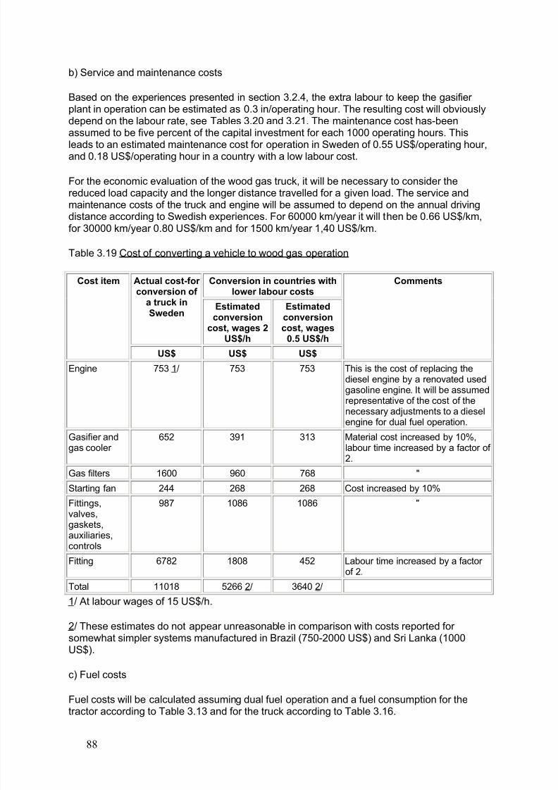
8/6/2019 Gasifier Design
http://slidepdf.com/reader/full/gasifier-design 94/139
b) Service and maintenance costs
Based on the experiences presented in section 3.2.4, the extra labour to keep the gasifier plant in operation can be estimated as 0.3 in/operating hour. The resulting cost will obviouslydepend on the labour rate, see Tables 3.20 and 3.21. The maintenance cost has-beenassumed to be five percent of the capital investment for each 1000 operating hours. Thisleads to an estimated maintenance cost for operation in Sweden of 0.55 US$/operating hour,and 0.18 US$/operating hour in a country with a low labour cost.
For the economic evaluation of the wood gas truck, it will be necessary to consider thereduced load capacity and the longer distance travelled for a given load. The service andmaintenance costs of the truck and engine will be assumed to depend on the annual drivingdistance according to Swedish experiences. For 60000 km/year it will then be 0.66 US$/km,for 30000 km/year 0.80 US$/km and for 1500 km/year 1,40 US$/km.
Table 3.19 Cost of converting a vehicle to wood gas operation
Conversion in countries withlower labour costs
Actual cost-for conversion of
a truck inSweden
Estimatedconversion
cost, wages 2US$/h
Estimatedconversioncost, wages
0.5 US$/h
Cost item
US$ US$ US$
Comments
Engine 753 1/ 753 753 This is the cost of replacing thediesel engine by a renovated usedgasoline engine. It will be assumedrepresentative of the cost of the
necessary adjustments to a dieselengine for dual fuel operation.
Gasifier andgas cooler
652 391 313 Material cost increased by 10%,labour time increased by a factor of 2.
Gas filters 1600 960 768 "
Starting fan 244 268 268 Cost increased by 10%
Fittings,valves,gaskets,auxiliaries,controls
987 1086 1086 "
Fitting 6782 1808 452 Labour time increased by a factor of 2.
Total 11018 5266 2/ 3640 2/
1/ At labour wages of 15 US$/h.
2/ These estimates do not appear unreasonable in comparison with costs reported for somewhat simpler systems manufactured in Brazil (750-2000 US$) and Sri Lanka (1000US$).
c) Fuel costs
Fuel costs will be calculated assuming dual fuel operation and a fuel consumption for thetractor according to Table 3.13 and for the truck according to Table 3.16.
88
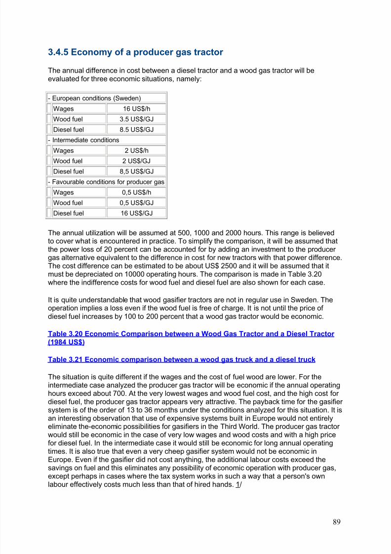
8/6/2019 Gasifier Design
http://slidepdf.com/reader/full/gasifier-design 95/139
3.4.5 Economy of a producer gas tractor
The annual difference in cost between a diesel tractor and a wood gas tractor will beevaluated for three economic situations, namely:
- European conditions (Sweden)Wages 16 US$/h
Wood fuel 3.5 US$/GJ
Diesel fuel 8.5 US$/GJ
- Intermediate conditions
Wages 2 US$/h
Wood fuel 2 US$/GJ
Diesel fuel 8,5 US$/GJ
- Favourable conditions for producer gas
Wages 0,5 US$/hWood fuel 0,5 US$/GJ
Diesel fuel 16 US$/GJ
The annual utilization will be assumed at 500, 1000 and 2000 hours. This range is believedto cover what is encountered in practice. To simplify the comparison, it will be assumed thatthe power loss of 20 percent can be accounted for by adding an investment to the producer gas alternative equivalent to the difference in cost for new tractors with that power difference.The cost difference can be estimated to be about US$ 2500 and it will be assumed that itmust be depreciated on 10000 operating hours. The comparison is made in Table 3.20where the indifference costs for wood fuel and diesel fuel are also shown for each case.
It is quite understandable that wood gasifier tractors are not in regular use in Sweden. Theoperation implies a loss even if the wood fuel is free of charge. It is not until the price of diesel fuel increases by 100 to 200 percent that a wood gas tractor would be economic.
Table 3.20 Economic Comparison between a Wood Gas Tractor and a Diesel Tractor (1984 US$)
Table 3.21 Economic comparison between a wood gas truck and a diesel truck
The situation is quite different if the wages and the cost of fuel wood are lower. For the
intermediate case analyzed the producer gas tractor will be economic if the annual operatinghours exceed about 700. At the very lowest wages and wood fuel cost, and the high cost for diesel fuel, the producer gas tractor appears very attractive. The payback time for the gasifier system is of the order of 13 to 36 months under the conditions analyzed for this situation. It isan interesting observation that use of expensive systems built in Europe would not entirelyeliminate the-economic possibilities for gasifiers in the Third World. The producer gas tractor would still be economic in the case of very low wages and wood costs and with a high pricefor diesel fuel. In the intermediate case it would still be economic for long annual operatingtimes. It is also true that even a very cheep gasifier system would not be economic inEurope. Even if the gasifier did not cost anything, the additional labour costs exceed thesavings on fuel and this eliminates any possibility of economic operation with producer gas,except perhaps in cases where the tax system works in such a way that a person's own
labour effectively costs much less than that of hired hands. 1/
89
8/6/2019 Gasifier Design
http://slidepdf.com/reader/full/gasifier-design 96/139
1/ The situation could be applicable under some circumstances in Sweden.
3.4.6 Economy of a producer gas truck
The difference in annual cost between a diesel truck and a wood gas truck will be evaluated
for the same economic situations as considered for the tractor. The initial cost of the truck isassumed to be US$ 28000, with ten percent added for freight costs to a third world country.
The difference in cost is shown in Table 3.21 for three utilization levels, i.e. 60000, 120000and 240000 tons and kilometers per year.
The average velocity is assumed to be ten percent Less for producer gas operation, mainlybecause of stops for fuel charging. In European conditions the average velocity is assumedto be 60 km/in for the diesel vehicle. In the other cases, where road conditions are lessfavourable, the average velocity is assumed to be 25 km/h.
As can be expected, the results of the comparison are qualitatively similar to those presentedfor a farm tractor. Wood gas operation in Sweden will not be economic until the diesel pricehas increased considerably - by more than 200 percent.
Under intermediate conditions where wages and the price of fuel wood are lower, wood gasoperation does not appear economic either. This is a different conclusion from the tractor case, and can be explained by the differences in use pattern. If it had not been necessary todrive the wood gas vehicle a longer distance to carry the same load, the wood gas truckwould have been marginally economic for the case of 240000 ton km/year. The increase indiesel fuel price required for wood gas to be economic is between 100 percent and 25percent. For long distances driven annually, it may be economic at the present oil price if thewood is extremely cheap.
For the extreme case of low wages, low fuel wood price and high price of diesel fuel, thewood gas truck appears extremely profitable with a pay-back time of two years or less for thegasification equipment.
3.5 Feasibility of using the vehicle gasifier technology for stationary applications
Vehicle gasifier systems must be of compact and lightweight design. To achieve this, somesacrifices of efficiency may be necessary. More frequent servicing may also be required.Vehicle gasifier systems, for instance, are almost exclusively fuelled manually. The compactdesigns of ash pits and filters make fairly frequent cleaning necessary.
The lightweight design will imply minimum use of material which as a consequence leads toa shorter lifetime for parts exposed to corrosion. This may appear to be a seriousshortcoming for use in stationary applications, but it must also be understood that lightweightand compact designs bring some advantages, which for some stationary applications willoutweigh their negative consequences. Lightweight and compact designs can be built morecheaply and with less well equipped workshop facilities. Transport to the site will be simpler and cheaper. Site assembly work can be virtually eliminated, since the power plant can bebuilt and transported as a unit. All this will result in lower capital costs.
Finally, the choice of technology will depend on an economic evaluation. It is then quitepossible that vehicle type systems will turn out to be the most economic choice for some
90
8/6/2019 Gasifier Design
http://slidepdf.com/reader/full/gasifier-design 97/139
applications. Bearing in mind the special features of such systems, it appears reasonable toassume that they will be competitive under the following circumstances:
- low labour cost (more time required for operation and service is then not so important);
- short to intermediate annual operating time (low capital cost is then important, frequentservice and maintenance less important);
- local manufacturing desirable (vehicle type systems require less well equipped workshops);
- remote sites (transport costs and site assembly costs can be reduced with compact andlightweight systems);
- mobile plant needed (compact and lightweight plants can be trailer mounted).
Two stationary power plants using vehicle type systems similar to the standard designsdescribed in section 3.2 have recently been built and operated in Sweden.
One with a power output of abut 30 kW has been built by "Gotland Gengas" and is used atthe Royal Institute of Technology in Stockholm by the Beijer Institute-for tests with variousfuels. No operational problems have been encountered with wood as fuel.
The other stationary plant is a prototype for a commercial plant with a power output of 40 kWbuilt by Elektromatic Power Generation AB. It has been operated for several hundred hoursat a sawmill, using wood chips as fuel. Modifications mainly aimed at a simpler controlsystem are now being considered.
The experience gained from the operation of these two plants appears to verify that vehicle
type systems can also operate satisfactorily in stationary applications. Whether such systemsare more or less economic than systems designed specially for stationary use, such as thosedescribed in Chapters 4 and 5, or not, can only be established through more extensiveoperation under field conditions and will probably depend on the particular circumstances of each case.
3.6 Operating hazards
In this chapter the reasons for the Swedish interest in wood gasifier systems for vehicles hasbeen explained, and the recent experiences from practical use of vehicles operated on woodgas summarized. It is believed that these experiences could be of interest for energy
planning in other countries with a similar high dependence on imported fuels for the transportsector, and that the technology might be economically interesting for regular use under someof the circumstances outlined in Section 3.4.
It must, however, also be understood that use of producer gas vehicles involves certain risks.These have been described in Chapter 2, but it should be mentioned in this context that theexperiences in Sweden of a rapid introduction of producer gas vehicles at the beginning of the Second World War were fairly unfavourable. There were several fatalities caused bycarbon monoxide poisoning and a marked increase of the frequency of car fires. After enforcement of strict safety regulations, and strenuous efforts to educate drivers, these typesof accidents became less frequent. The number of persons annually diagnosed as sufferingfrom "chronic effects" of producer gas poisoning nevertheless increased. In total about 10000
persons in Sweden were recorded as cases of chronic poisoning during the period 1941-1945. It should be understood, however, that the symptoms do disappear after a time if a
91
8/6/2019 Gasifier Design
http://slidepdf.com/reader/full/gasifier-design 98/139
person suffering from poisoning is no longer exposed to the gas. There appears to be nopermanent damage, but poisoning is still a problem because of lost working days.
It is possible that this experience was a result of the habit of bringing vehicles indoors in thewinter to facilitate starting and that the risks may be less in a warm climate, but it appears tobe very important to minimize the exposure to gas of drivers, passengers and personsworking in garages and service workshops. The least that can be done to avoid similar unfavourable experiences is to follow the safety regulations developed in Sweden for installation of producer gas systems in vehicles. A translation is provided in (23). If vehiclegasifiers are introduced on a large scale without adequate precautions, there is a realpossibility of unnecessary human suffering and economic losses. Government control of anyproducer gas vehicle programme therefore appears to be necessary.
Chapter 4 - A small wood gas power plant at a sawmill inParaguay
As a result of the sharp rise in petroleum prices during the 1970's, large areas of Paraguay,located far from the electric supply network, found themselves at a disadvantage. Transportrates increased considerably, adding further to the high cost of electricity generated by smallunits fuelled with gasoline or diesel.
The sawmill industry is fortunate in having the option of reducing its costs through increasedreliance on wood-based energy and in 1978 the managers of the Sapire sawmill, located insouthern Paraguay, decided to install a wood waste gasifier for the production of electricenergy. It was necessary to identify a gas producer with flexibility of power output andsuitable for operation by mill staff and labour already employed.
The specifications for the purchase of the equipment were the following:
1. A very sturdy low-speed engine with simple mechanics.
2. A gasifier that could use sawmill wastes of variable size and moisture content but at thesame time be able to produce good quality gas for the engine.
3. Equipment with excess capacity to allow for flexibility in operation and to provide for theexpansion of power production capacity in the future.
4. Provision for regulation of fuel consumption.
5. Design of wood gas generator suitable for operation by local workers and repair by ruralmechanics, if necessary.
6. The equipment should meet industrial safety regulations and not cause environmentalpollution problems.
7. Easily obtained spare parts, preferably from local suppliers.
In this chapter the experiences of the first four years of operation (up to February 1983) of the plant installed at the Sapire sawmill will be summarized.
The experience has been very favourable. After four years of operation the owner of theSapire sawmill reported a satisfactory financial return, as the savings in petroleum products
92
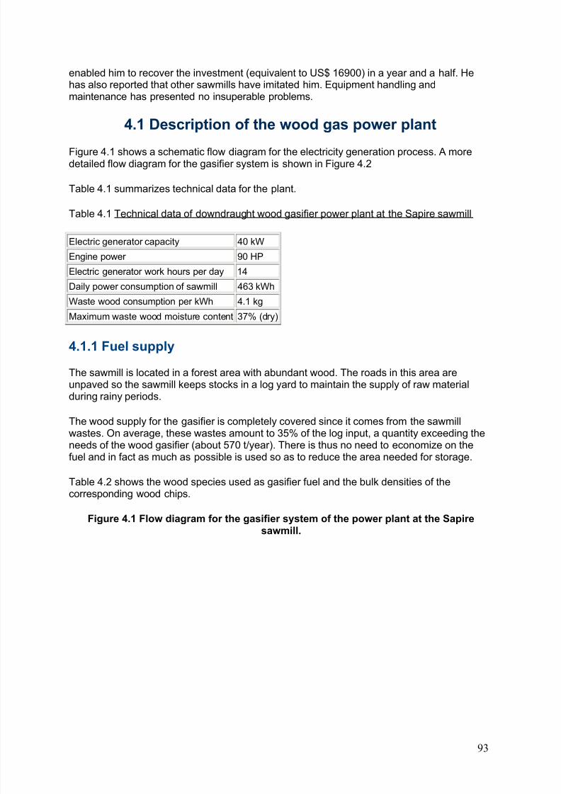
8/6/2019 Gasifier Design
http://slidepdf.com/reader/full/gasifier-design 99/139
enabled him to recover the investment (equivalent to US$ 16900) in a year and a half. Hehas also reported that other sawmills have imitated him. Equipment handling andmaintenance has presented no insuperable problems.
4.1 Description of the wood gas power plant
Figure 4.1 shows a schematic flow diagram for the electricity generation process. A moredetailed flow diagram for the gasifier system is shown in Figure 4.2
Table 4.1 summarizes technical data for the plant.
Table 4.1 Technical data of downdraught wood gasifier power plant at the Sapire sawmill
Electric generator capacity 40 kW
Engine power 90 HP
Electric generator work hours per day 14
Daily power consumption of sawmill 463 kWh
Waste wood consumption per kWh 4.1 kg
Maximum waste wood moisture content 37% (dry)
4.1.1 Fuel supply
The sawmill is located in a forest area with abundant wood. The roads in this area areunpaved so the sawmill keeps stocks in a log yard to maintain the supply of raw materialduring rainy periods.
The wood supply for the gasifier is completely covered since it comes from the sawmillwastes. On average, these wastes amount to 35% of the log input, a quantity exceeding theneeds of the wood gasifier (about 570 t/year). There is thus no need to economize on thefuel and in fact as much as possible is used so as to reduce the area needed for storage.
Table 4.2 shows the wood species used as gasifier fuel and the bulk densities of thecorresponding wood chips.
Figure 4.1 Flow diagram for the gasifier system of the power plant at the Sapiresawmill.
93
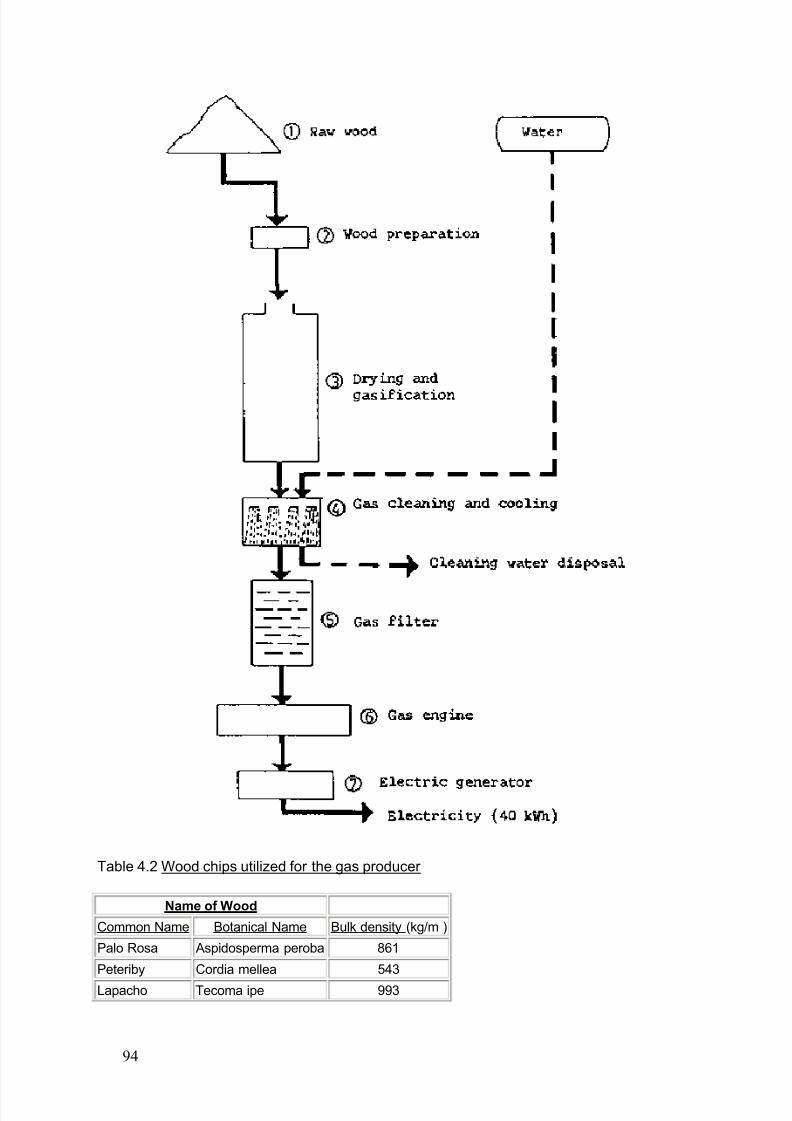
8/6/2019 Gasifier Design
http://slidepdf.com/reader/full/gasifier-design 100/139
Table 4.2 Wood chips utilized for the gas producer
Name of Wood
Common Name Botanical Name Bulk density (kg/m )
Palo Rosa Aspidosperma peroba 861
Peteriby Cordia mellea 543
Lapacho Tecoma ipe 993
94
8/6/2019 Gasifier Design
http://slidepdf.com/reader/full/gasifier-design 101/139
Cedar Cedrella fissilis 554
Guacá Ocotea puberula 448
Guatambu Aspidosperma Austr. 883
The maximum dimensions of the wood fuel are 40 x 40 x 5 cm, i.e. the largest that can befed into the loading chute of the gasifier, and smaller pieces, down to the size of a matchbox,are all accepted. In theory, about ten percent of shavings and sawdust can be included, butin practice this has produced poor results because the sawmill has an earth floor and dusttends to be swept up with the wood waste.
The maximum moisture content recorded was 37 percent, decreasing with size and thelength of time the logs are stored before conversion. The moisture content therefore varieswith sawmill operations and the seasons.
Variations of wood moisture content below the maximum do not affect the quality of fuel gasbecause the feedstock dries in the bunker section of the gasifier before-it reaches the
pyrolysis zone.
4.1.2 The wood gasifier
The wood gas generator consists of a unit with sheet iron walls 6 mm thick lined on theinside with bricks having 50 percent alumina (AL2O3) content. It has a total height of 3600mm and its external diameter is 1400 mm. The fuel (wood) loading chute has a diameter of 400 mm. The reactor has cast iron grates installed 300 mm from the bottom. These gratesare set 20 mm apart and have a lever movement system for removing ashes. Under thegrates, 150 mm from the base, is a water cooling system with a three-fold function as follows:
1. Hydraulically closing off the area where the ashes fall out to prevent the combustible gasfrom leaking.2. Cooling the grate and lever area.3. Draining off the ashes with water.
Figure 4.2 Sketch of the wood gasifier at the Sapire sawmill
The gasifier has eight two-inch diameter air entrance openings. Four of these are separatedat equal intervals of 1800 mm from the bottom. The remaining four are separated in thesame way but at 1320 mm from the bottom (see Figure 4.2).
The gasifier, being moderately large, is able to accept pieces of wood varying in size andmoisture content. The wood load forms a column in which carbonization takes place at thebottom and the convected heat dries the pieces at the top. One fuel load lasts for approximately fourteen hours and can be replenished during operation since the cover of thechute is always left half open.
The moisture content of the fuel should be low, preferably below 25 percent, so that effectiveoxidation of the various pyrolysis products can take place in the oxidation zone. A goodquality fuel gas results.
The ash content is 0.7 to 0.9 percent of the weight of the dry wood. During gasification mostof the ash reaches the grate where it falls into a sheet of water flowing from the cooling
apparatus and is disposed of down a drain. A small part of fly ash is retained in the gas andis removed by cooling.
95
8/6/2019 Gasifier Design
http://slidepdf.com/reader/full/gasifier-design 102/139
4.1.3 Wood gas cooling and washing installations
From a sheet iron receptacle 600 mm in diameter by 1300 mm in height a half-inch water tube with a disc attached at the end having holes like an ordinary shower, sprays water likerain on the hot gases. The water is then discharged into another receptacle where it
becomes atomized by an electrically driven fan turning at 1500 rpm. The same water is thendischarged by gravity into the bottom of the gasifier where, by passing through a row of bricks, it makes an hydraulic seal to prevent the combustible gases from escaping. Lastly,the water circulates, drawing the ashes into drains. The final temperature of the cooling water fluctuates between 75° and 85 C.
4.1.4 Wood gas filter
The gasifier has a cylindrical filter 2650 mm high by 800 mm diameter. The cylinder is filledwith pieces of softwood 35 x 8 x 7 cm in size, reaching to the top of the gas outlet to theengine (see Figure 4.3). The large volume and large surface area of the filter provide an
effective cooling system for the gas which is fed to the engine at about 45 C.Figure 4.3 The gas filter. (Filter material: pieces of softwood)
96
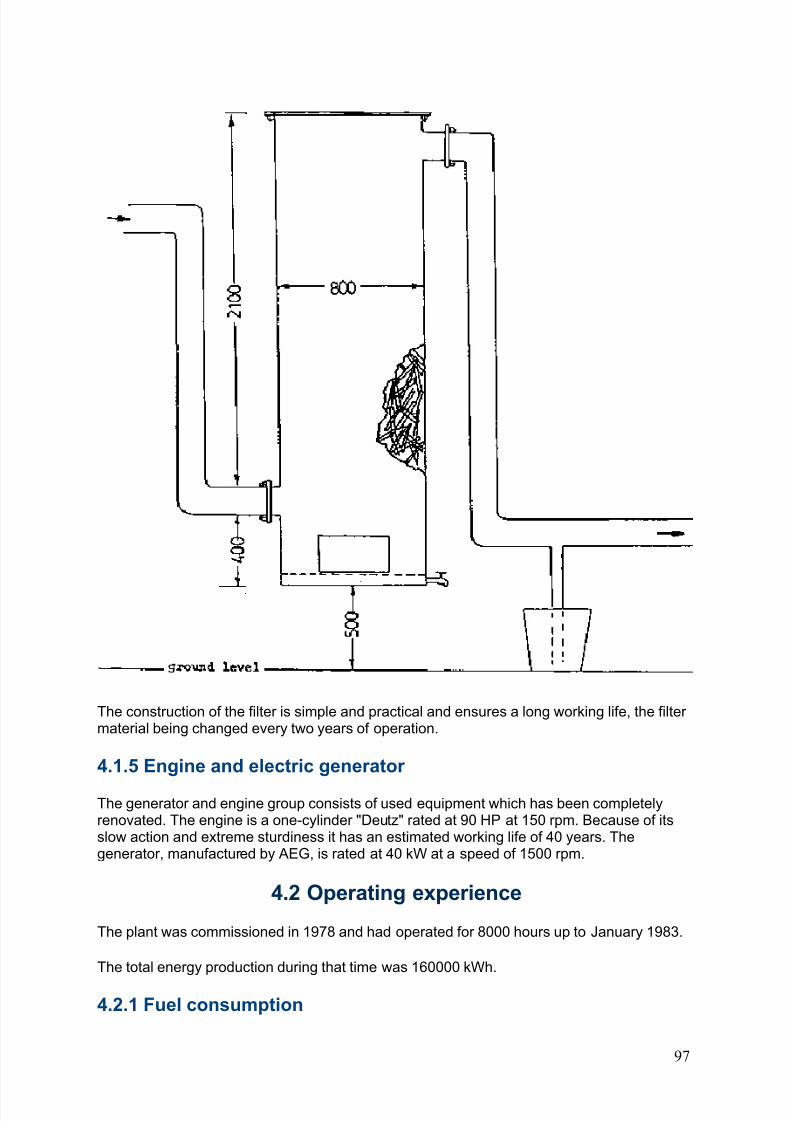
8/6/2019 Gasifier Design
http://slidepdf.com/reader/full/gasifier-design 103/139
8/6/2019 Gasifier Design
http://slidepdf.com/reader/full/gasifier-design 104/139
The average wood consumption of the plant is 4.1 kg/kWh. This is a relatively high figure butit is acceptable indeed desirable - because of the need to keep the sawmill and itssurroundings clear of wood waste. Should the need arise, consumption can be reduced bycontrol of the air flow in the gasifier.
4.2.2 Manpower employed and operating procedureThe equipment is serviced by one operator on a part-time basis, continuous attention is notneeded. In addition, three employees prepare the fuelwood pieces and stoke the gasifier.
The main operations on any one day are as follows:
1. Turning on an impeller fan to start gas production. After some minutes the combustibility of the gas is tested by lighting it with a small flame.
2. Turning on the gas producer engine to supply power to the sawmill.
3. Starting the water pump which supplies the sawmill with the cooling water for thegasifier/generator and the households.
4. General maintenance, including lubrication and charging the compressed air tank inreadiness for the next start-up of the engine.
5. Cleaning of the gasifier and preparation of fuel in sizes suitable for the loading chute.Refuelling of the gasifier is done at noon, half an hour before the end of the first period of work, and again in the evening before the end of the shift.
6. During the afternoon, the operators inspect and service the equipment - lubrication,
storage batteries, cooling water, ash outlet, filter outlet, gas temperature.
7. The sawmill's work day ends at 18.00 hours but the engine and generator continue tooperate until 22.00 hours for the benefit of the small village. Preparations for this have beencompleted during the day, and the operator makes a visit every hour until he stops themachine at 22.00 hours. The gasifier has a sufficient reserve for an immediate start the nextmorning.
4.2.3 Safety
The installation has the following features which help to minimize the usual hazards of
gasifier operation:
1. Excessive internal pressure cannot build-up because the lid of the feeding chute ispermanently left half-open. Should it be operated closed, a quick-release mechanism can beused to relieve pressure.
2. The gasifier is housed in an open shed so that concentrations of carbon monoxide cannotdevelop.
3. Gas is fed to the engine by suction. If leaks develop in the system the gas cannottherefore escape into the air.
4. Ashes and cinders are discharged onto a water bed so there is no risk of fire from these.
98
8/6/2019 Gasifier Design
http://slidepdf.com/reader/full/gasifier-design 105/139
5. The gasifier is sited at a sufficient distance from the sawmill to avoid heating theworkplace.
4.2.4 Environmental impact
A strict analysis of the environmental impact of the gasifier has not been carried out but, asnoted above, simple precautions have effectively eliminated the risks of carbon monoxidepoisoning and fire. Moisture and smoke are vented through the gasifier chimmey which issufficiently high not to cause pollution. Waste water and ashes (1000 l and 19 kg a day) aredischarged downhill to a remote swamp. Finally, the exhaust gas of the engine appears to becleaner than that of an engine operated by diesel fuel.
4.3 Economic evaluation
4.3.1 Capital investment
The initial investment, shown in Table 4.3, was G 2131700 equivalent to US$ 16918 or 423US$/kW. Note that the engine and generator were used and renovated.
An extension of the power line of 150 m to family homes is also included.
4.3.2 Operation and maintenance costs
The person responsible for operation and maintenance of the gas producer equipmentreceives a monthly salary of G 70000. His basic pay is G 60000 and he receives anadditional G 10000 to watch and stop the machine at night while electricity is supplied tofamily homes until 22.00 hours. Taking 25 work-days a month as the base, the daily wage is
G 2800.
Net operating and- maintenance time on the gas producer and electric generator enginegroup corresponds to a half day's work of the operator, the other half being spent onmaintenance tasks elsewhere in the mill. Therefore, only 50% of the mechanic's salary, or G1400 per day, is allocated to the gas producer and electric generator group.
Cost of lubricants is about G 0.84/kWh or 0.0067 US$/kWh.
Spare parts for the engine and gasifier system have an average cost of G 174424 annuallyor 13 percent of the basic investment cost of the equipment (G 1352100).
Note = 1 US$ = 126 G (1982)
99
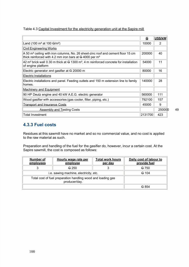
8/6/2019 Gasifier Design
http://slidepdf.com/reader/full/gasifier-design 106/139
Table 4.3 Capital Investment for the electricity generation unit at the Sapire mill
G US$/kW
Land (100 m² at 100 G/m²) 10000 2
Civil Engineering Works
A 50 m² ceiling with iron columns, No. 26 sheet-zinc roof and cement floor 15 cmthick reinforced with 4.2 mm iron bars at G 4000 per m²
200000 40
42 m² brick wall 0.30 m thick at G 1300 m², 4 m reinforced concrete for installationof engine platform
54000 11
Electric generator and gasifier at G 20000 m 80000 16
Electric Installations
Electric installations and panel. Feeding outlets and 150 m extension line to familyhomes.
140000 28
Machinery and Equipment
90 HP Deutz engine and 40 kW A.E.G. electric generator 560000 111Wood gasifier with accessories (gas cooler, filter, piping, etc.) 792100 157
Transport and Insurance Costs 45000 9
Assembly and Testing Costs 250000 49
Total Investment 2131700 423
4.3.3 Fuel costs
Residues at this sawmill have no market and so no commercial value, and no cost is appliedto the raw material as such.
Preparation and handling of the fuel for the gasifier do, however, incur a certain cost. At theSapire sawmill, the cost is composed as follows:
Number of employees
Hourly wage rate per employee
Total work hoursper day
Daily cost of labour toprovide fuel
3 G 250 3 G 750
i.e. sawing machine, electricity, etc. G 104
Total cost of fuel preparation handling wood and loading gasproducer/day.
G 854
100
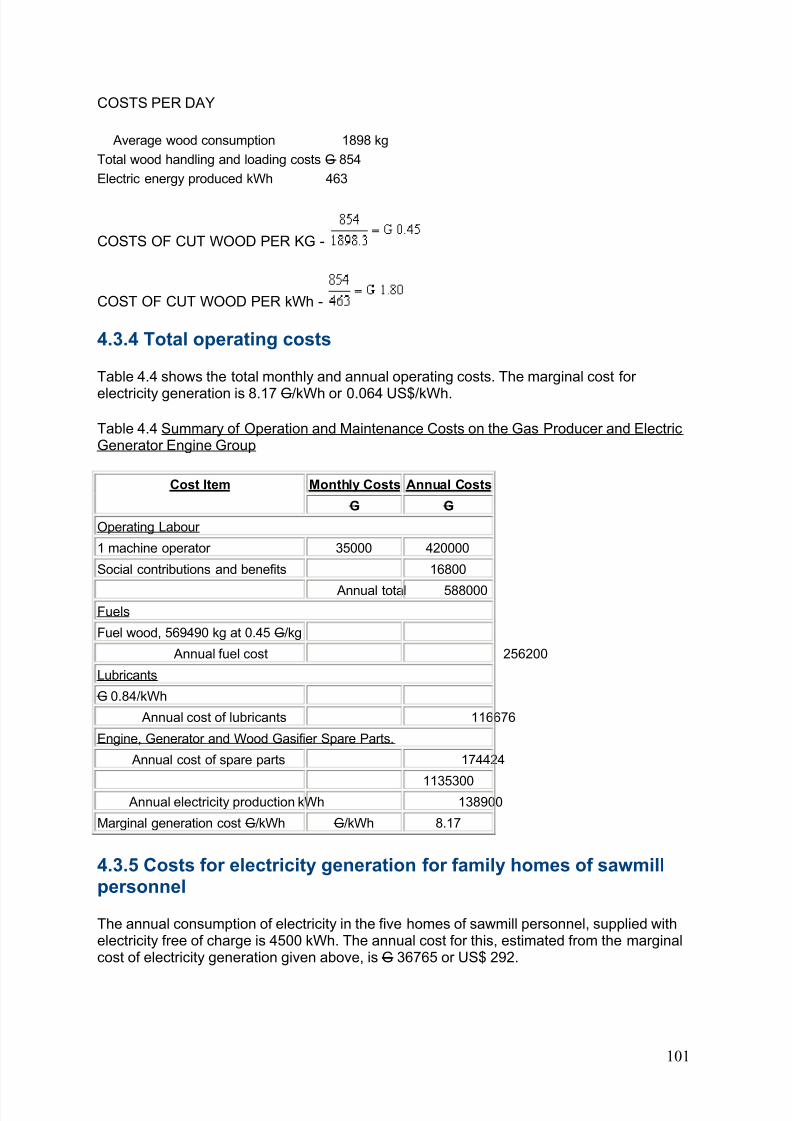
8/6/2019 Gasifier Design
http://slidepdf.com/reader/full/gasifier-design 107/139
COSTS PER DAY
Average wood consumption 1898 kg
Total wood handling and loading costs G 854
Electric energy produced kWh 463
COSTS OF CUT WOOD PER KG -
COST OF CUT WOOD PER kWh -
4.3.4 Total operating costs
Table 4.4 shows the total monthly and annual operating costs. The marginal cost for
electricity generation is 8.17 G/kWh or 0.064 US$/kWh.
Table 4.4 Summary of Operation and Maintenance Costs on the Gas Producer and ElectricGenerator Engine Group
Monthly Costs Annual CostsCost Item
G G
Operating Labour
1 machine operator 35000 420000
Social contributions and benefits 16800
Annual total 588000Fuels
Fuel wood, 569490 kg at 0.45 G/kg
Annual fuel cost 256200
Lubricants
G 0.84/kWh
Annual cost of lubricants 116676
Engine, Generator and Wood Gasifier Spare Parts.
Annual cost of spare parts 174424
1135300 Annual electricity production kWh 138900
Marginal generation cost G/kWh G/kWh 8.17
4.3.5 Costs for electricity generation for family homes of sawmillpersonnel
The annual consumption of electricity in the five homes of sawmill personnel, supplied withelectricity free of charge is 4500 kWh. The annual cost for this, estimated from the marginalcost of electricity generation given above, is G 36765 or US$ 292.
101
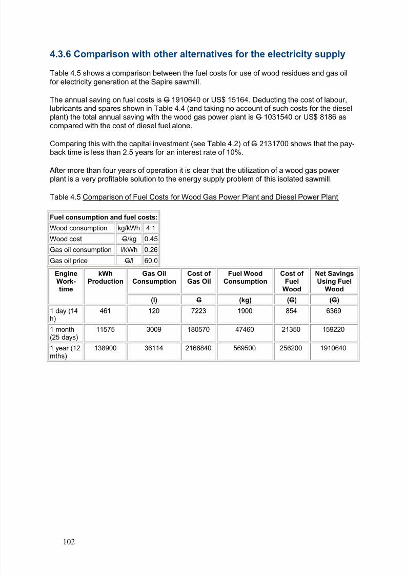
8/6/2019 Gasifier Design
http://slidepdf.com/reader/full/gasifier-design 108/139
4.3.6 Comparison with other alternatives for the electricity supply
Table 4.5 shows a comparison between the fuel costs for use of wood residues and gas oilfor electricity generation at the Sapire sawmill.
The annual saving on fuel costs is G 1910640 or US$ 15164. Deducting the cost of labour,lubricants and spares shown in Table 4.4 (and taking no account of such costs for the dieselplant) the total annual saving with the wood gas power plant is G 1031540 or US$ 8186 ascompared with the cost of diesel fuel alone.
Comparing this with the capital investment (see Table 4.2) of G 2131700 shows that the pay-back time is less than 2.5 years for an interest rate of 10%.
After more than four years of operation it is clear that the utilization of a wood gas power plant is a very profitable solution to the energy supply problem of this isolated sawmill.
Table 4.5 Comparison of Fuel Costs for Wood Gas Power Plant and Diesel Power Plant
Fuel consumption and fuel costs:
Wood consumption kg/kWh 4.1
Wood cost G/kg 0.45
Gas oil consumption l/kWh 0.26
Gas oil price G/l 60.0
Gas OilConsumption
Cost of Gas Oil
Fuel WoodConsumption
Cost of Fuel
Wood
Net SavingsUsing Fuel
Wood
EngineWork-time
kWhProduction
(l) G (kg) (G) (G) 1 day (14h)
461 120 7223 1900 854 6369
1 month(25 days)
11575 3009 180570 47460 21350 159220
1 year (12mths)
138900 36114 2166840 569500 256200 1910640
102
8/6/2019 Gasifier Design
http://slidepdf.com/reader/full/gasifier-design 109/139
Chapter 5 - A small gasifier power plant in Sri Lanka
The gasifier power plant described in this chapter was built by "Biomass Energy Consultantsand Engineers" of The Netherlands. Within the context of the "International Producer GasConference", the plant was installed at Peradeniya University, Sri Lanka, for use as a
demonstration unit during the course on producer gas technology.
By the end of November 1982, it was transferred to the Giriulla Mills for generating electricitybased on coconut shells and providing power to part of a coconut desiccating mill.
Operational data are restricted to the period during which several biomass fuels were testedat Peradeniya University and to the first operational months at Giriulla Mills.
Since the beginning of January 1983, the unit has been operating 20 hours daily, 6 days aweek, except for holidays. Total operational time of the unit (including test runs in theNetherlands, test runs at Peradeniya University and operation at the Giriulla Mills) is
approximately 1200 hours.
5.1 Description of the plant
5.1.1 General system layout
A schematic flow diagram for the power plant is shown in Figure 5.1.
The rated power output is 32 kW.
5.1.2 The gasifier
The gasifier is of the down-draught type with five air entrance openings. The throat diameter is approximately 15 cm, and the general dimensioning of the unit is in accordance with thedesign rules given in Chapter 2.
The throat is made from refractory cement. The inner side of the bunker is air-lined with thismaterial. The hand-operated grate is positioned approximately 20 cm below the smallestcross-sectional area of the throat.
The gasifier is equipped with a double-valve hand operated filling sluice. '
Product gas exchanges heat with incoming air before it is passed on to the gas cleaningsection.
Figure 5.1 Flow diagram for producer gas power plant at the Giriulla mill
The gasifier is equipped with an acoustic fuel level indicator which gives an alarm at the timerefuelling is required.
Gasifier outlet temperatures as well as the pressure drop over the "throat" of the unit can bemeasured. Average values obtained with the different types of fuels tested are given in Table5.1.
5.1.3 Cyclone
103
8/6/2019 Gasifier Design
http://slidepdf.com/reader/full/gasifier-design 110/139
Coarse particles are separated from the gas stream in a high efficiency cyclone separator.Entrained ashes from the gasifier are collected in an ash bin which can be opened at thebottom for regular cleaning.
5.1.4 Impingement separator
Intermediate size particles and most of the fines are removed from the gasifier in animpingement separator of special design. This separator is insulated so as to avoidcondensation of vapours and to allow passage of hot gas (above 150°C) to the glass fibrecloth filter.
5.1.5 Glass fibre cloth filter
To guard the engine against any solid material, the product gas is passed through a glassfibre cloth filter, which removes any solids that have slipped through the previous filter sections.
In order to maintain the temperature above the dew-point of the gas and to avoidcondensation (approximately 80°C) this filter is also insulated with rockwool and analuminium lining.
Both the impingement separator and glass fibre cloth filter are equipped with water gaugemanometers in order to permit the continuous monitoring of pressure drop caused by foulingof the filtering devices.
Originally, the glass fibre cloth filter was equipped with a safety condensate outlet. In Giriullait was found that such a device was unnecessary. Because some water was condensing inthe connection pipe between cooler (see below) and engine air inlet manifold, the drain
vessel was removed from the filter box and put in the connection pipe, where it workedbetter.
5.1.6 Cooler
The cooling section consists of a tubular heat exchanger. Condensate can be tapped fromthe cooler by means of two drain vessels, equipped with safety taps, similar to the onedescribed above. Cooler outlet temperatures vary between 30° and 50°C, depending onenvironmental conditions (temperature, wind) and engine load.
5.1.7 Engine and alternator
Gas is introduced into the engine after being mixed with air in a gas carburettor.
Engine speed is controlled by-means of a Barber-Colman electronic engine speed regulator,which controls simultaneously a gas valve and an air valve. The engine speed is keptconstant at 1500 rpm.
The system is equipped with an International Harvester gas engine (compression ratio 9.5 :1), with a cylinder volume of 9.9 dm³.
The alternator is a short-circuit proof, self-excited internal pole machine in synchronous
construction with the following specifications:
104
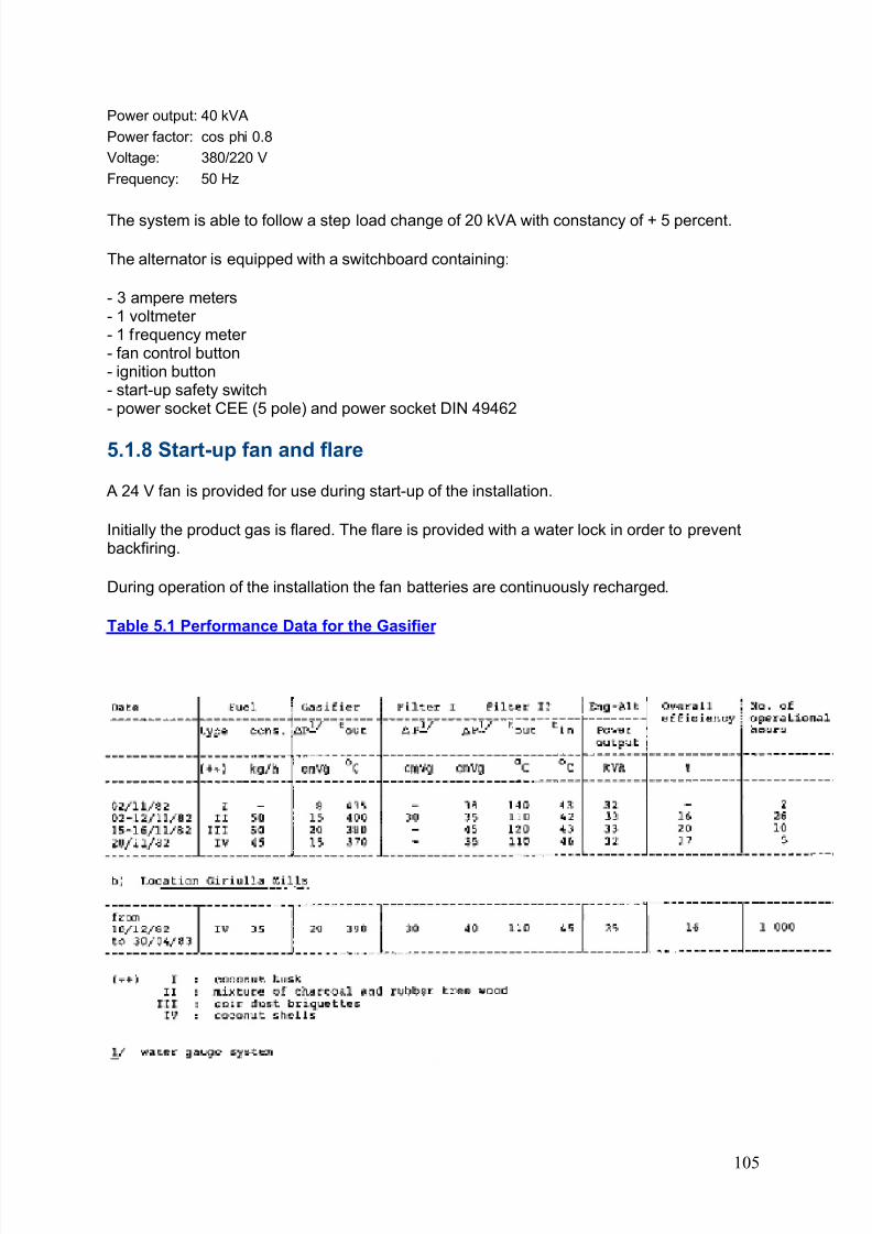
8/6/2019 Gasifier Design
http://slidepdf.com/reader/full/gasifier-design 111/139
Power output: 40 kVA
Power factor: cos phi 0.8
Voltage: 380/220 V
Frequency: 50 Hz
The system is able to follow a step load change of 20 kVA with constancy of + 5 percent.
The alternator is equipped with a switchboard containing:
- 3 ampere meters- 1 voltmeter - 1 frequency meter - fan control button- ignition button- start-up safety switch- power socket CEE (5 pole) and power socket DIN 49462
5.1.8 Start-up fan and flare
A 24 V fan is provided for use during start-up of the installation.
Initially the product gas is flared. The flare is provided with a water lock in order to preventbackfiring.
During operation of the installation the fan batteries are continuously recharged.
Table 5.1 Performance Data for the Gasifier
105
8/6/2019 Gasifier Design
http://slidepdf.com/reader/full/gasifier-design 112/139
5.1.9 Safety devices
The reactor and the filter box are provided with explosion discs.
Operating the start-up fan is not possible with valve E (see Fig. 5.1) opened, thus preventingair from being sucked into the system.
The engine is automatically stopped on loss of oil pressure.
5.1.10 Auxiliaries
The installation is provided with a suitable staircase and fuel feeding platform, in order topermit easy fuel delivery to the gasifier via the double-valve filling sluice. The wholeinstallation is mounted on a base frame and can thus be transported without beingdismantled.
5.2 Operational procedures
5.2.1 Start-up
In order to start-up the unit, the following operations have to be performed:
1. Closing of valve E and opening of valve D (see Fig. 5.1).
2. Opening of the reactor ignition port.
3. Starting the fan by switching the fan button control.
4. Lighting of a piece of paper, that has to be put into the reactor ignition hole. This paper willbe sucked into the gasifier and will ignite the charcoal present in the reactor. It takes about aminute before the charcoal inside the reactor is burning and the ignition hole can be closed.
5. Opening of the gasifier air inlet. Product gas is now escaping through the flare. The gasmust be flared for about ten minutes, before the engine can be started.
6. Switch the fan button to out position, close valve-D and open valve E.
7. Put the air inlet valve to the engine into the half-open position.
8. Close the reactor air-inlet for a short period to create a slight overpressure in the system.
9. Start the engine by pushing the starter button on the control panel.
10. Leave the engine running unloaded for a period of about five minutes.
The whole starting-up procedure takes about twenty minutes.
5.2.2 Closing down
1. Switch off the engine's ignition.
106
8/6/2019 Gasifier Design
http://slidepdf.com/reader/full/gasifier-design 113/139
2. Close valve E.
3. Leave the gasifier air inlet open for a short period in order to release the pressure build-upcaused by continuing pyrolysis of the fuel. Be aware that poisonous carbon-monoxide isbeing produced.
4. After a few minutes close the gasifier air inlet in order to avoid continuous combustion of the reactor's fuel content.
5.2.3 System maintenance
When operating on coconut shells it proved necessary to remove the ashes from the bottomof the reactor every ten operational hours.
The ash bin of the cyclone had to be emptied approximately every forty hours.
From the pressure drop over the impingement separator it became clear that cleaning of thisfiltering device was necessary approximately every 100 hours. Cleaning of the filter proved tobe fairly difficult because of the construction which allows access only at the top of thedevice. The solution was found by removing the dust by means of a vacuum cleaner.
From the pressure drop over the glass fibre filter it was concluded that cleaning of this deviceis necessary approximately every 100 operational hours. Cleaning proved to be a rather tiresome procedure because the top of the filter had to be removed. Removal of the heavytop lid involves at least three persons or alternatively a pulley has to be installed.
The above maintenance can of course be undertaken only when the system is out of operation.
Condensate water must be removed from the condensate drain vessels approximately everyfive hours. This is a minor task and because of the special construction of the drain vesseltaps it can be performed when the system is in operation.
The times given for maintenance intervals depend not only on the operation time of thesystem but on the engine load which is of equal importance. Because the average engineload during operation at Giriulla mills was on the low side (see below), it is entirely possiblethat the intervals between maintenance will be shorter when the system is run under full load.
5.3 Operational experience
5.3.1 Operating record and observations on the performance
The biomass gasification plant was in operation intermittently for about forty hours inNovember 1982 on several fuels at Peradeniya University.
Operational data are presented in Table 5.1
Some tendency to slagging was observed when operating on coconut husks, rubber treewood and coir dust briquettes. Quite possibly this was due to a relatively large amount of sand that was introduced into the gasifier together with the fuel. Regular grid rotation
prevented excessive pressure drop across reactor and bunker, and bunker flow could bemaintained at the de-sired levels.
107
8/6/2019 Gasifier Design
http://slidepdf.com/reader/full/gasifier-design 114/139
At the end of November 1982 the unit was transferred to Giriulla Mills where it has sincebeen operating, fuelled by coconut shells.
Operational data for this period are also summarized in Table 5.1. The system is producingpower for six desiccating motors at a load of up to 30 kVA.
The system can follow a step load change of 20 kVA.
Collected condensate appears to be a clear liquid, indicating that only traces of tarrycomponents are present in the producer gas.
The overall system efficiency was between 15 and 20 percent, as a ratio of output electricalenergy to input biomass energy.
System efficiency is of course dependent on fuel characteristics, load characteristics andenvironmental conditions. The highest efficiency was obtained when operating on coir dustbriquettes; the slagging tendency of this fuel has to be further tested in an extended run, in
order to decide whether automatic and continuous grid rotation is necessary.
At Giriulla Mills the system was continuously operated for about 1000 hours.
From Table 5.1 it is clear that on average the installation was operating at 50 percent of itsfull capacity. From the more detailed data it may be concluded that operation periods atloads of around 33 percent of full capacity are frequent.
5.3.2 Disturbances of the operation
On 19 January 1983 the engine stopped and thereafter it was not possible to operate the
starter motor. The motor was replaced and the engine then started easily.
It is not clear whether this problem stemmed from a defective engine ring gear (which mayhave been faulty from the beginning) or whether the problem has to do with the use of producer gas, which often calls for somewhat prolonged use of the engine's starter motor.
The gasifier operated normally during January and February 1983. However, on severaloccasions the gasifier outlet temperature rose above 475°C, a phenomena which was notaccompanied by higher pressure drops over the gasifier and the filter section. Rotating theash grate did not result in a reduction of the outlet temperature. The engine was stopped for one to two hours on these occasions.
Later (see below), it was possible to attribute the fault to air leakage into the gasifier.
On 4 February, it was noticed that the frequency of refilling with shells had increased fromthe normal 15 minutes to 5-10 minutes. Since the weather had been exceptionally hot anddry from late January onwards, the shells were wetted before loading into the gasifier.Thereafter the frequency of filling returned to the original 15 min.
On 11 February, the engine started misfiring (speed equivalent to 47-50 Hz). Uponreplacement of the spark plugs with new ones the misfiring of the engine stopped.
On 21 February the temperature of the gasifier outlet rose to 500 C. It was noted that tar wasleaking out of the gasifier safety hatch door. Because it wars suspected that air was being
108
8/6/2019 Gasifier Design
http://slidepdf.com/reader/full/gasifier-design 115/139
sucked in through this safety hatch, thus causing the temperature rise, the door was tightlyclosed. This brought down the gasifier outlet temperature to the normal value of 430°C.
It was planned to replace the spring-loaded safety hatch door by a metal explosion disc, as inthe bag house filter.
On 25 February it was noticed that the inside of the inspection hatch (at the gasifier hearthzone) had deteriorated. Therefore an air leak was suspected through this door. A repair wascarried out with mild steel plates as there was a danger of the refractory lining cracking andfalling down. The sealing on the door of the inspection hatch was cleaned. Inspection a weeklater showed that the mild steel plates were holding out.
On 1 March it was noticed that the refractory lining had flaked off at the top and bottomedges. This may have been caused by the frequent cooling/heating cycles. No measureswere taken and the situation seemed to remain stable.
Inspection of the ash pit on 23 March showed a semisolid slag as if the ash had burned in
the ash pit. Air must therefore have been leaking into the gasifier ash-space either throughthe ash outlet or through the grate seal. The grate seal was suspected as it could not betightened. The Giriulla mills-engineer fitted an additional sleeve after which there were nofurther problems.
In February the average engine inlet temperature rose to 50°C, as compared to 42°C inJanuary. Probably this was due to the high ambient temperature in February (on 11 Februaryit was 37° C in the shade and 39°C inside the gasifier shed).
In May 1983 the engine started misfiring again. A change of spark-plugs had no effect. Upondismantling of the engine it was found that the pistons were covered with carbon 1 mm thick.
Also it was noted that the engine inlet manifold was covered with a 2 mm thick semi-solidlayer of either tar or dust/water slurry. The engine's valves appeared to be clean. Themisfiring of the engine was attributed to pre-ignition caused by carbon build-up in-thecylinders.
It is not clear whether the tar production results from the rather low loads at which the engineis now and then operated or stems from an incorrect installation of-the glass fibre cloth filter.
5.3.3 Desirable modifications
The first months of operation revealed the following shortcomings in design and lay-out:
1. The accessibility of the impingement separator is poor and a vacuum cleaner is required toremove the dust.
2. The bag house filter maintenance is difficult. Removal of the top lid requires removal of aflange and the lid is too heavy requiring either three people or a mechanical device to raise it.
3. The grate shaker is not convenient to operate. A lever system which could be operatedwhile standing up would be an improvement.
4. Condensate from the cooling tubes collected in the piping close to the engine inlet. It wasnecessary to fix and additional drain tank to this pipe.
109
8/6/2019 Gasifier Design
http://slidepdf.com/reader/full/gasifier-design 116/139
5. Refractory lining flakes off, probably as a result of the frequent heating/cooling cycle. Thiscould be avoided by supporting the base of the lining with a metal flange.
6. Hot radiator cooling air from the engine is partially directed towards the cooler of thegasifier. This diminishes the effectiveness of the gas cooler.
7. The fuel hopper is too small for coconut shells. It is inconvenient to have to refill the fuelbunker every 15 minutes.
8. The engine's maximum power output is too low. Although the system is designed to deliver 40 kVA, it is possible to get 35 kVA only. This is probably due to the unorthodox system of engine speed control, which controls the gas and the air input to the engine simultaneously,instead of using the normal system where only a gas/air mixture valve is controlled.
Also from general principles it seems possible that the air/gas mixing in the engine's simplegas/air carburettor is not complete, as a result of which some cylinders may get too rich andothers too poor mixture.
5.4 Economic evaluation of electricity generation costs atGiriulla mill
Overall power costs of the system can be calculated on the following assumptions:
System cost US$ 32000 (Hfl. 90000)
System life-time 6 yrs
Interest rate 10%
Maintenance costs 10 percent per year of initial investment 1/
Additional labour costs 1 man-yr Coconut shell costs US$ 6.00/t
Operation 4000 h/yr
Those assumptions lead to the following breakdown of annual costs:
Annual Capital charges 2/ US$ 7350
Maintenance 3200
Additional Labour 700
Lubricants 1600
Fuel (140 ton coconut shell) 840 Annual Cost US$ 13690
Energy produced (4000 h x 20 kW) 80000 kWh
Unitary cost 0.171 US$/kWh
110
8/6/2019 Gasifier Design
http://slidepdf.com/reader/full/gasifier-design 117/139
Those costs compare favourably with a diesel generation system, for which the costs under comparable circumstances would be around 0.26 US$/kWh.
1/ Assumed2/ Annual capital charges are calculated using the relationship:
in which:
C = capital costsi = annual interest ratet = lifetime of system
5.5 Concluding remarks
From the detailed discussion above it will be seen that a number of operational difficultieswere encountered. Those problems are easy to solve and have been remedied in secondgeneration installations.
A major problem could result from the slow carbon build-up in the engine's cylinders as aconsequence of traces of tar or dust in the gas. Whether this is due to too low engine loadsor to a defective glass fibre cloth filter remains to be tested.
The economy of the gasification system in Sri Lanka compares favourably with diesel-electricgenerating systems of the same size.
111
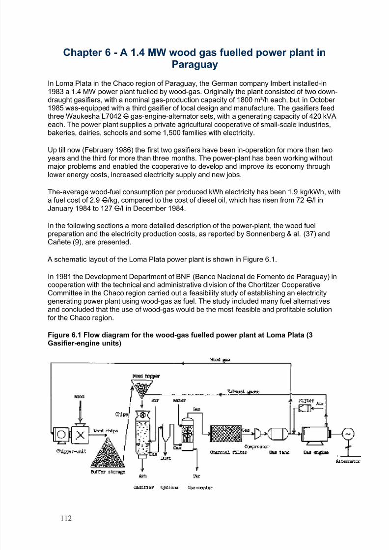
8/6/2019 Gasifier Design
http://slidepdf.com/reader/full/gasifier-design 118/139
Chapter 6 - A 1.4 MW wood gas fuelled power plant inParaguay
In Loma Plata in the Chaco region of Paraguay, the German company Imbert installed-in1983 a 1.4 MW power plant fuelled by wood-gas. Originally the plant consisted of two down-draught gasifiers, with a nominal gas-production capacity of 1800 m³/h each, but in October 1985 was-equipped with a third gasifier of local design and manufacture. The gasifiers feedthree Waukesha L7042 G gas-engine-alternator sets, with a generating capacity of 420 kVAeach. The power plant supplies a private agricultural cooperative of small-scale industries,bakeries, dairies, schools and some 1,500 families with electricity.
Up till now (February 1986) the first two gasifiers have been in-operation for more than twoyears and the third for more than three months. The power-plant has been working withoutmajor problems and enabled the cooperative to develop and improve its economy throughlower energy costs, increased electricity supply and new jobs.
The-average wood-fuel consumption per produced kWh electricity has been 1.9 kg/kWh, witha fuel cost of 2.9 G/kg, compared to the cost of diesel oil, which has risen from 72 G/l inJanuary 1984 to 127 G/l in December 1984.
In the following sections a more detailed description of the power-plant, the wood fuelpreparation and the electricity production costs, as reported by Sonnenberg & al. (37) andCañete (9), are presented.
A schematic layout of the Loma Plata power plant is shown in Figure 6.1.
In 1981 the Development Department of BNF (Banco Nacional de Fomento de Paraguay) incooperation with the technical and administrative division of the Chortitzer CooperativeCommittee in the Chaco region carried out a feasibility study of establishing an electricitygenerating power plant using wood-gas as fuel. The study included many fuel alternativesand concluded that the use of wood-gas would be the most feasible and profitable solutionfor the Chaco region.
Figure 6.1 Flow diagram for the wood-gas fuelled power plant at Loma Plata (3Gasifier-engine units)
112
8/6/2019 Gasifier Design
http://slidepdf.com/reader/full/gasifier-design 119/139
The conclusions were based on the following facts:
1) the possibility of avoiding the use of fossil fuels for electricity generation;
2) creation of new jobs in fuelwood harvesting, transportation and preparation;
3) utilization of the forest residues unsuitable for industrial processing;
4) reducing the costs of farmers preparing new agricultural land by having the possibility tosell the cut wood as fuel;
5) the fuelwood resources of the area will cover the needs of the power plant for a long time;
6) no need of good quality cooling- or boiler water;
7) avoiding the transportation of fuel oil over long distances, with continuously growing costs;
8) considerably lower costs per produced kWh electricity with wood-gas than with diesel oil;
9) savings of foreign currency both on a national and regional level, by decreasing the needfor imported oil;
10) development of regional self-sufficiency in the zone, without being dependent on climateand oil supply (the routes are often closed because of rainfall), and improvement of theeconomy because of smaller oil bills for the power-plant and smaller electricity bills for theindustry in the zone.
Leaning on the facts of the feasibility study the Chortitzer Cooperative decided to ask for a
loan, to realize the wood-gas project, with an estimated total cost of 320 million G. Thiswould be the first power-plant of this size in South America producing electricity with abiomass-based fuel.
The first two years of operation have created great interest among representatives of thegovernment, technical institutions and both national and foreign agents and decision makers,who have paid frequent visits to the Loma Plata power-plant.
6.2 Wood-fuel supply and preparation
The wood-fuel for the plant is supplied from a 274000 ha large forest area, with an estimated
total quantity of 57 million tons of fuelwood and a natural growth rate of 2 - 3 m /ha/a. Withinthe zone under influence the use of fuelwood has grown from 3300 tons in 1981 to 10500tons in 1984. With the third gasifier taken into use, the Loma Plata power plant is projected touse approximately 15000 tons of fuelwood per year. The other biggest fuelwood consumersin the area are the peanut oil and cotton industries, brick and charcoal producers, bakeriesand furniture manufacturers, consuming annually between 600 to 1100 tons each. Thus, thesupply of fuelwood to the power plant will by all probability not be endangered in the near future. The fuelwood resources of the Chaco region are estimated to cover the needs of thepower plant and the industries for more than 3000 years. The fuelwood is brought into theplant from an area of 45 km radius.
The fuelwood delivered to Loma Plata is mainly of Quebracho blanco origin. The diameter of the stems is between 50 and 250 millimetres. It is necessary to provide the gasifier withclean and fairly dry wood-fuel without stones, clay or extra mineral matter; otherwise the ash
113
8/6/2019 Gasifier Design
http://slidepdf.com/reader/full/gasifier-design 120/139
in the gasifier becomes slag and disturbs the gasification process. Therefore an area withhard floor, for the feedstock preparation, is arranged near to the gasifier plant. It isrecommended that trunks of wood are first cut to lengths from 1.5 to 2.5 metres for easier preparing and handling in the wood-fuel comminution system. To accelerate the dryingprocess it is advantageous to split the stems in the open air. A simple hydraulic splitter isused. Before chipping, the moisture content of the fuelwood is on average 40-42% and itdries in sixty days in open air to 28% and covered by a roof to approximately 25% (see table6.1). For practical and safety reasons the plant stores woodfuel for roughly three monthsconsumption within the site.
Table 6.1 Drying properties of the fuelwood (9)
drying time (days) open air M.C. dry (%) covered M.C. dry (%)
0 40.7 40.7
15 34.2 30.7
30 32.3 29.5
45 29.9 27.260 27.2 25.2
The gasifier fuel should preferably be smaller than 70 to 90 millimetres in length of 300 cm involume. A drum chipper, with a capacity of approximately 20 m /h, and driven by a wood-gasengine (Mercedes-Benz, 110 kW power output) is used for this purpose. The chipper has adiameter of 1000 mm and rotates at 1000 rpm. By running it for 4 - 5 hours/day the requiredwoodfuel amount for 24 hours operation can be produced. Table 6.2 shows a normal particlesize distribution of the produced wood chips.
Table 6.2 Particle size distribution of the gasifier-fuel(9)
screen size (mm) retention (%)
150 x 150 4.8
100 x 100 56.0
50 x 50 29.2
25 x 25 9.9
sieving loss 0.1
The bulk density of the wood chips is approximately 400 kg/m³ at 25% moisture content.From the chipper the wood chips are transported to a buffer storage with a conveyor. Thecapacity of this covered buffer is approximately 300 m and its surface area 200 m. Thewoodchips are loaded from the buffer storage into the feed hoppers of the gasifiers with theaid of conveyors. The feed hoppers are equipped to use the exhaust gases from the engines,to further reduce the moisture content of the wood-fuel. The moisture content of the chipsdecreases with 5-10% units after contact with the approximately 150°C hot exhaust gasesduring 12 - 15 minutes. An analysis of 15 samples of wood chips gave an average moisturecontent of 19.2%, with a variation between 10.2 and 28.7%. The size of one feed hopper is 8m, which will suffice for three hours operation, at full gasifier load.
6.3 Description of the down-draught gasifiers
The power-plant of Loma Plata is equipped with three downdraught gasifiers - two of Imbertdesign and one of local with a nominal gas production capacity of 1800 m³/h each. The
114
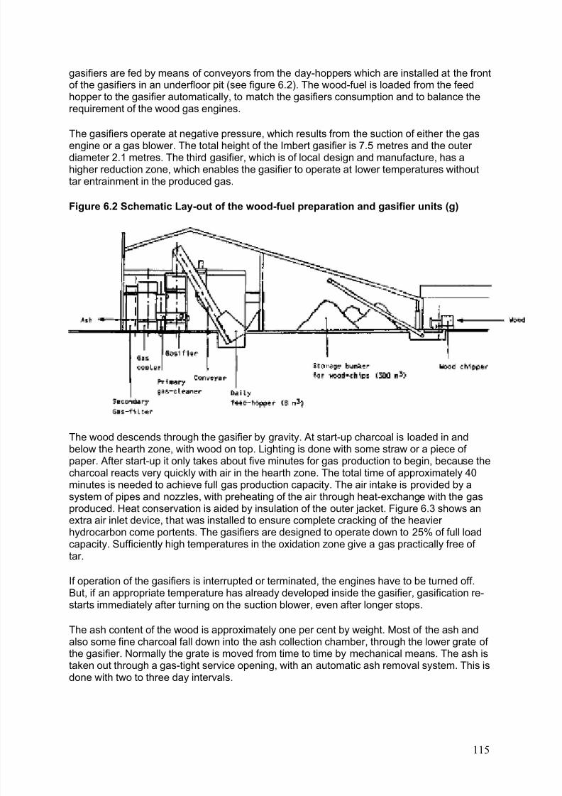
8/6/2019 Gasifier Design
http://slidepdf.com/reader/full/gasifier-design 121/139
gasifiers are fed by means of conveyors from the day-hoppers which are installed at the frontof the gasifiers in an underfloor pit (see figure 6.2). The wood-fuel is loaded from the feedhopper to the gasifier automatically, to match the gasifiers consumption and to balance therequirement of the wood gas engines.
The gasifiers operate at negative pressure, which results from the suction of either the gasengine or a gas blower. The total height of the Imbert gasifier is 7.5 metres and the outer diameter 2.1 metres. The third gasifier, which is of local design and manufacture, has ahigher reduction zone, which enables the gasifier to operate at lower temperatures withouttar entrainment in the produced gas.
Figure 6.2 Schematic Lay-out of the wood-fuel preparation and gasifier units (g)
The wood descends through the gasifier by gravity. At start-up charcoal is loaded in andbelow the hearth zone, with wood on top. Lighting is done with some straw or a piece of paper. After start-up it only takes about five minutes for gas production to begin, because thecharcoal reacts very quickly with air in the hearth zone. The total time of approximately 40minutes is needed to achieve full gas production capacity. The air intake is provided by asystem of pipes and nozzles, with preheating of the air through heat-exchange with the gasproduced. Heat conservation is aided by insulation of the outer jacket. Figure 6.3 shows anextra air inlet device, that was installed to ensure complete cracking of the heavier hydrocarbon come portents. The gasifiers are designed to operate down to 25% of full loadcapacity. Sufficiently high temperatures in the oxidation zone give a gas practically free of
tar.
If operation of the gasifiers is interrupted or terminated, the engines have to be turned off.But, if an appropriate temperature has already developed inside the gasifier, gasification re-starts immediately after turning on the suction blower, even after longer stops.
The ash content of the wood is approximately one per cent by weight. Most of the ash andalso some fine charcoal fall down into the ash collection chamber, through the lower grate of the gasifier. Normally the grate is moved from time to time by mechanical means. The ash istaken out through a gas-tight service opening, with an automatic ash removal system. This isdone with two to three day intervals.
115
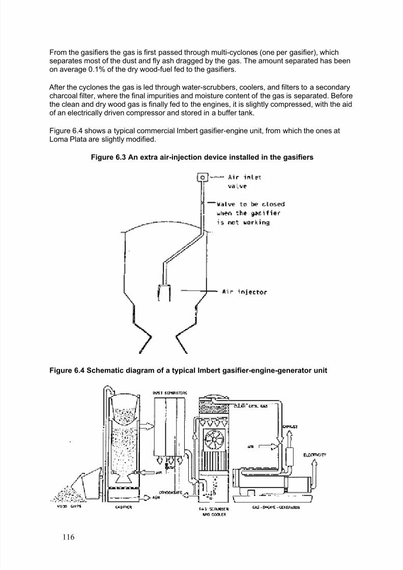
8/6/2019 Gasifier Design
http://slidepdf.com/reader/full/gasifier-design 122/139
From the gasifiers the gas is first passed through multi-cyclones (one per gasifier), whichseparates most of the dust and fly ash dragged by the gas. The amount separated has beenon average 0.1% of the dry wood-fuel fed to the gasifiers.
After the cyclones the gas is led through water-scrubbers, coolers, and filters to a secondarycharcoal filter, where the final impurities and moisture content of the gas is separated. Beforethe clean and dry wood gas is finally fed to the engines, it is slightly compressed, with the aidof an electrically driven compressor and stored in a buffer tank.
Figure 6.4 shows a typical commercial Imbert gasifier-engine unit, from which the ones atLoma Plata are slightly modified.
Figure 6.3 An extra air-injection device installed in the gasifiers
Figure 6.4 Schematic diagram of a typical Imbert gasifier-engine-generator unit
116
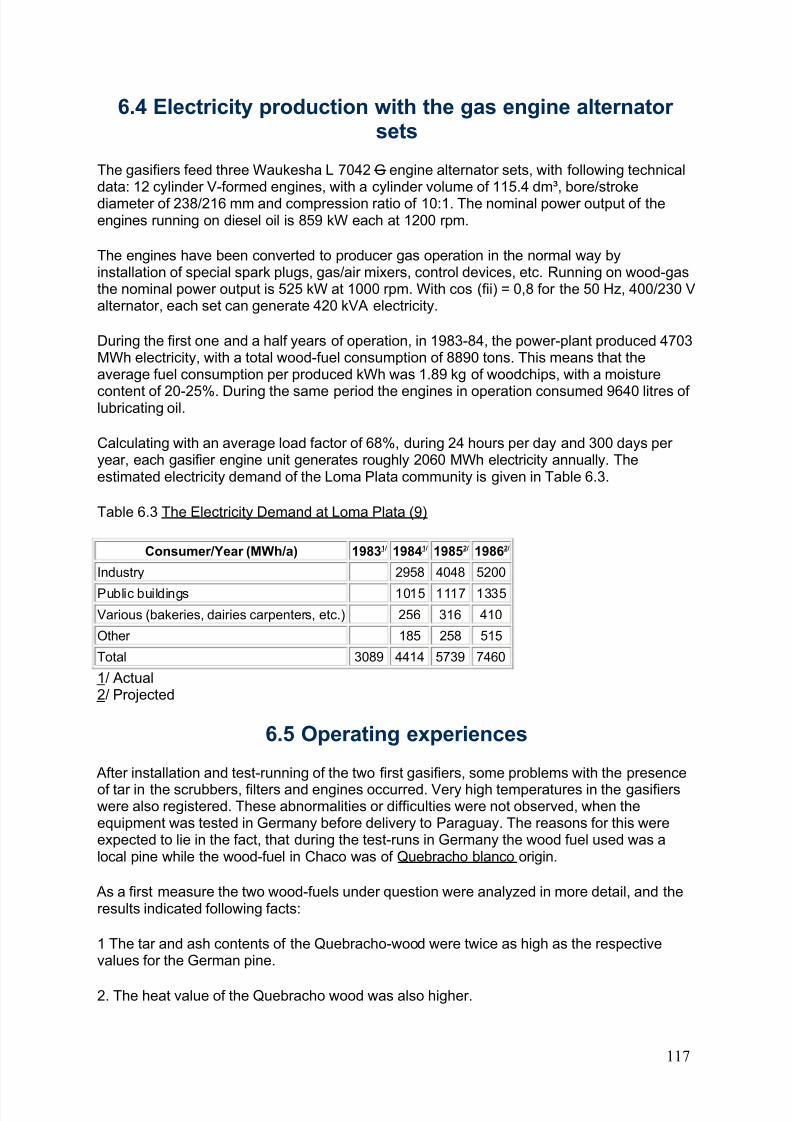
8/6/2019 Gasifier Design
http://slidepdf.com/reader/full/gasifier-design 123/139
6.4 Electricity production with the gas engine alternator sets
The gasifiers feed three Waukesha L 7042 G engine alternator sets, with following technicaldata: 12 cylinder V-formed engines, with a cylinder volume of 115.4 dm³, bore/strokediameter of 238/216 mm and compression ratio of 10:1. The nominal power output of theengines running on diesel oil is 859 kW each at 1200 rpm.
The engines have been converted to producer gas operation in the normal way byinstallation of special spark plugs, gas/air mixers, control devices, etc. Running on wood-gasthe nominal power output is 525 kW at 1000 rpm. With cos (fii) = 0,8 for the 50 Hz, 400/230 Valternator, each set can generate 420 kVA electricity.
During the first one and a half years of operation, in 1983-84, the power-plant produced 4703MWh electricity, with a total wood-fuel consumption of 8890 tons. This means that theaverage fuel consumption per produced kWh was 1.89 kg of woodchips, with a moisture
content of 20-25%. During the same period the engines in operation consumed 9640 litres of lubricating oil.
Calculating with an average load factor of 68%, during 24 hours per day and 300 days per year, each gasifier engine unit generates roughly 2060 MWh electricity annually. Theestimated electricity demand of the Loma Plata community is given in Table 6.3.
Table 6.3 The Electricity Demand at Loma Plata (9)
Consumer/Year (MWh/a) 19831/ 19841/ 19852/ 19862/
Industry 2958 4048 5200
Public buildings 1015 1117 1335Various (bakeries, dairies carpenters, etc.) 256 316 410
Other 185 258 515
Total 3089 4414 5739 7460
1/ Actual2/ Projected
6.5 Operating experiences
After installation and test-running of the two first gasifiers, some problems with the presence
of tar in the scrubbers, filters and engines occurred. Very high temperatures in the gasifierswere also registered. These abnormalities or difficulties were not observed, when theequipment was tested in Germany before delivery to Paraguay. The reasons for this wereexpected to lie in the fact, that during the test-runs in Germany the wood fuel used was alocal pine while the wood-fuel in Chaco was of Quebracho blanco origin.
As a first measure the two wood-fuels under question were analyzed in more detail, and theresults indicated following facts:
1 The tar and ash contents of the Quebracho-wood were twice as high as the respectivevalues for the German pine.
2. The heat value of the Quebracho wood was also higher.
117
8/6/2019 Gasifier Design
http://slidepdf.com/reader/full/gasifier-design 124/139
To solve the above-mentioned problems with tar contamination an extra air-injection device,as shown in figure 6.3, was installed in the gasifier, and an extra secondary charcoal filter was taken into use. To be able to lower the temperatures in the reactor the gas volume hadto be decreased by 30%. This of course had a negative influence on the gasifier capacity. Inthe design of the third gasifier unit, these experiences were taken into account and resultedin a somewhat modified outfit, as mentioned in Section 6.3. In 1985 the gasifiers haveworked more or less trouble-free and the maintenance and repair costs have decreased byroughly 40%. (9)
6.6 Profitability of using wood gas at Loma Plata
The generation of electricity with wood gas at Loma Plata has turned out to be a successfuland profitable operation, compared to the alternative of using diesel oil as a fuel. The price of diesel oil has gone up from 72 G/l in June 1983 to 127 G/l in December 1984. During thisperiod the cost of the wood chips has been on average 2.9 G/kg, which is more than sixtimes the price of wood-fuel at the Sapire sawmill (see Chapter 4), but is still a veryfavourable cost compared to the price of diesel oil.
Production of 1 kWh electricity consumes 1.89 kg of wood-fuel at a cost of 5.48 G, while thecorresponding number for diesel oil would be 0.34 l and 34 G, calculating with an average oilprice of 100 G/l.
Table 6.4 Electricity Generation Costs Using Wood Gas at Loma Plata (9)
Year Wood-fuel G Lubricants G Operation G Maintenance G Total G
1983 4212365 897000 1581216 916850 7667431
1984 21542100 3923000 4671000 18337000 48473100
Total 25814465 4820000 6252216 19253850 56140531
During this period the total electricity production was 4703650 kWh, which gives an average unitcost of 11.93 G/kWh. The share of the lubricating oil of the final costs was 1.02 G/kWh, and theshare of the maintenance costs 4.09 G/kWh. The total investment costs of the power-plant(excluding the third gasifier unit) was 319 million G and the share of the equipment costs 208million G.
Calculating with a real interest rate of 10% and a depreciation time of eight years the annualcapital costs for the installations are 59.3 M G or equivalent to 11.9 G/kWh, with an estimatedaverage electricity production of 5000 MWh per year. This means total electricity production
costs of 23.8 G/kWh, which is only half of the actual electricityprice of 1984, 46 G/kWh.
The pay-back time for the whole project has been estimated toroughly 6.5 years. The net annual savings in fuel costs by usingwood instead of diesel-oil for year 1984 was over 100 million G.
All the economic numbers calculated above, clearly indicate theprofitability of using wood-gas for electricity generation at theLoma Plata power-plant. The other positive socio-economicimpacts of using biomass-based power generation on theagricultural and industrial activity within the Chortitzer cooperative
are dificult to express in numbers but are obvious.
Exchange Rates
June 1983 1 US$ = 160
June 1984 1 US$ = 360
September 1984 1 US$ = 445
January 1985 1 US$ = 377
April 1985 1 US$ = 455
July 1985 1 US$ = 625
January 1986 1 US$ = 635
118
8/6/2019 Gasifier Design
http://slidepdf.com/reader/full/gasifier-design 125/139
Chapter 7 - The future of wood gas as engine fuel
7.1 Prerequisites for extensive use of wood gasifiers
There should be no doubt that wood gasifiers have played an important role in the past,when liquid fuels for internal combustion engines were unavailable or expensive. It is alsoobvious that there has been an increasing interest in this technology since the middle of theseventies among scientists, energy planners, international development assistance agenciesand government officials in some countries as a means of reducing the oil bill in oil importingcountries with large biomass resources. But so far there are very few installations incommercial operation, where the gas is used to operate an internal combustion engine.
It is clear that the technology can have a future role in oil importing countries as anemergency option even though Sweden appears to be the only country which has officiallytaken the decision to make preparations for a conversion of vehicles to wood gas operation.
By all probability wood gas will not have a future as a regular engine fuel. Table 7.1 listscritical questions which all must be answered with 'yes' if its more general use is to bepromoted. Answers based on the present situation in Sweden and in the Third World and abrief discussion of possible changes of the present situation are also provided.
7.2 Industrialized countries
In Sweden the present unfavourable economic situation for wood gasification is the mainreason why there are only a few plants for testing purposes in operation. The unfavourableeconomy is a consequence of the fact that the cost difference between petroleum fuels andelectricity on the one hand and fuel wood on the other is not high enough to cover the high
labour and capital costs of the gasifier system.
It is an interesting observation that the price of petroleum fuels in constant value in Swedenis presently not much different from what it was in the 1930's and is in fact lower than justafter the Second World War. Only during the war was the price significantly higher. Ingeneral, similarly unfavourable economic conditions apply for wood gasifiers in mostcountries in the industrialized world with the possible exception of industries with a surplus of residual biomass fuels.
The situation will change only if there are substantial increases in oil prices or in the cost of electricity. Such a development is foreseen in the present energy policy of Sweden, whichaims at increasing taxes on imported fuels and abolishing nuclear power before the year 2010, but it is not until after the year 2000 that economic conditions may have changed infavour of wood gasifiers.
It can be concluded that there appears to be no immediate future for wood gas as engine fuelin the industrialized countries. Wood gasifiers may be economic under some specialcircumstances, like at industries with a surplus of biomass residues but the impact on theenergy balance will be negligible. This does not mean that there is no need to keep thetechnology alive and improve on it. The situation may have changed by the end of thecentury, and wood gasification is still the only realistic emergency alternative for manycountries.
7.3 Developing countries
119
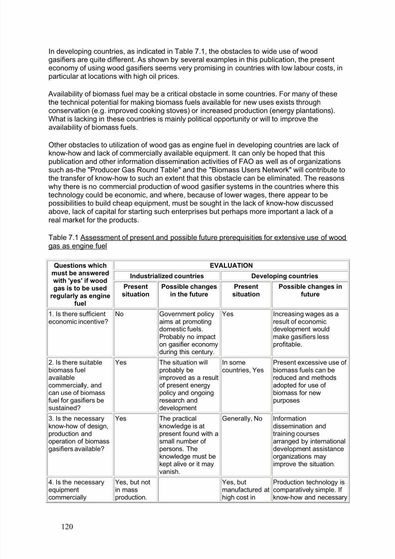
8/6/2019 Gasifier Design
http://slidepdf.com/reader/full/gasifier-design 126/139
In developing countries, as indicated in Table 7.1, the obstacles to wide use of woodgasifiers are quite different. As shown by several examples in this publication, the presenteconomy of using wood gasifiers seems very promising in countries with low labour costs, inparticular at locations with high oil prices.
Availability of biomass fuel may be a critical obstacle in some countries. For many of thesethe technical potential for making biomass fuels available for new uses exists throughconservation (e.g. improved cooking stoves) or increased production (energy plantations).What is lacking in these countries is mainly political opportunity or will to improve theavailability of biomass fuels.
Other obstacles to utilization of wood gas as engine fuel in developing countries are lack of know-how and lack of commercially available equipment. It can only be hoped that thispublication and other information dissemination activities of FAO as well as of organizationssuch as-the "Producer Gas Round Table" and the "Biomass Users Network" will contribute tothe transfer of know-how to such an extent that this obstacle can be eliminated. The reasonswhy there is no commercial production of wood gasifier systems in the countries where this
technology could be economic, and where, because of lower wages, there appear to bepossibilities to build cheap equipment, must be sought in the lack of know-how discussedabove, lack of capital for starting such enterprises but perhaps more important a lack of areal market for the products.
Table 7.1 Assessment of present and possible future prerequisities for extensive use of woodgas as engine fuel
EVALUATION
Industrialized countries Developing countries
Questions whichmust be answeredwith 'yes' if woodgas is to be used
regularly as enginefuel
Present
situation
Possible changes
in the future
Present
situation
Possible changes in
future
1. Is there sufficienteconomic incentive?
No Government policyaims at promotingdomestic fuels.Probably no impacton gasifier economyduring this century.
Yes Increasing wages as aresult of economicdevelopment wouldmake gasifiers lessprofitable.
2. Is there suitablebiomass fuelavailablecommercially, and
can use of biomassfuel for gasifiers besustained?
Yes The situation willprobably beimproved as a resultof present energy
policy and ongoingresearch anddevelopment
In somecountries, Yes
Present excessive use of biomass fuels can bereduced and methodsadopted for use of
biomass for newpurposes
3. Is the necessaryknow-how of design,production andoperation of biomassgasifiers available?
Yes The practicalknowledge is atpresent found with asmall number of persons. Theknowledge must bekept alive or it mayvanish.
Generally, No Informationdissemination andtraining coursesarranged by internationaldevelopment assistanceorganizations mayimprove the situation.
4. Is the necessary
equipmentcommercially
Yes, but not
in massproduction.
Yes, but
manufactured athigh cost in
Production technology is
comparatively simple. If know-how and necessary
120
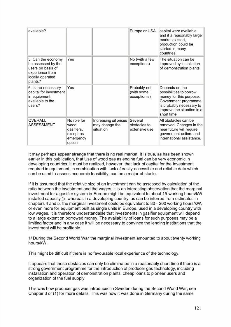
8/6/2019 Gasifier Design
http://slidepdf.com/reader/full/gasifier-design 127/139
available? Europe or USA. capital were availableand if a reasonably largemarket existed,production could bestarted in manycountries.
5. Can the economybe assessed by theusers on basis of experience fromlocally operatedplants?
Yes No (with a fewexceptions)
The situation can beimproved by installationof demonstration plants.
6. Is the necessarycapital for investmentin equipmentavailable to theusers?
Yes Probably not(with someexception s)
Depends on thepossibilities to borrowmoney for this purpose.Government programmeis probably necessary toimprove the situation in a
short timeOVERALL ASSESSMENT
No role for woodgasifiers,except asemergencyoption.
Increasing oil pricesmay change thesituation
Severalobstacles toextensive use
All obstacles can beremoved. Changes in thenear future will requiregovernment action. andinternational assistance.
It may perhaps appear strange that there is no real market. It is true, as has been shownearlier in this publication, that Use of wood gas as engine fuel can be very economic indeveloping countries. It must be realized, however, that lack of capital for the investmentrequired in equipment, in combination with lack of easily accessible and reliable data whichcan be used to assess economic feasibility, can be a major obstacle.
If it is assumed that the relative size of an investment can be assessed by calculation of theratio between the investment and the wages, it is an interesting observation that the marginalinvestment for a gasifier system in Europe might be equivalent to about 15 working hours/kWinstalled capacity 1/, whereas in a developing country, as can be inferred from estimates inchapters 4 and 5, the marginal investment could be equivalent to 80 - 200 working hours/kW,or even more for equipment built as single units in Europe, used in a developing country withlow wages. It is therefore understandable that investments in gasifier equipment will dependto a large extent on borrowed money. The availability of loans for such purposes may be alimiting factor and in any case it will be necessary to convince the lending institutions that the
investment will be profitable.
1/ During the Second World War the marginal investment amounted to about twenty workinghours/kW.
This might be difficult if there is no favourable local experience of the technology.
It appears that these obstacles can only be eliminated in a reasonably short time if there is astrong government programme for the introduction of producer gas technology, includinginstallation and operation of demonstration plants, cheap loans to pioneer users andorganization of the fuel supply.
This was how producer gas was introduced in Sweden during the Second World War, seeChapter 3 or (1) for more details. This was how it was done in Germany during the same
121

8/6/2019 Gasifier Design
http://slidepdf.com/reader/full/gasifier-design 128/139
period, see Graf (16), and this is how it is now done in the Philippines, see Baja (4). Theprogramme in the Philippines has been focussed on charcoal gasification but the sameintroduction problems will affect wood gasifiers.
The conclusion is that the future of wood gasification technology in developing countriesdepends mainly on whether or not there will be government initiatives to promote thistechnology to substitute imported petroleum fuels with biomass. It will probably also benecessary that such programmes receive financial support from international developmentassistance organizations. At present such support is provided to demonstration projects in alarge number of countries, and it can perhaps be expected that this will develop into supportfor programmes with a broader scope.
The World Bank, for the United Nations Development Programme (UNDP), initiated in July1983 a programme to monitor and compile uniform data on the actual field performance,reliability, economics, safety and public acceptability of biomass gasifiers currently operatingin developing countries (29).
The results of the monitoring programme will be used to:
(i) determine if gasifiers are meeting the technical, economic and operational expectations of those currently utilizing the technology;
(ii) identify the gasifier technologies, fuel resources and operating conditions most likely toensure successful projects;
(iii) identify aspects of the technology in need of additional research and development;
(iv) establish standards to evaluate the acceptability of proposed gasifier projects; and
(v) define the scope for the application of biomass gasifiers in developing countries.
The project will ideally encompass a three-year period. During the first phase of theprogramme, the gasified installations listed in Table 7.2 will be monitored (29), and thegroundwork for the effective monitoring of six UNDP/EEC power gasifier projects in theSouth Pacific will be laid. The second year will continue the first mentioned activities, initiatefull-scale monitoring of installed South Pacific gasifiers and possibly add to the programmeexisting installations in Latin America and Africa. In addition, country case studies that definethe role of gasifier technology in meeting national energy needs will be prepared for Braziland the Philippines. Finally, monitoring of the newly emerging heat gasifier technology will besubstituted in the third year.
122
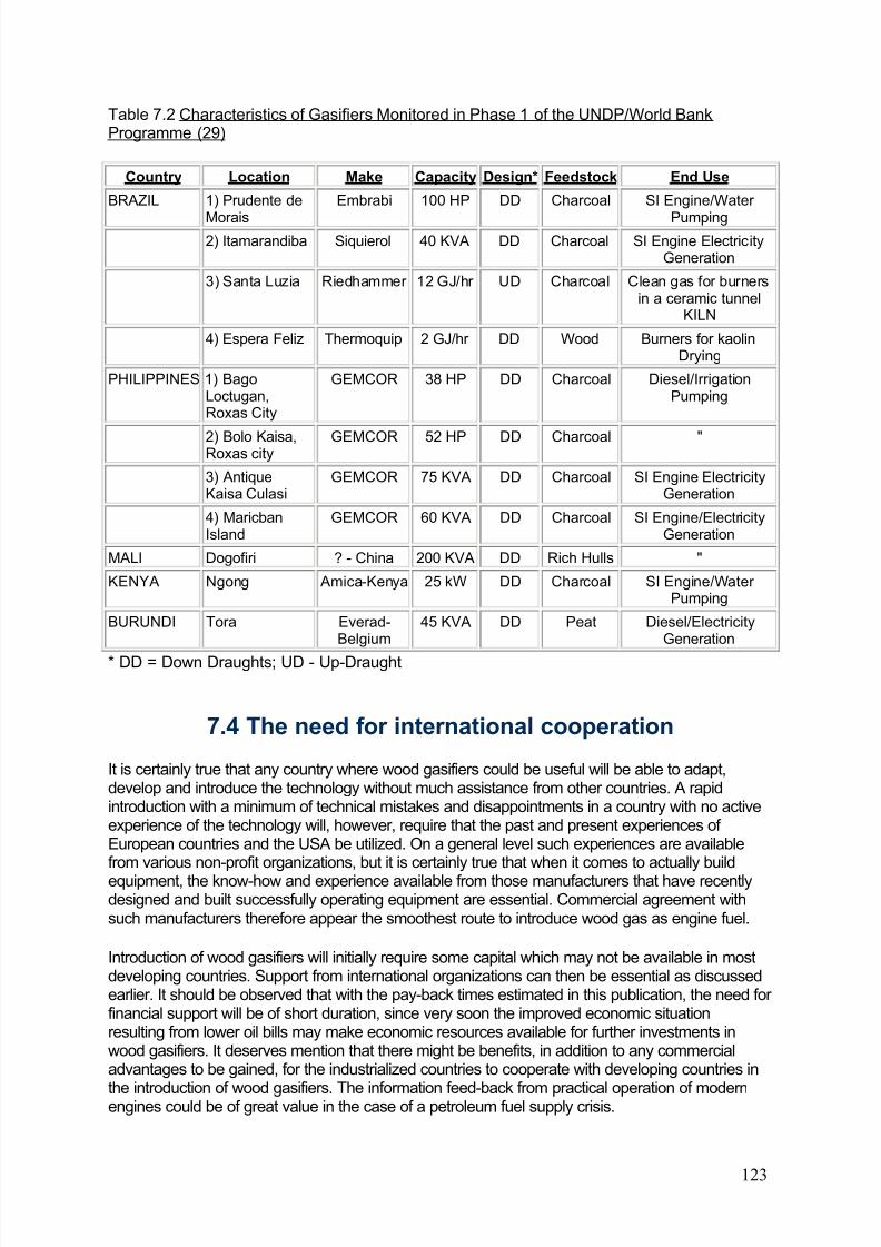
8/6/2019 Gasifier Design
http://slidepdf.com/reader/full/gasifier-design 129/139
Table 7.2 Characteristics of Gasifiers Monitored in Phase 1 of the UNDP/World BankProgramme (29)
Country Location Make Capacity Design* Feedstock End Use
BRAZIL 1) Prudente de
Morais
Embrabi 100 HP DD Charcoal SI Engine/Water
Pumping2) Itamarandiba Siquierol 40 KVA DD Charcoal SI Engine Electricity
Generation
3) Santa Luzia Riedhammer 12 GJ/hr UD Charcoal Clean gas for burnersin a ceramic tunnel
KILN
4) Espera Feliz Thermoquip 2 GJ/hr DD Wood Burners for kaolinDrying
PHILIPPINES 1) BagoLoctugan,Roxas City
GEMCOR 38 HP DD Charcoal Diesel/IrrigationPumping
2) Bolo Kaisa,Roxas city GEMCOR 52 HP DD Charcoal "
3) AntiqueKaisa Culasi
GEMCOR 75 KVA DD Charcoal SI Engine ElectricityGeneration
4) MaricbanIsland
GEMCOR 60 KVA DD Charcoal SI Engine/ElectricityGeneration
MALI Dogofiri ? - China 200 KVA DD Rich Hulls "
KENYA Ngong Amica-Kenya 25 kW DD Charcoal SI Engine/Water Pumping
BURUNDI Tora Everad-Belgium
45 KVA DD Peat Diesel/ElectricityGeneration
* DD = Down Draughts; UD - Up-Draught
7.4 The need for international cooperation
It is certainly true that any country where wood gasifiers could be useful will be able to adapt,develop and introduce the technology without much assistance from other countries. A rapidintroduction with a minimum of technical mistakes and disappointments in a country with no activeexperience of the technology will, however, require that the past and present experiences of European countries and the USA be utilized. On a general level such experiences are availablefrom various non-profit organizations, but it is certainly true that when it comes to actually buildequipment, the know-how and experience available from those manufacturers that have recentlydesigned and built successfully operating equipment are essential. Commercial agreement withsuch manufacturers therefore appear the smoothest route to introduce wood gas as engine fuel.
Introduction of wood gasifiers will initially require some capital which may not be available in mostdeveloping countries. Support from international organizations can then be essential as discussedearlier. It should be observed that with the pay-back times estimated in this publication, the need for financial support will be of short duration, since very soon the improved economic situationresulting from lower oil bills may make economic resources available for further investments inwood gasifiers. It deserves mention that there might be benefits, in addition to any commercialadvantages to be gained, for the industrialized countries to cooperate with developing countries in
the introduction of wood gasifiers. The information feed-back from practical operation of modernengines could be of great value in the case of a petroleum fuel supply crisis.
123
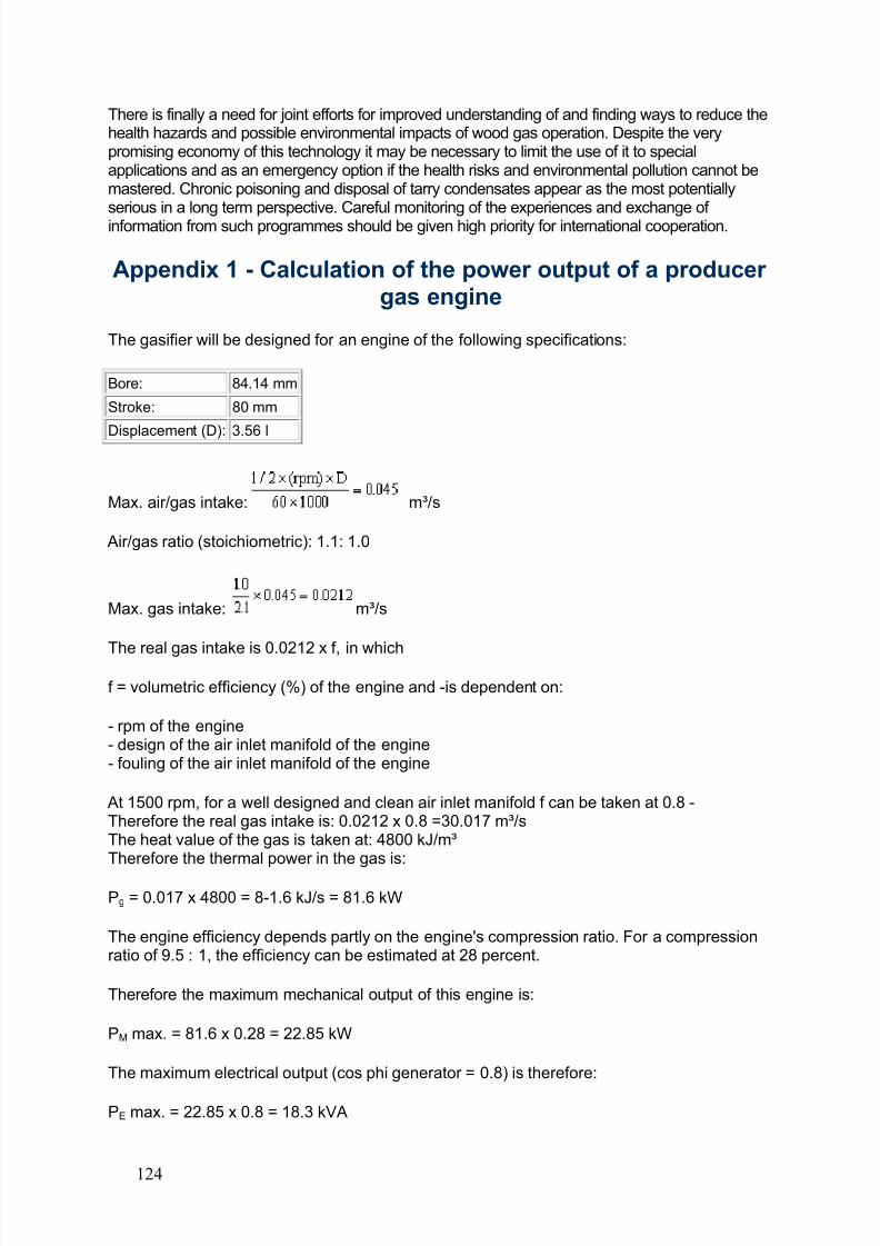
8/6/2019 Gasifier Design
http://slidepdf.com/reader/full/gasifier-design 130/139
There is finally a need for joint efforts for improved understanding of and finding ways to reduce thehealth hazards and possible environmental impacts of wood gas operation. Despite the verypromising economy of this technology it may be necessary to limit the use of it to specialapplications and as an emergency option if the health risks and environmental pollution cannot bemastered. Chronic poisoning and disposal of tarry condensates appear as the most potentiallyserious in a long term perspective. Careful monitoring of the experiences and exchange of information from such programmes should be given high priority for international cooperation.
Appendix 1 - Calculation of the power output of a producer gas engine
The gasifier will be designed for an engine of the following specifications:
Bore: 84.14 mm
Stroke: 80 mm
Displacement (D): 3.56 l
Max. air/gas intake: m³/s
Air/gas ratio (stoichiometric): 1.1: 1.0
Max. gas intake: m³/s
The real gas intake is 0.0212 x f, in which
f = volumetric efficiency (%) of the engine and -is dependent on:
- rpm of the engine- design of the air inlet manifold of the engine- fouling of the air inlet manifold of the engine
At 1500 rpm, for a well designed and clean air inlet manifold f can be taken at 0.8 -Therefore the real gas intake is: 0.0212 x 0.8 =30.017 m³/sThe heat value of the gas is taken at: 4800 kJ/m³Therefore the thermal power in the gas is:
Pg = 0.017 x 4800 = 8-1.6 kJ/s = 81.6 kW
The engine efficiency depends partly on the engine's compression ratio. For a compressionratio of 9.5 : 1, the efficiency can be estimated at 28 percent.
Therefore the maximum mechanical output of this engine is:
PM max. = 81.6 x 0.28 = 22.85 kW
The maximum electrical output (cos phi generator = 0.8) is therefore:
PE max. = 22.85 x 0.8 = 18.3 kVA
124
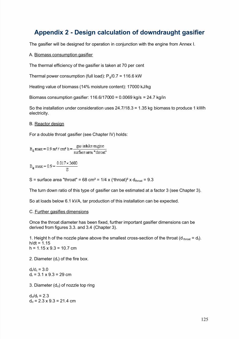
8/6/2019 Gasifier Design
http://slidepdf.com/reader/full/gasifier-design 131/139
Appendix 2 - Design calculation of downdraught gasifier
The gasifier will be designed for operation in conjunction with the engine from Annex I.
A. Biomass consumption gasifier
The thermal efficiency of the gasifier is taken at 70 per cent
Thermal power consumption (full load): Pg/0.7 = 116.6 kW
Heating value of biomass (14% moisture content): 17000 kJ/kg
Biomass consumption gasifier: 116.6/17000 = 0.0069 kg/s = 24.7 kg/in
So the installation under consideration uses 24.7/18.3 = 1.35 kg biomass to produce 1 kWhelectricity.
B. Reactor design
For a double throat gasifier (see Chapter IV) holds:
S = surface area "throat" = 68 cm² = 1/4 x (dthroat)² x dthroat = 9.3
The turn down ratio of this type of gasifier can be estimated at a factor 3 (see Chapter 3).
So at loads below 6.1 kVA, tar production of this installation can be expected.
C. Further gasifies dimensions
Once the throat diameter has been fixed, further important gasifier dimensions can bederived from figures 3.3. and 3.4 (Chapter 3).
1. Height h of the nozzle plane above the smallest cross-section of the throat (dthroat = dt).h/dt = 1.15h = 1.15 x 9.3 = 10.7 cm
2. Diameter (dr ) of the fire box.
dr /dt = 3.0dr = 3.1 x 9.3 = 29 cm
3. Diameter (drl) of nozzle top ring
drl/dt = 2.3drl = 2.3 x 9.3 = 21.4 cm
125
8/6/2019 Gasifier Design
http://slidepdf.com/reader/full/gasifier-design 132/139
4. Nozzle diameter (dn)
Assumption: gasifier to be equipped with 5 nozzles
Total nozzle area (An): 5 x 1/4 x x dn²
dn = 10.4 mm
Table of conversion factors and symbols (used in this manual)
Energy Units
J = Joule
kJ = 1000 J
GJ = 1000000000 J
kWh = 3600000J
TWh = 3.6 x 10¹⁵ J
Power Units
W = Watt
kW = 1000 W
MW = 1000000 W
HP = Horse Power = 745.7 W
kVA = kilo Volt-Ampere
Force Units
N = Newton
kgf = force kilogram1 kgf = 9.8067 N
t = ton = 1000 kgf
Pressure Units
Pa = Pascal = N/m²
kgf/cm² = 98067 Pa
mm Wg = 9.8067 Pacm Wg = 98.067 Pa
atm =1.0133 x 10⁵ Pa
Length Units
m = meter
cm = 0.1 m
mm = 0.001 m
km = 1000 m
m = 0.000.001 m
Surface Units m²= square meter
126
8/6/2019 Gasifier Design
http://slidepdf.com/reader/full/gasifier-design 133/139
cm = 0.01 m
Mass Units
kg = kilogram
mg = 0.000.001 kg
g = 0.001 kgTime Units
s = second
min = minute = 60 s
h = hour = 3600 s
yr = year
Volume Units
m³ = cubic meter
dm³ = 0.001 m³
mm³ = 0.000000001 m³1 = litre = 1 dm³
Temperature Units
K = Kelvin
°C = degree Celsius
1° C = 1 K
Miscellaneous
Nm³ = normal cubic metre (at 1 atm and 0°C)
mol = quantity of matter unit
gram atom = atomic weight expressed in gramsgram molecule = molecular weight expressed in grams
ppm = parts per million
rpm = revolutions per minute
° = angular degrees
person-km = one person transported one km
ton-km = one ton transported one km
man-yr = one man working one year
Other Units
Hz = Hertz (frequency)V = Volt
Currencies
US$ = U.S.A. dollars
G = Guaranies
Hfl = Dutch florin
127
8/6/2019 Gasifier Design
http://slidepdf.com/reader/full/gasifier-design 134/139
References
1. Axelsson, R. 1969a. Summary of laboratory tests with producer gas operation of tractor Massey Ferguson 1100 (in Swedish). Statens Maskinprovningar, Umea, Sweden.
2. Axelsson, R. 1969b. Sweden. Summary of tests with producer gas truck Scania L80 (inSwedish). Statens Maskinprovningar, Umea,
3. Bailey, M.L. 1979. Gas producers for vehicles - An historical review. Department of Scientific and Industrial Research, New Zealand. Rep. No. CD 2279.
4. Baja, L. 1983. Promotion of producer gas projects in the Philippines. Ibid. p. 519-527.
5. Beagle, E.C. Ricehusk: 1978. Conversion to energy, FAO Agricultural Service Bulletin No.31, Rome, Italy.
6. Beagle, E.C. 1982. Gasifier-Stirling, an innovative concept, 1st Int. Prod. Gas Conf.,Colombo, Sri Lanka.
7. Beenackers, A.A.C.M. and Van Swaaij, W.P.M. 1982. Gasification of biomass, a state-of-the-art review, Press. 1st Eur. Workshop on thermochemical processing of biomass.Birmingham, U.K.
8. Brandini, A. 1983. Experiencias con gasificadores en el Brazil. Manual del curve degasificación de la madera en Centro America y el Caribe. Pp. 308-320. Olade, Costa Rica.
9. Cañete, N. (Chortitzer Cooperative, Paraguay). 1986. Personal correspondence with FAO.
10. Cruz, I.E. Producer gas from agricultural residue; its production and utilization in internalcombustion engines, PNOC-ERDC, Diliman, Quezon City, Philippines.
11. Finkbeiner, H. Zeitschrift der Verein Deutsche Ingenieure, Germany. 1935
12. Foley, G. and Barnard, G. 1983. Biomass gasification in developing countries. EarthscanTechnical Report No. 1. London, U.K.
13. Gasifier and Equipment Manufacturing Corporation (GEMCOR), 1982. Gasifier Applications, Manila, Philippines.
14. Giffen, E et al. 1946. The conversion of compression ignition engines to producer gas,Engineering, U.K.
15. Gore, W.T. 1981. Priorities in energy research with special assessment of biomass andproducer gas. National Timber Research Institute, South Africa.
16. Graf, U. 1983. Strategies for implementing producer gas technology in developingcountries - some limiting remarks. Producer Gas 1982, p. 529-545. The Beijer Institute,Stockholm, Sweden.
17. Groeneveld, M.J. Thesis, Twente University of Technology, Enschede, The Netherlands.
1980.
128
8/6/2019 Gasifier Design
http://slidepdf.com/reader/full/gasifier-design 135/139
18. Höglund, C. 1981. Agricultural residues as fuel for producer gas generation. The Beijer Institute, Stockholm, Sweden.
19. Jenkins, B.M. 1980. Down-draught gasification characteristics of major Californiaresidue-derived fuels, Ph.D. Thesis, Engineering, University of California, Davis, U.S.A.
20. Kaupp, A. and Goss, J.R. 1981. State-of-the-art for small scale (to 50 kW) gas producer engine systems. Contract No. 53-319R0-141. Bioresources for Energy Timber ManagementResearch, USDA, Forest Service.
21. Kaupp, A. 1982. The gasification characteristics of rice hulls for the generation of electricity and shaft power on a small (530 hp) scale, 1st Int. Prod. Gas Conf., Colombo, SriLanka.
22. Kissin, I. 1942. Gas producers for motor vehicles and their operation with forest fuels,Imperial Forestry Bureau, Oxford, U.K.
23. Kjellström, B. 1984. Hazards of producer gas operation: The Beijer Institute, Stockholm,Sweden.
24. Kulasinghe, A.N.S. 1983. Experiences with low cost gasifiers in Sri Lanka. Producer Gas1982, pp. 279-300. The Beijer Institute, Stockholm, Sweden.
25. Kurkela, E. & Nylund, N.O. 1985. Production of wood and peat gas and its use in internalcombustion engines (in Finnish), Report of Technical Research Centre of Finland, Espoo, 12pp.
26. Leuchs, M. 1982. Measurements of a counter-current gasifier in connection with an
engine of 125 kW electrical power, M.A.N. Neue Technologie, Munich, Germany.
27. Lindquist, T. 1984. Producer gas operation of vehicles with diesel engines (in Swedish).Statens Maskinprovningar, Umea, Sweden.
28. Mahin, D.B. (USAID) and Terrado E. Personal communication. (World Bank).
29. Mendis, M.S. 1984. UNDP/World Bank Guidelines for field monitoring of biomassgasifiers in developing countries. Proc. of the Conference "Bioenergy 84", Göteborg,Sweden, June 1984. Ed. by Egnerus, H. & Ellegard, A., Elsevier Applied Science Publishers,London, Vol. III. page 135-145.
30. Middleton, F.A. and Bruce, C.S. 1946. Engine tests with producer gas, Journal of Research of the National Bureau of Standards, U.S.A.
31. National Academy Press, Producer gas: Another fuel for motor transport. Washington,D.C., U.S.A. 1983.
32. National Research Council, Producer gas: another fuel for motor transport. Report of anad hoc panel of the Advisory Committee on Technology Innovation. National AcademyPress, Washington, D.C., U.S.A. 1981.
33. Nordstrom, O. 1963. Account of research and testing activities in the producer gas field
at the National Swedish Testing Institute for Agricultural Machinery during 1951-1962, carried
129
8/6/2019 Gasifier Design
http://slidepdf.com/reader/full/gasifier-design 136/139
out for the Swedish Board for Economic Defence (in Swedish). Statens Maskinprovningar,Uppsala, Sweden.
34. Schläpfter, P. and Tobler, J. 1937. Theoretischen und Praktische Untersuchungen uber den Betrieb von Motorfahrzeuge mit Holzgas, Bern.
35. Shilton, P. 1982. Preliminary experience in the operation of a gasogen plant of classicalImbert design using mixed wood/coconut husks as a fuel, 1st Int. Prod. Gas Conf., Colombo,Sri Lanka.
36. Skov, N.A. and Papworth, M.L. 1974. The Pegasus unit. Pegasus publishers Inc.Olympia, Washington, U.S.A.
37. Sonnenberg, R.; Zerbin, W.O. & Krispin, T. 1985. 1.4 and 4.8 MW wood gas power plants in operation. Proceedings of the Third E.C. Conference on "Energy from Biomass",Venice, Italy March 1985, ed. Palz. W.; Coombs, J. & Hall, D.O., Elsevier Applied SciencePublishers, London & New York, pp. 1127 - 1121.
38. Spoon, W. 1940. Heutvergassing in de tropen in hot bijzender met het cog opNederlandseh Indie en Suriname, De Indische Merkuur, Batavia, Indonesia.
39. Stassen, H.E.M. 1980. The gasification by partial combustion project in Tanzania,Twente University of Technology Report, Enschede, The Netherlands.
40. Stassen, H.E.M. and van Swaaij, W.P.M. 1983 Application of biomass gasification indeveloping countries, 2nd E.C. Conference on "Energy from Biomass", ed. Strub, Chartier,Schloser, Applied Science Publishers, London & New York.
41. Susante, H. et al. 1982. Moving bed gasifier with internal recycling of pyrolisis gas, 1stInt. Prod. Gas Conf., Colombo, Sri Lanka.
42. Tiedema, P., van der Weide, J. and Dekker, H.J. 1983. Converting diesel engines to theuse of gaseous fuels. Producer Gas 1982, p. 393-414. The Beijer Institute, Stockholm,Sweden.
43. The Swedish Academy of Engineering Sciences. 1979. Generator Gas - The SwedishExperience from 1939-1945. Translated by the Solar Energy Research Institute, U.S.A.SERI/SP-33-140.
44. Van der Aarsen, F.G. et al. 1982. Performance of a rice-husk fluidized bed pilot plantgasifier, 1st Int. Prod. Gas Conf., Colombo, Sri Lanka.
45. Vedgasen. Ett alternative i Frankrike. 1983. Trailer No. 4, p. 34.
46. Venselaar, J. 1982. Design rules for down-draught gasifiers, a short review, IT Bandung,Indonesia.
47. Zhiang Fang. 1983. The progress of research work on gasification of agricultural residuesin China. FAO second expert consultation on producer gas development in Asia and thePacific Region, Bangkok, Thailand. p. 272-95.
48 Zijp, T. and Stassen, H.E.M. 1982. Gasification of maize spills for mechanical energygeneration in rural areas in Tanzania. 1st Int. Prod. Gas Conf., Colombo, Sri Lanka
130
8/6/2019 Gasifier Design
http://slidepdf.com/reader/full/gasifier-design 137/139
Tipo-lito SAGRAF - Napoli
FAO TECHNICAL PAPERS
FAO FORESTRY PAPERS:
1. Forest utilization contracts on public land, 1977 (E* F* S*)2. Planning of forest roads and harvesting systems. 1977 (E* F* S*)3. World list of forestry schools, 1977 (E/F/S*)3 Rev. 1 - World list of forestry schools, 1981 (E/F/S*)3 Rev. 2 - World list of forestry schools, 1986 (E/F/S*)4. World pulp and paper demand, supply and trade
Vol. 1, 1977 (E* F* S*)Vol. 2, 1978 (E* F* S*)
5. The marketing of tropical wood in South America, 1978 (E S*)
6. National parks planning, 1978 (E* F* S***)7 Forestry for local community development 1978 (E* F* S*)8 Establishment techniques for forest plantations, 1978 (Ar*** C* E** F* S*)9. Wood chips, 1978 (C* E* S*)10. Assessment of logging costs from forest inventories in the tropics, 1978
1. Principles and methodology (E* F* S*)2. Data collection and calculations (E* F* S*)
11. Savanna afforestation in Africa, 1978 (E* F*)12. China: forestry support for agriculture, 1978 (E*)
13. Forest products prices, 1979 (E/F/S*)14. Mountain forest roads and harvesting, 1979 (E*)14 Rev. 1 - Logging and transport in steep terrain, 1985 (E*)15. AGRIS forestry wood catalogue of information and documentation services, 1979(E/F/S*)16. China: integrated wood processing industries, 1979 (E* F* S***)17. Economic analysis of forestry projects, 1979 (E* F* S*)17. Sup. 1 - Economic analysis of forestry projects: case studies. 1979 (E* S*)17. Sup. 2 - Economic analysis of forestry projects: readings, 1980 (E*)18. Forest products prices 1960-1978, 1980 (E/F/S*)19. Pulping and paper-making properties of fast-growing plantation wood species
Vol. 1. 1980 (E*)Vol. 2. 1980 (E*)
20/1. Forest tree improvement, 1985 (E* F* S*)20/2 A guide to forest seed handling, 1985 (E*)21. Impact on soils of fast-growing species in lowland humid tropics. 1980 (E* F*)22/1. Forest volume estimation and yield prediction, 1980
Vol. 1 - Volume estimation (E* F* S*)
22/2. Forest volume estimation and yield prediction, 1980
Vol. 2 - Yield prediction (E* F* S*)
131
8/6/2019 Gasifier Design
http://slidepdf.com/reader/full/gasifier-design 138/139
23. Forest products prices 1961-1980, 1981 (E/F/S*)
24. Cable logging systems, 1981 (E*)25. Public forestry administration in Latin America, 1981 (E*)26. Forestry and rural development, 1981 (E* F* S*)27. Manual of forest inventory, 1981 (E* F*)28. Small and medium sawmills in developing countries, 1981 (E* S*)29. World forest products, demand and supply 1990 and 2000. 1982 (E* F* S*)30. Tropical forest resources, 1982 (E/F/S*)31. Appropriate technology in forestry, 1982 (E*)32. Classification and definitions of forest products, 1982 (Ar/E/F/S*)33. Logging of mountain forests, 1982 (E*)34. Fruit-bearing forest trees, 1982 (E* F* S*)35. Forestry in China, 1982 (E*)36. Basic technology in forest operations, 1982 (E* F* S*)37. Conservation and development of tropical forest resources. 1982 (E* F* S*)38. Forest products prices 1962-1981, 1982 (E/F/S*)
39. Frame saw manual, 1982 (E*)40. Circular saw manual, 1983 (E*)41. Simple technologies for charcoal making, 1983 (E* F* S*)42. Fuelwood supplies in the developing countries, 1983 (Ar* E* F* S*)43. Forest revenue systems in developing countries, 1983 (E*)44/1. Food and fruit-bearing forest species, 1983 (E* F*)44/2. Food and fruit-bearing forest species, 1984 (E* F* S*)44/3. Food and fruit-bearing forest species, 1986 (E*)45. Establishing pulp and paper mills, 1983 (E*)46. Forest products prices 1963-1982, 1983 (E/F/S*)47. Technical forestry education - design and implementation, 1984 (E*)48. Land evaluation for forestry, 1984 (E* S*)
49. Wood extraction with oxen and agricultural tractors, 1986 (E* F* S*)50. Changes in shifting cultivation in Africa, 1984 (E* F*)50/1. Changes in shifting cultivation in Africa - seven case-studies, 1985 (E*)51/1. Études sur les volumes et la productivité des peuplements forestiers tropicaux
1: Formations forestières sèches, 1984 (F*)
52/1. Cost estimating in sawmilling industries: guidelines, 1984 (E*)52/2. Field manual on cost estimation in sawmilling industries, 1985 (E*)53. Intensive multiple-use forest management in Kerala (India). 1984 (E*)54. Planificación del desarrollo forestal, 1985 (S*)55. Intensive multiple-use forest management in the tropics, 1985 (E* F* S*)56. Breeding poplars for disease resistance, 1985 (E*)57. Coconut wood, 1985 (E S*)58. Sawdoctoring manual, 1985 (E*)59. The ecological effects of eucalyptus, 1985 (E* F* S*)60. Monitoring and evaluation of participatory forestry projects 1985 (E*)61. Forest products prices 1965-1984, 1985 (E/F/S*)62. World list of institutions engaged in forestry and forest products research, 1985 (E/F/S*)63. Industrial charcoal making, 1985 (E*)64. Tree growing by rural people, 1985 (E*)65. Forest legislation in selected African countries, 1986 (E* F*)66. Forestry extension organization, 1986 (E*)
67. Some medicinal forest plants of Africa and Latin America, 1986 (E*)68. Appropriate forest industries, 1986 (E*)69. Management of forest industries, 1986 (E*)
132
8/6/2019 Gasifier Design
http://slidepdf.com/reader/full/gasifier-design 139/139
70. Wildland fire management terminology, 1985 (E/F/S*)71. World compendium of forestry and forest products research institutions, 1986 (E/F/S*)72. Wood gas as engine fuel, 1986 (E*)73. Forest products: world outlook projections, 1986 (E/F/S*)
Availability: November 1986
Ar - ArabicC - ChineseE - EnglishF - FrenchS - Spanish
* Available** Out of print*** In preparation
The FAO Technical Papers can be purchased locally through the authorized FAO Sales Agents or directly from Distribution and Sales Section, FAO, Via delle Terme di Caracalla,00100 Rome, Italy.