biomass-fired gasifier stove igs2: design, construction ... · biomass-fired gasifier stove igs2:...
TRANSCRIPT

Biomass-fired Gasifier Stove IGS2: Design, Construction and Operation Manual
Renewable Energy Technologies in Asia: A Regional Research and Dissemination Programme
(RETs in Asia)
Sponsored by
Swedish International Development Cooperation Agency
Energy Field of Study School of Environment, Resources, and Development (SERD)
Asian Institute of Technology Thailand

2

3
Biomass-fired Gasifier Stove IGS2: Design, Construction and Operation Manual
Renewable Energy Technologies in Asia: A Regional Research and Dissemination Programme
(RETs in Asia)
Sponsored by
Swedish International Development Cooperation Agency
Energy Field of Study School of Environment, Resources, and Development (SERD)
Asian Institute of Technology Thailand

4
Biomass-fired Gasifier Stove IGS2: Design, Construction and Operation Manual Prepared under RENEWABLE ENERGY TECHNOLOGIES IN ASIA A Regional Research and Dissemination Programme (RETs in Asia)
1997-2004 PUBLISHED BY
Regional Energy Resources Information Center (RERIC) Asian Institute of Technology P.O. Box 4, Klong Luang Pathumthani 12120 Thailand E-mail: [email protected] Website: http://www.serd.ait.ac.th/reric/
Copyright © 2004. Regional Energy Resources Information Center (RERIC), Asian Institute of Technology. All rights reserved.
Printed in Thailand
The material in this manual is for information purpose only and is subject to change without notice. Neither the Swedish International Development Cooperation Agency (Sida) nor the Asian Institute of Technology (AIT) makes any warranty, expressed or implied, or assumes any legal liability for the accuracy or completeness of any information herein provided. References herein to any apparatus, product, trademark or manufacturer does not constitute or imply its endorsement, recommendation or favouring by Sida or AIT.
5
Table of Contents Page
No. Foreword Abstract
4 5
1. Introduction
7
2. Design and Construction Details
8
2.1 Design Details and Drawings 2.1.1 Institutional Gasifier Stove IGS2 (i) Reaction Chamber (ii) Fuel Chamber (iii) Primary Air Inlet (iv) Gas Burner 2.1.2 Pot support
8 8
9 15 17 17
20
2.2 Construction Photographs
22
3. Operational Details
27
3.1 Fuel Characteristics 3.2 Stove Ignition 3.3 Efficiency Tests 3.4 Experimental Results 3.5 Concluding Remarks
27 28 30 32 34
References
34
Appendix: Water Boiling Test
36

6
Foreword
Despite the efforts of various government institutions, universities, NGOs and international development organizations, renewable energy technologies are yet to make a substantial contribution for enhancing the quality of life in the developing countries. To find a wider acceptance, it is very important to make sure that renewable energy solutions are accessible, affordable and appropriate. Research and development institutions in developing countries have a vital role in the development, local adaptation and promotion of renewable energy technologies. These institutions have much to gain from regional networking with similar institutions in other countries through sharing experience and joint coordinated research. With the aim of disseminating a few selected mature and nearly mature renewable energy technologies in the Asian region, the Swedish International Development Cooperation Agency (Sida) sponsored a regional programme entitled “Renewable Energy Technologies in Asia: A Regional Research and Dissemination Programme (RETs in Asia)”. The programme was coordinated by the Asian Institute of Technology (AIT) and involved a number of national research institutes from six Asian countries: Bangladesh, Cambodia, Lao PDR, Nepal, Philippines and Vietnam. It promoted three technologies: solar photovoltaics, solar drying and biomass briquetting. Within the biomass briquetting programme, several research and dissemination activities were carried out in the participating countries and at AIT. One of these activities is the development of improved gasifier stoves. The objective of this manual is to disseminate the prototype stove developed at the Asian Institute of Technology under the RETs in Asia programme to anyone who is interested.
Prof. S.C. Bhattacharya March 2003 RETs in Asia Coordinator
7
Abstract The design, construction and operational details of an improved biomass-fired gasifier stove are presented in this manual. The performance of the stove in terms of cooking efficiency is also presented. The gasifier stove can be operated continuously and the developed design can be used for institutional cooking using wood, wood twigs or rice husk briquettes as fuel. Efficiency and wattage of the gasifier stove were determined by means of water boiling test for a number of combinations of fuel, pot size and pot support. Highest efficiency of the stove has been found to be in the range of 24-28% with wood using the two-pot configuration.

8
9
1. Introduction Biomass combustion provides basic energy requirements for cooking and heating of rural households and for process in a variety of traditional industries in the developing countries. In general, biomass energy use in such cases is characterized by low energy efficiency and emission of air pollutants. Biomass fuels currently used in traditional energy systems could potentially provide a much more extensive energy service than at present if these were used efficiently. For example, new stove designs can improve the efficiency of biomass use for cooking by a factor of 2 to 3. Thus, the energy service provided by biomass in this case could be potentially provided by one third to half of the amount of biomass used currently; the amount of biomass saved through efficiency improvement can be used to provide further energy services. According to a recent study, the total potential of saving biomass used for domestic cooking through substitution of the traditional stoves by improved ones in six Asian countries (China, India, Nepal, Pakistan, Philippines and Sri Lanka) is about 277 million tons/year (Bhattacharya et. al, 1999); the saving amounts to about 36% of the biomass consumption for cooking in these countries. Exposure to smoke from indoor biomass burning is known to cause acute respiratory infection and chronic lung disease. As pointed out by Kammen (1999), some studies have also linked wood-smoke to an increased incidence of eye infections, low birth weight and cancer. Considering the severity of indoor air problem, Reddy et al. (1997) cautions, “because a large portion of the population is exposed, the total indoor air pollution exposure (from domestic biomass combustion) is likely to be greater for most pollutants than from outdoor urban pollution in all the world’s cities combined.” Gasification of biomass (and use of the product gas) appears to be an interesting option for its clean and efficient use for cooking. Networks of producer gas supply have been reported to exist in Shandong and Hubei provinces of China (Keyun, 1993), for heating and cooking. A gasifier stove is essentially a small gasifier-gas burner system. The main advantage of a gasifier stove is the almost total elimination of smoke is possible with this design. Considering that it is normally not possible to operate a blower in rural areas of most of developing countries due to lack of electricity supply, a natural draft gasifier stove appears to be a particularly interesting concept. An improved biomass-fired gasifier stove for institutional kitchens and traditional industries has been developed at the Asian Institute of Technology (AIT). This stove, named IGS2, can use rice husk briquettes, coconut shell, wood chips and wood twigs as fuel.

10
2. Design and Construction Details 2.1 Design Details and Drawings The stove system comprises a gasifier stove named IGS2, which includes the gas burner and a pot support to hold two pots. 2.1.1 Institutional Gasifier Stove (IGS2) The biomass-fired gasifier stove (Figure 1) consists of four main parts i.e. fuel chamber, reaction chamber, primary air inlet and combustion chamber. Different parts of the stove could be attached together by bolts and nuts.
Figure 1: Schematic diagram of the Institutional Gasifier Stove IGS2
IGS2 works as a cross-flow gasifier stove. Primary air enters into the reaction chamber at one side, flows across the fuel bed and out in to the gas burner. Producer gas is generated while the primary air passes through the hot fuel bed, and the gas leaves the reaction chamber at the other side.
Lid
20
Water seal
Primary air inlet
GrateProducer gas outlet
Fuel chamber Gas burner
Secondary air holes
Reaction chamber
11
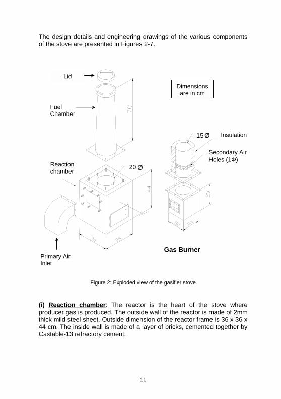
The design details and engineering drawings of the various components of the stove are presented in Figures 2-7.
Figure 2: Exploded view of the gasifier stove
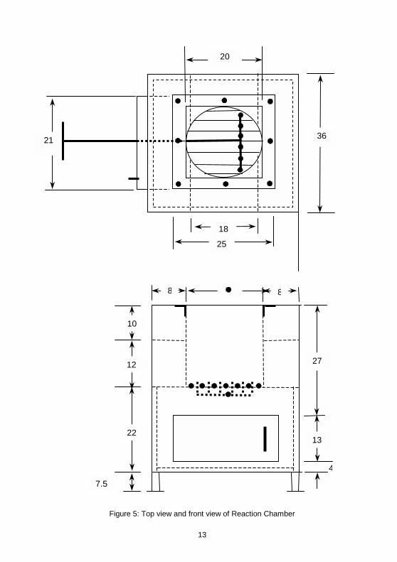
(i) Reaction chamber: The reactor is the heart of the stove where producer gas is produced. The outside wall of the reactor is made of 2mm thick mild steel sheet. Outside dimension of the reactor frame is 36 x 36 x 44 cm. The inside wall is made of a layer of bricks, cemented together by Castable-13 refractory cement.
Primary Air Inlet
15 Ø
Secondary Air Holes (1Φ)
Insulation
Gas Burner
Fuel Chamber
Lid
Reaction chamber
20 Ø
Dimensions are in cm

12
Figure 3: Isometric view of the Reaction Chamber
Figure 4: Sectional view of Reaction Chamber
(Section A-A)
7.5
12
10
Primary Air Inlet
Producer Gas Outlet
Insulation (Castable 13)
Dimensions are in cm
22
10
12
98
Perforated cylinder
Stud, 5/16" dia.
A 20 Ø
A
Ash scraper
Stud, 5/16" dia.
Guide bush 44
Ash pit door
13
Figure 5: Top view and front view of Reaction Chamber
18
36 21
20
25
13
27
4
8 8
10
12
22
7.5
14
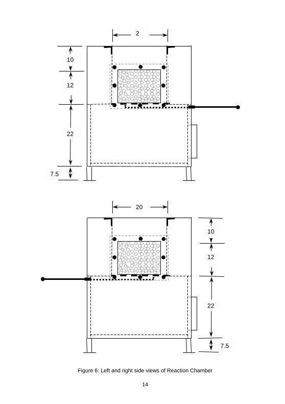
Figure 6: Left and right side views of Reaction Chamber
7.5
22
12
10
20
7.5
22
12
10
2
15
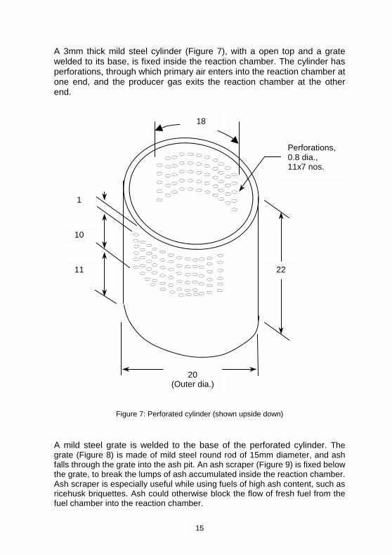
A 3mm thick mild steel cylinder (Figure 7), with a open top and a grate welded to its base, is fixed inside the reaction chamber. The cylinder has perforations, through which primary air enters into the reaction chamber at one end, and the producer gas exits the reaction chamber at the other end.
Figure 7: Perforated cylinder (shown upside down)
A mild steel grate is welded to the base of the perforated cylinder. The grate (Figure 8) is made of mild steel round rod of 15mm diameter, and ash falls through the grate into the ash pit. An ash scraper (Figure 9) is fixed below the grate, to break the lumps of ash accumulated inside the reaction chamber. Ash scraper is especially useful while using fuels of high ash content, such as ricehusk briquettes. Ash could otherwise block the flow of fresh fuel from the fuel chamber into the reaction chamber.
Perforations, 0.8 dia., 11x7 nos.
22
20 (Outer dia.)
18
1
10
11

16
The ash scraper slides through a cylindrical guide bush, which is welded to the body of the reaction chamber. For easy assembling, the slider rod is connected to the ‘fingers’ by a threaded joint. The ash scraper is operated by sliding it in and out horizontally. Its frequency of operation is generally once in 10-20 minutes, depending on the ash content in the fuel.
[Material: Mild Steel round rod, 15mm dia.]
Figure 8: Grate (welded at the base of the perforated cylinder)
[Material: Mild steel round rod, 15mm dia.]
Figure 9: Ash Scraper (with support bush)
4
19.5 Φ (outer)
Guide Bush 1.6 inner dia., 2.4 outer dia.
638
11
15
4
4
Slider rod
Threaded joint
17
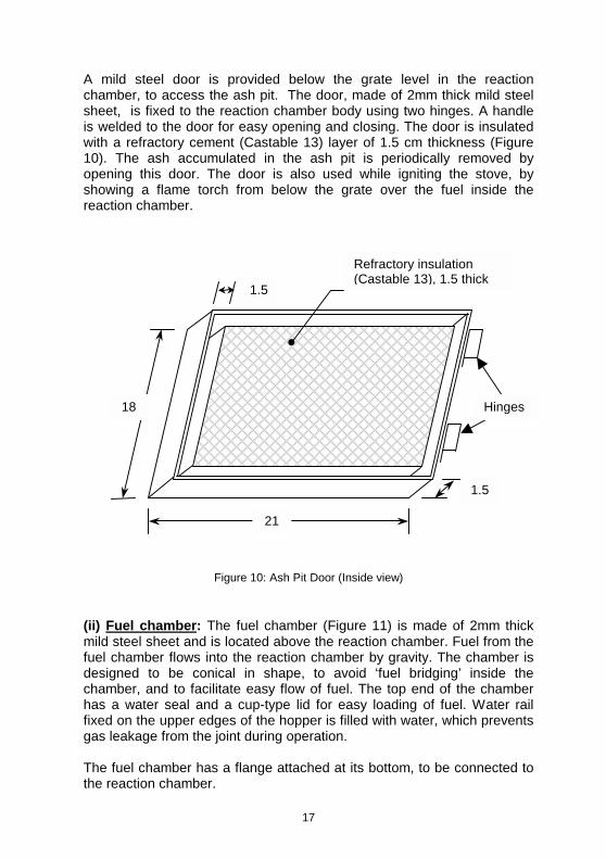
A mild steel door is provided below the grate level in the reaction chamber, to access the ash pit. The door, made of 2mm thick mild steel sheet, is fixed to the reaction chamber body using two hinges. A handle is welded to the door for easy opening and closing. The door is insulated with a refractory cement (Castable 13) layer of 1.5 cm thickness (Figure 10). The ash accumulated in the ash pit is periodically removed by opening this door. The door is also used while igniting the stove, by showing a flame torch from below the grate over the fuel inside the reaction chamber.
Figure 10: Ash Pit Door (Inside view)
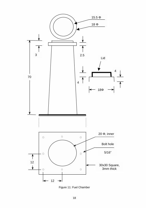
(ii) Fuel chamber: The fuel chamber (Figure 11) is made of 2mm thick mild steel sheet and is located above the reaction chamber. Fuel from the fuel chamber flows into the reaction chamber by gravity. The chamber is designed to be conical in shape, to avoid ‘fuel bridging’ inside the chamber, and to facilitate easy flow of fuel. The top end of the chamber has a water seal and a cup-type lid for easy loading of fuel. Water rail fixed on the upper edges of the hopper is filled with water, which prevents gas leakage from the joint during operation. The fuel chamber has a flange attached at its bottom, to be connected to the reaction chamber.
1.5
21
18
1.5
Hinges
Refractory insulation (Castable 13), 1.5 thick
18
Figure 11: Fuel Chamber
20 Φ, inner
Bolt hole
30x30 Square, 3mm thick
5/16”
12
12
4
4
15.5 Φ
18 Φ
70
2.5 3
18Φ
Lid
19
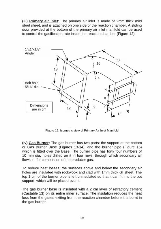
(iii) Primary air inlet: The primary air inlet is made of 2mm thick mild steel sheet, and is attached on one side of the reaction chamber. A sliding door provided at the bottom of the primary air inlet manifold can be used to control the gasification rate inside the reaction chamber (Figure 12).
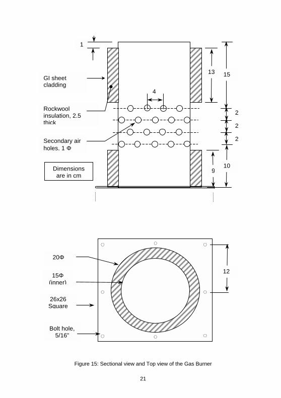
Figure 12: Isometric view of Primary Air Inlet Manifold (iv) Gas Burner: The gas burner has two parts: the support at the bottom or Gas Burner Base (Figures 13-14), and the burner pipe (Figure 15) which is fitted over the Base. The burner pipe has forty four numbers of 10 mm dia. holes drilled on it in four rows, through which secondary air flows in, for combustion of the producer gas. To reduce heat losses, the surfaces above and below the secondary air holes are insulated with rockwook and clad with 1mm thick GI sheet. The top 1 cm of the burner pipe is left uninsulated so that it can fit into the pot support, which will be placed over it. The gas burner base is insulated with a 2 cm layer of refractory cement (Castable 13) on its entire inner surface. The insulation reduces the heat loss from the gases exiting from the reaction chamber before it is burnt in the gas burner.
Dimensions are in cm
16
2
23
12
18
4
4
8
12
4
1"x1”x1/8” Angle
Bolt hole, 5/16" dia.
20
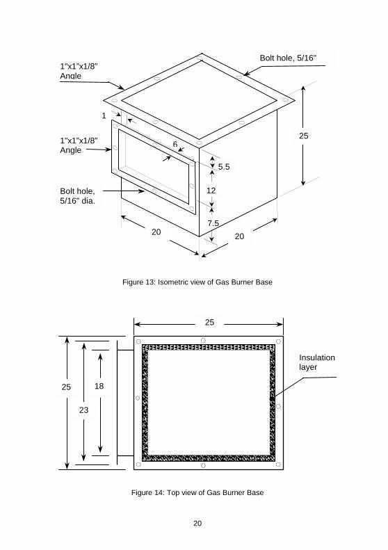
Figure 13: Isometric view of Gas Burner Base
Figure 14: Top view of Gas Burner Base
5.5
6
1
12
7.5
25
20 20
1"x1”x1/8” Angle
Bolt hole, 5/16"
1"x1”x1/8” Angle
Bolt hole, 5/16" dia.
Insulation layer
25
25
18
23
21
Figure 15: Sectional view and Top view of the Gas Burner
13
1
2
2
2
15
10
4
9
Rockwool insulation, 2.5 thick
Secondary air holes, 1 Φ
Dimensions are in cm
GI sheet cladding
15Φ (inner)
26x26 Square
Bolt hole, 5/16”
12
20Φ
22
Asbestos gaskets are used while assembling the individual components together. Three gaskets, of 30x30, 23.5x17.5 and 23x17 square size (outer dimensions), are used for connecting the fuel chamber, primary air inlet and the gas burner respectively, to the reaction chamber. A fourth gasket, of 26x26 square size is used to connect the two parts of the gas burner together. 2.1.2 Pot Support Pot support is designed to hold two pots of 32cm diameter each, with a depth of about 22cm. Hot flue gases from the burner enters the first pot at the bottom of the pot support. The exhaust from the first pot support enters the second pot support at one side and exits through a chimney at the other side. The pot support is made of 2mm thick mild steel sheet and insulated with a 2cm layer of Castable 13 refractory cement. A 110 cm high mild steel chimney is attached at the flue gas exit of the second pot support. To reduce heat losses from the chimney, its outer surface is insulated with a 2.5cm thick slab of fiberglass wool and clad with aluminium sheet. A GI pipe or mild steel ‘L’ angle leg is attached at the bottom of the second pot support for better stability. Design details of pot support are presented in Figure 16.

23
Figure 16: Detailed dimensions of the two-pot configuration (for 32 cm dia. aluminium pots)
15
6 610
5
67
Chimney, 10 x 18
Connector flange 9.5x18 inner
14.5x23 outer
All dimensions are in "cm".
Insulation (Castable 13) 2 cm thick
2
32 32
15.5Φ
110
38
Connector flange 9.5x18 inner
14.5x23 outer
Support leg
24
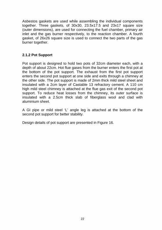
2.2 Construction Photographs
Figure 17: Reaction Chamber with ash scraper
Figure 18: Reaction Chamber (Top view)
25
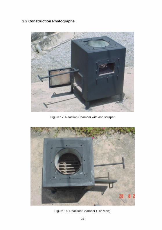
Figure 19: Perforated cylinder without the grate (shown upside down)
Figure 20: Ash Scraper

26
Figure 21: Fuel Chamber without lid
Figure 22: Inlet manifold, with bottom door for controlling primary air inlet
27
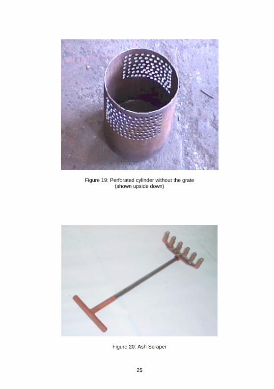
Figure 23: Gas Burner
Figure 24: Gas Burner Base
28
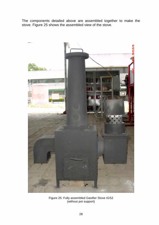
The components detailed above are assembled together to make the stove. Figure 25 shows the assembled view of the stove.
Figure 25: Fully assembled Gasifier Stove IGS2 (without pot support)

29
3. Operational Details 3.1 Fuel Characteristics IGS2 is reasonably versatile in the types of fuels it can handle. Four types of fuels were tested and found to be suitable to be used with the gasifier stove. These include ricehusk and saw dust briquettes, wood chips, wood twigs and coconut shells. The fuel should be sized before loading into the fuel chamber. An average size of 25-50mm is acceptable size for the fuel pieces. Figure 26 illustrates the types of fuels and average size of fuel pieces that can be used in the stove. Average properties of wood chips and ricehusk briquettes are presented in Table 1, for comparison.
Figure 26: Fuels used in the Gasifier Stove
Table 1. Average properties of wood chips and rice husk briquettes
Wood Rice husk
Apparent density, (kg/m³) 784 1006 Bulk density, (kg/m³) 350 620
Ultimate Analysis (dry basis)
Carbon 51.85 41.44
Hydrogen 5.4 4.94
Oxygen 34.64 37.32
Proximate analysis (wet basis) Moisture content, (%) Volatile matter, (%) Fixed carbon, (%) Ash, (%)
7.31
75.07 17.09 0.53
5.93
61.02 16.59 16.46
30
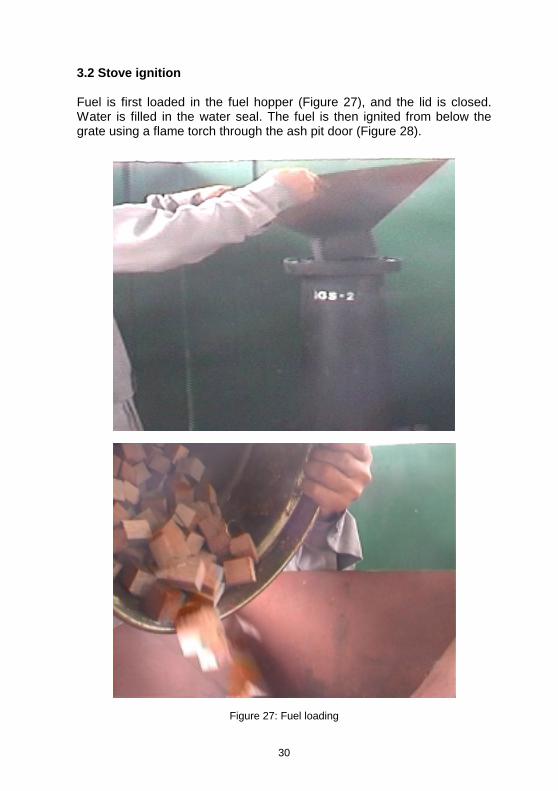
3.2 Stove ignition Fuel is first loaded in the fuel hopper (Figure 27), and the lid is closed. Water is filled in the water seal. The fuel is then ignited from below the grate using a flame torch through the ash pit door (Figure 28).
Figure 27: Fuel loading
31
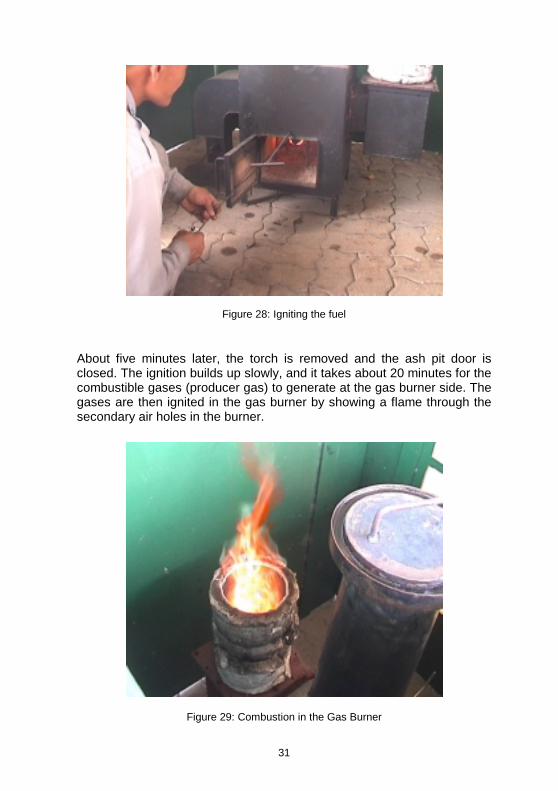
Figure 28: Igniting the fuel
About five minutes later, the torch is removed and the ash pit door is closed. The ignition builds up slowly, and it takes about 20 minutes for the combustible gases (producer gas) to generate at the gas burner side. The gases are then ignited in the gas burner by showing a flame through the secondary air holes in the burner.
Figure 29: Combustion in the Gas Burner
32
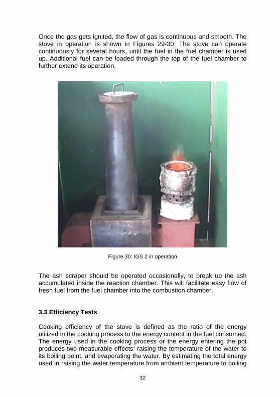
Once the gas gets ignited, the flow of gas is continuous and smooth. The stove in operation is shown in Figures 29-30. The stove can operate continuously for several hours, until the fuel in the fuel chamber is used up. Additional fuel can be loaded through the top of the fuel chamber to further extend its operation.
Figure 30: IGS 2 in operation The ash scraper should be operated occasionally, to break up the ash accumulated inside the reaction chamber. This will facilitate easy flow of fresh fuel from the fuel chamber into the combustion chamber. 3.3 Efficiency Tests Cooking efficiency of the stove is defined as the ratio of the energy utilized in the cooking process to the energy content in the fuel consumed. The energy used in the cooking process or the energy entering the pot produces two measurable effects: raising the temperature of the water to its boiling point, and evaporating the water. By estimating the total energy used in raising the water temperature from ambient temperature to boiling

33
point, and in evaporating a known quantity of water, the cooking efficiency could be determined. The lower calorific value of the fuel is used in the efficiency calculation. By measuring the total quantity of fuel used during the test duration, and using the calorific value, the total energy supplied can be estimated. Wood and rice husk briquettes were used as fuels in this study. Wood cut from eucalyptus logs and sun-dried for days with sizes ranging from 25 to 50 mm, and rice-husk briquettes produced by a heated-die screw-press machine were used as fuel after splitting into small pieces (Figure 31). The properties of wood and briquette-pieces were given earlier in Table 1.
Figure 31: Fuels used in the efficiency tests In the Water Boiling Test, the two-pot configuration, design details of which has been provided in Figure 16, was used. A known quantity of water was taken in both pots, which was then heated on the gasifier stove. The quantity of water evaporated after complete burning of the fuel was then measured to calculate the efficiency. Figure 31 shows the biomass-fired gasifier stove during the water boiling test.

34
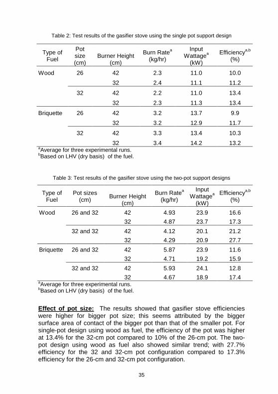
Figure 32: Fully assembled gasifier stove IGS2, with pot support A detailed procedure of the water boiling tests and sample calculations of efficiency using the two-pot configuration is presented in the Appendix at the end. 3.4 Experimental Results A number of experiments were done to investigate the effects of different parameters on the performance of the gasifier stove. Different combinations of fuel, pot size, number of pots and gas burner height were tested. The effects of fuel, pot size and pot support on the cooking efficiency of the gasifier stove were determined and summarized. A summary of the test results is shown in Tables 2 and 3.
35
Table 2: Test results of the gasifier stove using the single pot support design
aAverage for three experimental runs. bBased on LHV (dry basis) of the fuel.
Table 3: Test results of the gasifier stove using the two-pot support designs
Type of Fuel
Pot sizes (cm) Burner Height
(cm)
Burn Ratea (kg/hr)
Input Wattagea
(kW)
Efficiencya,b
(%)
Wood 26 and 32 42 4.93 23.9 16.6 32 4.87 23.7 17.3 32 and 32 42 4.12 20.1 21.2 32 4.29 20.9 27.7 Briquette 26 and 32 42 5.87 23.9 11.6 32 4.71 19.2 15.9
32 and 32 42 5.93 24.1 12.8 32 4.67 18.9 17.4
aAverage for three experimental runs. bBased on LHV (dry basis) of the fuel.
Effect of pot size: The results showed that gasifier stove efficiencies were higher for bigger pot size; this seems attributed by the bigger surface area of contact of the bigger pot than that of the smaller pot. For single-pot design using wood as fuel, the efficiency of the pot was higher at 13.4% for the 32-cm pot compared to 10% of the 26-cm pot. The two-pot design using wood as fuel also showed similar trend; with 27.7% efficiency for the 32 and 32-cm pot configuration compared to 17.3% efficiency for the 26-cm and 32-cm pot configuration.
Type of Fuel
Pot size (cm)
Burner Height (cm)
Burn Ratea (kg/hr)
Input Wattagea
(kW)
Efficiencya,b
(%)
Wood 26 42 2.3 11.0 10.0 32 2.4 11.1 11.2
32 42 2.2 11.0 13.4
32 2.3 11.3 13.4
Briquette 26 42 3.2 13.7 9.9 32 3.2 12.9 11.7
32 42 3.3 13.4 10.3
32 3.4 14.2 13.2

36
Using briquette as fuel, the efficiency of the single pot design was 10.3% with the 32-cm diameter pot which is slightly higher compared to 9.9% for 26-cm pot size. Similar trend was also observed using the two-pot designs where the efficiency of the 32 and 32-cm pot size configuration was 12.8%, which is slightly higher compared to the 32 and 26-cm configuration which offered an efficiency of 11.6%. Effect of type of fuel: It is found that the efficiency of the stove using wood as fuel was higher as compared with using rice husk. As was found out during the experiment, accumulated ash at the reaction chamber was significantly higher in rice husk briquette burning than with wood; this was due to the fact that rice husk briquette fuel has a higher ash content as compared to wood. Another factor that reduces the efficiency of rice husk briquette compared to wood was with the falling ash, some small burning char particle was also with the rice husk ash resulting into higher combustible loss. Efficiency of the gasifier stove with wood as fuel was 24-28% compared to 16-19% efficiency with rice husk briquettes. 3.5 Concluding remarks The improved gasifier stove developed at AIT can be operated continuously with the highest efficiency reported at 24-28% with the two-pot support configuration using wood as fuel. The results indicate that gasifier stove efficiencies were higher for bigger pot size; this seems attributed by the bigger surface area of contact of the bigger pot compared to that of the smaller pot. The height of the gas burner has effects on the efficiency of the gasifier stove; it was observed that shorter gas burner resulted in the flue gas from the reactor not efficiently burned as some smoke emerged from the gas burner. Too high gas burner provides a cleaner combustion but lowered the efficiency of the stove, likely due to increased distance of the pot bottom from the flame. References: 1. Bhattacharya, S.C., Attalage R.A., Augustus Leon M., Amur G.Q., Salam
P.A., and Thanawat C., 1999, Potential of biomass fuel conservation in selected Asian countries. Energy Conversion & Management, Vol. 40, pp. 1141-1162.
2. Kammen, D.M., 1999. http://www.undp.org/seed/energy/policy/ch_5.htm, 12 Dec. 1999.
37
3. Keyun, Deng, 1993, State of the art of the utilization of agricultural residues and other biomass and identification of priority projects in China in Agricultural Biomass for Sustainable Rural Development, ESCAP, Bangkok.
4. Reddy Amulya K.N., 1997, Robert H. Williams, and Thomas B. Johansson, Energy After Rio: Prospects and Challenges, UNDP.
Further readings: 1. Bhattacharya S.C., San Shwe Hla, Augustus Leon M., and Kapila
Weeratunga. An Improved Gasifier Stove for Institutional Cooking. International Conference on Biomass-based Fuels and Cooking Systems (BFCS-2000), Appropriate Rural Technology Institute (ARTI), Pune, India. November 20-24, 2000
2. Bhattacharya S.C., and Augustus Leon M., ‘A Biomass-fired Gasifier Stove (IGS-2) for Institutional Cooking’, GLOW, A monthly journal published by the Asia Regional Cookstove Program (ARECOP), Yogyakarta, Indonesia, May 2001.

38
Appendix: Water Boling Test The stove efficiency can be calculated using the following formula:
where: mw,i = mass of water initially in cooking vessel, kg
Cpw = specific heat of water, kJ/kg oC mw,evap = mass of water evaporated, kg mf = mass of fuel burned, kg Te = temperature of boiling water, oC Ti = initial temperature of water in pot, oC Hl = latent heat of evaporation at 100 oC and 105 Pa, kJ/kg Hf = calorific value of fuel, kJ/kg Instruments and Equipment:
i. Two aluminium pots without lid ii. Temperature sensors for measuring the ambient and
boiling water temperature iii. A digital balance for measuring the weight of fuel, water
and pot.
Procedure: Both empty pots were weighed separately and the values recorded. The pots were then partially filled with water and weighed again. The initial temperature of the water was also recorded. The gasifier stove was then ignited and the water in both pots was left to boil and evaporate. After complete burning of the whole fuel supplied, both pots were weighted again and the amounts of water evaporated in each pot were recorded.
( )ff
levapwiepwwi
HmHmTTCm
n ,+−=
39
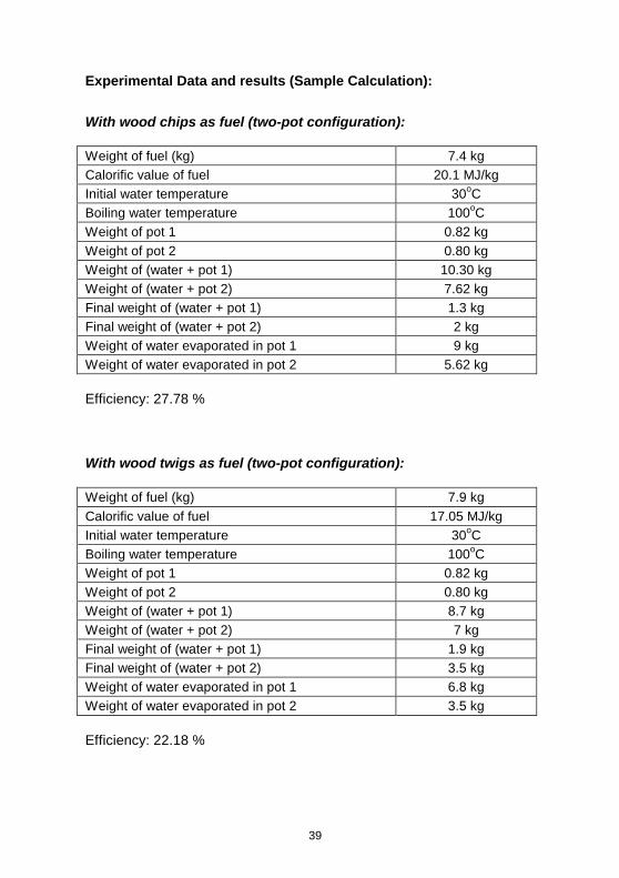
Experimental Data and results (Sample Calculation):
With wood chips as fuel (two-pot configuration): Weight of fuel (kg) 7.4 kg Calorific value of fuel 20.1 MJ/kg Initial water temperature 30oC Boiling water temperature 100oC Weight of pot 1 0.82 kg Weight of pot 2 0.80 kg Weight of (water + pot 1) 10.30 kg Weight of (water + pot 2) 7.62 kg Final weight of (water + pot 1) 1.3 kg Final weight of (water + pot 2) 2 kg Weight of water evaporated in pot 1 9 kg Weight of water evaporated in pot 2 5.62 kg
Efficiency: 27.78 % With wood twigs as fuel (two-pot configuration): Weight of fuel (kg) 7.9 kg Calorific value of fuel 17.05 MJ/kg Initial water temperature 30oC Boiling water temperature 100oC Weight of pot 1 0.82 kg Weight of pot 2 0.80 kg Weight of (water + pot 1) 8.7 kg Weight of (water + pot 2) 7 kg Final weight of (water + pot 1) 1.9 kg Final weight of (water + pot 2) 3.5 kg Weight of water evaporated in pot 1 6.8 kg Weight of water evaporated in pot 2 3.5 kg
Efficiency: 22.18 %
40
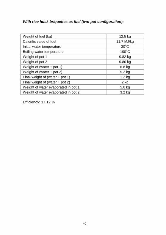
With rice husk briquettes as fuel (two-pot configuration): Weight of fuel (kg) 12.5 kg Calorific value of fuel 11.7 MJ/kg Initial water temperature 30oC Boiling water temperature 100oC Weight of pot 1 0.82 kg Weight of pot 2 0.80 kg Weight of (water + pot 1) 6.8 kg Weight of (water + pot 2) 5.2 kg Final weight of (water + pot 1) 1.2 kg Final weight of (water + pot 2) 2 kg Weight of water evaporated in pot 1 5.6 kg Weight of water evaporated in pot 2 3.2 kg
Efficiency: 17.12 %

41

42

43

44