design and development of wind mill operated water pump
TRANSCRIPT
VISVESVARAYA TECHNOLOGICAL UNIVERSITY, BELAGAVI
KARNATAKA - 590018
PROJECT WORK REPORT ON
“DESIGN AND DEVELOPMENT OF WIND MILL OPERATED
WATER PUMP”
(Sponsored by Karnataka State Council for Science and Technology)
Submitted in the partial fulfilment of the requirement for the award of
BACHELOR OF ENGINEERING DEGREE
IN
MECHANICAL ENGINEERING
submitted by
AKSHATH KUMAR 4DM13ME011
HARISH DV 4DM13ME030
KAVINRAJ 4DM13ME046
MANJUNATHA J 4DM13ME051
Under The Guidance of
Prof. Vani R
Assistant Professor Department of Mechanical Engineering
YIT, Moodbidri.
DEPARTMENT OF MECHANICAL ENGINEERING
YENEPOYA INSTITUTE OF TECHNOLOGY
MOODBIDRI - 574225
2016-2017
YENEPOYA INSTITUTE OF TECHNOLOGY MOODBIDRI - 574225
DEPARTMENT OF MECHANICAL ENGINEERING
CERTIFICATE
This is to certify that the project work entitled “DESIGN AND DEVELOPMENT
OF WIND MILL OPERATED WATER PUMP” is a bonafide work carried out by AKSHATH
KUMAR (4DM13ME011), HARISH DV (4DM13ME030), KAVINRAJ (4DM13ME046),
MANJUNATHA J (4DM13ME051) in partial fulfilment for the award of Bachelor of
Engineering Degree in Mechanical Engineering by the Visvesvaraya Technological University,
Belagavi during the academic year 2016 – 2017. It is certified that all corrections/suggestions
indicated for internal assessment have been incorporated in the report deposited in the department
library. The project report has been approved as it satisfies the academic requirements in respect
with the project work prescribed for the said Degree.
Prof. Vani R Project Guide
Dr. Sathisha N Dr. R. G. D’Souza
Professor and Head of the Department Principal
Dept. of Mechanical Engg. YIT, Moodbidri.
YIT, Moodbidri.
EXAMINERS
DATE: 1………………………………………………………….
PLACE: Moodbidri
2………………………………………………………….
ACKNOWLEDGEMENT
Successful completion of any work would be incomplete without mentioning the people
who made it possible. We are extending our gratitude to all the people who supported us during
the project.
First and foremost, We would like to express our deepest thanks to our project guide
Prof. Vani R, Asst. Professor, Dept. of Mechanical Engineering, for her constant support and
encouragement and providing with necessary facilities. We are highly indebted to her for taking
keen interest in our work, monitoring and providing guidance throughout the course.
We thank Prof. Vani R and Prof. Sushilendra R M, Asst. Professor, Dept. of
Mechanical Engineering, who are the project coordinators, for all their support and
encouragement.
We thank Dr. Sathisha N, Professor & HOD, Dept. of Mechanical Engineering, for all
his suggestions and timely guidance.
We also thank our beloved principal Dr. R.G. D’Souza and the Management and
Trustees of Islamic Academy of Education for their constant support.
Finally we thank all the people who have directly or indirectly helped us throughout the
course of our Project.

ABSTRACT The imminent exhaustion of fossil energy sources spreading global warming, expanding
greenhouse effect, higher need of energy, less availability of power supplies motivates us to use
renewable source of energy like wind-energy. Small wind turbines need to be cost effective, loyal,
affordable minimum maintenance cost for any average person. The aim of this project was to
design and construct a wind pump that is able to provide water to a rural third world village. The
overall design goals of this project focused on affordability and simplicity of design rather than
efficiency. The objectives were achieved using a VAWT turbine connected to a piston pump in
order to create a system that was robust and easy to construct in a low-technology. With certain
modifications, this wind pump would be a cost-effective, low technology method of pumping
clean water.

TABLE OF CONTENTS Chapter
No.
Title Page
No.
ACKNOLEDGEMENT i
ABSTRACT ii
TABLE OF CONTENTS iii
LIST OF FIGURES vi
1 INTRODUCTION 1
1.1 Objectives 2
1.2 Organization of the report 3
2 LITERATURE REVIEW 4
2.1 Main sources of Energy 4
2.1.1 Conventional energy source 4
2.1.2 Non conventional Energy source 5
2.2 Wind energy 6
2.2.1 Advantages of wind Energy 6
2.2.2 Disadvantages of Wind Energy 6
2.2.3 Problems associated with utilizing wind energy 6
2.3 Storage of Wind Energy 7
2.4 Wind Turbine 7
2.4.1 Horizontal axis wind turbine 8
2.4.2 Vertical axis wind turbine 9
2.4.3 Advantages of VAWT over HAWT 11
2.5 Sizing of Rotor 12
2.6 Characteristics & Specifications of Wind Turbine 13
2.6.1 Wind speed 13
2.6.2 Blade Length 13
2.6.3 Blade Height 13
2.6.4 Base Design 14
2.6.5 Tip speed ratio 14
2.7 Site Selection consideration 14
2.7.1 High annual average wind speed 14
2.7.2 Availability of wind curve at the proposed site 14
2.7.3 Wind structures at proposed site 15
2.7.4 Altitude of the proposed site 15
2.7.5 Local ecology 15
2.7.6 Distance to roads or railway 15
2.7.7 Nearness of site to local centre/users 15
2.7.8 Nature of ground 15
2.7.9 Favorable land cost 15
2.8 Wind pump types 15
2.8.1 Multi-bladed wind pump 16
2.8.2 Tjasker wind pump 16
2.8.3 Thai wind pumps 17
2.9 Benefits of Wind pumps 18
2.10 Water Pump 18
2.10.1 Reciprocating Pump 18
2.10.2 Rotary Pump 19
2.10.3 Diaphragm Pump 19
2.10.4 Displacement Type 20
2.10.5 Piston Pump 20
2.11 Slider Crank Mechanism 21
2.12 Summary of the papers reviewed 23
3 METHODOLOGY 27
3.1 Analytical Study 27
3.2 Design of small wind turbine blades 27
3.2.1 Design of Blade, Power output of turbine and pump 28
3.3 Material used for turbine and pump 30
3.3.1 Aluminum sheet and Aluminum Strips 30
3.3.2 Mild steel Rod and Mild steel Strips 31
3.3.3 Flange bearings 31
3.3.4 Bevel gears 32
3.3.5 uPVC pipes 32
3.3.6 Non return valves and bushes 33
3.3.7 Miscellaneous elements 33
3.4 Fabrication of wind turbine 33
3.5 Project setup 34
3.5.1 Different Views of Wind mill Operated Water Pump 34
3.6 Experimentation with wind turbines 36
3.6.1 Working of wind pump 38

3.7 Cost Analysis 38
4 CONCLUSION 39
REFERENCE 40
LIST OF FIGURES Figure
No.
Title Page
No.
2.1 Conventional energy sources 4
2.2 Non conventional Energy 5
2.3 Two examples of horizontal axis wind turbines 8
2.4 An example of a Vertical axis wind turbine 10
2.5 Multi-blade wind pump 16
2.6 Multi-blade Tjasker wind pump 17
2.7 Thai wind pumps 17
2.8 Rotary pump 19
2.9 Displacement pump 20
2.10 Piston pump 21
2.11 Slider crank mechanism 22
3.1 Design Steps 28
3.2 Blade and Strip 30
3.3 Mild steel Strip and rod 31
3.4 Flange bearing 31
3.5 Bevel gears 32
3.6 uPVC pipes 32
3.7 Non return valves 33
3.8 3D model of the work 34
3.9 2D front view 35
3.10 2D top view 35
3.11 Model of wind operated water pump 36
3.12 Working Procedure 37

LIST OF TABLES Table No Title Page
No. 3.1 Wind Velocity v/s day table 37
3.2 Cost Analysis 38
Chapter 1
INTRODUCTION The Imminent exhaustion of fossil energy sources, spreading global warming, expanding
greenhouse effect, higher need of energy, less availability of power supplies motivates us to use
renewable source of energy like wind-energy which is most prominent for our suitable
application. With the rise in understanding of global warming due to Carbon Dioxide produced
by burning of fuels, the use of natural energy resource is coming into picture. Now a day people
are started using of natural sources like wind, hydro, solar energy to produce electricity and
providing power to the various power-plants.
The contribution of these sources in the total consumption of energy in the world is about
15%.The scope for application of air energy now stands inherently enhanced through intensive
research and development carried out all over the world. The exact origin of the first use of wind
power is unknown; however, one of the earliest known uses dates as far back as 3500 B.C. to
drive sailboats using aerodynamic lift (Ages).
Many developing nations are without feasible methods of obtaining clean, drinkable water.
Obtaining water requires walking long distances or crossing through dangerous territory, and this
water is often riddled with disease. One newer method to deliver water is by use of wind power to
pump ground water to the surface. Both the wind turbine and well can be placed in or near
villages to help residents easily acquire clean water without of community member assistance.
In physics, Energy is properties of objects, which is transferable among them via
fundamental interactions, which can be converted in form but not created or destroyed. The energy
of a body is its capacity to do work. It is measured the total amount of work that the body can do.
Energy is the primary and most universal measure of all kinds of work by human beings and
nature. Everything what happens the world is the expression of flow of energy is one of its forms.
The kinetic energy in the wind thus depends on the density of the air i.e. its mass per unit of
volume. In other words, the “heavier” the air, the more energy is received by the wind turbine.
There have been many improvements to the windmill over the years. Windmills have been
equipped with air breaks, to control speed in strong winds. Some vertical axis windmills have even
been equipped with hinged blades to avoid the stresses at high wind speed. Some windmills, like
the cyclo-turbine have been equipped with a vane that senses wind direction and causes the rotor
to rotate into the wind. Wind turbine generations have been equipped with gearboxes to control
speeds. Wind turbines have also been equipped with generators which coverts shaft power into
electrical power. Many of the sails on windmills have also been replaced with propeller-like
airfoils. Some windmills can also stall in the wind control wind speed.
However, due to limited availability of power supplies or resources some alternate form of
energy has to be used to supply water from the source to a point of consumption. Wind energy is
an important source of renewable energy that can be used for pumping water in remote locations.
A wind pump is nothing but a windmill used for pumping water, either as a source of fresh water
or wells. It is one of the earliest methods of utilizing the energy of the wind to pump water.
1.1 Objectives
To focus on energy generation where it is most needed, by designing a vertical axis wind
mill. Wind turbines are a form of renewable energy that will help the environment by not
producing emissions while creating electricity or mechanical energy.
The vertical turbine has the advantage even in urban or other crowded zones, whereas
horizontal axis turbines require a large footprint due to the space needed for safe spinning
of the blades. Vertical axis wind turbines are generally gaining popularity for residences
urban settings because they can be placed lower to the ground and on rooftops.
To design a small scale helical wind turbine and to see the feasibility of it. The main
advantage of helical wind turbine design is, it rotates in minimum wind speeds also.
With helical wind turbine, bird issue have rarely been a concern. Helical wind turbines are
also less susceptible to problems with crosswinds than bladed turbines.
To design and develop helical wind mill operated water pump which will cope up with
ordinary pump.
1.2 Organization of the Report
Chapter 1- Introduction
It includes the general introduction to project, objectives and organization of the report.
Chapter 2- Literature review
The thorough literature survey carried out is presented in this chapter. It comprises of
introduction to energy, classification, Wind Turbine, Sizing of rotor, wind pump types, slider
crank mechanism and the summary of the journal papers reviewed.
Chapter 3- Methodology
It focuses on fabrication of wind turbine, testing of wind turbine and working of turbine to
pump water.
Chapter 4- Conclusion
This chapter lists the important results of the present work. Also several suggestions are made
for the improvement of the work and future directions.
Chapter 2
LITERUTURE REVIEW
In physics, energy is properties of objects, which is transferable among them via
fundamental interactions, which can be converted inform but not created or destroyed. The Joule
is the SI unit of energy, based on the amount of transferred to an object by the mechanical of
moving it 1 meter against a force of 1 Newton. The energy of a body is its capacity to do work. It
is measured the total amount of work that the body can do. Energy is the primary and most
universal measure of all kinds of work by human beings and nature. Everything what happens the
world is the expression of flow of energy is one of its forms.
2.1 Main sources of energy
Conventional energy source
Non-conventional energy source
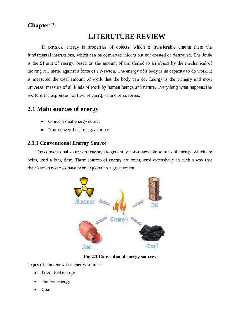
2.1.1 Conventional Energy Source
The conventional sources of energy are generally non-renewable sources of energy, which are
being used a long time. These sources of energy are being used extensively in such a way that
their known reserves have been depleted to a great extent.
Fig 2.1 Conventional energy sources
Types of non renewable energy sources
Fossil fuel energy
Nuclear energy
Coal

2.1.2 Non-conventional source
Energy generated by using wind, tides, solar, geothermal heat and biomass including farm and
animal waste as well as human excreta is known as non-conventional energy. All these sources are
renewable or inexhaustible and do not cause environmental pollution. More over them do not
require heavy expenditure.
Some of these sources are:
Wind energy
Tidal energy
Solar energy
Geothermal energy
Biomass
Fig 2.2 Non conventional Energy
2.2 Wind Energy
Wind energy originates from solar energy where the sun heats the atmosphere unevenly
causing some parts to be warmed than others. The warmer patches of air rise and other air patches
blow in to replace them. Thus alternating air flow which results in wind. Winds are caused by two
factors. The absorption of solar energy on the earth's surface and in the atmosphere. The rotation
of earth about its axis and its motion around the sun. A wind mill converts the kinetic energy of
moving air into mechanical energy that can be either used to run the machine or to run the
generator to produce electricity. Because of these factors, alternate heating and cooling cycles
occur, differences in pressure are obtained, and the air is caused to move.

2.2.1 Advantages of wind Energy
It is the cheapest source of energy. This is because it does not require importation and it is
readily available.
Wind power has the potential to reduce the amount of carbon dioxide and related greenhouse
gases that contribute to global warming.
Require less labour expenses as maintenance is very minimal and few personnel are
required at the site.
2.2.2 Disadvantages of Wind Energy
Varying wind speeds and directions make it difficult to use wind as a consistent source of
power.
Initial investment on construction and installation of wind power machinery is very
Costly.[1- 2]
2.2.3 Problems associated with utilizing Wind energy
The energy is available in dilute form, because of this conversion machines have to be
necessarily large.
The availability of the energy varies considerably over a day and with the seasons. For this
reason some means of storage have to be devised if a continuous supply of power is
required.
2.3 Storage of Wind Energy
A good system of energy storage is especially important where wind energy is concerned.
Because of the strongly fluctuating supply of wind (and therefore the output of the windmill),
storage is necessary to meet the demands.
Some means of wind energy storage are:
Batteries: The lead (-acid) and the nickel/cadmium batteries are often used in combination
with small wind - driven generators
Electrolysis of water into hydrogen and oxygen used with wind-driven generators: The
hydrogen is stored in a tank and can be used for heating or as fuel for a motor at any
chosen moment. This method is expensive and energy-inefficient.
Pumped-up water in a reservoir: Usually in combination with water-pumping windmills.
Flywheels: This is a seldom-practiced method because of the needed 'high technology'.
This method is not very suitable for Third World countries.
Contribution to electricity supply. Power generated could be harnessed and channeled to
the public electricity supply system. [2]
2.4 Wind turbine
Wind turbine is a device that converts the kinetic energy from the wind into mechanical
energy. The use of wind mills is one of the most popular methods of using the energy from natural
sources. A small scale wind mills can be used to power small home appliances by decreasing the
electricity cost and quantity of fuel burnt to produce equal amount of electricity. A typical system
in a disclosed site could easily generate more power than household lamps and other use of
electrical appliances. If mechanical energy is used to produce electricity, the device is called a
wind generator. If the mechanical energy is used to drive the machinery, such as for grinding gain
or pumping water the device is called wind mill or wind pump.
Wind turbines are classified into two general type Horizontal axis wind Turbine and
Vertical axis wind turbine. A horizontal axis machine has its blades rotating on an axis parallel
to ground. A vertical axis machine has its blades rotating on an axis perpendicular to the ground.
There are number of available designs for both and each type has certain advantages and
disadvantages.
2.4.1 Horizontal axis wind turbine
This is the most common wind turbine design. In addition to being parallel to the ground,
the axis of blade rotation is parallel to the wind flow. Some machines are designed to operate in an
upwind mode, with the blades upwind of the tower. In this case, a tail vane is usually used to keep
the blades facing into the wind. Other designs operate in a downward mode so that the wind
passes the tower before striking the blades. Without a tail vane, the machine rotor naturally tracks
the wind in a downward mode. Some very large wind turbines use a motor-driven mechanism that
turns the machine in response to a wind direction sensor mounted on the tower.
Different types of HAW are
Single bladed
Double bladed
Multi bladed
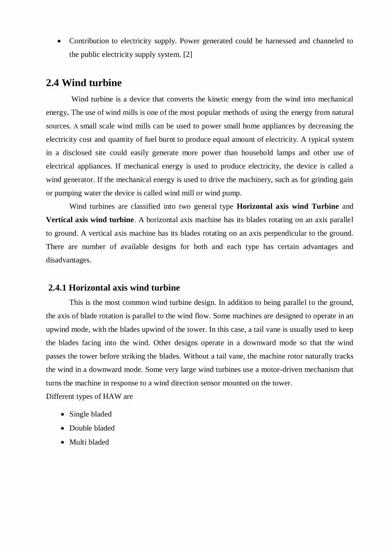
Fig 2.3 Two examples of horizontal axis wind turbines
In this Horizontal axis wind turbines most common type wind turbine used is multi bladed
type in which more number of turbine blades are connected to rigid hub and it has a more power
coefficient, high starting torque and added advantage of simplicity.
Advantages of HAWT:
• Variable blade pitch which gives the blades of turbines the optimum attack angle. Allowing the
attack angle to be adjusted gives greater control, so that turbine can stores the maximum amount
of wind energy for the day and season time.
• High efficiency, since the turbine blades always move perpendicularly to the wind, collecting
power through the whole rotation.
• The taller tower base provides access to stronger wind in sites with wind shear.
2.4.2 Vertical axis wind turbine
Although vertical axis wind turbines have existed for centuries, they are not as common as
their horizontal counterparts. The main reason for this is that they do not take advantage of the
higher wind speeds at higher elevations above the ground as well as horizontal axis turbines. The
basic vertical axis design are the Darrieus, which has curved blades and efficiency of 35%, the
Giromill, which has straight blades, and efficiency 35%, and the Savonius, which uses scoops to
catch the wind and the efficiency of 30%. a vertical axis machine need not be oriented with
respect to wind direction. Because the shaft is vertical, the transmission and generator can be
mounted at ground level allowing easier servicing and lighter weight, lower cost tower. They
usually operate closer to the ground which has an advantage of allowing for placement or
replacement of heavy equipment. The procedure for other turbines especially lift type turbines was
too expensive and hence this led us to choose the drag type wind turbines with less complexities
involved in construction.

There are mainly two types of VAWT namely:
Darrieus rotor
Savonius rotor
Fig 2.4 An example of a Vertical axis wind turbine
Darrieus rotor
It uses blades similar to those used in the horizontal axis wind turbine (HAWT). It has two
or more curved blades that depend on wind in order to revolve around a central column. It
functions by generating a lift using the rotating motion of the blades. The wind acting on the blade
creates a rearward momentum change which propels the blade in the direction of rotation. This
cannot occur unless the blades are already rotating and therefore they require a separate means of
starting i.e. they are not self-starting.
Savonius rotor
It operates like a water wheel which uses drag forces. It has a simple design and is
therefore relatively simple and cheaper to build. It is mostly used in situations that do not require
large amounts of power. However, it is less powerful than most HAWT because it uses drag to
rotate itself and has a higher power to weight ratio. The total amount of turning torque of the
mechanism relies on the drag force on each blade.
Advantages of VAWT:
They are always facing the wind hence no need to escort for the wind.
Have greater surface area for energy storage hence can store more energy.
Are more efficient in stormy or breezy winds.
Can be installed in locations like on roofs, along highways, in parking lots.
Can be scaled more easily from mill watts to megawatts.
Can be significantly less expensive to produce as they are inherently simpler.
Can have low maintenance downtime as mechanisms are at or near ground level.
Produce less noise due to low speed hence less noise.
In this project the selected wind turbine is Vertical axis wind turbines, (VAWTS) have the
main rotor shaft arranged vertically. One advantage of this arrangement is that the turbine does not
need to be pointed into the wind to be effective, which is an advantage on a site where the wind
direction is highly variable for example when the turbine is integrated into a building. Also, the
generator and gearbox can be placed near the ground, using the drive from the rotor assembly to
the ground based gearbox, improving accessibility for maintenance. Typically, helical wind
turbines are designed along a vertical axis.
2.4.3 Advantages of VAWT over HAWT
They are mounted lower to the ground making it easy for maintenance if needed.
They start creating power at a minimum speed of air.
They may be able to be built at locations where taller structures, such as the horizontal
type, can’t be.
Higher power utilization – 20% higher than HAWT.
Lower noise level only 27-37DB, suitable for your living condition.
Safer operation- Spin at slower speeds than horizontal turbines, decreasing the risk of
injuring birds and also decreasing noise level.
Simpler installation and maintenance – besides the traditional installation site, it can be
mounted directly on a rooftops, doing away with the tower and associated guy lines.
Not affected by orientation variation – no matter the wind blow from any orientation,
VAWT can work without regard to its face [3].
2.5 Sizing of Rotor
The power of the wind is proportional to air density, area of the segment of wind being
considered, the natural wind speed. The relationships between all the above variables are given in
equation (1)
Pw = ½ ρAu3………... (1)
Where,
Pw: power of the wind (W)
M: air density (kg/m3)
A: area of a segment of the wind being considered (m2)
u: undisturbed wind speed (m/s)
At standard pressure and temperature (STP = 273K and 101.3 KPa),
Equation (1) reduces to:
Pw =0.647ρAu3…………. (2)
A turbine cannot extract or take 100% of the winds energy because some of the winds energy
used in pressure changes occurring across the blades of turbines. This pressure change causes
velocity to decrease and therefore usable energy.
The mechanical power which could be obtained from the wind with an ideal turbine is
given as:
Pm = ½ M(16/27 Au3) ……………… (3)
Where,
Pm: mechanical power (W)
A: swept area of a turbine
16/27: Betz coefficient The Betz coefficient gives idea that 59.3% of the power in the
wind can be obtained in the case of an ideal turbine.
For a VAWT, This area depends on both the diameter and blade length of turbine.
Swept area is: As = Dt lb …………………. (4)
Where,
As: swept area (m2)
Dt: diameter of the turbine (m)
lb: length of the turbine Blades (m)
Efficiency of turbines lies in the range of 35-40% is very good, and occurs only in case for
large-scale turbines. It is important to note that the pressure drop across the turbine blades
is very small, around 0.02% of the ambient air pressure.
So, Equation (3) can be re-written as
Pm = CpPw ……………….. (5)
The coefficient of performance depends on speed of wind, rotational speed of the turbine and
blade parameters such as pitch angle and angle of attack.
2.6 Characteristics & Specifications of Wind Turbine
2.6.1 Wind Speed
This is very important to the productivity of a windmill. The wind turbines generate power
with the wind. The wind rotates the axis (horizontal or vertical) and causes the shaft on the
generator to sweep past the magnetic coils creating an electric current.
2.6.2 Blade Length
This is important because the length of the blade is directly proportional to the swept area.
Larger blades have a greater swept area and thus catch more wind with each revolution. Because
of this, they may have higher torque.
2.6.3 Base Height
The height of the base affects the windmill immensely. The higher a windmill is, the more
productive it will be due to the fact that as altitude increases so does the wind speeds.
2.6.4 Base Design
Some base is stronger than others. Base is important in construction of the windmill
because not only do they have to support the windmill, but they must also be subjected to their
own weight and the drag of the wind. If a weak tower is subjected to these elements, then it will
surely collapse. Therefore, base must be identical so as to ensure a fair comparison.
2.6.5 Tip Speed Ratio
The tip speed ratio is very important. The tip speed ratio is proportional to the windmill's
productivity. It is how many times blades rotate greater than the wind speed.
2.7 Site Selection Consideration
The power available in the wind increases rapidly with the speed; hence wind energy
conversion machines should be located preferable in areas where the winds are strong and
persistent. The following point should be considered while selecting site for wind energy
conversion system.
2.7.1 High annual average wind speed
The wind velocity is the critical parameter. The power in the wind Pw, through a given X-
section area for a uniform wind velocity is Pw= KV³ (K is constant). It is evident, because of the

cubic dependence on wind velocity that small increase in V markedly affect the power in the wind,
e.g. doubling V, increases Pw by a factor of 8.
2.7.2 Availability of wind curve at the proposed site
This important curve determines the maximum energy in the wind and hence is the
principle initially controlling factor in predicting the electrical o/p and hence revenue return of the
WECS machines, it is desirable to have average wind speed V such that V>=12-16 km/hr (3.5- 4.5
m/s).
2.7.3 Wind structures at proposed site
Wind especially near the ground is turbulent and gusty & changes rapidly in direction and
in velocity. This departure from homogeneous flow is collectively referred to as “the structure of
the wind”.
2.7.4 Altitude of the proposed site
It affects the air density and thus power in the wind & hence the useful WECS electric
power output. The wind tends to have higher velocities at higher altitudes.
2.7.5 Local ecology
If the surface is bare rock it may mean lower hub heights hence lower structure cost, if
trees or glass or venations are present. All of which tends to restructure the wind.
2.7.6 Distance to roads or railway
This is another factor the system engineer must consider for heavy, machinery, structures,
materials, blades and other apparatus have to move into chosen WECS site.
2.7.7 Nearness of site to local centre/users
This obvious criterion minimizes transmission line length and losses and cost.
2.7.8 Nature of ground
Ground condition should be such that the foundations for WECS are secured, ground
surface should be stable.
2.7.9 Favorable land cost
Land cost should be favorable as this along with sitting costs, enters into the total
WECS system cost. [3]
2.8 Wind Pump Types
Three types of wind turbines used in pumping water and for irrigation purposes are multi-
blade wind pump, the Tjasker and Thai wind pumps.
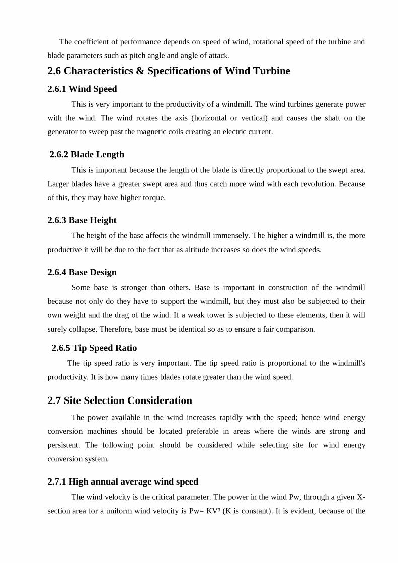
2.8.1 Multi-bladed wind pump
"American" multi-bladed wind pumps can be found worldwide and are manufactured in
the United States, Argentina, China, New Zealand, and South Africa. A 16 ft (4.8 m) diameter
wind pump can lift up to 1600 US gallons (about 6.4 metric tons) of water per hour to an elevation
of 100 ft with a 15 to 20 mph wind (24–32 km/h). The Aermotor Windmill Company,
manufacturer of the wind powered water pumps, is one of the oldest manufacturers American. A
properly designed Wind pump begins working in a 3-4 mph (5 to 6.5 km/h) wind. Wind pumps
require little maintenance - only a change of gear box oil is required annually. An estimated
60,000 wind pumps are still in use in the United States. They are particularly attractive for use at
remote sites where electric power is not available and maintenance is difficult to provide.
Fig 2.5 Multi-blade wind pump
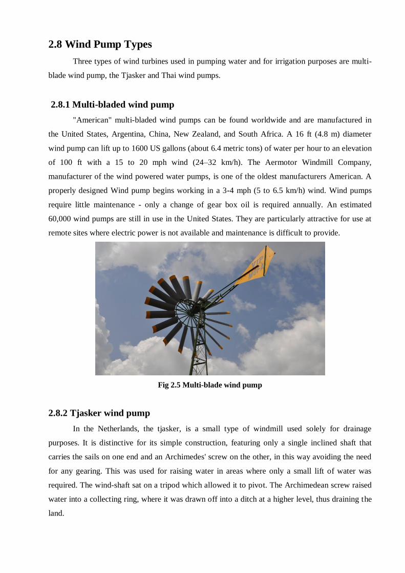
2.8.2 Tjasker wind pump
In the Netherlands, the tjasker, is a small type of windmill used solely for drainage
purposes. It is distinctive for its simple construction, featuring only a single inclined shaft that
carries the sails on one end and an Archimedes' screw on the other, in this way avoiding the need
for any gearing. This was used for raising water in areas where only a small lift of water was
required. The wind-shaft sat on a tripod which allowed it to pivot. The Archimedean screw raised
water into a collecting ring, where it was drawn off into a ditch at a higher level, thus draining the
land.
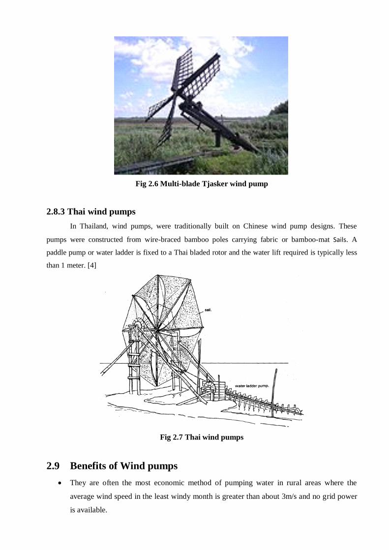
Fig 2.6 Multi-blade Tjasker wind pump
2.8.3 Thai wind pumps
In Thailand, wind pumps, were traditionally built on Chinese wind pump designs. These
pumps were constructed from wire-braced bamboo poles carrying fabric or bamboo-mat Sails. A
paddle pump or water ladder is fixed to a Thai bladed rotor and the water lift required is typically less
than 1 meter. [4]
Fig 2.7 Thai wind pumps
2.9 Benefits of Wind pumps
They are often the most economic method of pumping water in rural areas where the
average wind speed in the least windy month is greater than about 3m/s and no grid power
is available.
They have no fuel requirements, contrary to engine-driven pumps which require expensive
fuel that is difficult to obtain in rural areas.
They represent an environmentally sound technology, though there is some noise and
visual impact.
They are highly reliable if given regular maintenance, and are also less vulnerable to theft
or damage than other systems.
They can last a long time, typically 20 years for a well-made, regularly maintained
machine.
They can be locally manufactured in most developing countries, creating indigenous skills
and reducing foreign exchange requirements for costly diesel fuel engines.
2.10 Water Pump
Water is The Most Common Fluid handled by pump. Virtually therefore all types of
pumps may be considered as potentially suitable for water lifting. However, pumps used wind-
powered pumping systems are generally found to be of three types reciprocating, rotary,
displacement type. A positive displacement type pump is that is which a measured quantity of
water is entrapped in a space its pressure is raised and then it is delivered.
2.10.1 Reciprocating Pump
In order to start reciprocating pump is reasonably low wind speed. It is necessary to obtain
sufficient starting torque which is possible by using high rotor solidity. Hence many windmills
have a large number of vanes or sails to providing high starting torque. All types of reciprocating
pumps are self-priming in that they do not need to be filled with fluid before pumping. Its
diameter and the length of the pumping stroke inside it are majors in determining the windmill’s
pumping capacity. The stroke of a windmill is the distance which the plunger moves up and down.
A short stroke enables the mill to begin pumping in a light breeze but in strong breeze a long
stroke causes more water to be pumped.
2.10.2 Rotary Pump
This is commonly used in China and South-east Asia for a head up to 3m and consists of
rectangular wooden pallets or paddles mounted on a continuous wooden chain that runs up an
inclined square section open wooden trough. The paddles and chain pass around a large wood
at the base of a trough which is submerged in water. This type of pump is commonly used with
Chinese vertical-axis wind pump systems and Thai high-speed wooden rotors and Thai sail
rotors.
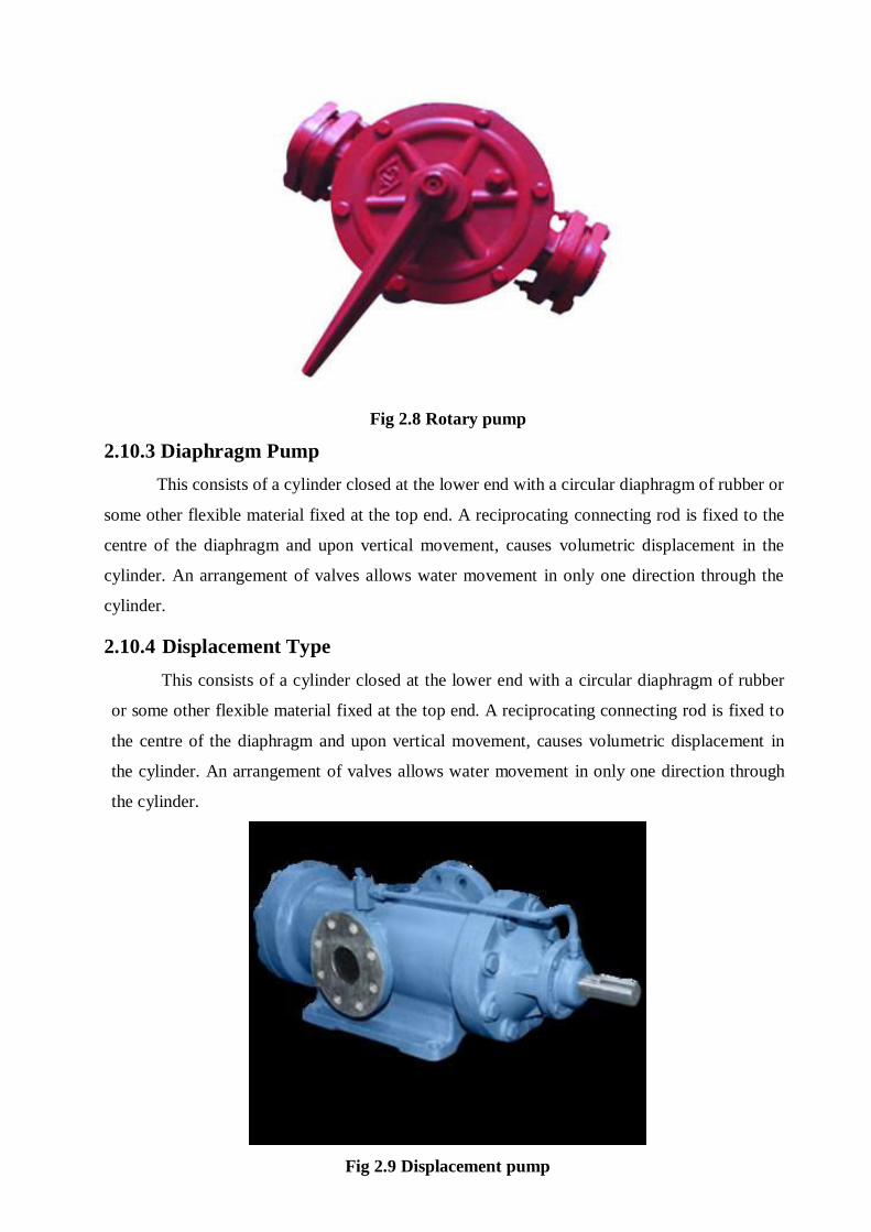
Fig 2.8 Rotary pump
2.10.3 Diaphragm Pump
This consists of a cylinder closed at the lower end with a circular diaphragm of rubber or
some other flexible material fixed at the top end. A reciprocating connecting rod is fixed to the
centre of the diaphragm and upon vertical movement, causes volumetric displacement in the
cylinder. An arrangement of valves allows water movement in only one direction through the
cylinder.
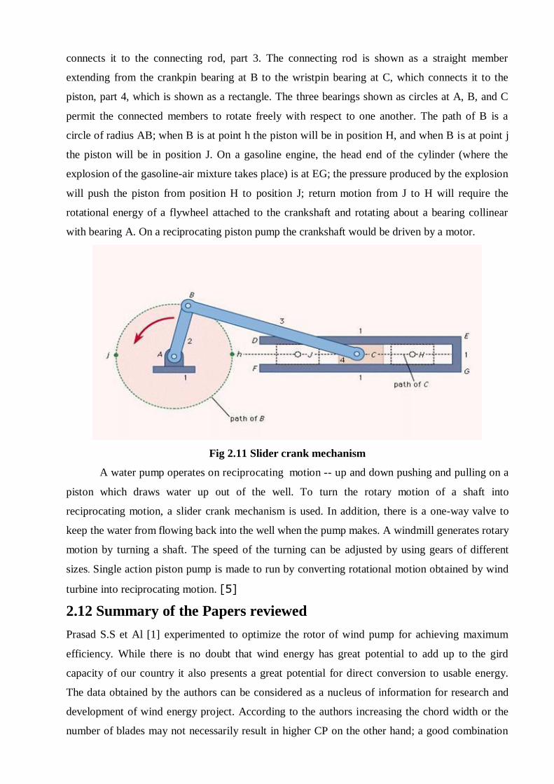
2.10.4 Displacement Type
This consists of a cylinder closed at the lower end with a circular diaphragm of rubber
or some other flexible material fixed at the top end. A reciprocating connecting rod is fixed to
the centre of the diaphragm and upon vertical movement, causes volumetric displacement in
the cylinder. An arrangement of valves allows water movement in only one direction through
the cylinder.
Fig 2.9 Displacement pump

2.10.5 Piston Pump
A Piston type of pumps is normally used for deep wells, the pumps being located the
bore pipe directly underneath the wind-mill and below the water level. Positive Displacement
type piston pumps are used to pump water from river and lakes commonly used in conjunction
with types of rotors, for pumping from open or tube-wells. Hand Pump is a main part in wind
mill operated water pump. This is a small scale water pump. This Pump Is connected to the
Slider Plate in a Other side of a slider crank Mechanism. In Hand Pump One Side is connected
To the Suction Port and Other Side is connected to the delivery or outlet port.
Fig 2.10 Piston pump
Water pumping is very important, most basic wide-spread energy needs in rural areas of the
world. Water supplies like wells, dugouts, rivers can often used for agricultural fields. However,
due to limited availability of power supplies or resources some alternate form of energy has to
be used to supply water from the source to a point of consumption. Wind energy is an important
source of renewable energy that can be used for pumping water in remote locations. A wind pump
is nothing but a windmill used for pumping water, either as a source of fresh water or wells. It is
one of the earliest methods of utilizing the energy of the wind to pump water. [4-5]
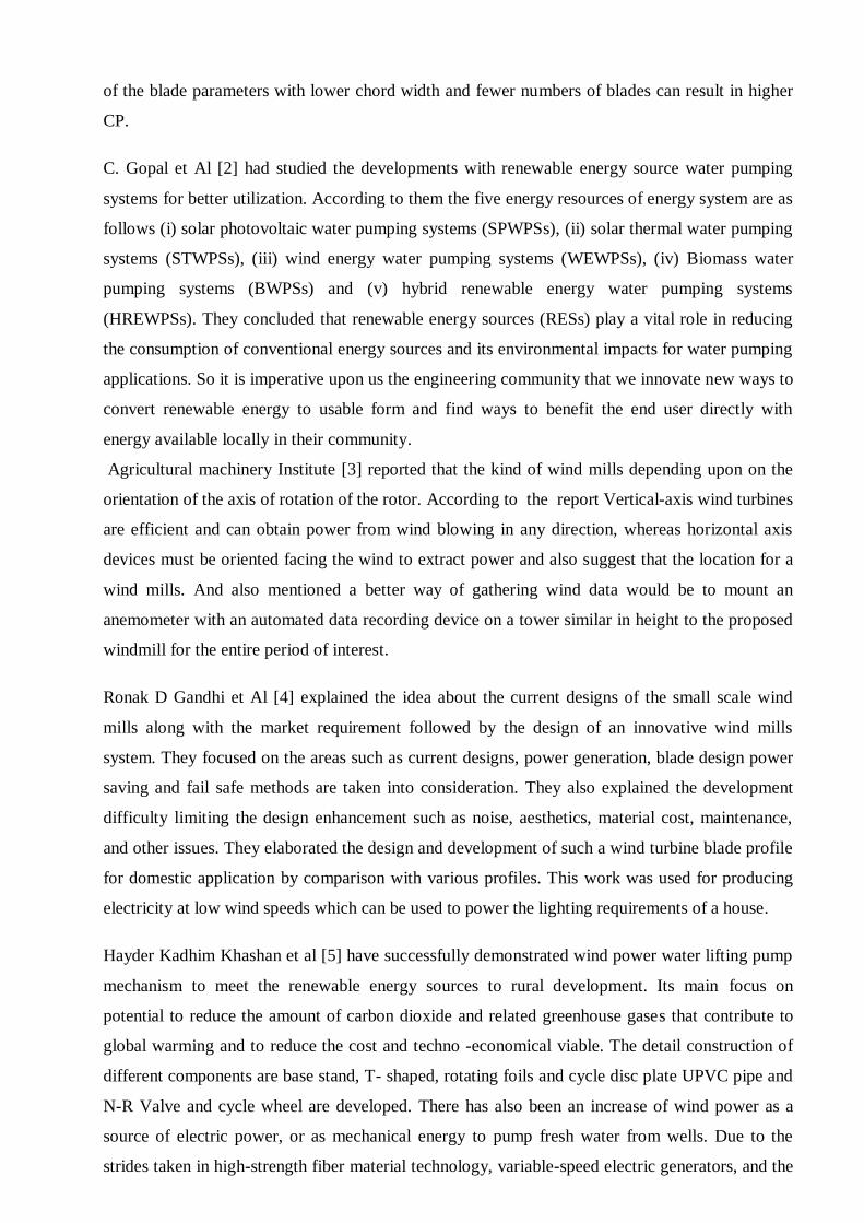
2.11 Slider Crank Mechanism
Slider Crank plate is a Main Component use in a wind – mill. Slider crank Arrangement is
designed to convert straight-line motion to rotary motion, as in a reciprocating piston engine, or to
convert rotary motion to straight-line motion, as in a reciprocating piston pump. The basic nature
of the mechanism and the relative motion of the parts can best be described with the aid of the
accompanying figure, in which the moving parts are lightly shaded. The darkly shaded part 1, the
fixed frame or block of the pump or engine, contains a cylinder, depicted in cross section by its
walls DE and FG, in which the piston, part 4, slides back and forth. The small circle at A
represents the main crankshaft bearing, which is also in part 1. The crankshaft, part 2, is shown as
a straight member extending from the main bearing at A to the crankpin bearing at B, which
connects it to the connecting rod, part 3. The connecting rod is shown as a straight member
extending from the crankpin bearing at B to the wristpin bearing at C, which connects it to the
piston, part 4, which is shown as a rectangle. The three bearings shown as circles at A, B, and C
permit the connected members to rotate freely with respect to one another. The path of B is a
circle of radius AB; when B is at point h the piston will be in position H, and when B is at point j
the piston will be in position J. On a gasoline engine, the head end of the cylinder (where the
explosion of the gasoline-air mixture takes place) is at EG; the pressure produced by the explosion
will push the piston from position H to position J; return motion from J to H will require the
rotational energy of a flywheel attached to the crankshaft and rotating about a bearing collinear
with bearing A. On a reciprocating piston pump the crankshaft would be driven by a motor.
Fig 2.11 Slider crank mechanism
A water pump operates on reciprocating motion -- up and down pushing and pulling on a
piston which draws water up out of the well. To turn the rotary motion of a shaft into
reciprocating motion, a slider crank mechanism is used. In addition, there is a one-way valve to
keep the water from flowing back into the well when the pump makes. A windmill generates rotary
motion by turning a shaft. The speed of the turning can be adjusted by using gears of different
sizes. Single action piston pump is made to run by converting rotational motion obtained by wind
turbine into reciprocating motion. [5]
2.12 Summary of the Papers reviewed
Prasad S.S et Al [1] experimented to optimize the rotor of wind pump for achieving maximum
efficiency. While there is no doubt that wind energy has great potential to add up to the gird
capacity of our country it also presents a great potential for direct conversion to usable energy.
The data obtained by the authors can be considered as a nucleus of information for research and
development of wind energy project. According to the authors increasing the chord width or the
number of blades may not necessarily result in higher CP on the other hand; a good combination
of the blade parameters with lower chord width and fewer numbers of blades can result in higher
CP.
C. Gopal et Al [2] had studied the developments with renewable energy source water pumping
systems for better utilization. According to them the five energy resources of energy system are as
follows (i) solar photovoltaic water pumping systems (SPWPSs), (ii) solar thermal water pumping
systems (STWPSs), (iii) wind energy water pumping systems (WEWPSs), (iv) Biomass water
pumping systems (BWPSs) and (v) hybrid renewable energy water pumping systems
(HREWPSs). They concluded that renewable energy sources (RESs) play a vital role in reducing
the consumption of conventional energy sources and its environmental impacts for water pumping
applications. So it is imperative upon us the engineering community that we innovate new ways to
convert renewable energy to usable form and find ways to benefit the end user directly with
energy available locally in their community.
Agricultural machinery Institute [3] reported that the kind of wind mills depending upon on the
orientation of the axis of rotation of the rotor. According to the report Vertical-axis wind turbines
are efficient and can obtain power from wind blowing in any direction, whereas horizontal axis
devices must be oriented facing the wind to extract power and also suggest that the location for a
wind mills. And also mentioned a better way of gathering wind data would be to mount an
anemometer with an automated data recording device on a tower similar in height to the proposed
windmill for the entire period of interest.
Ronak D Gandhi et Al [4] explained the idea about the current designs of the small scale wind
mills along with the market requirement followed by the design of an innovative wind mills
system. They focused on the areas such as current designs, power generation, blade design power
saving and fail safe methods are taken into consideration. They also explained the development
difficulty limiting the design enhancement such as noise, aesthetics, material cost, maintenance,
and other issues. They elaborated the design and development of such a wind turbine blade profile
for domestic application by comparison with various profiles. This work was used for producing
electricity at low wind speeds which can be used to power the lighting requirements of a house.
Hayder Kadhim Khashan et al [5] have successfully demonstrated wind power water lifting pump
mechanism to meet the renewable energy sources to rural development. Its main focus on
potential to reduce the amount of carbon dioxide and related greenhouse gases that contribute to
global warming and to reduce the cost and techno -economical viable. The detail construction of
different components are base stand, T- shaped, rotating foils and cycle disc plate UPVC pipe and
N-R Valve and cycle wheel are developed. There has also been an increase of wind power as a
source of electric power, or as mechanical energy to pump fresh water from wells. Due to the
strides taken in high-strength fiber material technology, variable-speed electric generators, and the

experience gained through continued development of wind technology, the cost and difficulty of
construction of wind power has significantly decreased to provide more feasible and affordable
wind powered machinery.
Abdulkadir Ali et al [6] studied the VAWT setup for two distinctive arrangement of cutting edges
(steel made and cardboard made) utilizing incompletely and completely cowled design this
investigation brought about high rotational movement for the in part cowled arrangement of the of
cardboard made turbine this likewise brought about heavier the turbine higher the wind speed will
required to create the rotational movement, the lighter turbine came about a superior execution at
all the paces.
Dr. Abdullateef A. Jadallaha et Al [7] has give that the significant point in wind turbine execution
is Blade Element Method and Momentum hypothesis which gives some imperative parameter like
tip speed Ratio, Pitch edge, Number of sharp edge and wind speed. For low power twist turbine
above parameter goes about as a premise crucial on sharp edge plan. The Optimization of wind
turbine execution computation in light of Low twist speed to high twist speed by the changing of
Pitch edge, approach and tip speed Ratio.
Carrigan et Al [8] effectively showed a completely computerized handle for advancing the airfoil
cross-segment of a VAWT. The era of NACA airfoil geometries, half and half work era, and
temperamental CFD were combined with the DE calculation subject to tip speed proportion,
robustness and sharp edge profile plan limitations. The improvement framework was then used to
get an upgraded cutting edge cross-segment for 2 test cases, bringing about plans that
accomplished higher proficiency than the benchmark geometry. The upgraded outline for the first
experiment accomplished proficiency 2.4% higher than the pattern geometry. The expansion in
effectiveness of the upgraded geometry was credited to the end of a main edge division bubble
that was bringing about a diminishment in proficiency and an increment in cyclic stacking. For the
second experiment, the VAWT was given finished geometric adaptability as both the cutting edge
shape and rotor strength was permitted to change amid the improvement procedure. This brought
about a geometry that accomplished proficiency 6% higher than the standard NACA 0015
geometry. This expansion in productivity was a consequence of the 40% diminishing in strength
combined with the 58% increment in thickness, prompting a slight stage move in the torque and
higher general pinnacle execution.
W. T. Chang et Al [9] presented a creative devise called as Omni-Directional –Guide-Vane
(ODGV) coordinated with VAWT ODGV viably enhanced the self-beginning conduct of the
VAWT. At 6 m/s, the rotor rotational speed was expanded by 125% at free-running condition and
the power yield at most extreme torque was 3.48 times higher for the ODGV coordinated VAWT
contrasted with the exposed VAWT.
Ji Yao et Al [10] studied A two dimensional model of three cutting edge H sort vertical pivot wind
turbine was built up in this paper, then the two dimensional flimsy stream field of the vertical hub
wind turbine was reproduced numerically for Standard k - ɛ turbulence models and RNG k - ɛ
turbulence models. The outcomes demonstrated that the impact of various turbulence models on
the speed field is less, on the weight field is generally substantial, and on the estimation of the
aggregate torque is significantly bigger. The angle of the speed and weight around the wind
turbines cutting edge was obvious. The speed field and weight field of the computational space
changed at various time. There would be a thin area of the speed wake inside the specific range
between the wind turbines turn part and the down stream's static part. At the steady speed of the
wind and revolution, the aggregate torque of the vertical pivot wind turbine would change
occasionally.
Seung Yong Min et Al [11] studied an exploration for the execution change of the straight-bladed
vertical pivot wind turbine streamlined investigation; control component outline and its
acknowledgment of 1kw class model are completed. 4 straight sharp edges of 1m traverse length
are utilized and rotor range is settled to 1m. The streamlined investigation demonstrates that the
cycloid wind turbine is conceivable to create more power than settled pitch sort VAWT by
changing its pitch point and stage edge as per wind heading and wind speed. By augmenting the
digressive constrain in each pivoting cutting edge at the particular turning position, ideal pitch
edge variety is gotten. What's more, a few airfoil states of NACA 4-digit and NACA 6-
arrangement are contemplated. Streamlined examination demonstrates execution change of 60%.
Farooq Ahmad Najar et Al [12] have examined wind turbine sharp edge geometric outline and
improvement, streamlined features investigation, wind turbine edge auxiliary plan and progression
examination. Sharp edge geometric outline addresses the plan parameters, including airfoils and
their streamlined coefficients, assault edges, plan tip speed proportion, outline or potentially
appraised wind speed, rotor width, cutting edge streamlined shape with harmony length and curve
disseminations, so that the edge accomplishes an ideal power execution. The geometry of the
cutting edge is S809 a streamlined shape can be gotten in light of the BEM hypothesis concerning
given aerofoil with known streamlined coefficients. Computational liquid elements (CFD) show
has been utilized to figure the streamlined impact on the sharp edge airfoil.
Chapter 3
METHODOLOGY
Different stages involved in the Design and Development of wind mill operated water pump are,
Analytical study.
Design of small wind turbine blades.
Material used for turbine and pump
Fabrication of wind turbine
Project Setup
Experimentation with wind turbines
Use of energy produced from small wind turbines for suitable application like pumping
water.
3.1 Analytical Study
The steps involved in the Analytical study are:
1. Selection of appropriate type for the wind turbine.
2. Analysis on blade design of VAWT by taking the rough drawings.
3. Finding the theoretical power output from the wind turbine and pump.
3.2 Design of Small Wind Turbine Blades
The design of a windmill is a very wide subject and therefore our design is based on data
analysis of various components of windmill and their actual drawings. This includes the rotor
assembly i.e. the blade and the strip, transmission shafts (both vertical and horizontal) the gears,
slider plates and the piston actuating mechanism. The design process started off with analysis of
the existing Windmill designs and their respective operating condition. In order to achieve the
optimum design characteristics such as Torque and power produced by the windmill, various
calculations and structural analysis had to be done as well. The design takes into consideration
ease and simplicity of construction, implementation, and repair, as well as cost and availability of
materials.
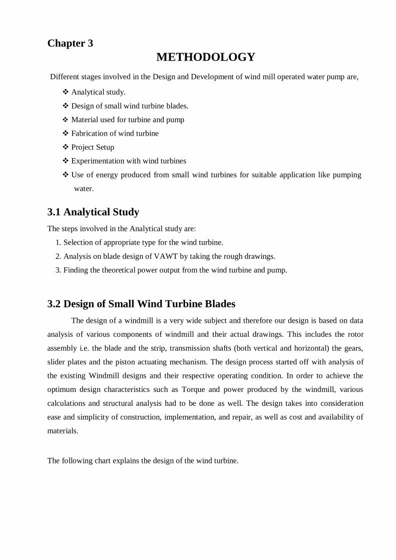
The following chart explains the design of the wind turbine.
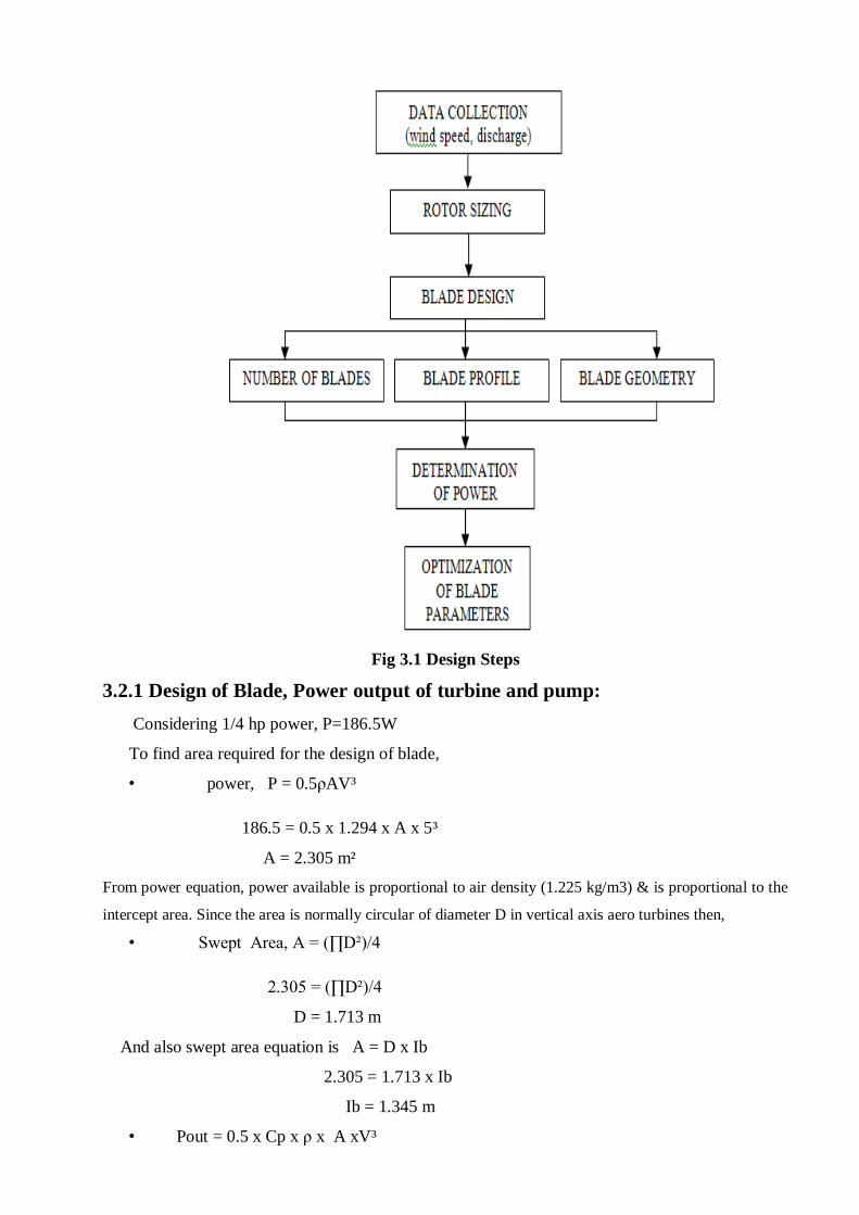
Fig 3.1 Design Steps
3.2.1 Design of Blade, Power output of turbine and pump:
Considering 1/4 hp power, P=186.5W
To find area required for the design of blade,
• power, P = 0.5ρAV³
186.5 = 0.5 x 1.294 x A x 5³
A = 2.305 m²
From power equation, power available is proportional to air density (1.225 kg/m3) & is proportional to the
intercept area. Since the area is normally circular of diameter D in vertical axis aero turbines then,
• Swept Area, A = (∏D²)/4
2.305 = (∏D²)/4
D = 1.713 m
And also swept area equation is A = D x Ib
2.305 = 1.713 x Ib
Ib = 1.345 m
• Pout = 0.5 x Cp x ρ x A xV³
= 0.5 x 0.3 x 1.294 x 2.305 x 5³
Pout = 55.92 W
Assuming transmission efficiency, ηt =95%
• Pin = Pout x ηt
= 55.92 x 0.95
Pin = 53.13 W
We have Phyd = gHq
= 9.81 x 1x 2.305 x 5
Phyd = 113.06 W
• Power required to run the pump, ηp = 70%
P = Phyd/ηp
= 113.06/0.7
P = 161.514 W
Hence, only 161.514 W (0.216 HP) power is required for pumping water under head of 1m.
3.3 Material Used For Turbine and Pump
1. Aluminum sheet and Aluminum Strips
2. Mild steel Rod and Mild steel Strips
3. Flange bearings
4. Bevel gears
5. uPVC pipes
6. Non return valves and bushes
7. Miscellaneous elements
3.3.1 Aluminum sheet and Aluminum Strips The blades are one of the most important components of the wind turbine which influence
the power productivity of the system. The area of blades is directly proportional to the wind
energy absorbed by the system. The area of blades is directly proportional to the wind energy
absorbed by the system.
Fig 3.2 Blade and Strip
In this setup we selected aluminum sheet to make the blades and aluminum strip is used to
give the support for blade members.
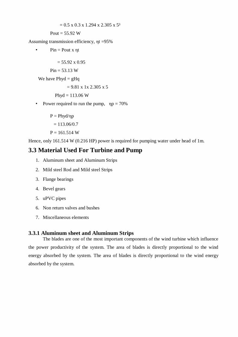
3.3.2 Mild steel Rod and Mild steel Strips The rotating shaft is the vertical shaft to which blade is mounted. Rotating shaft is
supported with flange bearings. Mild steel strip is used to give support for blade at bottom side.
Fig 3.3 Mild steel Strip and rod
3.3.3 Flange bearings
Bearing that are mounted within a flanged housing are used when the bearing mounting
surface is perpendicular to a shaft axis. They are commonly available in two, three, or four hole
configurations. Four-bolt flanged ball bearing units have a square shape with 4 holes for mounting
to accommodate higher loads than two-bolt flanges.
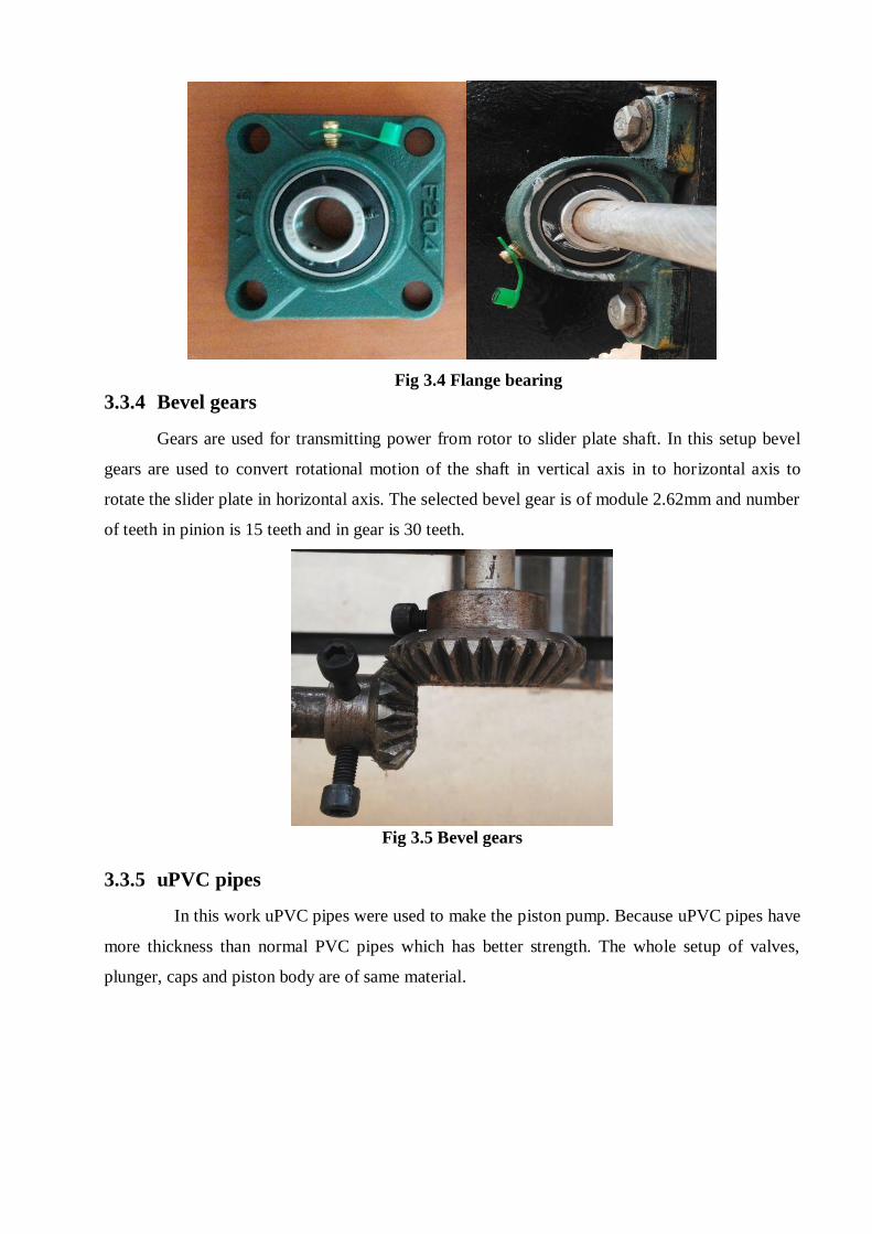
Fig 3.4 Flange bearing
3.3.4 Bevel gears
Gears are used for transmitting power from rotor to slider plate shaft. In this setup bevel
gears are used to convert rotational motion of the shaft in vertical axis in to horizontal axis to
rotate the slider plate in horizontal axis. The selected bevel gear is of module 2.62mm and number
of teeth in pinion is 15 teeth and in gear is 30 teeth.
Fig 3.5 Bevel gears
3.3.5 uPVC pipes
In this work uPVC pipes were used to make the piston pump. Because uPVC pipes have
more thickness than normal PVC pipes which has better strength. The whole setup of valves,
plunger, caps and piston body are of same material.
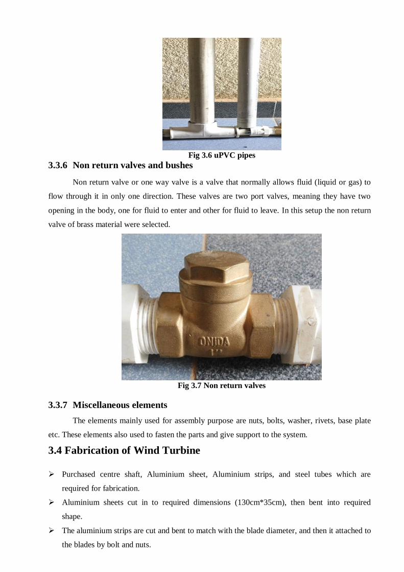
Fig 3.6 uPVC pipes
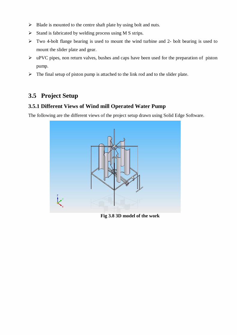
3.3.6 Non return valves and bushes
Non return valve or one way valve is a valve that normally allows fluid (liquid or gas) to
flow through it in only one direction. These valves are two port valves, meaning they have two
opening in the body, one for fluid to enter and other for fluid to leave. In this setup the non return
valve of brass material were selected.
Fig 3.7 Non return valves
3.3.7 Miscellaneous elements
The elements mainly used for assembly purpose are nuts, bolts, washer, rivets, base plate
etc. These elements also used to fasten the parts and give support to the system.
3.4 Fabrication of Wind Turbine
Purchased centre shaft, Aluminium sheet, Aluminium strips, and steel tubes which are
required for fabrication.
Aluminium sheets cut in to required dimensions (130cm*35cm), then bent into required
shape.
The aluminium strips are cut and bent to match with the blade diameter, and then it attached to
the blades by bolt and nuts.
Blade is mounted to the centre shaft plate by using bolt and nuts.
Stand is fabricated by welding process using M S strips.
Two 4-bolt flange bearing is used to mount the wind turbine and 2- bolt bearing is used to
mount the slider plate and gear.
uPVC pipes, non return valves, bushes and caps have been used for the preparation of piston
pump.
The final setup of piston pump is attached to the link rod and to the slider plate.
3.5 Project Setup
3.5.1 Different Views of Wind mill Operated Water Pump
The following are the different views of the project setup drawn using Solid Edge Software.
Fig 3.8 3D model of the work
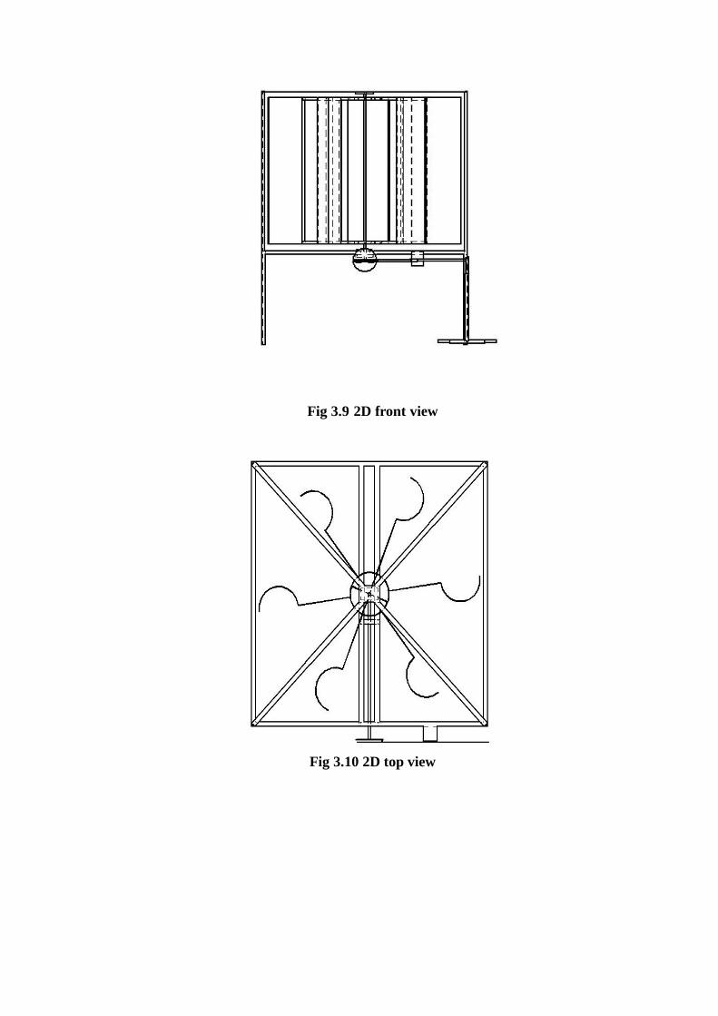
Fig 3.9 2D front view
Fig 3.10 2D top view
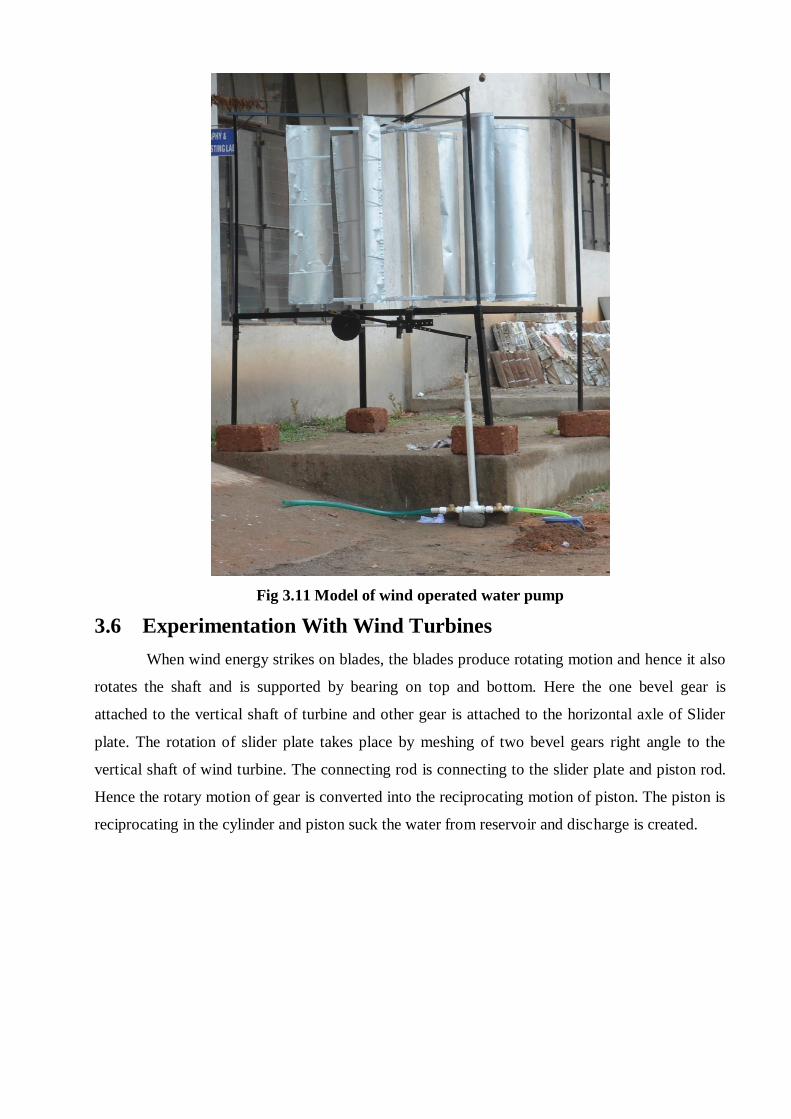
Fig 3.11 Model of wind operated water pump
3.6 Experimentation With Wind Turbines
When wind energy strikes on blades, the blades produce rotating motion and hence it also
rotates the shaft and is supported by bearing on top and bottom. Here the one bevel gear is
attached to the vertical shaft of turbine and other gear is attached to the horizontal axle of Slider
plate. The rotation of slider plate takes place by meshing of two bevel gears right angle to the
vertical shaft of wind turbine. The connecting rod is connecting to the slider plate and piston rod.
Hence the rotary motion of gear is converted into the reciprocating motion of piston. The piston is
reciprocating in the cylinder and piston suck the water from reservoir and discharge is created.
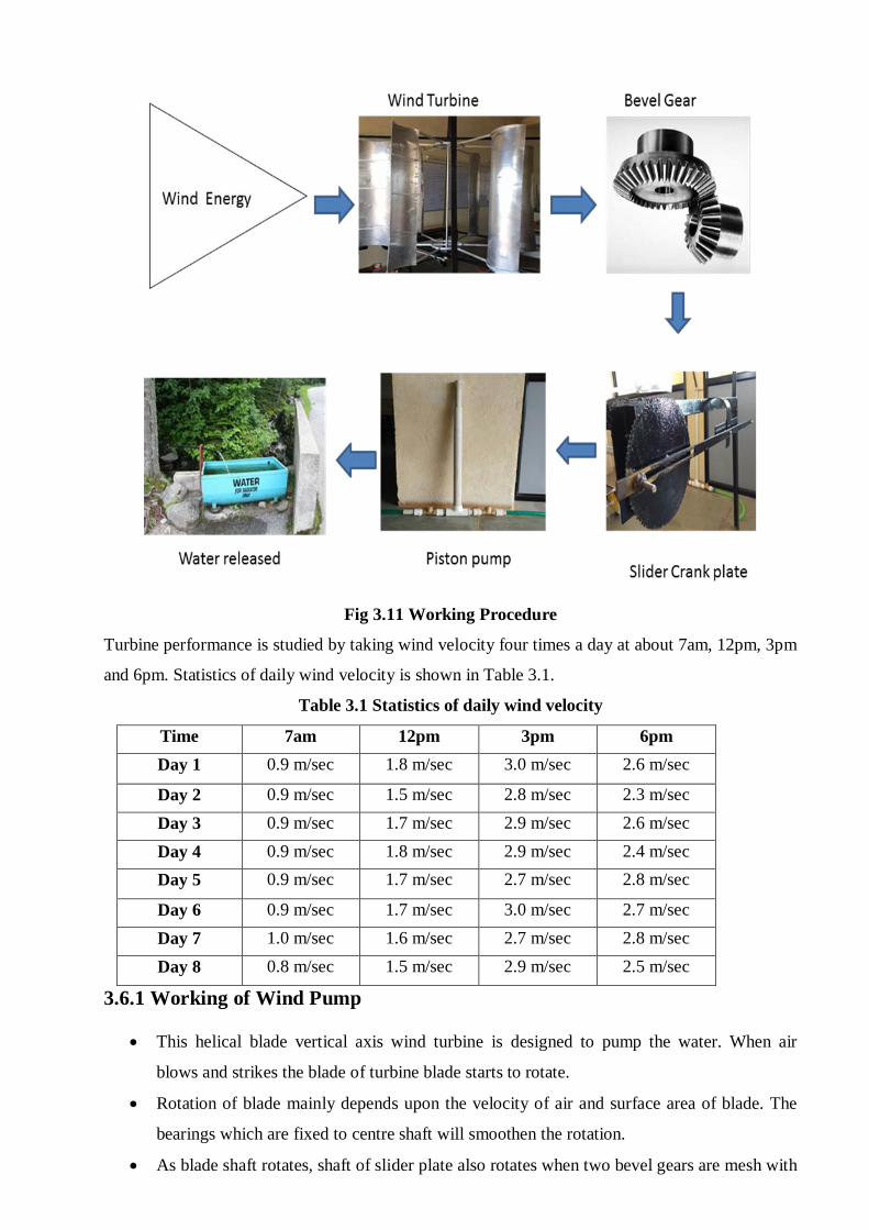
Fig 3.11 Working Procedure
Turbine performance is studied by taking wind velocity four times a day at about 7am, 12pm, 3pm
and 6pm. Statistics of daily wind velocity is shown in Table 3.1.
Table 3.1 Statistics of daily wind velocity
Time 7am 12pm 3pm 6pm
Day 1 0.9 m/sec 1.8 m/sec 3.0 m/sec 2.6 m/sec
Day 2 0.9 m/sec 1.5 m/sec 2.8 m/sec 2.3 m/sec
Day 3 0.9 m/sec 1.7 m/sec 2.9 m/sec 2.6 m/sec
Day 4 0.9 m/sec 1.8 m/sec 2.9 m/sec 2.4 m/sec
Day 5 0.9 m/sec 1.7 m/sec 2.7 m/sec 2.8 m/sec
Day 6 0.9 m/sec 1.7 m/sec 3.0 m/sec 2.7 m/sec
Day 7 1.0 m/sec 1.6 m/sec 2.7 m/sec 2.8 m/sec
Day 8 0.8 m/sec 1.5 m/sec 2.9 m/sec 2.5 m/sec
3.6.1 Working of Wind Pump
This helical blade vertical axis wind turbine is designed to pump the water. When air
blows and strikes the blade of turbine blade starts to rotate.
Rotation of blade mainly depends upon the velocity of air and surface area of blade. The
bearings which are fixed to centre shaft will smoothen the rotation.
As blade shaft rotates, shaft of slider plate also rotates when two bevel gears are mesh with
each other.
The circular rotation of slider plate causes the plunger rod to move up and down by the
help of link rod connected to it.
As the plunger rod move up the suction of water takes place at one side of check valve and
closes that valve after suction.
When plunger rod pushes the water releases at second check valve. The required head can
be maintained by placing the outlet pipe in required position.
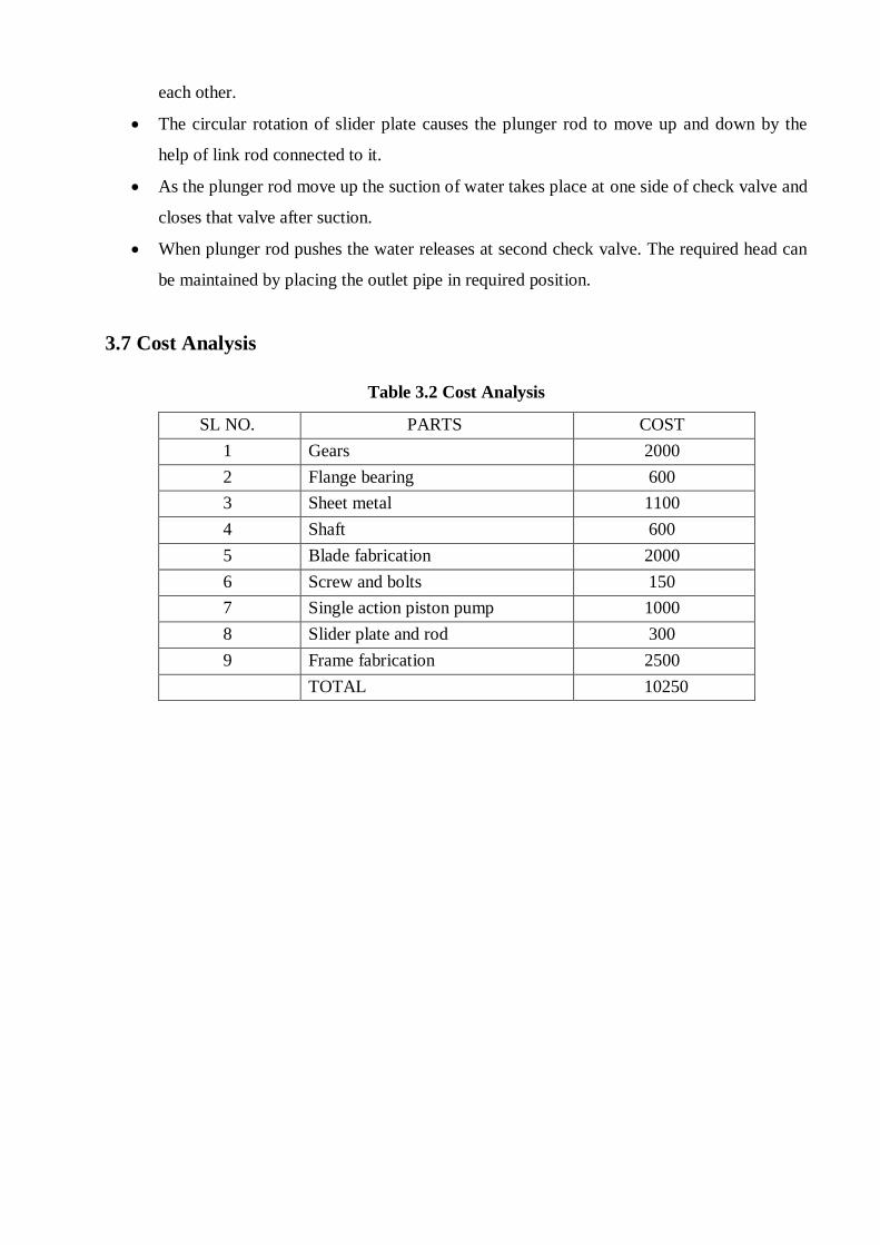
3.7 Cost Analysis
Table 3.2 Cost Analysis
SL NO. PARTS COST
1 Gears 2000
2 Flange bearing 600
3 Sheet metal 1100
4 Shaft 600
5 Blade fabrication 2000
6 Screw and bolts 150
7 Single action piston pump 1000
8 Slider plate and rod 300
9 Frame fabrication 2500
TOTAL 10250

Chapter 4
CONCLUSIONS Following conclusions are drawn from the study and working of Wind mill operated water pump:
1. In the recent era of rapidly developing technology the design of this vertical axis wind
mill generator can be able to full fill certain amount of energy requirements.
2. All materials used are locally available and at a low cost making the model
economically viable.
3. In villages these wind mill can be used for pumping of water when there is no power
supply
4. The ease of construction and design modification of the vertical Windmill pump meant
that the system is well suited for technological transfer to rural-based community
groups.
5. Although it is capital intensive, these technologies will be one of the most cost
effective renewable energy wind pumps in terms of the cost per water pumped in very
low wind regimes.
Scope for future work Efficiency or power output of pump can be improved by optimizing blade parameters such
as blade thickness, blade length, blade profile, number of blades etc.
By keeping solar panels to rotate the wind mill we can pump easily where no power
consumption is required to pump the water.
Efficiency or power output of pump can be improved by changing the gear dimensions
and slider crank mechanism.
REFERENCE
[1] Prasad S.S, Virupaxi Auradi, “Optimized Design of Rotor Blade for a Wind Pump”,
International Journal of Renewable Energy Research, volume 2, number 4, 2012.
[2] C. Gopal, M.Mohanraj, P. Chandramohan, P. chandrasekar,” Renewable energy source
water pumping systems”, Renewable and sustainable energy reviews 25(2013) 351-370.
[3] Wind- powered water pumping systems for livestock watering, Agriculture and Agri- food
Canada.
[4] Ronak D Gandhi, Pramod kothmire, Debarshi Sharma, Bhushan kumbhare, Shubham
Choukade ,“ Design and development of windmill operated water pump”, International
journal on recent engineering research and development, Volume -3, issue -12, December
2015.
[5] Hayder kahdim Khashan, “Design and Development of wind power water lifting
mechanism”, International journal of science technology and engineering| volume 2| Issue
12| June 2016.
[6] Abdulkadir Ali, Steve Golde, Firoz Alama, and Hazim Moria, “Experimental and
Computational Study of a Micro Vertical Axis Wind Turbine”, Procedia Engineering 49
(2012) 254 – 262.
[7] Dr. Abdullateef A. Jadallaha, Dr .Dhari Y. Mahmooda and Zaid A. Abdulqaderb, “Optimal
Performance of Horizontal Axis Wind Turbine for Low Wind Speed Regime”,
International Journal of Multidisciplinary and Current Research 2014.
[8] Travis J. Carrigan, Brian H. Dennis, Zhen X. Han, and Bo P.Wang, “Aerodynamic Shape
Optimization of a Vertical-Axis Wind Turbine Using Differential Evolution”, International
Scholarly Research Network, ISRN Renewable Energy 2011.
[9] W. T. Chong , s. C. Poh, a. Fazlizan, and k. C. Pan, “Vertical axis wind turbine with omni-
directional-guide-vane for urban high rise application”, Journal of Central South
University of Technology.
[10] Huimin Wanga, Jianliang Wanga, Ji Yao, Weibin Yuanb, Liang Cao, “Analysis on the
influence of Turbulence model changes to aerodynamic performance of vertical axis
wind turbine” , Procedia Engineering 31 (2012) 274 – 281.
[11] In Seong Hwang, Seung Yong Min, In Oh Jeong, Yun Han Lee and Seung Jo
Kim,“Efficiency Improvement of a New Vertical Axis Wind Turbine by Individual
Active Control of Blade Motion”.
[12] Farooq Ahmad Najar, G A Harmain, “Blade Design and Performance Analysis of Wind
Turbine”, International Conference on Global Scenario in Environment and Energy
2013.
[13] Kaminsky Chris, Filush Austin et al, “A CFD Study of Wind Turbine Aerodynamics”,
Proceedings of the ASEE North Central Section Conference (2012).
[14] M.A. Kamoji, S.B. Kedare, S.V. Prabhu,” Performance tests on helical Savonius rotors”
Renewable energy 34(2009).
[15] Peter J. Schubel, Richard J. Crossley, “Wind Turbine Blade Design”, Energies 2012, 5.
[16] Piyush Gulve, Dr. S.B.Barve,” Design and construction of vertical axis wind turbine”
International Journal of Mechanical Engineering and Technology (IJMET), ISSN 0976 –
6340(Print), ISSN 0976 – 6359(Online), Volume 5, Issue 10, October (2014), pp. 148-
155 © IAEME.
[17] S.Balamurali P.Chinnamani, B.Hariharan, S.M.Hariprakas, B.Haswin,” Design and
fabrication of windmill reciprocating water pumping system”, IJARIIE-ISSN (O)-2395-
4396, Vol-2 Issue-3 2016.