design analysis and general - nasa
TRANSCRIPT

N A S A TECHNICAL
i
.
NASA Ttl 0-2839
4 z : ‘
Hard copy (HC)
Microfiche (MF) e 75
DESIGN ANALYSIS AND GENERAL CHARACTERISTICS OF FLAT-PLATE CENTRAL-FIN-TUBE SENSIBLE-HEAT SPACE RADIATORS
NATIONAL AEIOWAUTJCS AND SPACE ADMI#ISTRATIO# WASHINGTO#, 0. C. JURE 1365

NASA TN D-2839
DESIGN ANALYSIS AND GENERAL CHARACTERISTICS OF FLAT-PLATE
CENTRAL-FIN-TUBE SENSIBLE-HEAT SPACE RADIATORS
By Arthur V. Saule, Richard P . Krebs, and Bruce M. Auer
Lewis Research Center Cleveland, Ohio
N A T I O N A L AERONAUTICS AND SPACE ADMINISTRATION
For s a l e by the C l e a r i n g h o u s e for F e d e r o i Scient i f ic and T e c h n i c a l In format ion Springf ield, V i r g i n i a 22151 - Price $3.00
..

1 c
CONTENTS
Page SUMMARY . . . . . . . . . . . . . . . . . . . . . . . . . . . . . . . . . . 1
INTRODUCTION . . . . . . . . . . . . . . . . . . . . . . . . . . . . . . . 1
mALYs1s . . . . . . . . . . . Approach . . . . . . . . . . Heat Transfer . . . . . . . . Convection and conduction . Radiation . . . . . . . . . Equivalent sink temperature
1 Surface emissivity . . . . !
R&um& . . . . . . . . . . . I Fin-tube effectiveness . .
. . . . . . . . . . . . . . . . . . . . . . . 5 . . . . . . . . . . . . . . . . . . . . . . 3 . . . . . . . . . . . . . . . . . . . . . . . 6 . . . . . . . . . . . . . . . . . . . . . . 7 . . . . . . . . . . . . . . . . . . . . . . 10 . . . . . . . . . . . . . . . . . . . . . . 10 . . . . . . . . . . . . . . . . . . . . . . 10 . . . . . . . . . . . . . . . . . . . . . . 10 . . . . . . . . . . . . . . . . . . . . . . 12
. RADIATOR CHARACTERISTICS . . . . . . . . . . . . . . . . . . . . . . . . . 12
1 Rankine Cycle Radiator . . . . . . . . . . . . . . . . . . . . . . . . . 14 Thermal characteristics . . . . . . . . . . . . . . . . . . . . . . . . 17 Physical characteristics . . . . . . . . . . . . . . . . . . . . . . . 17
~ Secondary Cooling Radiator . . . . . . . . . . . . . . . . . . . . . . . 20 Thermal characteristics . . . . . . . . . . . . . . . . . . . . . . . . 21 Physical characteristics . . . . . . . . . . . . . . . . . . . . . . . 22
Brayton Cycle Radiator . . . . . . . . . . . . . . . . . . . . . . . . . 25
Physical characteristics . . . . . . . . . . . . . . . . . . . . . . . 25 Comparison of Characteristics . . . . . . . . . . . . . . . . . . . . . . 26 Thermal characteristics . . . . . . . . . . . . . . . . . . . . . . . . 29 Minimum weight radiators . . . . . . . . . . . . . . . . . . . . . . . 29 Designtrade-offs . . . . . . . . . . . . . . . . . . . . . . . . . . . 31 Flow regimes . . . . . . . . . . . . . . . . . . . . . . . . . . . . . 32
I
I Thermal characteristics . . . . . . . . . . . . . . . . . . . . . . . . 25
~
I
. CONCLUDINGREMARKS . . . . . . . . . . . . . . . . . . . . . . . . . . . . 32
APPrnrnS A.SYMBOLS . . . . . . . . . . . . . . . . . . . . . . . . . . . . . . . 34 B . ARMOR THICKNESS AND VULNERABLE ARFA . . . . . . . . . . . . . . . . . 38 C-PRESsuREDROPINRADIATORlvBES . . . . . . . . . . . . . . . . . . . 40 D - G E O M E T R Y O F T U B E S A N D F I N S . . . . . . . . . . . . . . . . . . . . . 44 E.HEADmDESIGN . . . . . . . . . . . . . . . . . . . . . . . . . . . . 47 F.RADIATORWEIGHT . . . . . . . . . . . . . . . . . . . . . . . . . . . 58 G . 59 GENERATION OF MINIMUM WEIGHT CURVES FOR BRAYTON CYCm EXAMPLE . . . .
REFEEUDJCES . . . . . . . . . . . . . . . . . . . . . . . . . . . . . . . . 61
'
DESIGN ANAI;ySIS AND GENERAL CHARACTERISTICS O F FLAT-PLATE
CENTRAL-FIN-TZTBE SENSIBLE--HEAT SPACE RADIATORS
by Arthur V. Saule, Richard P. Krebs, and Bruce M. Auer
L e w i s Research Center
An analysis is reported f o r t he calculation of the character is t ics , per- formance, weight, and area of a single-panel f l a t -p l a t e central-fin-tube sensible-heat space rad ia tor f o r a s e t of thermodynamic and fluid-mechanic conditions. the change i n fin-tube effectiveness along the tube and f i n .
The analysis takes in to account the a x i a l temperature gradient and
An example f o r each type of working f lu id ( l iqu id m e t a l , l iquid, and inert The three examples were selected from representa- g a s ) is discussed i n de t a i l .
t i v e applications t o typ ica l Rankine and Brayton cycle space power-generation systems as w e l l as t o secondary cooling loops. geometric parameters, mass f l o w ra tes , working f lu ids , and flow regimes (turbu- l e n t or laminar) a f f e c t the rad ia tor weight and panel planform area.
Examples show how changes i n
ParticuLar examples indicate that there axe unique ranges of geometric parameters (fin-tube p ro f i l e r a t io , i n i t i a l conductance parameter, and tube inside diameter) f o r minimum weight radiators . e t e r s depend on the phase of the working f lu id (gaseous o r l iqu id) , f low re- gimes, and other operating conditions.
The magnitudes of these param-
INTROWCTION
There a re many applications fo r a heat-rejection device i n s p c e . Vehicle cabins w i l l have t o be conditioned, equipment and instruments w i l l have t o be cooled, and the waste heat from power-generating systems w i l l have t o be ex- pelled. As the payloads become heavier and the missions longer, the cooling loads and the e l e c t r i c power requirements become greater . thermal radiator , or heat-rejecting device, also becomes la rger . I n f ac t , the rad ia tor may become one of the la rges t and heaviest components of a space powerplant (e.g., ref. 1).
As a result, the
Because the rad ia tor is so Large, it must be carefu l ly designed t o mini- mize the s i z e or weight while maintaining i ts thermodynamic and s t ruc tu ra l re- quirements and fluid-mechanic performance i n the space environment. sign of a condenser-radiator, in which the working f l u i d changes from a vapor t o a l i qu id within the radiator , has been discussed in considerable de ta i l i n the literature (e.g., refs. 2 t o 9). However, papers dealing with the
The de-

sensible-heat radiator , i n which the working f l u i d maintains i t s phase (gas o r l iquid) , but loses sensible heat and temperature, are less numerous (refs. 10 t o 14) . I n most of these papers the rad ia tor w a s considered t o be constructed w i t h a central-fin-tube geometry, i n which the tubes carrying the working f l u i d a r e separated by rectangular heat-conducting and -radiating f i n s .
Radiators tha t use a single-phase working f l u i d may be employed, f o r example, f o r the Rankine vapor cycle where a heat exchanger similar t o the shel l and tube type, called a heat-exchanger - condenser, is used t o condense the vapor. passes through an a l l - l i qu id radiator ( ref . 1). sensible-heat radiators are a l so considered fo r secondary cooling systems such as coolant c i r cu i t s required by space environmental control and component cool- ing systems (ref . 14) . other than re jec t ion of waste heat from power cycles. Finally, probably one of the most important uses fo r the sensible-heat radiator is i n a Brayton cycle ( ref . 15), where a radiator that employs an ine r t gas as the working f l u i d may be d i rec t ly coupled t o a gas recuperator or a cooling loop w i t h a gas-liquid heat exchanger and a radiator w i t h l iqu id as the working f l u i d may be added t o the system.
Subcooled l iqu id is provided f o r the condenser by a c i r c u i t that A s another application,
I n t h i s report , secondary cooling means any cooling
Part of the dearth of analyses fo r the sensible-heat radiator may be a t t r ibu ted t o the increased thermodynamic complexity of t h i s radiator over the condenser-radiator. The simultaneous temperature gradients, both ax ia l ly along the tube and the f i n and perpendicularly through the f i n , cause the temperature t o be a t l e a s t two dimensional everywhere i n the rad ia tor . This complication renders the condenser-radiator analysis inadequate f o r the sensible-heat radiator unless t h e a x i a l temperature drop i s very small compared w i t h the terminal temperature ( r e f . 11).
While reference 10 affords a means of determining o r analyzing the per- formance of a given radiator under var iable ambient conditions, it does not give a d i rec t approach t o rad ia tor design t o meet specif ic heat-rejection re- quirements. e t r y (constant-temperature-gradient f in , or f i n s w i t h root thickness equal t o the outside tube diameter) if the temperature drop i n the working f l u i d i s large. either end of the rad ia tor tubes. Similarly, reference 1 2 does not show a header analysis and neglects solar and other incident radiat ion such as thermal radiation from nearby planets and adjacent vehicle components. has developed a simplified method for optimizing a rectangular f in , but it assumes geometric view factors f o r f i n and tube equal t o 1. The tube w a l l thickness, furthermore, i s selected t o s a t i s f y s t ruc tu ra l requirements alone without consideration of meteoroid penetration.
Furthermore, reference 11 requires a r e s t r i c t ion on the f i n geom-
Neither report considers the design o r performance of the headers a t
Reference 12
In addition t o f l a t -p l a t e central-fin-tube sensible-heat space radiators , l i t e r a tu re is a l so avai lable on cycl indrical radiators w i t h in te rna l ly located tubes, where the thermal radiat ion is considered from the convex side alone. Representing such radiators are , fo r example, references 13 and 14. ence 13 assumes a constant f i n effectiveness and tube wal l thickness not deter- mined from present meteoroid penetration theory. thermal radiat ion and headers. Reference 14 considers low-temperature laminar-
Refer-
It a l so neglects incident
2

4
flow f luids , and presents a ver i f icat ion of the r e su l t s of the analysis by appropriate experiments. It appears, however, that t h i s method may be more applicable t o analyzing the performance of a given radiator and l e s s adaptable t o designing a radiator that has t o s a t i s f y certain i n l e t and out le t conditions of temperature and pressure when the heat-rejection r a t e i s fixed.
To fulfi l l . the need for a more comprehensive and f lex ib le fin-tube sensible-heat-radiator design procedure covering a w i d e range of design condi- t ions, the L e w i s Research Center developed the analysis discussed herein. is applicable f o r designing f la t -p la te central-fin-tube radiators that use l iqu id metal, l iquid, and ine r t gas as working f lu ids e i ther in laminar or tur- bulent flow. It includes an analysis of the headers and takes in to account the e f fec t of the solar and a l l other incident radiation by an equivalent sink temperature. The tube and header w a l l thickness i s determined by applying the l a t e s t concepts i n meteoroid protection theory. Rather than using an average f i n efficiency f o r the en t i re radiator, the method discussed i n t h i s report introduces a variable fin-tube effectiveness, which includes radiation inter- change between f i n s and tubes, and thus accounts f o r a x i a l and lateral tempera- tu re changes. dure.
It
The solution is accomplished by a numerical step-by-step proce-
Details of the analysis, equations, and procedures are presented, and some of the thermal and geometric character is t ics o f f l a t -p la te central-fin-tube sensible-heat radiators are demonstrated. Three examples were chosen, one f o r each type of working f luid: l iquid m e t a l , liquid, and ine r t gas. The examples were taken from representative applications t o typ ica l Rankine and Brayton cycle space power-generation systems as wel l as t o secondary cooling loops. In addition, an application of the f la t -p la te central-fin-tube radiator t o multiple-panel arrangements i s discussed.
ANALYSIS
Approach
The analysis used i n this report was developed specif ical ly f o r a single- panel central-fin-tube f la t -p la te radiator emitting from both surfaces, similar t o the one shown i n figure 1. The working f luid enters the radiator through an inlet header that dis t r ibutes the working f lu id t o evenly spaced, s t ra ight , c i rcular , noninternally finned tubes. and diameter and are separated by rectangular f in s . In passing through the tubes, the working f l u i d i s cooled ultimately by thermal radiation from the outer surfaces of the tubes and f ins . f l u i d is collected in to an out le t header.
These tubes are a l l of the same length
A t the discharge end of the tubes the
The shape and s ize of the headers depend on the phase of the f lu id . tapered headers shown i n figure l ( a ) resemble those where gas i s used a s the radiator working f lu id . In t h i s configuration, the gas i s taken in to the inlet header a t one s ide of the radiator and leaves the out le t header a t the opposite s ide of the radiator panel. equal pressure drop across each tube and thereby promote uniform flow dis t r ibu- t ion, s i m i l a r velocity prof i les i n both headers, and equal tube lengths.
The
It w a s assumed that t h i s arrangement may approach
The
3

-
-
Tube-
(a) Gas working fluid.
Fluid in 1 Ti
Header7 ,-Fin
(b) Liquid working fluid.
Figure 1. - Radiator panel and header arrangement.
headers for l iquids or l iqu id metals, because of t h e i r r e d t - v e l y sma-, size , were assumed t o have constant diameters, as shown i n figure l ( b ) .
The objective of the analysis is t o generate a rad ia tor geometry t h a t meets t h e design thermodynamic, fluid-mechanics, and environmental requirements and t o determine the radiator panel planform area and weight. T h i s objective has been accomplished i n reference 5 f o r a direct-condensing radiator i n which the temperature of the tube surface and f i n base w a s nearly constant i n the direc- t i o n of f l u i d flow. pendicular t o the tube ax is and t h e radiant interchange between f i n and tube, and between adjacent tubes, w a s accounted f o r by an overal l f i n and tube effec- tiveness i n t h a t reference.
The temperature gradient i n the f i n i n a direct ion per-
4

The heat-transfer analysis f o r the sensible-heat radiator with which t h i s report is concerned i s inherently more complicated than f o r the direct- condensing radiator because of the additional temperature gradient i n the tube a x i a l direct ion. assumed t o be divided in to s t r i p s perpendicular t o the tube axis . are then assumed t o be isothermal, and an analysis fo r thermal radiat ion similar t o that described i n reference 5 is applied t o each strip-. radiat ion rate fo r the e n t i r e radiator is then equal t o the sum of the heat radiat ion r a t e s *om each s t r i p . required accuracy i n the heat transfer.
To circumvent this d i f f icu l ty the sensible-heat radiator is These s t r i p s
The heat
The number of s t r i p s used is dependent on the
The general approach t o the radiator design begins with the determination of the f i n and tube geometry i n the radiator panel. on the heat-transfer character is t ics , the meteoroid-protection requirements, and the pressure drop prescribed f o r the tube. i n t o account the e f f ec t of the temperature drop between the working f l u i d and the tube w a l l and the temperature drop through the tube armor as wel l as the temperature gradients and radiant interchange previously discussed. of incident radiat ion from such sources as the Sun, nearby planets, o r objects adjacent t o the radiator a r e incorporated in to an equivalent sink temperature (e.g., r e f . 16). Details and the derivation o f the heat-transfer analysis axe given i n the succeeding section of this report, and a l l symbols used are de- fined i n appendix A.
This geometry is dependent
The heat-transfer analysis takes
The effects
The analysis of the meteoroid protection requirements is based on refer-
The tube and f i n geometry and the panel planform area axe calcu- ence 17 and i s given i n appendix B. appendix C. l a t ed from the equations given in appendix I).
The pressure drop analysis can be found in
After the panel has been designed, the shape and w e i g h t of the headers a re found in accordance with the analysis in appendix E. The maximum diameter of the headers is determined so that the pressure drop i n the header w i l l be a prescribed value f o r a header length equal t o the panel width. The heat radi- a ted from the headers i s assumed t o be negligible compared w i t h the t o t a l h e a t - re jec t ion r a t e from the radiator . This assumption has a l s o been checked i n ap- pendix E and is shown t o be the case providing that the prescribed pressure drop i n the headers w i l l minimize the t o t a l radiator weight f o r a given tube inside diameter, fin-tube p ro f i l e r a t io , and i n i t i a l conductance parameter. analysis i s completed after the t o t a l and component weights of the radiator have been determined from the equations in appendix F.
The
In order t o make the radiator-design calculations, ce r t a in inputs are re- These include the radiator heat load, expressed i n terms of the inlet quired.
and e x i t temperatures T i and Tf, respectively, mass flow r a t e i, and speci- f i c heat of the working f l u i d Other inputs required a re the allowable pressure drop in each header ( L I P ) ~ , H and (AP)o,~, the pressure drop i n the tubes (LIP)t, and f o r those radiators i n which a gas i s the working f luid, the pressure l eve l P i . It is a l s o necessary t o specify the sink temperature T, and the constants describing the meteoroid penetration phenomenon (see appen- dix B ) . diameter
cp.
Three parameters describing the f i n and tube geometry (the tube inside D i n , the r a t i o of the half-fin width t o the tube outside radius L/Ro,
5

.
and the so-called f i n conductance parameter the tubes) are a l s o input variables. Physical and thermal properties of the working f lu id and radiator material such as the thermal conductivity k, the viscosity p, the density p , the gas constant R, and the hemispherical emissivity E, complete the quant i t ies t h a t must be supplied.
AI, e.g., ref . 5, a t the i n l e t of
The outputs consis t chief ly of component dimensions and weights. These include the number of tubes N, the length o f the tubes Z, the armor thickness 6,, the outside tube diameter area the in l e t and out le t headers D ~ , H and D,,H, respectively, and the t o t a l vulnerable area of the two headers AH,^. The weights include the t o t a l radia- t o r weight W r , f i n weight WF, tube weight W t , header weight (WH f o r gases or WL,H f o r l iquids >, and l iqu id content weight WI f o r l iqu ids . Other out- puts include the inside f i lm and overa l l heat-transfer coeff ic ients hin and Uo, respectively, the f l u i d velocity a t the i n l e t t o the tube average Reynolds number i n the tube
Do, t he f i n thickness t, the panel planform Ap, the vulnerable area of the tubes At,v, the maximum inside diameter of
V i , and the R e .
Although the procedure w a s wr i t ten f o r a single-panel rad ia tor configura- t ion, it can a l so be used t o design one un i t of a segmented radiator having p ident ical segments i n which a l l segments a re e i ther interconnected or isolated, providing that there i s no radiant interchange among the individual segments and that no segment ac t s as a shield f o r meteoroids fo r any other segment. If a l l segments a re interconnected, t h a t is, i f the f a i lu re of any s ingle segment w i l l render the en t i r e radiator inoperative, then one of the segments of a radiator having a flow r a t e and an overa l l probabili ty of no meteoroid penetration equal t o
and a probabili ty p(0) = P(0) 1/5 as inputs t o the computer program described
m P(0) can be designed by using a mass f l o w r a t e of i /F
herein. On the other hand, i f a l l segments can be isolated, t h a t is, if only the punctured segments become inoperative, then the probabi l i ty of no meteoroid penetration of a s ingle panel dis t r ibut ion function
p ( 0 ) is obtained from the cumulative binomial
where P(0) is the probabi l i ty of having Fs or more segments not punctured and p(0) i s the probabi l i ty of each of ident ica l segments. The mass flow r a t e in each of these p segments, however, i s calculated the same way a s fo r interconnected segments.
-
Heat Transfer
The net heat t ransfer i n sensible-heat radiators can be solved by simpli-
The method adopted herein divides f i e d numerical methods if isothermal radiant interchange and no a x i a l heat con- duction are approximated loca l ly ( ref . 18 ).
6

the radiator panel in to a number of elemental s t r ip s , each of which is assumed t o be isothermal as shown i n figure 2. is chosen so that each s t r i p radiates heat a t the same ra t e . that the temperature drop of the
The length of each s t r i p (bh
This implies
f lu id i n each s t r i p is the same, but the incremental length (Az) j varies . The steady-state energy balance is now written f o r each s t r i p i n a step-by- s t e p procedure. Assumptions adopted i n various phases of the development are indicated i n the process of the analysis.
Convection and conduction. - The Fluid in 1 Ti
(a) Planform section of radiator panel. loss of the sensible heat of the f lu id i n any elemental s t r i p fo r a l l tubes is :Tube 1 .i-T~be 2
+ = 3600rhcp AT = const (1)
where (b) Typical cross section.
Figure 2. - Schematic drawing of radiator panel shaving isothermal strips used for numerical analysis.
T i - Tf m = = const n
In t h i s analysis it is assumed that the flow ra te temperatures a t the inlet T i and a t the exit Tf, and the number of the elements n a re known quantit ies.
A, specific heat cp, f l u i d
The sensible-heat energy, i n turn, i s transferred t o the inside surface of the tubes by convection and t o the outside surface of the tubes by conduction. I n terms of an overal l heat-transfer coefficient,
where
is the tube outside surface area of any radiator element The f lu id temper- ature T j represents the average f l u i d bulk temperature i n the tube element j
and is obtained from the known i n l e t temperature T i and LYC as
j .
Tj = T i - AT(j - 0.5) (4 )
The overal l heat-transfer coefficient based on the outside tube area i n
7

.
equation (3) is obtained f rom the re la t ion
1 u = Do DO
0 - 'in + Do In Din
3600hin 2%
where hin is the average film coefficient of heat t ransfer , and the constant 3600 is used t o make uni t s of hin and Uo consistent. If it can be assumed tha t the radial temperature drop i n the tube w a l l s is negligible, t ha t is,
DO DO
Din Din Do In - 2% '' 3600hin
equation (5a) becomes
Equation (5b) may be used fo r gases and most of the nonmetallic l iquids, while equation (5a) i s recommended fo r l iquid metals with high
I n writ ing equation (5) it was assumed that the heat radiated from inside
hin.
of the tube w a l l s from the hot t o the cold end i s negligible, and that the working f lu id is transparent t o the in te rna l radiation. Since the flow i s con- sidered subsonic, the f r i c t i o n a l heating is a l so ignored. It i s a l so assumed that the inside and outside tube w a l l temperatures a re uniform circumferen- t i a l l y .
Heat-transfer coefficient in turbulent flow: For cooling gases and non- metallic l iquids of moderate viscosity, reference 19 gives the following correlation for heat-transfer coefficient for turbulent flow i n long smooth tubes (Z/Din 2 60):
!A w 0.8 pr0.3
Din R e hin = 0.023 -
For cooling l iquid metals the following equation is used ( r e f . 1 9 ) :
k, 0.4 pr0.4 hin = 0.625 - R e Din
The properties of the working f l u i d such as thermal conductivity and viscosi ty i n the Reynolds and Prandtl numbers i n equation ( 6 ) were evaluated a t the arithmetic mean of the f l u i d i n l e t and out le t bulk temperatures of the radiator . Tn case of the l iquid or l iquid metal f luids , the density and a l so the specific
8

heat were determined i n the same way. "he specific heats of the ine r t gases were taken as constant and independent of the temperature. gases, the density w a s computed from the ideal gas l a w :
For the monatomic p = P/RT.
Presently, there i s a scarci ty of experimental data f o r the turbulent-flow heat-transfer coefficients i n long smooth tubes with cooling by thermal radia- t ion. environment conditions, equations (6a) and (6b) fo r convection heat t ransfer w e r e chosen because they conveniently allow the use of average bulk tempera- tures of the f lu id . cooling e f f ec t through the Prandtl number raised t o the 0.3 power instead of the 0.4 power as it is conventionally used for heating of the f lu ids
lacking empirical correlations that may be applicable t o the space
Equation (sa) a lso accounts, a t least partly, f o r t he
Heat-transfer coefficient in laminar flow: There is no mathematical solu- t ion known t o be available t o date of the laminar flow i n space radiator tubes where the wall temperature varies nonlinearly and wall heat flux varies with the fourth power of the wall temperature. As i n turbulent f low, there is also a lack of experimental data for laminar flow being cooled by thermal radiation. Therefore, when the flow i s laminar, the following equation fo r heat t ransfer by forced convection was used for a l l three types of the working f lu ids ( l iqu id m e t a l , l iquid, and ine r t gas}:
kw Din
bin = 4.36 - (7)
Equation ( 7 ) arises from a limiting Nusselt number equal t o 4.36 f o r filly developed laminar flow (e.g. , ref. 19) . same f o r e i ther constant w a l l heat flux o r l i n e a r w a l l temperature. fo r constant w a l l heat f lux, the thermal-entrance length i s one-half the thermal-entrance length f o r the linear w a l l temperature (e.g . , ref. 19). thermal-entrance length i s that distance from the beginning of the heat trans- f e r a t which the Nusselt number becomes independent of the length. If the tubes a re not suf f ic ien t ly long fo r f i l l y developed laminar flow, the heat- t ransfer coeff ic ient may be higher than that given by equation (7), and the use of t h i s equation w i l l y ie ld conservative resul ts .
This l imiting Nusselt number 5's the However,
The
Heat-transfer coeff ic ient i n t rans i t ion region: Heat transfer in turbu- l e n t pipe flow is determined by different laws than i n l a m i n a r flow. fore, f o r the same f l u i d properties, Reynolds number, and tube diameter, equation (6) w i l l y ie ld d i f fe ren t r e su l t s than equation (7), indicating a sharp discontinuity. In prac t ica l applications, however, it can be expected that there is a gradual t rans i t ion between laminar and turbulent regimes. flow i n t h i s regime may be very unstable and actual performance may d i f f e r con- siderably f romtha t predicted, there i s no generally accepted heat-transfer equation available f o r the t rans i t iona l regime. t o the extent of t h i s region. According t o reference 20, by carefully avoiding a l l disturbances, the Reynolds number f o r t ransi t ion may extend from 2300 t o 500 000. However, under prac t ica l conditions as they prevai l in indus t r ia l applications, flow i n tubes usually is considered turbulent when the Reynolds number exceeds 3000. For the purpose of this report, the flow w a s considered f u l l y developed laminar up t c a Reynolds number of 2300, and filly developed
There-
As the
There is a l so no agreement as
9

I turbulent when the Reynolds number i s equal t o or greater than 3000. Reynolds number f a l l s between 2300 and 3000, the flow w a s assumed t o be t rans i - t i ona l and calculations were made with both se t s of equations.
When the
Radiation. - The net heat from the outer surface of a radiator s t r i p i s radiated to unobstructed space. Since a f la t , symmetrical geometry radiator is considered, the following re la t ion is wri t ten fo r the same equivalent sink temperature on each surface of the radiator
(q). = ~ u € R , N ( & ) ~ J
where the fin-tube prof i le r a t i o space
d iv idua lne t emission contributions from each surface have t o be t reated.
L/Ro and the equivalent sink temperature of
remains t o be defined. If unequal sink temperatures a re involved, the in- Ts ( r e f . 1 6 ) a r e independent variables, and the fin-tube effectiveness
q j
Equivalent sink temperature. - A s shown i n reference 16, heat inf lux from the external space environment can be neglected f o r high-temperature radiators (greater than about 1500' R ) . error involved i n neglecting the sink temperature may be considerable. of the sensible-heat applications f a l l i n the l a t t e r category, the heat influx from the external space environment (space, Sun, and nearby planets) was accounted for i n t h i s analysis. i n a s ing le quantity called the equivalent sink temperature of space. Although it w a s treated as an independent variable t o simplify the mathematics, the equivalent sink temperature depends on many factors : (1) the vehicle orb i t ( i . e . , circular, e l l i p t i c a l , polar, equatorial) , posit ion (sun, shade), and al t i tude; and ( 2 ) the radiator configuration (cylindrical , plane, e tc . ) and surface properties (emissivity, absorpt ivi ty) . Details on how t o evaluate the equivalent sink temperature of space a re given, for example, i n reference 16 .
For lower temperature radiators, the approximate A s most
The e f fec ts of the heat influx were combined
Surface emissivity. - Theoretically, when both f ins and tubes have non- black surfaces, as i n a l l p rac t ica l cases, an extensive computing e f fo r t would be required t o achieve accurate numerical resu l t s fo r the heat radiated, as demonstrated i n reference 21, even i f a gray body i s assumed. cumvent the analyt ical d i f f i cu l t i e s involved, reference 5 presents an approxi- mate method of solution by assuming tha t the radiator surfaces - are isothermal not only axial ly , but a l so l a t e ra l ly . An emissivity function E, ca l led the apparent emissivity of the cent ra l fin-tube cavity, is derived, and it i s postulated that the net radiation fo r a gray body is equal t o the net radiation fo r a blackbody multiplied by the apparent emissivity of the cavity. there is no known evaluation, however, of how the apparent emissivity method of reference 5 compares with an exact method (e.g., with one outlined i n r e f . 21) . for radiation from tubes were modified by a r b i t r a r i l y including the hemispheri- c a l emissivity E as a d i rec t multiplier. A similar approach i s used i n refer- ence 5 f o r optimizing condenser-radiators (e.g., eqs. (39) and (40) of ref. 5 ) .
In order t o c i r -
Presently,
Therefore, fo r simplicity i n t h i s analysis, the blackbody equations
Fin-tube effectiveness. - The fin-tube effectiveness q j i n equation (8)
10

'
is evaluated by following the theory of fin-tube effectiveness of condenser- radiators with isothermal base temperature, as discussed i n reference 5. The fin-tube effectiveness for an isothermal s t r i p t o r including the effect ive sink temperature of space is writ ten i n a similar way as
j of the sensible-heat radia-
where h j is the conductance parameter, 6 is a dimensionless temperature r a t io , and 5 is an angle factor, a l l defined in the following paragraphs.
Equation (9 ) is based on a dimensionless f i n temperature defined as the
-
r a t i o of l oca l f i n surface temperature t o local temperature of the base of the f i n
T- ej =
0, j
where x - is the dimensionless distance f r o m the base surface along the f i n
width, x/L, as shown i n figure 2(b).
The dimensionless sink temperature i s defined as the r a t i o of equivalent sink temperature t o loca l temperature of the base of the f i n
The conductance parameter hj i n equation ( 9 ) is a dimensionless quantity defined as
It d i f fe rs from the blackbody conductance parameter N, of reference 5 i n that the l a t t e r does not contain the hemispherical emissivity E so that
h = ENC
Because of the a x i a l temperature gradient, h along the length of the tube according t o
f o r sensible-heat radiators varies
3 To, j A * J = %(To,)
The angle factor Fx i n equation ( 9 ) represents the fract ion of thermal - energy leaving the f i n sLrface a t location tubes (1 and 2 i n f i g . 2 (b ) ) , or
- X, which i s incident on adjacent
11
.
These angle factors a re dependent not only on posit ion reciprocal of the fin-tube prof i le r a t i o factors is given, fo r example, i n reference 5.
x but a l so on the L/Ro. The expFession fo r both angle
Equation ( 9 ) cannot be solved analyt ical ly; therefore, a numerical solu- The method of solut ion of equation ( 9 ) i s given i n r e fe r - t ion i s necessary.
ence 22. effectiveness 7 is plot ted against l oca l conductance parameter hj (eq. ( 1 2 ) ) with several l oca l sink temperatures r a t i o s L / R ~ as parameters.
Figure 3 shows the r e su l t s of t h i s solution, where loca l fin-tube
O s , j and fin-tube p ro f i l e
Thus far, heat-transfer considerations alone have provided two basic equations: equation (3) f o r convection and conduction, and equation (8 ) f o r thermal radiat ion. These equations contain four unknown quant i t ies , namely, incremental length outside tube diameter Do, number of tubes N, and tube outside temperature ToJj. obtained from the meteoroid protection (appendix B ) and pressure drop (appen- dix C ) requirements. t o t a l and component weights were obtained from equations and procedures as out- l ined in appendixes D t o F and as discussed previously i n the Approach section.
Two more re la t ions a r e required and these were
Finally, rad ia tor dimensions, panel planform area, and
RADIATOR CHARACTERISTICS
The purpose of t h i s section is f i rs t t o i l l u s t r a t e the basic thermal character is t ics of sensible-heat radiators , such as the var ia t ions of the f l u i d and wall temperatures, t he conductance parameter, and the fin-tube effect ive- ness. parameters, such as tube inside diameter, fin-tube p ro f i l e r a t i o , and i n i t i a l conductance parameter, have on the area and weight as w e l l as other physical character is t ics of the radiator . To f u l f i l l the foregoing objectives, three typical sensible-heat radiators fo r use i n space were taken as examples. calculations f o r these examples were based on the previous analysis and were obtained from the equations and procedures outlined herein.
It is intended a l so t o show the effect that changes i n the geometric
A l l
The f i r s t radiator example i l l u s t r a t e s the charac te r i s t ics of a large heat-rejection u n i t operating a t a high-temperature l e v e l with a moderate t e m - perature difference. The temperature l eve l i s suf f ic ien t ly high t h a t a l i qu id metal i s required as the working f luid, and the equivalent sink temperature equal t o zero can be used. Such a radiator i s typ ica l of one t o be used i n conjunction with a condenser - heat-exchanger and would serve as the heat re- jector, f o r example, f o r a 1000-kilowatt e l ec t r i c Rankine cycle power- generating system.
The second radiator example has a small heat-rejection rate, a low- temperature level, and a small temperature drop. The working f l u i d chosen is
12

VI- VI al != al >
U al
al
.- e - c 9 c
S U .-
1.0
. 9
.a
. 7
. 6
.5
0 1 2 3 4 5 Conductance parameter, Aj
Figure 3. - Fin-tube effectiveness for central-fin-tube flat-plate radiator.
13
*
an organic l iquid. The temperature l eve l is suff ic ient ly l o w t h a t the l iqu id does not decompose, and the pressure required t o keep the f l u i d from vaporiza- t ion is not excessive. A typical application of t h i s radiator would be f o r secondary cooling, fo r example, cooling of seals , bearings, a l ternator , con- t ro l s , and pump motors.
The th i rd class can be characterized as radiators w i t h comparatively low heat-rejection rates , moderate temperature level , and large temperature d i f fe r - ences. The application is typica l of a d i r ec t heat-rejection system (gas flow i n radiator) t o be used i n a Brayton cycle that generates several kilowatts of e lec t r ic power.
f The inputs for the computer calculations a re obtained from the operatin conditions of the three given cycles (Rankine, secondary cooling, or Brayton j from selected tube, f i n , header, and l i n e r materials; and from meteoroid pro- tect ion and environment requirements. In addition, there i s a choice of sev- e r a l independent parametric variables. The specif ic inputs required t o obtain the resu l t s f o r the par t icular three examples described a re given i n tab le I. Inputs l i s t e d i n table I ( a ) t o ( c ) were kept constant, while prof i le ra t ios , tube inside diameters, and i n i t i a l conductance parameters ( t ab le I( d ) ) were varied one a t a time over the ranges indicated i n the table . Thus, a ser ies of outputs w a s generated tha t was used t o describe the radiator thermal and physical character is t ics .
The radiator thermal properties include the ax ia l and r ad ia l temperature variations and ax ia l changes of conductance parameter. This class of outputs i s augmented by ax ia l variations that occur i n fin-tube effectiveness and the fraction of <heat radiated from the f in s . These r e su l t s for radiators t h a t have weights near minimum a r e presented f i rs t .
The outputs describing radiator physical character is t ics a re discussed next. It w i l l be shown how the parametric variations of tube inside diameter, fin-tube prof i le ra t io , and i n i t i a l conductance parameter a f f ec t the t o t a l radiator weight, planform area, component weights, number and length of tubes, length, width, and thickness of the f in s , and header length and inside diameters
After the thermal and physical character is t ics of the three radiators have been presented, they a re compared i n the closing portion of t h i s section. Any radiator character is t ics t ha t might be a t t r ibu tab le t o a par t icular range of heat-rejection r a t e , temperature level, temperature difference, or class of working f l u i d w i l l a l so be indicated.
Rankine Cycle Radiator
A schematic diagram of the arrangement i n which a sensible-heat radiator may be used i n conjunction with a condenser - heat-exchanger a s the heat- rejection system fo r a Rankine cycle is shown i n f igure 4(a). cycle working f l u i d enters one s ide of the condenser from the turbine and leaves as a subcooled l iquid. f lu id a s would be the case i n a Rankine cycle with a condenser-radiator
Wet vapor of the
A pump i s used t o c i rcu la te the cycle working
14

0.0625 - 0.50 -------------
6 - 16 0.2 - 1.0
0.750 - 1.50 -------__---
2 - lo 0.2 - 2.0
. TABLE I. - CALCULATION INPUTS
( a ) Operating condi t ions
I n p u t s Class of r a d i a t o r s I Name Symbols Uni t s Rankine Secondary cooling
Heat - re jec t ion rate Working f l u i d Flow ra te S p e c i f i c h e a t Viscos i ty Thermal conduct iv i ty Gas cons tan t F l u i d d e n s i t y I n 1 e t tempera tur e E x i t temperature I n l e t pressu-re Tube-pressure-drop
Header-pressure-drop
Tube p r e s s u r e drop Header p r e s s u r e drop
r a t i o
r a t i o
Btu/sec 4367 NaK 138.83 0.2097
0.4144~10-2 0.1111~10-3
----------- 45
1700 1550
lb / sec Btu/( l b ) (OR)
l b / ( f t ) ( s e c ) Btu/( s ec) ( f t ) (OR
f t - lb / ( l b ) (OR)
lb /cu f t OR
OR
lb/sq f t _-__---_---__---_
lb/sq f t lb / sq f t
432 72
1440 200
( b ) Se lec ted m a t e r i a l p r o p e r t i e s
Mater ia l ( f i n s and
Mater ia l ( l i n e r )
Sonic v e l o c i t y i n armor material
F in d e n s i t y Header d e n s i t y
Tube d e n s i t y Liner dens i ty
Fin thermal con- d u c t i v i t y
Surface e m l s s i v l t y
armor) Beryllium
Columbium a l l o y
35 700
115 115 115 530 54
0.9
f t / s e c
lb/cu f t lb/cu f t
lb/cu f t lb/cu f t
B t u / ( h r ) ( f t ) ( o R )
_____------__--_
( e ) Meteoroid p r o t e c t i o n and environment
P r o b a b i l i t y of no p e n e t r a t i o n
Operation time Occlusion f a c t o r Meteoroid d e n s i t y
Average meteoroid
Meteoroid m a s s d i s -
S p a l l i n g f a c t o r Sink tempera ture
v e l o c i t y
t r i b u t i o n cons tan t
0.9
365 1
0.44 98 400
0. 53X1O-l0 1.34 1.75 400
0.9
365 1
0.44 98 400
0.53~10-~~ 1.34 1.75 400
1 0.44
98 400 g/cu cm f t / sec
gmB/(sq f t ) ( d a y ) 0.53~10-~O ______________-- ______________-- OR I ::::
(d) Parametr ic var iab les
Tube i n s i d e diameter Liner th ickness i n
tubes and headersa Fin-tube p r o f i l e
r a t i o I n i t i a l conductance
parameter
i n . i n .
1.375 - 1 . 0 0 0.04 Din
1 - 4
0.2 - 1.5
aNot less than 0.015-in.

Vapor T
Tvap*,
L ar T i I 3
ar m L (5
5 c
I vap
Condensing f lu id A
Degree of subcooling '\---, . (AT)sc
.. . '. Radiator coolant
Liquid radiator 0 (a) Schematic diagram.
Condenser length
(b) Temperature diagram.
Figure 4. - Diagrams for sensible-heat radiator wi th condenser - heat exchanger used in Rankine cycle.
1720
1680
E
f 1640 ar- L 3 c m L
lboo E 0) c
1560
1520 0 .2 . 4 . 6 . 8 1.0
Axial position along tube, z lZ
Figure 5. - Variations of f lu id and wall temperatures wi th tube length for Rankine cycle radiator example. Power level, 1000 kilowatts. (See table I for operat- i n g conditions.)
( r e f . 5 ) . Liquid metal from the radia- t o r i s pumped through the other s ide of the heat exchanger where it absorbs the heat of condensation of the working f l u i d as well as the sensible heat corresponding t o the subcooling of the working f lu id .
The temperatures on both sides of the heat exchanger a re i l l u s t r a t e d as a function of condenser length i n f ig - ure 4(b) fo r a counterflow arrange- ment. For simplicity, it was assumed tha t the cycle working f l u i d maintains the saturation temperature correspond- ing t o the pressure a t the turbine ex- haust u n t i l the working f l u i d i s com- pletely condensed. I ts temperature then f a l l s rapidly t o the f i n a l temperature of the subcooled working f l u i d . Because of the high heat-transfer coefficients on both sides of the condenser - heat- exchanger, the heat-exchanger e x i t tem- perature of a Rankine cycle working f l u i d is almost equal t o the tempera- ture of the coolant entering the heat exchanger from the radiator . t h a t the f i n a l subcooled temperature of the working f l u i d qap - LITsc i s de- termined by the temperature of the coolant leaving the radiator Tf ( f i g . 4 (b ) ) . The thermodynamics of the heat exchanger a re such tha t the temperature of the coolant coming out, which i s the same as the i n l e t temperature t o the radiator Ti, can be no higher than the saturated vapor temperature of the working f l u i d Tvap.
This means
The example chosen t o i l l u s t r a t e the thermal and physical properties of such a radiator employs a sodium- potassium a l loy (NaK-78) as the heat- t ransfer medium. The heat-rejection r a t e i s 4367 Btu per second, typ ica l of a 1000-kilowatt Rankine cycle powerplant ( r e f . 5 1. properties of NaK were used as given i n reference 23. The tube and the header inner l i ne r s were made of a columbium al loy, and the tube and the header armor
The physical and thermal
1 6

(a) Fin-tube effectiveness.
(b) Conductance parameter.
Axial position along tube, ZlZ
(c) Fraction of heat radiated by fins.
Figure 6. - Thermal characteristics of Rankine cycle radiator example. Power level, loo0 kilowatts. (See table I for operating conditions. 1
and fins were mde of beryllium. the range of independent parametric variables investigated (see table I, p. 15), the flow of NaX w a s en t i r e ly i n the turbulent region.
Over
Thermal character is t ics . - The example studied has a 0.625-inch tube inside diameter, an i n i t i a l conduct- ance parameter equal t o 0.5, and a fin-tube p ro f i l e r a t i o of 2. r i c a l l y these values were shown t o correspond t o a radiator with a t o t a l w e i g h t near t he minimum point f o r the inputs considered.
Paramet-
Temperature var ia t ions of the liquid-metal NaK and beryllium tube outside w a l l are shown i n figure 5. Both temperature curves are neaxly l inear because of the r e l a t ive ly small temperature difference between tube i n l e t and exit . It indicates almost a constant heat-rejection rate per unit length of the radiator. r ad ia l temperature drop between the f lu id and the w a l l i s charac te r i s t ic of l iquid m e t a l s with good heat-transfer properties.
The small
The l e v e l of fin-tube effectiveness 7 fo r this example, as shown i n 3 f igure 6, i s high. the effectiveness curve i s nearly linear. A. J length. the t o t a l rad ia tor heat-rejection rate: Nowhere does the f i n heat-rejection f rac t ion exceed 50 percent of the t o t a l heat-re jec t ion r a t e .
A s the temperature variation along the tube length is small, The curve of conductance parameter
p lo t ted in the same figure, shows a similar l i nea r behavior along the tube The f i n heat-rejection rate is a l so shown i n f igure 6 as a f rac t ion of
the f rac t ion i s r e l a t ive ly small.
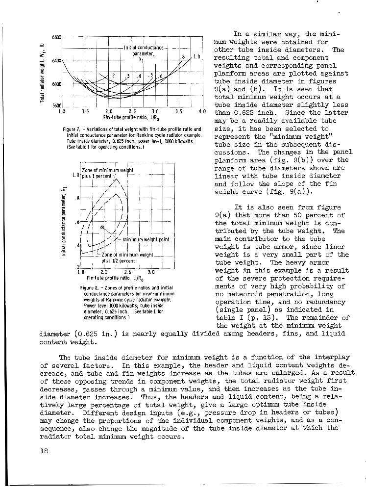
Physical charac te r i s t ics . - Since the computer program does not have a minimization procedure f o r radiator t o t a l weight, the minimum weights were determined graphically. 0.625-inch tube inside diameter is i l l u s t r a t ed as an example i n figure 7.
The graphical minimization of the t o t a l weight f o r a
The f a c t that values of i n i t i a l conductance parameter and fin-tube p ro f i l e r a t i o need not be precisely defined i n order to achieve near minimum radiator w e i g h t is more exp l i c i t l y shown for the same fixed tube diameter i n figure 8. Zones of minimum weight plus 1 percent and plus 1 /2 percent indicate a wide range of permissible p ro f i l e r a t i o s and i n i t i a l conductance pmaneters fo r t h i s example.
17
6800
1.0 1.5 2.0 2.5 3.0 3 . 5 4.0 Fin-tube profile ratio, !-/Ro
figure 7. - Variations of total weight with fin-tube profile ratio and initial conductance parameter for Rankine cycle radiator example. Tube inside diameter, 0.625 inch; power level, loo0 kilowatts. (See table I for operating conditions. )
I I I I l l ! I l Zoneof minimumweight I ~ ~ !
I I ' ,
In a similar way, the mini- mum weights were obtained for other tube inside diameters. The resul t ing t o t a l and component weights and corresponding panel planform areas a r e plot ted against tube inside diameter in figures 9(a) and (b ) . t o t a l minimum weight occurs a t a tube inside diameter s l i gh t ly l e s s than 0.625 inch. Since the l a t t e r may be a readi ly available tube size, it has been selected t o represent the "minimum weight" tube s i ze i n the subsequent dis- cussions. The changes i n the panel planform area ( f i g . 9 (b ) ) over the range of tube diameters shown a r e l inear with tube inside diameter and follow the slope of the f i n weight curve ( f i g . 9 ( a ) ) .
It is seen t h a t
plus U2 percent .2' 1 1 ! I l l
1.8 2.2 2.6 3.0 Fin-tube profile ratio, L/Ro
Figure 8. - Zones of profile ratios and initial conductance parameters for near-minimum weights of Rankine cycle radiator example. Power level loo0 kilowatts; tube inside diameter, 0.625 inch. (See table I for operating conditions. 1
diameter (0.625 in . ) is nearly equally divided among headers, f ins , and l iqu id content weight.
It is a l so seen from f igure 9(a) t ha t more than 50 percent of the t o t a l minimum weight is con- t r ibuted by the tube weight. The main contributor t o the tube weight is tube armor, since l i n e r weight is a very small par t of the tube weight. The heavy armor weight i n t h i s example is a r e s u l t of the severe protection require- ments of very high probabili ty of no meteoroid penetration, long operation time, and no redundancy (s ingle panel) as indicated i n table I (p. 15) . the weight a t the minimum weight
The remainder of
The tube inside diameter fo r minimum weight i s a function of the interplay In t h i s example, the header and l iqu id content weights de- of several factors.
crease, and tube and f i n weights increase as the tubes a re enlarged. A s a r e s u l t of these opposing trends i n component weights, the t o t a l radiator weight f irst decreases, passes through a minimum value, and then increases as the tube in- s ide diameter increases. Thus, the headers and l iqu id content, being a re la - t i ve ly large percentage of t o t a l weight, give a large optimum tube inside diameter. Different design inputs (e.g., pressure drop i n headers or tubes) may change the proportions of the individual component weights, and as a con- sequence, a l so change the magnitude of the tube inside diameter a t which the radiator t o t a l minimum weight occurs.
18

.
19

1.0
.8
.6 3
. 4 2
. 2 1 . 2 . 4 .6 . a 1.0
Tube inside diameter, Din, in.
Figure 10. - Variations of in i t ia l conductance parameter and f in-tube profi le rat io wi th tube inside diameters at min imum weights for Rankine cycle radiator example. Power level, loo0 kilowatts. (See table I for operat- ing conditions.)
Figure 11. - Schematic drawing of secondary cooling radiator.
A be t t e r understanding of various weight curves can be obtained from f i g - ures 9(c) t o ( e ) , where the quant i t ies t h a t describe the radiator geometry are p lo t ted against the tube inside diameter. It i s seen that, f o r small tube diame- ters, there a r e a large number of short tubes that y ie ld long and heavy headers with large inside diameters. Therefore, the aspect r a t i o tends t o be high, as shown i n f igure 9 ( f ) . are increased, the number of tubes be- comes smaller and the tubes longer. A s a r e su l t , the header length, diameter, and, consequently, the header weight, as wel l as aspect r a t i o decrease. r a t i o can a l so be controlled, i f the pressure drop i n the tubes can be varied independently. A s can be shown by com- bining equations (D7) , ( D 1 2 ) , and (D13) , the aspect r a t i o can be decreased i f the allowable tube pressure drop i s in- creased. variations i n f l u i d veloci ty a t the tube i n l e t t o be r e l a t ive ly small.
A s the diameters
The aspect
Figure 9(f) a l so shows the
Figure 10 shows the p ro f i l e r a t i o s and conductance parameters corresponding t o minimum weight a t each diameter f o r the range of tube inside diameters in- vestigated. These values were derived from curves similar t o those shown i n f igure 7 fo r each tube diameter. Fig- ure 10 indicates tha t , i n general, f o r the Rankine cycle radiator used as an
example, both L/Ro and hl increase with an increase i n tube s i ze . It should be emphasized that fo r each tube diameter there i s a considerable choice of e i ther L/Ro or A 1 without a s ign i f icant departure from minimum weight. For th i s par t iculzr example, the freedom of choice i n L/Ro and A 1 f o r a given percentage increase above minimum weight tended t o enlarge as the tube diameter increased. ure 8 for the 0.625-inch diameter.
The scope of t h i s f l e x i b i l i t y has been i l l u s t r a t e d i n f ig -
Secondary Cooling Radiator
A typ ica l application of the radiator i l l u s t r a t e d by t h i s example i s f o r
Secondary cooling secondary cooling, as shown schematically i n f igure 11. I n t h i s f igure, the components t o be cooled are ident i f ied as the heat source. radiators usually have low heat-rejection r a t e s w i t h small a x i a l temperature differences. The temperature l e v e l i s a l so comparatively low. The working
2 0

p: 0
c- 0-
c 620
1 I
0 .2 . 4 .6 . 8 1.0 Axial position along tube, ZlZ
Figure 12. - Variations of fluid and wall temperatures with tube length for secondary cooling radiator ex- ample. Heat-rejection rate, 20 Btu per second. (See table I for operating conditions. 1
f l u i d is generally a hydraulic l iquid, which may be selected not only f o r i ts heat-transfer properties but, i n some cases, f o r i t s lubricat ion capabi l i t i es . For th i s example, hydraulic l i qu id (e ther ET-378, ref. 24) was used as a working f l u i d because of i t s lubricat ion quali- t i e s . It has been considered fo r the secondary cooling and lubricat ion loop in the SNAP-8 system (information received *om A e r o jet/General Corp. ) . The heat- re ject ion ra te , 20 Btu per second, was a l so chosen approximately the same as f o r the SNAP-8 secondary radiator .
Both laminar and turbulent flows w e r e investigated. The results indicated that, a t lower tube inside diameters, the f low was fully developed laminar; how-
ever, a t l a rger diameters laminar, turbulent, o r m&ed flow-may be present as indicated by the Reynolds number. was assumed t o be uncertain when the Reynolds number f e l l between 2300 and 3000. The calculations i n this region were therefore made by using both sets of equa- t ions (laminar and turbulent 1. flow region cannot be predicted with certainty, the results may be of some in t e re s t .
For the purpose of this report , the flow
Although performance of the radiator i n this
Thermal charac te r i s t ics . - Much that was sa id about Rankine cycle radia- t o r s with NaK as the working f l u i d can be applied d i r ec t ly t o secondary cooling radiators . These w i l l be discussed for a secondary cooling radiator having a 0.125-inch tube inside diameter, an i n i t i a l conductance parameter of 0.5, and a fin-tube p ro f i l e r a t i o of 12. These values correspond t o a near m i n i m u m weight rad ia tor f o r the inputs con- sidered (table I, p. 15).
But there a re a l so some major differences.
A s shown in figure 12, the a x i a l f l u i d and tube w a l l temperatures are l i nea r between the i n l e t and the e x i t f o r the secondary cooling radiator em- ploying ether because the working f l u i d temperature differences are small. There are, however, large radial temperature differences between the l iqu id and the tube w a l l , a r e s u l t of t he r e l a t ive ly poor heat-transfer properties of the ether . The poor heat-transfer character is t ics were accepted because, i n t h i s example, the l i qu id is used also as a lubricant. l iquids w i l l y ie ld higher heat-transfer coefficients, and, consequently, i f such f lu ids are used i n secondary cooling radiators, smaller radial temperature differences (and, consequently, smaller surface area ] can be expected.
In general, less viscous
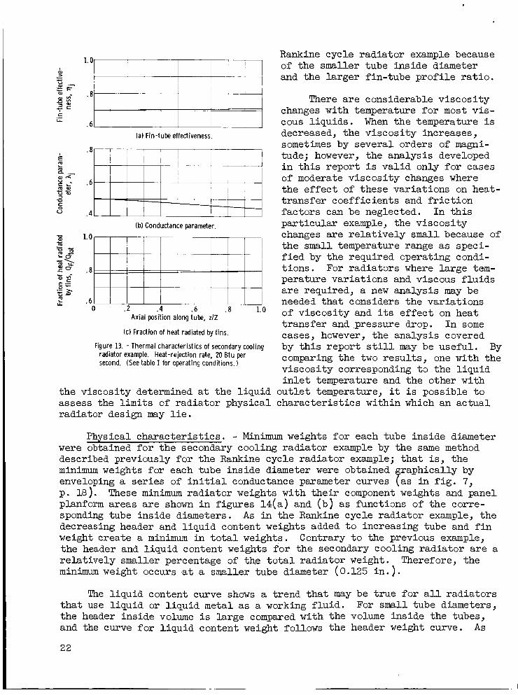
A s expected, conductance parameters, fin-tube effectiveness, and f i n heat- re jec t ion r a t e s are nearly l i nea r with a x i a l position, a s shown i n figure 13, and the magnitudes of a l l these var ia t ions are qui te small. effectiveness is somewhat lower than t h a t fo r the Rankine cycle rad ia tor exam- ple . On the other hand, the f rac t ion of heat radiated by the fins f o r the seccndary cooling radiator example is qui te high, much higher than that f o r the
The fin-tube
21
(a) Fin-tube effectiveness.
(b) Conductance parameter
Axial position along tube, zlZ
(c) Fraction of heat radiated by fins.
Figure 13. - Thermal characteristics of secondary cooling radiator example. Heat-rejection rate, 20 Btu per second. (See table I for operating conditions. 1
the viscosity determined a t the liquid
Rankine cycle radiator example because of the smaller tube inside diameter and the larger fin-tube p ro f i l e r a t i o .
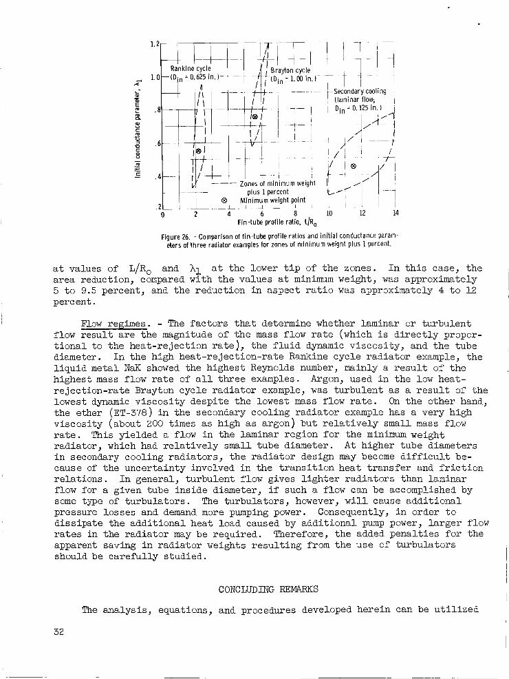
There a re considerable viscosi ty changes with temperature for most vis- cous l iquids . When the temperature is decreased, the viscosi ty increases, sometimes by several orders of magni- tude; however, the analysis developed i n t h i s report i s va l id only f o r cases of moderate viscosi ty changes where the e f fec t of these variations on heat- t ransfer coefficients and f r i c t i o n factors can be neglected. In t h i s par t icular example, the viscosi ty changes are r e l a t ive ly small because of the small temperature range a s speci- f i e d by the required operating condi- t ions. For radiators where large tem- perature variations and viscous f lu ids a r e required, a new analysis may be needed tha t considers the variations of viscosi ty and i ts e f fec t on heat t ransfer and pressure drop. In some cases, however, the analysis covered by t h i s report s t i l l may be useful. By comparing the two resu l t s , one with the viscosi ty corresponding t o the l iquid i n l e t temperature and the other with
out le t temperature, it i s possible t o assess the l i m i t s of radiator physical character is t ics within which an actual radiator design may l i e .
Physical character is t ics . - Minimum weights fo r each tube inside diameter were obtained fo r the secondary cooling radiator example by the same method described previously f o r the Rankine cycle radiator example; t ha t is, the minimum weights for each tube inside diameter were obtained graphically by enveloping a ser ies of i n i t i a l conductance parameter curves (as i n f i g . 7, p. 18). These minimum radiator weights with the i r component weights and panel planform areas a re shown i n figures 14(a) and (b ) as functions of the corre- sponding tube inside diameters. A s i n the Rankine cycle radiator example, the decreasing header and l iquid content weights added t o increasing tube and f i n weight create a minimum in t o t a l weights. the header and l iquid content weights f o r the secondary cooling radiator a r e a re la t ively smaller percentage of the t o t a l radiator weight. Therefore, the minimum weight occurs .at a smaller tube diameter (0.125 in . 1.
Contrary t o the previous example,
The l iquid content curve shows a trend tha t may be t rue for a l l radiators For small tube diameters, t ha t use l iquid or l iquid metal as a working f lu id .
the header inside volume is large compared with the volume inside the tubes, and the curve fo r l iqu id content weight follows the header weight curve. A s
22

A
m -
I e
3
23

.
ci
m- a
al L m
L 0
9-
420
?40
260
180
9 100
Tube inside diameter, Din, in.
Figure 15. - Comparison of radiator total weights and panel planform areas for laminar and turbulent flows with tube inside diameter for secondary cooling radiator example. Heat-rejection rate, 20 B tu per second. (See table I for operating conditions. 1
source
14 t (a) Schematic diagram.
2 al L 3 c m
k 5 c
4
L
Entropy
(b) Thermodynamic diagram.
Figure 16. - Brayton cycle diagrams.
980
900
820 OL 0
I--
3 740 2-
5 m L al n
c 660
580
Hx
Figure 17. - Variations of f lu id and wall temperatures wi th tube length for Brayton cycle radiator example. Power level, 8 kilowatts. (See table I for operating conditions. )
24

the tube inside diameters increase, the header volume decreases, and the curve fo r l iqu id content weight tends t o follow the tube weight curve.
The quant i t ies that describe radiator and header geometry f o r laminar flow conditions are plot ted against tube inside diameter i n figure 14(c) t o (e) (p. 23) . Fluid inlet velocity and aspect r a t io a re shown i n figure 14( f ) . The same general trends prevai l w i t h tube inside diameter for the secondary cooling radiator example as f o r the Rankine cycle radiator example. Figure 14(g) shows fin-tube p ro f i l e r a t io s and i n i t i a l f i n conductance parameters fo r m i n i m u m weight f o r each tube inside diameter. departures from these values can be tolerated with a very small increase in radiator weight.
As indicated previously, however, Large
Figure 15 (p. 24) compares the t o t a l weights and panel planform areas ob- tained from the Laminar flow equations with those obtained from the turbulent flow equations. i f , a t larger tube diameters, early t ransi t ion t o fully developed turbulent flow can be promoted.
It is seen that w e i g h t and area can be considerably reduced
Brayton Cycle Radiator
The radiator used for t h i s example typically performs the service required from the heat-rejection uni t i n a Brayton cycle power system shown schemati- ca l ly i n figure 16. The heat-rejection r a t e is 28.3 Btu per second, and the working f l u i d is argon. The physical and thermal properties of argon are taken from reference 25. a l l cases investigated fo r t h i s example, the flow was fully turbulent.
The system generates several kilowatts of e l ec t r i c i ty .
For
Thermal character is t ics . - The gas temperature variations, along with the temperature of the w a l l , a r e shown in figure 1 7 . The example selected had a - -
1-inch tube diameter, a fin-tube prof i le r a t i o of 6, and an i n i t i a l conductance parameter of 1. t i v e value a t the tube i n l e t . fourth power of the wall temperature, i s greatest a t the tube i n l e t and accounts f o r the rapid decrease of temperature in t h i s region. temperature difference between the wall and the gas is evidence of the rela- t i v e l y low convective heat-transfer coefficient of the gas. it w a s assumed that the convective heat-transfer coeff ic ient between the gas and the w a l l w a s constant over the ent i re tube length. heat-rejection r a t e decreasing as the gas proceeds along the tube, the temper- a ture difference between the f l u i d and the wall a l so decreases (eq. (3)) .
For both temperature curves, the slope has the la rges t nega- The heat-rejection ra te , being re la ted t o the
The Large
In the analysis,
As a resu l t , w i t h the
Figure 18 shows the changes in the conductance parameter, fin-tube effec- tiveness, and fract ion of heat radiated by the f i n s as a f h c t i o n of axial posit ion along the tube length. It is seen that the pr incipal character is t ics of these parameters a re large decreases of conductance parameter along the tube length (by -70 percent) and the large amount of heat re jected by the fins (-75 percent ) .
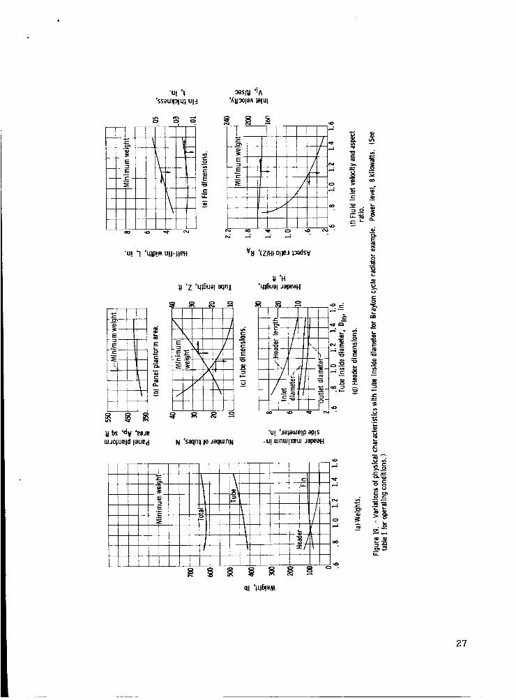
Physical character is t ics . - In order t o generate the minimum weight enve- lope curve fo r the Brayton cycle radiator, which has re l a t ive ly f e w tubes, a
25

.- x i al c
E z al U c
U z 'p c 0 u
m c
(a) Conductance parameter.
1.0 I
1 I I '
(b) Fin-tube effectiveness.
0 . 2 . 4 .6 .8 1.0 Axial position along tube, zlZ
(c) Fraction of heat radiated by fins.
figure 18. - Thermal characteristics of Brayton cycle radiator example. Power level, 8 kilowatts. (See table I for operating conditions. )
more elaborate procedure had t o be employed than tha t used fo r the Rankine and secondary cooling radiator exam- ples . The method i s discussed i n appendix G. The minimum weight thus obtained fo r each tube inside diameter i s shown i n f igure 19(a) . Since the f l u i d content weight for i ne r t gases i s very small, it is not shown. A s i n the previous example, the decreasing header weights a r e opposing the in- creasing tube and f i n weights, thus creating a minimum i n combined weights a t about a 1.00-inch tube inside diame- t e r . The headers again a re r e l a t ive ly heavy s o tha t minimum weight occurs a t a large diameter. Compared with the Rankine cycle and secondary cooling radiator examples, the t o t a l minimum weight of the Brayton cycle radiator i s l e s s sensi t ive t o diameter changes over a wider range. The e f fec t of tube diameters on panel planform area i s a l so small for the values of diameter covered.
Figures 19(c) t o ( e ) shows some fur ther quantit ies t ha t describe the radiator and headers as functions of the tube inside diameter. A s the diameter increases, the tube length, f i n width, and f i n thickness ( a f t e r undergoing a s l i gh t decrease) increase. For the smaller tube diameters, the combination of a large number of
shorter tubes leads t o a radiator panel with a large aspect r a t io , as shown i n figure 19(f). The same f igure a l so i l l u s t r a t e s the veloci t ies a t the tube i n l e t as a function of 'tube inside diameter. with their sonic veloci t ies , and the e f f ec t of turning losses a t tube-header junctions i s expected t o be- small.
The veloci t ies a re small compared
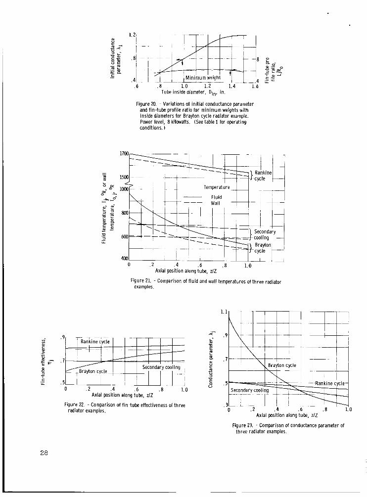
Figure 2 0 shows the fin-tube prof i le r a t i o and the i n i t i a l conductance parameters corresponding t o minimum t o t a l weights f o r each tube inside diame- t e r . The i n i t i a l conductance parameter varies substant ia l ly with tube inside diameter, but the fin-tube prof i le r a t i o i s essent ia l ly constant. A s i n pre- vious examples, w i d e choices of L/Ro and A 1 a re available t o maintain a near minimum weight design.
Comparison of Characterist ics
The three examples considered i n the previous sections covered a wide
26
27
28
.6 . 8 1.0 1.2 1.4 1.6 Tube inside diameter, Din, in.
Figure 20. - Variations of in i t ia l conductance parameter and fin-tube profile rat io for minimum weights wi th inside diameters for Brayton cycle radiator example. Power level, 8 kilowatts. (See table I for operating conditions. )
\ 800 ' 600 --+ =-=
400 0 . 2 4 .6 .8 1.0
Axial position along tube, zlZ
Figure 21. - Comparison of f lu id and wall temperatures of three radiator examples
.9
. 7
. 5 0 . 2 .4 .6 . 8 1.0
Axial position along tube, zlZ
Figure 22 - Comparison of fin-tube effectiveness of three radiator examples.
Axial position along tube, zlZ
Figure 23. - Comparison of conductance parameter of th ree radiator examples.

.a
.4
~~Secondarycool ing ~ 1 1 , , , , , ! , I
I ~ -+-A-+ Rankine cycle I i l I ' 1 1
I I
range of radiator heat-re jection rates . Corresponding t o these heat- rejection ra tes , the maximum tempera- tures of the working f lu ids ranged f'rom about 700' t o 1700' R. quently, each type of these sensible- heat radiators exhibited different thermal and physical character is t ics . Although the resu l t s f o r the examples considered may not necessarily be precisely representative f o r a l l radi-
Conse-
a tors i n each c lass considered, a comparison of the resu l tan t character is t ics of the examples may nevertheless prove t o be of i n t e re s t .
Thermal character is t ics . - Sensible-heat thermal radiators are d is t in - guished fo r t he i r a x i a l variations not only of the f l u i d and tube wall tempera- tures ( f ig . 2 1 ) but a l so of fin-tube effectiveness, conductance parameters, and the fract ion of heat radiated from the f ins . longitudinal temperature difference determines the prof i le of the properties that a re temperature dependent. f o r near minimum weight radiators i n each class a re given i n figures 2 1 t o 24.
Therefore, the magnitude of the
Comparisons of these thermal character is t ics
When the temperature difference is relat ively small and the tube length re la t ive ly large, as in the secondary cooling and the Rankine cycle radiator examples, temperature, effectiveness, conductance parameter, and f i n heat- re ject ion r a t i o s tend t o approach a s t ra ight- l ine re la t ion with the tube length. When the ax ia l temperature difference is large, as i n the Brayton cycle radia- t o r example, the temperature variations are no longer l inear w i t h heat-rejection r a t e but are greatest a t the tube i n l e t .
Iarge axial temperature variations give r i s e a l so t o large variations in fin-tube effectiveness ( f ig . 22) and conductance parameter ( f ig . 23). The f i n heat-rejection r a t i o is l e s s affected by ax ia l temperature difference ( f i g . 24). The l eve l of t h i s r a t i o depends mainly on The secondary cooling radia- t o r example has the highest fin-tube prof i le and f i n heat-rejection ra t io ; the Rankine cycle radiator example has the lowest.
L/Ro.
In the comparison of f l u i d and wall temperatures shown i n figure 21, the temperature difference is a function of the convective heat-transfer coeffi- c ient as w e l l as the local heat-rejection ra te ; when the local heat-rejection r a t e varies appreciably with tube length, a s i n the Brayton cycle radiator example, the r a d i a l temperature difference a l s o varies appreciably. On the other hand, with heat-rejection ra tes f o r the Rankine cycle and secondaq cooling radiator examples nearly constant, the wall temperatures almost pa ra l l e l the f l u i d temperatures. Argon and ether had the poorest heat-transfer properties of the three examples, and they experienced the la rges t rad ia l tem- perature drops. As NaK is a much be t te r heat-transfer f lu id , it had re la t ive ly smaller r ad ia l temperature differences.
Minimum weight radiators . - The principal character is t ics of the three radiators a t minimum weight a re given i n table 11.
29

TABU3 11. - CHARACTFKCSTICS OF MINIMUM WEIGHT RADIATORS
436 7 5772 2.17 0.55
3.27 228 000
10.8 993 13 4 17.4 0.625 1.76 0.121
Parameters
20 167 11.5 0.45
2.48 745 3.75 317 64
11.3 0.1125 2.45 0.007
Symbols
Heat-rejection rate Total weight Fin-tube profile ra t ic I n i t i a l conductance
Aspect ra t io (H/Z) Reynolds number Fluid inlet velocity Panel planform area Number of tubes Single tube length Inside tube diameter Half-fin width Fin thickness
parameter
QR Wr
L/R, A 1
AR Re V i AP
Din
N Z
L t
~~~~ ~
Radiator example
Rankine Secondary cycle cooling
(laminar 7 f low}
Bray t or cycle
28.3 615 5.6 0.8
0.71 18 780
17 4 393 22
23.5 1.0 3.88 0.018
Comparison of the three examples shows tha t each had a unique s e t of - geometric parameters: fin-tube prof i le r a t io , f i n conductance parameter a t the radiator entrance, and tube inside diameter for a minimum weight radiator . A s mentioned ea r l i e r , the mininum weights were determined graphically, and there- fore they may not necessarily represent precisely the actual values.
There a re several factors responsible f o r the f ac t t ha t the minimum weight occurred a t the par t icular values l i s t e d i n table I1 (e.g. , magnitudes of heat- rejection ra tes , mass flow ra tes , temperature level, pressure l eve l and allow- able pressure drop, and radiator mater ia ls) . Therefore, it may not be possible analytically t o predict a s e t of desired parameters beforehand t h a t w i l l automatically, without fur ther parametric studies, yield the minimum weight radiators.
For the examples compared i n tab le 11, the absolute minimum weight of the secondary cooling radiator example occurred a t the lowest tube inside diameter of a l l three examples. lowest volumetric flow i n each tube. having the largest volumetric flow r a t e per tube, yielded the absolute m i n i m u m weight a t the largest tube inside diameter.
The secondary cooling radiator example had a l so the The Brayton cycle radiator example,
Another noteworthy character is t ic of these m i n i m u m weight radiators i s the
L/Ro, while the Rankine cycle magnitude of fin-tube prof i le r a t io s . has the lowest temperature l eve l and the la rges t radiator example has the la rges t temperature l eve l and the smallest a l l three examples.
The secondary cooling radiator example
of L/Ro
30

- x i W W c
f L m P
w V c
u 3 V c 0 V
m
c
m c
- - - c -
(a) Fin-tube profile ratio.
1.2
. 8
.4
0 .4 . 8 1.2 1.6 Tube inside diameter, Din, in.
(b) Initial conductance parameter.
Figure 25. - Comparison of initial conduc- tance parameter and fin-tube profile ratio at minimum weight for three radi- ator examples.
For the three radiator examples, it appeared that the i n i t i a l conductance parame- t e r a t minimum w e i g h t increased with tube in- side diameter. These trends and the var ia t ions of fin-tube p r o f i l e r a t i o a t m i n i m u m w e i g h t f o r each diameter and absolute minimum weight are flrther i l l u s t r a t ed i n figure 25 f o r the exam- p les considered.
Design trade-offs. - It is seen from com- parison of t o t a l weight and panel planform area curves ( f igs . 9 (a) and (b) , p. 19, Rankine cycle rad ia tor example, 14(a) and (b), p. 23, secondary cooling radiator example, and 19(a) and (b), p. 27, Brayton cycle radiator example) that t o t a l weight f i rs t decreases with in- creasing tube inside diameter u n t i l the minimum points are reached, w h i l e panel planform area i n a l l cases continues t o increase w i t h in- creasing tube inside diameter. This suggests that the use of diameters smaller than those fo r minimum weight affords a possible area- weight trade-off. For example, going t o smaller tube inside diameters and increasing the w e i g h t by only approximately 1 percent reduces the panel planform area approximately from 4 t o 8 percent, the la rges t reduc'tion occurring f o r the Rankine cycle radiator example and the smallest f o r the Brayton cycle radiator exam- ple . This area-weight trade-off, however, causes an increase in aspect r a t i o from 50 t o 65 percent.
The aspect r a t i o can be reduced, and a t the same time similar area-weight trade-offs can be accomplished, a s i n the previous case, by using smaller values of LyR0 and A 1 than those corresponding t o minimum weights f o r t he par t icu lar example instead of smaller tube inside diameters. Furthermore, the aspect r a t i o can a l so be controlled by varying the allowable pressure drop as w a s mentioned previously. dividing one panel i n t o a number of smaller panels. panels, the aspect r a t i o fo r a Brayton cycle radiator example can be reduced from 0.76 t o 0.38. I n this example, the panels w e r e imagined t o be arranged around a cen t r a l column, a l l i n one plane, so t h a t no mutual radiat ion or occlusion from meteoroids need be considered.
Another means of reducing the aspect r a t i o is by For example, by using two
It w a s observed earlier ( f ig . 8, p. 18) that the values of L/Ro and AI can have wide var ia t ions with only small affects on w e i g h t . This is fur ther i l l u s t r a t e d i n f igure 26, which shows zones of m i n i m u m weight plus 1 percent as a function of L/Ro and A 1 f o r a l l three examples, each fo r the tube inside diameter t h a t gave the smallest t o t a l w e i g h t . I n addition, t he panel planform area var ies d i r ec t ly with L/Ro and A 1 as w i t h Din. This -lies that the lowest panel planform area within the zones shown i n f igure 26 can be expected
31
Fin-tube profile ratio, L/Ro
Figure 26. - Comparison of f in-tube profile ratios and in i t ia l conductance param- eters of three radiator examples for zones of min imum weight plus 1 percent.
a t values of L/Ro and A 1 a t the lower t i p of the zones. I n t h i s case, the area reduction, compared with the values a t minimum weight, was approximately 5 t o 9.5 percent, and the reduction i n aspect r a t i o was approximately 4 t o 1 2 percent.
I Flow regimes. - The factors that determine whether laminar or turbulent flow resu l t a r e the magnitude of the mass flow r a t e (which i s d i r ec t ly propor- t i ona l t o the heat-rejection r a t e ) , the f l u i d dynamic viscosi ty , and the tube diameter. I n the high heat-rejection-rate Rankine cycle radiator example, the l iqu id metal NaK showed the highest Reynolds number, mainly a r e s u l t of the highest mass f l o w r a t e of a l l three examples. Argon, used i n the low heat- rejection-rate Brayton cycle radiator example, was turbulent as a r e s u l t of the lowes t dynamic viscosi ty despite the lowest mass flow rate. On t he other hand, the ether (ET-378) i n the secondary cooling radiator example has a very high viscosity (about 200 times as high as argon) but r e l a t ive ly small mass f low r a t e . radiator, which had r e l a t ive ly small tube diameter. i n secondary cooling radiators , the radiator design may become d i f f i c u l t be- cause of the uncertainty involved i n the t rans i t ion heat t ransfer and f r i c t i o n relat ions. I n general, turbulent flow gives l i gh te r radiators than laminar flow for a given tube inside diameter, if such a flow can be accomplished by some type of turbulators. The turbulators, however, w i l l cause addi t ional pressure losses and demand more pumping power. Consequently, i n order t o dissipate the addi t ional heat load caused by addi t ional pump power, l a rger f low r a t e s in the radiator may be required. Therefore, the added penalties fo r the apparent saving i n radiator weights resul t ing from the use of turbulators should be careftilly studied.
This yielded a flow i n the laminar region fo r the minimum weight A t higher tube diameters
CONCLUDING REMAFXS
The analysis, equations, and procedures developed herein can be u t i l i z e d
32

for determining design configurations or parametric studies of f la t -p la te central-fin-tube sensible-heat radiators for a w i d e range of power system applications. cycle, secondary cooling, and Brayton cycle radiators showed that unique condi- t ions can be defined for minimum w e i g h t configurations and that a wide range
w e i g h t . character is t ics that were a t t r ibu tab le t o the par t icular range of heat- re ject ion r a t e , temperature level, temperature difference, and type of working f luid. However, a m o r e extensive ser ies of parametric studies covering a wide range of input pmameters w i l l be required to define the character is t ics of 'these classes of radiators bet ter .
Sample calculations conducted f o r s ingle representative Rankine 1 I of radiator geometry can be obtained w i t h re la t ively small variation in t o t a l
Each radiator example revealed somewhat d i f fe ren t thermal and physical
I
~ ' L e w i s Research Center, National Aeronautics and Space Administration,
Cleveland, Ohio, February 15, 1965. , , I
33

APPENDIX A
SYMBOLS
A
a
E
C,C'
C
cP
D
F
FO
f
G
h
k
kW
L
m
N
NC
n
area, sq f t
f i n i t e p la te thickness and spa l l ing fac tor
occlusion fac tor
constants of integrat ion
sonic velocity, f t / s ec
constant pressure specif ic heat, Btu/( l b ) ( %)
diameter, f t
angle factor
integrated f r i c t i o n parameter
f r i c t ion coeff ic ient
mass velocity, lb/( see)( sq f t ]
conversion factor , 32.2 ( f t /sec2 )( l b mass/lb force)
header length, f t
heat-transfer coeff ic ient , Btu/( sec) ( sq f t ) ( %)
location
constant
thermal conductivity of tube and f i n material, Btu/(hr)(f t ) ( %)
thermal conductivity of working f lu id , Btu/( sec) ( ft)( %)
half-fin width
mass flow ra te , lb/sec
number of tubes
blackbody conductance parameter, dimensionless
number of elemental isothermal strips
34

pressure, lb/sq f t abs
overal l probability of no meteoroid penetration
Prandtl number
t o t a l number of ident ica l panels
probabili ty of no meteoroid penetration of a segment
number of ident ica l panels surviving
heat-rejection ra te , B t u / h r or Btu/sec
gas constant, f t - lb / ( lb) (%)
aspect r a t i o
Reynolds number
tube outside radius, f t
index of summation
absolute temperature, ?R
f i n thickness, f t
overal l heat-transfer coefficient, Btu/(hr)( sq f t ) ( %)
velocity, f t / s ec
average meteoroid velocity, 98 400 f t /sec
weight, l b
distance from base surface along f i n width, dimensionless
distance along header length, f t
tube length, f t
distance i n direction of f lu id flow i n tubes, f t
constant i n meteoroid mass distribution, 0.53x10'10 gmp/( sq f t ) (day)
constant i n meteoroid mass distribution, 1.34
w a l l thickness, f t
hemispherical emissivity
35
- € apparent emissivity
rl fin-tube effectiveness
e temperature r a t i o , dimensionless
A conductance parameter, dimensionless
CL viscosity, lb/( f t ) ( sec)
P density, lb/cu f t
(5
a- mission time, days
Subscripts :
Stefan-Boltzmann constant, 1.713X10'9 Btu/( sq f t ) (h r ) ( ?R4)
a
C
C
e
F
f
H
I
i
i n
j
L
n
0
P
P
R
36
armor
c onve c t ion
l i n e r
exposed
f i n
exi t
header
l iquid content
i n l e t
inside
a t location j ; radiator element
l iquid
l a s t element
outside or ou t l e t
pane 1
part i c l e
radiated

r
S
S
sc
t
t o t
V
VaP
W
z - X
1
2
rad ia tor
sensible
S i n k
subcooled
tube
t o t a l
vulnerable
vapor
working f l u i d
a t locat ion Z - a t locat ion x
f irst element
second element
37

APpE;NDIX B
ARMOR THICKNESS AND VUIlEWBm AREA
The tube armor thickness 6, has t o be su f f i c i en t t o assure the desired The probabili ty of no meteoroid puncture during the prescribed mission time.
armor thickness required t o give t h i s protection w a s computed by the following formula taken from reference 1 7
where
0.44 g/cc
V 98 400 f t / sec pP -
j3 1.34
a 0.53X10 g /(sq f t ) ( d a y ) (Whipple value without Earth shielding) -10 p
The coefficient a spal l ing factor , and was assigned a value of 1.75 ( ref . 1 7 ) . The vulnerable area A, i n equation ( B l ) is a product of occlusion fac tor F and exposed area A,:
i n equation (Bl) stands fo r f i n i t e p la te thickness and
= FAe
The factor discrete surfaces. I n t h i s analysis, C was taken t o be equal t o 1; that is, no shielding w a s assumed.
represents reduction i n - armor thickness due t o shielding of
The exposed area A, is considered t o consist of the tube outside surface area A t and the header outside surface area A The elemental tube outside area a t location j i s obtained from equations Ti) and (3) as:
The t o t a l tube outside area i s obtained by summing equation (B2) over the index j :
The tube outside diameter Do i s a function of tube inside diameter D i n , tube armor thickness €ia, and l ine r thickness 6,:
38

Do = D i n + 26a + 26,
The tube inside diameter w a s an input for this analysis. quant i t ies that is varied parametrically t o study the e f fec t on radiator de- sign, panel planform area, and w e i g h t .
It is one of the
The thickness of the l i n e r was scheduled with inside diameter by the following r e l a t ion
6, = 0.04 Din
with a m i n i m a n thickness of 0.015 inch.
A t t h i s point i n the program the header area i s unknown. Since header area i s taken as a pa r t of vulnerable area, an estimated value for the t o t a l vulnerable area must be used i n i t i a l l y i n equation (Bl) when the header area is nonnegligible. Equations fo r determining header area aze given i n appendix E. An i t e r a t ion is incorporated into the program t o determine actual t o t a l vulner- able area when the header area is significant.
39

APPENDIX C
PRESSURE DROP I N RADIATOR TUBES
The change i n pressure due t o the flow of f l u i d i n the rad ia tor tubes can be divided into three components: the lo s s i n pressure when the f l u i d is turned from the header in to the tube and from the tube i n t o the header; the momentum pressure r ise associated w i t h the density and veloci ty changes a s t he f l u i d f lows down the tube; and the pressure l o s s due t o f r i c t i o n . analysis the f i r s t two components have been ignored, and the calculated pres- sure drop w a s based on the pipe f r i c t i o n only. because the ve loc i t ies of s ingle phase f lu ids i n the tubes are r e l a t ive ly small, and it has been f i r t h e r assumed that the header-tube jo in t s are smooth and rounded. Under such conditions, the turning losses amount t o l e s s than one dynamic head a t the tube entrance, whereas the f r i c t i o n pressure l o s s may be several dynamic heads. With r e l a t ive ly small changes i n veloci ty i n the tubes f o r the gas working f lu id , and no change fo r the l i qu id working f lu id , the momentum change is considerably less than one dynamic head and can a l so be ignored. Furthermore, the two pressure changes a re of opposite sign and tend t o cancel each other. Should circumstances arise so tha t it is desirable t o consider turning losses, t h i s can be done merely by reducing the allowable pressure drop i n the tubes.
In t h i s
The turning los s w a s ignored
To obtain the f r i c t i o n pressure drop i n a radiator tube it i s necessary t o integrate the Fanning equation
V2 dz dP = -2fp - - g Din
over the e n t i r e tube length. In t h i s analysis, f has been assumed constant along the tube and i s based on the Reynolds number i n the tube. coefficient
The f r i c t i o n f i n equation ( C 1 ) i s evaluated fo r turbulent flow ( R e 2 3000) a s
0.046 f = -
Reo *
and f o r laminar flow (Re 1. 2300) as
16 f = - Re
Two f r i c t ion factors and two pressure drops a re computed f o r 2300 < R e < 3000, from the laminar and turbulent flow equations, when comparative r e su l t s i n t h i s t rans i t iona l region a r e required. dependent on the nature of the working f l u i d .
The integrat ion of the Fanning equation i s
Liquid Working Fluid
I f t he working f lu id i s a l iquid, the integrat ion of equation (Cl)
40

presents no problem because the variation of both the l iquid density and flow velocity with temperature is comparatively small. considered constant over the ent i re tube length (constant diameter tubes) and evaluated a t the teaperatwe of tube midpoint. equation becomes
The l iquid density can be
The integrated f o r m of the
Gas Working Fluid
When the f l u i d i n the radiator tube is a gas, the problem of computing the pressure drop becomes more d i f f i c u l t because the assumption o f constant density and velocity, i n general, can no longer be applied. The extraction of heat from the gas through the convection-conduction-radiation process increases the density of the gas along the tube length t o a much greater extent than for l iquids. Equation ( C l ) can be rewrit ten i n terms of gas temperatures
G2 RT dP = -2f - .+ dz
@in
2 where G = 4&/fiDinN. r e la t ion between temperature and tube position can be determined.
Equation (C4) can be integrated as soon as an analyt ical
Such a re la t ion i n d i f f e ren t i a l form is available by equating the r igh t sides of equations (1) and ( 3 ) , or equations (1) and (8):
This re la t ion is not very convenient because, a t the point in the coaputer program where it is required, Do, N, and are a l l unknowns. U,
I n order t o avoid the use of another equation, namely equation ( C 5 ) , which involved quant i t ies that had t o be determined by an i t e r a t ive process, it w a s assumed for convenience that the r a t e of change of f l u i d temperature with tube length followed the re la t ion
dTj = K(TQ - T4)dz s (csa)
s o t ha t
41
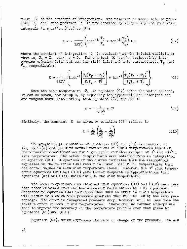
where C i s the constant of integration. The re la t ion between f l u i d tempera- tu re T j and tube posit ion z is now obtained by integrating the indefini te integrals i n equation (C6b) t o give
where the constant of integration tha t i s , T j = T i when z = 0. The constant K can be evaluated by inte- grating equation (C6a) between the f l u i d i n l e t and ex i t temperatures, Ti Tf, respectively:
C is evaluated a t the i n i t i a l conditions;
and
When the sink temperature Ts i n equation ( C 7 ) takes the value of zero, it can be shown, for example, by expanding the hyperbolic arc cotangent and arc tangent terms into ser ies , tha t equation ( C 7 ) reduces t o
Similarly, the constant K as given by equation ( C 8 ) reduces t o
= ik ($ - $) The graphical presentation of equations ( C 7 ) and ((29) i s compared i n
figures 27(a) and ( b ) with ac tua l variations of f l u i d temperatures based on heat-transfer considerations f o r a gas cycle radiator example of 0' and 400° R sink temperatures. of equation (C5). expressed i n the re la t ion ( C 6 ) r e s u l t i n lower loca l f l u i d temperatures than the actual values i n both sink temperature cases. a ture equations ( C 9 ) and (C10) gave be t te r temperature approximations than equations (C7) and (C8), which include the sink temperature.
The ac tua l temperatures were obtained from an integration Comparison of the curves indicates that the assumptions
However, the 0' sink temper-
The loca l temperatures as obtained from equations ( C 9 ) and ( C 1 0 ) were l e s s than those obtained from the heat-transfer calculations by 0 t o 5 percent. Reference t o equation (C4) indicates t ha t such a3 error i n f l u i d temperature w i l l r e su l t i n a calculated pressure gradient that w i l l be low by the same per- centage. The error i n integrated pressure drop, however, w i l l be l e s s than the maximum error in loca l f l u i d temperatures. Therefore, no further attempt was made t o improve the accuracy of the temperature prof i le over t ha t given by equations ( C 9 ) and ( C 1 0 ) . I
Equation (C4) , which expresses the r a t e of change of the pressure, can now
42
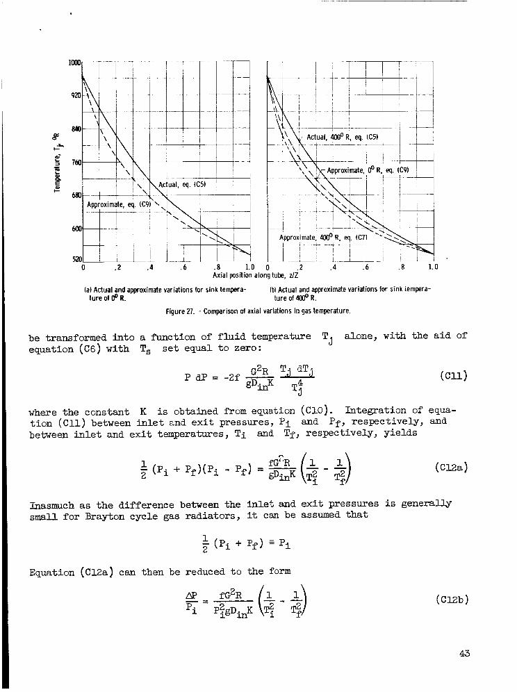
Axial position along tube, ZlZ
(a) Actual and approximate variations for sink tempera- (b) Actual and approximate variations for sink tempera- ture of 8 R. ture of & R.
Figure 27. - Comparison of axial variations in gas temperature.
alone, with the a i d of Tj be transformed in to a function of f l u i d temperature equation (C6) with Ts s e t equal t o zero:
where the constant K is obtained from equation (C10). Integration of equa- t ion ( C 1 1 ) between i n l e t and e x i t pressures, P i between i n l e t and e x i t temperatures, T i and Tf, respectively, yields
and Pf, respectively, and
Inasmuch as t h e difference between the inlet and e x i t pressures is genera- small f o r Brayton cycle gas radiators , it can be assumed that
1 - (pi + Pf) E P i 2
Equation ( C l Z a ) can then be reduced t o the form
- - - 2

APPENDIX D
GEOMETRY OF TUBES AND FINS
The heat-transfer analysis and the armor-thickness calculations i n appen- dix B have established a l l necessary re la t ions t o describe the geometric de- t a i l s of the rad ia tor panel tubes and f ins , with the exception of the tube length Z . 6a, tube outside diameter Do, and the l i n e r thickness 6,, respectively. The h a l f - f i n width is avai lable from the equation
Thus, equations ( B l ) , (B4), and (B5) gave the tube armor thickness
L L = - 0.5 Do RO
and t h e f i n thickness follows from equation (12) as
2 a ~ T 2 .L2
kFh j t =
Tube Length i n Turbulent Flow
For i n e r t gases i n turbulent f low, the length of a s ingle tube Z i s ob- tained from equation (ClZb) :
With the use of the def ini t ions
and
the constant K obtained from equation (ClO), and the f r i c t i o n coeff ic ient f from equation ( C Z a ) , equation (C12b) then takes the form
where
44
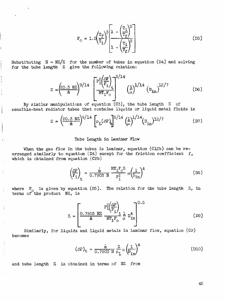
FO = l..(g - al 1 - ($7
Substi tuting N = NZ/Z f o r the number of tubes i n equation (D4) and solving for the tube length Z give the following relation:
1/14 (D6 1
By similar manipulations of equation (C3), the tube length Z of sensible-heat radiator tubes tha t contains liquids or l iquid metal f lu ids is
Tube Length i n Iaminar Flow
When the gas flow i n the tubes is laminar, equation (Cl2b) can be re- arranged s imilar ly t o equation (D4) except for the f r i c t i o n coefficient which is obtained from equation (C2b)
f ,
m RTiFoZ 4 0.7903 N p:
where Fo is given by equation (D5). The relat ion f o r the tube length Z, i n terms of the product NZ, is
0.5 2 m
(D9)
Similarly, fo r l iquids and l iquid metals i n laminar flow, equation ( ~ 3 ) bec ome s
and tube length Z i s obtained i n terms of NZ from
45

Number of Tubes
With tube length Z determined by equations (D6), (D7), (D9), o r (Dll), depending on the phase of the working f l u i d (gaseous or l i qu id ) and flow regime (turbulent or laminar), the number of tubes N can be calculated from the product NZ (eq. (B3)). In t h i s program, f r ac t iona l numbers of tubes were
I rounded o f f t o the next higher integers .
Panel Area and Aspect Ratio
The panel planform area, which i s the projected area of the f i n s and tubes, is given by
The aspect r a t io , defined as the r a t i o of the panel width t o the tube length, can be obtained from the preceding equation f o r panel area and the appropriate equation f o r tube length or ( D 1 1 ) t o give
Z, t h a t is, equation (D6), (D7), (D9),
46

A comprehensive study of f la t sensible-heat space radiators requires the inclusion of a design fo r the i n l e t and out le t headers. of the equations that a f f ec t header geometry, shape, vulnerable area, and w e i g h t is given i n t h i s section. I n the analysis, it is assumed that the headers are joined d i rec t ly t o the tubes i n the same plane as the tubes. Accordingly, they a re exposed t o meteoroid impact and a re protected with the sane armor thickness as the tubes. Because the shape and s ize of the headers depend on the phase of the f luid, it wits necessary t o consider the header de- sign for the two types of f l u i d separately. Mass flow ra t e , pressure level, pressure drop, temperature level, and header length were t reated as independent variables f o r the header design i n a l l cases. Radiation from the outer sur- faces of the headers was assumed negligible. assumption is discussed l a t e r .
A detailed development
The jus t i f ica t ion f o r t h i s
Gas Headers
The header shape and arrangement employed f o r a single-panel radiator that uses iner t gas as a working f l u i d is shown i n figure l ( a ) . in to the i n l e t header a t one s ide of the radiator, is dis t r ibuted among the panel tubes, and leaves the out le t header a t the opposite side of the radiator panel. This type of design tends t o approach an equal pressure drop across each tube, thereby promoting uniform flow distribution and similar velocity prof i les i n both headers.
The gas is taken
D i a m e t e r and pressure drop. - The variation i n header diameter with longi- tudinal posit ion along the header was assumed t o be given by the following relat ion:
This approach follows the procedure fo r a m i n i m u m weight header suggested by AiResearch Manufacturing Division of The Garrett Corporation, Phoenix, Arizona.
Because the headers are required t o deliver the radiator f l u i d mass flow with a prescribed pressure drop, an analysis involving the f r i c t i o n pressure drop i s used t o s ize the i n l e t and out le t header diameters. Over an elemental length dx the header i s given by
of the inlet header ( f ig . l ( a ) ) , the pressure drop f o r the f l u i d i n
2 ZfG, dx dp = -
gDxP
47

The expression fo r the f r i c t i o n fac tor f , assumed fo r s implici ty t o be con- s tan t , w i l l be developed i n a succeeding section of t h i s appendix. mass velocity i s given by
The loca l
4%
*DX
Gx = - 2 (E3 1
It i s assumed t h a t the mass flow rate i s d is t r ibu ted equally among the tubes i n the radiator panel, or
By inserting equations ( E l ) , (E3) , and ( E 4 ) i n to equation (E2) and integrat ing between the l i m i t s of zero and H (fig. l ( a ) ) , where
H = N D o l + - ( .",> the following re la t ion between inlet-header pressure maximum diameter can be developed:
0.0755 f & I R T i (m)H = 5
' iDi ,H
If equation (E6) i s solved f o r the inlet-header
ro. 0755 fm2HRT, J o o 2
Likewise, f o r the out le t header,
0.2
If it i s assumed tha t the pressure-drop fract ions i n same, then, from equations (E7) and (E8), it follows
(E5 1
drop and inlet-header
maximum diameter
the two headers a re the t h a t
For t h i s par t icular analysis, it was a l s o assumed that the only pressure
48

can be used provided t h a t
drop between the two headers was the f r i c t iona l pressure l o s s in the tubes. Accordingly,
P f - P . 1 - .[ - - (g)J (E10 )
Friction factor . - The representative value of the f r i c t ion factor equations (E7) and (E8) w a s obtained as the value of of the header (x/H = 0.5). follows that, a t the midpoint,
f i n a t the middle section
From the assumption expressed by equation (E4), it f
& = 0.5 I?I
It i s a l s o assumed, and this assumption has been borne out by the resu l t s of t h i s analysis, that the f l o w i s always turbulent a t the middle section of the header. Therefore, the empirical re la t ion
0.046 f = -
R € p
i s the loca l Reynolds number. (E13) yields
Combining equations ( E l ) , ( E l l ) , ( E l Z ) , and
0.2 f = ,.,,( Di HP )
Substituting the expression for D ~ , H from equation (E7) in to equation (E14) yields, f o r the i n l e t header:
1 0.0416
The corresponding expression fo r the out le t header, *om the use of equa- t i on (E8), becomes
0.0416
49
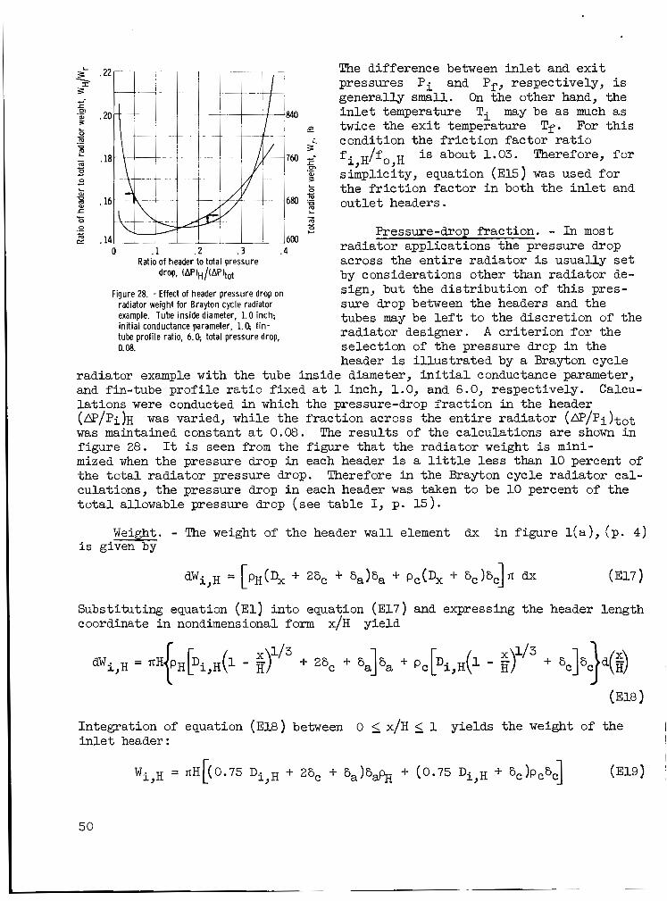
The difference between i n l e t and e x i t pressures P i and Pf, respectively, is generally small. On the other hand, the i n l e t temperature Ti may be as much as twice the e x i t temperature Tf. For t h i s condition the f r i c t i o n factor r a t i o
is about 1.03. Therefore, f o r simplicity, equation (E15) was used fo r the f r i c t i o n fac tor i n both the i n l e t and out le t headers.
i, o,H
Pressure-drop *action. - In most radiator applications the pressure drop across the en t i r e radiator is usually s e t by considerations other than radiator de- sign, but the d is t r ibu t ion of t h i s pres-
tubes may be l e f t t o the discret ion of the radiator designer. selection of the pressure drop i n the header i s i l l u s t r a t ed by a Brayton cycle
Ratio of header to total pressure drop, (AP)H/(AP)tot
Figure 28. - Effect of header pressure drop on radiator weight for Brayton cycle radiator sure drop between the headers and the example. Tube inside diameter, 1.0 inch; init ial conductance parameter, 1.0, f in - tube profile ratio, 6.0 , total pressure drop, 0.08.
A c r i t e r ion f o r the
radiator example with the tube inside diameter, i n i t i a l conductance parameter, and fin-tube prof i le r a t i o f ixed a t 1 inch, 1.0, and 6.0, respectively. la t ions were conducted i n which the pressure-drop fract ion in the header (&'/pi)H was maintained constant a t 0.08. figure 28 . mized when the pressure drop i n each header i s a l i t t l e l e s s than 10 percent of the t o t a l radiator pressure drop. Therefore in the Brayton cycle radiator cal- culations, the pressure drop i n each header was taken t o be 10 percent of the t o t a l allowable pressure drop (see table I, p. 15).
Calcu-
was varied, while the fract ion across the en t i r e radiator (&P/Pi)tot The r e su l t s of the calculations a re shown i n
It i s seen from the figure tha t the radiator weight is mini-
Weight. - The weight of the header wall element dx i n f igure l ( a ) , (p . 4) i s given by
dWi,H = [PH(Dx + 26, + 6a)6a + Pc(Dx + 6c)Sc]' dx (E17 1 Substituting equation ( E l ) in to equation (E17) and expressing the header length coordinate i n nondimens ional form x/H yield
50

The weight of the out le t header i s obtained in a similar manner, and i s given a s
The combined w e i g h t of the i n l e t and out le t headers i s
Vulnerable area. - The vulnerable area of the headers f o r the configura- t ions shown i n figures 1 and 2 was taken as the outside surface area of the headers. d i f f e ren t i a l area over the header length (f ig . l ( a ) )
The outside area of the inlet header is calculated by integrating the
o r
A similar expression is obtained fo r the outside area of the out le t header:
(A ) = nH(0.75 D o,H + 26, + 26,) o,H 0
The t o t a l outside area for both headers is then
+ D o,H ) + 4(6, + S,)]
However, the armor thickness 6, i s unknown (see appendix B) . Therefore, t o eliminate the need of another set of i terat ions, the vulnerable area of the headers was assumed, f o r simplicity, i n t h i s analysis t o be given by
The vulnerable area of the headers from equation (E26) can then be combined with the vulnerable area of the tubes f o r use i n equation (Bl).
Radiation. - The amount of radiat ion from an exposed header is a function primarily of i t s temperature and outer surface area. I n t h i s analysis it w a s assumed tha t the surface temperatures f o r the i n l e t and out le t headers were equal t o the surface temperatures of the f irst and l a s t s t r ips , respectively, in to which the tubes w e r e divided (see ANALVSIS sect ion) .
The approximate rate of heat re ject ion by thermal radiation from the i n l e t
51

Ratio of header to total pressure drop, (AP)H /(AP)tot
Figure 29. - Effect of header pressure drop on header surface area and header heat rejec- t ion for Brayton cycle radiator example.
between a header on one panel and any other header a s wel l as mutual shielding by the headers and panels were neglected. The r e su l t s of these calculations a re shown i n f igure 30, where the fract ion of heat radiated by the headers i s plot ted against the number of radiator panels f o r near-minimum-weight condi- t ions . It i s seen from the f igure that the heat re jected by the headers i s
Number of radiator panels
Figure 30. - Effect of paneling on heat rejection from headers for Brayton cycle radiator example.
and out le t gas headers w a s calculated by using the following equation:
a r e the surface temperatures of the f i rs t and the last where T o , l and To,, s t r i p s of the radiator panel, respectively (see f i g . 2 ( a ) ) . assumed tha t the radiat ion from the headers does not a f f e c t the temperatures, pressures, and other properties of the gas a t the radiator i n l e t and ou t l e t . The surface emissivity E and the equivalent sink temperature Ts were con- sidered t o be the same as f o r the radiat ion from the f i n s and tubes (see tab le I) . The fac tor FH equal t o 0.9 was included t o account f o r the radiant interchange between the headers, f i n s , and tubes. The in l e t - and outlet-header surface areas ( A
t ions (E23) and (E24), respectively.
It w a s a l so
) and ( A o , ~ ) , respectively, were obtained from equa- o,H i 0
Figure 29 i l l u s t r a t e s the var ia t ion i n the heat re jected by the headers, expressed as a f rac t ion of the panel heat-rejection r a t e , and header outer sur- face area as a function of the header pressure-drop f rac t ion . It is seen from the figure t h a t f o r a header pressure-drop f rac t ion near t h a t corresponding t o m i n i m u m radiator weight, the heat re jec t ion from the headers amounts t o between 7 and 8 percent o f the panel heat re ject ion. ,
The preceding discussion has i l l u s t r a t e d the magnitude of the percentage I
of heat radiated from the headers f o r a Brayton cycle radiator example, as well
52

as the various factors tha t contribute t o t h i s heat rejection. ea r l i e r , the heat rejected from the headers was neglected i n t h i s program for simplicity. i s substantial , an approximate procedure, presented i n a l a t e r part of t h i s appendix, can be used t o obtain an estimate o f the e f fec t of header radiation on the radiator geometry and weight.
As mentioned
If f o r cer ta in applications the thermal radiation from the headers
Liquid Headers
The design of the headers fo r the radiators that use l iquid o r l iqu id metal as a working f l u i d was simplified by assuming that the headers were tubu- lar with uniform diameters. Consideration was given t o the use of tapered l iqu id headers i n order t o reduce the header and radiator weight. shown, however, t ha t i f tapered instead of s t ra ight headers are used i n both of the foregoing examples, the minimum weight of the radiator, including the weight of the l iquid content i n the headers, i s reduced by l e s s than 2 . 5 per- cent.
It can be
It was a l so assumed tha t the working f l u i d enters the i n l e t header a t the middle and leaves the out le t header a t the same position ( f i g . l ( b ) ) . Such a design provides some saving i n header weight, since, i n such an arrangement, each half of the header handles only one-half of the t o t a l mass flow. Other arrangements, such as the U-type or Z-type headers a re discussed a t the end of t h i s section.
Pressure drop. - For equal flow distribution among the tubes, the follow- ing equation should be sa t i s f ied :
The allowable pressure-drop re la t ion is obtained by integrating equation (E2) , where the mass velocity i s now evaluated from equation (E28) and the continuity equation for constant diameter as
h ( 0 . 5 - x) HT
The f r i c t i o n factor with turbulent flow assumed i n the headers is given by equation ( ~ 2 a ) .
Substi tuting equations (E29) and ( C 2 a ) into equation ( E 2 ) makes the l a t t e r a function of one independent variable only:

5100
4900
(b) Header weight.
\ - -- 14 -
8 Ratio of header to total pressure drop, (AP)H/(AP)tot
(c) Heat-rejection rate.
Figure 31. - Variations in radiator total and header weight and header heat-rejection rate wi th header pressure drop and total allowable pressure drop for Rankine cycle radiator ex- ample. Tube inside diameter, 0.625 inch; in i t ia l conduc- tance parameter, 0.5; f in-tube profile ratio, 2.0. (See table I for other inputs. )
The integration of equation (E30) yie lds the desired re la t ions between length, diameter, and pressure drop:
When the header diameter i s taken as the dependent variable, equation (E31) becomes
54

0.208 -0.375 %,H = 0.174 m c1
Weight. - The combined weight m e t a l headers, including armor and ta ined from
r-
of the i n l e t and ou t l e t l iqu id or l i qu id m e r , but without l iqu id content, can be ob-
+ 2% + %) + Pc%(?L,H + %)] where H is determined from equation (E5), Sa from equation (Bl), 6, from equation (E), and the inside diameter of the headers, equation (E32). The material densi t ies pc and pH are inputs (see t ab le I).
i s obtained from
Pressure-drop fract ion. - An analysis similar t o that f o r the Brayton cycle rad ia tor example was made of the headers of the Rankine cycle rad ia tor and the secondary cooling rad ia tor example by calculating the e f fec ts of a change i n the pressure-drop *action i n the headers on the t o t a l rad ia tor w e i g h t and header radiat ion. sure drops across the e n t i r e rad ia tor of 4 and14 pounds per square inch. other inputs are shown i n tab le I. ductance parameters, and fin-tube p ro f i l e r a t i o s fo r t he calculations were taken f o r the near-minimum-weight condition. corresponding figures.
Calculations were made fo r t o t a l allowable pres- The
The tube inside diameters, in i t ia l con-
Tbese values are indicated i n the
Figure 31(a), f o r the Rankine cycle radiator example, shows the var ia t ion of t o t a l rad ia tor weight with the pressure drop i n each header, the Latter expressed as a r a t i o of t o t a l allowable pressure drop across the en t i r e radia- t o r . mum w e i g h t occurs when the header pressure drop is approximately 15 percent of the t o t a l allowable pressure drop. This minirmUn value i s somewhat greater than the percentage observed previously i n the Brayton cycle rad ia tor example, a l - though there is l i t t l e weight var ia t ion indicated f o r pressure-drop fract ions between 0.10 and 0.25. achieved if the allowable t o t a l pressure drop can be increased from 4 t o 14 pounds per square inch (-14 percent a t minimum-radiator-weight conditions). The main contributors t o this weight saving a r e the reduced weights of the i n l e t and ou t l e t headers a s i l l u s t r a t e d by the curves i n f igure 31(b).
For both cases investigated ( t o t a l pressure drop, 4 and 1 4 ps i ) , the mini-
It is a l so seen t h a t considerable w e i g h t saving can be
Reduction i n the header w e i g h t s as a r e su l t of the smaller header diame- ters also means smaller header surfaces and therefore smaller header heat- re jec t ion ra tes . The latter trends a re shown by the curves i n figure 31(c), which a l so indicate that a subs tan t ia l decrease i n the header heat re jec t ion results from increasing the t o t a l allowable pressure drop. the increase i n t o t a l pressure drop causes an increase of the f l u i d veloci ty a t the tube in l e t ; however, the l e v e l of the f l u i d veloci ty s t i l l remains r e l a - t i ve ly small (-16 f t / s ec ) .
On the other hand,
The same trends as i n the Rankine cycle radiator example were a l so ob- served f o r the secondary cooling radiator example ( f i g . 32 ]. the t o t a l m i n i m u m w e i g h t occurred a t a s l igh t ly lower header pressure drop
In t h i s example,
55
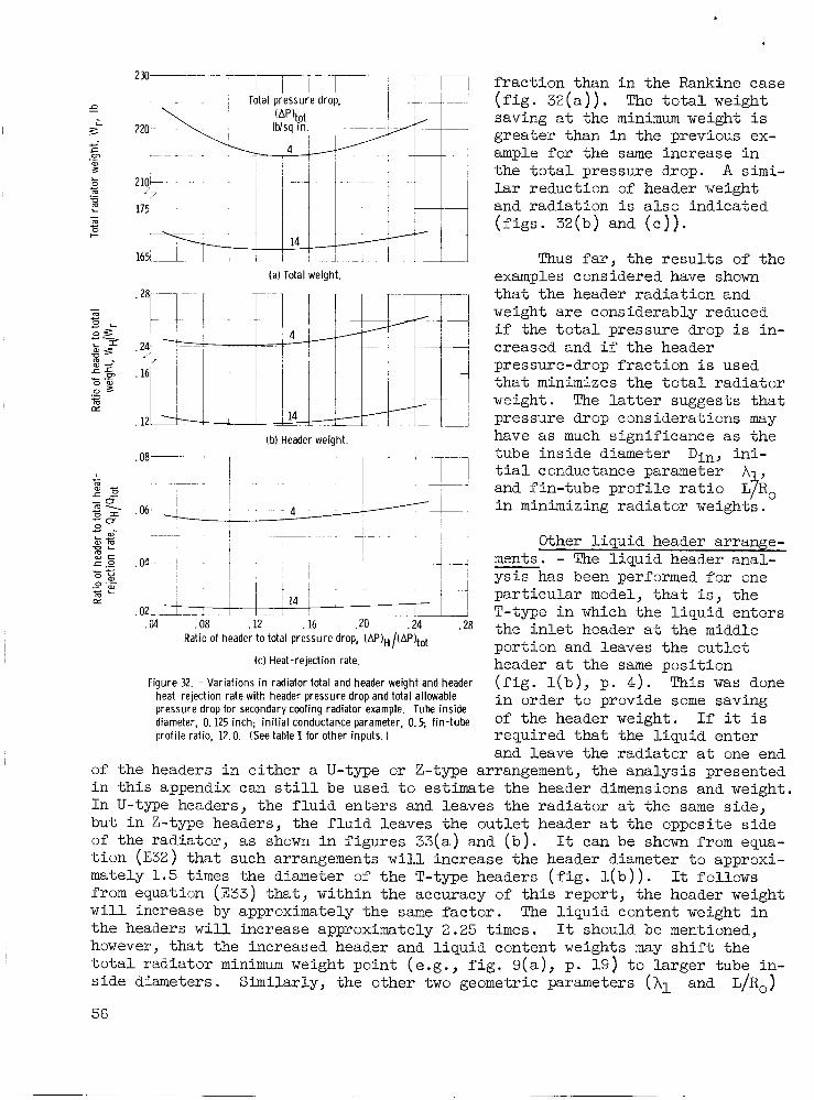
L I 3
- m c 0 c
(a) Total weight.
(b) Header weight.
1 1 I ! ! .OZ_-J--: i 1 ,
1 1 4 1 1 ,
.04 .08 . i 2 - ' .16 ,20 .24 .28 Ratio of header to total pressure drop, (AP)H/(AP)tot
(c) Heat-rejection rate.
Figure 32. - Variations in radiator total and header weight and header heat-rejection rate with header pressure drop and total allowable pressure drop for secondary cooling radiator example. Tube inside diameter, 0.125 inch; in i t ia l conductance parameter, 0.3 fin-tube profi le ratio, 12.0. (See table I for other inputs.)
f rac t ion than i n the Rankine case ( f ig . 32(a)) . The t o t a l weight saving a t the minimum weight i s greater than i n the previous ex- ample for the same increase i n the t o t a l pressure drop. A s i m i - lar reduction of header weight and radiat ion i s a l so indicated ( f ig s . 32(b) and ( e ) > .
Thus far, the r e su l t s of the examples considered have shown t h a t the header radiat ion and weight are considerably reduced i f the t o t a l pressure drop i s in- creased and i f the header pressure-drop f rac t ion i s used t h a t minimizes the t o t a l radiator weight. The l a t t e r suggests t ha t pressure drop considerations may have as much significance as the tube inside diameter D i n , i n i - t i a l conductance parameter A and fin-tube p ro f i l e r a t i o LjA0 i n minimizing radiator weights.
Other l iqu id header arrange- ments. - The l iqu id header anal- ys i s has been performed f, nr one par t icular model, t h a t is , the T-type i n which the l iqu id enters the i n l e t header a t the middle portion and leaves the out le t header a t the same posit ion ( f i g . l ( b ) , p. 4 ) . i n order t o provide some saving of the header weight. If it is required t h a t the l iqu id enter and leave the radiator a t one end
This was done
of the headers i n e i ther a U-type or Z-type arrangement, the analysis presented i n t h i s appendix can s t i l l be used t o estimate the header dimensions and weight. I n U-type headers, the f l u i d enters and leaves the rad ia tor a t the same side, but i n Z-type headers, the f l u i d leaves the out le t header a t the opposite s ide of the radiator, as shown i n f igures 33(a) and ( b ) . It can be shown from equa- t i on (E32) tha t such arrangements w i l l increase the header diameter t o approxi- mately 1.5 times the diameter of the T-type headers ( f i g . l ( b 1) . from equation ( E 3 3 ) that, within the accuracy of t h i s report , the header weight w i l l increase by approximately the same fac tor . the headers w i l l increase approximately 2.25 times. however, t ha t the increased header and l iqu id content weights may s h i f t the t o t a l radiator minimum weight point (e.g., f i g . 9(a) , p. 19) t o larger tube in- s ide diameters. Similarly, the other two geometric parameters (A1 and L/Ro)
56
It follows
The l iqu id content weight i n It should be mentioned,
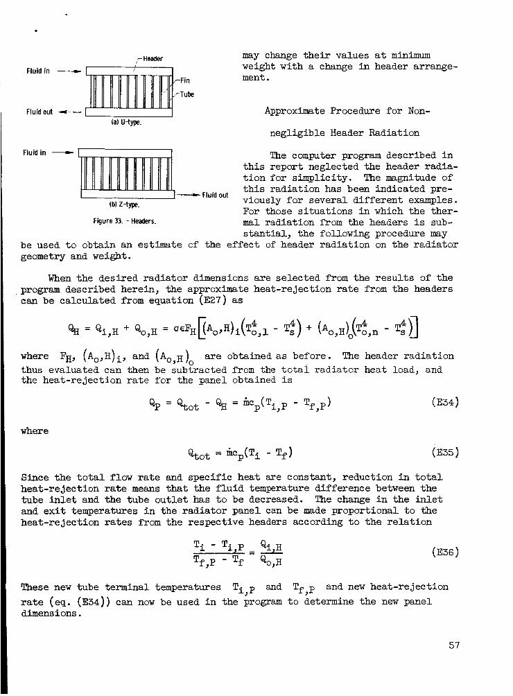
cHeader may change t h e i r values a t minimum weight with a change i n header arrange- Fluid in -
-Fin ment . -Tube
Fluid out - Approximate Procedure fo r Non-
negligible Header Radiation (a) U-type.
Fluid i n
1 I - Fluid out (b) 2-type.
The computer program described i n t h i s report neglected the header radia- t i on f o r simplicity. The magnitude of t h i s radiation has been indicated pre- viously f o r several d i f fe ren t examples. For those s i tuat ions i n which the ther-
Figure 33. - Headers. mal radiation from the headers is sub- s tan t ia l , the following procedure may
be used t o obtain an estimate of the e f f ec t of header radiat ion on the radiator geometry and w e i g h t .
When the desired rad ia tor dimensions a re selected from the r e s u l t s of the program described herein, the approximate heat-rejection rate from the headers can be calculated from equation (E27) as
where FH, (Ao,H)i, and (Ao,,,, are obtained as before. The header radiat ion thus evaluated can then be subtracted from the t o t a i radiator heat load, and the heat-rejection rate fo r the panel obtained is
where
Since the t o t a l flow r a t e and specif ic heat are constant, reduction in t o t a l heat-rejection rate means that the f l u i d temperature difference between the tube i n l e t and the tube ou t l e t has t o be decreased. The change i n the i n l e t and e x i t temperatures i n the radiator panel can be made proportional t o the heat-rejection rates from the respective headers according t o the r e l a t ion
T i - T i p Qi H Tf,P Tf &o,H
3 = A
These new tube terminal temperatures Ti,p and Tf,p and new heat-rejection rate (eq. (E34)) can now be used i n the program t o determine the new panel dimens ions.
57
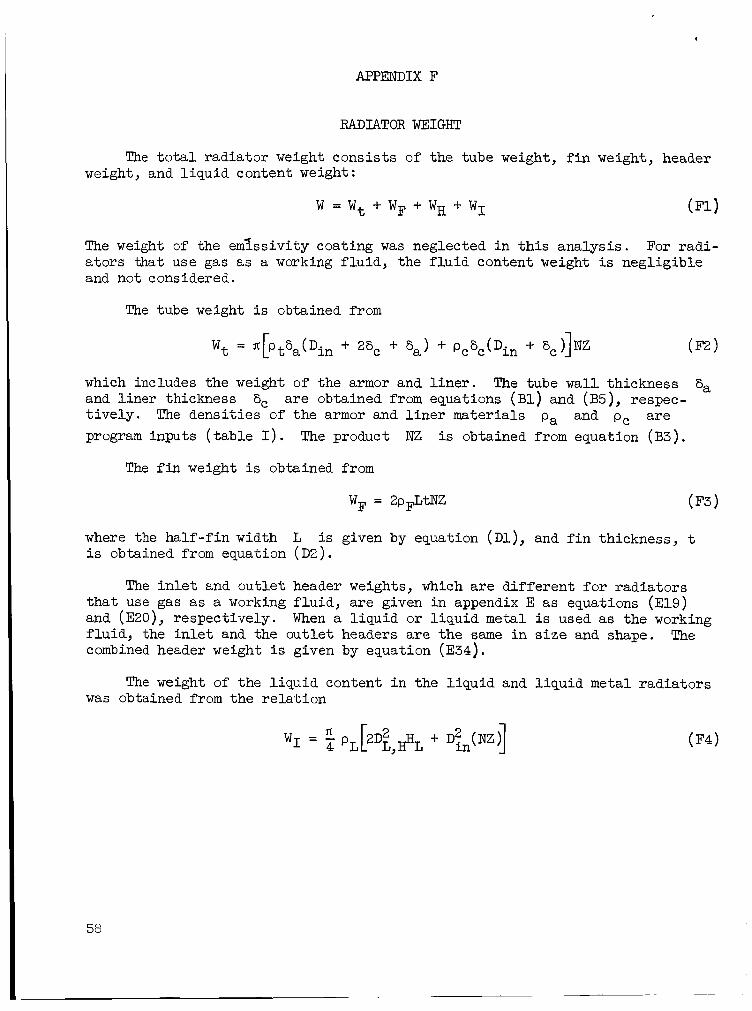
. APPENDIX F
RADIATOR WEIGHT
The t o t a l radiator weight consists of the tube weight, f i n weight, header weight, and l iqu id content weight:
The weight o f the em&,sivity coating was neglected i n t h i s analysis. a tors that use gas as a working f lu id , the f lu id content weight is negligible and not considered.
For radi-
which includes the weight of the armor and l i n e r . and l i n e r thickness a re obtained from equations ( B l ) and (B5), respec- t ive ly . The densit ies of the armor and l i n e r materials pa and pc a r e program inputs ( t ab le I) . The product NZ is obtained from equation (B3) .
The tube wall thickness 8, 6,
The f i n weight i s obtained from
where the half-f in width L i s obtained from equation ( D Z ) .
is given by equation ( D l ) , and f i n thickness, t
The i n l e t and out le t header weights, which a re d i f fe ren t f o r radiators t ha t use gas a s a working f lu id , a re given i n appendix E as equations (E19) and (EZO), respectively. f lu id , the i n l e t and the out le t headers a re the same i n s i ze and shape. combined header weight is given by equation (E34) .
When a l iquid or l iqu id metal i s used as the working The
The weight of the l iqu id content i n the l iquid and l iquid metal radiators was obtained from the re la t ion
58
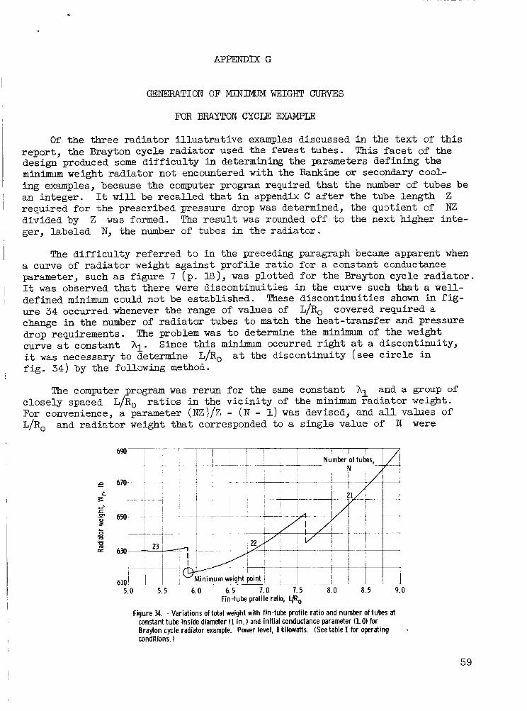
APPENDIX G
I GENEXUlTION O F MINIMUM WEIGHT CURVES
FOR BRAYTON CYCLF: ExAMpI;E
O f the three radiator i l l u s t r a t ive examples discussed i n the t ex t of t h i s report , the Brayton cycle radiator used the fewest tubes. design produced some d i f f i cu l ty i n determining the parameters defining the m i n i m u m weight radiator not encountered with the Rankine or secondary cool- ing examples, because the computer program required tha t the number of tubes be an integer. It w i l l be recal led tha t i n appendix C a f t e r the tube length required fo r the prescribed pressure drop was determined, the quotient of divided by Z w a s formed. The r e su l t was rounded off t o the next higher inte- ger, labeled N, the number of tubes i n the radiator.
This facet of the
1 ' 1
Z NZ
I The d i f f i cu l ty referred t o i n the preceding paragraph became apparent when a curve of radiator weight against prof i le r a t i o for a constant conductance parameter, such a s figure 7 (p . l8), w a s plotted for the Brayton cycle radiator . It was observed that there were discontinuities i n the curve such t h a t a w e l l - defined m i n i m could not be established. These discontinuities shown in f ig- ure 34 occurred whenever the range of values of change in the number of radiator tubes t o match the heat-transfer and pressure drop requirements. curve a t constant hl. it was necessary t o determine f ig . 34) by the following method.
1 I
L/Ro covered required a
The problem was t o determine the minimum of the w e i g h t Since t h i s minimum occurred right a t a discontinuity,
L/Ro a t the discontinuity (see c i r c l e i n
The computer program was rerun f o r the same constant A1 and a group of closely spaced L/Ro r a t io s i n the v i c in i ty of the m i n i m u m radiator w e i g h t . For convenience, a parameter (NZ)/Z - (N - 1) w a s devised, and a l l values of , L/Ro and radiator weight that corresponded t o a single value of N were
69I) i c ! __ -
I
I ,-'+ --'-
I 1
~ 21- I
630
5.0 5.5 6.0 6.5 7.0 7.5 a. o a. 5 9.0 Fin-tube profile ratio, 9,
Figure 34. - Variations of total weight with fin-tube profile ratio and number of tubes at constant tube inside diameter (1 in. ) and initial conductance parameter (1.0) for Brayton cycle radiator example. Power level, 8 kilowatts. (See table I for operating conditions. 1
.
59

6.4 1 Initial conductance
(a) Fin-tube profile ratio.
(b) Radiator weight.
Figure 35. - Variations of total weight and fin- tube profile ratio with parameter (NZVZ - (N - 1) at constant tube inside diarn- eter (1 in. ) for Brayton cycle radiator ex- ample. Power level, 8 kilowatts. (See table I for operating conditions. 1
plotted against t h i s parameter f o r each value of ure 35. when the parameter took on a value of 1, and because the range of the parameter w a s limited t o values between 0 and 1 for each value of N. The ordinate values corresponding t o an abscissa value of 1 then defined the m i n i m u m radiator weight and L/Ro required f o r minimum weight a t each value of h l . The minimum weight curve f o r each tube diameter could then be drawn by plot t ing the minimum weights against the corresponding L/Ro r a t i o s thus determined f o r each A1.
A1, as i l l u s t r a t e d i n f i g - This parameter w a s chosen because the discontinuity w a s defined
60

1. Lieblein, Seymour: Special Requirements on Power Generation Systems f o r Elec t r ic Propulsion. Elec t r ic Propulsion for Spacecraft. NASA SP-22, 1962.
2. Walker, C . L.; Smith, C . R.; and Gritton, D. G . : Weight Optimization of Heat Rejection Systems fo r Space Applications. Proc. 1960 Heat Transfer and Fluid Mech. Inst., Stanford Univ. Press, 1960, pp. 244-259.
3. Kkebs, Richard P.; Winch, David M.; and Lieblein, Seymour: Analysis of a Megawatt Level Direct Condenser-Radiator. Flight. Vol. 11 of Prog. i n Astronautics and Aeronautics, Academic Press, Inc., 1963, pp. 475-504.
Power Systems f o r Space
4. Haller, Henry C . : Analysis of a Double Fin-Tube F la t Condenser-Radiator and Comparison w i t h a Central Fin-Tube Radiator. NASA TN D-2558, 1964.
5. I(i.ebs, Richard P.; Haller, Henry C.; and Auer, Bruce M.: Analysis and Design Procedures f o r a Flat , Direct-Condensing, Central Finned-Tube Radiator. NASA TN D-2474, 1964.
6. Cooke, D. H.; Mayer, M. S.; and Thompson, C . A. : Space Power Plant Study. Frog. Rept. 2, WAMG-PR(B)-007, Westinghouse Elec t r ic Corp., Feb. 20, 1963.
7. Denington, R. J., e t al.: Space Radiator Study. Rept. No. ER-4544, Thompson Ram0 Wooldridge, Inc., 1962.
8. Schreiber, L. H.; Mitchell, R. P.; Gillespie, G. D.; and Olcott, T. M.: Techniques for Optimization of a Finned-Tube Radiator. ASME, 1961.
Paper 61-SA-44,
9. Stone R.; and Coombs, M. G.: Targe Space Radiators. Paper Presented a t U S Prop. Meeting, Cleveland (Ohio), Max. 7-8, 1963.
10. Lubin, Barry T.; and Trusch, Raymond B.: Prediction of Space Radiator Performance. Paper 63-AHGT-85, ASME, 1963.
ll. Mackay, D. B.; and Bacha, C. P.: Space Radiator Analysis and Design. TR 61-30, p t . 1, Aeronautical Systems Div., Apr. 1, 1961.
12. Rubin, Irving; and Imber, Murray: Optimization Study of Space Radiators. AIAA J., vol . 2, no. 2, Feb. 1964, pp. 353-358.
13. Anderson, R. C.; and Henderson, B. J.: A Parametric Survey of Tube and Fin Type Radiators. Rept. No. LAMS-2793, Los Alamos Sci. Lab., Oct. 1962.
14. French, Raymond, J., Jr.: Analysis and Experimental Verification of Space Radiator Performance. Paper No. 845B, SAE-ASME, 1964.
61

15. Glassman, A. J.; Krebs, R . P.; and Fox, T . A . : Brayton Cycle Nuclear Space Power Systems and Their Heat Transfer Components. A.I.Ch.E., 1963.
Paper No. 57,
16. Lieblein, Seymour: Analysis of Temperature Distribution and Radiant Heat NASA TN D-196, Transfer Along a Rectangular Fin of Constant Thickness.
1959.
1 7 . Loeffler, I. J.; Lieblein, Seymour; and Clough, Nestor: Meteoroid Protec- t ion f o r Space Radiators. Prog. i n Astronautics and Aeronautics, Academic Press, Inc., 1963,
Power Systems for Space F l ight . ' V o l . 11 of
pp. 551-579.
18. Sparrow, E. M.; Jonsson, V. K.; and Minkowycz, W . J.: Heat Transfer from Fin-Tube Radiators Including Longitudinal Heat Conduction and Radiant Interchange Between Longitudinally Nonisothermal F in i te Surfaces. NASA TN D-2077, 1963.
1 9 . Knudsen, James G.; and Katz, Donald L . : Fluid Dynamics and Heat Transfer. McGraw-Hill Book Co., Inc . , 1958.
20. Eckert, E . R . G . ; and Drake, Robert M. , Jr.: Heat and Mass Transfer. Second ed., McGraw-Hill Book Co., Inc . , 1959.
21. Sparrow, E . M.; and Eckert, E . R . G . : Radiant Interaction Between Fin and Base Surfaces. Feb. 1962, pp. 12-18.
J. Heat Transfer (ASME Trans.), ser. C, vo l . 84, no. 1,
22. Auer, Bruce M; and Saule, Arthur V . : Program Details f o r Design of Sensi- ble Heat Space Radiators, NASA TN D-2840, 1965.
23. Weatherford, W . D. , Jr.; Tyler, John C . ; and Ku, P . M . : Properties of Inorganic Energy-Conversion and Heat-Transfer Fluids fo r Space Applica- t ions. TR 61-96, WADD, Nov. 1961.
24. Hatton, Roger E . : Introduction t o Hydraulic Fluids. Reinhold Pub. Corp., 1962.
25. Svehla, Roger A . : Estimated Viscosit ies and Thermal Conductivities of Gases a t High Temperatures. NASA TR R-132, 1962.
62 NASA-Langley, 1965 E-2769