analysis visco i1 - nasa
TRANSCRIPT

The University of Tennessee
Department of Mechanical and Aerospace Engineering
ANALYSIS OF THE VISCO SEAL
PART I1
THE CONCENTRIC TURBULENT CASE
by
William K . Stair
Robert H . Hale
Investigation conducted for the National Aeronautics and Space Administration
under Research Grant NsG- 587
Reproduction in whoit: er in part is permitted for any purpose of the U . S . Government
June 28 , 1966
Knoxville, Tennessee
ME 66-587-7

- : This
analysis of the
approach taken
turbulent flow.
w-
ABSTRACT .--*
report, the seventh of a series >: presents a theoretical
visco seal when operating in turbulent flow. The general
was to modify the Navier-Stokes equations for use in
1- L
Using a n approach similar to that of S . I. Pai , the velocity
profile in the seal was represented a s a power series and a solution of the
resulting fiow eqaatiens resulted in a n equation for the sealing coefficient
suitable for laminar or turbulent flow.
An approximate method has been devised wherein the friction
data for ordinary pipe flow can be utilized to determine the experimental
factors in the sealing equation. From the experimental study of ten seal
geometries it was observed that the agreement between theory and experi-
ment was quite satisfactory for purpo$es of seal design.
ii

TABLE OF CONTENTS
CHAPTER PAGE
I . INTRODUCTION AND ANALYTICAL HISTORY OF THE VISCO SEAL . 1
Introduction . . . . . . . . . . . . . . . . . . . . . . . 1
Historical Presentation of Laminar Visco Seal Analyses 1
9
I1 . DEVELOPMENT OF THE SEALING COEFFICIENT . . . . . . . . . 11
Basic Flow Equations . . . . . . . . . . . . . . . . . . . 11
Basic Flow Equations Applied to the Conditions of the
. . . . Comparison of Laminar Analyses for the Visco Seal . . . . . .
ViscoPump . . . . . . . . . . . . . . . . . . . . . . 14
Generalizing the Theoretical Sealing Coefficient for
Laminar and Turbulent Operation . . . . . . . . . . . . . 33 I11 . TEST FACILITY AND EXPERIMENT PROCEDURE . . . . . . . . . 39
Test Facilities . . . . . . . . . . . . . . . . . . . . . . 39
Test Procedure . . . . . . . . . . . . . . . . . . . . . . 39
IV . EXPERIMENTAL RESULTS . . . . . . . . . . . . . . . . . . . 46 Sealing Coefficient . . . . . . . . . . . . . . . . . . . . 46
Friction Parameter and Dissipation Function . . . . . . . . . 58
Air Ingestion . . . . . . . . . . . . . . . . . . . . . . . 63
Long Term Seal Operation . . . . . . . . . . . . . . . . . 64 Other Experimental Results . . . . . . . . . . . . . . . . . 66
V . CONCLUSIONS AND RECOMMENDATIONS . . . . . . . . . . . 68 LIST OF REFERENCES . . . . . . . . . . . . . . . . . . . . . . . 71
APPElGXCEE
A . SAMPLE CALCULATIONS . . . . . . . . . . . . . . . . . . 75 B . COMPUTER PROGRAM FOR THE SEALING COEFFICIENT . . . . . 79
iii

LIST OF TABLES
TABLE
I. Dimensionless Parameters. . . . . . . . . . . . . . . . . 11. Dimensionless Simplifying Terms. . . . . . . . . . . . . .
111. Geometric Parameters for Test Spindles . . . . . . . . . . . IV. Comparison of Test Seal Geometries . . . . . . . . . . . . V. Comparison of Test Resul t s . . . . . . . . . . . . . . . .
PAGE
17
28
43
47
49
iv

FIGURE
1.
2 .
3.
4.
5.
6.
7.
8.
9.
10.
11.
12 .
13.
14.
15.
16.
17.
18.
19.
LIST OF FIGURES
PAGE
2 . . . . . . . . . . . . . . Basic Elements of the Visco Seal
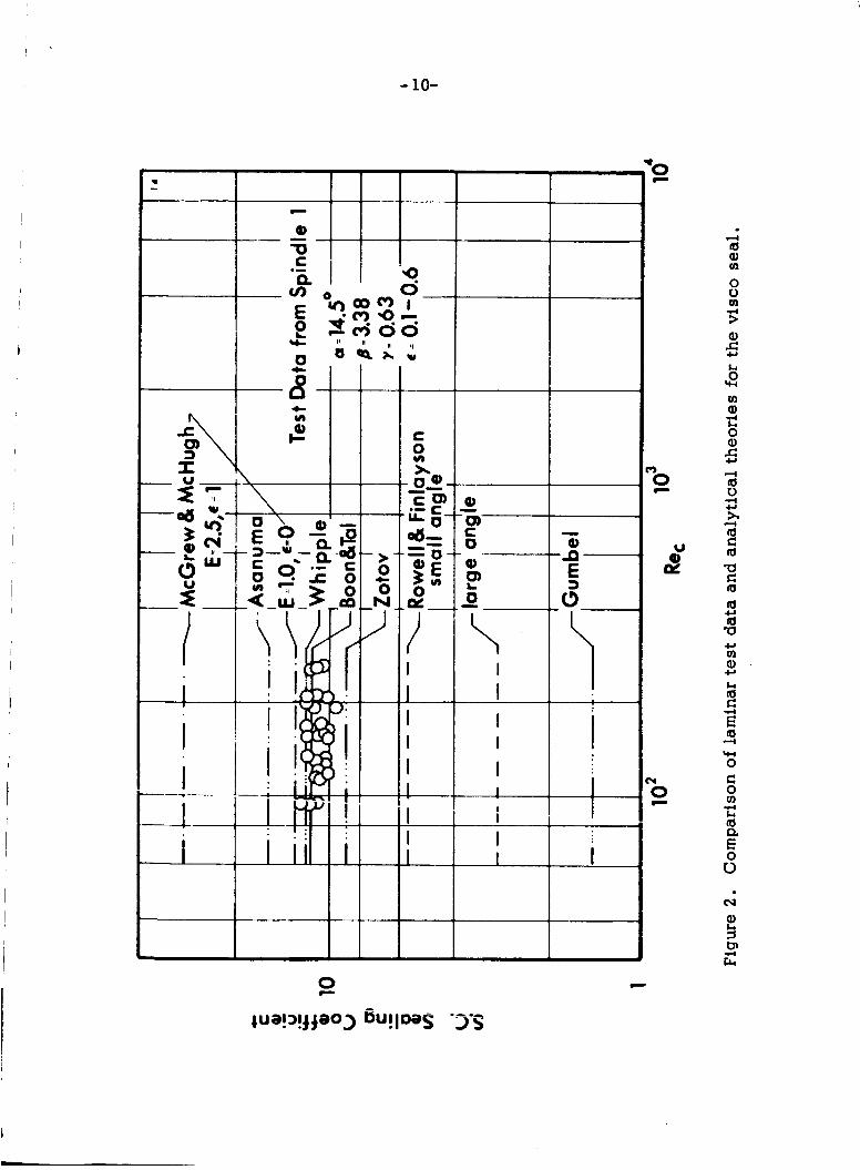
Comparison of Laminar T e s t Data and Analytical Theories for
the Visco Seal . . . . . . . . . . . . . . . . . . . . . 10
Developed View of the Visco Seal Geometry . . . . . . . . . 12
Model for Groove and Land Flow . . . . . . . . . . . . . . 15
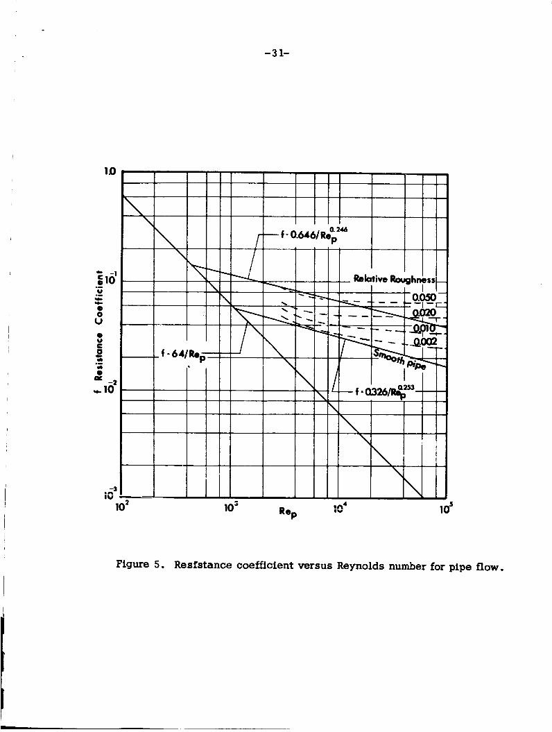
Resistance Coefficient Versus Reynolds Number for Pipe Flow . . 31
Theoretical
7 fora =
Theoretical
7 fora =
Theoretical
7 for a =
Theoretical
7 f o r a =
Sealing Coefficient as a Function of f3 , Re,, and
5.81", c = 0.003 in . , and D = 1.25 in. . . . . . . . 34
Sealing Coefficient as a Function of f3 , Re,, and
9.67", c = 0.003 in . , and D = 1.25 in. . . . . . . 35
Sealing Coefficient as a Function of f3, Re,, and
14.5", c = 0.003 in . , and D = 1.25 in. . . . . . . 36
Sealing Coefficient as a Function of B , Re,, and
20. 15O, c = 0.003 in . , and D = 1.25 in. . . . . . . 37
Visco Seal Test Facilities. . . . . . . . . . . . . . . . . . 40
Schematic Diagram of the Visco Seal Test Section . . . . . . . 41
Typical Pressure and Temperature Gradients in the Visco Seal . . 42
Visco Seal T e s t Spindles . . . . . . . . . . . . . . . . . . 44
Theoretical and Experimental Sealing Coefficient for Spindle 1 . . Theoretical and Experimental Sealing Coefficient for Spindles
48
2 , 3 , and 4. . . . . . . . . . . . . . . . . . . . . . . 51
Theoretical and Experimental Sealing Coefficient for Spindles
. . . . . . . . . . . . . . . . . . 52 n- -n - - A A D &D, 3D, U A A U IY - - -
Theoretical and Experimental Sealing Coefficient for Spindles
5, 6 , a n d 7 . . . . . . . . . . . . . . . . . . . . . . . 53
and 20.15O with 7 of 0.3 and 0 .7 . . . . . . . . . . . . . Theoretical Sealing Coefficient Versus Rec for a of 5.8 lo
54
Theoretical and Experimental Sealing Coefficient for Spindles
2 and 2 B . . . . . . . . . . . . . . . . . . . . . . . . . 55
V

FIGURE
20.
21.
22 .
23.
24.
25.
26.
27.
Theoretical and Experimental Sealing Coefficient for Spindles
3 and 3B . . . . . . . . . . . . . . . . . . . . . . . Theoretical and Experimental Sealing Coefficient for Spindles
4 and 4B . . . . . . . . . . . . . . . . . . . . . . . Theoretical Sealing Coefficient for Spindles SA, 6A, and 7A. . Theoreticai and Experimental Friction Parameter for Spindles 1,
2 , 3 , a n d 4 . . . . . . . . . . . . . . . . . . . . . . Theoretical and Experimental Friction Parameter for Spindles
PAGE
2B, 3B, and4B . . . . . . . . . . . . . . . . . . . . . Theoretical and Experimental Friction Parameter for Spindles
5, 6 , a n d 7 . . . . . . . . . . . . . . . . . . . . . . . Schematic Representation of the Change in B Due to Air
I n g e s t i o n . . . . . . . . . . . . . . . . . . . . . . . . Comparison of King's Experimental Data with the Theoretical
Sealing Coefficient . . . . . . . . . . . . . . . . . . . .
56
57
59
6G
61
62
65
67

A
a
b
C l lC2
c5'c20 C
D
f
h
h g = h + c
j = b cos a j ' = a cos a L
1
M
M '
N
N '
n
n
P
P -
P' - P1
Q
NOMENCLATURE
Area, in.
Axial land width, in.
Axial groove width, in .
Terms in equation 11
Experimental coefficients in equation 17
Constants of integration
Radial clearance , in,
Seal diameter, in.
Eccentricity factor i n equation 14
Friction parameter
Resistance coefficient , Figure 5
Groove depth, in .
Film thickness over grooves , in.
Groove width , in.
Land width , in.
Active seal length , in.
Axial threaded length of sea l , in.
Exponent in equation 70
Exponent in equation 7 1
Exponent in equation 58
Exponent in equation 59
XUi i ik i cf thread starts
Exponent in equation 17
Instantaneous pressure , lbf ./in. Time averaged pressure , lbf ./in. 2
Turbulent fluctuating pressure, lbf ./in.
Pressure at [* = 0 , q*= 0 , and z* = - Sealant flow rate , in. 3/sec.
Power loss , iii. W./SPC
vii
1, lbf./in. 2

U C P = -ii-
S.C. ( )
S
S*
T
t = tan a
U
u' , v' ,w'
X
Y Z
h + c p = - C
b 7 =a+b
E
rl A P 5 P
;
Reynolds number based on clearance
Theoretical sealing coefficient as presented in Chapter
Thread pitch, in .
Thread pitch per thread, in .
Time, sec.
Tangent of the helix angle
Surface velocity of the sea l , in ./sec.
Instantaneous velocity component in the
Time averaged velocity component in the
Turbulent fluctuating velocity component in the
x coordinate in the direction of motion
y coordinate along shaft axix
z coordinate in the radial direction
I. Letter in brackets refers to author.
5 , T . , t , 7 1 '
5 ,
and z directions , in ./sec .
and z directions , in ./sec.
7 , and z directions, in./sec.
Helix angle, degrees
Dimensionless parameter
Dimensionless parameter
Half thickness between parallel plates , in.
Eccentricity ratio
7 coordinate
Sealing coeiiir;iailt 2 s ?resented in this work Absolute viscosity, lbf. sec ./in. 2
( coordinate
Density, lbf. sec . 2/in. * Wall shearing s t ress , lbf ./in.
Dissipation function
viii

Subscripts
c;
ct
4 E
0
P
P r
T
‘I s Superscript *
Denoting evaluation on clearance
Denoting Couette flow
Denoting centerline
Denoting experimental
Denoting grooves
Denoting f i lm thickness
Denoting film thickness over grooves
Denoting laminar flow
Denoting turbulent flow
Denoting Poiseuille flow
Denoting pipe Reynolds number
Denoting lands
Denoting theoretical
Denoting 77 direction
Denoting 5 direction
Denoting non- dimensional term
ix

I ' CHAPTER I
INTRODUCTION AND ANALYTICAL HISTORY OF THE VISCO SEAL
I. INTRODUCTION
The visco seal, which has been referred to in literature as screw
seal, spiral groove seal, threaded seal, viscosity pump, and viscosity
seal, is a rotating device which wil l develop a pressure gradient in the
fluid annuhis around a shaft by means of helical grooves located either
on the shaft or in the housing, The basic elements of a visco seal are
shown in Figure 1. Since there is normally no contact between the rotating
shaft and the housing, the visco seal has been considered for use in critical
apparatus which require long life, such as liquid metals systems in space \
power plants and pumps and compressors in nuclear power reactor systems
as well as in various pumps, compressors, and turbines in more conven-
tional systems. The increased interest in visco sea l application in both
the aerospace and basic industries was the impetus for this work.
Analytical work on the visco seal has been limited primarily to
the laminar flow case. The means of predicting the operation of the visco
seal in the turbulent region has been, in the main, empirical. The object
of this study is to develop a theory for predicting the performance of the
visco seal when operating in the turbulent range, and to determine the
correlation between the theory developed and experimental evidence
obtained for a number of seal geometries.
XI. HISTORICAL PRESENTATION OF LAMINAR VISCO SEAL ANALYSES
The first notable laminar analysis of the visco seal was presented
by Rowell ana Piniaysorl r l l L A J
equations for two-dimensional incompressible flow and assuming the clearance
between the screw and housing to be zero, Rowell and Finlayson developed
an equation for the discharge from a visco pump which neglected the effects
L~~ * - - Q+=tinc _-_____ with the Navier-Stokes
l X u z - h s s t_n_ brackets refer to similarly numbered references listed at the end of this report.

- 2-
I
I
I- c)

- 3-
of the screw helix angle, a . This equation is:
inh 1
Q = 2 j 2 [* i=l i3 (cosh- + 1)
Equation (1) was believed to be suitable for visco pumps having a small
helix angle. When the helix angle was large enough to be significant
Rowell and Finlay son recommended that the discharge be evaluated as:
8U cos CY x3 r i= 1
inh tanh 2' 13
While Rowell and Finlayson were considering the device as a pump which
could obtain a theoretical maximum efficiency of 3 3 . 3 3 per cent they
envisioned the visco pump being operated at shut off head or no-flow
condition, thus becoming a visco seal. Setting the discharge equal to
zero ana dt:fiiiinS 2 sealing coefficient equation 2 becomes:
i= 1 i5

- 4-
It is noted that the sealing coefficient i n equation 3 depends upon the groove
depth, groove width, and helix angle, but does not distinguish between
laminar and turbulent operation. Thus, the sealing pressure developed would
be a linear function of the shaft speed. Rowel1 and Finlayson considered the
geometry of the grooves in regard to their effect on the pump performance but
did not attempt to establish an optimum seal geometry.
Whippie 121 devehped B theory for the pressure distribution and
load capacity for a herringbone type thrust bearing. His equations can be
transformed to apply to the present seal geometry. The equation for the
sealing coefficient based on Whipple's work becomes:
- 6 P U L - - (w.) A P c 2 S.C.
Whipple determined the optimum geometry, giving a minimum value of the
sealing coefficient a s 10.96, resulting when B = 3.61, T= 0.5, and a =
13.75". Hughes [3] utilized the results of Whipple's equation in con-
structing a visco sea l and experimentally showed that the sealing pressure
c a m e within 12 per cent of the theoretical value predicted by equation (4).
Zotov [4] assumed the flow to consist of three components:
the annulus flow parallel to t h e shaf t axis due to the pressure gradient,
the flow along the grooves caused by the pressure gradient, and the flow
along the grooves due to the rotation of ine shaft. The three flow
components were identified as: land pressure flow,
4nDA Pc2 (a + b) ru= Q r = m I
groove pressure flow
(5)

2 fiD a P jh tan a s in a 12 PL (a + b) Qg = k I
and groove rotational flow,
nD U hj s i n a
where the factors m and k are given by:
-0.75 m = 5.31 x
and
(3 k = 1 - 0.63
when 0 cd < 0.8. Combining equations (5) , (6), and (7) to form the total
flow, and setting th i s quantity equal to zero, which represents the condition
of sealing, the sealing coefficient becomes:
C
Equation (8) is a function of groove width, land width, helix angle, groove
depth, imd c!earsr?ce. E-quation (8) does not, however, take into account
turbulence. As the rotational speed increases, Zotov's theoretical seal-
ing coefficient, l ike Rowel1 and Finlayson's and Whipple's,will remain
constant. Optimizing Zotov' s equation produces a sealing coefficient of
8.69 for a screw geometry of T= 0.63, 01 = 1 4 . 5 O , and B = 4.12.
One of the earliest reports in which experimental data are re-
corded either for a visco pump or a visco sea l operating in the turbulent
region was presented by Frossef [5] . Limited a r ~ l y t i c a l work is

- 6-
incorporated in this paper which is primarily devoted to reporting experi-
mental data for the various screw threads tested. Frossel uses an equation
developed by Gumbel to describe the discharge from the visco pump as:
n j h (Ucosa - - h2 ") 6cc d l
Q =
In developing equation (9), Gumbel assumed one dimensional flow along
the grooves only. Thus equation (91, writtenf in te rms of the s e a l i ~ g coef-
ficient, becomes:
- 6 UL - - I-(= h2 t ana (G.) a P S.C.
Frossel concludes that for a visco pump the trapexoidal thread shapes
are the mos t practical, since they have the largest flow cross-section
with the lowest fricitional loss. Frossel notes in his discussion that a s
the shaft speed was increased, discontinuities occurred in the data
which were attributed to turbulence. Frossel made no attempt, however,
to predict the point where turbulence occurs or how the visco pump should
behave during turbulent operation.
Asanuma [ I 6 analyzed the performance of the visco pump by
considering the pump delivery to be composed of two parts: actual
delivery and flow leakage. Asanuma's equation for the sealing coefficient
was:
where
c1 = (y) - 7 8B2 (:E{% sin? [cos- isc - (-l)i] tanh N l W
8 1 i= 1
in 28 (3 I

I . -
L Setting equation (14) equal to zero, McGrew and McHugh's sealing coef-
ficient becomes:
and
- 7-
L
c 2 = ( B - 112 (B + 2) + -+ P1-(y) ] B3 B
In equation (1 1) the sealing coefficient is a function of groove width and
depth, clearance , land width , and helix angle , but is independent of
rotational speed. Asanuma suggests that the best sealing coefficients
will be obtained for r= 0 . 5 , a = 10" to 1l0 and B = 6.0.
I
I
McGrew and McHugh [ 71 reported experimental data obtained
from tests in both laminar and turbulent operation and presented an ana-
lytical solution for the sealing performance under laminar conditions.
McGrew and McHugh , following the work of Zotov, assumed that the total
flow in the pump is comprised of three main components: a flow due to
shear, a minus pressure flow in the grooves , and a negative leakage flow.
The equation for the total flow in the pump becomes:
3 nh (s* - a) cos a sin a A. P 2 - n h U (s* - a) cos a
12p L Q = 2 ( l + f )
EZ B S C 3 A P 1 2 1 n a L
3 nh (s* - a) cos a sin a A. P 2 - n h U (s* - a) cos a
12p L Q = 2 ( l + f )

1 - 8-
where 2 E = 1 + 1.56
The theoretical s e a h g coefficient in equation (1 5) is a function of clearance,
groove depth, groove and land widths I helix angle, and eccentricity ratio
but is independent of speed . Minimizing the sealing coefficient, equation
(15) produces a sealing coefficient of 9.83 for 7 = 0.5, 01 = 21,6O, and
B = 3.78. For the turbulent analysis of the visco seal McGrew and McHugh
employed a Prandtl mixing length type of solution, and expressed the axial
pressure
equation
describe
gradient in t e r m s of three experimentally determined factors. The
which best fits McGrew and MeHugh's data, and the one used to
operation in the turbulent region is:
The empirical factors in equation (16) were obtained from the data
for a single screw geometry and affords no provision for a change in seal
geometry.
turbulent flow was published by King [8] who used the equation,
A recent source of data for the operation of the visco seal
- 1 -
U L S;C. , , \ - - - L= 3 3 [ C3 + C4 R e l g ] I
c- n P m e /
in
(17)
develQped by McGrew and McHugh. King fits equation (17) to his experi-
mental data and can therefore determine the experimental constants.
operation of the visco seal was presented by Boon and T a l [g] . Stair [lo] , whose laminar analysis of the seal parallels Boon and Tal's, both refines and
expsnds the equations developed by Boon, arriving at a sealing coefficient
Of:
The analytical solution which appears to best describe the laminar

- 9-
2 - 1 ) . 3 - - & - B3 (1 + t2) + t2 7 (1 - 7) (p
- 2 S.C. C A P
Equation (18) is dependent on land and groove width, groove depth, clear-
ance, and helix angle. Optimizing equation (18) results in a sealing
coefficient of 10.97 for a seal having r= 0.5, B = 3 .65 , a n d a = 15.68O.
III. COMPMUSOPU' OF LAMINAR -LQALYSES FOR THE VISCO SEAL
A comparison of the laminar analyses for the visco seal is pre-
sented in Figure 2. All theories are compared using the s a m e geometrical
screw configuration of 7 = 0 . 6 3 , B = 3 . 3 8 , and a = 14. So . The sealing
coefficients in Figure 2 were computed as
6 b ! U L
C A P 2 I
which required modification of some equations in order to gain a common
ground for comparison. Rowel1 and Finlayson's and Gumbel's equations , both of which were derived neglecting the leakage flow across the lands,
appear to be considerably in error, while the predictions of McGrew and
McHugh (E = 0) , Zotov, Whipple, Asanuma, and Boon and Ta l compare more
favorably with the experimental values.
The approach taken in this work will be to extend Boon and Ta l ' s
laminar analysis for the sealing coefficient of the visco sea l to both laminar
and turbulent operation.
I
- 10-
'0 c
I
3 0 c
i? w
k 0 c
4 4 a, m 0 u m -4 > a, 5 8 yc
m a, L 0 a,
4
s 4 4 u h
4 a c 4 4 4 a m a,
4 c
4
0 c 0 m
-4 c,
4 z
c,
c,
c, L
3 4
+I
4
9 E" 0 u cv
2
;z 7 e

-11-
CHAPTER I1
DEVELOPMENT OF THE SEALING COEFFICIENT
I . BASIC FLOW EQUATIONS
In analyzing the flow in the visco seal it will be assumed that
the f i lm thickness is s m a l l as compared to the radius. Hence, neglecting
the curvature of the seal the problem reduces to the one shown in Figure 3 .
It is noted, however, that for smai i diameter shafts and high rotational
speeds this assumption becomes less valid due to the centrifugal acceler-
ation of the fluid. The basic describing equations will be written in the
( , 7 coordinates. The two sets of coordinate axes are related by:
= cos a + y s in a
, and z coordinates and later transposed to the x, y , and z
(19)
(2 0)
and
71 = y c o s a - x s i n c r . The Navier-Stokes equations for a Newtonian fluid, neglecting
body forces and assuming that the flow is incompressible, steady, and
laminar, are:
and
The law of continuity requires that:
To apply equations (2 1) through (24) to turbulent flow , the instan-
taneous velocity component may be considered to contain two parts: the
mean velocity component and the turbulent fluctuating component. This
esncept can also be applied to the pressure. Therefore:

- 12-

- 13- -
u = u + u ' t
V'V+V'#
w = w . + w ' ,
- -
and - P=P+P'.
"sing equations (2 5) through (28) in equations (2 1) through (24j and t i m e
averaging and combining equations (2 1) through (24) the Reynolds equations I
as reported by Pai [ll] I are formed. Hence:
and
In equations (29) through (31) I all three turbulent fluctuating
velocity components are assumed to be of the same order of magnitude.
Noting that Az is sma l l as compared to A[ and A?
negligible with negligible pressure change in the z direction, the Reynolds
equations become:
- and assuming w is

- 14- I . I - I 1
I
and
(3 3)
Equations (32) and (33) are the describing differential equations which will
be applied to the visco pump and later simplified for the visco seal.
II. BASIC FLOW EQUATIONS APPLIED TO THE CONDITIONS
OF THE VISCO PUMP In a screw pump, since a>>c and b >> hg, the flow is approxi-
mated by assuming that it resembles flow between two sets of flat plates: one
set of plates being separated by the distance c, the other by h
of this assumption, it should be noted that in a visco pump the order of
magnitude of a and b is approximately 100 to 1000 that of c and hg respec-
tively. The problem now simplifies to that shown in Figure 4. The flow
equations will be developed in a general form and the results applied to both
the grooves and the lands.
In defense g'
In order to acquire a solution for equations (32) and (33) as applied
to a visco pump two parameters are required: the mean velocity distribution
and a relationship for the turbulent wall shear, 7,. The approach taken in
this work, therefore, is s imi la r to the one used by Pai l in which the velocity
distribution for turbulent flow was approximated with a power series. An
approximation of this nature is required since a functional relationship
hptween
problem of turbulent flow between parallel plates for two cases . The first
case consisted of the top plate moving with the bottom one fixed, or turbu-
lent Couette flow. In the second case the flow is due to a pressure
gradient, or turbulent Poiseuille flow. In the visco pump both types of
flow exist. While equations (32) and (33) are non-linear and do not lend
themselves to the principal of superposition I the approximations used for the mean veiocity profiie are weii benaved convergent series. xnereiore,
- U?' =Ed 2 ZRd v' ?VI 22.1 z d e s nr\t exist- Psi 3ll2lyIled the
-.

I - -15-
Figure 4 . Model for groove and land flow.

- 16-
the flow will be analyzed as purely Couette and purely Poiseuille and then
added vectorially to produce an approximation of the total discharge.
The important physical parameters in this problem are the shear-
ing stress at the wall
viscosity of the fluid
characteristic length. Rewriting equations (32) and (33) in a non-dimensional
form by incorporating the paiazeters i n Table I , they become:
7 , the density of the fluid p , the absolute
8 the t i m e averaged velocity of the fluid, and a
and 2
- 1 ?(P+Q) - - - vlru - - d2V* Pvl d rh 6 v* 6' dzX2 5 dz*
. Simplifying,
and
(3 5)
The boundary conditions for equations (36) and (37) as applied to
the visco pump are:
a. Poiseuille flow
* i i l up= 0 a t z = -
1 * * + vp = 0 a t z = -
Couette flow * *
Uct = 0 a t z = - 1
* & I : = o * u cos a! uct = ij2
1 U

- 17-
TABLE I
DIMENSIONLESS PARAMETERS
- U U* =- 1 U
V
V V* =
1
Velocity 5 * direction
direction l * Reference veiocity I
Velocity I 7 * direction
Reference velocity, 7 * direction
I - 18-
I ' * *
5 0 a t z = - 1
* * Vct = - 1/2 sinor at z = 0
1 V
* a t z = + 1 - = o rf b.
5 * atz = + 1 - = o
r71
(4 3)
(44)
(4 5)
* - = O a t z = - 1 , 5 ' ; = 0 , v * = o (4 6)
- 0 a t z = - 1 , s*= 0 , q=o. (4 7) * - cg
mT;I Employing the dimensionless parameters in Table I , the shear at
the walls for Poiseuille and Couette flow are related as follows:
a. Poiseuille flow
* = + d U p a t z * = - 1 + -
dz*
dz*
b. Couette flow *
at z* = + 1 uct -- - - R1€ dz*
J
- d V> - - at z * = + 1. dz* -
1 d U* '6
-- - Rl€
dz* + I - c5 Z * =
3
and
'8 - c 7 z* = 1 d V* -- - dz* + r q
where the ;?ressure gradients in the * and q* directions 3
(48)
(49)
to Z* gives:
(52)
(53)
were assumed

- 19-
to be constant.
Applying the boundary conditions for Poiseuille flow in the
positive direction, equations (52) and (53) become:
* - z * = 0, 1 -- -
dz* '2 and
Again integrating with respect to Z* , equations
Z* 2 R I, * - LL ( 1 - z * - 2
and
0.
(54) and (55) become:
dz* , rY
dz* . 2
-1 lT(
* = - R1n (1- Z* ) + R vP 2
(54)
(55)
(57)
Since equations (56) and (57) cannot be solved directly because of
the lack of a functional relationship between r1 and z * , an expression for
Up and Vp, in terms of a power series of z* , is assumed. The velocity
distribution in Poiseuille flow is symmetrical about the center line. There-
fore. a n even power series solution wi l l be used. Hence,
* *
2N = cg ( 1 + C l 0 Z * 2 + c 1 1 z* * '
and
where higher order terms are neglected and N and N' are any positive integer
greater than one.

--e--
. -20-
Using the boundary conditions expressed in equations (38), (39), * - * -
(48), and (49), and Up - - U g /ul a t Z* = 0 and Vp = vg /vl a t z* = 0,
equations (58) and (59) become:
z*2N) , Fs - N 1 - Fs
N - 1
- z*2 +
and
In equations (60) and (6 1) ,
which when simplified become
and b 7
n can be expressed as the ratio of the shearing
and F7 5 Therefore, F
stress on the wall in turbulent flow to the shearing s t ress on the wall for
laminar flow with the s a m e maximum velocity.
Thus,

*
1 . and
-2 1-
I
1
t
- ut is found in terms of the pressure gradient 6?/a[ . Hence,
and similarly I
'fhus equations (60) and (61) become:
* 6' K ' FE - N 1 1t p u l N - 1
and
where
and
- N'Fv
(67) ' N' - 1 Z z*2 +
I
N'- 1 ', 2
Equations (6 6) and (6 7) are the non- dimensional velocity equations for
Poiseuille flow in the visco pump.
Applying the boundary conditions for Couette flow to equations
(52) and (53) and integrating, the describing equations for the velocity
become:

-22-
and
* (Z* + 1) + R dz* . = - R1q
Because of the inability in evaluating the integral in equations
(68) and (69), a power series solution will again be assumed. * However, in
Couette flow the velocity distribution is not symmetrical about the center
l ine, so an odd power series is used. Therefore,
* 2M+l 'ct = '15 (1 + C16 z* + C17 z* 1 .
and
) I
2M'+1 * (1 + C19 z* + c20 z* 'Ct = '18
where higher order terms are neglected and M and M' are any positive
integer. Using the boundary conditions as expressed in equations (40), (41) ,
(42), (43) , (50) , and (51), equations (70) and (71) become:
2 M - H x + 1 H t - 1 (72)
*2M+1 Z 2 M
z* + * V c o s a u =r ct ( '+ 2M u1
and
2 M I - H - + 1 Hq -' 2M'+1 (73) 7.* + Z* 1 , * U s i n a , ,
i!Mi - 2M' \ A i
v1 "ct = - where

-23-
Equations (72) and (73) are the non-dimensional velocity equations for
Couette flow in the 5 * and 7 * directions;
the vectorial summation of the Couette and Poiseuille velocity components.
Thus,
* -* The velocity distribution i n t he visco pump is represented by
4
* * u* = Uct - up
and * * c t - vP v* = v
or 1 + 2 M - H
2M HL z*2
2M - Zf +
and
1 + 2M' - H, Hn - 1 Z* 2,.t13 2M' z* +
2M' U sina! v* = -
1 2 v
From experimental measurements of Poiseuille flow between paral-
121 flat plates performed by Laufer [12] , Pai determined a relation between -.--I R T I - - A .I- Wh..-
?? - ?,T 222 r U 1 L U ZY U A A U Z
(76)
has not been s 77 N = 1 - 4 0 2 i
f- and
" = lo40 F77 As a similar relation between M and H
experimentally determined, the same relationship that exists in Poiseuille
flow will be assumed. Hence,
and MI and H

I - I .
-24-
and
(7 5) become:
(7 7)
u cos a 1 + 1 .8 Hq z* + HS - Z* 2M+l] u* = 2 . 8 H
[If 2 . 8 H E 5 u1
2 1 - F Z*2N1 - . 4 F5 z* + UUl 1 . 4 F, - 1 1 . 4 F, - I J d C
[ 1 + -
1 I n
and
2 . 8 H, 1 + 1 . 8 H ,
2 . 8 H, z* + v* = -
1 2 v
2 1 - F n -.4 F, z* +
(79) yl+ 1,Q FK - 1 1.4 F, - 1
- tu v1 d 7 Equations (78) and (79) apply to both the lands and the grooves.
Therefore, the mean velocity components are a s follows:
along the lafids,
- 1 + 1.0 HE 2M+1
ucOsa 2 [ l+ 2 . 8 H 5 u = r
- . 4 Fg 2 1 - FE - 1 s 1.4 F - 1 (3 + 1 . 4 F
[l+ E - 4 1
(+) 2N] ;

-25-
along the grooves I
3
(3 '"3:
across the lands I
1 + 1.8H, Hh - 2.8 H,,, ( . I + 2 .8 H,.,
- v = -
2
2 2" -.4 F, l m F h . (5) ] 2 (%)r [ '+ 1.4 F,, - 1 (%I +1.4F, , - 1
- Kin 4Cc
i
and a c r o s s the grooves,
U sin a 1 + 1.8 H, 2 .8 H,
+
- v = -
g 2
The total flow in the visco pump is composed of three basic
77 components: 5 directed land flow, 5 directed groove flow and
directed groove or land flow. The axial velocity components may be
expressed as:
Y
- - u = u s i n a
and - - v = v c o s a .
Y

-26- From
flow
these velocity components, the flow components Q
r o r Q q g for the [ land flow is (1 - 7 ) nD and the path width for
is TaD. The axial component of the 5 land flow becomes:
, are computed. For the visco pump the
groove
- c/2 = ( 1 - 7 ) nD u s i n a dz Qf l-
or (U c co; a s i n a
1 = (1 - 7 ) a D
s in a 2 C ($Ir ' 5 (-*)+ 2 N + 1
- 4cc
Similarly, h
U q cos a s i n a 2 = &D
L hg K1 s i n a - 4 r u .
-- u c sin ci cos G - 2 71'
= x D i 2
C
+ 2N' + 1 c K l n c o s a -
4P 1.4 F,, - 1

' -27-
and
u s i n a cos a =nD { - T g Q
hg2 Klr\cos 01 - . 4 Fn h - 4rcL
\
1 -8FR 1 . 4 F,, - 1 1 , '
The pressure gradients in equations (86) through (89) can be re-
written in terms of the axial pressure gradient. Thus,
3
and - (1-7) (e)r + = - dP dY cosa .
9
Substituting equation (90) into equations (86) and (87) and sirnpli#ying using
the terms in Table 11, the flow components become:
.
U c cos a. s in a 2 Q f r - - (1 - 7 ) nD
s I
U B c cos a s in a 2
The total flow from the visco pump is:
V g
(9 3)
I
- since

-2a-
TABLE I1
DIMENS IO NLESS SIMPLIFYING TERMS
)=+- ( 2 1 N'- 1 - - - 2 (Fq - N'F?
F?l - F77
0.4 F
'277 4.2 F?'- 3
""5 3.92 F i ' 1 - F - - 2 .
- 1*4Ft-
I2 = $3 p. t2
CI

-29-
Solving for ( d ?/a 7 ) from equation (9 1) and simplifying: r
Therefore , Q becomes: 72'
c U s in a cos a (p - 1)
Writing the sine and cosine functions as tangents, the equation for the
total discharge from the visco pump is:
+ 7 x D

-30-
In equation (96) the only terms to be determined empirically are functions
which are related to Poiseuille flow. Hence, the Of Fl and F77 assumption involved in equation (77) is of no consequence in this solution,
Applying equation (96) to a visco seal, simplifying with the terms in
Table 11, and substituting
the sealing coefficient is formed. Thus,
6 P U L I + I
A = - 2 C AP =K4 ( 114 2, + K g (?)a
In equation (97) when K and K are unity, the equation reduces to the 4 5 laminar form of the sealing coefficient as in equation (18). The tenns
K and K5 i n equation (97) can be evaluated by two methods. K4 and K5
could be determined by observing actual test data from the visco seal,
The solution that will be incorporated in this work will be to estima$e K4
and K from experimental data for common pipe flow, This procedure will
allow K4 and K5, and thus equation (97), to be predicted before any
experimental data on the visco seal are obtained.
4
5
Pinkus [13] predicted that for rotating concentric cylinders,
turbulence would be initiated at or before a Reynolds number equal to:
1/2 R e s 41.1 [*] .
For the visco seal a n average critical Reynolds number is defined as:
(9 7)
In Figure 5 , which relates resistance coefficients and Reynolds
numbers for pipe flow, the resistance coefficient for laminar flow is
represented by the equation:
64 -- f l A, - Rep
I
11)
- -1 0’ 10 .- V Y Y
.- e 0 0
:: c G *) .- m e a -2 Y 10
-3 .CI IU
1
-3 1-
I
10’ IO’
Figure 5 . Resfstance coefficient versus Reynolds number for pipe flow.
-32-
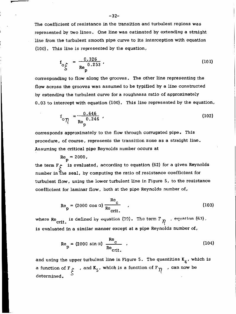
The coefficient of resistance in the transition and turbulent regions was
represented by two lines. One line w a s estimated by extending a straight
line from the turbulent smooth pipe curve to its interception with equation
(100). This line is represented by the equation,
corresponding to flow along the grooves. The other line representing the
flow across the grooves was assumed to be typified by a line constructed
by extending the turbulent curve for a roughness ratio of approximately
0 * 03 t o intercept with equation (100). This line represented by the equation,
corresponds approximately to the flow through corrugated pipe This
procedure, of course, represents the transition zone as a straight line.
Assuming the critical pipe Reynolds number occurs at
R e = 2000, P is evaluated, according t o equation (62) for a given Reynolds
the number in Fi he seal, by computing t h e ratio of resistance coefficient for
turbulent flow, using the lower turbulent line in Figure 5, to the resistance
coefficient for laminar flow , both at the pipe Reynolds number of,
R e = (2000 cos a) I
P
is cieiined by aqiiathii ($2) %e ter: F , eqt-mtinn (631 .. 7 where Re
is evaluated i n a similar manner except at a pipe Reynolds number of, crit .
Re R e = (2000 s i n a ) C #
Recrit. P (104)
and using the upper turbulent line in Figure 5. The quantities K4# which is
a function of F
determined
, and K5, which is a function of F , can now be 3 It rl

-33-
When the operation of the seal is laminar, i.e. I
F$ andFT! are equal to one, K and K are both unity and the sealing co fficient 4 5
becomes identical to equation (18). As the speed increases , F increases
causing K to decrease and thus the sealing coefficient begins i o decrease.
At even higher speeds, F also begins to increase causing K to decrease,
producing a greater decrease in the sealing coefficient. A computer pro-
gram, compiled for an I.B.M. 7040 c m p t f e r , to determine the theoretical
sealing coefficient is found in Appendix B.
III. GENERALIZING THE THEORETICAL SEALING COEFFICIENT FOR
4
77 5
LAMINAR AND TURBULENT OPERATION
In Figures 6 through 9 the theoretical sealing coefficients
(hereafter referred to as A T) equation (97) , as a function of B for
various values of Reynolds number I a 8 and
vations may be made regarding these figures:
are shown. Several obser-
1. The optimum screw geometry in the laminar range is not the
optimum geometry for turbulent operation. As shown in Figure 6 , a seal
having a n a of 5.81O has a minimum sealing coefficient for laminar
operation when r= 0.5 and B = 6.5. However , when operation becomes
turbulent the minimum value of the sealing coefficient is found at higher
values of r a n d f3. At higher a values the s a m e observation can be made.
However, the shift in the optimum B becomes smaller.
2. The f3 producing the minimum sealing coefficient i n the
turbulent range increases with increasing Reynolds number. This effect
is less significant for large a than for s m a l l a . 3 . In both laminar and turbuieni ZG-S , B given change in B
A with screws having large a than with produces a greater change in
s m a l l a. Thus from the standpoint of pressure stability the lower values
of a are to be preferred.
T
4 . In laminar operation the optimum 7 for any screw is 0 . 5. However, i n turbulent flow the sealing coefficient is improved slightly
as 7 is imreased from 0.5 to 0.7.

P
I -
36
32
28
c 24 C e W * .. .. jj 20 v ?
4- 12
1 l6
8
A 7
- 34-
-1 -n?- 1 cnnn
3VVV V. Y
1 I
I 0
1 3 5 9 11 13 15 ' 8 Figure 6 . Theoretical sealing coefficient as a function of 8 , Rec,
and )c f a r a = S ,81° , c = 0,003 in,, and D = 1,25 in,

-35-
36
32
28
24 0 0 .- .- * Tv 20 0 W 0, - *E 16 0 0 m <- 12
8
4
1 3 5 9 11 13 15 7 8 0
Pig- 7 . Thecretical sealing coefficient as a function of B, Re,, and r fora = 9.67O, c = 0,063 in., =??d I)= 1 .25 in.

-36-
36
32
28
c
24 ..I,
12
8
4
0 1 3 S 9 11 13 1s
' I 9 Fiallra 8 Theoretical sealing coefficient as a function of B, Re&,
and r f o r a = l 4 . S 0 , c = 0 . 0 0 3 i n . , a n d f i = i . 2 5 i n .

-37-
36
32
28
- 24 t 0 U .- .- u. 0
W ‘ti 20
8
4
0 3 5 11 13 15
Figure 9. Theoretical sealing coefficient as a function of B, Re,, and Z fora=20 .1S0 , c = 0 . 0 0 3 i n . , andD= 1.25in.

-38-
5. For seals which mus t operate in both the laminar and tur-
bulent regions, the smaller helfx angles will give the best values of the
sealing coefficient for both regions.
function of 7. As 7 increases the onset of turbulence occurs at lower
6. The transition from laminar to turbulent operation is a
Reynolds numbers.
of T o n A at the larger 8 values is rather pronounced. However, a s
the degree of turbulence increases this effect becomes less pronounced.
is the same a s the one
7. As the visco sea! operstion begins to be turbulent the effect
T
A T 8. At a Reynolds number of 100,
computed in equation (18), which is independent of Reynolds number.
i

-39-
CHAPTER III
TEST FACILITY AND EXPERIMENT PROCEDURE
I. TEST FACILITIES
The visco seal test section and drive is shown in Figure 10.
A detailed description of the design and construction of the experimental
facility is presented in Reference 641 . A schematic diagram of the test
section is shown in Figure 11. The sealant fluid, which was distilled
water i n all tests reported 8 was introduced under regulated pressure
through the sealant inlet. Pressure taps and thermocouples are located
along the axis of the test sleeve, the dimensional location of which are
shown in Figure 12 . Inductance probes located in two planes and 90"
apart are used to determine the eccentricity between the test sleeve and
spindle. A torque arm connected to a strain gage bridge is used to measure
the frictional torque. Since the torque measured under s o m e operational
conditions is very low, the test sleeve is mounted on eight hydrostatic
bearing pads to minimize static friction. The dimensions of the test
spindles are presented in Table III. T e s t spindles 1, 2 , 3, 4, ZB, 3 B ,
and 4 B shown in Figure 13, were threaded the total seal length. Spindles
5, 6, and 7 , shown in Figure 13, were constructed with end dams in order
to study the end effects of the seal and the phenomenon of air ingestion.
11. TEST PROCEDURE
During a test run the data recorded included spindle speed,
torque, eccentricity , pressure distribution, and temperature distribution.
Using the information in Table 111, the recorded experimental data, and the
physical piopafiies of tkc t e s t f l ~ i c ! , the experimental sealing coefficient
(hereafter referred to as AE), dissipation function, and the friction
parameter were calculated. Lambda, dissipation function, and friction
parameter were plotted versus Reynolds number based on the clearance.
The quantity aP/L in equation (97) for A E may be interpreted
in two ways. In a practical application this value should be (Psupp~y - Patmosphere )/L. However, i n this study the effect of screw geometry
on the sealing coetticient was a iacror of major c;;uiiCBiii. Theiefcjie, ir;

-40-

-4 1-
I c 0
0 a tn
-4 c,
c, m al c,

-42-
20
15
ci w
L 10 3 m m
5
0
q- 0.36'
12 l 3 14
Intercept Pressure /-
Best line through p i n t s'exc ludi ng supply pressure
\ i 1 1 1 I I
0 i 2 3 L Effective Seal Length(in.)
E -WE
Figure 12. Typical pressure and temperature gradients in the visco sza! .

I . -
I . I I I i n i u
a, u
L
a 5 iY
d m W
0
co m
m
v)
v 4
W a, Ln 4
0
v m a, 0
0
4
4 0
0
0
N v 0 0
0
0 m v hl
d
d
LD a, N
0
Tr m m
b W
a,
v a, v 0
0
W h 4 4
0
W d d 0
0
in m N 0 0
0
m W v N
d
A’
-43-
* c u o m v ) C D
0 0 I .
w e 4 0 3
w v ) . .
h b W W
a , m . .
N W v m c o d o . - I 0 0 . .
:2l c o r n 0 0
0 0 . .
h c o m h l 4 4 0 0
0 0 . .
v ) L n w w N c u 0 0 0 0
0 0 . .
d d W C D w e N c u d d . .
c r ? e
c n o N v )
0 0 . .
w m a , o c u m . .
h h w m m m . .
T r w a , - * a 3 0 0
0 0 . .
w a 3 h N d a 3 4 0
0 0 . .
v ) m N W a , - 0 4 0 0
0 0 . .
h m T r m 0 0 0 0
0 0 . .
o m N O T r v c u m . . d d
m a A2 c3
N 0) W
0
w a,
N
h co m
W v) d 4
0
* 4 In 0
0
v) 4 0 4 0
0
m m 0 0
0
co 0 Tr N
4
rn e
fi h ed
0
W a,
CD
d
a3
v)
h 0 W 0
0
v) co v) 4
0
a, h
0
0
d
v) a, N 0 0
0
m v) cy N
4
Lr?
(v 0 m 0
0 0
h
d
a3
v)
cr) co 0 4
0
0 h 0 4
0
0 a3
0
0
d
In m N 0 0
0
m m v N
d
c2
v hl h
0
0 0
fi
4 00
m
0 0 W d
0
0, 0 W 0
0
0 a3 4 0
0
in m N 0 0
0
m m v (v
d
5-

-44-
t 0
1
T 4
9 I
OD al
c a a *r OD Q) CI
3 4

-45-
order to minimize the end effects, the AP/L was interpreted as dP/dL and
evaluated as shown i n Figure 12. The viscosity of the test fluid was
evaluated at a n average temperature determined from the distribution as
shown in Figure 12 . The temperature variation in the seal was quite s m a l l
being on the order of 2 degrees F.

-46-
CHAPTER N EXPERIMENTAL RESULTS
The geometry of spindle number 1 was made similar to the one
employed by McGrew and McHugh for the purpose of comparison of exper-
imental results. A geometrical comparison of the two test spindles is shown
in Table IV.
During the iIlitial tests of spindle 1, a number of minor problems
were encountered. These problems included a ruptured oil filter, a number
of pressure tap lines which were quite long and difficult to bleed, a large
cavity at the inner end of the test seal which proved to be an air trap, and
low sensitivity in the torque measuring bridge. The details of these
difficulties and corrections are presented in reference [14] . After modi-
fication of the test apparatus, the data compared favorably in the turbulent
range, as shown in Figure 14, to the experimental curve of McGrew and
McHugh. In the laminar range, however, the value of McGrew and McHugh's
experimental curve is higher than the value of the present data, equation
(18)' or equation (15) which was derived by McGrew and McHugh.
I. SEALING COEFFICIENT
A summary of test results is presented in Table V. Using the
theory developed in Chapter 11, the theoretical sealing coefficient is
compared with the experimental values in Figures 14 through 17.
For all spindles tested I\ E remained essentially constant
during laminar operation. This result is in agreement with equation (18)
which indicates that A # f(Rec) in the laminar region. The average ratio
of 11 to L \ for i ami rmi cpeiztisr? is 0-968. During the turbulent
operation of each of the seals 2, 3, 4, 2B, 3B, and 4B, the ratio of
remained essentially constant. However, because of the varkation to T of slopes i n the turbulent region for test series 5 , 6 , and 7 , the ratio of
A n E T
E A
A was not constant. 'Eto T With the onset of turbulence fl, begins to decrease with
increasing Reynolds numbers. The Reynolds number at which transition
from laminar to turbulent operation occurb is a fiinctic?rr of 7 . In test series

-47-
0 m -9 N
4
W m In 4
0
-9 m Q) 0
0
4 0 4 0
0
N -9 0 0
0
l-l m (0
0
a3 m m
v)
-9 . 4
4
b a A & s Q)
c a M
? d
0 * m m 0
0 h hl l-l
0
0 co h 0
0
0 0
0
0
l-l
v) m 0 0
0
In hl W
0
W a0
m
In
2
rn
F
u
I:
2 2.2 e 5 3 *
c nl w G r n $ E

I - -48-
1 1 1 I I I
I - -0
m0 0 w
0 0 0
vi
U
c
- 0 Z 3 Q, L U r/) -
I I I I I
c
U Q,
QL
. 4
Q)
c a G 4
rn

I
In h
Il 0-4
m m Il Il
N m * . Il
0 * * . Il
N 0
W Il
0 cn h r(
.
cu W d 4
0
In N
N r(
W 00
cu rl
00 m 0 Il
n a 5 la d v
ir: c'
c3 00
0
4 Q)
0
W 0
4 .
* 00
0
N d
I4
N 0
Il
0 Q)
0 .
m m 0
a3 0)
0
(3 m 0
0
n
2
2: E: -4
E Y
-49-
00 m * 0
0 m v 0
v * 0
4
0
Q) 0 h
0
Q) 0 h
0
cn 0 h
0
W h W
0 .
In cn W
0
I+
cr) h
c3 .
00 m CD
0 .
n CI c: a, 1 4
9 5

- 50- I
1
,
2 , 3 , and 4, the three test spindles have essentially the s a m e a , B , c, and
D with variations in 7 only. Spindle 2 , having the lowest 7, resulted in
the longest laminar operational region, while spindle 4, with the largest 7 , resulted in the shortest operational laminar region, a5 may be observed in
Figure 15. Thus, as 7 increases the transitional Reynolds number de-
creases. The decrease in the transitional Reynolds number, defined in
equation (99)# is to be expected since the average clearance in the seal is
increasing. This direct relationship between the onset of turbulence and .. -
7 is in agreement with the theoretical projection in Chapter 11.
The relationship between ct h, was demonstrated in test
series 5, 6, and 7. The geometric parameters of spindles 5, 6 , and 7 are
essentially the same as for spindles 2 , 3 , and 4 with the exception of a which was decreased from 9.67O to 5.81O. In tests of seals having a 's
of 9.67 and 14. So, the slope of 4, d A E/dR , in the turbulent zone
was approximately - 0.70, which agrees with the theoretical prediction of C
-0.709. However, for an a of 5 .8l0 the value of d AE/dRc was found to
be approximately -0.43 for the range of experimental data recorded. The
relationship between hT and a is demonstrated in Figure 18. In this
figure it is observed that AT , for 01 equal to 5. 81°, remains laminar to
a Reynolds number of 300, while for a equal to 20. 1 S 0 , AT begins to
decrease at a Reynolds number of approximately 100. Therefore, as a increases the transition point from laminar to turbulent operation for A decreases. However, it is noted from Figure 18 that, for either large or
s m a l l a ' s , the predicted slope, d' A,/dRec, for Reynolds numbers greater
The effect of @ on A, may be observed in Figures 19, 20, and
A, for 2B, 3B,
T
--.-I AT ~G z=ot sgree. AI--- l n n n 2 - AI-- ---- T- ~ 1 - 2 - _-___ -1
' 'E ULAu L i L a i i AUUU, 13 L i i c aaiiic. ~ i i uua L G y a r u
21. In series 2B, 3B, and 4B a md 7 remain unchanged from series 2 , 3,
and 4, while B was decreased from approximately 7 to 3.
and 4B is, on the average, 1.29 times the values for spindles 2, 3, and 4
in both laminar and turbulent operation. This ratio compares favorably
with theoretical predictions which indicate that the ratio should be 1.2 8.

L
-51-
i
I
5
c3
c*3 m
.
8 w
a c kd
kd 4

- 52-
Ji 00.
I

- 53-
v 0
d d
0 c
n 0 c
a" Qt

- 54-
0 c

0 c


i
- 57-
t 0 - c
3 0 F
U 4) a
Y 0 F
0 F

I I - I I
I - 58- In test series 2B there is a sudden large increase in h at a Reynolds
number of approximately 1600. This discontinuity in h", is believed to be
the result of air ingestion which produces a decrease in the value of B. A
similar observation was made for spindles 3B and 4 B , but the perturbation
was much lower in magnitude.
A forecast of AT for tes t spindles SA, 6A, and 7A, which have
yet to be tes ted, is shown in Figure 22.
II. FRICTION PARAMETER AND DISSIPATION FUNCTION
The power loss i n the visco seal during laminar operation was
described by Stair iz terms of a dissipation function defined by the equation:
t2 7 (1 - 7 ) (B - 112(1 - 7 + TB3) P3 (1 + t2) + t2 7 (1 - a:) (P3 - 1) 2 ' + 3 @ =1-7+- 7
B
qc
xp D L U @ = 2 ,
where q is the power loss. The dissipation function depends upon 01, B , and
7 and is independent of rotational speed. The friction parameter may be
defined in terms of the dissipatidn function as:
Thus, F.P. is a function of the seal parameters and speed. The laminar experi-
mental data for the friction parameter are in agreement with equation (107) as
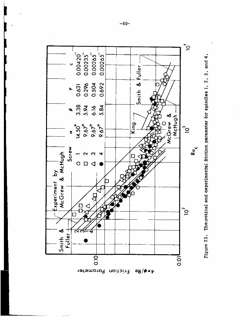
shown in Figures 23, 24, and 2 5. The experimental data in the turbulent range
follows the trend noted by Smith and Fuller p o j whose Gats fsr the kicticm
parameter of a plain journal bearing operating under laminar and turbulent
r- -1
conditions can be expressed as:
= 4 n/Rec, F-P2 and
0.43 C
F.P. = 0.156 x/Re c?

L - 59-
I
U h
- c
0 c.
b c
V 0 w
0 c
- 60-
1 1 I
LI I I I I I
0 c
0 0 c
2 w
N 0 c

-61-
I
t 0 ~
c
"0 c
U
&
(Y
0 c

- 62-
I I 1 I I I I '0 v
b c
z
0 c

-63-
As the visco seal more nearly approaches a journal bearing, 7 becoming
smaller, the experimental data for the friction parameter approaches the
l amina r experimental curve presented by Smith and Fuller. In the turbulent
region, however, the experimental data for the seal is approximately 1.0 5 1
t imes that of Smith and Fuller's. Thus, in laminar operation the friction
parameter is described by equation (107) and during turbulent operation Smith
and Fuller's turbulent journal bearing results CSTI be utilized to estimate the
friction parameter.
III. AIR INGESTION
The phenomenon designated "seal break" by McGrew and McHugh
and "secondary leak" by King was not observed directly during this experi-
mental study. The term "seal break1# refers to a sma l l l eak past the seal
interface. However, i n the present series of tests, a phenomenon which has
been termed "air ingestion" was quite evident. Air ingestion is a condition
in which air is forced, by the action of the screw exposed to air , through the
seal interface into the seal. During laminar operation air ingestion was not
obsenred. However, as the speed and degree of turbulence increased, air
bubbles began to rise in the pressure tap lines. Continuous bleeding would
not remove the entrapped air from the system once the condition of air
ingestion was present. Air ingestioii iei;c?ed tc decrease the pressure
gradient near the atmospheric end of the seal, which, in turn, increased
the effective length of the seal. The seal would not leak unless the effective
seal length required to maintain the seal supply pressure became longer than
the actual seal length or pressure fluctuations caused a slug of fluid to be
discharged.
Air ingestion was found to be related to the surface wetability
and Reynolds number of the seal. In a test series for spindle 1, in which
wetting conditions were present, t he air ingestion became severe leading t o
pulsating pressures which caused the series to be stopped. It was observed
that a i r ingestion and seal instability during this test began at a much lower
Reynolds number than in previous tests. Care was taken in all later tests
to insure that the condition of shaft wetting did not reoccur by coating aii
- 64- test spindles with a very thin film of oil.
Air ingestion may have a pronounced effect on h, in the tur- , bulent region under certain operational conditions
it is postulated that air ingestion, by displacing fluid at the root of the
In series ZB, Figure 16,
grooves, caused a decrease in B with a consequent increase in A demoastrated in Figure 26. As shown in Figure 7 , for a Reynolds number of
1000 and 8
as E'
3, a s m a l l decrease in f3 produces a large increase in the I
value of A T. This same discontinuity was observed to a smaller degree
in the data for spindle 3B and smaller yet in spindle 4B. While the f3 for
3B and 4B were similar to that for ZB, the groove widths were greater. It
is believed that the wider grooves made the displacement of liquid from the
r
root of the groove more difficult and this prevented the change in h E from
being as great as in ZB. As long as the seal's operational point is located
along the flat portions of the curves in Figures 6 through 9 , a change in B
due to air ingestion produces only a s m a l l change in the sealing coefficient,
Also, the larger the value of 7, the lower the change in B when air ingestion
is present. In order to minimize the effects of air ingestion and improve seal
stability, it appears desirable to select the seal geometry with a low a, high
, and large B values as suggested in Figures 6 through 9.
N. LONG TERM SEAL OPEWTTI'2N
To insure the feasibility of operating the visco seal for extended
periods of t i m e , a series of long term tests of one to two hours duration were
conducted for each of the spindles, beginning with 2B. In each case equi-
librium WGS r$!~ched in 15 to 20 minutes of seal operation. N o seal leakage
was observed during these long term tests and air i nyas tkn was not observed
in laminar operation, In each of the turbulent tests air ingestion was observed
to s o m e degree. However, a Reynolds number was reached where it appeared
that long term operation of the seal was not desirable. The maximum Reynolds
number at which the seal can operate in an equilibrium condition in the
turbulent zone is related to the spindle parameters. Further experimental
studies are needed ?xfc?re definite conclusions can be made regarding the

-65-
Air bubbles grow to form a pocket at root of grooves
Figure 26 . Schematic representation of the change in B due to air ingestion.

- 66-
maximum speed.
V. OTHER EXPERIMENTAL RESULTS
The effect of the eccentricity ratio on h, was predicted by
McGrew and McHugh in equation (15) to vary as E varies from 1 to 2.5 for
eccentricity ratios of 0 to 1. For laminar operation, however,
in the absence of air ingestion was found to be essentially independent
of the eccentricity ratio, while in turbulent operation A, was noted to
decrease slightly with a n increase in eccentricity ratio as can be observed
in Figure 14. It appears, therefore, unnecessary to incorporate the eccen-
tricity ratio as a significant variable in the equation for A range. It was noted, however, that eccentric operation of the seal in the
turbulent range tended to increase air ingestion.
*E,
c
in the laminar
In Figure 27 the experimental data taken from a series of tests
conducted by King, along with A computed by equation (97) for the thread
geometry used by King, are shown. The predicted sealing coefficient is in
good agreement with the 5D and 2E series of data in the turbulent range. In
the laminar range the predicted value for the sealing coefficient is smaller
than King's extrapolated data curves. It is difficult to draw conclusions
about the laminar zone since King obtained limited data in this region. In
series 3C and ilj, thz slopes cf King's experimental sealing coefficients are
- 0 . 5 2 7 and -0.466, agreeing with the slopes of 12, in test series 5 , 6, and
7 . Data curves 5D and 2E have slopes in the turbulent region of - 0.706 and
-0.686, which are s imi l a r to the values obtained in test with spindles 1
through 4B, as discussed in Chapter IV. From the experimental evidence
reported in this work, along witn aatd iiuiii Z c s , the indication is that for
s m a l l helix angles, 3 O to 6" , the initial slope of the experimental sealing
coefficient in the turbulent zone is approximately -0.46. For helix angles
of 7O to 14O corresponding to the range of optimum Q! recommendations of
various investigators, the slope of the experimental sealing coefficient is
approximately - 0.. 70.
T
i

-67-
I I
1
+ I-
+ .a ...
c

- 68-
CHAPTER V
CONCLUSIONS AND RECOMMENDATIONS
Based on the analytical laminar analysis of the visco seal
developed by Boon and T a l , equations were derived to predict the operation
of the visco seal in the laminar and turbulent regions. The theoretical
sealing coefficient developed by this analysis was compared with the experi-
mental sealing coefficient obtained for ten experimental seals. In view of
the observations and comparisons presented in this work, the following
conclusions are indicated: I
1. The laminar analysis leading to equation (18), upon which the
present analysis is based, agrees more closely with the experimental
results in laminar flow than any of the other analytical approaches con-
sidered.
2 . The optimum screw geometry for laminar operation was not optimum
for operation in the turbulent range.
3 . For screws which must operate in both the laminar and turbulent
range, smaller helix angles will provide more flexible operation in both
regions.
4 . In turbulent operation the visco seals having s m a l l helix angles
operate with a greater degree of pressure stsbility
5. Experimental A is essentially constant in laminar operation and
in agreement with equation (18).
6 . The transition Reynolds number at which A E begins to decrease,
7 . The slope of A, in the turbulent range for i i d i x ezgles of 9.67"
and 14.5" was approximately - 0.70, while this value decreased to - 0.43
for helix angles of 5.8 1 " .
decresses with increasing 7 and is in agreement with equation (99).
8. The phenomenon of air ingestion will be encountered in turbulent
operation. This condition was observed to be a function of shaft wetability,
Reynolds number, seal geometry, and eccentricity ratio, but until more
experiiiienta! c%ta are obtained this relationship cannot be precisely defined.

- 69-
However, in order to minimize the effects of air ingestion on AE I large B
and 7 along with s m a l l a should be employed.
9 . An attempt was made in test series 5 , 6 , and 7 to alleviate the
problem of air ingestion. End dams , as shown in Figure 1 3 , were added to
minimize the condition, although the end result was not as effective as was
expected. The decrease in a i r ingestion was slight necessitating the con-
clusion that more data are needed before a concrete relationship between
end dams and air ingestion can be determined.
10. There exists a maximum Reynolds number beyond which long term
operation is no longer feasible. However , more experimental data are
needed before this value can be precisely defined.
11. The frictional losses in the visco seal may be described with
existing equations. In the laminar range the theoretical predictions by
Stair closely approximate the experimental data. During turbulent operation
the experimental data presented by Smith and Fuller, represented by equation
( l o g ) , are 0 .951 t i m e s the value of the friction parameter observed in these
tests. Therefore, the frictional losses in the seal may be calculated either
for laminar or turbulent operation by:
= 41Ly/, A /Da ,
and
0 . 4 3 F.P. = 0.164n/Re 0 C
-I 1 7 - For laminar operation A E is essentially independent of E and under
turbulent conditions the effect of sea l eccentricity is sligni:.
A number of aspects of the visco seal operation in the turbulent
range require further and more intensive study. Specific problem areas
requiring additional attention are as follows:
1. More experimental data in the turbulent range for Reynolds numbers
higher than 3000 are needed in order to determine the maximum Reynolds
number for 1 s ~ ~ term seal operation.
- 70- 2 . The construction of test spindles with helix angles of approximately
5" and B ' s in the range from 10 to 20 are needed in order to verify the obser-
vations discussed in Chapter I1 concerning the relatively s m a l l effect of B
on A, for high Reynolds numbers and s m a l l helix angles.
3 . A refinement of equation (97) for the calculation of A is needed T in order to better describe the sealing coefficient in the turbulent region for
s m a l l helix angles. It is realized that the two lines in Figure 5 may not be
the best estimate for all geometric parameters.
4 . An investigation of the effects of grooves located in the housing
rather than along the shaft would be desirable. This is based on the
assumption that a smooth shaft located in the threaded housing would lessen
the effects of air ingestion on

I I
I I I I ,
I
I
I i
LIST OF REFERENCES

- 72-
LIST OF REFERENCES
1. Rowell, H. S. , and Finlayson, D. "Screw Viscosity Pumps, 'I Engineermg Vol. 126, August 31, 1928, pp. 249-250, Sept. 28, 1928, pp. 385-7,
2 . Whipple , R . T * P . "Theory of the Spiral Grooved Thrust Eearlng With U K .A e E .A. , Atomic Energy R e sea; 3 Liquid or Gas Lubricant,
Establishment, T/R 622 March 6 , 1951.
3 . Hughes, D. P. "Shaft Seal for High Gas Presswe , 'I Internaricnal Conference on Fluid Sealing , Paper C 1 , B . H e R.A e , April 1:- 19 , 1961, Harlow Essex, England.
4 e Zotov, V. A , "Research on Helical Groove Seals , 'I Russian Engineering - Tournal Translation, Vol. 10, October 1959 pp. 3- 1
5. Frossel I W "Hochtourige Schmierolpumpe , I' Konstruction. C*olo 1 2 , NO. 5 , 1960, pp. 195-203.
6. Asanuma , T . "Studies on the Sealing Action of Viscous Fluids ,. I'
"International Conference on Fluid Sealing I I' Paper A3 , B . H . R .A ,
Harlow Essex, England.
7. McGrew, J . M. and McHugh, J . D. "Analysis and T e s t of the Screw Seal in Laminar and Turbulent Operation, I' The General Electric Advanced Technology Laboratories , Report No. 63GL66, May 3 1963 I_
8 e King A e E . "Engineering Information Report on Tests Made WiTh a Xydro- dynamic Screw Seal !Viscosea!j in Oil , Water, and ??orassism" Westinghouse Electric Corporation .. Aerospace Electricai Si\-_ sic= Report No. WAED 63 3 (Revision A) , September, 1964 I
9. Boon , E . F e and T a l , S E "Hydrodynamische Dichtung fur rotierende 5 1, No 3 I Sanuary 3 1 . 19 5 9 , Wellen I I' Chemie-.lng- --- Tecknik , Lrol
pp. 202-212.
10 Stair, W K. "Analysis of the Visco Seal--Part i , i'ne G~r;ec:z:nc Laminar Case , 'I Mechanical and Aerospace Engineering Research Report ME 65-587-2, University of Tennessee, Tanuary 18, i965.
11. Pai, S e I Viscous - Flow Theory, 11, Turbulent Flow I D. Van Nostrand Company, New kork, 1957, pp. 33-37.
1 2 . Laufer, J e "Some Recent Measurements in a Two-Dimensional Turbuient Channel "Journal of Aeronautical Science, V o l . 117 I N o 5 19 50, nn r r " 277-287.

- 73-
13. Pinkus, 0. , and Sternlicht, B . Theory of Hydrodynamic Lubrication McGraw-Hill Book Company, NewYork, 1961, pp. 368-371 e
14. Bowman, C. F. “The Design and Construction of a Visco Seal T e s t Facility, ‘I Mechanical and Aerospace Engineering Research Report ME 66- 587-6 I The University of Tennessee, June 1966
15 . Smith, M I and Fuller, D . D. “Journal- Bearing Operation at I Superlaminar Speeds, “Trans. of A,S .M .E , , V o l . 7 8 , i 9 5 6 ,
pp. 469-474.

APPENDICES
. - 75-
APPENDIX A
SAMPLE CALCULATIONS
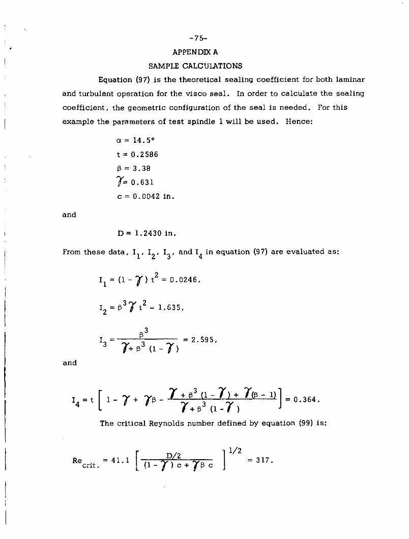
Equation (9 7) is the theoretical sealing coefficient for both laminar
and turbulent operation for the visco seal. In order to calculate the sealing
coefficient, the geometric configuration of the seal is needed. For this
examp!e the parameters of test spindle 1 will be used. Hence:
a = 14.5O
t = 0 . 2 5 8 6
B = 3 . 3 8
T= 0 . 6 3 1
c = 0 .0042 in.
and
D = 1.2430 in .
From these data, 11, 12, 13, and I in equation (97) are evaluated as: 4
= (1 - 7 ) t2 = 0 . 0 2 4 6 , I1
3 7 . 2 I2 = p 0 1 = 1.535,
R 3 P = 2 . 5 9 5 , -
T+ P3 (1 - 7 ) I3 -
and
= 0 . 3 6 4 . 1 1 - r + p - 7 + B3 (1 - 7 ) + 7(B - 1)
7+P3 ( 1 - 7 )
The critical Reynolds number defined by equation (99) is:

- 76-
are both unity. and Fr2 When the operation of the seal is laminar, F g
The t e rms K and K5, i n equation (97), can be calculated as: 3 4
1 - Ff 4 ] = 1
2 - 1 and
- r c 4 ] = 1 2 I '- 1 0 . 5 & , - 7.5 _ _ - . - 1
+ K 4 = 2Fy and
F 1 - F ] = 1 - 1.4 F n - 1
2 + - 3 - 7.5 K5- 2Fq L 1 - 10.5F;
3.92 F n \ t Therefore, the predicted sealing coefficient for laminar operation becomes:
AT = K4 ( I l + 141 2 )+ K5 (,:I = 1 (4.50) + 1 (7.23) = 11.73,
which is the s a m e value as obtained from equation (18). When the flow in
the seal becomes turbulent, F and/or F is greater than 1. Therefore, 5 77 is evaluated from Figure 5 as:
0.326 R e 0.747
Ft =(>) = = 0.00509 R e 0.253 P I
1 64 R e & S P
- or substituting for R e from equation (103),
P
r Re C = 0.00509 L 2000 cosa FE Recrit.
Similarly,
] Fr( Recrit.
Assume R e = 400. Therefore, C
0.747 .
0.754
0.747 =1.755

-77-
and
0.754 = 0.0101 [ 2000 sin 14.5 (Ej = 1.293
from which r
1.755 lO.S(l.755) - 7.5
= 0.639 I 1 - 1.755 + 3.92(1.755)2 - 1.4(1.755) - 1
and
1.293 lO.S(l.293) - 7.5 K 5 - - 2(1.293) [ l -
= 0.822 . 1 1 - 1.293 + 3.92(1.293)2 - 1.4(1.293) - 1
The theoretical sealing coefficient at Re = 400 becomes: C
A = K4 (4.50) + K5 (7.23) = 0.639 (4.50) + 0.822 (7.23) = 8.81 . T Assume Re -- 1000. Then
C
0.746 = 3.36 1000
= 0.00509 [ 2000 cos 14.5 Ft and similarly,
=2.69 ,
3.36 10.5(3.36) - 7.5 - [ 1 - K4- 2(3.36)
= 0.365 , 1 1 - 3.36 2 +
3.92(3.36) - 1.4(3.36)- 1
likewise
K,= 0.447 . 3
The theoretical sealing coefficient at Re = 1000 becomes; C

- 78- . AT = K4 (4.50) + K5 (7.23) = 0.365 (4.50) + 0.447 (7.23) = 4.885 .
These calculations are repeated for a number of assumed Reynolds numbers
in the desired range of operation from which the theoretical performance
curve may be drawn. A plot of such a curve is presented in Figure 14.
A computer program is presented in Appendix B for the calculation of
A as outlined above.

- 79-
APPENDIX B
COMPUTER PROGRAM FOR THE SEALING COEFFICIENT
The computer program for A was written in Fortran IV and run
on an I.B.M. 7040 computer. The terms in the program are related to the
nomenclature utilized in this report a s follows:
T i I
E = T P, = K4 P4 = K5
F = I4
'3 3 A = Il
B = I2 ' 'l='5 p2 = Frl

- 80-
VISCO SEAL SEALING COEFFICIENT THEORETICAL A FOR LAMINAR AND TURBULENT OPERATION
1 2 3 4 5 6 7 10 11 12 13 14 15 16
17 20 21 22 23 24 25 26 27
30 31 32 33 34
35 36 37 40 41 42 43
98 20
99 95
97
11
12
13 14
15
16
96
10
REAL LAMBDA FORMAT(//4X, lHC, 14X, 5HGAMMAl9X, SHALPHA, 13X14HBETAl 13X, lHDh PRINT 98 ==loo. DELRE=100. READ 99,C,GAMMAlALPHA,BETA,D PRINT 9 5, C , GAMMA ,ALPHA, BETA, D FORMAT(S(F10.6)) FORMAT (5 (F 1 0 .6 ,6X)) T=TAN(ALPHA/57.32) A= ( 1 5 A M MA) *T * * 2 %BETA** 3*GAMMA*T** 2 E=BETA** 3/(GAMMA+BETA** 3 * (1 . -GAMMA)) F=T* (1 .-GAMMA+GAMMA*BETA- (GAMMA+BETA**3*(1 .-GAMMA)+GAMMA* l(BETA- 1 .))/(GAMMA+BETA**3*(1 .-GAMMA))) FORMAT (12X, 2HRE I 13X, 6HLAMBDA///) REC=4 1.1*SQRT((D/2 .)/((I .-GAMMA)*C+GAMMA*C*BETA)) PRINT 97 DO 10 I=1,30 IF((RE/REC)*COS(ALPHA/57.32)-. 575) 11 , 11,12 PS1. G O T O 13 Pl=.ouSuY --n,',nnn.*fRF/REC)*COS(ALPHA/57. { L U U U ,a- 32))**.747 ~52Q./(2.*~1))*(l.-plj"(l00.5*~1-7.~)-t.'(l.-'pij/~~.~~~~?**~- 1.4*P1 1- 1 .)) IF((RE/REC)*SIN(ALPHA/57.32)-. 22 5) 14,14,15 P4= 1 G O T O 16 P2=. 0101*(2000 .*(RE/REC)*SIN(ALPHA/57.32))**. 754 P4={3.//:2 .*P2))*~1.-P2/(10.5*P2-7. 5)+(1.-P2)/(3.92*P2**2-1.4*P2 1- 1 .)) LAMBDA=P 5* (A+B)/F+P4*E/F PRINT 9 6 , RE I LAMBDA FORMAT(lOX, F6.0, lox, F8.4) IF(RE .GE .lo00 .) DELRE=400.
GO TO 20 END
RE=RE+DELRE
SENTRY