department of planning and environment · 14 november 2017 glen innes severn council po box 61 glen...
TRANSCRIPT

14 November 2017
Glen Innes Severn Council
PO Box 61
Glen Innes NSW 2370
Attention: Mr Graham Price
Re: Request for Additional Information – Department of Planning and Environment
Dear Sir
Pursuant to your correspondence dated 30th October 2017 and with reference to the request for additional information from the Department of Planning and Environment (DPE) dated 27th October 2017, Aus Tin Mining Limited (the Company), provides the following response on behalf of Taronga Mines Pty Ltd (the Proponent). Reference is also made to the Secretary Environmental Assessment Requirements (SEARs) dated 25th November 2015.
Please note all responses contained herewith relate to the Stage 1 Project, and for the avoidance of doubt are not contingent on a decision to proceed with future developments of the larger mineral resource.
Part A: Response with reference to the Secretary Environmental Assessment Requirements
DPE have requested additional information to demonstrate that sustainable rehabilitation outcomes can be achieved and that the additional information required should address directly the SEARs as previously provided. The SEARs require that the Proponent provide a conceptual strategy to address the decommissioning and rehabilitation activities to meet the nominated closure objectives and completion criteria for each domain, and that the following aspects of rehabilitation planning should be addressed:
1. Post-mining land use
2. Rehabilitation objectives and domains
3. Rehabilitation methodology
4. Conceptual final landform design
5. Monitoring and research
6. Post-closure maintenance
The Company has considered the decommissioning and rehabilitation activities to meet the nominated closure objectives for the Stage 1 Project as provided below:
1. Post-mining Land Use: The objective for post-mining land use at the site will be to achieve an overall use comparable or better than current use and to the extent possible support limited agricultural activities. Benefits of post-mining land use will include the retention of surface water harvesting infrastructure (water management areas) and useable rehabilitated grassland. It should be noted that the Stage 1 Project area is considered poor quality land (section 4.3 of the EIS) and currently does not support any agricultural activities.
2. Rehabilitation Objectives and Domains: For the Stage 1 Project, six primary domains and four secondary domains have been identified (Figure 1) in accordance with descriptions provided in ESG3: Mining Operations Plan (MOP) Guidelines, September 2013. Rehabilitation objectives for each domain are summarised in Table 1 and expanded in Appendix A.

2
Table 1 – Rehabilitation Domains and Objectives
Primary Domain Rehabilitation Objective Secondary Domain
Infrastructure Area
(Domain 1) Removal of all plant, equipment and supporting infrastructure
Domain safe and free from hazardous materials.
All roads and hardstand areas to be retained for a lawful final land use
Infrastructure Areas
Future land capability similar to or better existing land capability.
Populated by species identified in ecological assessment
Rehabilitated Land - Woodland
Tailing Storage Facility
(Domain 2)
Removal of all plant, equipment and supporting infrastructure
Domain safe and free from hazardous materials.
All roads and hardstand areas to be retained for a lawful final land use
Stable and permanent landform established.
Soils, hydrology, and grassland ecosystem with maintenance needs no greater than those of surrounding, non-mine disturbed land.
Final landform non-polluting.
Rehabilitated Land - Grassland
Water Management Area
(Domain 3)
Domain safe and free from hazardous materials.
Domain made geotechnically stable.
Soils, hydrology, and grassland ecosystem with maintenance needs no greater than those of surrounding, non-mine disturbed land.
Water Management
Area
Overburden Emplacement
(Domain 4)
Removal of all plant, equipment and supporting infrastructure
Relocation of PAF material from the surface Waste Rock Emplacement (WRE) to the void PAF WRE
Domain safe and free from hazardous materials.
All roads and hardstand areas to be retained for a lawful final land use
Stable and permanent landform established.
Soils, hydrology, and grassland ecosystem with maintenance needs no greater than those of surrounding, non-mine disturbed land.
Final landform non-polluting
Rehabilitated Land - Grassland
Void
(Domain 6) Domain made geotechnically stable and void safe
PAF material encapsulated and rehabilitated
Revegetated surrounds
Final Void
Biodiversity Offset Areas
(Domain 9)
Maximise preservation of remnant Woodland
Preserve maximum amount of remnant vegetation.
Biodiversity Offset Areas
Further to recent discussions with EPA, it is proposed the final landform for the open cut pit (void) will change from a water filled void to an open void, and Potentially Acid Forming (PAF) material will be encapsulated within the void. Design details for the long term storage of PAF will be included in the MOP but conceptual criteria are included on page 6 of this letter. Rehabilitation objectives will include adequate measures to make the void safe, including battering of pit walls, installation of fencing and signage.
For each domain, Appendix A provides for each step of achieving the rehabilitation objectives and is summarised as follows:
Step 1: Decommissioning: Decommissioning includes the cessation of infrastructure usage, its demolition and removal from the Mine Site or preparation for a supplementary post-mining land use. The order in which the decommissioning of the infrastructure occurs would

3
be determined and agreed upon prior to mine closure. Decommissioning will include the removal of all mining, processing and office/amenities facilities.
Step 2: Landform Establishment: The landform establishment phase involves the earthworks required to construct and/or profile all or part of each domain as nominated in the Stage 1 Project Approval or subsequent MOP’s. The constructed landform should be suitable for the proposed final land use and blend, as far as practicable with the adjacent topography. This stage would also include the construction of any drainage structures needed for the area.
Step 3: Growth Media Development: The growth medium development phase involves the placement of weathered overburden, subsoil and topsoil on the final landform and preparation of the surface for revegetation. Soil preparation may include fertiliser or ameliorant application and ripping or scarifying the surface.
Step 4: Ecosystem and Land Use Establishment: The ecosystem and land use establishment phase involves the establishment and maintenance of vegetation on the completed landform. On completion of ecosystem and land use establishment for a final land use of nature conservation/native vegetation on the constructed landform, an initial cover of native ground cover (grasses) will be established. Revegetation will then comprise seeding with a native tree / shrub / grass mixture as relevant for the final vegetation mix or selective planting if seeding trials fail. The criteria for completion of ecosystem and land use establishment in areas identified for agricultural use will depend on the type of agriculture to be undertaken and may include establishment of suitable pasture or planting of an initial crop.
Step 5: Ecosystem and Land Use Sustainability: The ecosystem and land use sustainability phase occurs once monitoring illustrates the achievement of relevant performance indicators with respect to ecosystem development. Areas of the landform may remain within this phase for extended periods whilst progress is made towards achieving relinquishment criteria.
Step 6: Land Relinquishment: On achievement of the nominated closure criteria for the approved mining lease, the land will be relinquished and the rehabilitation security held by the DRE released in full for that component of the final landform.
3. Rehabilitation Methodology: Rehabilitation methodologies have been developed aimed to achieve specific rehabilitation objectives of each domain with further details provide in Appendix A.
4. Conceptual Final Landform Design: Final landform will largely comprise rehabilitated woodland and grassland with key infrastructure (roads) and water management areas retained (Figure 2).
5. Monitoring and Research: Rehabilitation monitoring will monitor the progress of achieving the rehabilitation objectives for each domain. Appendix A provides specific details for rehabilitation monitoring methodology and proposed frequency. Rehabilitation monitoring will be an extension of operational monitoring and will be utilised to further refine rehabilitation methodologies.
6. Post-closure maintenance: Post-closure maintenance will be dependent on rehabilitation requirements as summarised in Table 2.

4
Table 2 – Post closure maintenance activities
Primary Domain Secondary Domain Post-closure maintenance
Infrastructure Area
(Domain 1) Infrastructure Weed control, erosion control
Rehabilitated Woodland Vegetation survey
Tailing Storage Facility
(Domain 2)
Rehabilitated Grassland Vegetation survey
Water Management Area
(Domain 3)
Water Management Area
Weed control, erosion control
Overburden Emplacement (NAF)
(Domain 4)
Rehabilitated Grassland Vegetation survey
Void and PAF Containment
(Domain 6)
Final Void Geotechnical assessment
Biodiversity Offset Areas
(Domain 9)
Biodiversity Offset Area Management actions per s.12.9 of Biobanking Assessment Methodology (OEH 2014)
Part B: Response with reference to items (a) to (d) of DPE letter dated 27th October 2017
a. Post mining land use objectives must be identified. These may be amended should a future
mining application be submitted, however until such a time a future mining operation is
approved, it must be assumed the current application is the extent of proposed mining and
land fully rehabilitated for long term land use at the cessation of the proposed mining
activity
The objective for post-mining land use at the site will be to achieve an overall use comparable or better than current use and to the extent possible support limited agricultural activities. The steps to achieving rehabilitation objectives are included in Appendix A and summarised below:
Decommissioning.
Landform Establishment.
Growth Medium Development.
Ecosystem and Land use Establishment.
Ecosystem and Land use Sustainability.
Land Relinquishment.
b. Identification of risks to achieve the final land use objectives for each domain, in particular domains that incorporate Potentially Acid Forming (PAF) material. PAF material has the potential to present long term environmental harm if not managed appropriately
Final Land Use domains for the Stage 1 Project have been characterised in accordance with ESG3 and are presented in conjunction with the rehabilitation objectives in Table 1 above. A risk assessment of the rehabilitation objectives has been undertaken in accordance with AS/NZS ISO31000:2009 Risk Management - Principles and Guidelines (also refer Section 3.3.1 of EIS for risk rating tools) and results presented in Table 3.

5
Table 3 – Risk assessment on achieving final land use
Rehabilitation Threat Potential Adverse Outcome Consequence of Occurrence
Likelihood of Occurrence
Risk Rating
Failure to remove infrastructure
Unable to complete rehabilitation or establish the identified final land use
2
D L
Failure to remove hazardous materials
Unable to complete rehabilitation or establish the identified final land use
2 D L
Failure to address contamination
Contaminated land present 2 D L
Waste Rock Emplacements is a source of contaminated leachate
3 D M
TSF is a source of contaminated leachate 4 D M
Coarse Rejects Dam is a source of contaminated leachate
3 D M
Final landform does not conform to approved final landform
Slopes too steep to be effectively rehabilitated (slope angle to be determined)
2 C M
Final landform not safe, stable and secure
Geotechnical instability of final open cut voids 3 C H
Geotechnical instability of Waste Rock Emplacements
2 C M
Geotechnical instability of TSF 3 E M
Geotechnical instability of Coarse Rejects Dam 3 D M
Public access to open cut voids possible 2 D L
Respread soil does not conform to relinquishment criteria
Insufficient soil available for rehabilitation 2 B M
Inadequate soil thickness applied to shaped landform
2 B M
Soil not capable of sustaining identified final land use/vegetation community/land capability criteria
2 D L
Final landform not non- polluting
Final landform is an unacceptable source of sediment or AMD
4 D M
Inappropriate species established during revegetation operations
Species mix on final landform does not conform with approved vegetation community
2 D L
Vegetation community does not become established
Vegetation community does not become established on final landform
2 D L
Weed or pest management fails
Weeds and pests become established and require significant resources to manage
2 C M
Vegetation community is not self -sustaining
Vegetation community is not self -sustaining 2 D L
The only risk assessed as high is the geotechnical stability of the open cut pint (Void, Domain 6).
The wall slope is currently proposed to be 70⁰ but will be assessed during operations and parameters for final closure determined thereafter.

6
The Proponent has specifically considered the risk that PAF material could generate and Section 4.2 of the EIS deals with the management and controls to reduce the potential for Acid Mine Drainage (AMD). Furthermore, the following additional controls are to be implemented to further reduce the potential for AMD:
The Rejects Dam and Tailings Storage Facility (now collectively the TSF) will be lined with a
HDPE or geomembrane liner with a maximum permeability of 1x10⁻⁹. The TSF will be
rehabilitated consistent with advice from ATC Williams (refer Appendix C).
The Process Water Pond will be lined with a HDPE or geomembrane liner with a maximum
permeability of 1x10⁻⁹. A suitable liner will be installed at each of the surface Potentially
Acid Forming (PAF) and Non Acid Forming (NAF) Waste Rock Emplacements (WRE) with all
drainage diverted to the open cut pit and then into the Process Water Pond.
PAF material temporarily stored at the surface PAF WRE (approx. 2kt) will be moved to the
void PAF WRE (total approx. 24kt). The PAF WRE within the open cut pit will employ either
a HDPE, geomembrane or clay liner with a maximum permeability of 1x10⁻⁹ such as to
provide a suitable base for containment of PAF during operations encapsulation of all PAF
material at the conclusion of operations, with water generated being diverted to the
process water pond. If required, acid neutralisation material will be blended with PAF
material.
The above measures will further reduce the potential for ground water contamination and provide for appropriate encapsulation.
A Trigger Action Response Plan has been drafted for each of the above risks and is provided in Appendix B.
c. Detailed strategies that ensure long term final land uses are realised. The strategy should
address placement, potential ground water ingress and potential discharge of leachate,
depth of cover of Non-Acid Forming (NAF) material required to isolate PAF material from
ripping and root ingress, compaction, whether sufficient NAF material is available on site
to achieve the required depth of cover, and growth media development as it is recognised
in the EIS that some areas will not have salvageable topsoil during mine development. For
example, capping strategies must be provided that demonstrate that active maintenance,
such as tree clearing in perpetuity, is not required.
The Proponent has prepared a preliminary rehabilitation strategy consistent with the conceptual requirements as required of the SEARs, with each domain summarised below and as provided in Appendix A. Further details on proposed rehabilitation will be included in the Mining Operations Plan (MOP) and the Rehabilitation Management Plan (RMP) both of which would normally be issued subsequent to a positive decision on a Development Application.
Domain 1 – Infrastructure (Infrastructure & Rehabilitated Woodland)
Domain 1 – Infrastructure Area would be retained at the end of operations in order to be utilised in Future stages at the site. However, the area will be returned to a state suitable for a lawful final land use. All non-essential infrastructure for future staged will be rehabilitated.
Decommissioning: All infrastructure not essential to rehabilitation would be removed from site; roads would remain for a final lawful land use; road access will be blocked to prevent inadvertent or deliberate vehicular access to the site following rehabilitation and may include placement of a bunds.
Landform development: Processing area will be stabilised and maintenance will be performed as required; a permanent landform will be formed and blended with the existing landscape; surface

7
water controls, including diversion structures, contour banks, sediment basins and drop structures will be installed on the final landform in accordance with the requirements of the Water Management Plan and Managing Urban Stormwater: Soils and Construction Vol 2E.
Growth Medium Development: Where applicable, a layer of NAF to a minimum thickness of [500mm] will be applied and topsoil will be placed on the shaped landform to a minimum thickness of [100mm] (a greater thickness of soil material will be spread if sufficient material is available); stockpiled topsoil will be reclaimed from the soil stockpiles and spread using a front-end loader or small bulldozer, with care taken to ensure that the placed soil is not overly compacted; the upper surface of the subsoil will be scarified to ensure that hard pans between the soil units do not develop and to facilitate infiltration of water, topsoil will be tested.
Ecosystem and Land Use Establishment: Where available, habitat elements such as logs, large rocks or broken vegetation would be placed on the final landform; open Woodland species would be used in Domain 1 (Open Woodland) and reflects composition of the existing species list identified in Table 3.1 of Geolink (2015), seed of the relevant community will be hand broadcast or spread by mechanical spreader during suitable weather, likely during late winter or early spring; the rehabilitation area will be fenced, if required, to control grazing by domestic stock and native fauna until the revegetated areas have become sufficiently established; establishment of the vegetation communities will be monitored through regular inspections.
Domain 2 – Tailing Storage Facility (Rehabilitated Grassland)
Decommissioning: All non-essential infrastructure (such as pipelines) would be removed following processing operations.
Landform Establishment: The TSF would be maintained in a stable and permanent state, to achieve
this, a stabilisation program will be implemented to ensure that all water management structures
are non-erosive, including design and construction of the final landform in accordance with the dam
design statement for trial mining operations. ATC Williams (refer Appendix C) recommend the
closure of Cell 2 (containing PAF material) comprises the following steps; Incorporation of a
dewatering system (during development/ operation phase) to aid in the drying and consolidation of
the fine materials; construction of a low permeability cover system to minimise moisture and
oxygen ingress (it is likely that the cover system would comprise a bridging/stabilisation layer, low
permeability product and cover material); and landform development to maximise the site runoff
and provide stable and non-eroding slopes and drainage features. ATC Williams recommend the
closure of Cell 1 (containing NAF) would be to develop the storage into a saturated soils cover
system (wetland area), providing retention and filtering of runoff water, or subject to design/water
balance of the wetland, the storage could be shaped to form a stable landform and shed surface
runoff, with the surface to be capped by an earthen cover system suitable to establish vegetation
and stabilisation of drainage areas
Growth Medium Development: A layer of NAF to a minimum thickness of [1000mm] will be applied and topsoil will be placed on the shaped landform to a minimum thickness of 100mm. A greater thickness of soil material will be spread if sufficient material is available; stockpiled topsoil will be reclaimed from the soil stockpiles and spread using a front-end loader or small bulldozer, with care taken to ensure that the placed soil is not overly compacted; the upper surface of the subsoil will be scarified to ensure that hard pans between the soil units do not develop and to facilitate infiltration of water; and topsoil will be tested.
Ecosystem and Land Use Establishment: Where available, habitat elements such as logs, large rocks or broken vegetation would be placed on the final landform; seed of the relevant community will be hand broadcast or spread by mechanical spreader during suitable weather, likely during late winter or early spring; the rehabilitation area will be fenced, if required, to control grazing by domestic stock and native fauna until the revegetated areas have become

8
sufficiently established, establishment of the vegetation communities will be monitored through regular inspections.
Domain 3 – Water management area (Water management area)
Decommissioning: All non-essential infrastructure (such as pipelines) would be removed following stage 1 processing operations; and undertake a final stability investigation of dam wall structure
Landform Establishment: The proponent will aim to establish a permanent water diversion around the TSF and to establish a long-term vegetative cover as part of the water management area. This will aid in returning a sustainable and natural drainage system to the area. Vegetation will also aid to minimise erosion of long-term water management structures; removal of unnecessary surface water management structures in order to return the natural water shed of the project area; works would be carried out in order to form a Farm Dam B for future lawful post mining land use based on operational monitoring.
Growth Medium Development: Topsoil will be placed within the shaped landform.
Ecosystem and Land Use Establishment: Where available, vegetative cover will be recovered from across the Stage 1 Project area and transplanted into diversion drains; the rehabilitation area will be fenced, if required, to control grazing by domestic stock and native fauna until the revegetated areas have become sufficiently established; and the establishment of the vegetation communities will be monitored through regular inspections.
Domain 4 – Overburden Emplacement Area (NAF) (Rehabilitated Grassland)
Landform establishment: Completed sections of the NAF WRE would be clearly identified on the ground to prevent further inadvertent placement of waste rock. The outer faces of the emplacement would be reshaped to achieve the following; a maximum final slope of 1:3 (V:H); berms approximately 5m wide and spaced every 10m vertically on the final landform with a back slope of approximately 1:20 (V:H) and a longitudinal slope of approximately 1:200 (V:H). The upper surface of the emplacement will be shaped to form a rolling landform.
Growth Medium Development: Surface water controls, including diversion structures, contour banks, sediment basins and drop structures will be installed on the final landform in accordance with the requirements of Landcom (2004) and DECC (2008). Topsoil will be placed on the shaped landform to a minimum thickness of [100mm]. A greater thickness of soil material will be spread if sufficient material is available; stockpiled topsoil will be reclaimed from the soil stockpiles and spread using a front-end loader or small bulldozer, with care taken to ensure that the placed soil is not overly compacted. The upper surface of the subsoil will be scarified to ensure that hard pans between the soil units do not develop and to facilitate infiltration of water. Subsoil and topsoil separate out will be placed on the shaped landform to a minimum thickness of 100mm. A greater thickness of soil material will be spread if sufficient material is available. The upper surface of the topsoil will be left even but roughened to facilitate infiltration of water and retention of spread seed and topsoil will be tested.
Ecosystem and Land Use Establishment: Where available, habitat elements such as logs, large rocks or broken vegetation would be placed on the final landform and the waste rock emplacements will be rehabilitated to a mixture of grassland and mixed grassland/woodland broadly consistent with the composition of the existing ecological community (the distribution of each of these communities will be determined based on the results of the rehabilitation trials). However, in order to minimise detrimental effects to stability of the final landform, the upper and low-slope surfaces of the emplacements will be used to establish grassland/woodland community, while the sides and higher-slope sections will be used to establish a grassland community. This will facilitate management of erosion and sediment control because the trees

9
will not suppress groundcover vegetation, thereby ensuring greater ground coverage and limited potential for erosion. Species to be indicatively used for each of the identified vegetation communities are presented in Table 3.1 of Geolink 2015 and species to be used during rehabilitation will be reviewed as a result of the outcomes of the rehabilitation trials and will present and justify adjustments to the species list as part of the Annual Environmental Management Report process. Seed of the relevant community will be hand broadcast or spread by mechanical spreader during suitable weather, likely during late winter or early spring. The rehabilitation area will be fenced, if required, to control grazing by domestic stock and native fauna until the revegetated areas have become sufficiently established. Establishment of the vegetation communities will be monitored through regular inspections.
Domain 6 – Void (Final Void)
As part of rehabilitation, the objective for the Open Cut Pit is to provide a geotechnical stable and safe final land form. The Open Cut Pit would be utilised in order to manage PAF material derived from mining operations.
Decommissioning: Non-essential equipment for landform establishment would be removed from site.
Landform Establishment: Pit bench angles will be reduced to an angle to be finalised following mining operations; top of pit face to be scalloped to blend with surrounding topography and facilitating conditions more favourable for natural revegetation. A geotechnical assessment of the final void would be conducted to ensure the final landform is stable. PAF material temporarily stored at the surface PAF WRE (approx. 2kt) will be moved to the void PAF WRE (total approx. 24kt). The PAF WRE within the open cut pit will employ either a HDPE, geomembrane or clay liner with a maximum permeability of 1x10⁻⁹ such as to provide a suitable base for containment of PAF during operations encapsulation of all PAF material at the conclusion of operations, with water generated being diverted to the process water pond. If required, acid neutralisation material will be blended with PAF material. A layer of NAF to a minimum thickness of [1000mm] will be applied and topsoil will be placed on the shaped landform to a minimum thickness of [100mm]. A greater thickness of soil material will be spread if sufficient material is available; stockpiled topsoil will be reclaimed from the soil stockpiles and spread using a front-end loader or small bulldozer, with care taken to ensure that the placed soil is not overly compacted. The upper surface of the subsoil will be scarified to ensure that hard pans between the soil units do not develop and to facilitate infiltration of water. Subsoil and topsoil separate out will be placed on the shaped landform to a minimum thickness of 100mm. A greater thickness of soil material will be spread if sufficient material is available. The upper surface of the topsoil will be left even but roughened to facilitate infiltration of water and retention of spread seed and topsoil will be tested..
Ecosystem and Land Use Establishment: Where available, habitat elements such as logs, large rocks or broken vegetation would be placed on the final landform. Seed of the relevant community will be hand broadcast or spread by mechanical spreader during suitable weather, likely during late winter or early spring. The rehabilitation area will be fenced, if required, to prevent inadvertent disturbance by Mine-related activities and to control grazing by domestic stock and native fauna until the revegetated areas have become sufficiently established. Establishment of the vegetation communities will be monitored through regular inspections.
Domain 9 – Conservation and Biodiversity Offset Areas
The Proponent will establish Biodiversity Offset Areas within Lot 2, DP 1008294 (Figure 1) consistent with the Biobanking Assessment Methodology (OEH 2014). The Proponent has completed a Biodiversity Offset Report and agreed a pathway with Office of Environmental Heritage. The Biodiversity Offset Area is proposed to be documented by way of a Voluntary Planning Agreement (VPA) with the Glen Innes Severn Council. Details of the area to be incorporated, and the future

10
management of the area consistent with s12.9 of the Biobanking Assessment Methodology (OEH 2014) with be formalised in the VPA.
The DPE in its letter of 27th October 2017 requests specific details relating to the amount and application of Non-Acid Forming (NAF) material for rehabilitation. The Proponent considers the provision of such information would reasonably be expected in the MOP, and Table 2.6 from the EIS indicates approximately 50,000 tonnes of NAF will be generated and available for rehabilitation purposes, but this would be provided and undated as necessary in the MOP.
d. Care and Maintenance activities for a specified period must be detailed to ensure all PAF
material is appropriately managed and water management infrastructure is maintained.
Care and maintenance will be an extension of operational monitoring and maintenance activities. The duration of care and maintenance activities will be that sufficient required to finalise future mining operations following trial mining operations should it prove future mining operations are viable or until a decision to progress final rehabilitation is made.
Care and maintenance activities would include the continued implementation of the following;
Implementation of procedures stipulated as “Phase 1 rehabilitation” outlined in Section
2.13 of the EIS.
Operational and safety manuals for proposed dams;
Dewatering of Open Cut Pit to dam facilities;
Weed and Hygiene management;
Continued operational surface water, groundwater and all other monitoring activities
Continued implementation of standard environment operational procedures.
Please do not hesitate to contact the undersigned on (07) 3303 0611 or [email protected] if you have any queries.
Sincerely,
Peter Williams Chief Executive Officer

11
Figure 1 – Primary and Final Domains

12
Figure 2 – Conceptual Final landform Design

13
Appendix A – Stage 1 Project Rehabilitation Program
Stage 1 - Decommissioning
Objective Performance Indicator Performance Measure Relinquishment criteria Rehabilitation Monitoring
Methodology Monitoring Frequency
Timing relationship
Domain 1 – Infrastructure Area
All infrastructure and services not suitable for a lawful final land use will be removed
Infrastructure removed Infrastructure not required for final land use removed
Relevant infrastructure removed Photographs Following decommissioning
Following
Operations
All roads and work platforms areas to be retained for a lawful final land use reduced in width to that suitable for final land use.
Roads removed Roads not required for final land use are removed
Roads removed unless permitted for agricultural or other approved activity or that agreed with landowners
Photographs Following decommissioning
Following
achievement of
infrastructure
removal
performance
measure
Remaining roads reduced in width
Road reduced in width to that suitable for final lawful land use
Required width identified and roads reduced to comply with relevant legislation
Photographs Following decommissioning
Work platform areas reduced or removed
Work platform areas reduced in size to that suitable for final lawful land use or removed fully
Permitted hardstand areas identified and remainder removed
Photographs Following decommissioning
Domain safe and free from hazardous materials
Contaminated land identified and remediated
Contaminated land assessment indicates contamination acceptable for final land use
No contamination remaining at surface Contamination report prepare by qualified person
Following decommissioning
Following removal
of reduced roads
No hazardous materials remain All hazardous materials removed No hazardous materials remain on site Contamination report prepare by qualified person
Following decommissioning
Domain 2 - Tailing Storage Facility
Infrastructure removed and domain stable and non-polluting and grassland established.
Pipework and associated infrastructure inspected
All necessary pipework and associated infrastructure fitted or retained
necessary pipework and associated infrastructure fitted or retained
Photographs Following decommissioning
Following
operations
Facility structurally sound Technical assessment and indication that facility is structurally sound
notification of successful decommissioning received
Independent engineers report to appropriate authority
Ongoing and following decommissioning
Following
pipework
fitting/removal
Landform non-polluting Surface water and groundwater monitoring
Monitoring indicates that leachate complies with trigger values determined in accordance with ANZECC (2000)
Water quality testing as per the approved Water Management Plan
Monthly during and immediately following operations, and
Monthly during
and immediately
following

14
Objective Performance Indicator Performance Measure Relinquishment criteria Rehabilitation Monitoring Methodology
Monitoring Frequency
Timing relationship
then less frequently following completion of the Mine
operations, and
then less
frequently
following
completion of
the Mine
Domain 3 – Water Management Area
Domain stable and non-polluting Redundant water management structures removed
Water management structures not required for the final land use removed
Redundant water management structures identified and removed
Plan showing redundant structures Photographs
Following decommissioning
Following
operations
Remaining water management structures non-polluting
Surface water and groundwater monitoring
Monitoring indicates that surface water complies with trigger values determined in accordance with ANZECC (2000)
Water quality monitoring as per the Water Management Plan
Monthly during and immediately following operations, and then less frequently following completion of the Mine
Monthly during
and immediately
following
operations, and
then less
frequently
following
completion of
the Mine

15
Stage 2 – Landform Establishment
Domain 1 – Infrastructure Area
Land capability similar to existing land capability
Landform similar to pre-Stage 1 Project landform
Comparison between pre-mining and post-mining plans
Mapping confirms that, with the exception of dams and final void to be retained, landform is free draining and consistent with the pre-mining landform
Photographs Following decommissioning
Following
decommissioning
Suitable surface water controls installed and operating effectively
Surface water quality Monitoring of water discharged from the project area complies with limits No identifiable erosion or sedimentation
Water quality testing as per the approved Water Management Plan
Photographs
Monthly during and immediately following operations, and then less frequently following completion of the Mine
Following technical
assessment and
indication that facility
is structurally sound
Domain 2 - Tailings Storage Facility
Stable and permanent landform established
Residue fully settled Rate of residue settlement Monitoring indicates that residue settling/dewatering is complete/reduced to an acceptable level
Surveys of residue surface
Following decommissioning
Technical assessment
and indication that
facility is structurally
sound
Landform suitable for growth media establishment
Final slope to be determined All slopes stabilised and reduced to 20o As constructed survey plans
Following completion of demobilisation
Following technical
assessment
Suitable drainage structures installed
Drainage structures capable of transferring water from the facility without eroding
Drop structures constructed as per Landcom (2004) no erosion or sedimentation evident
As constructed survey plans
Photographs
Following completion and 6 monthly
Following
decommissioning
Landform non-polluting Leachate (if present) of acceptable quality
Leachate quality Surface water quality
Monitoring indicates that leachate (if present) complies with trigger values for upland river systems determined in accordance with ANZECC (2000) guidelines
Water quality testing as per the approved Water Management Plan
Monthly during and immediately following operations, and then less frequently following completion of the Mine
Ongoing

16
Suitable surface water controls installed and operating effectively
Surface water quality
Monitoring of water discharged from the project area complies with limits to be determined with relevant agencies and no notable erosion or sedimentation
Water quality testing as per the approved Water Management Plan
Photographs
Monthly during and immediately following operations, and then less frequently following completion
Following
decommissioning
Domain 3 – Water Management Area
Stable and permanent landform established
Final slope Final slopes to be reduced to 20o As constructed survey plans
Following completion of demobilisation
Technical assessment
Following technical
assessment
Landform non-polluting Suitable surface water controls installed and operating effectively
Surface water quality Monitoring of water discharged from the project area complies with limits No identifiable erosion or sedimentation
Water quality testing as per the approved Water Management Plan
Photographs
Monthly during and immediately following operations, and then less frequently following completion of the Mine
Monthly during and
immediately following
operations, and then
less frequently
following completion of
the Mine
Domain 4 – Waste Rock Emplacement Area
Stable and permanent landform established
Landform geotechnically stable Geotechnical stability of the landform
Geotechnical report indicating no evidence of instability of emplacements
Independent engineers report
Ongoing and following decommissioning
Following
decommissioning of
Void
Domain 5 – Overburden Emplacement Area
Domain Stable and Non Polluting
Topsoil applied in accordance with rehabilitation management plan
Topsoil relocated and tracked (i.e weight measured) and applied in accordance with rehabilitation management plan
Topsoil relocated and applied in accordance with rehabilitation management plan
Photographs Following decommissioning
Following growth medium
development of various
domains
Subsoil applied in accordance with final rehabilitation management plan
Stability of final landform Geotechnical report indicating no evidence of instability
Photographs Following decommissioning
Following growth medium
development of various
domains
Domain 6 - Void
Domain made geotechnically stable and free from hazards
Landform geotechnically stable Geotechnical stability of the landform
Geotechnical report indicating no evidence of instability of emplacements
Independent engineers report
Ongoing and following decommissioning
Following operations

17
Stage 3 – Growth Media Development and Stage 4 Ecosystem and land Use Establishment
Domain 1 – Infrastructure Areas
Soils, hydrology and woodland ecosystem with maintenance needs no greater than those of surrounding, non-Stage 1 Mine disturbed land
Soil thickness on shaped landform
Test pits excavated, logged and photographed
Soil material at least 100mm thick unless rehabilitation trials indicate that an alternative thickness is acceptable
Photographs
Test pits
Following spreading of soil
Following
landform
establishment
Soil characteristics in the range of pre-mining soil characteristics for skeletal Red Chromosol soils
Physical and chemical soil characteristics
Criteria to be established but to be comparable with skeletal Red Chromosol evident
Soil monitoring report outlining the results of physical and laboratory soil tests
Following spreading of soil and annually thereafter
Following
growth
medium
establishment
Suitable surface water controls installed and operating effectively
Surface water quality Monitoring of water discharged from the Stage 1 Mine Site limits No identifiable erosion or sedimentation
Water quality testing as per the approved Water Management Plan Photographs
Monthly during and immediately following operations, and then less frequently following completion of the Stage 1 Mine
Monthly during
and immediately
following
operations, and
then less
frequently
following
completion of
the Mine
Domain 2 – Tailing Storage Facility
Soils, hydrology, and grassland ecosystem with maintenance needs no greater than those of surrounding, non-mine disturbed land
Upper surface of facility capped with NAF clay
Geotechnical report Capping parameters will be defined following commencement of rehabilitation trials
Geotechnical report by a qualified individual
On completion Following final
landform
establishment
Soil thickness on shaped landform
Application monitored and measures logged and photographed
Soil material at least 100mm thick unless rehabilitation trials indicate that an alternative thickness is acceptable
Test pits (if required)
Photographs
Following spreading of soil
Following final
landform
establishment
Soil characteristics in the range of pre-mining soil characteristics for Red Chromosol soils
Physical and chemical soil characteristics
Criteria to be established but to be comparable with skeletal Red Chromosol evident
Soil monitoring report outlining the results of physical and laboratory soil tests
Following spreading of soil and annually thereafter
Following
capping and
soil
application

18
Suitable surface water controls installed and operating effectively
Surface water quality Monitoring of water discharged from the Stage 1 Mine Site limits No identifiable erosion or sedimentation
Water quality testing as per the approved Water Management Plan
Photographs
Monthly during and immediately following operations, and then less frequently following completion of the Stage 1 Mine
Following
capping and
soil
application
Domain 3 – Water Management Area
Domain stable and non-polluting Water management structures stabilised and capable of retaining and conveying water without causing pollution
Design of structures Design in accordance with surface water reports and engineering reports (2017) No identifiable erosion or sedimentation
Visual inspection
Photographs
Initially weekly and after every rainfall event >5mm
Following
capping and
soil
application
Water discharged from site within relevant criteria.
Monitoring of water discharged from the Stage 1 Mine Site
Monitoring of water discharged from the Stage 1 Mine Site
Water quality testing as per the approved Water Management Plan
Monthly during and immediately following operations, and then less frequently following completion of the Stage 1 Mine
Monthly during
and immediately
following
operations, and
then less
frequently
following
completion of
the Mine
Domain 4 – Overburden Emplacement Area
Stable and permanent landform established
Soil thickness on shaped landform
Test pits excavated, logged and photographed
Soil material at least 100mm thick unless rehabilitation trials indicate that an alternative thickness is acceptable
Photographs
Test pits
Following spreading of soil
Following final
landform
establishment
Suitable surface water controls installed and operating effectively
Surface water quality Monitoring of water discharged from the Stage 1 Mine Site limits No identifiable erosion or sedimentation
Water quality testing as per the approved Water Management Plan
Photographs
Monthly during and immediately following operations, and then less frequently following completion of the Stage 1 Mine
Following final
landform
establishment
and growth
media
development

19
Soils, hydrology, and grassland ecosystem with maintenance needs no greater than those of surrounding, non-mine disturbed land
Soil characteristics in the range of pre-mining soil characteristics for Red Chromosol soils
Physical and chemical soil characteristics
Criteria to be established but to be comparable with skeletal Red Chromosol evident
Soil monitoring report outlining the results of physical and laboratory soil tests
Following spreading of soil and annually thereafter
Following
landform
establishment
Domain stable and non-polluting WRE stabilised and capable of retaining and conveying water without causing pollution Water discharged from site within relevant criteria.
Geochemical assessment Monitoring of water discharged from the Stage 1 Mine Site
Geochemical monitoring in line with Waste Rock Management plans No identifiable erosion or sedimentation Monitoring of water discharged from the Stage 1 Mine Site
Geochemical assessment Visual inspection Photographs
Water quality testing as per the approved Water Management Plan
Following spreading of soil Monthly during and immediately following operations, and then less frequently following completion of the Stage 1 Mine
Following final
landform
establishment
and growth
media
development
Domain 5 – Stockpiled material
Stable and permanent landform established
Soil thickness on shaped landform
Test pits excavated, logged and photographed
Soil material at least 100mm thick unless rehabilitation trials indicate that an alternative thickness is acceptable
Photographs
Test pits
Following spreading of soil
Following final
landform
establishment
and growth
media
development
Suitable surface water controls installed and operating effectively
Surface water quality Monitoring of water discharged from the Stage 1 Mine Site limits No identifiable erosion or sedimentation
Water quality testing as per the approved Water Management Plan
Photographs
Monthly during and immediately following operations, and then less frequently following completion of the Stage 1 Mine
Following final
landform
establishment
and growth
media
development

20
Stage 5 – Ecosystem and land Use Sustainability
Domain 1 - Infrastructure
Remaining infrastructure suitable for a lawful final land use
Remaining infrastructure suitable for a lawful final land use
Remaining infrastructure suitable for a lawful final land use
Remaining infrastructure suitable for a lawful final land use
Remaining infrastructure suitable for a lawful final land use
Remaining infrastructure suitable for a lawful final land use
Domain 5 – biodiversity offset area
Maximise preservation of open woodland Ecological Communities
Offset areas protected Conservation Property Vegetation Plan
Offset area management plan implemented. Offset areas signposted and access managed for biodiversity purposes Offset areas signposted and access managed for biodiversity purposes
Audit against plan requirements
Visual inspections
Photographs
Following implementation and then annually
Following final
landform
establishment
and growth
media
development
Preserve maximum amount of remnant vegetation.
Diversity of species consistent with the analogue community identified in Geolink (2015)
Vegetation survey Species diversity consistent with the analogue community identified in GEOlink (2015)
Assessment report prepared by suitably qualified person
As required by suitably qualified consultant
ongoing
Stage 6 – Land Relinquishment
All domains
Final relinquishment will rely on sustained demonstration of compliance with relinquishment criteria for Stage 5 – Ecosystem and land Use Sustainability
Demonstrated compliance with the above
Note 1: Monitoring frequency to be reviewed and adjusted in consultation with relevant government agencies following analysis and reporting of initial monitoring results
21
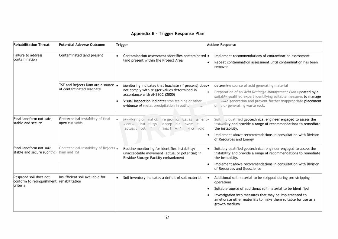
Appendix B – Trigger Response Plan
Rehabilitation Threat Potential Adverse Outcome Trigger Action/ Response
Failure to address contamination
Contaminated land present Contamination assessment identifies contaminated
land present within the Project Area
Implement recommendations of contamination assessment
Repeat contamination assessment until contamination has been
removed
TSF and Rejects Dam are a source of contaminated leachate
Monitoring indicates that leachate (if present) does
not comply with trigger values determined in
accordance with ANZECC (2000)
Visual inspection indicates iron staining or other
evidence of metal precipitation in outflow zones
determine source of acid generating material
Preparation of an Acid Drainage Management Plan updated by a
suitably qualified expert identifying suitable measures to manage
leachate generation and prevent further inappropriate placement
of acid- generating waste rock.
Final landform not safe, stable and secure
Geotechnical instability of final open cut voids
Monitoring or final closure geotechnical assessment
identifies instability/ unacceptable movement
(actual or potential) in final face of open cut void
Suitably qualified geotechnical engineer engaged to assess the
instability and provide a range of recommendations to remediate
the instability.
Implement above recommendations in consultation with Division
of Resources and Energy
Final landform not safe, stable and secure (Cont’d)
Geotechnical instability of Rejects Dam and TSF
Routine monitoring for identifies instability/
unacceptable movement (actual or potential) in
Residue Storage Facility embankment
Suitably qualified geotechnical engineer engaged to assess the
instability and provide a range of recommendations to remediate
the instability.
Implement above recommendations in consultation with Division
of Resources and Geoscience
Respread soil does not conform to relinquishment criteria
Insufficient soil available for rehabilitation
Soil inventory indicates a deficit of soil material Additional soil material to be stripped during pre-stripping
operations
Suitable source of additional soil material to be identified
Investigation into measures that may be implemented to
ameliorate other materials to make them suitable for use as a
growth medium

22
Rehabilitation Threat Potential Adverse Outcome Trigger Action/ Response
Respread soil does not conform to relinquishment criteria (Cont’d)
Soil not capable of sustaining identified final land use/vegetation community/land capability
Topsoil parameters not similar to those evident
prior to mining.
Suitably qualified agronomist or soil scientist engaged to prepare
a report including a range of recommendation to ensure that the
identified closure criteria are achieved
Implement above recommendations in consultation with Division
of Resources and Geoscience
Final landform not non- polluting
Final landform is an unacceptable source of sediment
Surface water monitoring or visual inspection
indicates that final landform is eroding or is a
source of unacceptable levels sedimentation
Remediate eroding area through additional earthworks, soil
works, revegetation or other stabilisation works.
If the above is unsuccessful, engage a suitably qualified
professional in sediment and erosion control to prepare an
assessment report and recommendations
Implement above recommendations in consultation with Division
of Resources and Energy
Inappropriate species established during revegetation operations
Species mix on final landform does not conform with approved vegetation community
Monitoring indicates that species mix on the final
landform does not match the approved species mix
Suitably qualified ecologist or revegetation expert engaged to
assess reasons for divergence of species mix and recommend
actions to ensure that the final vegetation community
corresponds as closely as possible to the approved community
Implement above recommendations in consultation with Division
of Resources and Energy
Identified vegetation communities do not become established
Vegetation community does not become established on final landform
Monitoring indicates that revegetation program has
failed or partially failed
Suitably qualified ecologist or revegetation expert engaged to
assess reasons for failure of revegetation program and
recommend actions to ensure that revegetation is successful
Vegetation community is not self-sustaining
Landscape Function Analysis indices not trending towards analogue site for same vegetation community
Monitoring of the rehabilitated landform indicates
that progress towards identified indices is slower
than anticipated or non-existent
Suitably qualified ecologist or revegetation expert engaged to
assess reasons for additional management requirements and
recommend actions to align management required with that of
the analogue sites
Implement above recommendations in consultation with Division
of Resources and Geoscience

23
Appendix C – Site Closure Strategy (ex ATC Williams, 13/11/17)
Site Closure Objectives
Closure objectives as outlined in the mining operations plan (MOP):
Create a stable final landform suitable for post mining land use and agreed agricultural activities;
Safe, stable and non-polluting after closure and relinquishment;
Limited long-term environmental impact and liability after closure and relinquishment;
Meet relevant regulatory requirements for successful closure and rehabilitation of TSF Cell 1 and Cell 2; and
Limited requirement for long term surface and groundwater monitoring after closure and relinquishment.
Tailings and Coarse Rejects Closure
Based on above and initial advice from Aus Tin Mining, material types, characteristics and conceptual closure strategies are as follows:
Material Inferred
Characteristics Conceptual Closure Strategy
Tailings/Slimes (TSF Cell 1) – PAF material, fine grind produced by a slurry deposition.
Inferred that the
material would
likely have a low
strength and that
contact water with
the material would
likely have adverse
environmental
impacts.
The conceptual management strategy would be to encapsulate the material to minimise oxidation/acid and
metals mobilisation, and contain seepage/ contact water. It is noted that the proposed development comprises
a lined/low permeability foundation treatment to minimise seepage.
Closure of the storage could be addressed as follows:
Incorporation of a dewatering system (during development/ operation phase) to aid in the drying and
consolidation of the fine materials.
Construction of a low permeability cover system to minimise moisture and oxygen ingress. It is likely that
the cover system would comprise a bridging/stabilisation layer, low permeability product and cover
material.
Landform development to maximise the site runoff and provide stable and non-eroding slopes and drainage
features.
Coarse Rejects (TSF Cell 2) – Expected to be
chemically benign, coarse grind typically
comprising quartz, feldspar, muscovite and
sericite, and produced as a cyclone product
Inferred to have
moderate strength
(i.e. able to be
engineered using
As the material is currently not expected to be chemically reactive, the management strategy would be to
develop a landform that is stable in terms of stability and erosion.
In addition, as the Cell 2 is located downstream of Cell 1, it is considered that the storage could provide interim

24
from the process. Minerals such as cassiterite,
sulphides, and topaz will mostly be removed
in the process.
conventional
methods) and
largely be free
draining
containment of runoff from Cell 1 during the closure works and longer term be incorporated as a
secondary/passive water management system for runoff from both Cells.
The proposed approach would be to develop the storage into a saturated soils cover system (wetland area),
providing retention and filtering of runoff water.
Alternatively, subject to design/water balance of the wetland, the storage could be shaped to form a stable
landform and shed surface runoff, with the surface to be capped by an earthen cover system suitable to
establish vegetation and stabilisation of drainage areas.
Due to the limited scale of the proposed trial mine, alternate closure options (in terms of economics and environmental outcomes) may
also exist, including removal of PAF materials back into the mine void and/or chemical stabilisation of the PAF materials.